

Sony XRCA-340 Service manual
XR-CA330/CA340
SERVICE MANUAL
Ver 1.3 2003.08
Photo: XR-CA330
SPECIFICATIONS
AUDIO POWER SPECIFICATIONS (US model)
POWER OUTPUT AND TOTAL HARMONICDISTORTION
22 watts per channel minimum continuous average power into 4 ohms, 4 channels
driven from 20 Hz to 20 kHz with no more than 5 % total harmonic distortion.
Other specifications
Cassette
Tape track 4-track 2-channel stereo
Wow and flutter 0.13 % (WRMS)
Frequency response 30 – 15,000 Hz
Signal-to-noise ratio 55 dB
Tuner section
FM
Tuning
Aerial terminal External aerial connector
Intermediate frequency 10.7 MHz
Usable sensitivity 11 dBf
Selectivity 75 dB at 400 kHz
Signal-to-noise ratio 62 dB (stereo),
Harmonic distortion at 1 kHz
Separation 33 dB at 1 kHz
Frequency response 30 – 15,000 Hz
AM
Tuning range
player section
range
XR-CA330
FM tuning interval:
87.5 – 107.9 MHz
(at 200 kHz step)
XR-CA340
FM tuning interval:
50 kHz/200 kHz
switchable
87.5 – 108.0 MHz
(at 50 kHz step)
87.5 – 107.9 MHz
(at 200 kHz step)
68 dB (mono)
0.7 % (stereo),
0.5 % (mono)
XR-CA330
AM tuning interval:
530 – 1,710 kHz
(at 10 kHz step)
XR-CA340
AM tuning interval:
9 kHz/10 kHz switchable
531 – 1,602 kHz
(at 9 kHz step)
530 – 1,710 kHz
(at 10 kHz step)
US Model
XR-CA330
E Model
XR-CA340
Model Name Using Similar Mechanism NEW
Tape T r ansport Mechanism Type MG-36SZ12-32
Aerial terminal External aerial connector
Intermediate frequency 10.7 MHz/450kHz
Sensitivity 30 µV
Power amplifier section
Outputs Speaker outputs
Speaker impedance 4 – 8 ohms
Maximum power output 45 W × 4 (at 4 ohms)
General
Outputs Audio output
Input (XR-CA340 only) Telephone ATT control
Tone controls
Power requirements 12 V DC car battery
Dimensions Approx. 178 × 50 × 178 mm
Mounting dimensions Approx. 182 × 53 × 161 mm
Mass Approx. 1.2 kg (2 lb 10 oz.)
Supplied accessories Parts for installation and
Design and specifications are subject to change
without notice.
(sure seal connectors)
Power aerial relay control
lead
Power amplifier control
lead
lead
XR-CA330
Bass ±10 dB at 20 Hz
Treble ±10 dB at 20 kHz
XR-CA340
Bass ±9 dB at 100 Hz
Treble ±9 dB at 10 kHz
(negative earth)
1
/8 × 2 × 7 1/8 in.)
(7
(w/h/d)
1
/4 × 2 1/8 × 6 3/8 in.)
(7
(w/h/d)
connections (1 set)
Front panel case (1)
FM/AM CASSETTE CAR STEREO
9-873-346-04 Sony Corporation
2003H05-1 e Vehicle Company
C 2003.08 Published by Sony Engineering Corporation

XR-CA330/CA340
Ver 1.2
TABLE OF CONTENTS
1. GENERAL
Location of Controls ....................................................... 3
Setting the Clock ............................................................. 3
Installation....................................................................... 4
Connections ..................................................................... 5
2. DISASSEMBLY
2-1. Disassembly Flow ........................................................... 8
2-2. Sub Panel ......................................................................... 8
2-3. Mechanism Deck (MG-36SZ12-32) ............................... 9
2-4. MAIN Board ................................................................... 9
2-5. Heat Sink ......................................................................... 10
2-6. Bracket (MD) .................................................................. 10
2-7. Motor (Capstan/Reel) (M901) ........................................ 11
2-8. Main Belt, Sub Belt (C) .................................................. 11
2-9. Head (Playback) (HP901) ............................................... 12
3. MECHANICAL ADJUSTMENTS....................... 13
4. ELECTRICAL ADJUSTMENTS......................... 13
Tape Deck Section .......................................................... 14
Tuner Section .................................................................. 15
5. DIAGRAMS
5-1. Note for Printed Wiring Boards and
Schematic Diagrams ....................................................... 18
5-2. Printed Wiring Board – MAIN Board – ........................ 19
5-3. Schematic Diagram – MAIN Board (1/2) – .................. 20
5-4. Schematic Diagram – MAIN Board (2/2) – .................. 21
5-5. Printed Wiring Board – CONTROL Board –................ 22
5-6. Schematic Diagram – CONTROL Board – ................... 23
5-7. IC Pin Function Description ........................................... 25
SERVICING NOTE
TYPE A/B DISCRIMINATION
In this set with following serial No. or later IC500 on MAIN board
has been changed in the midway of production. With the consequence of this change, parts mounted on MAIN board have been
changed.
MODEL TYPE SERIAL No.
XR-CA330
XR-CA340 TYPE A only (No TYPE B)
A 2620428 or before
B 2620429 or later
6. EXPLODED VIEWS
6-1. General Section ............................................................... 27
6-2. Front Panel Section ......................................................... 28
6-3. Mechanism Deck Section (MG-36SZ12-32) ................. 29
7. ELECTRICAL PARTS LIST ............................... 30
Flexible Circuit Board Repairing
• Keep the temperature of the soldering iron around 270 ˚C dur-
ing repairing.
• Do not touch the soldering iron on the same conductor of the
circuit board (within 3 times).
• Be careful not to apply force on the conductor when soldering
or unsoldering.
Notes on chip component replacement
• Never reuse a disconnected chip component.
• Notice that the minus side of a tantalum capacitor may be dam-
aged by heat.
2
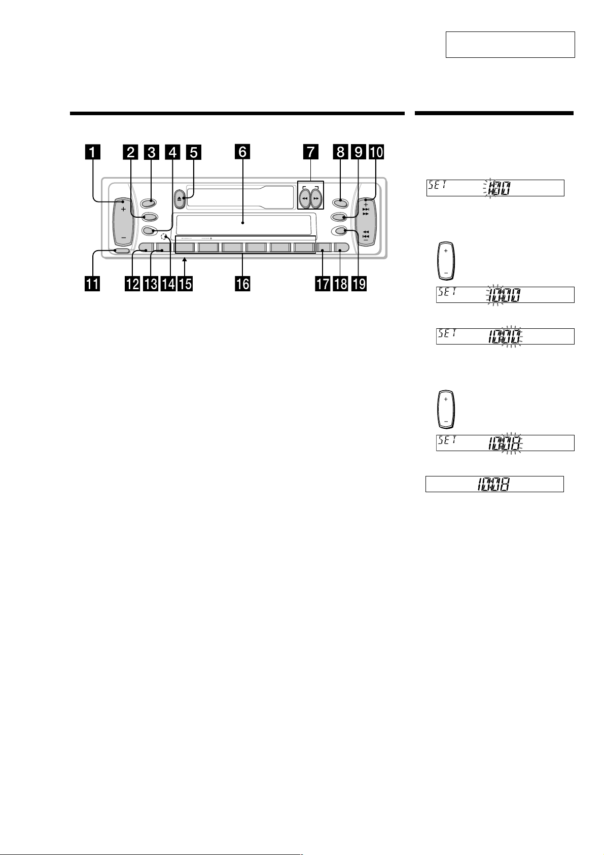
Location of controls
Setting the clock
The clock uses a 12-hour digital indication.
Example: To set the clock to 10:08
1 Press (DSPL) for two seconds.
The hour indication flashes.
1 Press either side of the volume button
to set the hour.
2 Press (SEL).
The minute indication flashes.
3 Press either side of the volume button
to set the minute.
2 Press (DSPL).
The clock starts.
After the clock setting is complete, the
display returns to normal playback mode.
to go forward
to go back
to go forward
to go back
SOURCE
SRC
MODE
SEL
RELEASE
Refer to the pages listed for details.
SENS
SECTION 1
GENERAL
DISC REP SHUF ATA
XR-CA330/CA340
This section is extracted from
instruction manual.
DIR
MBP
D-BASS
D
SEEK
AMS
OFF
654321
BTM DSPLATT
1 Volume +/– button 7
2 MODE button
During radio reception:
BAND select 8, 9
During CD/MD playback:
CD/MD unit select 12
3 SOURCE (TUNER/CD/MD) button
8, 9, 12
4 SEL (select) button 7, 10, 11, 12
5 Z (eject) button 7, 8, 9, 12
6 Display window
7 m/M (fast winding)/DIR (tape
transport direction change) buttons 7, 8
8 MBP (My Best sound Position) button
11
9 D-BASS button 11
q; SEEK/AMS +/– button 9, 13
Seek 9
Automatic Music Sensor 13
Manual search 13
qa RELEASE (front panel release) button
6, 14
qs ATT (attenuate) button 10
qd SENS button 9
qf RESET button (located on the front side
of the unit behind the front panel) 6
qg Frequency select switch (XR-CA340 only)
(located on the bottom of the unit)
See “Frequency select switch” in the
Installation/Connections manual.
qh Number buttons 8, 9, 10, 12, 13
During radio reception:
Preset number select 9
During tape playback:
(6) ATA 8
During CD/MD playback:
(1) DISC – 13
(2) DISC + 13
(3) REP 13
(4) SHUF 13
qj BTM button 8
qk DSPL (display mode change) button
7, 12
ql OFF button* 6
* Warning when installing in a car
without ACC (accessory) position on
the ignition key switch
Be sure to press (OFF) on the unit for two
seconds to turn off the clock display after
turning off the engine.
When you press (OFF) momentarily, the
clock display does not turn off and this
causes battery wear.
3
XR-CA330/CA340
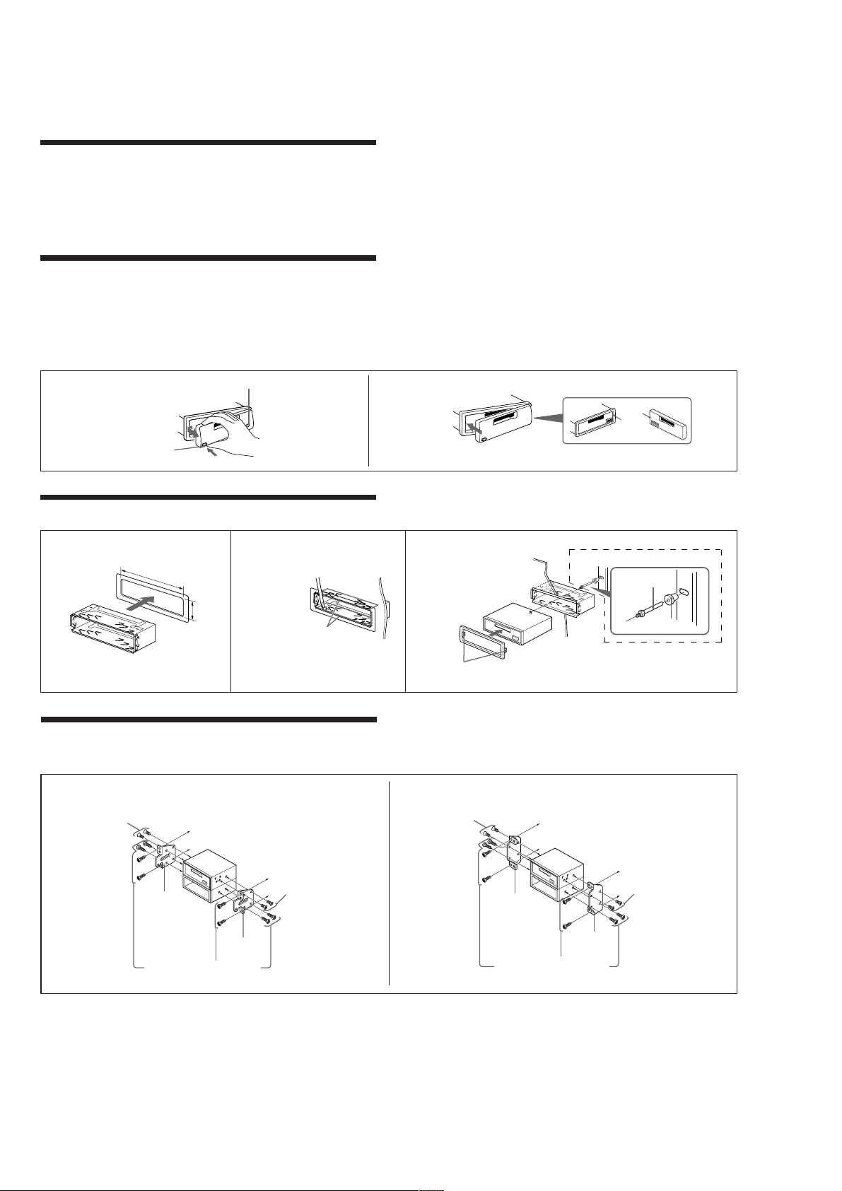
Installation
Precautions
•Choose the installation location carefully so that the unit will not interfere with normal driving.
•Avoid installing the unit in areas subject to dust, dirt, excessive vibration, or high temperatures, such as
in direct sunlight or near heater ducts.
•Use only the supplied mounting hardware for a safe and secure installation.
Mounting angle adjustment
Adjust the mounting angle to less than 20°.
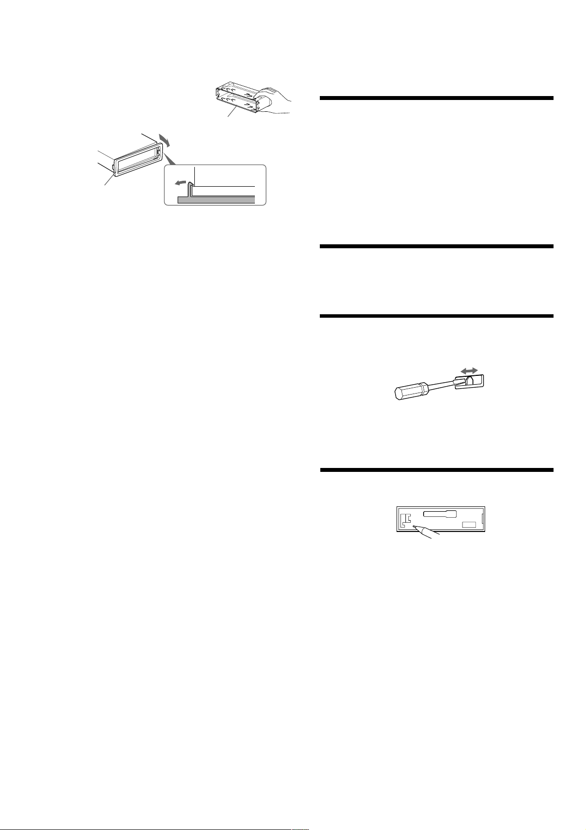
How to detach and attach the front panel
Before installing the unit, detach the front panel.
A
To detach
Before detaching the front panel, be sure to press (OFF). Press (RELEASE), then slide the front panel a
little to the left, and pull it off towards you.
B
To attach
Attach part A of the front panel to part B of the unit as illustrated and push the left side into position
until it clicks.
(OFF)
A
(RELEASE)
Mounting example (Installation in the dashboard)
B
A
B
123
182 mm
53 mm
Bend these claws outward for a tight
1
Mounting the unit in a Japanese car
You may not be able to install this unit in some makes of Japanese cars. In such a case, consult your Sony
dealer.
TOYOTA NISSAN
4
max. size M5 × 8 mm
Bracket
fit, if necessary.
to dashboard/centre console
4
Bracket
max. size M5 × 8 mm
With the UP marking up
4
max.size M5 × 8 mm
(XR-CA340 only)
Dashboard
5
Bracket
Fire wall
2
1
First attach 5 to the unit, then insert the unit into 1.
to dashboard/centre console
Bracket
3
4
max. size M5 × 8 mm
Existing parts supplied to your car
Note
To prevent malfunction, install only with the supplied screws 4.
4
Existing parts supplied to your car
XR-CA330/CA340
Cautions
•Cautionary notice for handling the bracket 1.
Handle the bracket carefully to avoid injuring your fingers.
•Remove the protection collar 5 before installing.
Release the catch lock as illustrated.
5
Connections
Cautions
1
•This unit is designed for negative earth 12 V DC operation only.
•Be careful not to pinch any wires between a screw and the body of the car or this unit or between any
moving parts such as the seat railing, etc.
•Before making connections, disconnect the earth terminal of the car battery to avoid short circuits.
•Connect the yellow and red power input leads only after all other leads have been connected.
•Be sure to connect the red power input lead to the positive 12 V power terminal which is energized
when the ignition key is in the accessory position.
•Run all earth wires to a common earth point.
•Connect the yellow cord to a free car circuit rated higher than the unit’s fuse rating. If you connect this
unit in series with other stereo components, the car circuit they are connected to must be rated higher
than the sum of the individual component’s fuse rating. If there are no car circuits rated as high as the
unit’s fuse rating, connect the unit directly to the battery. If no car circuits are available for connecting
this unit, connect the unit to a car circuit rated higher than the unit’s fuse rating in such a way that if the
unit blows its fuse, no other circuits will be cut off.
•Be sure to insulate any loose unconnected wires with electrical tape for safety.
•When installing a car without ACC (accessory) position on the ignition key switch, connect the red
power input lead to the +12 V power terminal which is energized at all times with the yellow lead.
Warning when installing in a car without ACC (accessory) position on
the ignition key switch
Be sure to press (OFF) on the unit for two seconds to turn off the clock display after turned off the
engine.
When you press (OFF) momentarily, the clock display does not turn off and this causes battery wear.
Frequency select switch (XR-CA340 only)
The AM (FM) tuning interval is factory-set to the 9 K (50 K) position. If the frequency allocation system of
your country is based on 10 kHz (200 kHz) interval, set the switch on the bottom of the unit to the 10 K
(200 K) position before making connections.
Change the position with a jeweler’s screwdriver, etc.
Note
When you change the position of the switch, be sure to press the reset buttons after the connections are
completed.
Reset button
When the installation and connections are over, be sure to press the reset button with a ballpoint pen, etc.
5
XR-CA330/CA340
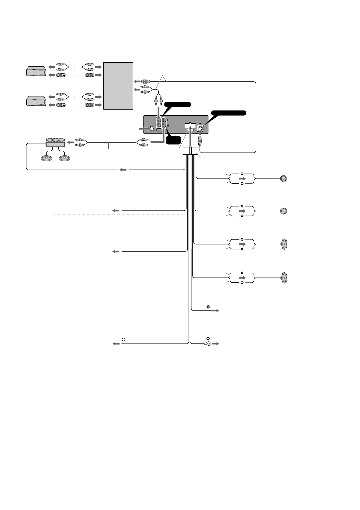
Connection diagram
Supplied with the CD/MD changer
Source selector
(not supplied)
Supplied with the XA-C30
BUS AUDIO IN
BUS CONTROL IN
RCA pin cord (not supplied)
to AMP REMOTE IN of the optional power amplifier
This connection is only for ampilifiers. Connecting any other system may
damage the unit.
XR-CA340 only
to the interface cable of a car telephone
to the power aerial control lead or power supply lead of aerial booster
amplifier
Notes
• It is not necessary to connect this lead if there is no power aerial or aeria
booster, or with a manually-operated telescopic aerial.
• When your car has a built-in FM/AM aerial in the rear/side glass, see
“Notes on the control and power supply leads.”
from a car aerial
AMP REM
Max. supply current 0.3 A
ATT
ANT REM
Max. supply current 0.1 A
BUS
AUDIO
AUDIO IN
OUT
AUDIO
OUT
Fuse (10 A)
Blue/white striped
Sky blue
Blue
7
White
White/black striped
Grey/black striped
Green
Green/black striped
Purple
Purple/black striped
Left
Grey
Right
Left
Right
to the +12 V power terminal which is energized at the accessory position
of the ignition key switch
Notes
• If there is no accessory position, connect to the +12 V power (battery)
terminal which is energized at all times.
Be sure to connect the black earth lead to it first.
• When your car has a built-in FM/AM aerial in the rear/side glass, see
“Notes on the control and power supply leads.”
Notes on the control and power supply leads
• The power aerial control lead (blue) supplies +12 V DC when you turn on the unit.
• When your car has a built-in FM/AM aerial in the rear/side glass, it is necessary to connect the power aerial
control lead (blue) or the accessory power input lead (red) to the power terminal of the existing aerial booster.
For details, consult your dealer.
• A power aerial without a relay box cannot be used with this unit.
Memory hold connection
When the yellow power input lead is connected, power will always be supplied to the memory circuit even when
the ignition switch is turned off.
Notes on speaker connection
• Before connecting the speakers, turn the unit off.
• Use speakers with an impedance of 4 to 8 ohms, and with adequate power handling capacities. Otherwise, the
speakers may be damaged.
• Do not connect the terminals of the speaker system to the car chassis, and do not connect the terminals of the
right speaker with those of the left speaker.
• Do not attempt to connect the speakers in parallel.
• Do not connect any active speakers (with built-in amplifiers) to the speaker terminals of the unit. Doing so may
damage the active speakers. Be sure to connect passive speakers to these terminals.
Yellow
Red
Black
to the +12 V power terminal which is energized at all times
Be sure to connect the black earth lead first.
to a metal place in the car
First connect the black earth lead, then connect the yellow and red
power input leads.
6
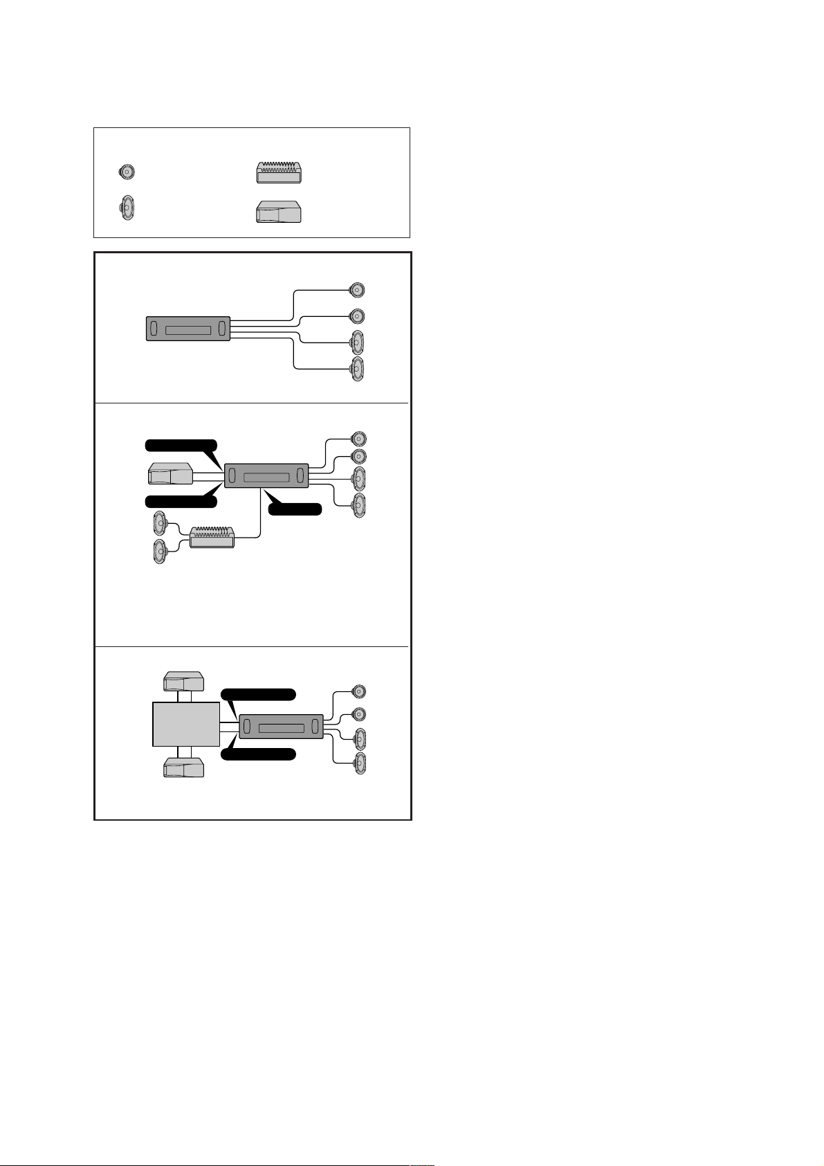
Connection example
Equipment used in illustrations (not supplied)
XR-CA330/CA340
Power amplifierFront speakers
Rear speakers
CD/MD changer
A
B
BUS AUDIO IN
BUS CONTROL IN
Notes
• Be sure to connect the earth cord before connecting the amplifier.
• If you connect an optional power amplifier and do not use the built-in amplifier, the beep sound will
be deactivated.
AUDIO OUT
C
BUS AUDIO IN
Source selector
(not supplied)
BUS CONTROL IN
For connecting two or more changers, the source selector XA-C30 (optional) is necessary.
7
XR-CA330/CA340
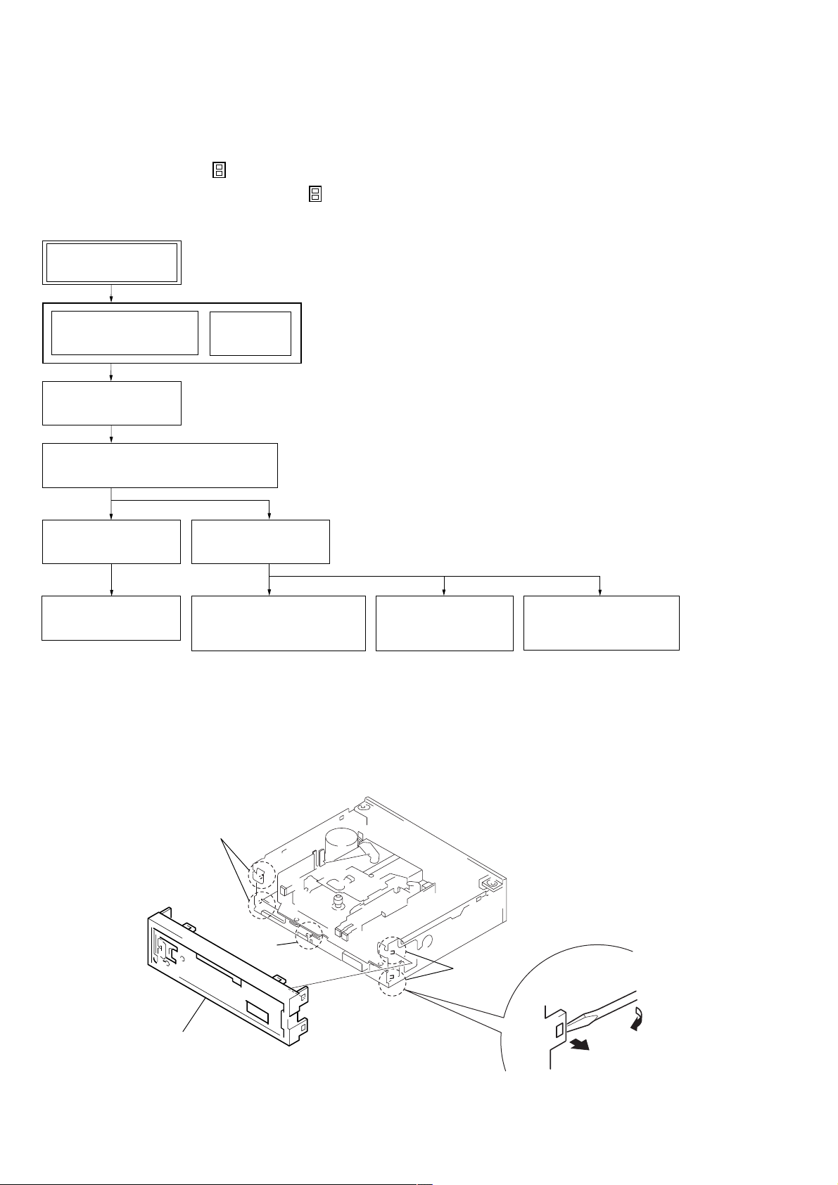
SECTION 2
DISASSEMBLY
• This set can be disassembled in the order shown below.
2-1. DISASSEMBLY FLOW
Note 1: The process described in can be performed in any order.
Note 2: Without completing the process described in , the next process can not be performed.
Note 3: Illustration of disassembly is omitted.
SET
FRONT PANEL SECTION
(Note 3)
2-2. SUB PANEL
(Page 8)
2-3. MECHANISM DECK (MG-36SZ12-32)
(Page 9)
2-4. MAIN BOARD
(Page 9)
2-5. HEAT SINK
(Page 10)
Note: Follow the disassembly procedure in the numerical order given.
COVER
(Note 3)
2-6. BRACKET (MD)
(Page 10)
2-7. MOTOR
(CAPSTAN/REEL) (M901)
(Page 11)
2-2. SUB PANEL
2-8. MAIN BELT,
SUB BELT (C)
(Page 11)
2-9. HEAD
(PLAYBACK) (HP901)
(Page 12)
1
two claws
1
claw
1
two claws
2
sub panel
8
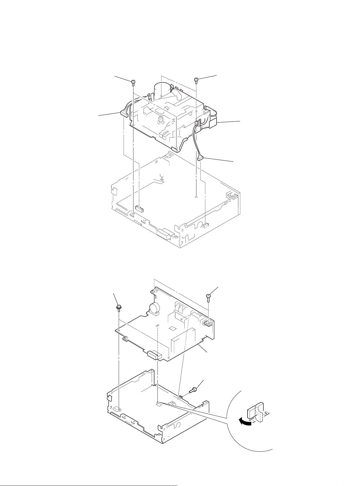
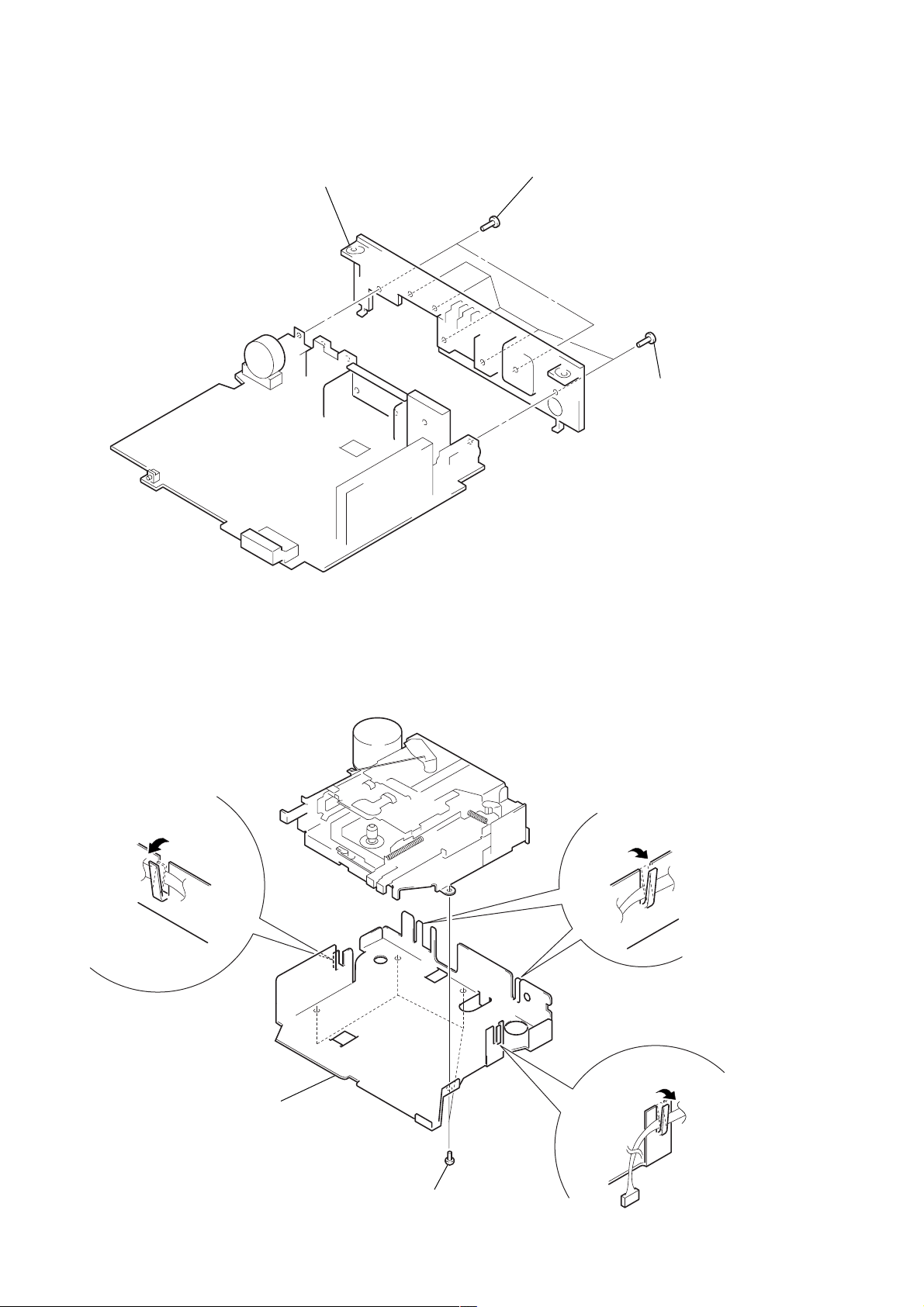
2-3. MECHANISM DECK (MG-36SZ12-32)
2
two screws
1
connector
(CN350)
(BTP2.6
×
6)
2
two screws
(BTP2.6
×
6)
3
mechanism deck (MG-36SZ12-32)
1
connector
(CN300)
XR-CA330/CA340
2-4. MAIN BOARD
2
two ground point screws
(PTT2.6
3
two screws
×
6)
4
3
(BTP2.6
main board
screw
(BTP2.6
×
10)
×
10)
1
claw
9
XR-CA330/CA340
2-5. HEAT SINK
2
heat sink
1
two screws
(PTT2.6
×
10)
1
five screws
(PTT2.6
×
10)
2-6. BRACKET (MD)
1
claw
3
bracket (MD)
1
claw
10
2
four screws
(B2.6
1
claw
×
4)
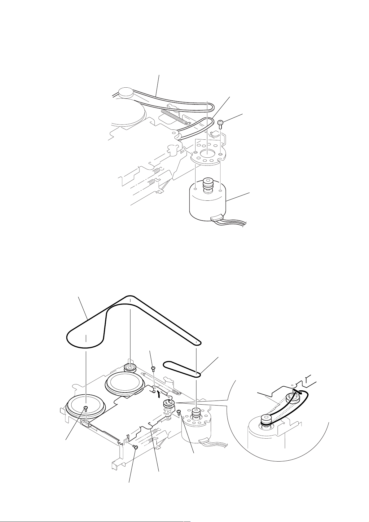
2-7. MOTOR (CAPSTAN/REEL) (M901)
2
main belt
3
sub belt (C)
1
two screws
(P2 × 2.5)
4
motor (capstan/reel) (M901)
XR-CA330/CA340
2-8. MAIN BELT, SUB BELT (C)
1
main belt
2
screw
(PTP2
Note :When installing motor,
adjust the screw and
screw hole of motor.
×
3)
4
sub belt (c)
2
screw
(PTP2 × 3)
2
screw
(PTP2 × 3)
A
2
screw
(PTP2 × 3)
3
Lift up the bottom BKT (TS)
in the direction of arrow
(as far as the belt can be removed).
A
11
 Loading...