

Sony XR-CA320X,XR-CA320 Installation/connections Manual
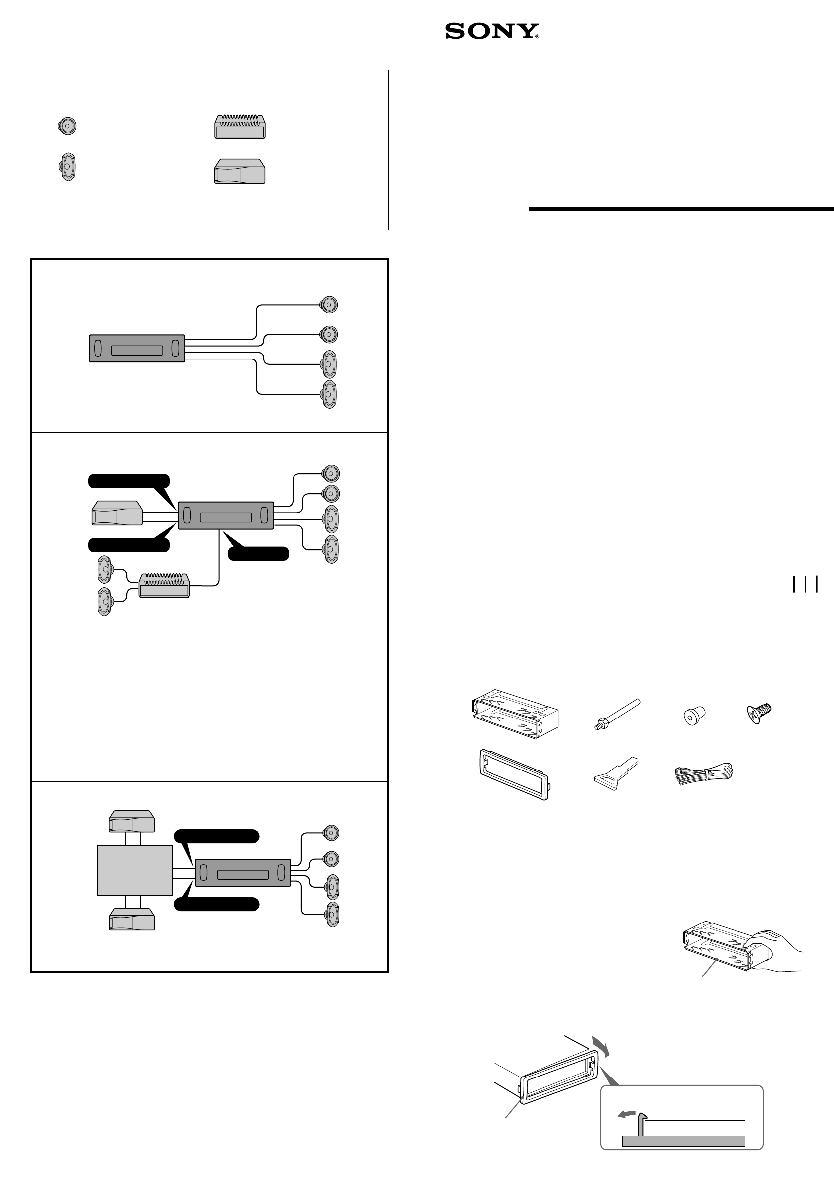
Connection example
Ejemplo de conexiones
‰u‚ ‡s– „ˇ¤
Equipment used in illustrations (not supplied)
Equipo utilizado en las ilustraciones (no suministrado)
„ˇ⁄⁄¤ˇ¥˛“”‡]‡˘¡] L“ –a¡^
Front speakers
Altavoces delanteros
«e·›`n „
Power amplifier
Amplificador de potencia
¥\†v'æ⁄j „
3-225-234-31 (1)
FM/AM
Rear speakers
Altavoces traseros
«Æ·›`n „
For connecting two or more changers, the source selector XA-C30 (optional) is necessary.
Cuando desee conectar dos o más cambiadores, necesitará un selector de fuente XA-C30 (opcional).
›Y›n‡s– 2 »O'˛ 2 »O¥H⁄W·«”— fi ¡A«K¶•¤ˇ¥˛› •‰¿ „ XA-C30¡]¿ `˚¥ ¡^¡C
CD/MD changer
Cambiador de CD/MD
CD/MD ·«”—
A
Cassette
Car Stereo
Installation/Connections
Instalación/Conexiones
ƒw‚¸¡ ‰u‚ ⁄§‡s–
B
BUS AUDIO IN
BUS CONTROL IN
Notes
• Be sure to connect the earth cord before connecting the amplifier.
• If you connect an optional power amplifier and do not use the built-in amplifier, the beep sound will
be deactivated.
Notas
• Asegúrese de conectar primero el cable de puesta a masa antes de realizar la conexión al
amplificador.
• Si conecta un amplificador de potencia opcional y no utiliza el incorporado, los pitidos se
desactivarán.
ø
•
¨¥†ƒb– 'æ⁄j „⁄§«e‡s– ƒa‰u
•
ƒp“G–z‡s– ⁄F¿ `˚¥ “”¥\†v'æ⁄j „ƒ ⁄£¤ˇ¥˛⁄”‚¸“”'æ⁄j „¡A–N L„˚`n¥\fl
¡C
AUDIO OUT
¡C
XR-CA320X
XR-CA320
Sony Corporation 2001
Parts list
Lista de componentes
„s¥ ⁄@˜ “
The numbers in the list are keyed to those in the instructions.
Los números de la lista corresponden a los de las instrucciones.
„ˇ¥ …˘ƒr»P»¡'œfi ⁄⁄“”…˘ƒr‹O⁄@›P“”¡C
1
5
2
67
3
4
× 4
C
Source selector
Selector de fuente
› •‰¿ „
BUS AUDIO IN
BUS CONTROL IN
The release key 6 is used for dismounting the unit. See the operating instructions manual for details.
La llave de liberación 6 se utiliza para desmontar la unidad. Con respecto a los detalles, consulte el
manual de instrucciones.
›Y›n§ ¥» ¥ 'T'w⁄§‡B' ¤ł⁄U¤ fi ¡A‰—¤ˇ¥˛ˆP¶}¥˛“”˘_ ˝ 6¡C‚ † ‰—‹ ¤ˇ¥˛»¡'œfi ¡C
Cautions
• Cautionary notice for handling the bracket 1.
Handle the bracket carefully to avoid injuring your fingers.
• Remove the protection collar 5 before installing.
Precauciones
•Advertencia sobre la manipulación del soporte 1.
Tenga mucho cuidado al manipular el soporte para evitar
posibles lesiones en los dedos.
•Retire el collar de protección 5 antes de realizar la
instalación.
“‘•N
•† ˚‚¸¤ł⁄ ‹[ 1 fi ¡A‰—flS§O“‘•N§O¶¸¤⁄«¡C
•ƒw‚¸«e¡A¥ –N«O¯@fi ‹[ 5 ¤œ¥X¡C
Release the catch lock as illustrated.
Suelte el enganche como se muestra en la
ilustración.
ƒp„ˇ' ¥ ¡A† ¶}´Œ” •fƒ'¡C
1
5
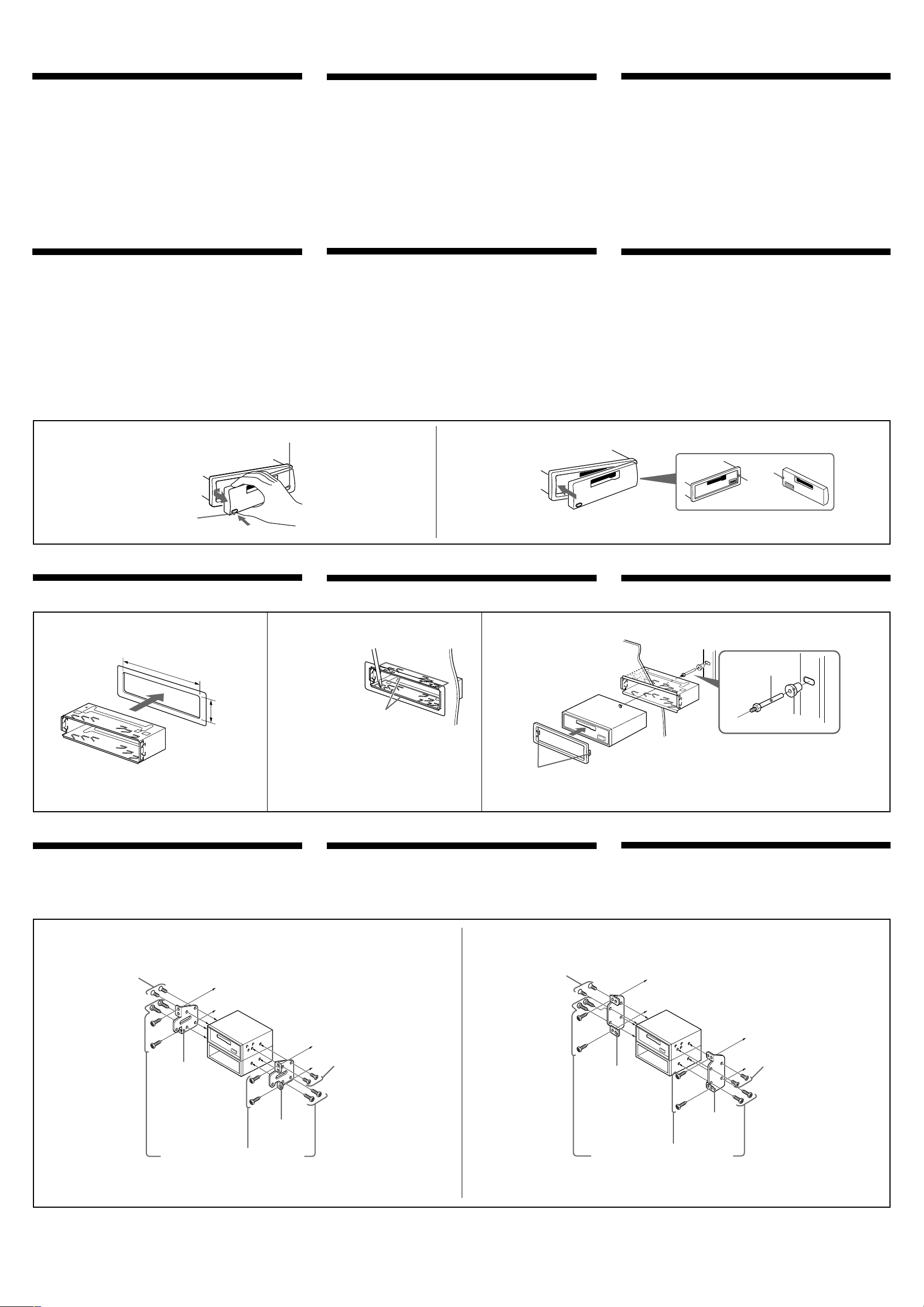
Installation Instalación
ƒw‚¸
Precautions
•Choose the installation location carefully so that the unit will not
interfere with normal driving.
•Avoid installing the unit in areas subject to dust, dirt, excessive
vibration, or high temperatures, such as in direct sunlight or near
heater ducts.
•Use only the supplied mounting hardware for a safe and secure
installation.
Mounting angle adjustment
Adjust the mounting angle to less than 20°.
How to detach and attach the front panel
Before installing the unit, detach the front panel.
A To detach
Before detaching the front panel, be sure to press (OFF). Press
(RELEASE), then slide the front panel a little to the left, and pull it off
towards you.
B To attach
Attach part A of the front panel to part B of the unit as illustrated
and push the left side into position until it clicks.
Precauciones
•Elija cuidadosamente el lugar de montaje de forma que la unidad
no interfiera las funciones normales de conducción.
•Evite instalar la unidad donde pueda quedar sometida a altas
temperaturas, como a la luz solar directa o al aire caliente de
calefacción, o a polvo, suciedad, o vibraciones excesivas.
•Para realizar una instalación segura y firme, utilice solamente la
ferretería de montaje suministrada.
Ajuste del ángulo de montaje
Ajuste el ángulo de montaje a menos de 20°.
Forma de extraer e instalar el panel frontal
Antes de instalar la unidad, extraiga el panel frontal.
A Para extraerlo
Antes de extraer el panel frontal, asegúrese de presionar (OFF).
Presione (RELEASE), deslice el panel ligeramente hacia la izquierda
y tire de él hacia fuera.
B Para instalarlo
Coloque el orificio A del panel frontal en el eje B de la unidad,
como se muestra en la ilustración, y después presione la parte
izquierda hasta que encaje.
¤ˇ¥˛«e¶•“‘•N
•¥» ‰—'æƒb⁄£§«ˆ“¥q r p⁄§‡B¡C
•` §K–N¥» 'æƒb “•¯⁄§‡B¡Aƒp¶§¥œ“‰– • fig¡B•xfi «e¡B'˛ƒ
ƒh¡B¯…¶ˆ¡A¥H⁄˛•¥' ¤ _ ˚ ¥ƒa⁄Ł¡C
•‹ ⁄Fƒw¥ ⁄˛¥i a“”ƒw‚¸ _¤£¡A››¤ˇ¥˛“ –a“”‡¡¥ ¡C
ƒw‚¸¤⁄« ⁄§‰ ª
‰—ƒb 20 « ¥H⁄”‰ ªƒw‚¸¤⁄« ¡C
ƒpƒ ' ¤ł'M‚¸ t«e“O
ƒw‚¸¥» ⁄§«e¡A‰—¥ ' ¤ł«e“O¡C
A '¤ł
' ¤ł«e“O⁄§«e¡A ¨¥†« ⁄U (OFF) ` ¡C M«Æ¡A« ⁄U (RELEASE) `¡A
–N«e“O y•LƒV¥“ˆ •˘ ˚¡A·´–zƒ ⁄v“”⁄ŁƒV' ¥X¡C
B ‚¸ t
ƒp„ˇ' ¥ ¡A–N«e“O“” A ‡B„ •˙¥» “” B ‡B¡A M«Æ–N¥“ …– ⁄J“‰ƒ
¯¥¤ ‡ ‡ `n¡C
(OFF)
A
(RELEASE)
Installation in the dashboard
Instalación en el salpicadero ƒw‚¸ƒb» ¿ “O‚
B
123
182 mm
53 mm
1
Bend these claws outward for a tight
fit, if necessary.
Si es necesario, doble estas uñas hacia
fuera para que encaje firmemente.
›Yƒ‡¥†›n¡A«h¥i¯sƒ–‡o¤˙¥d⁄ ¡C
Dashboard
Salpicadero
»¿“O
5
With the UP marking up
Con la marca UP hascia arriba
¤ˇ ø "UP"ƒr…¸⁄§›–ƒV⁄W¡C
A
B
Fire wall
Panel cortafuegos
¤⁄ı
2
1
First attach 5 to the unit, then insert the unit into 1.
En primer lugar, fije 5 a la unidad y, a continuación, inserte ésta en 1.
›”¥ –N 5 ‚¸¤ „⁄W¡A M«Æ–N „·¡⁄J 1¡C
3
Mounting the unit in a Japanese car
You may not be able to install this unit in some makes of Japanese
cars. In such a case, consult your Sony dealer.
Montaje de la unidad en un automóvil
japonés
Es posible que no pueda instalar esta unidad en algunos automóviles
japoneses. En tal caso, consulte a su proveedor Sony.
TOYOTA NISSAN
4
max. size M5 × 8 mm
Tamaño máx.: M5 × 8mm
‡ ⁄j⁄ ⁄o M5¡ 8 mm
Bracket
Soporte
ƒ«‹[
Existing parts supplied to your car
Piezas existentes suministradas con su
automóvil
“ –a' ¤T¤fi“”‡¡¥
to dashboard/centre console
al salpicadero/consola central
ƒ » ¿ “O¢A⁄⁄¥¡––¤ ‰c
4 max. size M5 × 8 mm
Tamaño máx.: M5 × 8mm
‡ ⁄j⁄ ⁄o M5¡ 8 mm
Bracket
Soporte
ƒ«‹[
4 max.size M5 × 8 mm
Tamaño máx.: M5 × 8mm
‡ ⁄j⁄ ⁄oM5 ¡ 8 mm
–N¥» ƒw‚¸' ⁄Ø¥»†£¤T¤fi‚
ƒ‡“”⁄Ø¥»†£¤T¤fi⁄£fl ƒw‚¸¥» ¡Aƒ„fi ¡A‰—‹¢‚ • ƒa“” Sony ‚g P ¡C
to dashboard/centre console
al salpicadero/consola central
ƒ » ¿ “O¡ ⁄⁄¥¡––¤ ‰c
Bracket
Soporte
ƒ«‹[
Bracket
Soporte
ƒ«‹[
Existing parts supplied to your car
Piezas existentes suministradas con su
automóvil
“ –a' ¤T¤fi“”‡¡¥
4 max. size M5 × 8 mm
Tamaño máx.: M5 × 8mm
‡ ⁄j⁄ ⁄o M5¡ 8 mm
Note
To prevent malfunction, install only with the supplied screws 4.
Nota
Para evitar un funcionamiento incorrecto, utilice sólo los tornillos
suministrados 4.
ø
‹ ¤ ⁄ o¥˝‹G» ¡Aƒw‚¸fi ¥ufl ¤ˇ¥˛“ –a“”`‡ • 4¡C
 Loading...