

Sony XRC-9100 Service manual
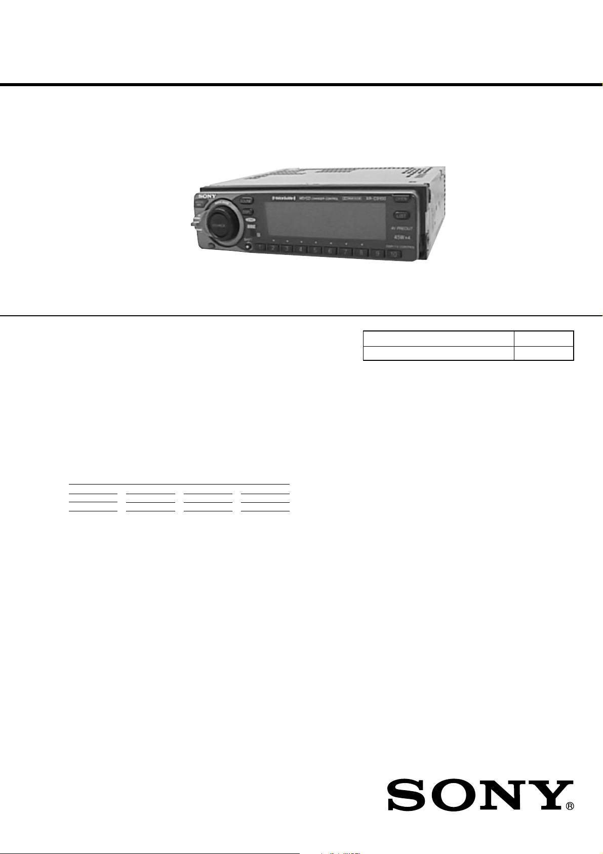
XR-C9100
SERVICE MANUAL
Ver 1.1 2001. 08
SPECIFICATIONS
AUDIO POWER SPECIFICATIONS (US model)
POWER OUTPUT AND TOTAL HARMONIC DISTORTION
19 watts per channel minimum continuous average power into
4 ohms, 4 channels driven from 20 Hz to 20 kHz with no more than
1 % total harmonic distortion.
US Model
E Model
Model Name Using Similar Mechanism XR-C8100
Tape Transport Mechanism Type MG-25D-136
Other specifications
Cassette player section
Tape track 4-track 2-channel stereo
Wow and flutter 0.08 % (WRMS)
Frequency response 30 - 20,000 Hz
Signal-to-noise ratio
Cassette type Dolby B NR Dolby C NR Dolby NR off
TYPE II, IV 67 dB 73 dB 61 dB
TYPE I 64 dB 70 dB 58 dB
Tuner section
FM
Tuning range US model:
87.5 -107.9 MHz
E model:
FM tuning interval:
50 kHz / 200 kHz
switchable
87.5 - 108.0 MHz
(at 50 kHz step)
87.5 - 107.9 MHz
(at 200 kHz step)
Antenna terminal External antenna connector
Intermediate frequency 10.7 MHz
Usable sensitivity 8 dBf
Selectivity 75 dB at 400 kHz
Signal-to-noise ratio 65 dB (stereo),
68 dB (mono)
Harmonic distortion at 1 kHz
0.7% (stereo),
0.4% (mono)
Separation 35 dB at 1 kHz
Frequency response 30 - 15,000 Hz
AM
Tuning range US model:
530 - 1,710 kHz
E model:
AM tuning interval:
9 kHz / 10 kHz switchable
531 - 1,602 kHz
(at 9 kHz step)
530 - 1,710 kHz
(at 10 kHz step)
Antenna terminal External antenna connector
Intermediate frequency 10.71 MHz / 450 kHz
Sensitivity 30 µV
Power amplifier section
Outputs Speaker outputs
(sure seal connectors)
Speaker impedance 4 - 8 ohms
Maximum power output 45 W × 4 (at 4 ohms)
– Continued on next page –
9-925-992-12
2001H0400-1
© 2001. 8
FM/AM CASSETTE CAR STEREO
Sony Corporation
e Vehicle Company
Shinagawa Tec Service Manual Production Group
– 1 –

General
Outputs Line outputs (2)
Tone controls Bass ±8 dB at 100 Hz
Power requirements 12 V DC car battery
Dimensions Approx. 178 × 50 × 180 mm
Mounting dimensions Approx. 182 × 53 × 160 mm
Mass Approx. 1.5 kg (3 lb. 5 oz.)
Supplied accessories Rotary commander RM-X4S (1)
Design and specifications are subject to change without
notice.
Subwoofer output (1)
Power antenna relay
control lead
Power amplifier control
lead
Telephone ATT contr ol
lead
Illumination control lead
Treble ±8 dB at 10 kHz
(negative ground)
1
(7
(w/h/d)
1
(7
(w/h/d)
Wireless remote
RM-X47 (1) (E model)
Parts for installation and
connections (1 set)
Front panel case (1)
/
× 2 × 7
8
/
× 2
4
1
/
in.)
8
1
3
/
× 6
/
in.)
8
8
Dolby noise reduction manufactured under license from Dolby Laboratories Licensing Corporation.
“DOLBY” and the double-D symbol a are trademarks of Dolby
Laboratories Licensing Corporation.
Notes on Chip Component Replacement
• Never reuse a disconnected chip component.
• Notice that the minus side of a tantalum capacitor may be
damaged by heat.
TABLE OF CONTENTS
1. GENERAL
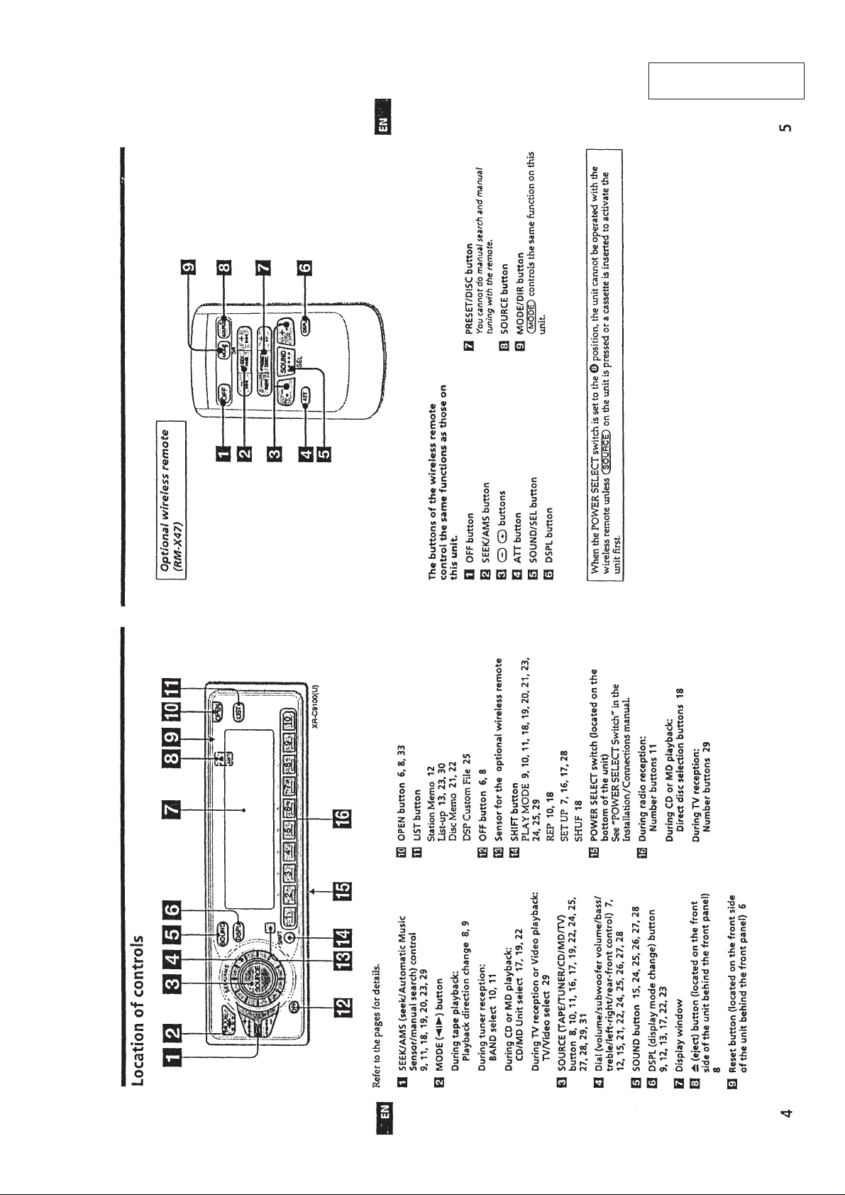
Location of Controls...............................................................3
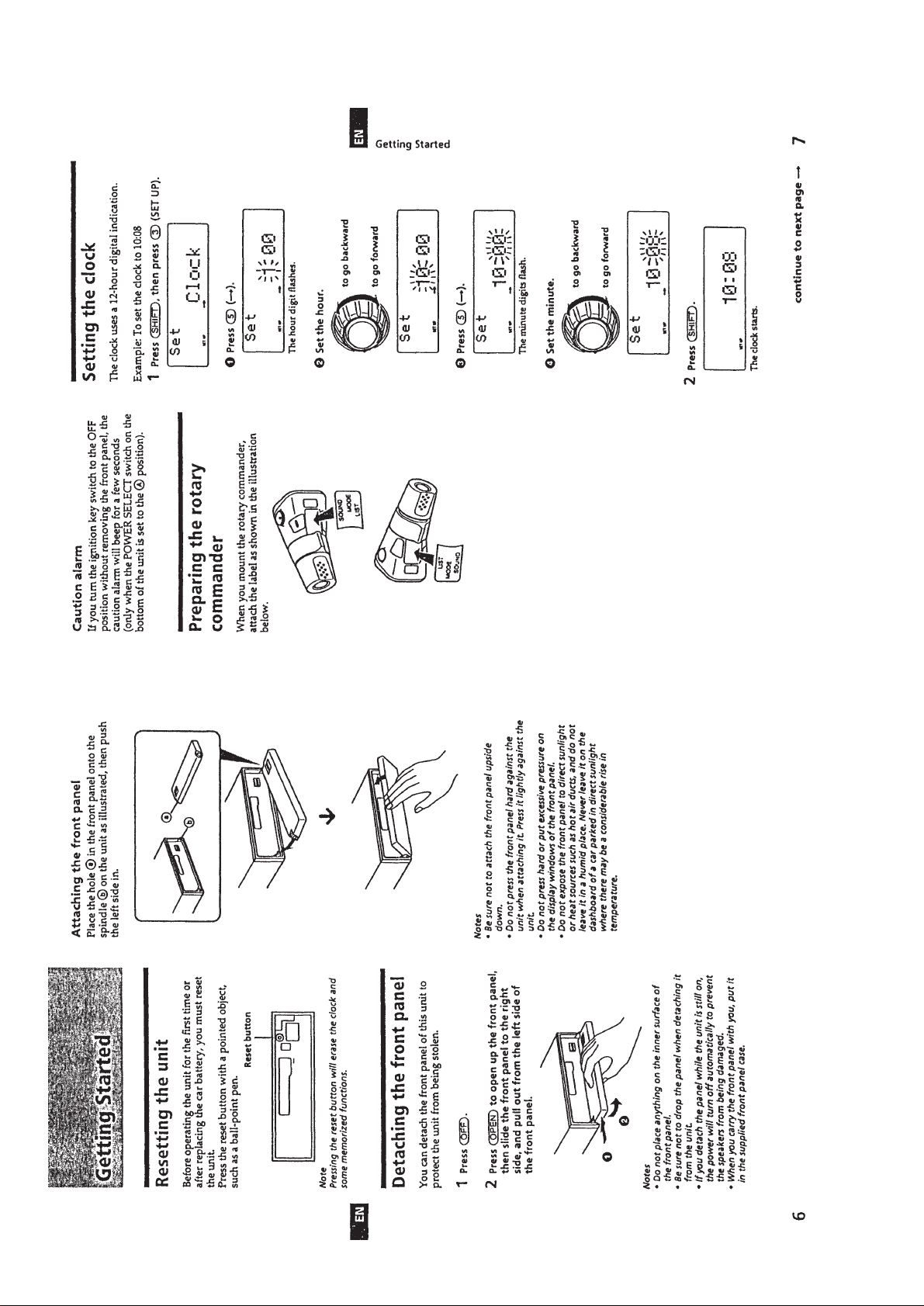
Getting Started........................................................................4
Setting the Clock ....................................................................4
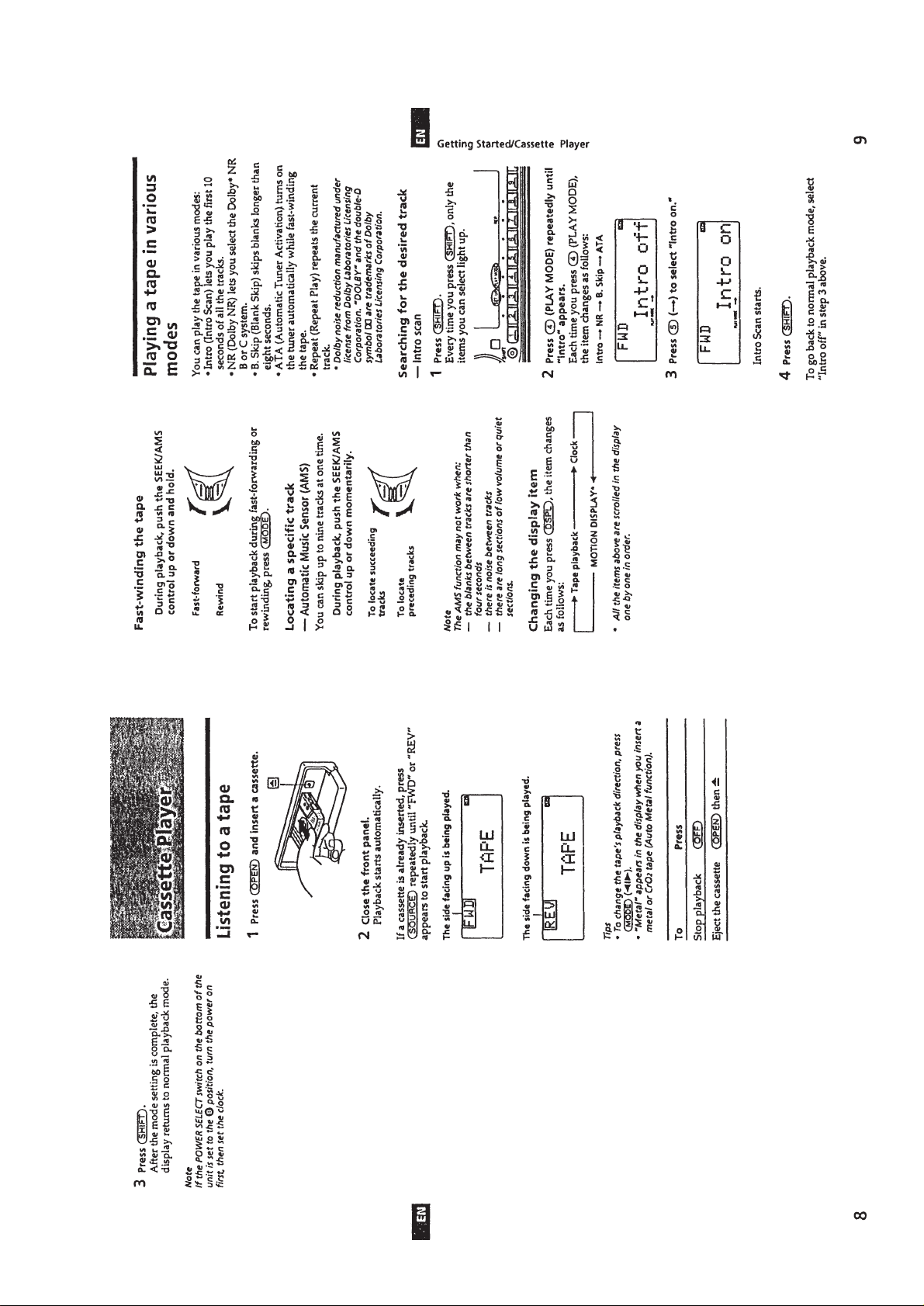
Cassette Player .......................................................................5
Radio ......................................................................................6
Other Functions ......................................................................7
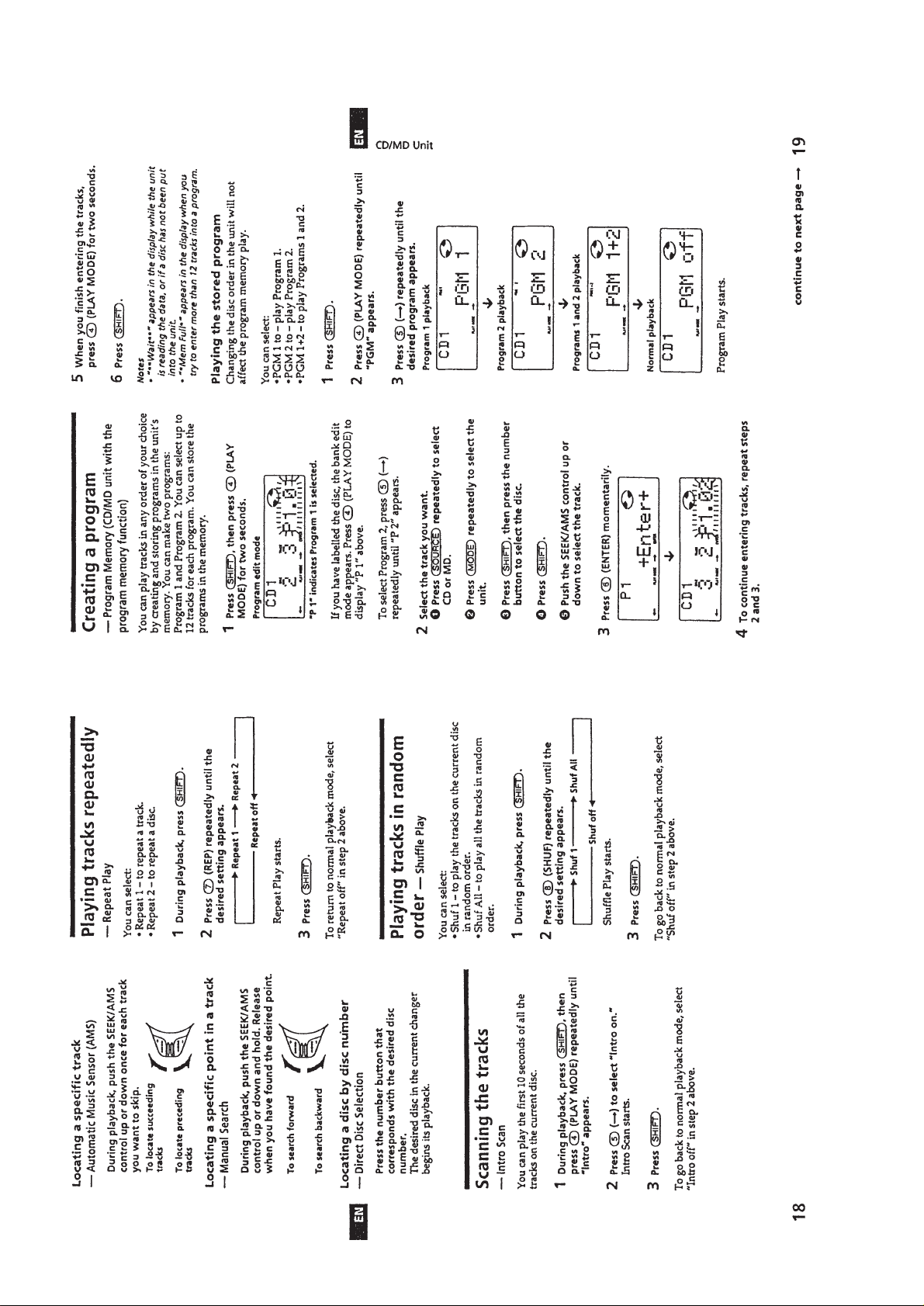
CD/MD Unit ...........................................................................9
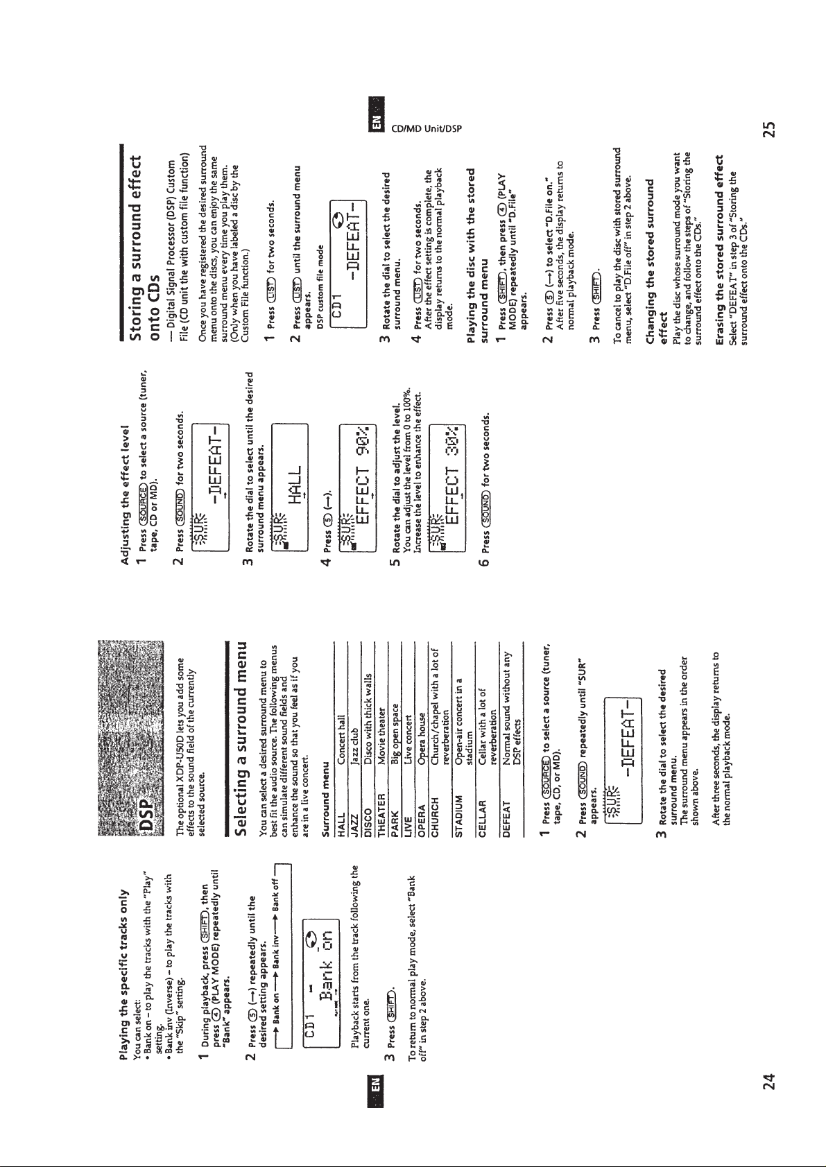
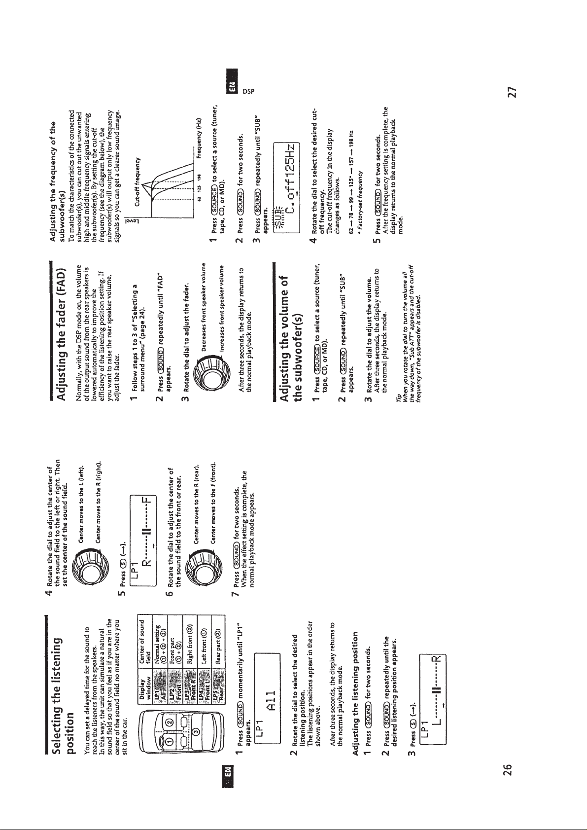
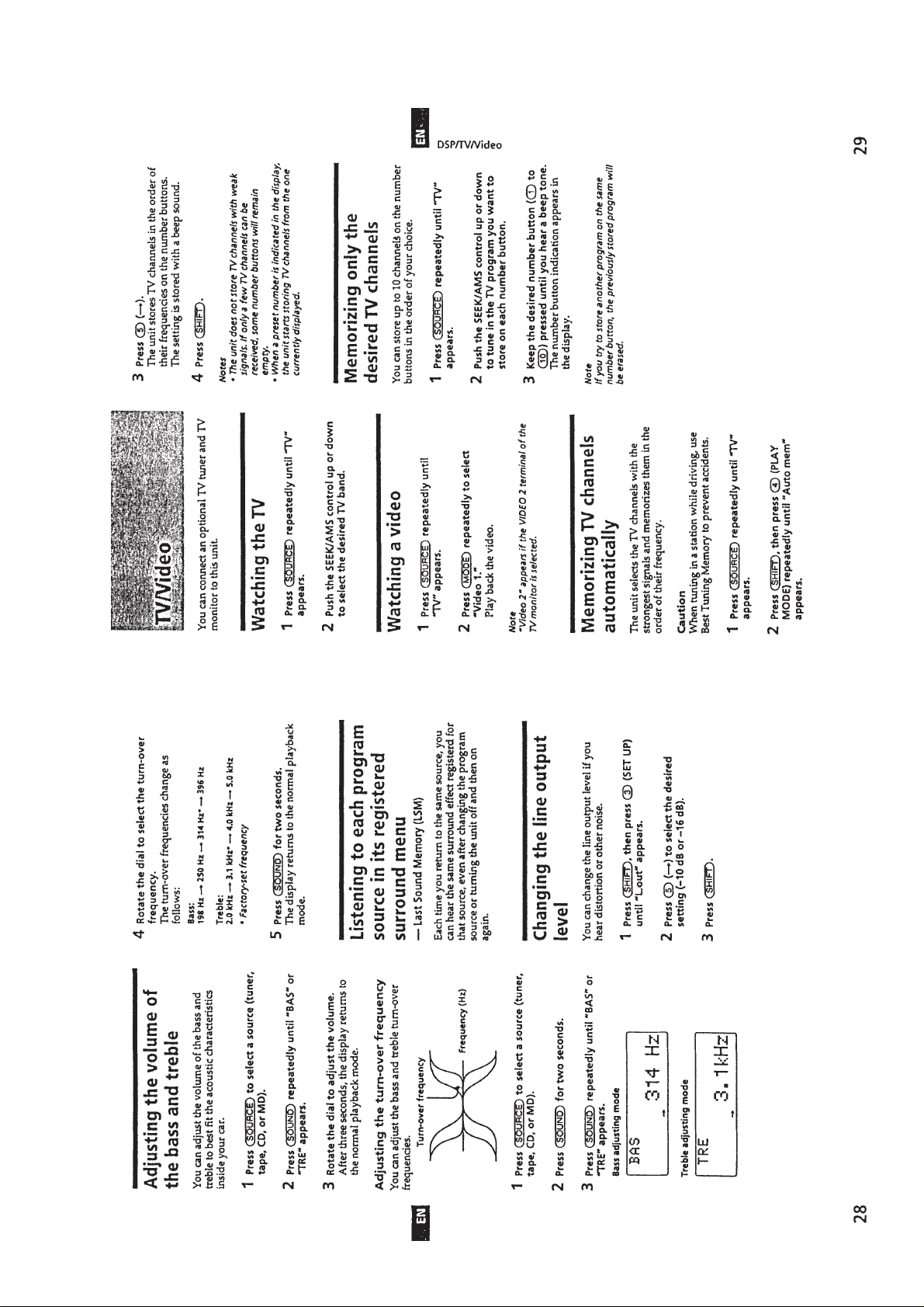
DSP.......................................................................................13
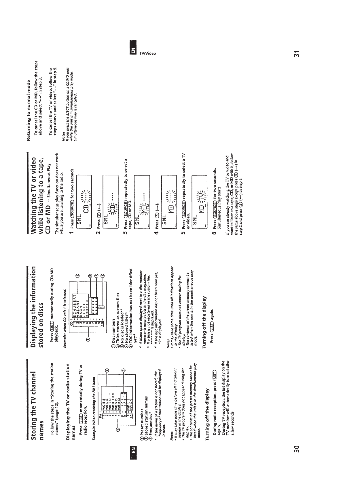
TV/Video ..............................................................................15
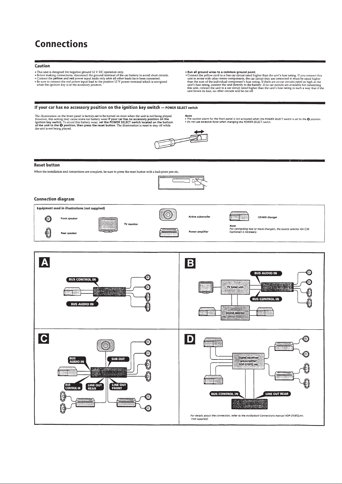
Connections ..........................................................................17
2. DISASSEMBLY
2-1. Cover ................................................................................ 19
2-2. Front Panel Assy ..............................................................19
2-3. Sub Panel Assy ................................................................. 20
2-4. Mechanism Deck..............................................................20
2-5. Main Board ...................................................................... 21
2-6. Heat Sink .......................................................................... 21
3. ASSEMBLY OF MECHANISM DECK
Housing ................................................................................22
Arm (Suction) .......................................................................22
Lever (LDG-A) / (LDG-B)...................................................23
Gear (Loading FT)................................................................23
Guide (C) .............................................................................. 24
Mounting Position of Capstan/Reel Motor (M901) ............. 24
4. MECHANICAL ADJUSTMENTS...........................25
5. ELECTRICAL ADJUSTMENTS
Tape Section .........................................................................25
Tuner Section........................................................................26
6. DIAGRAMS
6-1. IC Pin Description............................................................30
6-2. Block Diagram –Tape Section– ....................................... 33
6-3. Block Diagram –Main Section–.......................................35
6-4. Printed Wiring Boards –Main Section– ...........................38
6-5. Schematic Diagram –Main Section–................................43
6-6. Printed Wiring Board –Display Section– ......................... 48
6-7. Schematic Diagram –Display Section–............................50
7. EXPLODED VIEWS
7-1. Chassis Section ................................................................ 56
7-2. Front Panel Section .......................................................... 57
7-3. Mechanism Deck Section.................................................58
8. ELECTRICAL PARTS LIST ...................................59
– 2 –
SECTION 1
GENERAL
This section is extracted
from instruction manual.
– 3 –
– 4 –
– 5 –
– 6 –
– 7 –
– 8 –
– 9 –
– 10 –
– 11 –
– 12 –
– 13 –
– 14 –
– 15 –
– 16 –
– 17 –

– 18 –
SECTION 2
DISASSEMBLY
Note : Follow the disassembly procedure in the numerical order given.
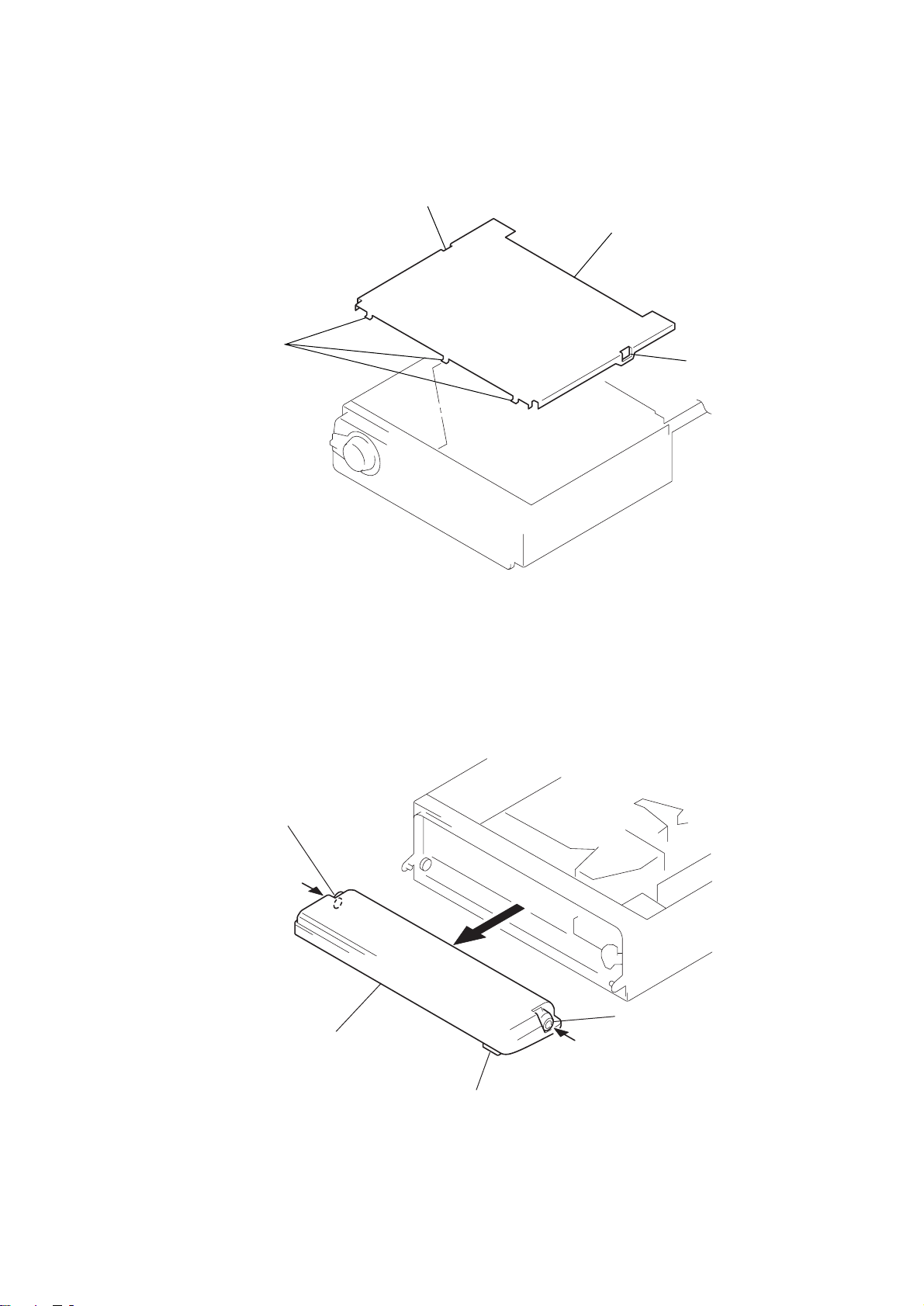
2-1. COVER
1
claw
3
claws
4
cover
2
claw
2-2. FRONT PANEL ASSY
3
Push the bearing (L).
4
front panel assy
1
Push the button (open).
2
Push the bearing (R).
– 19 –

0
)
2-3. SUB PANEL ASSY
3
PTT 2.6x6
4
2
PTT 2.6x6
claws
8
sub panel assy
5
claw
6
1
PTT 2.6x6
CN802
7
CN50
2-4. MECHANISM DECK
2
CN201
4
mechanism deck
1
screws
(2.6x6) (C TIGHT
3
CN250
– 20 –
 Loading...