

Sony XRC-8200 Service manual
XR-C8200
SERVICE MANUAL
For RM-X2S (Remote Commander),
please refer to RM-X2S/X3S Service
Manual (9-960-039-∏) previously issued.
Dolby noise reduction manufactured under license
form Dolby Laboratories Licensing Corporation.
“DOLBY” and the double-D symbol a are trademarks of Dolby Laboratories Licensing Corporation.
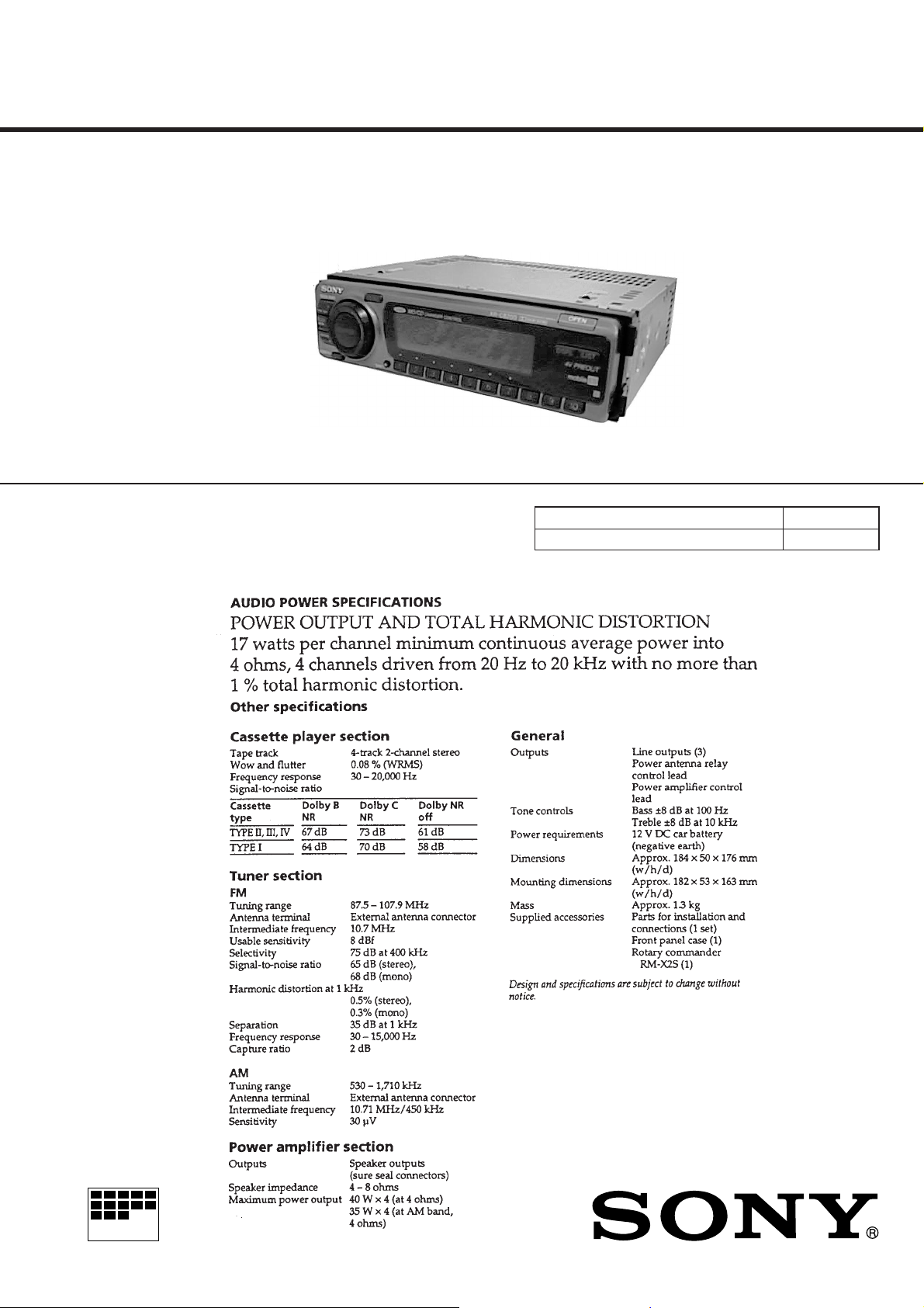
SPECIFICA TIONS
US Model
Model Name Using Similar Mechanism NEW
Tape T ransport Mechanism T ype MG-25D-136
MICROFILM
FM/AM CASSETTE CAR STEREO

TABLE OF CONTENTS
1. GENERAL
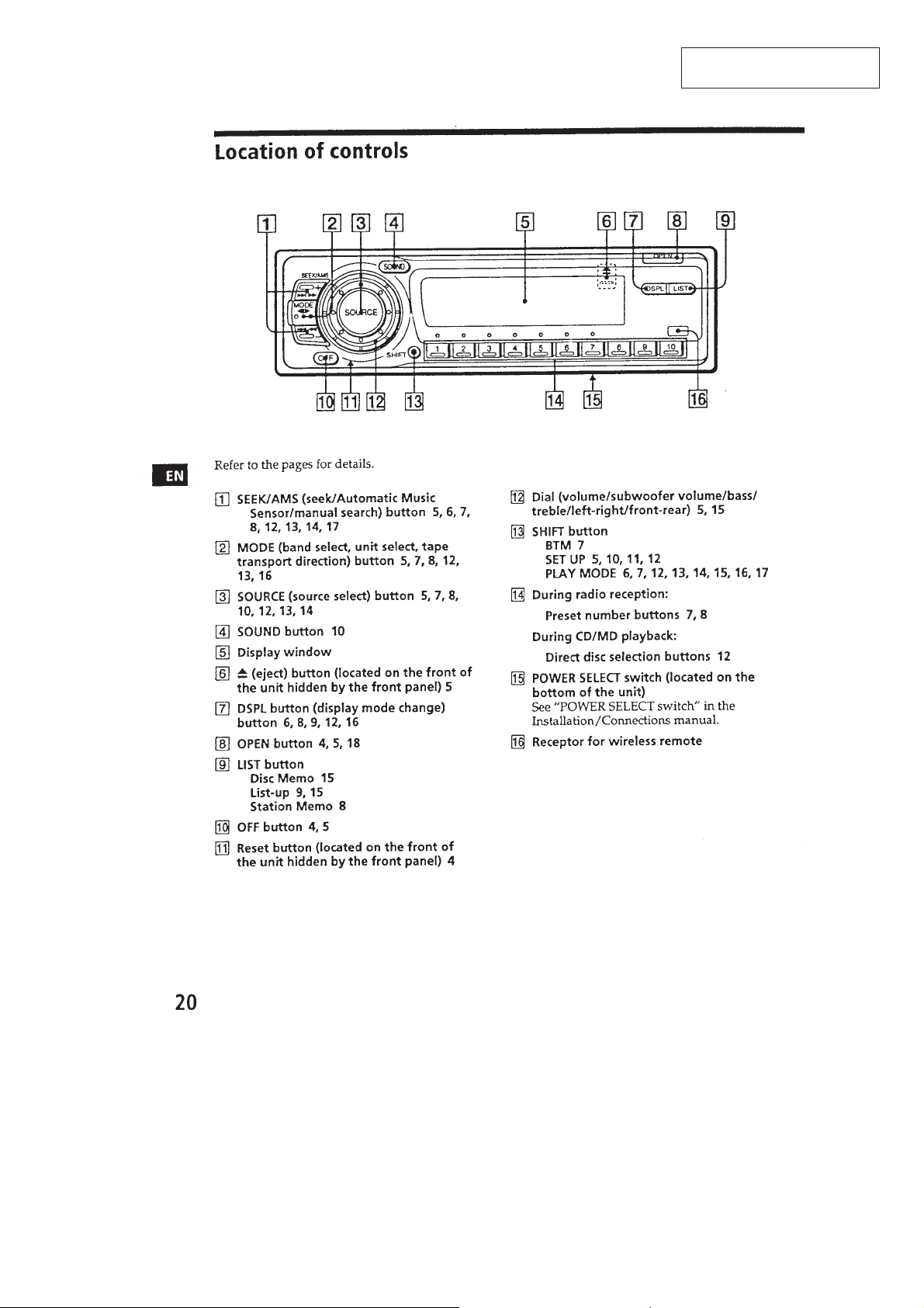
Location of Controls ....................................................... 3
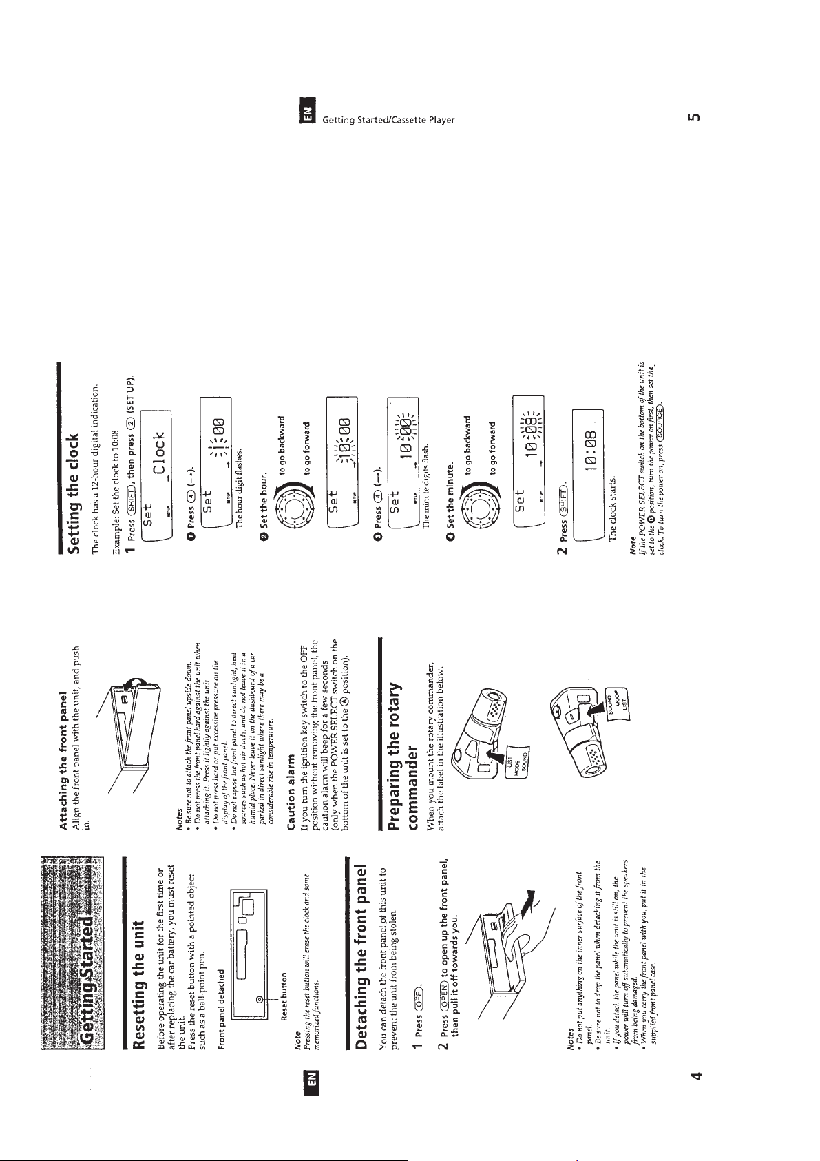
Resetting the Unit ........................................................... 4
Detaching the Font Panel ................................................ 4
Preparing the Rotary Commander .................................. 4
Setting the Clock ............................................................. 4
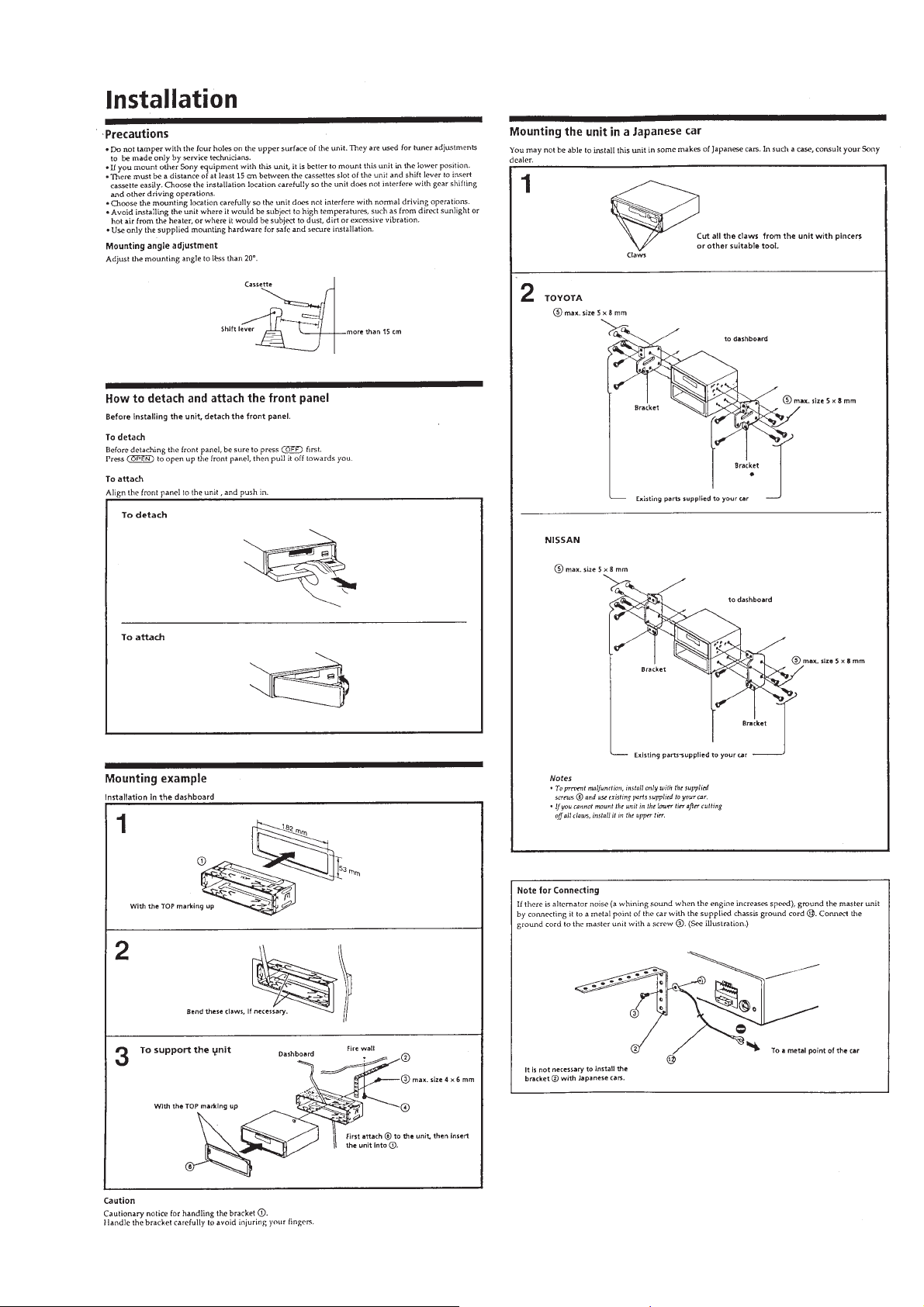
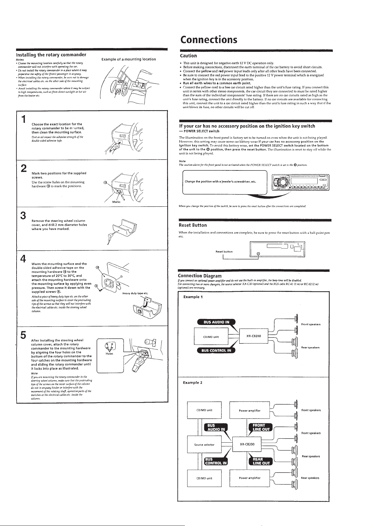
Installation....................................................................... 5
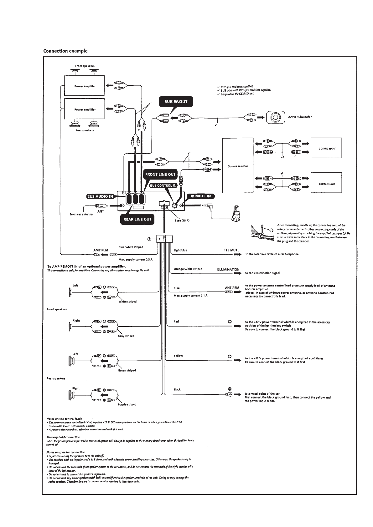
Connections ..................................................................... 6
2. DISASSEMBLY ......................................................... 8
3. ASSEMBLY OF MECHANISM DECK........... 11
4. MECHANICAL ADJUSTMENTS....................... 14
5. ELECTRICAL ADJUSTMENTS
Test Mode........................................................................ 14
Tape Deck Section .......................................................... 14
Tuner Section .................................................................. 15
6. DIAGRAMS
6-1. IC Pin Function Description ........................................... 18
6-2. Printed Wiring Board – MAIN Section –...................... 25
6-3. Schematic Diagram – MAIN Section –.......................... 29
6-4. Printed Wiring Boards – PANEL Section – .................. 33
6-5. Schematic Diagram – PANEL Section –....................... 35
Flexible Circuit Board Repairing
• Keep the temperature of the soldering iron around 270 ˚C during repairing.
• Do not touch the soldering iron on the same conductor of the
circuit board (within 3 times).
• Be careful not to apply force on the conductor when soldering
or unsoldering.
Notes on chip component replacement
• Never reuse a disconnected chip component.
• Notice that the minus side of a tantalum capacitor may be damaged by heat.
7. EXPLODED VIEWS ................................................ 41
8. ELECTRICAL PARTS LIST ............................... 44
– 2 –
SECTION 1
GENERAL
This section is extracted from
instruction manual.
– 3 –
– 4 –
– 5 –
– 6 –
– 7 –
SECTION 2
DISASSEMBLY
Note: Follow the disassembly procedure in the numerical order given.
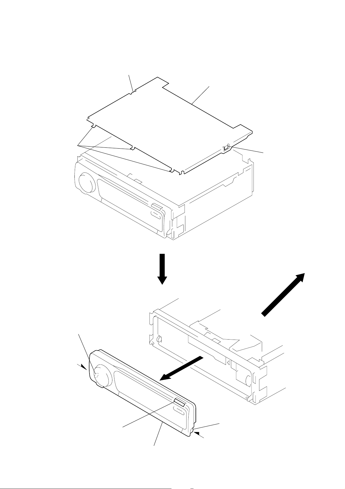
COVER ASS’Y
1
claw
2
three claws
3
cover ass’y
1
claw
FRONT PANEL ASS’Y
3
Push the bearing (L).
1
Push the button (OPEN).
4
front panel ass’y
2
Push the bearing (R).
– 8 –
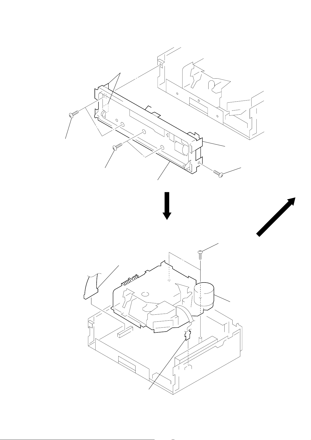
SUB PANEL ASS’Y
)
(
)
k
3
two screws
(PTT2.6
4
two claws
×
8)
2
two screws
(PTT2.6
×
8)
6
sub panel ass’y
5
claw
1
screw
(PTT2.6
×
8
MECHANISM DECK (MG-25D-136)
2
connector
(CN201)
1
two screws
×
6)
(2.6
4
mechanism dec
(MG-25D-136)
3
flexible flat cable
CN231
– 9 –
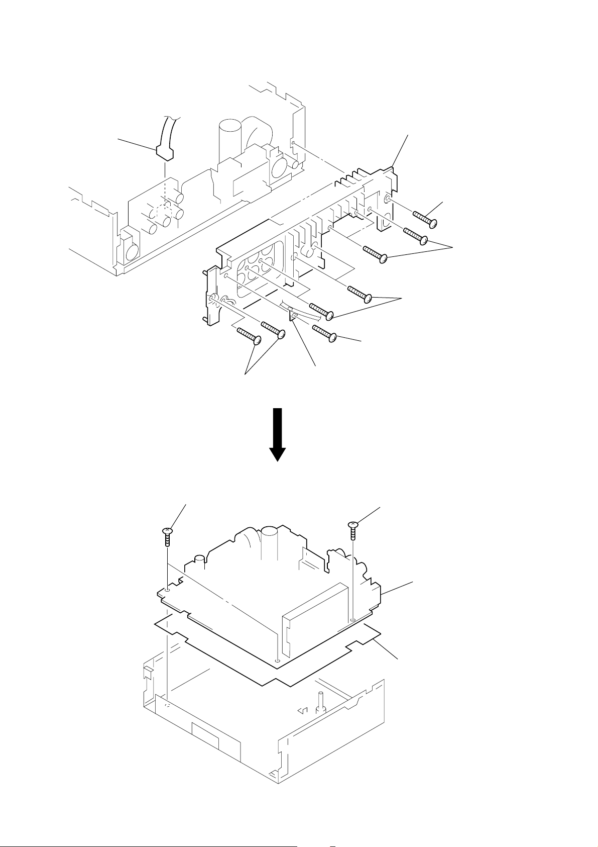
HEAT SINK
d
s
1
connector
(CN302)
2
screw
(PTT2.6 × 8)
8
heat sink
4
four screws
(PTT2.6 × 8)
7
screw
(PTT2.6 × 8)
5
three screw
(PTT2.6 × 8)
MAIN BOARD
6
two screws
(PTT2.6 × 8)
2
two ground point screws
3
cord (with connector)
(SUB w. out)
1
ground point screw
3
main boar
4
insulator
– 10 –
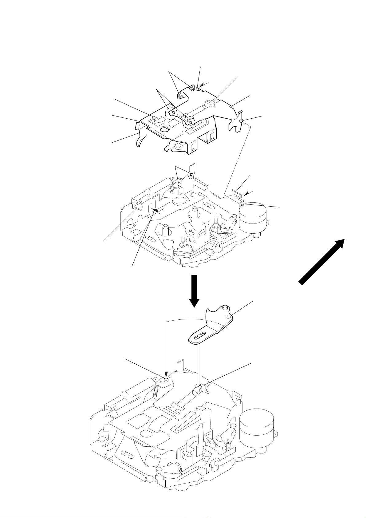
ASSEMBLY OF MECHANISM DECK
2
Move the arm (suction) in the arrow
direction and fit on projection.
1
Fit the arm (suction) on the shaft.
projection
Note: Follow the assembly procedure in the numerical order given.
SECTION 3
HOUSING
4
Fit claw on B part.
3
Put the housing
under A part.
housing
5
Fit projection on C part.
2
Install the hanger onto
two claws of the housing.
C
part
7
Holder the hanger by bending the claw.
1
Install the catch to the hanger.
hanger
6
Fit projection on D part.
8
Hold the hanger by
bending the claw.
D
part
ARM (SUCTION)
A
part
B
part
– 11 –
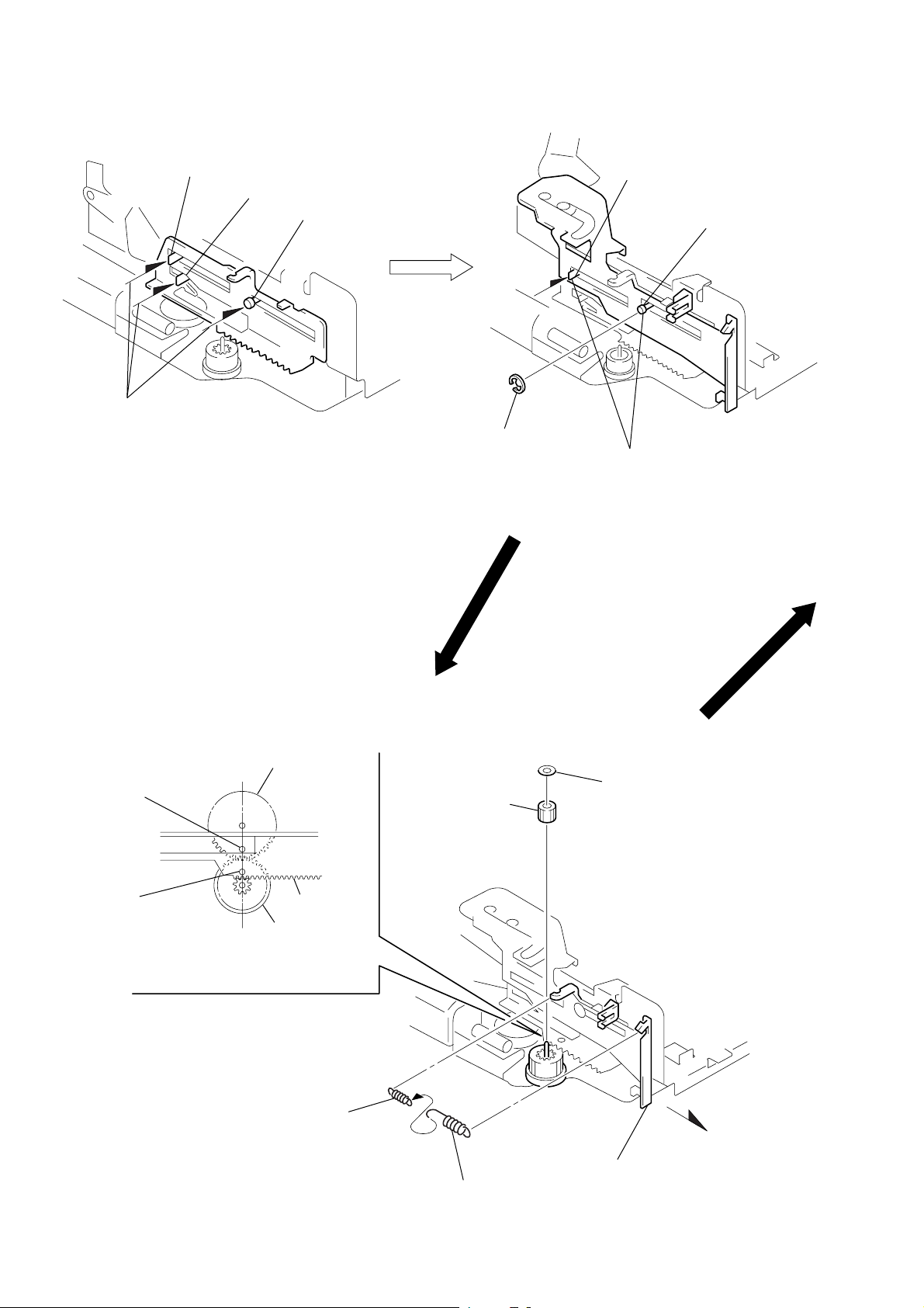
LEVER (LDG-A) / (LDG-B)
shaft
A
1
Fit the lever (LDG-A) on
shafts A – C and install it.
shaft
B
shaft
C
3
type-E stop ring 2.0
shaft
A
Fit the lever (LDG-B) on
2
shafts
install it.
A
and B and
shaft
B
GEAR (LDG-FT)
hole
hole
gear (LDG-D)
lever (LDG-A)
gear (LDG-FB)
4
Align hole in the gear (LDG-D)
with hole the lever (LDG-A).
2
tension spring (LD-2)
5
gear (LDG-FT)
1
6
polyethylene washer
2
tension spring (LD-1)
– 12 –
3
Move the lever (LDG-B)
in the arrow direction.
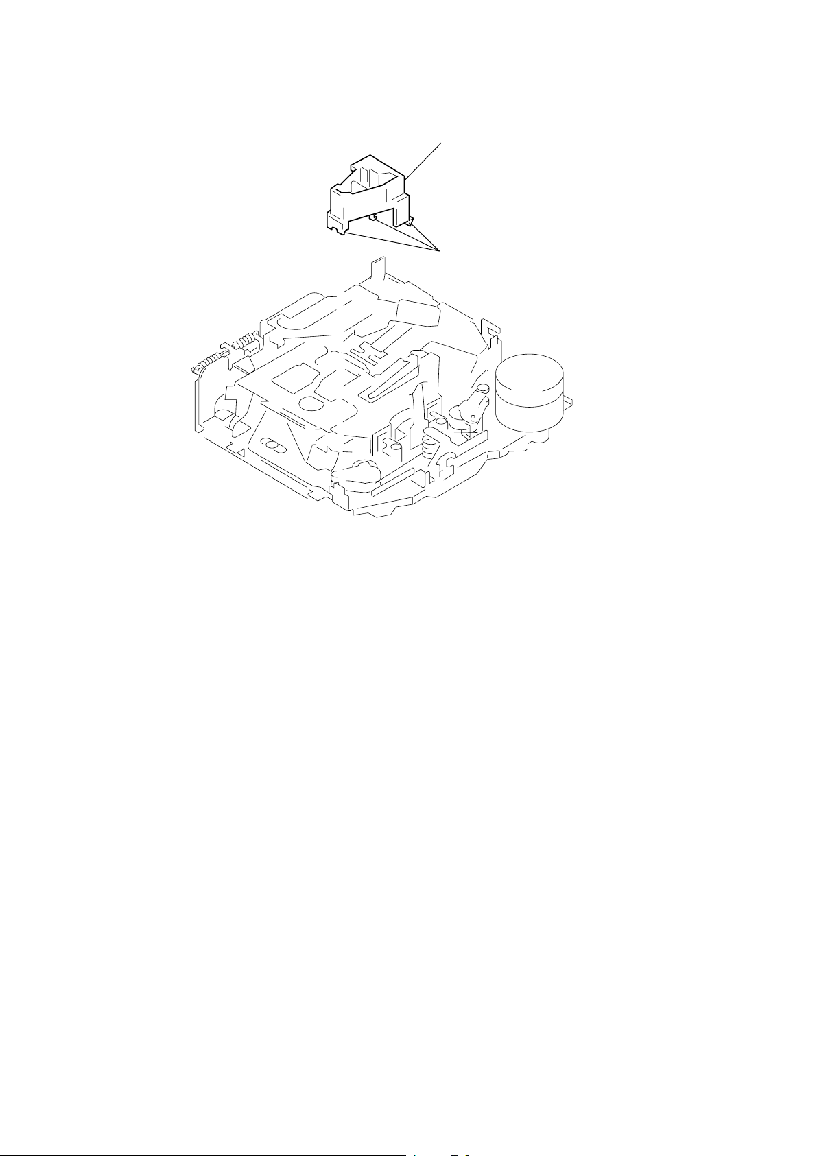
GUIDE (C)
2
guide (C)
1
three claws
– 13 –
 Loading...