

Sony XM-5ES Users guide [fr, es]
5-038-864-11(1)
5-Channel Power
Amplifier
Operating Instructions
Mode d’emploi
Bedienungsanleitung
Manual de instrucciones
Gebruiksaanwijzing
Bruksanvisning
GB
FR
DE
ES
NL
SE
Owner’s Record
The model and serial numbers are located on the bottom of the unit.
Record the serial number in the space provided below.
Refer to these numbers whenever you call upon your Sony dealer
regard
ing this product.
Model No. XM-5ES
Serial No.
XM-5ES

For your safety, be sure to install this unit inside
the trunk (boot) or under the seat.
For details, see “Installation and Connection”
(page 8).
Made in Thailand
The nameplate indicating operating voltage, etc., is
located on the bottom of the chassis.
The validity of the CE marking is restricted to only
those countries where it is legally enforced, mainly
in the countries EEA (European Economic Area) and
Switzerland. The validity of the UKCA marking is
restricted to only those countries where it is legally
enforced, mainly in the UK.
Notice for customers: the following
information is only applicable to equipment
sold in countries applying EU directives
This product has been manufactured by or on
behalf of Sony Corporation.
EU Importer: Sony Europe B.V.
Inquiries to the EU Importer or related to product
compliance in Europe should be sent to the
manufacturer’s authorized representative, Sony
Belgium, bijkantoor van Sony Europe B.V., Da
Vincilaan 7-D1, 1930 Zaventem, Belgium.
Disposal of waste batteries and
electrical and electronic equipment
(applicable in the European Union
and other countries with separate
collection systems)
This symbol on the product, the battery or on the
packaging indicates that the product and the
battery shall not be treated as household waste.
On certain batteries this symbol might be used in
combination with a chemical symbol. The chemical
symbol for lead (Pb) is added if the battery contains
more than 0.004% lead.
By ensuring that these products and batteries are
disposed of correctly, you will help to prevent
potentially negative consequences for the
environment and human health which could be
caused by inappropriate waste handling. The
recycling of the materials will help to conserve
natural resources.
In case of products that for safety, performance or
data integrity reasons require a permanent
connection with an incorporated battery, this
battery should be replaced by qualified service staff
only.
To ensure that the battery and the electrical and
electronic equipment will be treated properly, hand
over these products at end-of-life to the
appropriate collection point for the recycling of
electrical and electronic equipment.
For all other batteries, please view the section on
how to remove the battery from the product safely.
Hand the battery over to the appropriate collection
point for the recycling of waste batteries.
For more detailed information about recycling of
this product or battery, please contact your local
Civic Office, your household waste disposal service
or the shop where you purchased the product or
battery.
If you have any questions or problems concerning
your unit that are not covered in this manual,
consult your nearest Sony dealer.
2GB

Features
•Rated power output of 100 W (at 4 Ω) and 165 W
(at 2 Ω).
•Class D Technology*
•Dynamic Distortion Suppressor*
•Active Thermal Control*
•For car audio units without a line output, direct
connection (High Level Input Connection) to the
speaker output of your car audio unit can be made
using a speaker-wire-to-RCA adaptor (not
supplied).
•High-level sensing turn-on feature allows this unit
to be activated without the need of a REMOTE
connection.
•Built-in HP (high-pass), LP (low-pass) and BP
(band-pass) filter for front and rear channel.
•Built-in variable LPF (low-pass filter) and variable
subsonic filter circuit for subwoofer channel.
•Protection circuit and indicator provided.
•Two subwoofer terminals for parallel subwoofer
connections.
•Pulse power supply*
output power.
*1 Class D Technology
The Class D Technology is a method to convert and
amplify music signals with MOSFETs to high-speed pulse
signals. Furthermore, it features high efficiency and low
heat generation.
*2 Dynamic Distortion Suppressor
The Dynamic Distortion Suppressor suppresses distortion
that occurs at higher playback levels for clear bass
reproduction.
*3 Active Thermal Control
The Active Thermal Control regulates unit operating
temperature for stable, long-term playback at high
volume.
*4 Pulse power supply
This unit has a built-in power regulator which converts
the power supplied by the 12 V DC car battery into highspeed pulses using a semiconductor switch. These
pulses are stepped up by the built-in pulse transformer
and separated into both positive and negative power
supplies before being converted into direct current
again. This is to regulate fluctuating voltage from the car
battery. This lightweight power supply system provides a
highly efficient power supply with a low impedance
output.
1
4
for stable and regulated
2
3
3GB

Table of Contents
Features . . . . . . . . . . . . . . . . . . . . . . . . . . . . . . . . . . . 3
Guide to Parts and Controls
Power Amplifier. . . . . . . . . . . . . . . . . . . . . . . . . . . . . 5
Bass Remote . . . . . . . . . . . . . . . . . . . . . . . . . . . . . . . 7
Installation and Connection
Parts for Installation and Connection . . . . . . . . . . . 8
Installation . . . . . . . . . . . . . . . . . . . . . . . . . . . . . . . . . 8
Connection. . . . . . . . . . . . . . . . . . . . . . . . . . . . . . . . 10
Additional Information
Precautions . . . . . . . . . . . . . . . . . . . . . . . . . . . . . . . 16
Maintenance . . . . . . . . . . . . . . . . . . . . . . . . . . . . . . 16
Specifications . . . . . . . . . . . . . . . . . . . . . . . . . . . . . 17
Troubleshooting . . . . . . . . . . . . . . . . . . . . . . . . . . . 18
Support Site . . . . . . . . . . . . . . . . . . . . . . . . . . . . . . . 18
4GB

Guide to Parts and Controls
TURN-ON
REMOTE SIGNAL
INPUT MODE
1-4
1
CH 1-4
1
-2
1
+3/2+4
BRIDGED
CH 1 CH 2
5
5+6
SUB CH
1
+2
3+4
LINE OUT MODE
THRU ALL
STEREO
CH 3/4
SUB CH
BRIDGED
CH 3 CH 4
REMOTE+12 V
GROUND
L R
L R
SUB CH
50500
FILTER RANGE (
Hz)
HPF (
Hz)
OFF BP
HP LP
5005k
500
150
50
1.5k
LPF (
Hz)
500
150
500505k500
5k
1.5k
INPUT SENS
50500
FILTER RANGE (
Hz)
HPF (
Hz)
OFF BP
HP LP
5005k
500
150
50
1.5k
LPF (
Hz)
500
150
500505k500
5k
1.5k
INPUT SENS
CH 1/2
INPUT SENS
OFF ON
150
50050
OFF ON
30
SUBSONIC FILTER (
Hz)
505
LPF (Hz)
TURN-ON
REMOTE SIGNAL
50500
INPUT MODE
1-4
1
CH 1-4
1
-2
1
+3/2+4
FILTER RANGE (
Hz)
BRIDGED
HPF (
Hz)
OFF BP
HP LP
CH 1 CH 2
5
5+6
SUB CH
1
+2
3+4
LINE OUT MODE
THRU ALL
STEREO
500-
5k
500
150
50
1.5k
LPF (
Hz)
500
150
500505k500
5k
1.5k
INPUT SENS
CH 3/4 SUB CH
BRIDGED
CH 3 CH 4
REMOTE+12 V
GROUND
L R
L R
SUB CH
50500
FILTER RANGE (
Hz)
HPF (
Hz)
OFF BP
HP LP
500-
5k
500
150
50
1.5k
LPF (
Hz)
500
150
500505k500
5k
1.5k
INPUT SENS
CH 1/2
INPUT SENS
OFF ON
150
LPF (
Hz)
50050
OFF ON
30
SUBSONIC FILTER (
Hz)
505
ȫ
ȩ
Ȫ
Ȭ
ȵ ȷȶȭȮȯ ȹȸ
Ȱ
ȱȳ
Ȳȴ
Ȱ
ȱȳ
Ȳȴ
ȺȻ
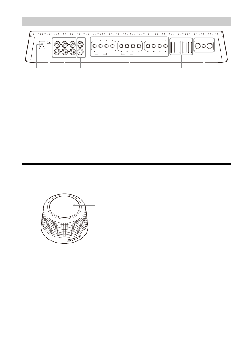
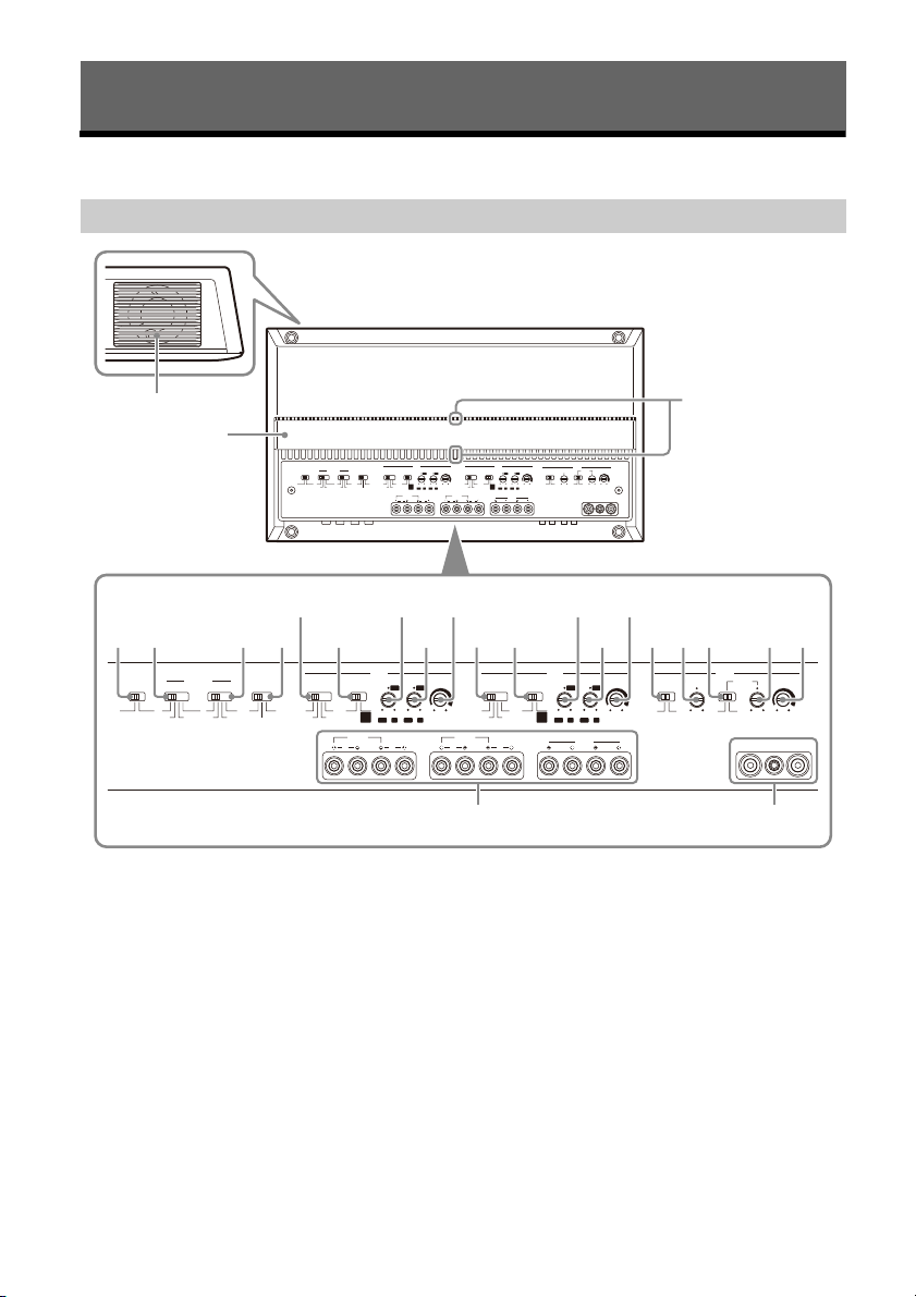
Power Amplifier
Control Panel (Top Panel)
Ventilation outlet
Dissipates heat.
Depending on the temperature of the amplifier,
the fan operates in one of the three statuses:
stopped, low-speed, high-speed.
Heat sink cover
The direction of the heat sink cover can be
changed according to your preference (page 9).
Status indicator light
Lights up in white during operation.
If the protection circuit activates, the status
indicator light changes from white to red. For
details, see “Troubleshooting” (page 18).
TURN-ON switch
Selects the turn-on mode of the amplifier.
• “REMOTE”: Select this for remote turn-on
mode. The amplifier turns on when a turn-on
signal is received from the REMOTE terminal.
See “REMOTE terminal” (page 11) for details.
• “SIGNAL”: Select this for high-level sensing
turn-on mode. The amplifier turns on when a
turn-on signal is received from the INPUT
connector. This feature is only available for
high-level (speaker level) input connection.
See “REMOTE terminal” (page 11) for details.
5GB

INPUT MODE section:
INPUT 1 CH 1
INPUT 2 CH 2
INPUT 3 CH 3
INPUT 4 CH 4
INPUT 1 CH 1
CH 2
CH 3
CH 4
INPUT 1 CH 1
CH 3
INPUT 2 CH 2
CH 4
INPUT 1 CH 1
INPUT 3 CH 3
INPUT 2 CH 2
INPUT 4 CH 4
INPUT 5 SUB CH
INPUT 5 SUB CH
INPUT 6
INPUT 1 SUB CH
INPUT 2
INPUT 3 SUB CH
INPUT 4
CH 1-4 switch
Selects the input mode for CH 1, CH 2, CH 3 and
CH 4.
• “1-4”: For 4-channel stereo input.
• “1”: For 1-channel input.
• “1-2”: For 2-channel input.
• “1+3/2+4”: For 4-channel input.
SUB CH switch
Selects the input mode for SUB CH (subwoofer
channel).
• “5”: For mono subwoofer input.
• “5+6”: For stereo subwoofer input.
• “1+2”: Uses signal input from INPUT 1+2.
• “3+4”: Uses signal input from INPUT 3+4.
LINE OUT MODE switch
Sets the mode of signal output to LINE OUT 1
and 2 connectors. Signal output from all LINE
OUT connectors are unfiltered and not affected
by any FILTER settings.
• “THRU”: Stereo output (through mode)
INPUT 1 LINE OUT 1
INPUT 2 LINE OUT 2
• “STEREO”: Stereo output (summing mode)
INPUT 1 LINE OUT 1
INPUT 3
INPUT 2 LINE OUT 2
INPUT 4
• “ALL”: Mono output (summing mode)
INPUT 1
INPUT 2 LINE OUT 1
INPUT 3 LINE OUT 2
INPUT 4
CH 1/2 and CH 3/4 section:
FILTER switch
Sets the filter mode for CH 1/2 and CH 3/4.
• “OFF”: Turns the filter off.
• “HP” (high-pass): Frequencies lower than HPF
control setting are filtered.
• “LP” (low-pass): Frequencies higher than LPF
control setting are filtered.
• “BP” (band-pass): The range of frequency for
the HPF control is automatically fixed at 50 Hz
– 500 Hz; the range of frequency for LPF
control is automatically fixed at 500 Hz – 5
kHz. Frequencies outside the range of HPF
and LPF settings are filtered.
RANGE switch
Sets the range of frequency for HPF (high-pass
filter) and LPF (low-pass filter) control.
• “50-500”: Range of frequency for subwoofer.
• “500-5k”: Range of frequency for midrange
speaker or tweeter.
HPF (high-pass filter) control
Depending on the RANGE setting, adjusts the
cutoff frequency in the range of 50 Hz – 500 Hz
or 500 Hz – 5 kHz.
LPF (low-pass filter) control
Depending on the RANGE setting, adjusts the
cutoff frequency in the range of 50 Hz – 500 Hz
or 500 Hz – 5 kHz.
INPUT SENS (input sensitivity) control
Adjusts the input level sensitivity for CH 1/2 and
CH 3/4.
Turn the knob clockwise when the output level
of the connected audio devices is low.
SUB CH section:
SUBSONIC FILTER switch
Turns the subsonic filter on or off.
SUBSONIC FILTER control
Adjusts the cutoff frequency (5 Hz – 50 Hz) of the
subsonic filter.
LPF (low-pass filter) switch
Turns the low-pass filter on or off.
LPF (low-pass filter) control
Adjusts the cutoff frequency (50 Hz – 500 Hz) of
the low-pass filter.
INPUT SENS (input sensitivity) control
Adjusts the input level sensitivity for SUB CH.
Turn the knob clockwise when the output level
of the connected audio devices is low.
SPEAKER OUT terminal screw head
+12 V terminal screw head
REMOTE terminal screw head
GROUND terminal screw head
6GB
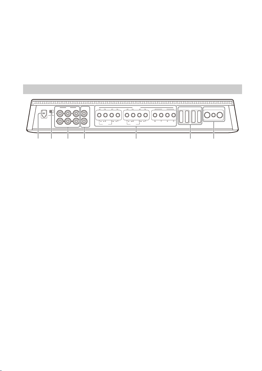
Connector Panel (Front Panel)
13
L
REMOTE+12 V
GROUND
40 A 40 A40 A 40 A
INPUT
VOLTAGE
LOW HIGH
INPUT
SPEAKER OUT
LINE OUT
CH 3
CH 4
1
24 2
R
L
R
5
6
BRIDGED
R
SUB CHCH 1 CH 2
BRIDGED
L R L
BASS
REMOTE
ȼȽ ɀȿɂɁȾ
BASS REMOTE connector
Connector for the bass remote.
INPUT VOLTAGE switch
Selects the type of input connection.
• “LOW”: Select this for low-level (line level)
input connection using RCA extension cables
(not supplied).
• “HIGH”: Select this for high-level (speaker
level) input connection using a speaker-wireto-RCA adaptor (not supplied).
INPUT connector
LINE OUT connector
For details about the connection, see “Output
Connection” (page 15).
SPEAKER OUT terminal
For details about the connection, see “Speaker
Connection” (page 14).
Fuse (40 A)
+12 V terminal
REMOTE terminal
GROUND terminal
For details about the connection, see “Input
Connection” (page 12).
Bass Remote
Bass remote adjusts the bass level output of the SUB CH (subwoofer channel). To use, connect the bass
remote’s cable to the BASS REMOTE connector on the connector panel (front panel).
Volume control knob
Turn the knob clockwise to increase the volume
Ȏ
(gain).
Turn the knob counterclockwise to decrease the
volume (gain).
CAUTION
Excessive gain input may cause distortion of the sound
produced by the connected subwoofer. Do not increase
the gain level excessively on the bass remote. The sound
produced by the connected subwoofer may also
become distorted if the volume of your car audio unit is
set too high.
7GB
Installation and Connection
Installation
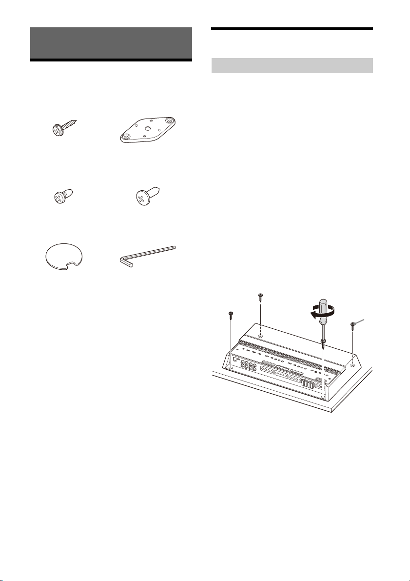
Parts for Installation and
Connection
Mounting screw
Securing s crew
Double-sided tape (1) Hex key (2.5 mm (
This parts list does not include all the package
contents.
(5 × 20 mm (
(2 × 5 mm (
7
/32 × 13/16 in)) (4 )
3
/32 × 7/32 in)) (2)
Mounti ng bracket (1)
Mount ing screw
(3 × 12 mm (1/8 × 1/2 in)) (2)
3
/32 in)) (1)
Installing the Amplifier
•Mount the amplifier either inside the trunk (boot)
or under a seat.
•For your safety, choose a mounting location that
will not interfere with any driving operations.
•Do not install the amplifier near the heater, in
areas that get exposed to direct sunlight or
subject to high temperature.
•Do not install the amplifier under a floor carpet
where the heat dissipation from the amplifier will
be considerably impaired.
•Avoid installing the amplifier in areas subject to
rain, moisture, dust and dirt.
Mounting the amplifier
Place the amplifier on your selected
1
mounting location, then mark the position
of the 4 screw holes on a mounting board
(not supplied).
2 Drill a 3 mm (
and mount the amplifier onto the board
with the mounting screws .
The mounting screws are 20 mm (13/16 in)
long, so make sure that the mounting board is
thicker than 20 mm (
1
/8 in) pilot hole at each mark
13
/16 in).
8GB
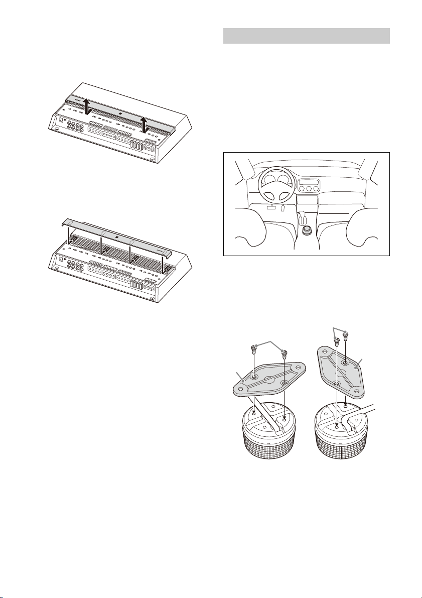
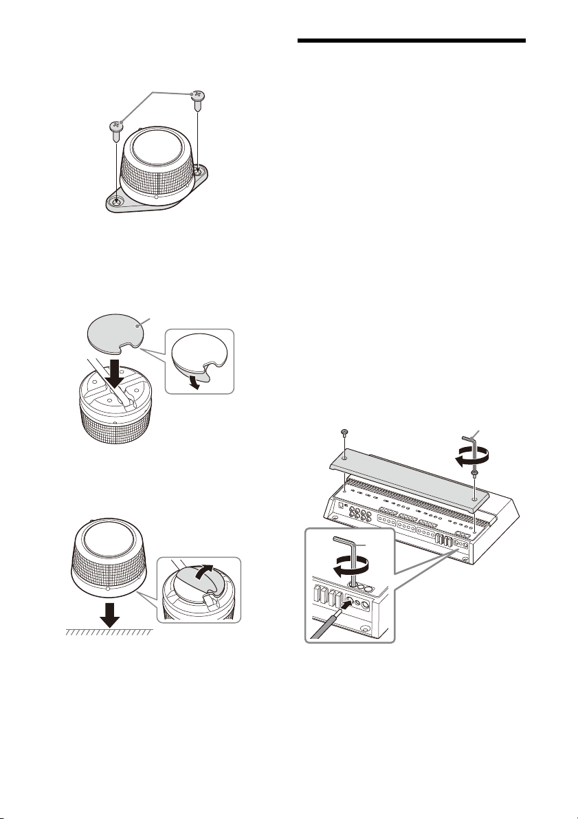
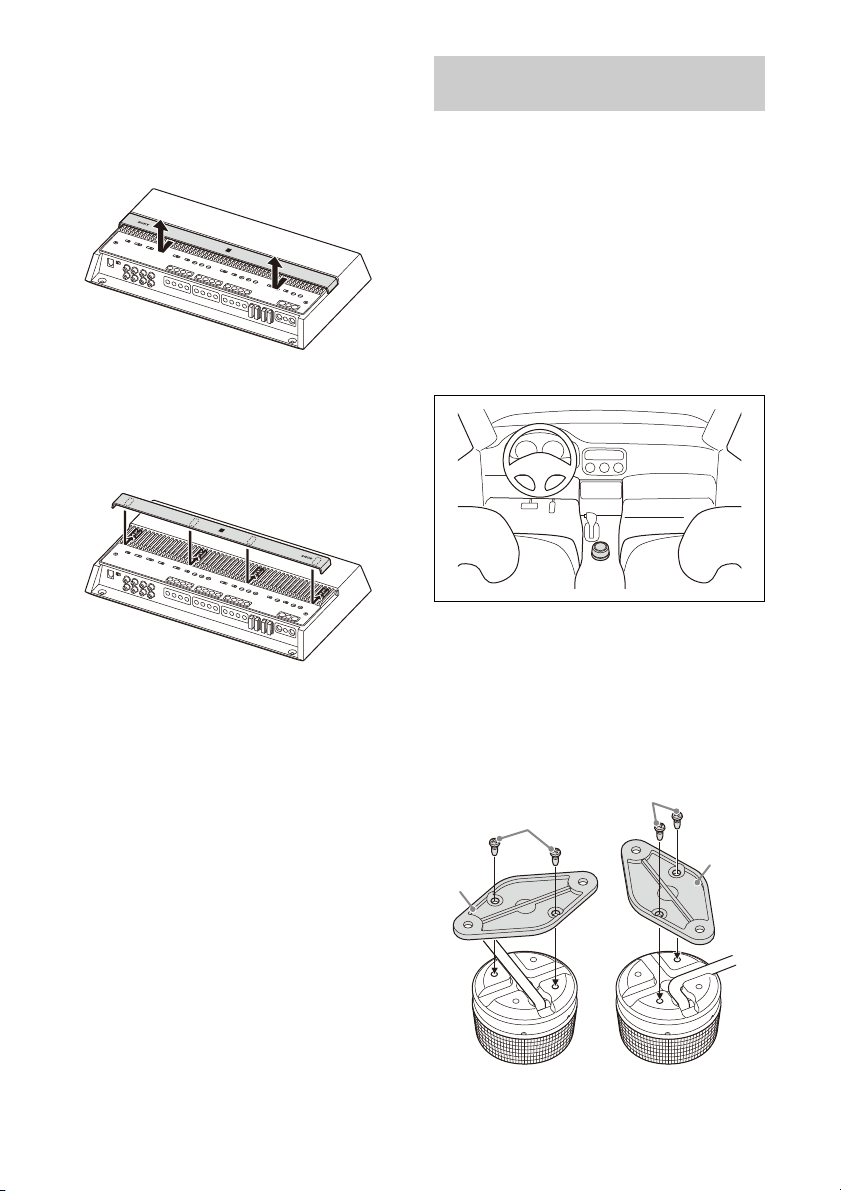
Changing the heat sink cover direction
The direction of the heat sink cover can be changed
according to your preference.
1 Slide the cover forward, then lift to remove
it.
2 Rotate the cover to your desired direction.
3 Align the cover to the catches on the
amplifier, then slide the cover back until it
clicks into place.
Installing the Bass Remote
• Do not install the bass remote near a heater, in
areas that get exposed to direct sunlight or in
areas subject to high temperature.
• Avoid installing the bass remote in areas subject
to dust, dirt or moisture.
• Install the bass remote in a location where:
– There is a flat surface.
– Does not interfere with the driver’s movement.
– Does not hinder the operations of the steering
wheel, shift lever or the brake pedal.
Mounting example
Installing using the mounting bracket
Secure the mounting bracket to the bass
1
remote using the securing screws .
You can secure the mounting bracket
horizontally or vertically to suit your needs.
9GB
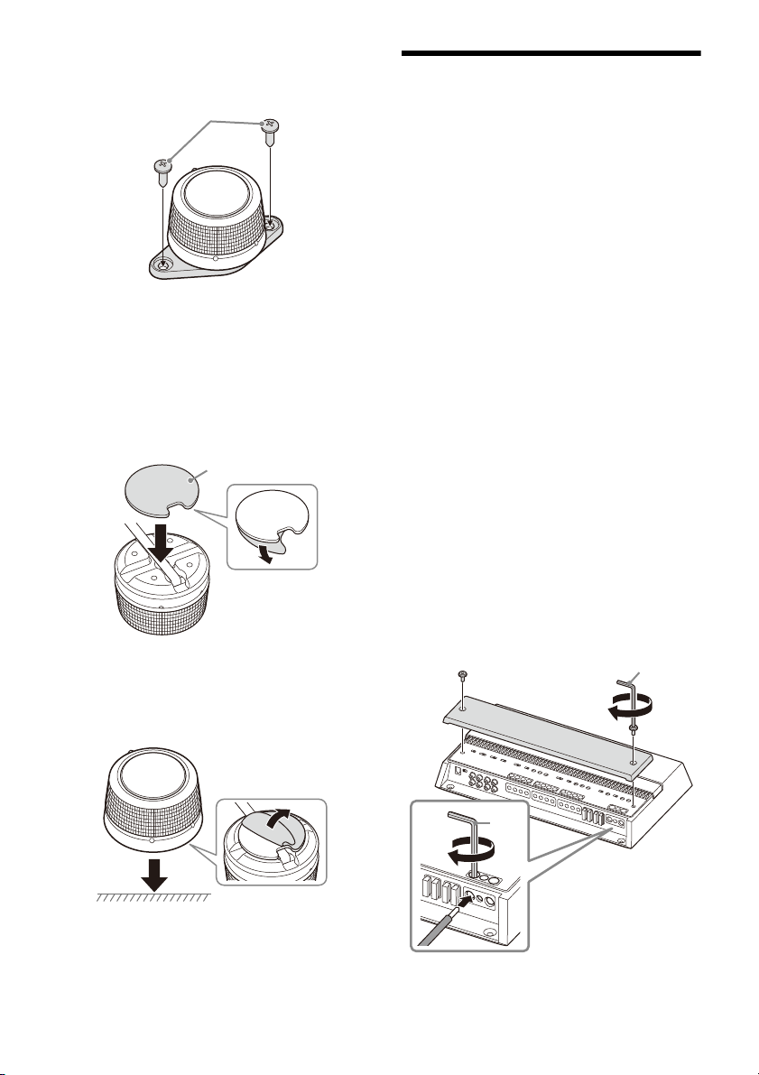
2 Mount the bass remote to your selected
mounting location with the mounting
screws .
Installing using the double-sided tape
Apply the double-sided tape to the base
1
of the bass remote.
Match the curve of the double-sided tape to
that of the bass remote as shown below.
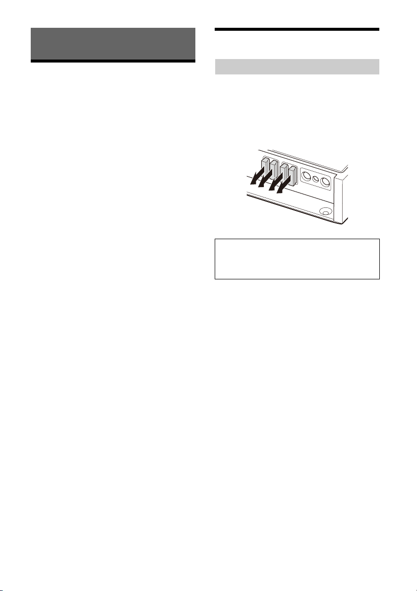
Connection
•Before making any connections, disconnect the
ground (earth) terminal of the car battery to avoid
short circuits. Connect this amplifier to the +12 V
power supply lead only after all other leads have
been connected.
• This amplifier is designed for negative ground
(earth) 12 V DC operation only.
•Do not operate the amplifier on a weak battery as
the amplifier requires a good power supply for
optimum performance.
•If your car is equipped with a computer system for
purposes such as navigation, disconnecting the
ground (earth) terminal of the car battery may
damage the computer memory. Leave the ground
(earth) lead connected and connect this amplifier
to the +12 V power supply lead only after all other
leads have been connected to prevent short
circuits.
•When connecting and installing the input and
output cables, keep them away from the +12 V
power supply lead. Running them close together
may generate interference noise.
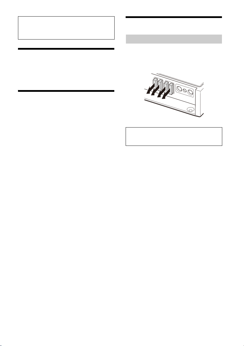
Notes on making connections
•To connect to the terminals on the connector
panel and to adjust various settings, remove the
top cover to access the control panel (top panel).
• When you tighten the screw, be careful not to
apply too much torque as doing so may damage
the terminals or cables.
2 Mount the bass remote to a flat surface.
Clean the surface of your selected mounting
location with a dry cloth before applying the
double-sided tape .
10GB
+
12 V
REMOTE
GROUND
+
12 V
REMOTE
GROUND
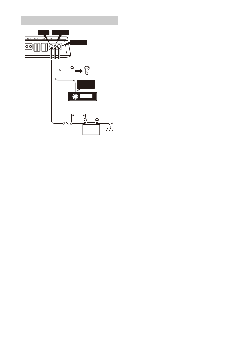
Power Connections
+12 V REMOTE
REMOTE
OUT*
1
GROUND
Fuse (160 A )
to a metal point
on the car chassis
less than 450 mm (1 7 3/4 in)
*1 If you have the factory original or some other car audio
unit without a remote output for the amplifier, connect
the remote input (REMOTE) terminal to the ACC power
supply. In high level input connection, the amplifier can
also be activated without the need of a REMOTE
connection. However, this function is not guaranteed for
all car audio units.
*2 Ground (earth) to the car chassis.
+12 V terminal
•Connect the +12 V power supply lead to the +12 V
terminal only after all the other connections have
been completed.
•Use a +12 V power supply lead with a 160 A fuse
attached.
•During full-power operation, a current of more
than 160 A will run through the system. Therefore,
make sure the leads to be connected to the +12 V
terminal are at least 0-Gauge (AWG-1/0) or have a
sectional area of more than 55 mm² (2
• All power leads connected to the positive battery
post should be fused within 450 mm (17
the battery post before they pass through any
metal.
•Make sure the leads connecting from the car
battery to the metal point on the car chassis are at
least of a lead gauge equal to that of the +12 V
power supply lead connected from the battery to
the amplifier.
•Make sure the leads connecting from the car
battery to the metal point on the car chassis are
not more than 0-Gauge (AWG-1/0) or have a
sectional area of 55 mm² (2
of a lead gauge equal to that of the +12 V power
5
/16 in²), and at least
supply lead connected from the battery to the
amplifier.
5
/16 in²).
3
/4 in) of
GROUND terminal
• Be sure to connect the ground (earth) lead
securely to a metal point on the car chassis. A
loose connection may cause the amplifier to
malfunction.
• During full-power operation, a current of more
than 160 A will run through the system. Therefore,
make sure the leads to be connected to the
GROUND terminal are at least 0-Gauge (AWG-1/0)
or have a sectional area of more than 55 mm²
5
(2
/16 in²).
REMOTE terminal
• To turn on the amplifier using a dedicated remote
turn-on lead, set the TURN-ON switch to
“REMOTE”, then connect the remote output
(REMOTE OUT) of your car audio unit to the
REMOTE terminal.
• When using a car audio unit without a remote
output (REMOTE OUT) for the amplifier, connect
the REMOTE terminal to the ACC power supply of
your car or use the signal sensing turn-on setting
instead.
• Use a remote turn-on lead with a thickness from
AWG-8 to AWG-18 or with sectional area from
8.4 mm² (
Notes on using high-level sensing turn-on
settings
• In high level input connection, the amplifier can
also be activated without the need of a REMOTE
connection. However, this function is not
guaranteed for all car audio units.
• By setting the TURN-ON switch to “SIGNAL”, the
amplifier operates automatically when a turn-on
signal is received from the INPUT connector.
11
/32 in²) to 0.82 mm² (1/16 in²).
11GB
Input Connection
INPUT
VOLTAGE
LOW HIGH
*
INPUT
VOLTAGE
LOW HIGH
*
Speaker output
(left)
Speaker output
(right)
FRONT
AUDIO OUT
REAR
AUDIO OUT
INPUT MODE
1-4
1
CH 1-4
1
-2
1
+3/2+4
**
FRONT
AUDIO
OUT
REAR
AUDIO
OUT
SUB
OUT
INPUT MODE
1-4
1
CH 1-4
1
-2
1
+3/2+4 5
5+6
SUB CH
1
+2
3+4
** *
The INPUT connector can be used by both low-level
input and high-level input.
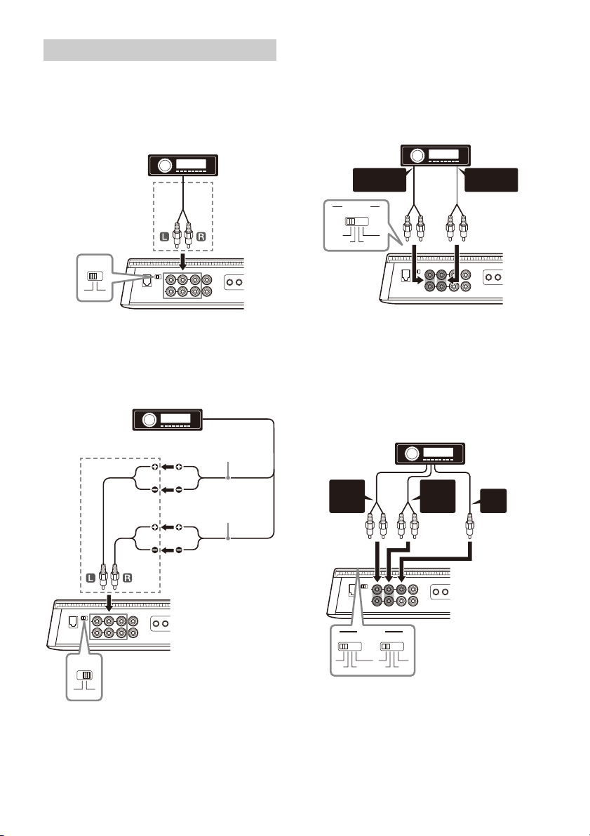
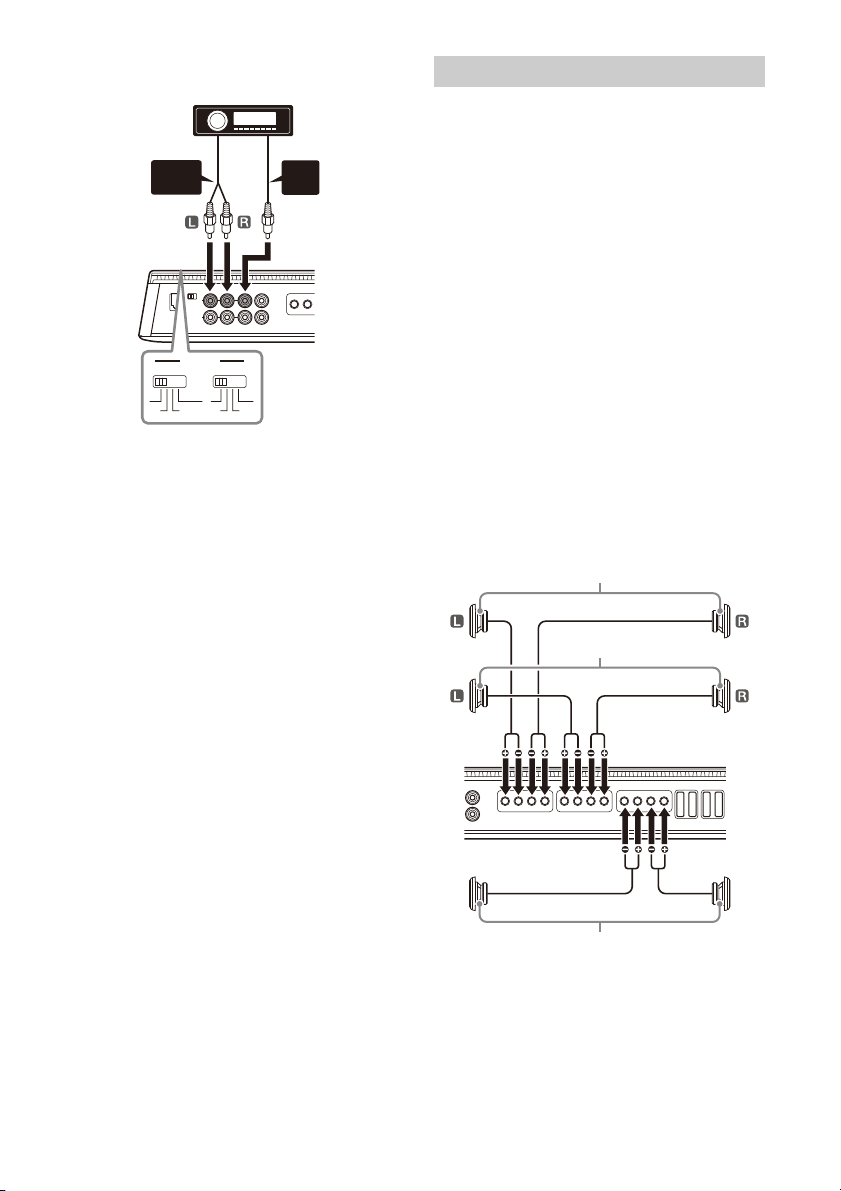
Making low-level input connection
Set the INPUT VOLTAGE switch to “LOW” and
connect the RCA cable (not supplied) from your car
audio to the INPUT connector.
The following shows the connection and settings
typically used when connecting a car audio unit and
this amplifier. Refer to the operating instructions
supplied with your car audio for more details about
the input connection for your car audio unit.
4-channel input
With “Speaker Connection” (page 14) or .
* RCA cable (not supplied)
Making high-level input connection
Set the INPUT VOLTAGE switch to “HIGH” and use a
speaker-wire-to-RCA adaptor (not supplied) to
connect the speaker wire from your car audio to the
INPUT connector.
* Speaker wire-to-RCA adaptor (not supplied)
12GB
* Use a speaker wire-to-RCA adaptor (not supplied) for high-
level input connection.
Note
When making this connection, set the INPUT MODE settings
on the control panel (top panel) to the following positions:
–Set CH 1-4 to “1-4”.
– Set SUB CH to “1+2” o r “3 +4 ” according to your needs.
5-channel input
With “Speaker Connection” (page 14) or .
* Use a speaker wire-to-RCA adaptor (not supplied) for high-
level input connection.
Note
When making this connection, set the INPUT MODE settings
on the control panel (top panel) to the following positions:
–Set CH 1-4 to “1-4”.
–Set SUB CH to “5”.
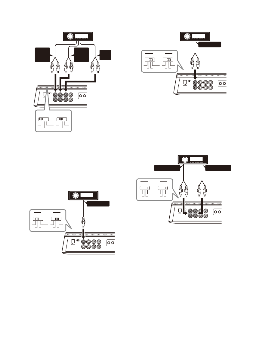
6-channel input
FRONT
AUDIO
OUT
REAR
AUDIO
OUT
SUB
OUT
INPUT MODE
1-4
1
CH 1-4
1
-2
1
+3/2+4 5
5+6
SUB CH
1
+2
3+4
***
AUDIO OUT
INPUT MODE
1-4
1
CH 1-4
1
-2
1
+3/2+4 5
5+6
SUB CH
1
+2
3+4
*
AUDIO OUT
INPUT MODE
1-4
1
CH 1-4
1
-2
1
+3/2+4 5
5+6
SUB CH
1
+2
3+4
*
AUDIO OUT*
1
AUDIO OUT*
2
INPUT MODE
1-4
1
CH 1-4
1
-2
1
+3/2+4 5
5+6
SUB CH
1
+2
3+4
*
3
*
3
With “Speaker Connection” (page 14) or .
* Use a speaker wire-to-RCA adaptor (not supplied) for high-
level input connection.
Note
When making this connection, set the INPUT MODE settings
on the control panel (top panel) to the following positions:
–Set CH 1-4 to “1-4”.
– Set SUB CH to “5+6”.
1-channel input
With “Speaker Connection” (page 14) or .
2-channel input
With “Speaker Connection” (page 14) or .
* Use a speaker wire-to-RCA adaptor (not supplied) for high-
level input connection.
Note
When making this connection, set the INPUT MODE settings
on the control panel (top panel) to the following positions:
– Set CH 1-4 to “1-2”.
– Set SUB CH to “1+2”.
4-channel input
With “Speaker Connection” (page 14) or .
* Use a speaker wire-to-RCA adaptor (not supplied) for high-
level input connection.
Note
When making this connection, set the INPUT MODE settings
on the control panel (top panel) to the following positions:
–Set CH 1-4 to “1”.
– Set SUB CH to “1+2”.
*1 Filtered signal. Tweeter output or HPF output from the
car audio.
*2 Filtered signal. Woofer output or LPF output from the car
audio.
*3 Use a speaker wire-to-RCA adaptor (not supplied) for
high-level input connection.
Note
When making this connection, set the INPUT MODE settings
on the control panel (top panel) to the following positions:
– Set CH 1-4 to “1+3/2+4”.
– Set SUB CH to “3+4”.
13GB
3-channel input
AUDIO
OUT
SUB
OUT
INPUT MODE
1-4
1
CH 1-4
1
-2
1
+3/2+4 5
5+6
SUB CH
1
+2
3+4
**
Front speaker (min. 4 Ω)
Subwoofer (min. 4 Ω)
Rear speaker (min. 4 Ω)
With “Speaker Connection” (page 14) or .
* Use a speaker wire-to-RCA adaptor (not supplied) for high-
level input connection.
Note
When making this connection, set the INPUT MODE settings
on the control panel (top panel) to the following positions:
–Set CH 1-4 to “1-4”.
–Set SUB CH to “5”.
Speaker Connection
•Be sure to use speakers with an adequate power
rating. If you use small capacity speakers, they
may be damaged.
•Do not connect any active speakers (with built-in
amplifiers) to the speaker terminals of the
amplifier. Doing so may damage the active
speakers.
•Use speakers with an appropriate impedance
rating.
– 2 Ω to 8 Ω (stereo)
– 4 Ω to 8 Ω (bridged connection)
• Do not connect the terminal of the speaker
system to the car chassis, and do not connect the
terminal of the right speaker with that of the
left speaker.
Notes
• According to your needs, set the FILTER, RANGE, INPUT
SENS, etc. to the appropriate settings for CH 1/2 and CH 3/
4.
• The following is a depiction of the speaker connections
typically used to connect this amplifier. Refer to the
operating instructions supplied with your car audio and
speakers for more details about the speaker connection
for your car audio unit.
4 speaker + 2 subwoofer system
With “Input Connection” (page 12) , , , ,
or .
14GB

4 speaker + 1 subwoofer system
Front speaker (min. 4 Ω)
Subwoofer (min. 2 Ω)
Rear speaker (min. 4 Ω)
Full range speaker (min. 2 Ω)
Subwoofer (min. 4 Ω)
Full range speaker (min. 2 Ω)
Subwoofer (min. 2 Ω)
Additional amplifier
With “Input Connection” (page 12) , , , ,
or .
2 bridged speaker + 2 subwoofer
system
With “Input Connection” (page 12) .
2 bridged speaker + 1 subwoofer
system
With “Input Connection” (page 12) .
Output Connection
Through the LINE OUT connector, this amplifier can
output signals to additional amplifiers. This allows a
flexible system connection that utilizes multiple
amplifiers.
Notes
• Audio signals output from LINE OUT connectors are not
affected by any signal processing, such as the HPF and LPF
settings.
• According to your needs, set the LINE OUT MODE switch
on the control panel (top panel) to “THRU”, “STEREO” or
“AL L”.
• Refer to the operating instructions supplied with your
additional amplifier for connection details.
15GB
Additional Information
Maintenance
Precautions
•This power amplifier employs a protection circuit*
to protect the transistors and speakers if the
amplifier malfunctions. Do not attempt to test the
protection circuits by covering the heat sink or
connecting improper loads.
•If your car is parked in direct sunlight and there is
a considerable rise in temperature inside the car,
allow the unit to cool down before use.
•For safety, keep the volume of the unit at a
moderate level that allows you to sufficiently hear
the sound of traffic outside the vehicle.
•Do not splash liquid onto the amplifier.
* Protection circuit
This amplifier is provided with a protection circuit
that operates in the following cases:
– When the unit overheats
– When a DC current is generated
– When the speaker terminals are short-circuited
The status indicator light will blink, and this unit
will shut down. If this happens, stop the media
playback, turn off the connected equipment and
determine the cause of the malfunction. If this
unit has overheated, wait until it cools down
before use.
If you have any questions or problems concerning
your unit that are not covered in this Operating
Instruction, consult your nearest Sony dealer.
Fuse Replacement
When replacing the fuse, be sure to use one
matching the amperage rating stated on the
original fuse.
If the fuse blows, check the power connection and
repl
ace the fuse.
If the fuse blows again after replacement, there
may be a
n internal malfunction. If this happens,
consult your nearest Sony dealer.
Warning
Never use a fuse with an amperage rating
exceeding the one supplied with the amplifier as
this could damage the amplifier.
16GB

Specifications
ɻ
ɹ
FOR THE CUSTOMERS IN THE USA.
POUR LES CLIENTS AUX ÉTATS-UNIS.
AUDIO POWER SPECIFICATIONS
Circuit system:
Inputs:
Input level adjustment range:
Outputs:
Speaker impedance:
Maximum output:
Rated output:
Frequency response:
THD (total harmonic distortion):
Low-pass filter:
High-pass filter:
Subsonic filter:
Power requirements:
Power supply voltage:
CTA2006 Standard
Power Output:
100 Watts RMS × 4 Channels at 4 Ohms,
450 Watts RMS × 1 Channel at 4 Ohms
and ≤ 1% THD+N;
165 Watts RMS × 4 Channels at 2 Ohms,
750 Watts RMS × 1 Channel at 2 Ohms
and ≤ 1% THD+N
Signal to Noise Ratio:
77 dBA (reference: 1 Watt into 4 Ohms)
Class D Technology circuit
Pulse power supply
RCA pin jacks
0.2 V – 8 V (RCA pin jacks)
3 V – 16 V (high-level input)
Speaker terminals
RCA pin jacks
2 Ω – 8 Ω (stereo)
4 Ω – 8 Ω (when used as a bridging amplifier)
4 Speakers: 237.5 W × 4 (at 2 Ω) / Total 950 W
1 Woofer/Subwoofer: 950 W (at 2 Ω)
2 Speakers: 330 W × 2 (at 4 Ω)
4 Speakers: 165 W × 4 (at 2 Ω), 100 W × 4 (at 4 Ω)
1 Woofer/Subwoofer: 450 W × 1 (at 4 Ω)
1 Woofer/Subwoofer: 750 W × 1 (at 2 Ω)
CH 1-4: 10 Hz – 40 kHz ( dB)
SUB CH: 10 Hz – 500 Hz ( dB)
0.05% or less (at 1 kHz, 4 Ω)
50 Hz – 500 Hz, 12 dB/oct
500 Hz – 5 kHz, 12 dB/oct
50 Hz – 500 Hz, 12 dB/oct
500 Hz – 5 kHz, 12 dB/oct
5 Hz – 50 Hz, 24 dB/oct
12 V DC car battery (negative ground (earth))
10.5 V – 16 V
Current drain:
At rated output:
30 A (4 Ω, 100 W × 4)
80 A (2 Ω, 750 W × 1)
Remote input: 4 mA
Dimensions:
Approx. 380 mm × 60 mm × 215 mm (15 in ×
3
2
/8 in × 81/2 in) (w/h/d)
ɸɼ
ɺ
380 mm (15 in)
330 mm (13 in)
215 mm (8
196 mm (7
60 mm (2
Mass:
Approx. 4.3 kg (9 lb 8 oz) not incl. accessories
Package contents:
Main unit (1)
Bass remote (1)
Parts for installation and connection (1 set)
Design and specifications are subject to change
without notice.
1
/2 in)
3
/4 in)
3
/8 in)
17GB

Troubleshooting
The following checklist will assist in the correction
of most of the problems you may encounter with
your unit. Please refer to the connection and
operating procedures before going through the
checklist below.
The status indicator light does not light up.
The fuse is blown.
– Replace the fuse with a new one.
The ground (earth) lead is not securely
connected.
– Fasten the ground (earth) lead securely to a
metal point on the car chassis.
The voltage going into the remote input
(REMOTE) terminal is too low.
– Turn on the car audio unit if it is not turned on.
– Use a relay if the system employs too many
amplifiers.
Check the battery voltage (10.5 V – 16 V).
The status indicator light changes from white to
red.
Turn off the amplifier. The speaker outputs have
shorted.
– Rectify the cause of the short.
Turn off the amplifier. Make sure the speaker lead
and ground (earth) lead are securely connected.
The amplifier becomes abnormally hot.
The amplifier heats up abnormally.
– Use speakers with suitable impedance: 2 Ω –
8 Ω (stereo) or 4 Ω – 8 Ω (when used as a
bridging amplifier).
Make sure to place the amplifier in a well
ventilated location.
The sound is interrupted.
The thermal protector has activated.
– Reduce the volume.
Alternator noise is heard.
The power connecting leads are installed too
close to the RCA pin cables.
– Keep the leads away from the cables.
The ground (earth) lead is not securely
connected.
– Fasten the ground (earth) lead securely to a
metal point of the car.
Negative speaker wires are touching the car
chassis.
– Keep the wires away from the car chassis.
The sound is muffled.
The FILTER switch is set to “LP”.
– When connecting the full range speaker, set to
“OFF” or “HP”.
The sound is too quiet.
The INPUT SENS control setting is not
appropriate. Turn the INPUT SENS control in the
clockwise direction.
If these solutions do not help improve the situation,
consult your nearest Sony dealer.
Support Site
If you have any questions for the latest support
information on this product, please visit the
website below:
Customers in the USA/Canada/Latin America:
https://www.sony.com/am/support
Customers in European countries:
https://www.sony.eu/support
Customers in other countries/regions:
https://www.sony-asia.com/support
18GB
為了確保您的安全,請務必將本裝置安裝在行李箱
內或座位下方。
關於詳細說明,請參閱 “Installation and
Connection” (第 8 頁)。
遠端低音
注意
過度的增益輸入可能使連接的重低音揚聲器發出的聲音失
真。請勿在遠端低音上過度提高增益等級。如果汽車音響
裝置的音量設定太高,連接的重低音揚聲器發出的聲音也
可能失真。
使用前注意事項
•本功率放大器採用保護電路 *,在萬一放大器故障時
保護電晶體和揚聲器。請勿嘗試覆蓋散熱器或連接不
當負載以測試保護電路。
•如果愛車停在直接日照下,而且車內溫度大幅上升,
在使用本裝置之前,請讓它冷卻。
•為安全起見,請讓本裝置保持中等音量,以便能充分
聽到車外的交通噪聲。
•切勿將液體濺灑在放大器上。
* 保護電路
本放大器具備在下列狀況會操作的保護電路:
– 本裝置過熱時
– 產生 DC 電流時
– 揚聲器端子短路時
狀態指示燈會閃爍,本裝置會關機。若發生這種狀
況,請停止播放媒體,關閉連接的設備,判斷故障
的原因。若本裝置過熱,在使用前請讓它冷卻。
若您有任何關於本機的問題或困難,而本使用說明書
沒有提及,請向您附近的 Sony 經銷商諮詢。
保養
更換保險絲
更換保險絲時,必須確保所使用的保險絲與原保險絲
的額定安培數相同。
如果保險絲燒斷,請檢查電源連接並更換保險絲。
如果保險絲更換後又被燒斷,則可能是內部故障。如
果發生這個問題,請就近
警告
絕勿使用額定安培數超過放大器隨附保險絲的保險
絲,否則可能會損壞放大器。
與 Sony 經銷商聯絡。

Pour votre sécurité, veillez à installer cet appareil
dans le coffre ou sous un siège.
Pour plus d’informations, reportez-vous à la
section « Installation et raccordements » (page 9).
Fabriqué en Thaïlande
La plaque signalétique reprenant la tension
d’alimentation, etc., se trouve sur le dessous du
châssis.
La validité du libellé CE se limite uniquement aux
pays où la loi l’impose, principalement les pays de
l’EEE (Espace économique européen) et la Suisse.
La validité du libellé UKCA se limite uniquement aux
pays où la loi l’impose, principalement au
Royaume-Uni.
Avis à l’attention des clients : les informations
suivantes s’appliquent uniquement aux
appareils vendus dans des pays qui
appliquent les directives de l’Union
Européenne
Ce produit a été fabriqué par ou pour le compte de
Sony Corporation.
Importateur dans l’UE : Sony Europe B.V.
Les questions basées sur la législation européenne
pour l’importateur ou relatives à la conformité des
produits doivent être adressées au mandataire :
Sony Belgium, bijkantoor van Sony Europe B.V., Da
Vincilaan 7-D1, 1930 Zaventem, Belgique.
Elimination des piles et
accumulateurs et des équipements
électriques et électroniques
usagés (applicable dans les pays
de l’Union Européenne et dans les
autres pays disposant de systèmes
de collecte sélective)
Ce symbole apposé sur le produit, la pile ou
l’accumulateur, ou sur l’emballage, indique que le
produit et les piles et accumulateurs fournis avec ce
produit ne doivent pas être traités comme de
simples déchets ménagers. Sur certains types de
piles, ce symbole apparaît parfois combiné avec un
symbole chimique. Le symbole pour le plomb (Pb)
est rajouté lorsque ces piles contiennent plus de
0,004 % de plomb. En vous assurant que les
produits, piles et accumulateurs sont mis au rebut
de façon appropriée, vous participez activement à
la prévention des conséquences négatives que leur
mauvais traitement pourrait provoquer sur
l’environnement et sur la santé humaine. Le
recyclage des matériaux contribue par ailleurs à la
préservation des ressources naturelles. Pour les
produits qui, pour des raisons de sécurité, de
performance ou d’intégrité des données,
nécessitent une connexion permanente à une pile
ou à un accumulateur intégré(e), il conviendra de
vous rapprocher d’un Service Technique qualifié
pour effectuer son remplacement. En rapportant
votre appareil électrique, les piles et accumulateurs
en fin de vie à un point de collecte approprié vous
vous assurez que le produit, la pile ou
l’accumulateur intégré sera traité correctement.
Pour tous les autres cas de figure et afin d’enlever
les piles ou accumulateurs en toute sécurité de
votre appareil, reportez-vous au manuel
d’utilisation. Rapportez les piles et accumulateurs,
et les équipements électriques et électroniques
usagés au point de collecte approprié pour le
recyclage. Pour toute information complémentaire
au sujet du recyclage de ce produit ou des piles et
accumulateurs, vous pouvez contacter votre
municipalité, votre déchetterie locale ou le point de
vente où vous avez acheté ce produit.
Si vous avez des questions concernant cet appareil
ou si vous rencontrez des problèmes qui ne sont
pas abordés dans ce mode d’emploi, contactez
votre revendeur Sony le plus proche.
2FR

Caractéristiques
•Puissance de sortie nominale de 100 W (à 4 Ω) et
165 W (à 2 Ω).
•Technologie de classe D*
•Suppresseur de distorsion dynamique*
•Contrôle thermique actif*
•Pour les autoradios ne comportant pas une sortie
de ligne, un raccordement direct (raccordement
d’entrée haut niveau) avec la sortie haut-parleur
de votre autoradio est possible en utilisant un
adaptateur fil haut-parleur vers RCA (non fourni).
•Une fonction de mise sous tension par détection
de haut niveau permet à cet appareil d’être activé
sans un raccordement à REMOTE.
•Filtres HP (passe-haut), LP (passe-bas) et BP
(passe bande) intégrés pour les canaux avant et
arrière.
•LPF (filtre passe-bas) variable et filtre subsonique
variable intégrés pour le canal du caisson de
graves.
•Circuit et indicateur de protection fournis.
• Deux bornes de caissons de graves permettent les
raccordements de caissons de graves en parallèle.
• Alimentation électrique par impulsions*
puissance de sortie stable et régulée.
*1 Technologie de classe D
La technologie de classe D est une méthode permettant
de convertir et d’amplifier des signaux musicaux grâce à
des transistors MOSFET pour obtenir des signaux par
impulsion à grande vitesse. De plus, elle est caractérisée
par une efficacité de haut niveau et un faible
dégagement de chaleur.
*2 Suppresseur de distorsion dynamique
Le suppresseur de distorsion dynamique supprime la
distorsion qui se produit avec des niveaux de lecture
supérieurs afin d’obtenir une reproduction claire des
sons graves.
*3 Contrôle thermique actif
Le contrôle thermique actif régule la température de
fonctionnement de l’appareil afin de garantir une lecture
stable sur de longues durées avec un volume élevé.
*4 Alimentation électrique par impulsions
Cet appareil est équipé d’un régulateur de puissance
intégré qui convertit la pui ssance fournie par une ba tterie
de voiture de 12 V CC en impulsions ultrarapides au
moyen d’un commutateur à semi-conducteur. Ces
impulsions sont amplifiées par le transformateur
d’impulsions intégré et séparées en alimentations
positive et négative avant d’être reconverties en courant
continu. Ce processus permet de compenser les
fluctuations de tension provenant de la batterie de
voiture. Ce système d’alimentation léger assure une
alimentation électrique très efficace avec une sortie
d’impédance faible.
1
3
2
4
pour une
3FR

Table des matières
Caractéristiques. . . . . . . . . . . . . . . . . . . . . . . . . . . . . 3
Emplacement des commandes
Amplificateur de puissance . . . . . . . . . . . . . . . . . . . 5
Commande des graves à distance . . . . . . . . . . . . . 8
Installation et raccordements
Pièces destinées à l’installation et aux
raccordements. . . . . . . . . . . . . . . . . . . . . . . . . . . 9
Installation . . . . . . . . . . . . . . . . . . . . . . . . . . . . . . . . . 9
Raccordement . . . . . . . . . . . . . . . . . . . . . . . . . . . . . 11
Informations complémentaires
Précautions . . . . . . . . . . . . . . . . . . . . . . . . . . . . . . . 17
Entretien. . . . . . . . . . . . . . . . . . . . . . . . . . . . . . . . . . 17
Spécifications . . . . . . . . . . . . . . . . . . . . . . . . . . . . . 18
Dépannage . . . . . . . . . . . . . . . . . . . . . . . . . . . . . . . 19
Site d’assistance . . . . . . . . . . . . . . . . . . . . . . . . . . . 19
4FR
Emplacement des commandes
TURN-ON
REMOTE SIGNAL
INPUT MODE
1-4
1
CH 1-4
1
-2
1
+3/2+4
BRIDGED
CH 1 CH 2
5
5+6
SUB CH
1
+2
3+4
LINE OUT MODE
THRU ALL
STEREO
CH 3/4
SUB CH
BRIDGED
CH 3 CH 4
REMOTE+12 V
GROUND
L R
L R
SUB CH
50500
FILTER RANGE (
Hz)
HPF (
Hz)
OFF BP
HP LP
5005k
500
150
50
1.5k
LPF (
Hz)
500
150
500505k500
5k
1.5k
INPUT SENS
50500
FILTER RANGE (
Hz)
HPF (
Hz)
OFF BP
HP LP
500-
5k
500
150
50
1.5k
LPF (
Hz)
500
150
500505k500
5k
1.5k
INPUT SENS
CH 1/2
INPUT SENS
OFF ON
150
50050
OFF ON
30
SUBSONIC FILTER (
Hz)
505
LPF (Hz)
TURN-ON
REMOTE SIGNAL
50500
INPUT MODE
1-4
1
CH 1-4
1
-2
1
+3/2+4
FILTER RANGE (
Hz)
BRIDGED
HPF (
Hz)
OFF BP
HP LP
CH 1 CH 2
5
5+6
SUB CH
1
+2
3+4
LINE OUT MODE
THRU ALL
STEREO
500-
5k
500
150
50
1.5k
LPF (
Hz)
500
150
500505k500
5k
1.5k
INPUT SENS
CH 3/4 SUB CH
BRIDGED
CH 3 CH 4
REMOTE+12 V
GROUND
L R
L R
SUB CH
50500
FILTER RANGE (
Hz)
HPF (
Hz)
OFF BP
HP LP
500-
5k
500
150
50
1.5k
LPF (
Hz)
500
150
500505k500
5k
1.5k
INPUT SENS
CH 1/2
INPUT SENS
OFF ON
150
LPF (
Hz)
50050
OFF ON
30
SUBSONIC FILTER (
Hz)
505
ȫ
ȩ
Ȫ
Ȭ
ȵ ȷȶȭȮȯ ȹȸ
Ȱ
ȱȳ
Ȳȴ
Ȱ
ȱȳ
Ȳȴ
ȺȻ
Amplificateur de puissance
Panneau de commande (panneau supérieur)
Sortie de ventilation
Permet à la chaleur de se dissiper.
Selon la température de l’amplificateur, le
ventilateur fonctionne dans l’un des trois états
(arrêté, vitesse lente, vitesse rapide).
Capot du dissipateur thermique
L’orientation du capot du dissipateur thermique
peut être modifiée selon votre préférence
(page 10).
Indicateur d’état lumineux
S’allume en blanc en cours de fonctionnement.
Lorsque le circuit de protection s’active,
l’indicateur d’état lumineux passe du blanc au
rouge. Pour plus d’informations, reportez-vous à
la section « Dépannage » (page 19).
Commutateur TURN-ON
Permet de sélectionner le mode de mise sous
tension de l’amplificateur.
• « REMOTE » : sélectionnez cette option pour
activer le mode de mise sous tension à
distance. L’amplificateur est mis sous tension
lorsqu’un signal de mise sous tension est reçu
de la borne REMOTE. Reportez-vous à la
sect ion « Borne REMOT E » (p age 12) po ur p lus
d’informations.
• « SIGNAL » : sélectionnez cette option pour
activer le mode de mise sous tension par
détection de haut niveau. L’amplificateur est
mis sous tension lorsqu’un signal de mise
sous tension est reçu du connecteur INPUT.
Cette fonctionnalité est uniquement
disponible pour un raccordement des entrées
5FR

(niveau des haut-parleurs) haut niveau.
INPUT 1 CH 1
INPUT 2 CH 2
INPUT 3 CH 3
INPUT 4 CH 4
INPUT 1 CH 1
CH 2
CH 3
CH 4
INPUT 1 CH 1
CH 3
INPUT 2 CH 2
CH 4
INPUT 1 CH 1
INPUT 3 CH 3
INPUT 2 CH 2
INPUT 4 CH 4
INPUT 5 SUB CH
INPUT 5 SUB CH
INPUT 6
INPUT 1 SUB CH
INPUT 2
INPUT 3 SUB CH
INPUT 4
INPUT 1 LINE OUT 1
INPUT 3
INPUT 2 LINE OUT 2
INPUT 4
INPUT 1
INPUT 2 LINE OUT 1
INPUT 3 LINE OUT 2
INPUT 4
Reportez-vous à la section « Borne REMOTE »
(page 12) pour plus d’informations.
INPUT MODE :
Commutateur CH 1-4
Permet de sélectionner le mode d’entrée pour
CH 1, CH 2, CH 3 et CH 4.
• « 1-4 » : pour une entrée stéréo à 4 canaux.
• « 1 » : pour une entrée stéréo à 1 canal.
• « 1-2 » : pour une entrée stéréo à 2 canaux.
• « 1+3/2+4 » : pour une entrée à 4 canaux.
Commutateur SUB CH
Permet de sélectionner le mode d’entrée pour
SUB CH (canal du caisson de graves).
• « 5 » : pour une entrée de caisson de graves
mono.
• « 5+6 » : pour une entrée de caisson de
graves stéréo.
• « 1+2 » : permet d’utiliser l’entrée de signal
provenant de INPUT 1+2.
• « 3+4 » : permet d’utiliser l’entrée de signal
provenant de INPUT 3+4.
Commutateur LINE OUT MODE
Permet de définir le mode de sortie des signaux
sur les connecteurs LINE OUT 1 et 2. Les sorties
des signaux des connecteurs LINE OUT ne sont
pas filtrées et ne sont pas affectées par les
réglages FILTER.
• « THRU » : sortie stéréo (mode through)
INPUT 1 LINE OUT 1
INPUT 2 LINE OUT 2
• « STEREO » : sortie stéréo (mode sommation)
• « ALL » : sortie mono (mode sommation)
CH 1/2 et CH 3/4 :
Commutateur FILTER
Permet de régler le mode de filtre pour CH 1/2 et
CH 3/4.
• « OFF » : permet de désactiver le filtre.
• « HP » (passe-haut) : les fréquences
inférieures au réglage de la commande HPF
sont filtrées.
• « LP » (passe-bas) : les fréquences
supérieures au réglage de la commande LPF
sont filtrées.
• « BP » (passe-bande) : la gamme de
fréquences pour la commande HPF est
automatiquement fixée à 50 Hz – 500 Hz ; la
gamme de fréquences pour la commande LPF
est automatiquement fixée à 500 Hz – 5 kHz.
Les fréquences en dehors des réglages des
gammes HPF et LPF sont filtrées.
Commutateur RANGE
Permet de régler la plage de fréquences pour les
commandes HPF (filtre passe-haut) et LPF (filtre
passe-bas).
• « 50-500 » : plage de fréquence du caisson
de graves.
• « 500-5k » : plage de fréquences du hautparleur médium ou du tweeter.
Commande HPF (filtre passe-haut)
Selon les réglages RANGE, ajustez la fréquence
de coupure dans la gamme 50 Hz – 500 Hz ou
500 Hz – 5 kHz.
Commande LPF (filtre passe-bas)
Selon les réglages RANGE, ajustez la fréquence
de coupure dans la gamme 50 Hz – 500 Hz ou
500 Hz – 5 kHz.
Commande INPUT SENS (sensibilité d’entrée)
Permet de régler le niveau de la sensibilité
d’entrée pour CH 1/2 et CH 3/4.
Tournez le bouton dans le sens des aiguilles
d’une montre lorsque le niveau de sortie des
appareils audio connectés est faible.
SUB CH :
Commutateur SUBSONIC FILTER
Permet d’activer ou de désactiver le filtre
subsonique.
6FR
Commande SUBSONIC FILTER
13
L
REMOTE+12 V
GROUND
40 A 40 A40 A 40 A
INPUT
VOLTAGE
LOW HIGH
INPUT
SPEAKER OUT
LINE OUT
CH 3
CH 4
1
24 2
R
L
R
5
6
BRIDGED
R
SUB CHCH 1 CH 2
BRIDGED
L R L
BASS
REMOTE
ȼȽ ɀȿɂɁȾ
Permet de régler la fréquence de coupure (5 Hz –
50 Hz) du filtre subsonique.
Commutateur LPF (filtre passe-bas)
Permet d’activer ou de désactiver le filtre passebas.
Commande LPF (filtre passe-bas)
Permet de régler la fréquence de coupure
(50 Hz – 500 Hz) du filtre passe-bas.
Panneau des connecteurs (panneau avant)
Commande INPUT SENS (sensibilité d’entrée)
Permet de régler le niveau de la sensibilité
d’entrée pour SUB CH.
Tournez le bouton dans le sens des aiguilles
d’une montre lorsque le niveau de sortie des
appareils audio connectés est faible.
Bornier à vis SPEAKER OUT
Bornier à vis +12 V
Bornier à vis REMOTE
Bornier à vis GROUND
Connecteur BASS REMOTE
Connecteur pour la commande des graves à
distance.
Commutateur INPUT VOLTAGE
Permet de sélectionner le type de raccordement
des entrées.
• « LOW » : sélectionnez cette option pour le
raccordement d’entrées bas niveau (niveau
ligne) à l’aide de rallonges RCA (non fournies).
• « HIGH » : sélectionnez cette option pour le
raccordement d’entrées haut niveau (niveau
haut-parleurs) à l’aide d’un adaptateur fil
haut-parleur vers RCA (non fourni).
Connecteur INPUT
Pour plus d’informations concernant le
raccordement, reportez-vous à la section
« Raccordement des entrées » (page 13).
Connecteur LINE OUT
Pour plus d’informations concernant le
raccordement, reportez-vous à la section
« Raccordement des sorties » (page 16).
Borne SPEAKER OUT
Pour plus d’informations concernant le
raccordement, reportez-vous à la section
« Raccordement des haut-parleurs » (page 15).
Fusible (40 A)
Borne +12 V
Borne REMOTE
Borne GROUND
7FR

Commande des graves à distance
Ȏ
La commande des graves à distance permet de régler le niveau de sortie des graves de SUB CH (canal du
caisson de graves). Pour l’utiliser, raccordez le câble de la commande des graves à distance au connecteur
BASS REMOTE situé sur le panneau des connecteurs (panneau avant).
Bouton de réglage du volume
Tournez le bouton dans le sens des aiguilles
d’une montre pour augmenter le volume (gain).
Tournez le bouton dans le sens inverse des
aiguilles d’une montre pour réduire le volume
(gain).
ATTENTION
Un gain excessif peut entraîner la distorsion du son
produit par le caisson de graves raccordé. N’augmentez
pas le niveau de gain de manière excessive à partir de la
commande des graves à distance. Le son produit par le
caisson de graves raccordé peut également être
déformé si le volume de votre autoradio est trop élevé.
8FR

Installation et raccordements
Installation
Pièces destinées à l’installation
et aux raccordements
Vis d e montage
(5 × 20 mm) (4)
Vi s de fixation
(2 × 5 mm) (2)
Adhés if double-face (1) Clé hexagonale (2,5 mm) (1)
Cette liste des pièces ne comprend pas tout le
contenu de l’emballage.
Support de montage (1)
Vis de montage
(3 × 12 mm) (2)
Installation de l’amplificateur
• Installez l’amplificateur dans le coffre ou sous un
siège.
• Pour votre sécurité, choisissez un emplacement
de montage qui n’entrave pas la conduite.
• N’installez pas l’amplificateur à proximité du
chauffage, dans des zones exposées à la lumière
directe du soleil ou dans des endroits exposés à
de fortes températures.
• N’installez pas l’amplificateur sous un tapis de sol
où la dissipation thermique de l’amplificateur ne
pourrait pas se faire correctement.
• Évitez d’installer l’amplificateur dans des zones
exposées à la pluie, à l’humidité, à la poussière et
aux salissures.
Montage de l’amplificateur
Placez l’amplificateur à l’endroit où vous
1
souhaitez l’installer, puis marquez les
emplacements des 4 trous de vis sur la
plaque de montage (non fournie).
2 Percez ensuite un trou pilote de 3 mm au
niveau de chaque repère et fixez
l’amplificateur sur la plaque avec les vis de
montage .
La longueur des vis de montage est de
20 mm ; assurez-vous que l’épaisseur de la
plaque de montage est supérieure à 20 mm.
9FR
Modification de l’orientation du capot du
dissipateur thermique
L’orientation du capot du dissipateur thermique
peut être modifiée selon votre préférence.
1 Faites glisser le capot vers l’avant, puis
soulevez-le pour le retirer.
2 Faites tourner le capot dans le sens
souhaité.
3 Alignez le capot sur les ergots situés sur
l’amplificateur, puis remettez le capot en
place en le faisant glisser jusqu’à ce que
vous entendiez un clic.
Installation de la commande des graves
à distance
• N’installez pas la commande des graves à
distance à proximité d’un chauffage, dans des
zones exposées à la lumière directe du soleil ou à
de fortes températures.
•Évitez d’installer la commande des graves à
distance dans des zones exposées à la poussière,
aux salissures ou à l’humidité.
•Installez la commande des graves à distance dans
un endroit où :
– La surface est plane.
– Elle n’entrave pas les mouvements du
conducteur.
– Elle n’entrave pas l’utilisation du volant, du levier
de vitesses ou de la pédale de frein.
Exemple de montage
Installation à l’aide du support de
montage
Fixez le support de montage à la
1
commande des graves à distance à l’aide
des vis de fixation .
Vous pouvez fixer le support de montage
horizontalement ou verticalement selon vos
besoins.
10FR
2 Montez la commande des graves à distance
à l’emplacement de montage choisi à l’aide
des vis de montage .
Installation à l’aide de l’adhésif doubleface
Appliquez l’adhésif double-face sur la
1
base de la commande des graves à
distance.
Faites correspondre l’encoche de l’adhésif
double-face avec celle de la commande des
graves à distance comme illustré ci-dessous.
2 Montez la commande des graves à distance
sur une surface plane.
Nettoyez la surface de l’emplacement que vous
avez choisi pour le montage avec un chiffon sec
avant d’appliquer l’adhésif double-face .
Raccordement
• Avant d’effectuer les raccordements, débranchez
la borne de la masse de la batterie du véhicule
afin d’éviter les courts-circuits. Raccordez cet
amplificateur au fil d’alimentation +12 V
uniquement après avoir raccordé tous les autres
fils.
• Cet amplificateur est conçu pour fonctionner sur
un courant de 12 V CC avec masse négative
uniquement.
• Ne faites pas fonctionner l’amplificateur lorsque la
batterie est faible, car l’alimentation de
l’amplificateur doit être suffisante pour obtenir
des performances optimales.
• Si votre véhicule est équipé d’un ordinateur de
bord, intégrant par exemple un système de
navigation, le fait de débrancher la borne de
masse de la batterie du véhicule peut
endommager la mémoire de l’ordinateur. Laissez
le fil de masse branché et raccordez cet
amplificateur au fil d’alimentation +12 V
uniquement après avoir raccordé tous les autres
fils afin d’éviter les courts-circuits.
• Lorsque raccordez et installez les câbles d’entrée
et de sortie, éloignez-les du fil
d’alimentation +12 V. Il existe un risque
d’interférences sonores lorsqu’ils sont trop
proches les uns des autres.
Remarques concernant les raccordements
• Pour effectuer les raccordements aux bornes du
panneau des connecteurs et pour effectuer les
différents réglages, retirez le capot supérieur afin
d’accéder au panneau de commande (panneau
supérieur).
• Lorsque vous resserrez les vis, veillez à ne pas trop
forcer, car cela pourrait endommager les bornes
ou les câbles.
+
12 V
REMOTE
GROUND
+
12 V
REMOTE
GROUND
11FR

Raccordements électriques
+12 V REMOTE
REMOTE
OUT*
1
GROUND
Fusible (160 A)
à un point
métallique du
châssis du
véhicule
inférieur à 450 mm
*1 Si vous disposez de l’autoradio d’origine ou d’un autre
autoradio dépourvu de sortie de commande à distance
pour l’amplificateur, raccordez la borne d’entrée de
commande à distance (REMOTE) à l’alimentation ACC.
Avec un raccordement des entrées haut niveau,
l’amplificateur peut également être activé sans qu’un
raccordement REMOTE soit nécessaire. Néanmoins, cette
fonction n’est pas garantie pour tous les autoradios.
*2 Masse au châssis du véhicule.
Borne +12 V
•Raccordez le fil d’alimentation +12 V à la borne
+12 V uniquement après avoir raccordé tous les
autres fils.
•Utilisez un fil d’alimentation +12 V équipé d’un
fusible 160 A.
•Lorsque l’amplificateur fonctionne à pleine
puissance, un courant de plus de 160 A circule à
travers le système. Par conséquent, veillez à ce
que les fils à raccorder à la borne +12 V soient au
moins de calibre 0 (AWG-1/0) ou aient une section
supérieure à 55 mm².
•Tous les fils d’alimentation raccordés à la borne
positive de la batterie doivent être équipés d’un
fusible à une distance inférieure à 450 mm de la
borne de la batterie avant de traverser quelque
partie métallique que ce soit.
• Veillez à ce que les fils raccordant la batterie du
véhicule au point métallique sur le châssis du
véhicule soient d’un calibre au moins égal à celui
du fil d’alimentation +12 V raccordé depuis la
batterie à l’amplificateur.
• Veillez à ce que les fils raccordant la batterie du
véhicule au point métallique sur le châssis du
véhicule soient d’un calibre inférieur ou égal à 0
(AWG-1/0) ou aient une section de 55 mm² et au
moins un calibre égal à celui du fil d’alimentation
+12 V raccordé depuis la batterie à l’amplificateur.
Borne GROUND
•Veillez à raccorder le fil de masse correctement à
un point métallique sur le châssis du véhicule. Un
raccordement trop lâche peut entraîner un
mauvais fonctionnement de l’amplificateur.
•Lorsque l’amplificateur fonctionne à pleine
puissance, un courant de plus de 160 A circule à
travers le système. Par conséquent, veillez à ce
que les fils à raccorder à la borne GROUND soient
au moins de calibre 0 (AWG-1/0) ou aient une
section supérieure à 55 mm².
Borne REMOTE
•Pour mettre l’amplificateur sous tension à l’aide
du fil de mise sous tension à distance dédié,
réglez le commutateur TURN-ON sur « REMOTE »,
puis raccordez la sortie de commande à distance
(REMOTE OUT) de votre autoradio à la borne
REMOTE.
•Lorsque vous utilisez un autoradio dépourvu de
sortie de commande à distance (REMOTE OUT)
pour l’amplificateur, raccordez la borne REMOTE à
l’alimentation ACC de votre véhicule ou à défaut,
utilisez le réglage de mise sous tension par
détection d’un signal.
• Utilisez un fil de mise sous tension à distance dont
le calibre varie entre AWG-8 et AWG-18 ou ayant
une section comprise entre 8,4 mm² et 0,82 mm².
Remarques concernant l’utilisation du
réglage de mise sous tension par détection
de haut niveau
•Avec un raccordement des entrées haut niveau,
l’amplificateur peut également être activé sans
qu’un raccordement REMOTE soit nécessaire.
Néanmoins, cette fonction n’est pas garantie pour
tous les autoradios.
• En réglant le commutateur TURN-ON sur
« SIGNAL », l’amplificateur se met en marche
automatiquement lorsqu’un signal de mise sous
tension est reçu de la borne INPUT.
12FR
 Loading...