

Page 1

Specifications
AUDIO POWER SPECIFICATIONS
POWER OUTPUT AND TOTAL HARMONIC DISTORTION
75␣ (55)* watts per channel minimum continuous average power into
4␣ ohms, both channels driven from 20 Hz to 20 kHz with no more than
0.04% total harmonic distortion per Car Audio Ad Hoc Committee
standards.
Other Specifications
Circuit system OTL (output transformerless)
Inputs RCA pin jacks
Outputs Speaker terminals
Speaker impedance 1 – 8 ohms (stereo)
Maximum outputs 150 (110)* watts per channel (at 4
Rated outputs (supply voltage at 12.5 V)
Rated outputs (supply voltage at 14.4 V)
circuit
Pulse power supply
2 – 8 ohms (when used as a
bridging amplifier)
ohms)
220 (160)* watts per channel (at 2
ohms)
440 (320)* watts (monaural) at 4
ohms
50 (40)* watts per channel (20 Hz –
20 kHz, 0.04 % THD, at 4 ohms)
75 (60)* watts per channel (20 Hz –
20 kHz, 0.1 % THD, at 2 ohms)
75 (65)* watts per channel (20 Hz –
20 kHz, 0.1 % THD, at 1 ohms)
150 (120)* watts (monaural) (20 Hz
– 20 kHz, 0.1 % THD, at 4 ohms)
75 (55)* watts per channel (20 Hz –
20 kHz, 0.04 % THD, at 4 ohms)
110 (80)* watts per channel (20 Hz
– 20 kHz, 0.1 % THD, at 2 ohms)
110 (85)* watts per channel (20 Hz
– 20 kHz, 0.1 % THD, at 1 ohms)
220 (160)* watts (monaural) (20 Hz
– 20 kHz, 0.1 % THD, at 4 ohms)
Frequency response 5 Hz – 100 kHz (
Harmonic distortion 0.005 % or less
Input level adjustment range
High-pass filter 80 Hz, –12 dB/oct
Low-pass filter 50 Hz, 80 Hz, –18 dB/oct
Low boost (XM-5026 only)
Power requirements 12 V DC car battery
Power supply voltage
Current drain at rated output: 18 (13)* A
Dimensions Approx. 181 × 62 × 360 (280)* mm
Mass Approx. 2.2 (1.6)* kg (4 lb. 10 oz.
Supplied accessories Mounting screws (4)
Optional accessories Connecting cord for power
* (XM-4026)
Design and specifications are subject to change without
notice.
(at 1kHz, 4 ohms)
0.2 – 4.0 V
0 – 10 dB (40 Hz)
(negative ground)
10.5 – 16 V
Remote input: 1 mA
(w/h/d) (7
(11 1/8)* in.) include terminal
protect cover
(3 lb. 8 oz.)*) not incl. accessories
Terminal protect cover (2)
amplifier RC-46
RCA pin cord RC-64 (2 m)
RCA pin cord RC-65 (5 m)
+0
dB)
-3
1
/4 × 2 1/2 × 14 1/4
3-858-867-11 (1)
Stereo power
Amplifier
Operating Instructions
Mode d'emploi
Owner’s Record
The model and serial numbers are located on the bottom of the unit.
Record the serial number in the space provided below.
Refer to these numbers whenever you call upon your Sony dealer regarding this product.
Model No. XM-5026 Serial No.
Model No. XM-4026 Serial No.
This instruction manual covers the XM-5026 and XM-4026. The
illustrations on the manual are of the XM-5026. When differences occur,
they are clearly described in the corresponding sections.
Ce mode d’emploi couvre les modèles XM-5026 et XM-4026. Les
illustrations représentent le XM-5026. Toute différence est clairement
indiquée dans les paragraphes correspondants.
Spécifications
Circuiterie Circuit OTL (Sortie sans
Entrées Prises à broche RCA
Sorties Bornes de haut-parleurs
Impédance des haut-parleurs
Sorties maximales 150 (110)* watts par canal (à 4
Sorties nominales (tension d’alimentation de 12,5 V)
Sorties nominales (tension d’alimentation de 14,4 V)
transformateur)
Alimentation par impulsions
1 – 8 ohms (stéréo)
2 – 8 ohms (utilisé comme
amplificateur en pont)
ohms)
220 (160)* watts par canal (à 2
ohms)
440 (320)* watts (monaural) à 4
ohms
50 (40)* watts par canal (20 Hz –
20 kHz, 0,04 % THD, à 4 ohms)
75 (60)* watts par canal (20 Hz –
20 kHz, 0,1 % THD, à 2 ohms)
75 (65)* watts par canal (20 Hz –
20 kHz, 0,1 % THD, à 1 ohms)
150 (120)* watts (monaural) (20 Hz
– 20 kHz, 0,1 % THD, à 4 ohms)
75 (55)* watts par canal (20 Hz –
20 kHz, 0,04 % THD, à 4 ohms)
110 (80)* watts par canal (20 Hz –
20 kHz, 0,1 % THD, à 2 ohms)
110 (85)* watts par canal (20 Hz –
20 kHz, 0,1 % THD, à 1 ohms)
220 (160)* watts (monaural) (20 Hz
– 20 kHz, 0,1 % THD, à 4 ohms)
Réponse en fréquence
Distorsion harmonique
Plage de réglage du niveau d'entrée
Filtre passe-haut 80 Hz, – 12 dB/oct
Filtre passe-bas 50 Hz, 80 Hz, –18 dB/oct
Amplification de basses fréquences (XM-5026
uniquement)
Alimentation Batterie de voiture, courant
Tension d'alimentation
Courant à la sortie nominale: 18 (13)* A
Dimensions Env. 181 × 62 × 360 (280)* mm
Poids Env. 2,2 (1,6)* kg (4 li. 10 on.
Accessoires fournis Vis de montage (4)
Accessoires en option
*(XM-4026)
La conception et les spécifications peuvent être modifiées
sans préavis.
5 Hz – 100 kHz (
0,005 % ou inférieure
(à 1kHz, 4 ohms)
0,2 – 4,0 V
0 – 10 dB (40 Hz)
continu 12 V (masse négative)
10,5 – 16 V
Entrée de télécommande: 1 mA
(l/h/p) (7
(11 1/8)* po.) capuchon de
protection de borne compris
(3 li. 8 on.)*) accessoires non
compris
Capuchon de protection de borne (2)
Cordon de connexion pour
amplificateur de puissance RC-46
Cordon à broche RCA RC-64 (2 m)
Cordon à broche RCA RC-65 (5 m)
+0
dB)
-3
1
/4 × 2 1/2 × 14 1/4
XM-5026/4026
Sony Corporation 1996 Printed in Japan
Features
•Rated power output of 50 (40)* watts per
channel (at 4 ohms, supply voltage at 12.5 V).
•Rated power outputs of 75 (55) * watts per
channel (at 4 ohms, supply voltage at 14.4 V).
•The XM-5026/4026 can be used as a monaural
amplifier with a maximum outputs of 440 (320)*
watts at 4 ohms (when used as a bridging
amplifier).
•Dual mode connection possible a multi-speaker
system.
•Protection circuit provided.
•Pulse power supply** for stable, regulated
output power.
•New circuit which removes the source
resistance from the final MOS FET output stage,
and drives the speaker directly.
* (XM-4026)
** Pulse power supply
This unit has a built-in power regulator which converts the
power supplied by the DC 12 V car battery into high speed
pulses using a semiconductor switch. These pulses are
stepped up by the built-in pulse transformer and separated
into both positive and negative power supplies before being
converted into direct current again. This is to regulate
fluctuating voltage from the car battery. This light weight
power supply system provides a highly efficient power
supply with a low impedance output.
Caractéristiques
•Sortie nominale de 50 (40)* watts par canal (à 4
ohms, tension d’alimentation de 12,5 V).
•Sorties nominale de 75 (55)* watts par canal (à 4
ohms, tension d’alimentation de à 14,4 V).
•Le XM-5026/4026 peut être utilisé comme
amplificateur monaural avec une puissance
maximum de 440 (320)* watts à 4 ohms (avec un
amplificateur en pont).
•Connexion double mode à plusieurs hautparleurs possible.
•Circuit de protection fourni.
•Alimentation par impulsions** pour une sortie
stable et régulée.
•Nouveau circuit qui élimine la résistance source
de l’étage de sortie final MOS FET et commande
directement le haut-parleur.
* (XM-4026)
** Alimentation par impulsions
Le convertisseur intégré de cet appareil permet de
transformer l’alimentation en courant continu fournie par
une batterie de voiture de 12 volts en signaux ultra-rapides
grâce à l’interrupteur à semiconducteur. Ces signaux
peuvent être démultipliés par le transformateur intégré à
impulsions, séparés en courant positif et négatif avant
d’être de nouveau convertis en courant continu afin de
stabiliser la tension variable de la batterie de voiture. Le
système d’alimentation de faible poids fournit une
alimentation très efficace avec une sortie de basse
impédance.
Page 2
• This unit is designed for negative ground 12 V
DC operation only.
• Use speakers with an impedance of 1 to 8 ohms
(2 to 8 ohms when used as a bridging amplifier).
• Do not connect any active speakers (with built-
in amplifiers) to the speaker terminals of the
unit. Doing so may damage the active speakers.
• Avoid installing the unit where:
— it would be subject to high temperatures such
as from direct sunlight or hot air from the
heater
— it would be exposed to rain or moisture
— it would be subject to dust or dirt.
• If your car is parked in direct sunlight and there
is a considerable rise in temperature inside the
car, allow the unit to cool down before use.
• When installing the unit horizontally, be sure
not to cover the fins with the floor carpet etc.
• If this unit is placed too close to the car radio,
interference may occur. In this case, relocate the
amplifier away from the car radio.
• If no power is being supplied to the cassette
player or tuner, check the connections.
• This power amplifier employs a protection
circuit* to protect the transistors and speakers if
the amplifier malfunctions. Do not attempt to
test the protection circuits by covering the heat
sink or connecting improper loads.
• Do not use the unit on a weak battery as its
optimum performance depends on a good
power supply.
• For safety reasons, keep your car audio volume
moderate so that you can still hear sounds
outside your car.
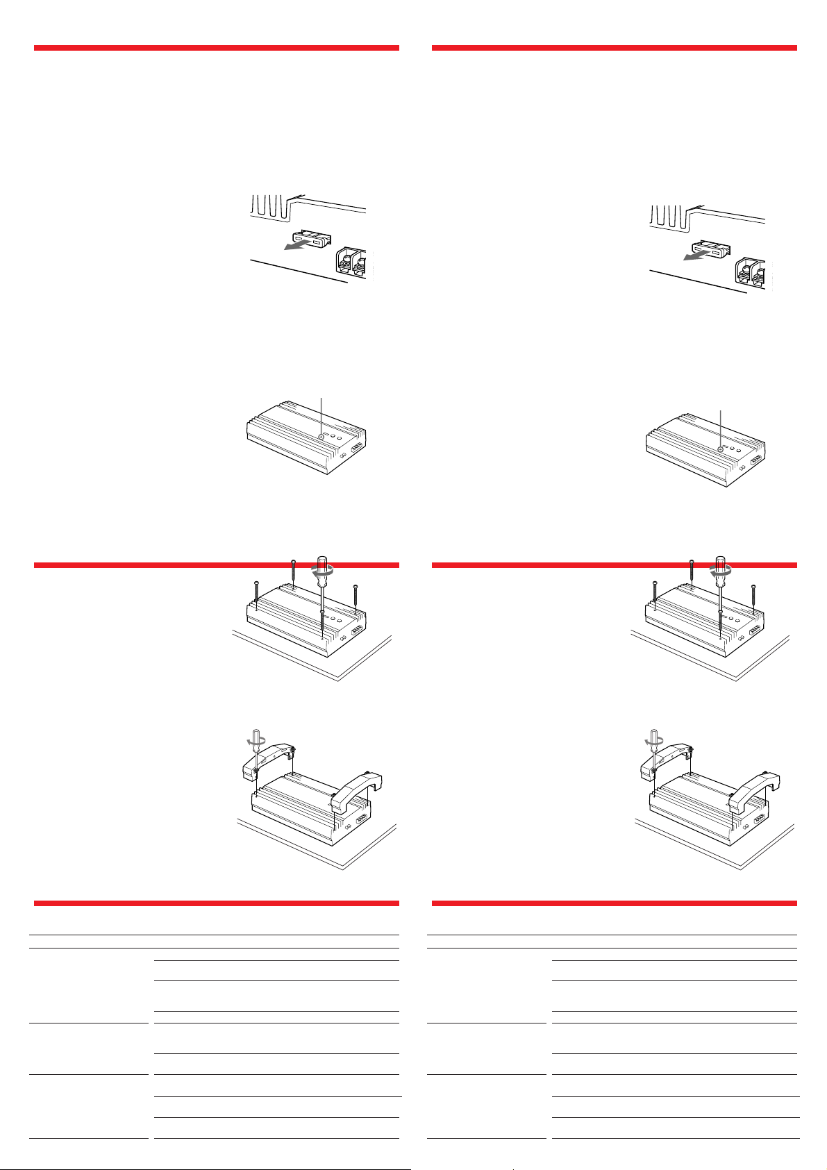
Fuse Replacement
If the fuse blows, check the power connection and
replace the fuse. If the fuse blows again after
replacement, there may be an internal
malfunction. In such a case, consult your nearest
Sony dealer.
Warning
When replacing the fuse, be sure to use one
matching the amperage stated above the fuse
holder. Never use a fuse with an amperage rating
exceeding the one supplied with the unit as this
could damage the unit.
∗Protection circuit
This amplifier is provided with a protection circuit that
operates in the following cases:
— when the unit is overheated
— when a DC current is generated
— when the speaker terminals are short circuited.
The color of the POWER/PROTECTOR indicator will
change from green to red, and the unit will shut down.
If this happens, turn off the connected equipment, take out
the cassette tape or disc, and determine the cause of the
malfunction. If the amplifier has overheated, wait until the
unit cools down before use.
POWER/PROTECTOR indicator
PrécautionsPrecaution
• Cet appareil est conçu pour fonctionner
uniquement sur courant continu de 12 volts
avec masse négative.
• Utilisez des haut-parleurs d’une impédance de
1 à 8 ohms (2 à 8 ohms lors de l’utilisation
comme amplificateur en pont).
• Ne raccordez pas de haut-parleurs actifs (avec
amplificateur intégré) aux bornes de hautparleurs de cet appareil; ils pourraient être
endommagés.
• N’exposez pas l’appareil:
— à des températures élevées, comme en plein
soleil ou près de la sortie d’air chaud du
chauffage;
— à l’humidité ou à la pluie;
— à la poussière ou à la saleté.
• Si votre voiture était garée en plein soleil et que
la température a considérablement augmenté à
l’intérieur, laissez refroidir l’appareil avant de
l’utiliser.
• Si vous installez l’appareil à l’horizontale, ne
recouvrez pas les ailettes de ventilation par le
tapis de sol ou autre chose.
• Si cet appareil est placé trop près de l’autoradio,
des interférences risquent de se produire.
Eloignez autant que possible l’amplificateur de
l’autoradio.
• Si le lecteur de cassette ou le tuner ne sont pas
alimentés, vérifiez tout d’abord les connexions.
• Cet amplificateur est équipé d’un circuit*
destiné à protéger les transistors et les haut-
parleurs en cas de défaillance. N’essayez pas de
tester l’efficacité de ce circuit en recouvrant les
dissipateurs thermiques ou en effectuant des
connexions inadéquates.
• N’utilisez pas l’appareil sur une batterie faible,
car sa performance maximale dépend d’une
bonne alimentation en électricité.
• Pour des raisons de sécurité, écoutez l’autoradio
à un volume modéré afin d’entendre les bruits
extérieurs.
Remplacement du fusible
Si le fusible saute, vérifiez les connexions du fil
d’alimentation et remplacez le fusible. S’il saute
de nouveau, un mauvais circuit interne peut en
être la cause. Dans ce cas, consultez votre
concessionnaire Sony.
Avertissement
En cas de remplacement du fusible, veillez à
utiliser un fusible dont l’intensité correspond à
celle inscrite sur le porte-fusible. N’utilisez jamais
de fusible dont l’intensité dépasse celle du fusible
fourni avec l’appareil, car vous risqueriez
d’endommager l’appareil.
* Circuit de protection
Cet amplificateur est équipé d’un circuit de protection qui
entre en service dans les cas suivants:
— Surchauffe de l’appareil
— Production d’un courant continu
— Court-circuit aux bornes des haut-parleurs.
La couleur du témoin POWER/PROTECTOR passe du vert
au rouge et l’appareil s’éteint.
Si le cas se présente, coupez l’alimentation de l’appareil
raccordé et éjecrez la cassette ou le disque compact avant
d’examiner la cause de la défaillance. Si l’amplificateur est
trop chaud, attendez qu’il refroidisse.
Témoin POWER/PROTECTOR
If you have any questions or problems
concerning your unit that are not covered in this
manual, please consult your nearest Sony dealer.
Installation Installation
Before Installation
• Mount the unit either inside the trunk or under
a seat.
• Choose the mounting location carefully so that
the unit will not interfere with the normal
movements of the driver and it will not be
exposed to direct sunlight or hot air from the
heater.
• Do not install the unit under the floor carpet,
where the heat dissipation from the unit will be
considerably impaired.
Firstly, place the unit where you plan to install it,
and mark the positions of the four screw holes on
the surface of the mounting board (not supplied).
Then drill the holes whose diameter should be
approximately 3 millimeters (mm) and mount the
unit onto the board with the supplied mounting
screws. The supplied mounting screws are 15
mm long. Therefore, make sure that the
mounting board is thicker than 15 mm.
After all the connections are completed, place the
cover on the unit with the supplied screws as
shown below.
Avant l'installation
• Installez l’appareil dans le coffre ou sous un
siège.
• Choisissez avec soin l’emplacement de sorte
que l’appareil ne gêne pas les mouvements du
conducteur et qu’il ne soit pas exposé au soleil
ou à l’air chaud du chauffage.
• N’installez pas l’appareil sous le tapis de sol car
la dissipation thermique ne pourrait pas se faire
correctement.
Présentez d’abord l’appareil à l’endroit où vous
voulez l’installer et tracez un repère de
positionnement pour les quatre vis sur la plaque
de montage (non fournie). Percez des trous
d’environ 3 millimètres (mm) de diamètre, puis
fixez l’appareil à l’aide des vis fournies. Celles-ci
font 15 mm de long; vérifiez, par conséquent, que
la plaque fait au moins 15 mm d’épaisseur.
Pour toute question ou problème qui ne serait pas
traité dans ce manuel, consultez votre
concessionaire Sony.
Une fois que toutes les connexions sont
terminées, installez le cache sur l’appareil à l’aide
des vis fournies, comme illustré ci-dessous.
Troubleshooting Guide
The following checklist will assist in the correction of most problems which you may encounter with your unit.
Before going through the checklist below, refer to the connection and operating procedures.
Problem
The POWER/PROTECTOR
indicator does not light up.
• The POWER/PROTECTOR
indicator flashes.
• The unit heats up abnormally.
Alternator noise is heard.
Cause/Solution
The fuse is blown. n Replace the fuse with a new one.
The ground lead is not securely connected. n Fasten the ground lead
securely to a metal point of the car.
The voltage going into the remote terminal is too low.
•
The connected master unit is not turned on. n Turn on the master unit.
• The system employs too many amplifiers. n Use a relay.
Check the battery voltage (10.5 – 16 V).
Use speakers with suitable impedance.
• Stereo operation: 1 – 8 Ω
• Bridging operation: 2 – 8 Ω
The speaker outputs are short-circuited. n Rectify the cause of the
short-circuit.
The power connecting leads are installed too close to the RCA pin
cables. n Keep the leads away from the cables.
The ground lead is not securely connected. n Fasten the ground lead
securely to a metal point of the car.
Negative speaker leads are touching the car chassis. n Keep the leads
away from the car chassis.
Guide de dépannage
La liste suivante vous aidera à résoudre la plupart des problèmes que vous pouvez rencontrer avec cet
appareil. Avant de passer la liste en revue, vérifiez les connexions et les procédures de fonctionnement.
Problème
Le témoin POWER/PROTECTOR
ne s’allume pas.
• Le témoin POWER/PROTECTOR
clignote.
• L’appareil chauffe
anormalement.
Le bruit de l’alternateur est
audible.
Cause/Solution
Le fusible a sauté. n Remplacez-le par un nouveau.
Le fil de masse n’est pas bien branché. n Fixez-le bien à une partie
métallique de la voiture.
La tension fournie à la borne de télécommande est trop faible.
• L’appareil raccordé n’est pas sous tension. n Mettez-le sous tension.
• Le système utilise trop d’amplificateurs. n Utilisez un relais.
Vérifiez la tension de la batterie (10,5 – 16 V).
Utilisez des haut-parleurs d’une impédance adéquate.
• Fonctionnement en stéréo: 1 – 8 Ω
• Fonctionnement en pont: 2 – 8 Ω
Les sorties de haut-parleur sont court-circuitées. n Supprimez la
cause du court-circuit.
Les fils de connexion sont trop près des cordons à broche RCA. n
Eloignez les fils des cordons.
Le fil de masse n’est pas bien raccordé. n Fixez solidement le fil de
masse à une partie métallique de la voiture.
Les fils de haut-parleurs négatifs touchent le châssis de la voiture. n
Eloignez les fils du châssis de la voiture.
Page 3

Connections
Connexions
Caution
• Before making any connections, disconnect the
ground terminal of the car battery to avoid short
circuits.
• Be sure to use speakers with an adequate power
rating. If you use small capacity speakers, they
may be damaged.
• Do not connect the ’ terminal of the speaker
system to the car chassis, and do not connect the
’ terminal of the right speaker with that of the
left speaker.
• Install the input and output cords away from the
power supply lead as running them close
together can generate some interference noise.
• This unit is a high powered amplifier. Therefore,
it may not perform to its full potential if used
with the speaker cords supplied with the car.
• If your car is equipped with a computer system
for navigation or some other purpose, do not to
remove the ground wire from the car battery. If
you disconnect the wire, the computer memory
may be erased. To avoid short circuits when
making connections, disconnect the +12 V
power supply lead until all the other leads have
been connected.
Make the terminal
connections as illustrated below.
Attention
• Avant d’effectuer les connexions, débranchez le
fil de masse de la borne de la batterie pour éviter
un court-circuit.
• Utilisez des haut-parleurs d’une capacité
adéquate. Si vous utilisez des haut-parleurs de
faible capacité, ils risquent d’être endommagés.
• Ne raccordez pas la borne ’ des haut-parleurs à
la carrosserie de la voiture ni la borne ’ du
haut-parleur droit à celle du haut-parleur
gauche.
• Eloignez les cordons d’entrée et de sortie du fil
d’alimentation électrique pour éviter que des
interférences ne se produisent.
• Cet appareil est un amplificateur de haute
puissance et il peut ne pas atteindre sa puissance
maximale si les cordons de haut-parleurs
originaux de la voiture lui sont raccordés.
• Si la voiture est équipée d’un ordinateur de
navigation ou d’un autre appareil, ne
débranchez pas le fil de masse de la batterie de
la voiture, sinon les données mémorisées seront
effacées. Pour éviter un court-circuit lorsque
vous effectuez les branchements, branchez le fil
d’alimentation de +12 volts uniquement après
avoir branché tous les autres fils.
Effectuez les connexions de la
manière indiquée ci-dessous.
2-Speaker System
Système à 2 haut-parleurs
FILTER
OFFHPF LPF
Car audio
Autoradio
LINE OUT
Right speaker
(min. 1Ω)
Haut-parleur
droit
(min. 1Ω)
80Hz80Hz
50Hz
As a Monaural Amplifier
Utilisation comme amplificateur mono
Car audio
Autoradio
LINE OUT
FILTER
OFFHPF LPF
80Hz80Hz
Right channel
Canal droit
50Hz
Left channel
Canal gauche
FILTER
OFFHPF LPF
Left speaker
(min. 1Ω)
Haut-parleur
gauche
(min. 1Ω)
80Hz80Hz
50Hz
Note
When you tighten the screw, be careful not to apply too much
torque* as doing so may damage the screw.
* The torque value should be less than 1 N•m.
Remarque
*
pas trop fort la vis car vous pourriez l’endommager.
Ne serrez
* Le couple de serrage devrait être inférieur à 1 N•m.
Power Connection Leads (not supplied)
Fils d'alimentation électrique (non fournis)
to REM OUT on the amplifier **
vers REM OUT sur l‘amplificateur **
REM OUT
Car audio
Autoradio
* (XM-4026)
** If you have the factory original or some other car audio without a remote out-put on the amplifier, connect the remote input
terminal (REMOTE) to the accessory power supply.
** Si vous disposez du modèle d’origine ou d’un autre autoradio dont l’amplificateur ne comporte pas de sortie de télécommande,
raccordez la borne d’entrée de télécommande (REMOTE) à la prise d’alimentation accessoires.
Notes on the power supply
• Connect the +12 V power supply lead only after all the other
leads have been connected.
• Be sure to connect the ground lead of the unit
securely to a metal point of the car. A loose
connection may cause a malfunction of the
amplifier.
• Be sure to connect the remote control lead of the car audio to
the remote terminal.
• When using a car audio without a remote output on the
amplifier, connect the remote input terminal (REMOTE) to
the accessory power supply.
• Use the power supply lead with a fuse attached (30 (20)* A).
• Place the fuse in the power supply lead as close as possible to
the car battery.
• Make sure that the leads to be connected to the + 12 V and
GND terminals of this unit respectively must be larger than
12 (14)*-Gauge (AWG-12 (14)*) or with the sectional area
of more than 3 (2)* mm
*(XM-4026)
2
.
Fuse (30 (20)* A)
Fusible (30 (20)* A)
Remarques sur l’alimentation électrique
• Raccordez le fil d’alimentation de +12 volts uniquement
après avoir avoir réalisé toutes les autres connexions.
• Raccordez solidement le fil de masse de l’appareil à
une partie métallique de la voiture, car une
connexion lâche peut être à l’origine d’une
défaillance de l’amplificateur.
• Assurez-vous que le fil de télécommande de l’autoradio est
raccordé à la borne de télécommande.
• Si vous utilisez un autoradio dont l’amplificateur ne
comporte pas de sortie de télécommande, raccordez la borne
d’entrée de télécommande (REMOTE) à la prise
d’alimentation accessoires.
• Utilisez un fil d’alimentation équipé d’un fusible d’au moins
30 (20)* ampères.
• Fixez le fusible du fil d’alimentation électrique le plus près
possible de la batterie de la voiture.
• Vous devez raccorder des fils de calibre supérieur à 12 (14)*
(AWG-12 (14)*) ou d’une section supérieure à 3 (2)* mm
aux bornes +12V et GND.
*(XM-4026)
to a metal point of the car
à un point métallique de la
voiture
+ 12 V car battery
Batterie de voiture de + 12 V
Right speaker (min. 2Ω)
Haut-parleur droit (min. 2Ω)
Note
Make sure that the line output from the car audio is
connected to the jack marked “R (MONO)” on the unit.
Remarque
Vérifiez que la sortie de ligne de l’autoradio est raccordée à
la prise portant l’indication “R (MONO)” sur l’appareil.
Left speaker (min. 2Ω)
Haut-parleur gauche (min. 2Ω)
As the Monaural Amplifier for a Subwoofer
Utilisation comme amplificateur mono pour un subwoofer
You can select your desired
Car audio
Autoradio
LINE OUT
Subwoofer (min. 2Ω)
Subwoofer (min. 2Ω)
Note
If you wish to use a subwoofer as a monaural speaker,
connect the speaker as illustrated above. The output
signals to the subwoofer will be the combination of the
both right and left output signals.
2
FILTER
Remarque
Si vous souhaitez utiliser un subwoofer comme hautparleur mono, raccordez le haut-parleur comme indiqué
sur l'illustration ci-dessous. Les signaux de sortie du
subwoofer sont constitués des signaux de sortie des
canaux gauche et droit.
frequency of the LPF side (50 Hz
OFFHPF LPF
or 80 Hz).
80Hz80Hz
50Hz
Vous pouvez sélectionner la
fréquence voulue pour le côté LPF
(50 Hz ou 80 Hz).
Page 4

Dual Mode System (With a Bridged Subwoofer)
Double mode de connexion (avec subwoofer en pont)
FILTER
OFFHPF LPF
Car audio
Autoradio
LINE OUT
80Hz80Hz
50Hz
2-way System
Système à 2 voies
FILTER
OFFHPF LPF
Car audio
Autoradio
LINE OUT
80Hz80Hz
50Hz
FILTER
OFFHPF LPF
80Hz80Hz
50Hz
You can select your desired
frequency of the LPF side
(50 Hz or 80 Hz).
Vous pouvez sélectionner
la fréquence voulue pour le
côté LPF (50 Hz ou 80
Hz).
Right speaker
Haut-parleur droit
Table of crossover values for
6 dB/octave (4 ohms)
Crossover
Frequency
unit: Hz
50
80
100
130
150
200
260
400
600
800
1000
L
(coil)
unit: mH
12.7
8.2
6.2
4.7
4.2
3.3
2.4
1.6
1.0
0.8
0.6
* (not supplied)
Notes
• When using passive crossover networks in a multi-speaker
system, care must be taken as the speaker system’s impedance
should not be lower than that of the suitable impedance for
this unit.
• When you are installing a 12 decibels/octave system in your
car, the following points must be considered. In a 12
decibels/octave system where both a choke and capacitor are
used in series to form a circuit, a great care must be taken
when they are connected. In such a circuit, there is going to
be an increase in the current which by-passes the speaker
with frequencies at around the crossover frequency. If audio
signals are continued to be fed into the crossover frequency
area, it may cause the amplifier to become abnormally hot or
the fuse will be blown. Also if the speaker is disconnected, a
series-resonant circuit will be formed by the choke and the
capacitor. In this case, the impedance in the resonance area
will decrease dramatically resulting in a short circuit like
situation causing a damage to the amplifier. Therefore, make
sure that a speaker is connected to such a circuit at all times.
C1/C2
*
(capacitor)
unit: µF
800
500
400
300
270
200
150
100
68
50
39
C2C1
Left speaker
L
Subwoofer
Subwoofer
Haut-parleur gauche
Tableau des valeurs de recoupement pour
6 dB/octave (4 ohms)
Fréquence de
*
recoupement
unité: Hz
50
80
100
130
150
200
260
400
600
800
1000
* (non fournis)
Remarques
• Quand vous utilisez des circuits de recoupement de
fréquence passifs dans un système à plusieurs haut-parleurs,
assurez-vous que l’impédance du système n’est pas inférieure
à celle prévue pour cet appareil.
• Si vous installez un système à 12 décibels/octave dans votre
voiture, vous devez respecter les points suivants:
Dans un système à 12 décibels/octave où la bobine d’arrêt et
le condensateur sont utilisés en série pour former un circuit,
vous devez réaliser les branchements avec beaucoup de
précaution. Dans ce type de circuit, une augmentation du
courant contournant le haut-parleur se produit dans les
fréquences se situant autour de la fréquence de coupure. Si
des signaux audio continuent d’être fournis dans la zone de
la fréquence de recoupement, une surchauffe risque de se
produire dans l’amplificateur et le fusible de sauter. Si le
haut-parleur n’est pas raccordé, un circuit de résonance série
sera créé par la bobine et le condensateur. Dans ce cas,
l’impédance dans la zone de résonance sera considérablement
réduite, et comme dans le cas d’un court-circuit,
l’amplificateur peut être endommagé. Par conséquent, veillez
à ce qu’un haut-parleur soit toujours raccordé au circuit.
L
(bobine)
unité:mH
12,7
8,2
6,2
4,7
4,2
3,3
2,4
1,6
1,0
0,8
0,6
*
C1/C2
(condensa-
teur)*
unité: µF
800
500
400
300
270
200
150
100
68
50
39
Full range speakers
(min. 1Ω)
Haut-parleurs à
large bande
(min. 1Ω)
Note
In this system, the volume of the subwoofers will be
controlled by the car audio fader control.
Level Adjustment
Control
The input level can be adjusted with this control
when using source equipment of other
manufacturers. Turn it to MAX when the output
level of the car audio seems low.
XM-5026XM-5026/4026
Subwoofers
(min. 1Ω)
Subwoofers
(min. 1Ω)
Remarque
Dans ce système, le volume des subwoofers est contrôlé
par la commande de balance avant-arrière de l’autoradio.
Commande de réglage
de niveau
Le niveau d’entrée peut être modifié par cette
commande. Utilisez-la pour ajuster le niveau
d’entrée du son quand vous utilisez un appareil
d’un autre fabricant. Réglez-la sur MAX si le
niveau de sortie de l’autoradio semble trop faible.
LEVEL
MAXMIN
LOW BOOST Level
Control
Turn this control to boost the frequencies around
40 Hz at the maximum of 10 dB. The low boost
response curve is shown below.
dB
(XM-5026 Only)
10
0
10
40 100 1k
FREQUENCY
Hz
Commande LOW BOOST
(XM-5026 uniquement)
Tournez cette commande pour accentuer les
fréquences autour de 40 Hz jusqu’à 10 dB
maximum. La courbe de réponse de
l’accentuation des basses fréquences est illustrée
ci-dessous.
LOW BOOST(40Hz)
+10dB0dB
 Loading...