


5-038-863-12(1)
4-Channel Power
Amplifier
Operating Instructions
Mode d’emploi
Bedienungsanleitung
Manual de instrucciones
Gebruiksaanwijzing
Bruksanvisning
GB
FR
DE
ES
NL
SE
Owner’s Record
The model and serial numbers are located on the bottom of the unit.
Record the serial number in the space provided below.
Refer to these numbers whenever you call upon your Sony dealer
re
garding this product.
Model No. XM-4ES
Serial No.
XM-4ES

For your safety, be sure to install this unit inside
t
he trunk (boot) or under the seat.
For details, see “Installation and Connection”
(page 7).
Made in Thailand
The nameplate indicating operating voltage, etc., is
l
ocated on the bottom of the chassis.
The validity of the CE marking is restricted to only
t
hose countries where it is legally enforced, mainly
in the countries EEA (European Economic Area) and
Switzerland. The validity of the UKCA marking is
restricted to only those countries where it is legally
enforced, mainly in the UK.
Notice for customers: the following
information is only applicable to equipment
sold in countries applying EU directives
This product has been manufactured by or on
behalf of Sony Corporation.
EU Importer: Sony Europe B.V.
Inquiries to the EU Importer or related to product
c
ompliance in Europe should be sent to the
manufacturer’s authorized representative, Sony
Belgium, bijkantoor van Sony Europe B.V., Da
Vincilaan 7-D1, 1930 Zaventem, Belgium.
Disposal of waste batteries and
electrical and electronic equipment
pplicable in the European Union
(a
and other countries with separate
collection systems)
This symbol on the product, the battery or on the
packaging indicates that the product and the
battery shall not be treated as household waste.
On certain batteries this symbol might be used in
c
ombination with a chemical symbol. The chemical
symbol for lead (Pb) is added if the battery contains
more than 0.004% lead.
By ensuring that these products and batteries are
d
isposed of correctly, you will help to prevent
potentially negative consequences for the
environment and human health which could be
caused by inappropriate waste handling. The
recycling of the materials will help to conserve
natural resources.
In case of products that for safety, performance or
da
ta integrity reasons require a permanent
connection with an incorporated battery, this
battery should be replaced by qualified service staff
only.
To ensure that the battery and the electrical and
el
ectronic equipment will be treated properly, hand
over these products at end-of-life to the
appropriate collection point for the recycling of
electrical and electronic equipment.
For all other batteries, please view the section on
ho
w to remove the battery from the product safely.
Hand the battery over to the appropriate collection
point for the recycling of waste batteries.
For more detailed information about recycling of
th
is product or battery, please contact your local
Civic Office, your household waste disposal service
or the shop where you purchased the product or
battery.
If you have any questions or problems concerning
yo
ur unit that are not covered in this manual,
consult your nearest Sony dealer.
2GB

Features
•Rated power output of 100 W (at 4 Ω) and 165 W
(at 2 Ω).
•Class D Technology*
•For car audio units without a line output, direct
connection (High Level Input Connection) to the
speaker output of your car audio unit can be made
using a speaker-wire-to-RCA adaptor (not
supplied).
•High-level sensing turn-on feature allows this unit
t
o be activated without the need for a REMOTE
connection.
•Built-in HP (high-pass), LP (low-pass), and BP
(b
and-pass) filter for front and rear channel.
•Protection circuit and indicator provided.
•Pulse power supply*
output power.
*1 Class D Technology
The Class D Technology is a method to convert and
amplify music signals with MOSFETs to high-speed pulse
signals. Furthermore, it features high efficiency and low
heat generation.
*2 P
ulse power supply
This unit has a built-in power regulator which converts
he power supplied by the 12 V DC car battery into high-
t
speed pulses using a semiconductor switch. These
pulses are stepped up by the built-in pulse transformer
and separated into both positive and negative power
supplies before being converted into direct current
again. This is to regulate fluctuating voltage from the car
battery. This lightweight power supply system provides a
highly efficient power supply with a low impedance
output.
1
2
for stable and regulated
3GB

Table of Contents
Features . . . . . . . . . . . . . . . . . . . . . . . . . . . . . . . . . . . 3
Guide to Parts and Controls
Power Amplifier. . . . . . . . . . . . . . . . . . . . . . . . . . . . . 5
Installation and Connection
Parts for Installation and Connection . . . . . . . . . . . 7
Installation . . . . . . . . . . . . . . . . . . . . . . . . . . . . . . . . . 7
Connection. . . . . . . . . . . . . . . . . . . . . . . . . . . . . . . . . 8
Additional Information
Precautions . . . . . . . . . . . . . . . . . . . . . . . . . . . . . . . 13
Maintenance . . . . . . . . . . . . . . . . . . . . . . . . . . . . . . 13
Specifications . . . . . . . . . . . . . . . . . . . . . . . . . . . . . 14
Troubleshooting . . . . . . . . . . . . . . . . . . . . . . . . . . . 15
Support Site . . . . . . . . . . . . . . . . . . . . . . . . . . . . . . . 15
4GB
Guide to Parts and Controls
TURN-ON
REMOTE SIGNAL
INPUT MODE
1-4
11-2
1+3/2+4
FILTER
CH 1/2
BRIDGED
OFF BP
HP LP
CH 1 CH 2
LINE OUT MODE
THRU ALL
STEREO
INPUT SENS
FILTER
CH 3/4
OFF BP
HP LP
INPUT SENS
BRIDGED
CH 3 CH 4
L R L R
REMOTE+12 V
GROUND
TURN-ON
REMOTE SIGNAL
INPUT MODE
1-4
11-2
1+3/2+4
FILTER
CH 1/2
BRIDGED
OFF BP
HP LP
CH 1 CH 2
LINE OUT MODE
THRU ALL
STEREO
INPUT SENS
50500
FILTER RANGE (Hz)
CH 3/4
HPF (Hz)
OFF BP
HP LP
500-
5k
500
150
50050
1.5k
LPF (Hz)
500
150
50050
5k
1.5k
INPUT SENS
BRIDGED
CH 3 CH 4
L R L R
REMOTE
+
12 V
GROUND
5k
50500
RANGE (Hz) HPF (Hz)
500-
5k
500
150
50050
1.5k
LPF (Hz)
500
150
50050
5k
1.5k
5k
50500
RANGE (Hz) HPF (Hz)
500-
5k
500
150
50050
1.5k
LPF (Hz)
500
150
50050
5k
1.5k
5k
50500
RANGE (Hz) HPF (Hz)
500-
5k
500
150
50050
1.5k
LPF (Hz)
500
150
50050
5k
1.5k
5k
ȫ Ȭ ȭ Ȯ ȯ Ȱ ȱ Ȳ Ȯ ȯ Ȱ ȱ Ȳ
Ȫ
ȳ ȴ
ȩ
INPUT 1 CH 1
INPUT 2 CH 2
INPUT 3 CH 3
INPUT 4 CH 4
INPUT 1 CH 1
CH 2
CH 3
CH 4
INPUT 1 CH 1
CH 3
INPUT 2 CH 2
CH 4
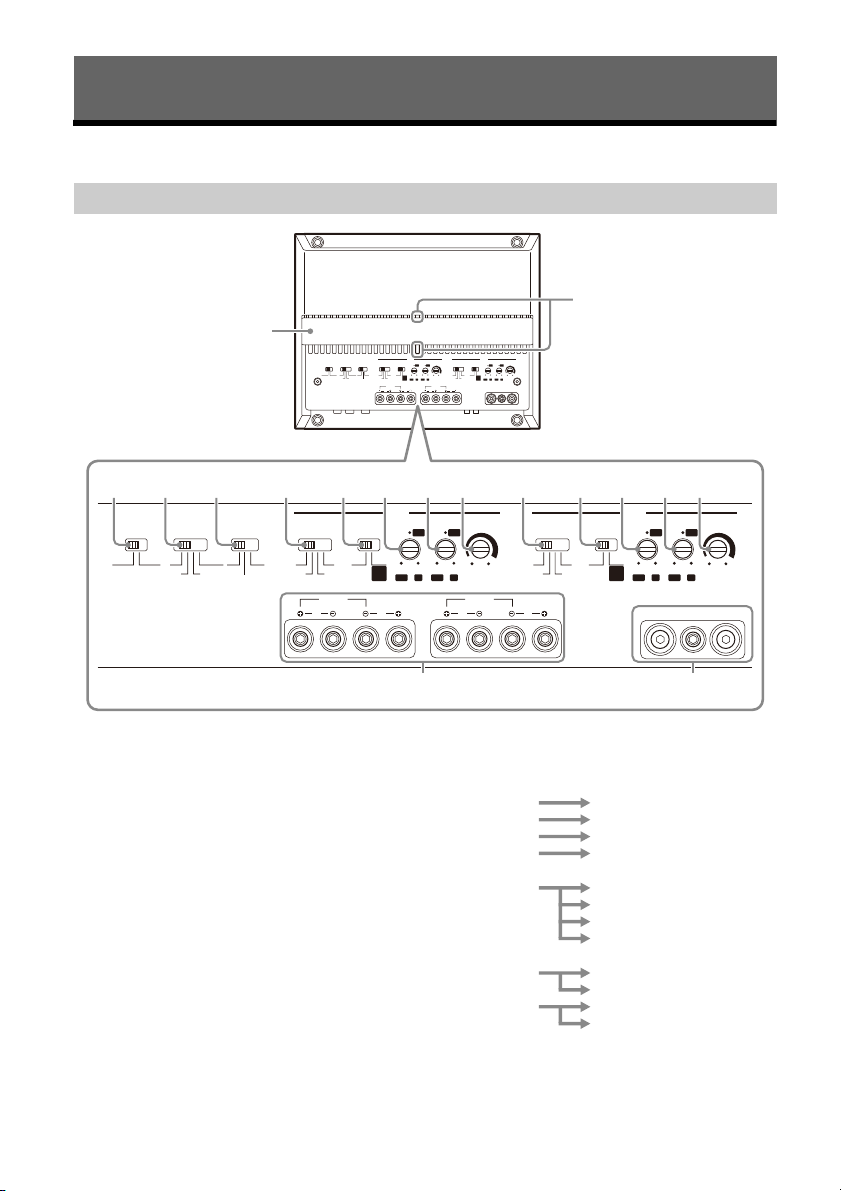
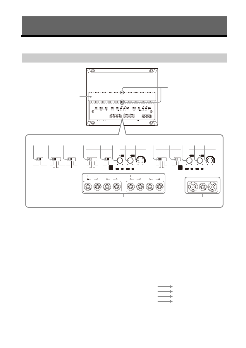
Power Amplifier
Control Panel (Top Panel)
Heat sink cover
The direction of the heat sink cover can be
c
hanged according to your preference (page 7).
S
tatus indicator light
Lights up in white during operation.
If the protection circuit activates, the status
in
details, see “Troubleshooting” (page 15).
TU
dicator light changes from white to red. For
RN-ON switch
IN
PUT MODE switch
Selects the input mode.
• “1-4”: For 4-channel stereo input.
• “1”: For 1-channel input.
Selects the turn-on mode of the amplifier.
• “REMOTE”: Select this for remote turn-on
m
ode. The amplifier turns on when a turn-on
signal is received from the REMOTE terminal.
See “REMOTE terminal” (page 9) for details.
• “SIGNAL”: Select this for high-level sensing
t
urn-on mode. The amplifier turns on when a
turn-on signal is received from the INPUT
connector. This feature is only available for
high-level (speaker level) input connection.
See “REMOTE terminal” (page 9) for details.
• “1-2”: For 2-channel input.
5GB
• “1+3/2+4”: For 4-channel input.
INPUT 1 CH 1
INPUT 3 CH 3
INPUT 2 CH 2
INPUT 4 CH 4
INPUT 1
INPUT 2 LINE OUT 1
INPUT 3 LINE OUT 2
INPUT 4
13
L
REMOTE
+
12 V
GROUND
40 A 40 A
INPUT
VOLTAGE
LOW HIG H
INPUT SPEAKER OUTLINE OUT
CH 1
CH 2
1
24 2
R
BRIDGED
L R
CH 3 CH 4
BRIDGED
L R
ȵ ȶ ȷ ȸ ȹȺ
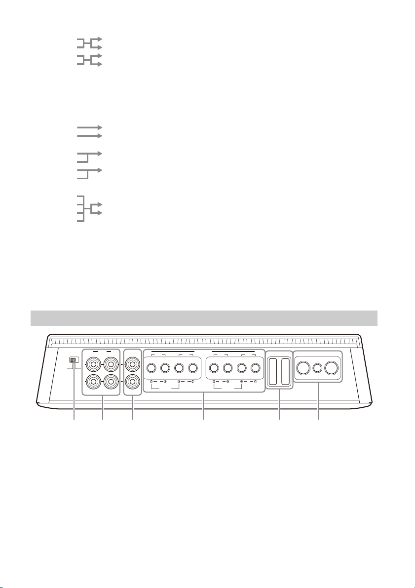
NE OUT MODE switch
LI
Sets the mode of signal output to LINE OUT 1
a
nd 2 connectors. Signal output from all LINE
OUT connectors are unfiltered and not affected
by any FILTER settings.
• “THRU”: Stereo output (through mode)
INPUT 1 LINE OUT 1
INPUT 2 LINE OUT 2
• “STEREO”: Stereo output (summing mode)
INPUT 1 LINE OUT 1
INPUT 3
INPUT 2 LINE OUT 2
INPUT 4
• “ALL”: Mono output (summing mode)
FI
LTER switch
Sets the filter mode for CH 1/2 and CH 3/4.
• “OFF”: Turns the filter off.
• “HP” (high-pass): Frequencies lower than HPF
c
ontrol setting are filtered.
• “LP” (low-pass): Frequencies higher than LPF
c
ontrol setting are filtered.
• “BP” (band-pass): The range of frequency for
t
he HPF control is automatically fixed at 50 Hz
– 500 Hz; the range of frequency for LPF
control is automatically fixed at 500 Hz – 5
kHz. Frequencies outside the range of HPF
and LPF settings are filtered.
RA
NGE switch
Sets the range of frequency for HPF (high-pass
f
ilter) and LPF (low-pass filter) control.
• “50-500”: Range of frequency for subwoofer.
• “500-5k”: Range of frequency for midrange
s
peaker or tweeter.
H
PF (high-pass filter) control
Depending on the RANGE setting, adjusts the
c
utoff frequency in the range of 50 Hz – 500 Hz
or 500 Hz – 5 kHz.
L
PF (low-pass filter) control
Depending on the RANGE setting, adjusts the
c
utoff frequency in the range of 50 Hz – 500 Hz
or 500 Hz – 5 kHz.
I
NPUT SENS (input sensitivity) control
Adjusts the input level sensitivity for CH 1/2 and
CH
3/4. Turn the knob clockwise when the
output level of the connected audio devices is
low.
SPE
AKER OUT terminal screw head
+12
V terminal screw head
REMOTE terminal screw head
GROUND terminal screw head
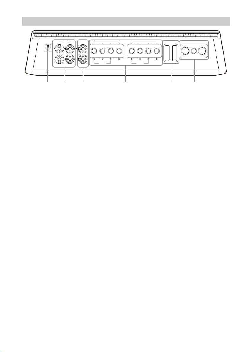
Connector Panel (Front Panel)
INP
UT VOLTAGE switch
Selects the type of input connection.
• “LOW”: Select this for low-level (line level)
i
nput connection using RCA extension cables
(not supplied).
• “HIGH”: Select this for high-level (speaker
le
vel) input connection using a speaker-wire-
to-RCA adaptor (not supplied).
INP
6GB
UT connector
For details about the connection, see “Input
Connection” (page 9).
INE OUT connector
L
For details about the connection, see “Output
Connection” (page 12).
SPE
AKER OUT terminal
For details about the connection, see “Speaker
Connection” (page 11).
Fu
se (40 A)
+12 V
terminal
REMOTE terminal
GROUND terminal
Installation and Connection
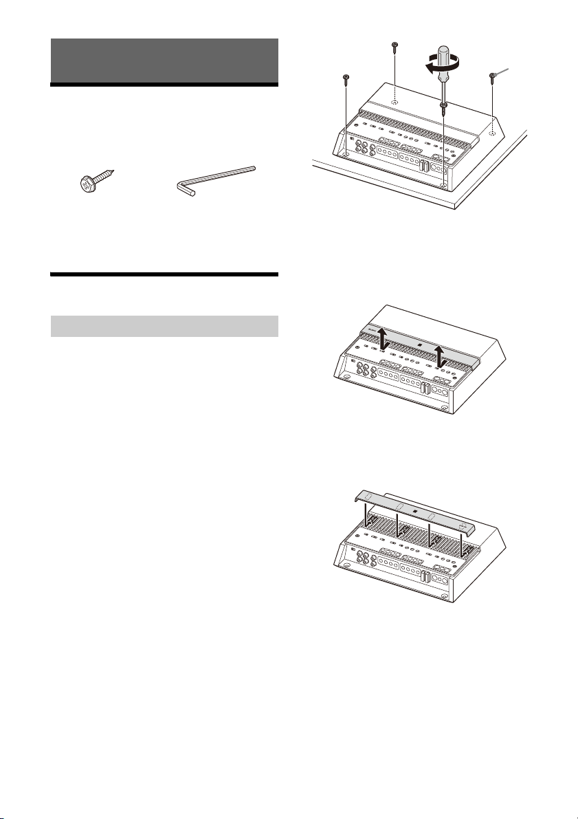
Parts for Installation and
Connection
Mount ing screw
(5 × 20 mm (
7
/32 × 13/16 in)) (4)
x key (2.5 mm (3/32 in)) (1)
He
This parts list does not include all the package
contents.
Installation
Installing the Amplifier
•Mount the amplifier either inside the trunk (boot)
or under a seat.
•For your safety, choose a mounting location that
w
ill not interfere with any driving operations.
•Do not install the amplifier near the heater, in
a
reas that get exposed to direct sunlight, or
subject to high temperature.
•Do not install the amplifier under a floor carpet
w
here the heat dissipation from the amplifier will
be considerably impaired.
•Avoid installing the amplifier in areas subject to
r
ain, moisture, dust and dirt.
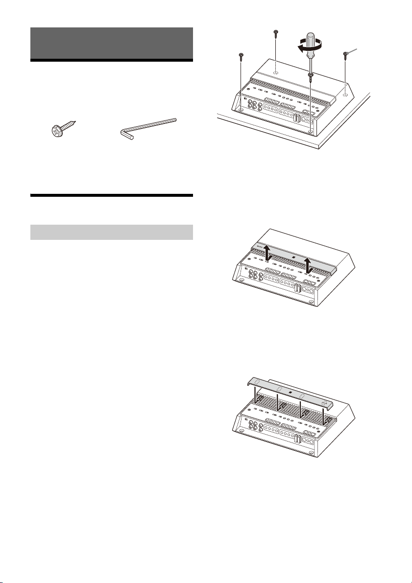
Mounting the amplifier
Place the amplifier on your selected
1
mounting location, then mark the position
of the 4 screw holes on a mounting board
(not supplied).
2 Drill a 3 mm (
and mount the amplifier onto the board
with the mounting screws .
The mounting screws are 20 mm (13/16 in)
long, so make sure that the mounting board is
thicker than 20 mm (
1
/8 in) pilot hole at each mark
13
/16 in).
Changing the heat sink cover direction
The direction of the heat sink cover can be changed
according to your preference.
1 Slide the cover forward, then lift to remove
it.
2 Rotate the cover to your desired direction.
3 Align the cover to the catches on the
amplifier, then slide the cover back until it
clicks into place.
7GB
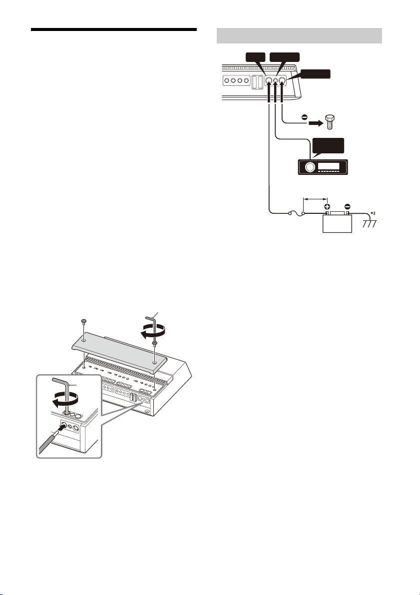
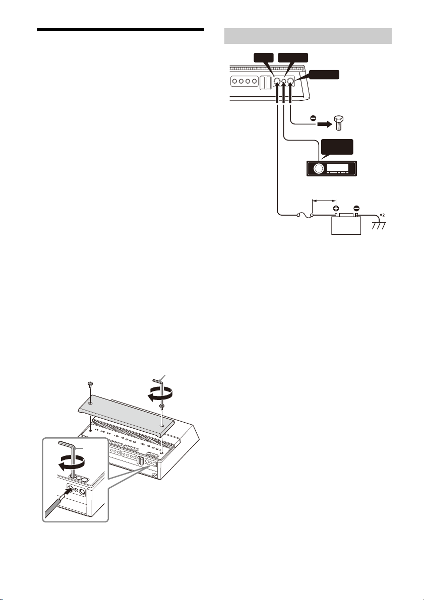
Connection
REMOTE
OUT*
1
+12 V REMOTE
GROUND
Fuse (80 A)
to a metal point
on the car chassis
less than 450 mm (1 7 3/4 in)
•Before making any connections, disconnect the
ground (earth) terminal of the car battery to avoid
short circuits. Connect this amplifier to the +12 V
power supply lead only after all other leads have
been connected.
•This amplifier is designed
(earth) 12 V DC operation only.
•Do not operate the amplifier on a weak battery as
th
e amplifier requires a good power supply for
optimum performance.
•If your car is equipped with a computer system for
p
urposes such as navigation, disconnecting the
ground (earth) terminal of the car battery may
damage the computer memory. Leave the ground
(earth) lead connected and connect this amplifier
to the +12 V power supply lead only after all other
leads have been connected to prevent short
circuits.
• When connecting and installing the input and
out
put cables, keep them away from the +12 V
power supply lead. Running them close together
may generate interference noise.
Notes on making connections
• To connect to the terminals on the connector
panel and to adjust various settings, remove the
top cover to access the control panel (top panel).
•When you tighten the screw, be careful not to
a
pply too much torque as doing so may damage
the terminals or cables.
+
12 V
REMOTE
GROUND
+
12 V
REMOTE
GROUND
for negative ground
Power Connections
*1 If you have the factory original or some other car audio
unit without a remote output for the amplifier, connect
the remote input (REMOTE) terminal to the ACC power
supply. In high level input connection, the amplifier can
also be activated without a need for REMOTE connection.
However, this function is not guaranteed for all car audio
units.
*2 Ground (earth) to the car chassis.
+12 V terminal
•Connect the +12 V power supply lead to the +12 V
terminal only after all the other connections have
been completed.
•Use a +12 V power supply lead with a 80 A fuse
at
tached.
•During full-power operation, a current of more
t
han 80 A will run through the system. Therefore,
make sure the leads to be connected to the +12 V
t
erminal are at least 4-Gauge (AWG-4) or have a
sectional area of more than 22.0 mm² (
• All power leads connected to the positive battery
p
ost should be fused within 450 mm (17
the battery post before they pass through any
metal.
•Make sure the leads connecting from the car
b
attery to the metal point on the car chassis are at
least of a lead gauge equal to that of the +12 V
power supply lead connected from the battery to
the amplifier.
•Make sure the leads connecting from the car
b
attery to the metal point on the car chassis are
not more than 0-Gauge (AWG-1/0) or have a
sectional area of 55 mm² (2
5
/16 in²), and at least
of a lead gauge equal to that of the +12 V power
supply lead connected from the battery to the
amplifier.
7
/8 in²).
3
/4 in) of
8GB
GROUND terminal
INPUT
VOLTAGE
LOW HIGH
*
INPUT
VOLTAGE
LOW HIGH
*
Speaker output
(left)
Speaker output
(right)
•Be sure to connect the ground (earth) lead
securely to a metal point on the car chassis. A
loose connection may cause the amplifier to
malfunction.
•During full-power operation, a current of more
t
han 80 A will run through the system. Therefore,
make sure the leads to be connected to the
GROUND terminal are at least 4-Gauge (AWG-4) or
have a sectional area of more than 22.0 mm²
7
(
/8 in²).
REMOTE terminal
•To turn on the amplifier using a dedicated remote
turn-on lead, set the TURN-ON switch to
“REMOTE”, then connect the remote output
(REMOTE OUT) of your car audio unit to the
REMOTE terminal.
•When using a car audio unit without a remote
o
utput (REMOTE OUT) for the amplifier, connect
the REMOTE terminal to the ACC power supply of
your car or use the signal sensing turn-on setting
instead.
• Use a remote turn-on lead with a thickness from
A
WG-8 to AWG-18 or a sectional area from
8.4 mm² (
Notes on using high-level sensing turn-on
settings
• In high level input connection, the amplifier can
also be activated without the need for a REMOTE
connection. However, this function is not
guaranteed for all car audio units.
•By setting the TURN-ON switch to “SIGNAL”, the
a
signal is received from the INPUT connector.
11
/32 in²) to 0.82 mm² (1/16 in²).
mplifier operates automatically when a turn-on
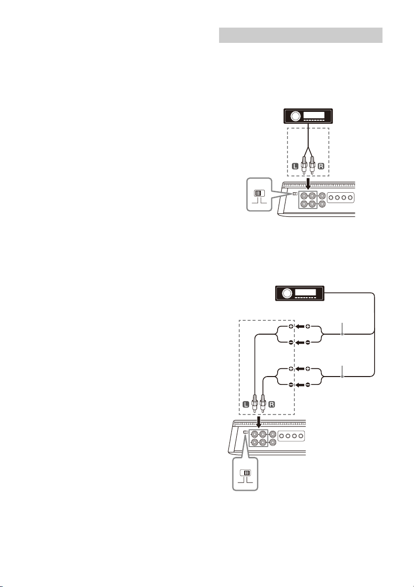
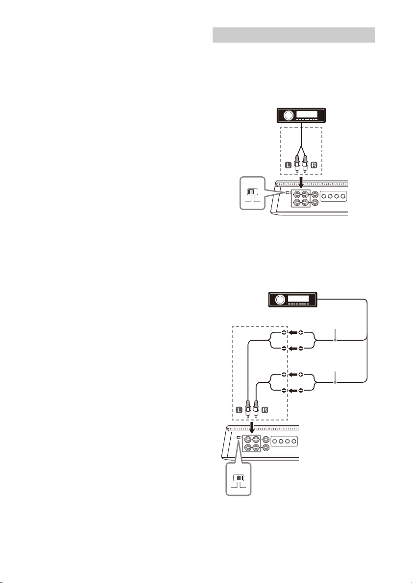
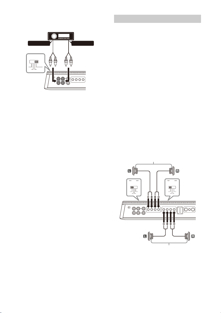
Input Connection
The INPUT connector can be used by both low-level
nput and high-level input.
i
Making low-level input connection
Set the INPUT VOLTAGE switch to “LOW” and
connect the RCA cable (not supplied) from your car
audio to the INPUT connector.
* RCA cable (not supplied)
Making high-level input connection
Set the INPUT VOLTAGE switch to “HIGH” and use a
speaker-wire-to-RCA adaptor (not supplied) to
connect the speaker wire from your car audio to the
INPUT connector.
* Speaker wire-to-RCA adaptor (not supplied)
9GB
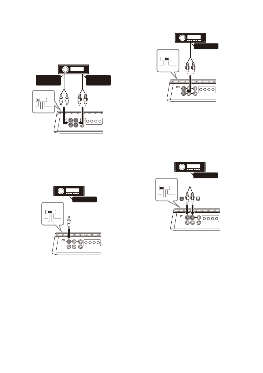
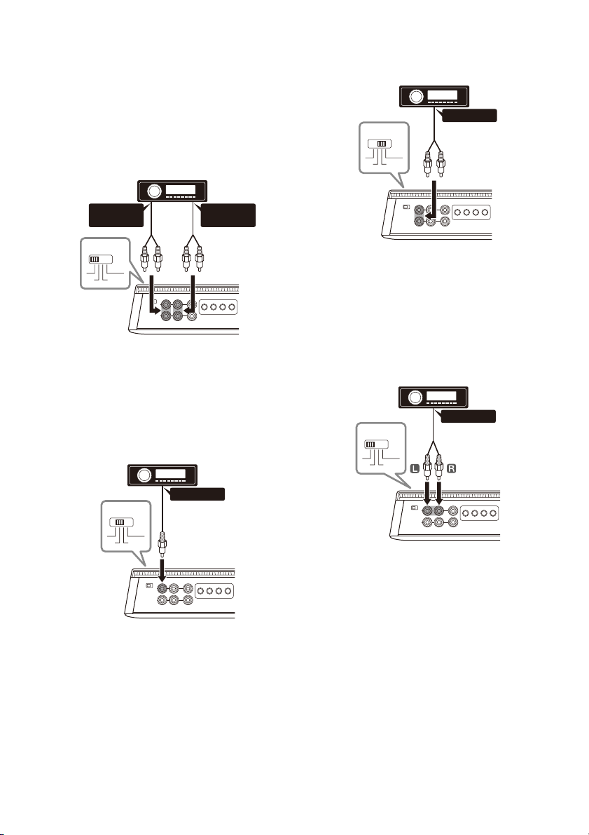
The following shows the connection and settings
FRONT
AUDIO OUT
REAR
AUDIO OUT
INPUT MODE
1-4
11-2
1+3/2+4
**
AUDIO OUT
INPUT MODE
1-4
11-2
1+3/2+4
*
AUDIO OUT
INPUT MODE
1-4
11-2
1+3/2+4
*
AUDIO OUT
INPUT MODE
1-4
11-2
1+3/2+4
*
typically used when connecting a car audio unit and
this amplifier. Refer to the operating instructions
supplied with your car audio for more details about
the input connection for your car audio unit.
4-channel input
With “Speaker Connection” (page 11) .
2-channel input
With “Speaker Connection” (page 11) .
* Use a speaker wire-to-RCA adaptor (not supplied) for high-
level input connection.
Note
When making this connection, set the INPUT MODE switch
to the “1-2” position.
* Use a speaker wire-to-RCA adaptor (not supplied) for high-
level input connection.
Note
When making this connection, set the INPUT MODE switch
to t he “1- 4” pos ition.
1-channel input
With “Speaker Connection” (page 11) or .
* Use a speaker wire-to-RCA adaptor (not supplied) for high-
level input connection.
Note
When making this connection, set the INPUT MODE switch
to the “1” position.
10GB
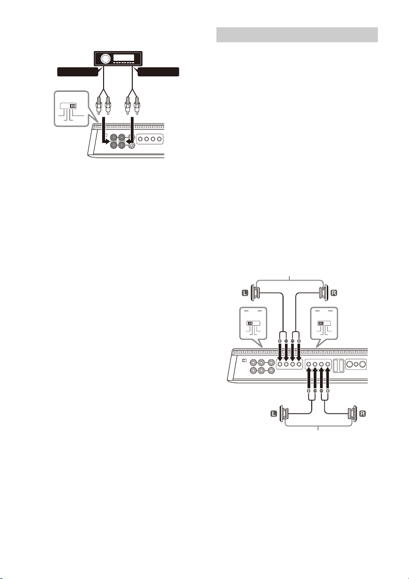
2-channel input (for bridged
connection)
With “Speaker Connection” (page 11) .
* Use a speaker wire-to-RCA adaptor (not supplied) for high-
level input connection.
Note
When making this connection, set the INPUT MODE switch
to th e “1-4” position.
4-channel input
AUDIO OUT*
2
AUDIO OUT*
1
INPUT MODE
1-4
11-2
1+3/2+4
*
3
*
3
FILTER
CH 3/4
OFF BP
HP LP
FILTER
CH 1/2
OFF BP
HP LP
CH 1/2 speaker (mi n. 2 Ω)
CH 3/4 speaker (min. 2 Ω)
With “Speaker Connection” (page 11) or .
*1 Filtered signal. Tweeter output or HPF output from the
car audio.
*2 Filtered signal. Woofer output or LPF output from the car
audio.
*3 Use a speaker wire-to-RCA adaptor (not supplied) for
high-level input connection.
Note
When making this connection, set the INPUT MODE switch
to the “1+3/2+4”.
Speaker Connection
• Be sure to use speakers with an adequate power
rating. If you use small capacity speakers, they
may be damaged.
• Do not connect any active speakers (with built-in
a
mplifiers) to the speaker terminals of the
amplifier. Doing so may damage the active
speakers.
• Use speakers with an appropriate impedance
rat
ing.
– 2 Ω to 8 Ω (stereo)
– 4 Ω to 8 Ω (bridged connection)
• Do not connect the t
erminal of the speaker
system to the car chassis, and do not connect the
terminal of the right speaker with that of the
left speaker.
Notes
• According to your needs, set the FILTER, RANGE, INPUT
SENS, etc. to the appropriate settings for CH 1/2 and CH 3/
4.
• The following is a depiction of the speaker connections
typically used to connect this amplifier. Refer to the
operating instructions supplied with your car audio and
speakers for more details about the speaker connection
for your car audio unit.
4-speaker system
With “Input Connection” (page 9) or .
Note
When making this connection, set the settings on the
control panel (top panel) to the following positions:
• For both CH 1/2 and CH 3/4:
– Set FILTER to “OFF”.
11GB

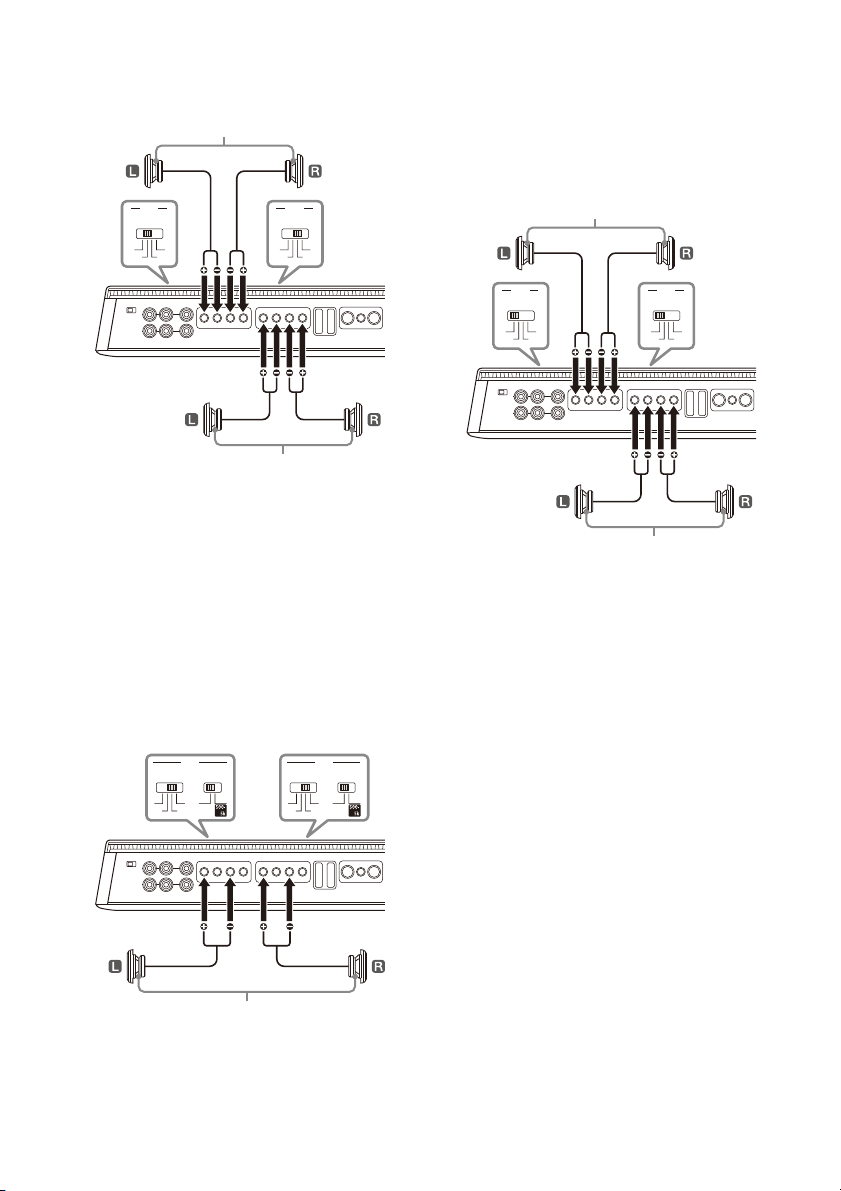
2-way system
FILTER
CH 3/4
OFF BP
HP LP
FILTER
CH 1/2
OFF BP
HP LP
Tweeter (min. 2 Ω)
Woofer (min. 2 Ω)
FILTER
CH 3/4
OFF BP
HP LP
FILTER
CH 1/2
OFF BP
HP LP
50500
RANGE (Hz)
50500
RANGE (Hz)
Subwoofer (min. 4 Ω)
FILTER
CH 3/4
OFF BP
HP LP
FILTER
CH 1/2
OFF BP
HP LP
Front speaker (min. 2 Ω)
Rear speaker (min. 2 Ω)
Additional amplifier
With “Input Connection” (page 9) , or .
Full range speaker system
With “Input Connection” (page 9) , or .
Note
When making this connection, set the settings on the
control panel (top panel) to the following positions:
•For CH 1/2:
– Set FILTER to “HP”.
– Set RANGE to “500-5k”.
•For CH 3/4:
– Set FILTER to “LP”.
– Set RANGE to “50-500” or “500-5k” depending on your
speaker specification.
2-subwoofer system (bridged
connection)
With “Input Connection” (page 9) or .
Note
When making this connection, set the settings on the
control panel (top panel) to the following positions:
• For both CH 1/2 and CH 3/4:
– Set FILTER to “LP”.
–Set RANGE to “50-500”.
Note
When making this connection, set the settings on the
control panel (top panel) to the following positions:
• For both CH 1/2 and CH 3/4:
– Set the FILTER to the “OFF”.
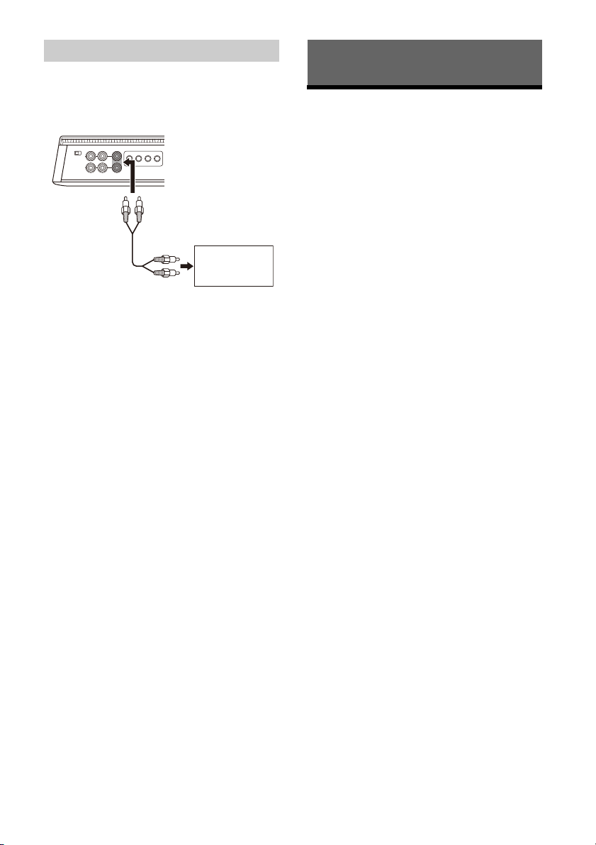
Output Connection
Through the LINE OUT connector, this amplifier can
output signals to additional amplifier. This allows a
flexible system connection that utilizes multiple
amplifiers.
Notes
• Audio signals output from LINE OUT connectors are not
affected by any signal processing, such as the HPF and LPF
settings.
• According to your needs, set the LINE OUT MODE switch
on the control panel (top panel) to “THRU”, “STEREO” or
“ALL ”.
• Refer to the operating instructions supplied with your
additional amplifier for connection details.
12GB
Additional Information
Maintenance
Precautions
• This power amplifier employs a protection circuit*
to protect the transistors and speakers if the
amplifier malfunctions. Do not attempt to test the
protection circuits by covering the heat sink or
connecting improper loads.
•If your car is parked in direct sunlight and there is
a
considerable rise in temperature inside the car,
wait until the unit cools down before use.
•For safety, keep the volume of the unit at a
m
oderate level that allows you to sufficiently hear
the sound of traffic outside the vehicle.
•Do not splash liquid onto the amplifier.
* Pro
tection circuit
This amplifier is provided with a protection circuit
t
hat operates in the following cases:
– When the unit overheats
– When a DC current is generated
– When the speaker terminals are short-circuited
The status indicator light will blink, and this unit
w
ill shut down. If this happens, stop the media
playback, turn off the connected equipment and
determine the cause of the malfunction. If this
unit has overheated, wait until it cools down
before use.
If you have any questions or problems concerning
your
unit that are not covered in this Operating
Instruction, consult your nearest Sony dealer.
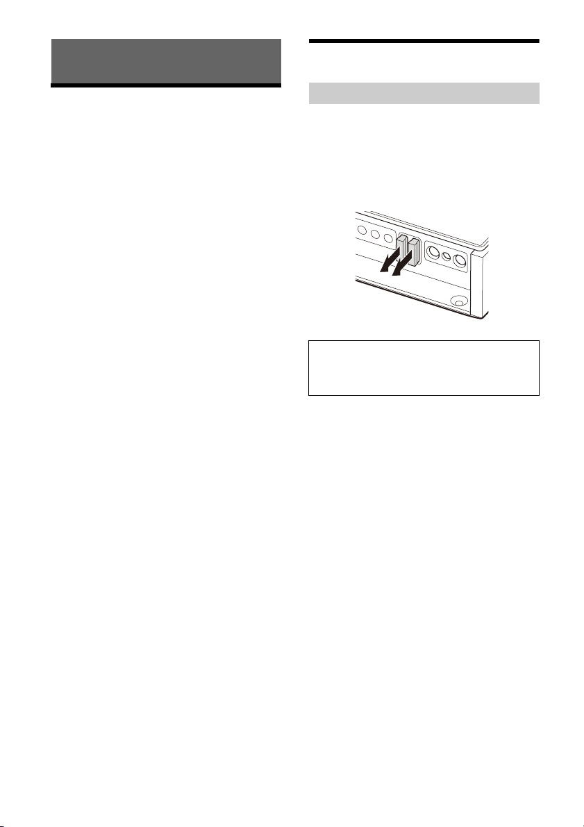
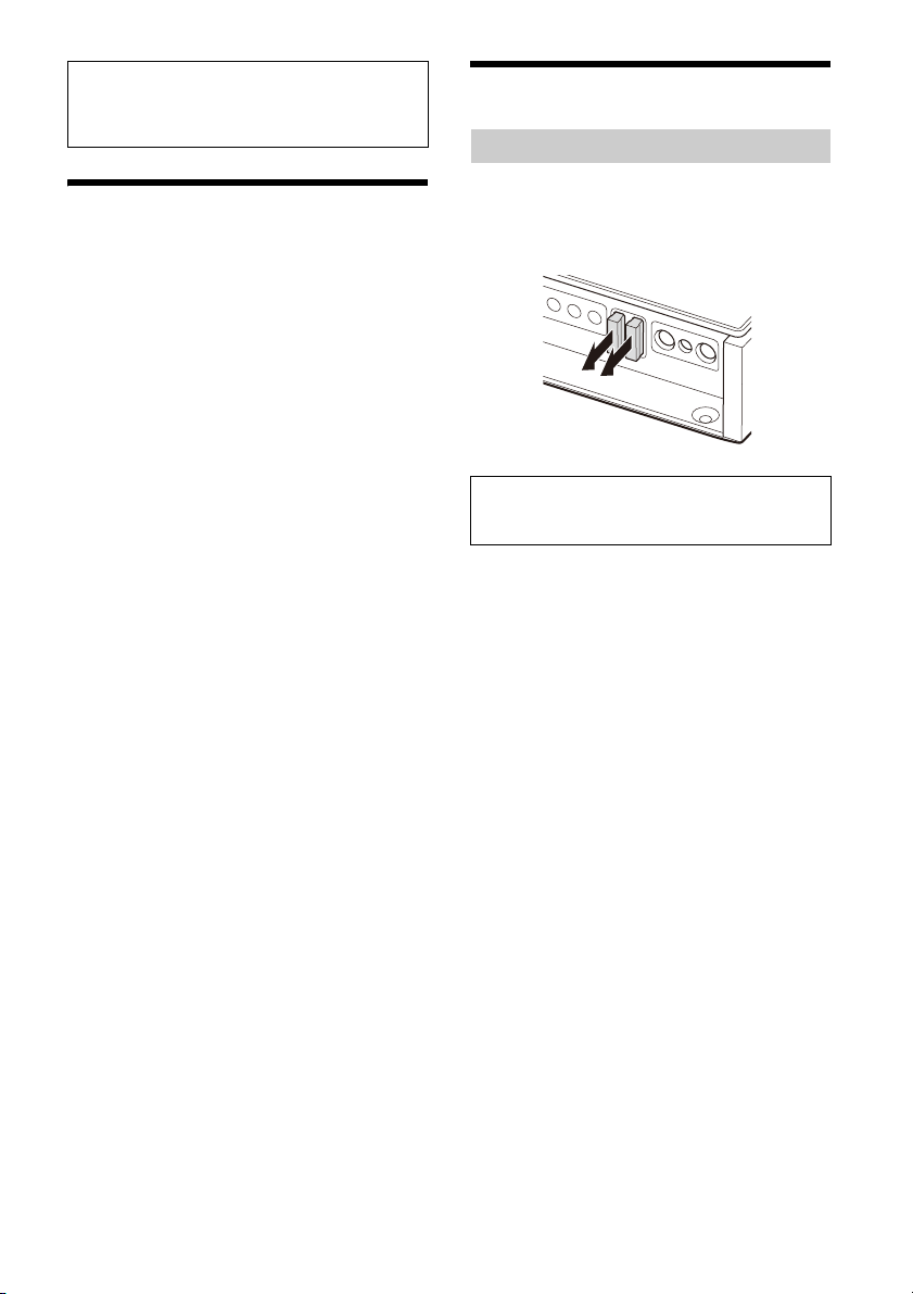
Fuse Replacement
When replacing the fuse, be sure to use one
matching the amperage rating stated on the
original fuse.
If the fuse blows, check the power connection and
r
eplace the fuse.
If the fuse blows again after replacement, there
m
ay be an internal malfunction. If this happens,
consult your nearest Sony dealer.
Warning
Never use a fuse with an amperage rating
exceeding the one supplied with the amplifier as
this could damage the amplifier.
13GB
Specifications
ɻ
ɹ
FOR THE CUSTOMERS IN THE USA.
POUR LES CLIENTS AUX ÉTATS-UNIS.
AUDIO POWER SPECIFICATIONS
CTA2006 Standard
Power Output:
100 Watts RMS × 4 Channels at 4 Ohms
an
d ≤ 1% THD+N, 165 Watts RMS × 4
Channels at 2 Ohms and ≤ 1% THD+N
Current drain:
At rated output: 30 A (4 Ω, 100 W × 4)
Remote input: 4 mA
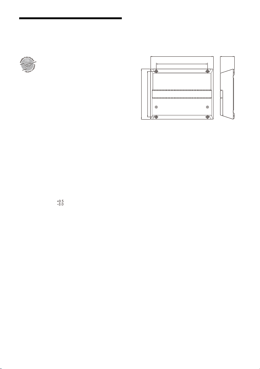
Dimensions:
Approx. 270 mm × 60 mm × 215 mm (10
3
2
/8 in × 8 1/2 in) (w/h/d)
ɸ
3
/4 in ×
ɼ
Circuit system:
Class D Technology circuit
Pulse power supply
Inputs:
RCA pin jacks
Input level adjustment range:
0.2 V – 8 V (RCA pin jacks)
3 V – 16 V (high-level input)
Outputs:
Speaker terminals
RCA pin jacks
Speaker impedance:
2 Ω – 8 Ω (stereo)
4 Ω – 8 Ω (when used as a bridging amplifier)
Maximum output:
4 Speakers: 237.5 W × 4 (at 2 Ω) / Total 950 W
Rated output (supply voltage at 14.4 V, 1 kHz, 1%
TH
D):
2 Speakers: 330 W × 2 (at 4 Ω)
4 Speakers: 165 W × 4 (at 2 Ω), 100 W × 4 (at 4 Ω)
Frequency response:
10 Hz – 40 kHz ( dB)
THD (total harmonic distortion):
0.05% or less (at 1 kHz, 4 Ω)
Low-pass filter:
50 Hz – 500 Hz, 12 dB/oct
500 Hz – 5 kHz, 12 dB/oct
High-pass filter:
50 Hz – 500 Hz, 12 dB/oct
500 Hz – 5 kHz, 12 dB/oct
Power requirements:
12 V DC car battery (negative ground (earth))
Power supply voltage:
10.5 V – 16 V
ɺ
mm (10 3/4 in)
270
220 mm
21
19
60
Mass:
Approx. 2.9 kg (6 lb 7 oz) not incl. accessories
Package contents:
Main unit (1)
Parts for installation and connection (1 set)
Design and specifications are subject to change
w
ithout notice.
(8 3/4 in)
5 mm (8 1/2 in)
6 mm (7 3/4 in)
mm (2 3/8 in)
14GB

Troubleshooting
The following checklist will assist in the correction
of most of the problems you may encounter with
your unit. Please refer to the connection and
operating procedures before going through the
checklist below.
The status indicator light does not light up.
The fuse is blown.
– Replace the fuse with a new one.
T
he ground (earth) lead is not securely
connected.
– Fasten the ground (earth) lead securely to a
me
tal point on the car chassis.
T
he voltage going into the remote input
(REMOTE) terminal is too low.
– Turn on the car audio unit if it is not turned on.
– Use a relay if the system employs too many
a
mplifiers.
Chec
k the battery voltage (10.5 V – 16 V).
The status indicator light changes from white to
red.
Turn off the amplifier. The speaker outputs have
shorted.
– Rectify the cause of the short.
T
urn off the amplifier. Make sure the speaker lead
and ground (earth) lead are securely connected.
The amplifier becomes abnormally hot.
The amplifier heats up abnormally.
– Use speakers with suitable impedance: 2 Ω –
8 Ω (stereo) or 4 Ω – 8 Ω (when used as a
br
idging amplifier).
M
ake sure to place the amplifier in a well
ventilated location.
The sound is interrupted.
The thermal protector has activated.
– Reduce the volume.
Alternator noise is heard.
The power connecting leads are installed too
close to the RCA pin cables.
– Keep the leads away from the cables.
T
he ground (earth) lead is not securely
connected.
– Fasten the ground (earth) lead securely to a
me
tal point on the car chassis.
Neg
ative speaker wires are touching the car
chassis.
– Keep the wires away from the car chassis.
The sound is muffled.
The FILTER switch is set to “HP” or “OFF”.
– When connecting the subwoofer, set to “LP”.
T
he FILTER switch is set to “LP”.
– When connecting the full range speaker, set to
“
OFF” or “HP”.
The sound is too quiet.
The INPUT SENS control setting is not
appropriate. Turn the INPUT SENS control in the
clockwise direction.
If these solutions do not help improve the situation,
c
onsult your nearest Sony dealer.
Support Site
If you have any questions for the latest support
information on this product, please visit the
website below:
Customers in the USA/Canada/Latin America:
https://www.sony.com/am/support
Customers in European countries:
https://www.sony.eu/support
Customers in other countries/regions:
https://www.sony-asia.com/support
15GB
為了確保您的安全,請務必將本裝置安裝在行李箱
座位下方。
內或
關於詳細說明,請參閱 “Installation and
Connection”(第7頁)。
使用前注意事項
•本功率放大器採用保護電路 *,在萬一放大器故障時
保護電晶體和揚聲器。請勿嘗試覆蓋散熱器或連接不
當負載以測試保護電路。
•如果
愛車停在直接日照下,而且車內溫度大幅上升,
在使用本裝置之前,請讓它冷卻。
•為安
全起見,請讓本裝置保持中等音量,以便能充分
聽到車外的交通噪聲。
•切勿
將液體濺灑在放大器上。
* 保護
電路
本放大器具備在下列狀況會操作的保護電路:
– 本
裝置過熱時
– 產
生 DC 電流時
– 揚
聲器端子短路時
狀態指示燈會閃爍,本裝置會關機。若發生這種狀
請停止播放媒體,關閉連接的設備,判斷故障
況,
的原因。若本裝置過熱,在使用前請讓它冷卻。
若您有任何關於本機的問題或困難,而本使用說明書
沒有提
及,請向您附近的 Sony 經銷商諮詢。
保養
更換保險絲
更換保險絲時,必須確保所使用的保險絲與原保險絲
的額定安培數相同。
如果保險絲燒斷,請檢查電源連接並更換保險絲。
如果保險絲更換後又被燒斷,則可能是內部故障。如
果發
生這個問題,請就近與 Sony 經銷商聯絡。
警告
絕勿使用額定安培數超過放大器隨附保險絲的保險
絲,否則可能會損壞放大器。


Pour votre sécurité, veillez à installer cet appareil
ns le coffre ou sous un siège.
da
Pour plus d’informations, reportez-vous à la
se
ction « Installation et raccordements »
(page 8).
Fabriqué en Thaïlande
La plaque signalétique reprenant la tension
d
’alimentation, etc., se trouve sur le dessous du
châssis.
La validité du libellé CE se limite uniquement aux
pa
ys où la loi l’impose, principalement les pays de
l’EEE (Espace économique européen) et la Suisse.
La validité du libellé UKCA se limite uniquement aux
pays où la loi l’impose, principalement au
Royaume-Uni.
Avis à l’attention des clients : les informations
suivantes s’appliquent uniquement aux
appareils vendus dans des pays qui
appliquent les directives de l’Union
Européenne
Ce produit a été fabriqué par ou pour le compte de
Sony Corporation.
Importateur dans l’UE : Sony Europe B.V.
Les questions basées sur la législation européenne
po
ur l’importateur ou relatives à la conformité des
produits doivent être adressées au mandataire :
Sony Belgium, bijkantoor van Sony Europe B.V., Da
Vincilaan 7-D1, 1930 Zaventem, Belgique.
Elimination des piles et
accumulateurs et des équipements
ectriques et électroniques
él
usagés (applicable dans les pays
de l’Union Européenne et dans les
autres pays disposant de systèmes
de collecte sélective)
Ce symbole apposé sur le produit, la pile ou
l’accumulateur, ou sur l’emballage, indique que le
produit et les piles et accumulateurs fournis avec ce
produit ne doivent pas être traités comme de
simples déchets ménagers. Sur certains types de
piles, ce symbole apparaît parfois combiné avec un
symbole chimique. Le symbole pour le plomb (Pb)
est rajouté lorsque ces piles contiennent plus de
0,004 % de plomb. En vous assurant que les
produits, piles et accumulateurs sont mis au rebut
de façon appropriée, vous participez activement à
la prévention des conséquences négatives que leur
mauvais traitement pourrait provoquer sur
l’environnement et sur la santé humaine. Le
recyclage des matériaux contribue par ailleurs à la
préservation des ressources naturelles. Pour les
produits qui, pour des raisons de sécurité, de
performance ou d’intégrité des données,
nécessitent une connexion permanente à une pile
ou à un accumulateur intégré(e), il conviendra de
vous rapprocher d’un Service Technique qualifié
pour effectuer son remplacement. En rapportant
votre appareil électrique, les piles et accumulateurs
en fin de vie à un point de collecte approprié vous
vous assurez que le produit, la pile ou
l’accumulateur intégré sera traité correctement.
Pour tous les autres cas de figure et afin d’enlever
l
es piles ou accumulateurs en toute sécurité de
votre appareil, reportez-vous au manuel
d’utilisation. Rapportez les piles et accumulateurs,
et les équipements électriques et électroniques
usagés au point de collecte approprié pour le
recyclage. Pour toute information complémentaire
au sujet du recyclage de ce produit ou des piles et
accumulateurs, vous pouvez contacter votre
municipalité, votre déchetterie locale ou le point de
vente où vous avez acheté ce produit.
Si vous avez des questions concernant cet appareil
ou
si vous rencontrez des problèmes qui ne sont
pas abordés dans ce mode d’emploi, contactez
votre revendeur Sony le plus proche.
2FR

Caractéristiques
•Puissance de sortie nominale de 100 W (à 4 Ω) et
165 W (à 2 Ω).
•Technologie de classe D*
•Pour les autoradios ne comportant pas une sortie
de ligne, un raccordement direct (raccordement
d’entrée haut niveau) avec la sortie haut-parleur
de votre autoradio est possible en utilisant un
adaptateur fil haut-parleur vers RCA (non fourni).
•Une fonction de mise sous tension par détection
de
haut niveau permet à cet appareil d’être activé
sans un raccordement à REMOTE.
•Filtres HP (passe-haut), LP (passe-bas) et BP
(
passe-bande) pour les canaux avant et arrière.
•Circuit et indicateur de protection fournis.
• Alimentation électrique par impulsions*
puissance de sortie stable et régulée.
*1 Technologie de classe D
La technologie de classe D est une méthode permettant
de convertir et d’amplifier des signaux musicaux grâce à
des transistors MOSFET pour obtenir des signaux par
impulsion à grande vitesse. De plus, elle est caractérisée
par une efficacité de haut niveau et un faible
dégagement de chaleur.
*2 Alimentation électrique par impulsions
Cet appareil est équipé d’un régulateur de puissance
intégré qui convertit la pui ssance fournie par une batterie
de voiture de 12 V CC en impulsions ultrarapides au
moyen d’un commutateur à semi-conducteur. Ces
impulsions sont amplifiées par le transformateur
d’impulsions intégré et séparées en alimentations
positive et négative avant d’être reconverties en courant
continu. Ce processus permet de compenser les
fluctuations de tension provenant de la batterie de
voiture. Ce système d’alimentation léger assure une
alimentation électrique très efficace avec une sortie
d’impédance faible.
1
2
pour une
3FR

Table des matières
Caractéristiques. . . . . . . . . . . . . . . . . . . . . . . . . . . . . 3
Emplacement des commandes
Amplificateur de puissance . . . . . . . . . . . . . . . . . . . 5
Installation et raccordements
Pièces destinées à l’installation et aux
raccordements. . . . . . . . . . . . . . . . . . . . . . . . . . . 8
Installation . . . . . . . . . . . . . . . . . . . . . . . . . . . . . . . . . 8
Raccordement . . . . . . . . . . . . . . . . . . . . . . . . . . . . . . 9
Informations complémentaires
Précautions . . . . . . . . . . . . . . . . . . . . . . . . . . . . . . . 14
Entretien. . . . . . . . . . . . . . . . . . . . . . . . . . . . . . . . . . 15
Spécifications . . . . . . . . . . . . . . . . . . . . . . . . . . . . . 15
Dépannage . . . . . . . . . . . . . . . . . . . . . . . . . . . . . . . 16
Site d’assistance . . . . . . . . . . . . . . . . . . . . . . . . . . . 17
4FR
Emplacement des commandes
TURN-ON
REMOTE SIGNAL
INPUT MODE
1-4
11-2
1+3/2+4
FILTER
CH 1/2
BRIDGED
OFF BP
HP LP
CH 1 CH 2
LINE OUT MODE
THRU ALL
STEREO
INPUT SENS
FILTER
CH 3/4
OFF BP
HP LP
INPUT SENS
BRIDGED
CH 3 CH 4
L R L R
REMOTE+12 V
GROUND
TURN-ON
REMOTE SIGNAL
INPUT MODE
1-4
11-2
1+3/2+4
FILTER
CH 1/2
BRIDGED
OFF BP
HP LP
CH 1 CH 2
LINE OUT MODE
THRU ALL
STEREO
INPUT SENS
50500
FILTER RANGE (Hz)
CH 3/4
HPF (Hz)
OFF BP
HP LP
500-
5k
500
150
50050
1.5k
LPF (Hz)
500
150
50050
5k
1.5k
INPUT SENS
BRIDGED
CH 3 CH 4
L R L R
REMOTE
+
12 V
GROUND
5k
50500
RANGE (Hz) HPF (Hz)
500-
5k
500
150
50050
1.5k
LPF (Hz)
500
150
50050
5k
1.5k
5k
50500
RANGE (Hz) HPF (Hz)
500-
5k
500
150
50050
1.5k
LPF (Hz)
500
150
50050
5k
1.5k
5k
50500
RANGE (Hz) HPF (Hz)
500-
5k
500
150
50050
1.5k
LPF (Hz)
500
150
50050
5k
1.5k
5k
ȫ Ȭ ȭ Ȯ ȯ Ȱ ȱ Ȳ Ȯ ȯ Ȱ ȱ Ȳ
Ȫ
ȳ ȴ
ȩ
INPUT 1 CH 1
INPUT 2 CH 2
INPUT 3 CH 3
INPUT 4 CH 4
Amplificateur de puissance
Panneau de commande (panneau supérieur)
Capot du dissipateur thermique
L’orientation du capot du dissipateur thermique
p
eut être modifiée selon votre préférence
(page 8).
In
S’allume en blanc en cours de fonctionnement.
Lorsque le circuit de protection s’active,
l
’indicateur d’état lumineux passe du blanc au
dicateur d’état lumineux
rouge. Pour plus d’informations, reportez-vous à
la section « Dépannage » (pa ge 16).
C
ommutateur TURN-ON
Permet de sélectionner le mode de mise sous
t
ension de l’amplificateur.
•« REMOTE » : sélectionnez cette option pour
a
ctiver le mode de mise sous tension à
distance. L’amplificateur est mis sous tension
lorsqu’un signal de mise sous tension est reçu
de la borne REMOTE. Reportez-vous à la
section « Borne REMOTE » (page 10) pour plus
d’informations.
•« SIGNAL » : sélectionnez cette option pour
ac
tiver le mode de mise sous tension par
détection de haut niveau. L’amplificateur est
mis sous tension lorsqu’un signal de mise
sous tension est reçu du connecteur INPUT.
Cette fonctionnalité est uniquement
disponible pour un raccordement des entrées
(niveau des haut-parleurs) haut niveau.
Reportez-vous à la section « Borne REMOTE »
(page 10) pour plus d’informations.
C
ommutateur INPUT MODE
Permet de sélectionner le mode d’entrée.
•« 1-4 » : pour une entrée stéréo à 4 canaux.
5FR

•« 1 » : pour une entrée stéréo à 1 canal.
INPUT 1 CH 1
CH 2
CH 3
CH 4
INPUT 1 CH 1
CH 3
INPUT 2 CH 2
CH 4
INPUT 1 CH 1
INPUT 3 CH 3
INPUT 2 CH 2
INPUT 4 CH 4
INPUT 1 LINE OUT 1
INPUT 2 LINE OUT 2
INPUT 1 LINE OUT 1
INPUT 3
INPUT 2 LINE OUT 2
INPUT 4
INPUT 1
INPUT 2 LINE OUT 1
INPUT 3 LINE OUT 2
INPUT 4
•« 1-2 » : pour une entrée stéréo à 2 canaux.
•« 1+3/2+4 » : pour une entrée à 4 canaux.
ommutateur LINE OUT MODE
C
Permet de définir le mode de sortie des signaux
s
ur les connecteurs LINE OUT 1 et 2. Les sorties
des signaux des connecteurs LINE OUT ne sont
pas filtrées et ne sont pas affectées par les
réglages FILTER.
•« THRU » : sortie stéréo (mode through)
•« STEREO » : sortie stéréo (mode sommation)
•« ALL » : sortie mono (mode sommation)
C
ommande HPF (filtre passe-haut)
Selon les réglages RANGE, ajustez la fréquence
d
e coupure dans la gamme 50 Hz – 500 Hz ou
50
0 Hz – 5 kHz.
C
ommande LPF (filtre passe-bas)
Selon les réglages RANGE, ajustez la fréquence
d
e coupure dans la gamme 50 Hz – 500 Hz ou
50
0 Hz – 5 kHz.
C
ommande INPUT SENS (sensibilité d’entrée)
Permet de régler le niveau de la sensibilité
d
’entrée pour CH 1/2 et CH 3/4. Tournez le
bouton dans le sens des aiguilles d’une montre
lorsque le niveau de sortie des appareils audio
connectés est faible.
Bo
rnier à vis SPEAKER OUT
Bo
rnier à vis +12 V
Bornier à vis REMOTE
Bornier à vis GROUND
C
ommutateur FILTER
Permet de régler le mode de filtre pour CH 1/2 et
CH
3/4.
•« OFF » : permet de désactiver le filtre.
•« HP » (passe-haut) : les fréquences
i
nférieures au réglage de la commande HPF
sont filtrées.
•« LP » (passe-bas) : les fréquences
s
upérieures au réglage de la commande LPF
sont filtrées.
•« BP » (passe-bande) : la gamme de
f
réquences pour la commande HPF est
automatiquement fixée sur 50 Hz – 500 Hz ;
l
a gamme de fréquences pour la commande
LPF est automatiquement fixée à 500 Hz –
5 kHz. Les fréquences en dehors des réglages
d
es gammes HPF et LPF sont filtrées.
C
ommutateur RANGE
Permet de régler la plage de fréquences pour les
c
ommandes HPF (filtre passe-haut) et LPF (filtre
passe-bas).
•« 50-500 » : plage de fréquence du caisson
de
graves.
•« 500-5k » : plage de fréquences du hautpa
rleur médium ou du tweeter.
6FR
Panneau des connecteurs (panneau avant)
13
L
REMOTE
+
12 V
GROUND
40 A 40 A
INPUT
VOLTAGE
LOW HIG H
INPUT SPEAKER OUTLINE OUT
CH 1
CH 2
1
24 2
R
BRIDGED
L R
CH 3 CH 4
BRIDGED
L R
ȵ ȶ ȷ ȸ ȹȺ
Commutateur INPUT VOLTAGE
Permet de sélectionner le type de raccordement
d
es entrées.
•« LOW » : sélectionnez cette option pour le
r
accordement d’entrées bas niveau (niveau
ligne) à l’aide de rallonges RCA (non fournies).
•« HIGH » : sélectionnez cette option pour le
r
accordement d’entrées haut niveau (niveau
haut-parleurs) à l’aide d’un adaptateur fil
haut-parleur vers RCA (non fourni).
C
onnecteur INPUT
Pour plus d’informations concernant le
ra
ccordement, reportez-vous à la section
« Raccordement des entrées » (pag e 10).
onnecteur LINE OUT
C
Pour plus d’informations concernant le
r
accordement, reportez-vous à la section
« Raccordement des sorties » (pa ge 14).
Bo
rne SPEAKER OUT
Pour plus d’informations concernant le
r
accordement, reportez-vous à la section
« Raccordement des haut-parleurs » (page 12).
Fu
sible (40 A)
Bo
rne +12 V
Borne REMOTE
Borne GROUND
7FR
Installation et raccordements
Pièces destinées à l’installation
et aux raccordements
V is de montage
(5 × 20 mm) (4)
Clé hexagonale (2,5 mm) (1)
Cette liste des pièces ne comprend pas tout le
contenu de l’emballage.
Installation
Installation de l’amplificateur
•Installez l’amplificateur dans le coffre ou sous un
siège.
•Pour votre sécurité, choisissez un emplacement
d
e montage qui n’entrave pas la conduite.
• N’installez pas l’amplificateur à proximité du
c
hauffage, dans des zones exposées à la lumière
directe du soleil ou dans des endroits exposés à
de fortes températures.
•N’installez pas l’amplificateur sous un tapis de sol
o
ù la dissipation thermique de l’amplificateur ne
pourrait pas se faire correctement.
•Évitez d’installer l’amplificateur dans des zones
e
xposées à la pluie, à l’humidité, à la poussière et
aux salissures.
Montage de l’amplificateur
Placez l’amplificateur à l’endroit où vous
1
souhaitez l’installer, puis marquez les
emplacements des 4 trous de vis sur la
pl
aque de montage (non fournie).
2 Percez ensuite un trou pilote de 3 mm au
niveau de chaque repère et fixez
l’amplificateur sur la plaque avec les vis de
montage .
La longueur des vis de montage est de
20 mm ; assurez-vous que l’épaisseur de la
p
laque de montage est supérieure à 20 mm.
Modification de l’orientation du capot du
dissipateur thermique
L’orientation du capot du dissipateur thermique
peut être modifiée selon votre préférence.
1 Faites glisser le capot vers l’avant, puis
soulevez-le pour le retirer.
2 Faites tourner le capot dans le sens
souhaité.
3 Alignez le capot sur les ergots situés sur
l’amplificateur, puis remettez le capot en
place en le faisant glisser jusqu’à ce que
vous entendiez un clic.
8FR
Raccordement
REMOTE
OUT*
1
+12 V REMOTE
GROUND
Fusible (80 A)
à un point
métallique du
châssis du
véhicule
inférieur à 450 mm
•Avant d’effectuer les raccordements, débranchez
la borne de la masse de la batterie du véhicule
afin d’éviter les courts-circuits. Raccordez cet
amplificateur au fil d’alimentation +12 V
u
niquement après avoir raccordé tous les autres
fils.
•Cet amplificateur est conçu pour fonctionner sur
un c
ourant de 12 V CC avec masse négative
uni
quement.
• Ne faites pas fonctionner l’amplificateur lorsque la
ba
tterie est faible, car l’alimentation de
l’amplificateur doit être suffisante pour obtenir
des performances optimales.
•Si votre véhicule est équipé d’un ordinateur de
b
ord, intégrant par exemple un système de
navigation, le fait de débrancher la borne de
masse de la batterie du véhicule peut
endommager la mémoire de l’ordinateur. Laissez
le fil de masse branché et raccordez cet
amplificateur au fil d’alimentation +12 V
u
niquement après avoir raccordé tous les autres
fils afin d’éviter les courts-circuits.
•Lorsque raccordez et installez les câbles d’entrée
et
de sortie, éloignez-les du fil
d’alimentation +12 V. Il existe un risque
d’
interférences sonores lorsqu’ils sont trop
proches les uns des autres.
Remarques concernant les raccordements
•Pour effectuer les raccordements aux bornes du
panneau des connecteurs et pour effectuer les
différents réglages, retirez le capot supérieur afin
d’accéder au panneau de commande (panneau
supérieur).
• Lorsque vous resserrez les vis, veillez à ne pas trop
fo
rcer, car cela pourrait endommager les bornes
ou les câbles.
+
12 V
REMOTE
GROUND
+
12 V
REMOTE
GROUND
Raccordements électriques
*1 Si vous disposez de l’autoradio d’origine ou d’un autre
autoradio dépourvu de sortie de commande à distance
pour l’amplificateur, raccordez la borne d’entrée de
commande à distance (REMOTE) à l’alimentation ACC.
Avec un raccordement des entrées haut niveau,
l’amplificateur peut également être activé sans qu’un
raccordement REMOTE soit nécessaire. Néanmoins, cette
fonction n’est pas garantie pour tous les autoradios.
*2 Masse au châssis du véhicule.
Borne +12 V
• Raccordez le fil d’alimentation +12 V à la borne
+12 V uniquement après avoir raccordé tous les
au
tres fils.
• Utilisez un fil d’alimentation +12 V équipé d’un
fu
sible 80 A.
• Lorsque l’amplificateur fonctionne à pleine
p
uissance, un courant de plus de 80 A circule à
t
ravers le système. Par conséquent, veillez à ce
que les fils à raccorder à la borne +12 V soient au
m
oins de calibre 4 (AWG-4) ou aient une section
s
upérieure à 22,0 mm².
• Tous les fils d’alimentation raccordés à la borne
p
ositive de la batterie doivent être équipés d’un
fusible à une distance inférieure à 450 mm de la
b
orne de la batterie avant de traverser quelque
partie métallique que ce soit.
• Veillez à ce que les fils raccordant la batterie du
v
éhicule au point métallique sur le châssis du
véhicule soient d’un calibre au moins égal à celui
du fil d’alimentation +12 V raccordé depuis la
b
atterie à l’amplificateur.
9FR
• Veillez à ce que les fils raccordant la batterie du
INPUT
VOLTAGE
LOW HIGH
*
INPUT
VOLTAGE
LOW HIGH
*
Sortie hautparleur (gauche)
Sortie hautparleur (droit)
véhicule au point métallique sur le châssis du
véhicule soient d’un calibre inférieur ou égal à 0
(AWG-1/0) ou aient une section de 55 mm² et au
m
oins un calibre égal à celui du fil d’alimentation
+12 V raccordé depuis la batterie à l’amplificateur.
Borne GROUND
•Veillez à raccorder le fil de masse correctement à
un point métallique sur le châssis du véhicule. Un
raccordement trop lâche peut entraîner un
mauvais fonctionnement de l’amplificateur.
•Lorsque l’amplificateur fonctionne à pleine
pui
ssance, un courant de plus de 80 A circule à
ravers le système. Par conséquent, veillez à ce
t
que les fils à raccorder à la borne GROUND soient
au moins de calibre 4 (AWG-4) ou aient une
se
ction supérieure à 22,0 mm².
Borne REMOTE
• Pour mettre l’amplificateur sous tension à l’aide
du fil de mise sous tension à distance dédié,
réglez le commutateur TURN-ON sur « REMOTE »,
p
uis raccordez la sortie de commande à distance
(REMOTE OUT) de votre autoradio à la borne
REMOTE.
•Lorsque vous utilisez un autoradio dépourvu de
sor
tie de commande à distance (REMOTE OUT)
pour l’amplificateur, raccordez la borne REMOTE à
l’alimentation ACC de votre véhicule ou à défaut,
utilisez le réglage de mise sous tension par
détection d’un signal.
• Utilisez un fil de mise sous tension à distance dont
l
e calibre varie entre AWG-8 et AWG-18 ou ayant
une section comprise entre 8,4 mm² et 0,82 mm².
Remarques concernant l’utilisation du
réglage de mise sous tension par détection
de haut niveau
•Avec un raccordement des entrées haut niveau,
l’amplificateur peut également être activé sans
qu’un raccordement REMOTE soit nécessaire.
Néanmoins, cette fonction n’est pas garantie pour
tous les autoradios.
•En réglant le commutateur TURN-ON sur
« SIGNAL », l’amplificateur se met en marche
a
utomatiquement lorsqu’un signal de mise sous
tension est reçu de la borne INPUT.
Raccordement des entrées
Le connecteur INPUT peut être utilisé tant par une
ent
rée bas niveau que par une entrée haut niveau.
Raccordement des entrées bas niveau
Réglez le commutateur INPUT VOLTAGE sur « LOW »
et raccordez le câble RCA (non fourni) de l’autoradio
de votre véhicule au connecteur INPUT.
* Câble RCA (non fourni)
Raccordement des entrées haut niveau
Réglez le commutateur INPUT VOLTAGE sur
« HIGH » et utilisez un adaptateur fil haut-parleur
v
ers RCA (non fourni) pour raccorder le fil du hautparleur de l’autoradio de votre véhicule au
connecteur INPUT.
10FR
* Adaptateur fil haut-parleur vers RCA (non fourni)
Vous trouverez ci-après une description du
FRONT
AUDIO OUT
REAR
AUDIO OUT
INPUT MODE
1-4
11-2
1+3/2+4
**
AUDIO OUT
INPUT MODE
1-4
11-2
1+3/2+4
*
AUDIO OUT
INPUT MODE
1-4
11-2
1+3/2+4
*
AUDIO OUT
INPUT MODE
1-4
11-2
1+3/2+4
*
raccordement et des réglages habituellement
utilisés lors du raccordement d’un autoradio et de
cet amplificateur. Consultez le mode d’emploi
fourni avec votre autoradio pour obtenir plus
d’informations concernant le raccordement des
entrées correspondant à votre autoradio.
Entrée à 4 canaux
Avec « Raccordement des haut-parleurs » (p age 12)
.
* Utilisez un adaptateur fil haut-parleur vers RCA (non fourni)
pour le raccordement des entrées haut niveau.
Remarque
Lorsque vous effectuez ce raccordement, réglez le
commutateur INPUT MODE sur la position « 1-4 ».
Entrée à 1 canal
Avec « Raccordement des haut-parleurs » (p age 12)
ou .
Entrée à 2 canaux
Avec « Raccordement des haut-parleurs » (page 12)
.
* Utilisez un adaptateur fil haut-parleur vers RCA (non fourni)
pour le raccordement des entrées haut niveau.
Remarque
Lorsque vous effectuez ce raccordement, réglez le
commutateur INPUT MODE sur la position « 1-2 ».
Entrée à 2 canaux (pour un
raccordement en pont)
Avec « Raccordement des haut-parleurs » (page 12)
.
* Utilisez un adaptateur fil haut-parleur vers RCA (non fourni)
pour le raccordement des entrées haut niveau.
Remarque
Lorsque vous effectuez ce raccordement, réglez le
commutateur INPUT MODE sur la position « 1 ».
* Utilisez un adaptateur fil haut-parleur vers RCA (non fourni)
pour le raccordement des entrées haut niveau.
Remarque
Lorsque vous effectuez ce raccordement, réglez le
commutateur INPUT MODE sur la position « 1-4 ».
11FR
Entrée à 4 canaux
AUDIO OUT*
2
AUDIO OUT*
1
INPUT MODE
1-4
11-2
1+3/2+4
*
3
*
3
FILTER
CH 3/4
OFF BP
HP LP
FILTER
CH 1/2
OFF BP
HP LP
Haut-parleur CH 1/2 (2 Ω min.)
Haut-parleur CH 3/4 (2 Ω min.)
Avec « Raccordement des haut-parleurs » (p age 12)
ou .
*1 Signal filtré. Sortie du tweeter ou sortie HPF depuis
l’autoradio.
*2 Signal filtré. Sortie du caisson de graves ou sortie LPF
depuis l’autoradio.
*3 Utilisez un adaptateur fil haut-parleur vers RCA (non
four
ni) pour le raccordement des entrées haut niveau.
Remarque
Lorsque vous effectuez ce raccordement, réglez le
commutateur INPUT MODE sur « 1+3/2+4 ».
Raccordement des haut-parleurs
•Veillez à utiliser des haut-parleurs dont la
puissance nominale est adaptée. Si vous utilisez
des haut-parleurs de faible capacité, ils risquent
d’être endommagés.
•Ne raccordez aucun haut-parleur actif (doté d’un
a
mplificateur intégré) aux bornes des hautparleurs de l’amplificateur. Cela pourrait
endommager les haut-parleurs actifs.
•Utilisez des haut-parleurs dont l’impédance
nomina
le est adaptée.
–2 Ω à 8 Ω (stéréo)
–4 Ω à 8 Ω (raccordement en pont)
•Ne raccordez pas la borne d
u système de haut-
parleurs au châssis du véhicule, et ne raccordez
pas la borne du haut-parleur droit avec celle du
haut-parleur gauche.
Remarques
• Selon vos besoins, choisissez les réglages FILTER, RANGE,
INPUT SENS etc., adaptés pour CH 1/2 et CH 3/4.
• Vous trouverez ci-après une description des
r
accordements des haut-parleurs habituellement utilisés
pour raccorder cet amplificateur. Consultez le mode
d’emploi fourni avec votre autoradio et vos haut-parleurs
pour obtenir plus d’informations concernant le
raccordement des haut-parleurs correspondant à votre
autoradio.
Système à 4 haut-parleurs
Avec « Raccordement des entrées » (page 10) ou
.
12FR
Remarque
Lorsque vous effectuez ce raccordement, choisissez les
positions de réglage du panneau de commande (panneau
supérieur) suivantes :
• Pour CH 1/2 et CH 3/4 :
– Réglez FILTER sur « OFF ».
Système à 2 voies
FILTER
CH 3/4
OFF BP
HP LP
FILTER
CH 1/2
OFF BP
HP LP
Tweeter (2 Ω min.)
Caisson de graves (2 Ω min.)
FILTER
CH 3/4
OFF BP
HP LP
FILTER
CH 1/2
OFF BP
HP LP
50500
RANGE (Hz)
50500
RANGE (Hz)
Caisson de graves (4 Ω min.)
FILTER
CH 3/4
OFF BP
HP LP
FILTER
CH 1/2
OFF BP
HP LP
Haut-parleur avant (2 Ω min.)
Haut-parleur arrière (2 Ω min.)
Avec « Raccordement des entrées » (page 10) ,
ou .
Remarque
Lorsque vous effectuez ce raccordement, choisissez les
positions de réglage du panneau de commande (panneau
supérieur) suivantes :
•Pour CH 1/2 :
– Réglez FILTER sur « HP ».
– Réglez RANGE sur « 500-5k ».
•Pour CH 3/4 :
– Réglez FILTER sur « LP ».
– Réglez RANGE sur « 50-500 » ou « 500-5k » selon les
caractéristiques de votre haut-parleur.
Système comportant 2 caissons de
graves (raccordement en pont)
Avec « Raccordement des entrées » (page 10) ou
.
• Pour CH 1/2 et CH 3/4 :
– Réglez FILTER sur « LP ».
– Réglez RANGE sur « 50-500 ».
Système de haut-parleurs pleine
gamme
Avec « Raccordement des entrées » (page 10) ,
ou .
Remarque
Lorsque vous effectuez ce raccordement, choisissez les
positions de réglage du panneau de commande (panneau
supérieur) suivantes :
• Pour CH 1/2 et CH 3/4 :
– Réglez FILTER sur « OFF ».
Remarque
Lorsque vous effectuez ce raccordement, choisissez les
positions de réglage du panneau de commande (panneau
supérieur) suivantes :
13FR
Raccordement des sorties
Amplificateur
supplémentaire
Cet amplificateur peut transmettre des signaux à
des amplificateurs supplémentaires par
l’intermédiaire du connecteur LINE OUT. Cela
permet un raccordement flexible du système qui
utilise plusieurs amplificateurs.
Remarques
• Les signaux audio transmis à partir des connecteurs LINE
OUT ne sont pas affectés par un traitement de signal, quel
qu’il soit, notamment les réglages HPF et LPF.
• Selon vos besoins, réglez le commutateur LINE OUT MODE
sur le panneau de commande (panneau supérieur) sur
« THRU », « STEREO » ou « ALL ».
• Consultez le mode d’emploi fourni avec votre amplificateur
supplémentaire pour plus d’informations concernant les
raccordements.
Informations complémentaires
Précautions
•Cet amplificateur de puissance est équipé d’un
circuit de protection* conçu pour protéger les
transistors et les haut-parleurs en cas de
défaillance de l’amplificateur. N’essayez pas de
tester l’efficacité du circuit de protection en
recouvrant le dissipateur thermique ou en
effectuant des raccordements inadéquats.
•Si votre véhicule est garé en plein soleil, et si la
t
empérature augmente considérablement à
l’intérieur, attendez que l’appareil refroidisse
avant de l’utiliser.
• Pour votre sécurité, maintenez le volume de
l
’appareil à un niveau modéré qui vous permet
d’entendre suffisamment le bruit de la circulation
à l’extérieur du véhicule.
•Ne renversez pas de liquide sur l’amplificateur.
* Ci
rcuit de protection
Cet amplificateur est fourni avec un circuit de
p
rotection qui entre en fonction dans les cas
suivants :
– Lorsque l’appareil est en surchauffe.
– Lorsqu’un courant continu est généré.
– Lorsque les bornes des haut-parleurs sont court-
c
ircuitées.
L’indicateur d’état lumineux se met alors à
c
lignoter et l’appareil s’éteint. Si cela se produit,
arrêtez la lecture multimédia, éteignez
l’équipement raccordé et déterminez l’origine du
problème. Si cet appareil est en surchauffe,
attendez qu’il refroidisse avant de l’utiliser.
Si vous avez des questions concernant cet appareil
ou
si vous rencontrez des problèmes qui ne sont
pas abordés dans ce mode d’emploi, contactez
votre revendeur Sony le plus proche.
14FR
 Loading...