

Sony XC-555P User Manual
A-B3C-100-11 (1)
CCD Color
Video Camera Module
Technical Manual
XC-555/555P
2002 Sony Corporation

Table of Contents
Overview
RS-232C Command List
Main Features ............................................................ 3
Connection Diagram ................................................. 4
Location of Parts and Operation.............................. 5
Mode Setting .............................................................. 6
Installation ................................................................. 7
Connections............................................................... 9
Genlock ...................................................................... 9
Functions That can be Controlled via the RS-232C
Interface ................................................................. 10
Precautions to be Observed When Using RS-232C
Commands ............................................................ 11
Setting the RS-232C Switches ............................... 11
Connections............................................................. 12
Communication Specifications .............................. 12
The Sequence from “Power up” to Beginning/
End of Communication......................................... 13
Camera Function Setting Commands ................... 14
Setting Gain.............................................................. 14
Shutter Settings ........................................................ 14
White Balance Settings ............................................ 15
Video Process Setting .............................................. 16
System Settings ....................................................... 16
Camera Setup Readout from a List ......................... 17
Examples.................................................................. 18
RS-232C Mode and the Memory Banks ................. 19
Structure of the Memory Banks................................ 19
Functions Available with Memory Load/Save ........... 20
The Memory Bank to be Activated When Power is
Turned on .............................................................. 20
Appendix
Shutter Speed and the Settings Command .......... 21
Specifications .......................................................... 25
Dimensions .............................................................. 26
Spectral Sensitivity Characteristics
(Typical Value) ....................................................... 27
XC-555 ..................................................................... 27
XC-555P ................................................................... 27
2

Overview
Overview
The XC-555/555P is an ultra-small color camera
module that utilizes a 1/2- type Charge Coupled
Device.
Main Features
Ultra-small size and lightweight
The camera is so small and light that you can install it
anywhere: even in locations where conventional video
cameras cannot be installed.
High resolution
A built-in Super HAD (Hole Accumulated Diode)
sensor, allows high sensitivity, low smear images. You
can shoot, even under poor lighting conditions.
Electronic shutter with a wide range of
operating speeds
Using the electronic shutter DIP switches, these levels
of shutter speed (OFF, 1/1000, and FLICKERLESS)
are available to allow you to match the shutter speed to
the shooting conditions.
When you set the DIP switches for the CCD IRIS
function, the shutter speed is adjusted automatically,
based on the amount of light allowed to enter, ensuring
the most appropriate level of image signal.
High sensitivity
With a CCD offering 380,000 effective pixels, highresolution images can be obtained.
Four white balance adjustment modes
Using the white balance DIP switches, you can choose
from among four white balance modes (3200K/5600K/
ATW/MAN) to choose the best settings for shooting
conditions, and the most appropriate color
compensation.
3
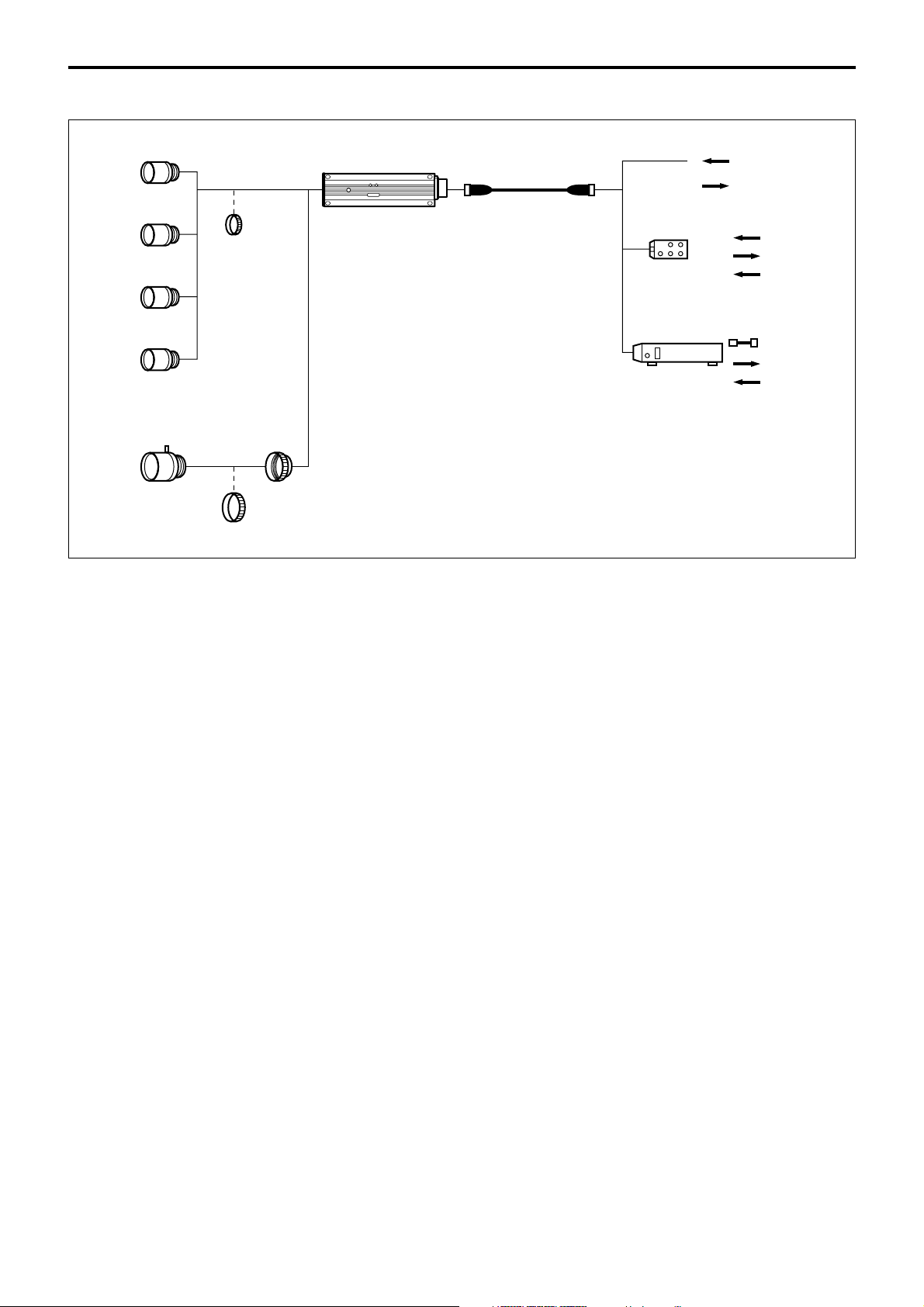
Connection Diagram
Overview
NF mount lens
VCL-03S12XM
VCL-06S12XM
VCL-12S12XM
VCL-12SXM (***)
C mount lens (Manual iris)
LO-999ERK
(C-mount adaptor)
LO-77ERK
(Macro ring kit)
LO-999CMT
(*****)
12P 12P
CCXC12P02N
05N
10N
25N
JB-77
DC-700
DC12 V
(#Pin#2&G)
VIDEO
BNC
BNC
DC12 V
VIDEO
HD/VD
AC
VIDEO
HD/VD
4
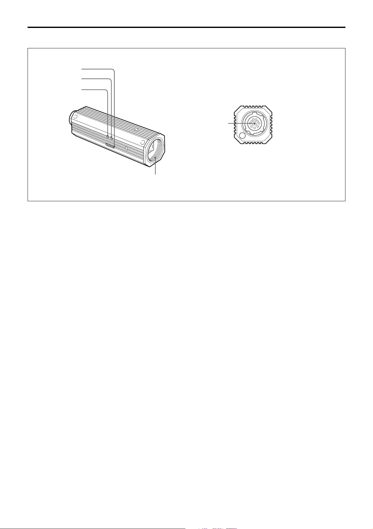
Location of Parts and Operation
1
2
3
5
4
Overview
1 Dip switches for setting functions
This switches are used to adjust white balance and
shutter speed; and to flip AGC (ON/OFF) and output
signals (Y/C/VBS).
For details, see “Mode Setting” on page 6.
2 R control for manual white balance adjustment
This control is effective when the white balance
switches are set to MAN. Adjust the red color by
turning the control.
3 B control for manual white balance adjustment
This control is effective when the white balance
switches are set to MAN. Adjust the blue color by
turning the control.
4 Lens mount (special mount)
5 DC IN/SYNC/VIDEO connector (multi 12-pin)
This connector inputs DC 12V power and outputs the
video signal when the CCXC-12P02N/12P05N/
12P10N/12P25N camera cable is connected.
If the unit is connected to devices that originate a
synchronized signal, the external synchronous signal
(VS, HD/VD) can be used to move the color camera
module.
5
Overview
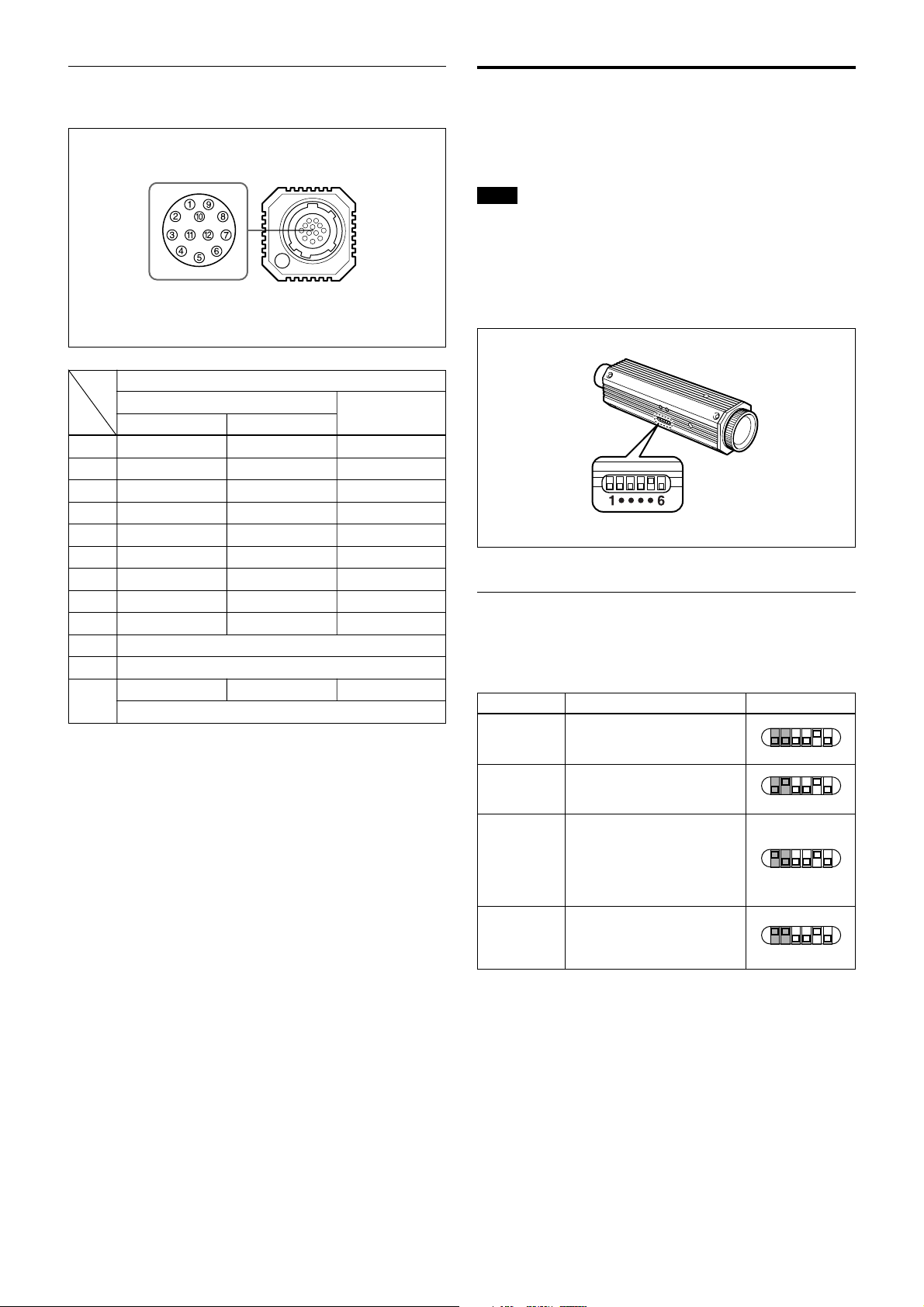
Pin assignment of the DC IN/SYNC/VIDEO
connector
Signal
External Sync signal
Pin No.
1 GND (Earth) GND (Earth) GND (Earth)
2 +12V +12V +12V
3
4
5 HD Input (Earth) - 6 HD Input (signal) - 7 VD Input (signal) VS Input (signal) 8 GND (–/C) GND (–/C) GND (–/C)
9 –/C Output (signal) –/C Output (signal) –/C Output (signal)
10 RS-232C (TXD) *
11 RS-232C (RXD) *
12 VD Input (Earth) VS Input (Earth) GND
HD,VD VS Input
VBS/Y Output (Earth) VBS/Y Output (Earth) VBS/Y Output (Earth)
VBS/Y Output (signal) VBS/Y Output (signal) VBS/Y Output (signal)
Sync signal types
Internal Sync
signal
RS-232C (Earth)
Mode Setting
By flipping the DIP switches located on the side of this
camera, you can adjust the following functions.
Note
Each switch is assigned to the function. The switches
that should be set for a certain function (white balance,
shutter speed, AGC (Auto Gain Control), switching of
output signals(Y/C/VBS)) are specified. The effective
switches are indicated by shade in the illustrations.
To Adjust the white balance
Select the white balance setting according to the
lighting conditions.
Lighting condition DIP switch setting
3200K
(fixed)
5600K
(fixed)
ATW
(auto tracing
white balance)
MAN
(manual)
For indoor shooting under
incandescent light (factory
setting).
For outdoor shooting on sunny
days.
The white balance is adjusted
according to the color
temperature transition of the
subject. This mode is suitable
for shooting with variable
lighting.
Select this position when you
want to adjust the red color
with the R control and the blue
color with the B control.
1 ····6
1 ····6
1 ····6
1 ····6
6
Overview
To adjust the shutter speed
Set the shutter speed switches to select the desired
shutter speed.
Using the CCD IRIS function, set the CCD IRIS mode.
Shutter speed DIP switch setting
OFF
1/1000
CCD IRIS
FLICKERLESS
1/60 sec. (factory setting)
(XC-555)
1/50 sec. (factory setting)
(XC-555P)
1/1000 sec.
Set the CCD IRIS mode.
1/100 sec. (XC-555)
1/120 sec. (XC-555P)
1 ····6
1 ····6
1 ····6
1 ····6
AGC (Auto Gain Control) ON/OFF
Gain DIP switch setting
ON
OFF
Auto gain control
(factory setting)
0 dB
1 ····6
1 ····6
Y/C/VBS
Select the camera output signal.
Output signal DIP switch setting
Y/C
VBS
Select this position to output
the Y/C separated signal from
the DC IN/VIDEO connector.
Select this position to output
the VBS signal from the DC IN/
VIDEO (factory setting).
1 ····6
1 ····6
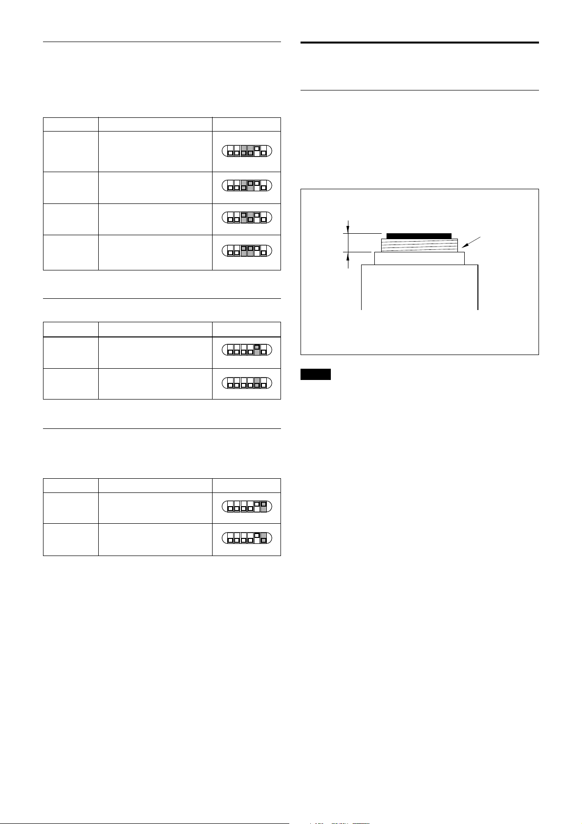
Installation
Usable Lenses
• VCL-12S12XM NF mount lens (f=12mm)
• VCL-06S12XM NF mount lens (f=6mm)
• VCL-03S12XM NF mount lens (f=3.5mm)
• VCL-12SXM NF mount lens (f=12mm)
• C-mount lens for 1/2-inch CCD.
Lens mount shoulder
4.1 mm
or less
Notes
• To attach a C-mount type lens, the C-mount adaptor
(LO-999CMT) is required.
• This camera uses a 1/2-inch CCD. So the lens should
be used with this size of CCD. If used with a lens
intended for 2/3-inch CCD, the angle of view will be
different.
• When connecting a heavy lens, make sure that it is
supported properly.
• When connecting heavy lens, make sure that it is not
subject to shocks or vibration.
7
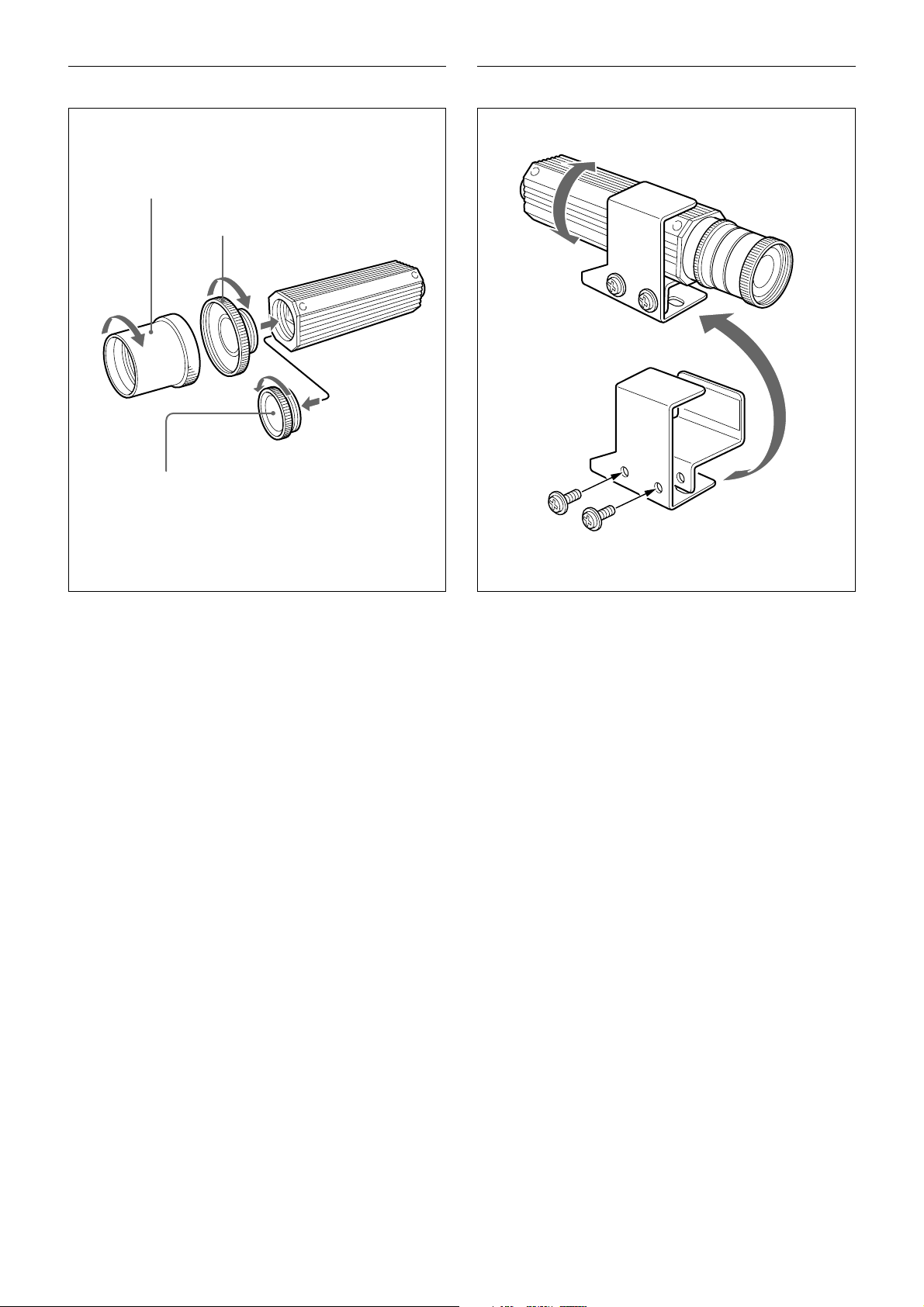
To attach a lens To install the camera on a tripod
3
2
Overview
1
1 Remove the lens mount cap by turning it
counterclockwise.
2 Screw the C-mount adaptor (LO-999CMT) into the
lens mount of the camera. (only when using a Cmount lens)
3 Screw the lens.
When you have finished installation,
tighten the screws to secure the module.
When mounting the camera on a tripod, use the
supplied tripod adaptor.
1 Assemble the tripod adaptor parts.
2 Mount the video camera module on the tripod
adaptor.
8
Overview
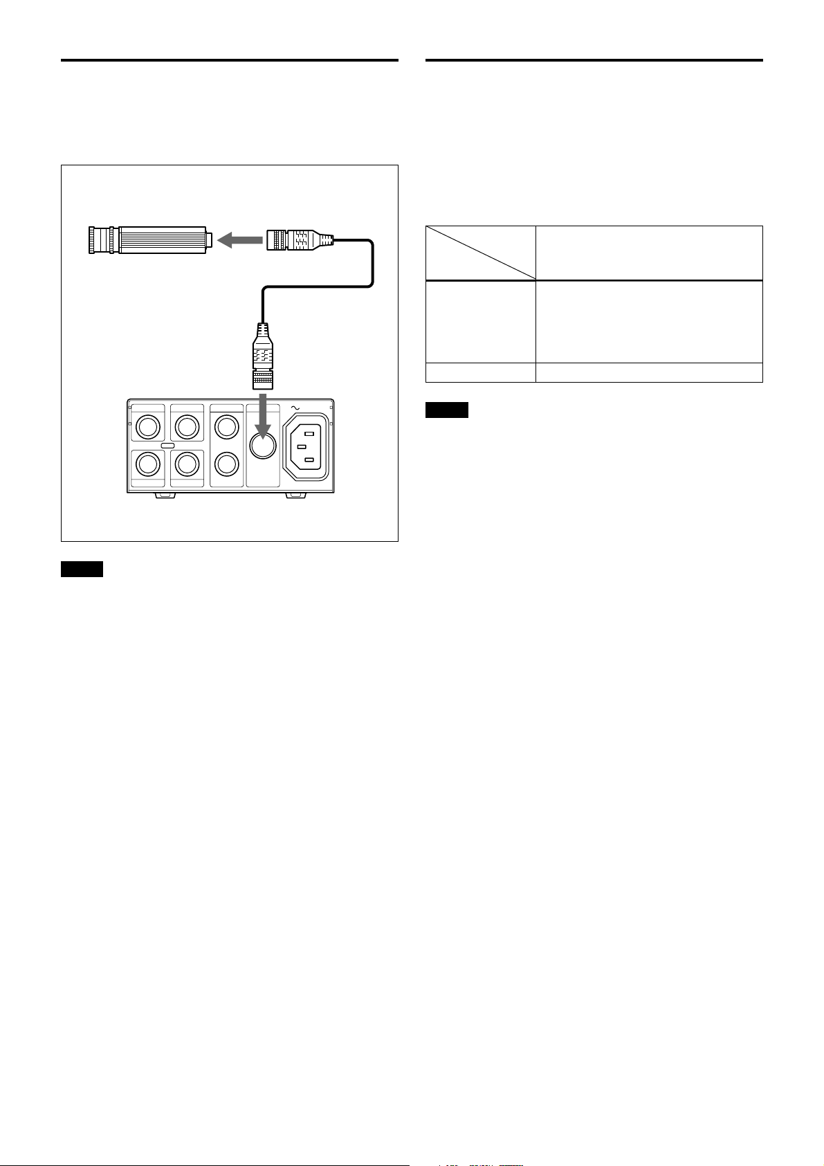
Connections
An example of the assembly of the DC700/DC700CE
Camera Adaptor.
Color video camera module
to DC/IN/SYNC/VIDEO connector
CCXC-12P02N/12P05N/
12P10N/12P25N
DC-700
WEN
122
TRIGHDVD/SYNC
CAMERAVIDEO
1
AC IN
Genlock
The color video camera module is designed so that
internal sync and external sync are switched
automatically. When the color video camera module
receives the following external sync signal, the camera
is synchronized to that external sync signal.
Input signal
HD/VD, VS
Output signal
VBS out
Y/C out
Notes
• Use a synchronous signal specified by this Technical
Manual. For details on the specifications, see page
25.
• You cannot input a VBS signal to the camera as a
synchronous signal.
The Signal is horizontally synchronized with
an HD signal externally input and is vertically
synchronized with an VD signal externally
input.
The burst signal is not externally
synchronized.
Same as above
Notes
• Make sure to turn off the power to the units you are
connecting or their components may be damaged.
• When disconnecting the cord, pull it out by the plug.
Never pull the cord itself.
• Connect the power cord after completing all other
connections.
9
 Loading...