

Page 1
Integrated AV
Amplifier
3-856-168-11(1)
Operating instructions
Mode d’emploi
Manual de Instrucciones
Manual de Instruçõnes
EN
F
E
P
TA-VE700
© 1996 by Sony Corporation
Page 2

WARNING
To prevent fire or shock
hazard, do not expose
the unit to rain or
moisture.
To avoid electrical shock, do not open
the cabinet. Refer servicing to qualified
personnel only.
Do not install the appliance in a
confined space, such as a bookcase or
build-in cabinet.
Precautions
On safety
• Should any solid object or liquid fall
into the cabinet, unplug the amplifier
and have it checked by qualified
personnel before operating it any
further.
On power sources
• Before operating the amplifier, check
that the operating voltage is identical
with your local power supply. The
operating voltage is indicated on the
nameplate at the rear of the amplifier.
• The unit is not disconnected from the
AC power source (mains) as long as it
is connected to the wall outlet, even if
the unit itself has been turned off.
• If you are not going to use the
amplifier for a long time, be sure to
disconnect the amplifier from the
wall outlet. To disconnect the mains
lead, grasp the plug itself; never pull
the cord.
• AC power cord must be changed only
at the qualified service shop.
• The mains switch is located on the
front exterior.
If you have any question or problem
concerning your amplifier, please
consult your nearest Sony dealer.
On placement
• Place the amplifier in a location with
adequate ventilation to prevent heat
build-up and prolong the life of the
amplifier.
• Do not place the amplifier near heat
sources, or in a place subject to direct
sunlight, excessive dust or
mechanical shock.
• Do not place anything on top of the
cabinet that might block the
ventilation holes and cause
malfunctions.
On operation
• Before connecting other components,
be sure to turn off and unplug the
amplifier.
On cleaning
• Clean the cabinet, panel and controls
with a soft cloth slightly moistened
with a mild detergent solution. Do
not use any type of abrasive pad,
scouring powder or solvent such as
alcohol or benzine.
EN
2
Page 3
About This Manual
The instructions in this manual describe
the controls on the amplifier. You can
also use the controls on the remote if
they have the same or similar names as
those on the amplifier.
• The “Remote Button Descriptions”
section on page 21 provides an
overview of the remote buttons.
• The following icons are used in this
manual:
Indicates that you can use only
the remote to do the task.
Indicates hints and tips for
making the task easier.
This amplifier incorporates the Dolby
Pro Logic Surround system.
Manufactured under license from Dolby
Laboratories Licensing Corporation.
DOLBY, the double-D symbol a and
“PRO LOGIC” are trademarks of Dolby
Laboratories Licensing Corporation.
TABLE OF CONTENTS
Getting Started
Unpacking 4
Hookup Overview 4
Audio Component Hookups 5
Speaker System Hookups 5
TV/VCR Hookups 6
AC Hookups 7
Before You Use Your Amplifier 7
Amplifier Operations
Selecting a Component 8
Indexing Programme source 9
Recording 10
Using the Sleep Timer 10
Using Sound Fields
Using Pre-programmed Sound Fields 11
Taking Advantage of the Sound Fields 12
Customizing Sound Fields 12
Getting the Most Out of Dolby Pro Logic Surround Sound 13
EN
Advanced Remote Operations
Operating One Component While Using Another
(background operation) 15
Changing the Factory Setting of a FUNCTION Button 15
Programming the Remote 16
Additional Information
Troubleshooting 17
Specifications 18
Glossary 18
Rear Panel Descriptions 20
Remote Button Descriptions 21
Index 22
EN
3
Page 4
Getting Started
Unpacking
Check that you received the following items with the
amplifier:
• Remote commander (remote) (1)
• Size AA (R6) batteries (2)
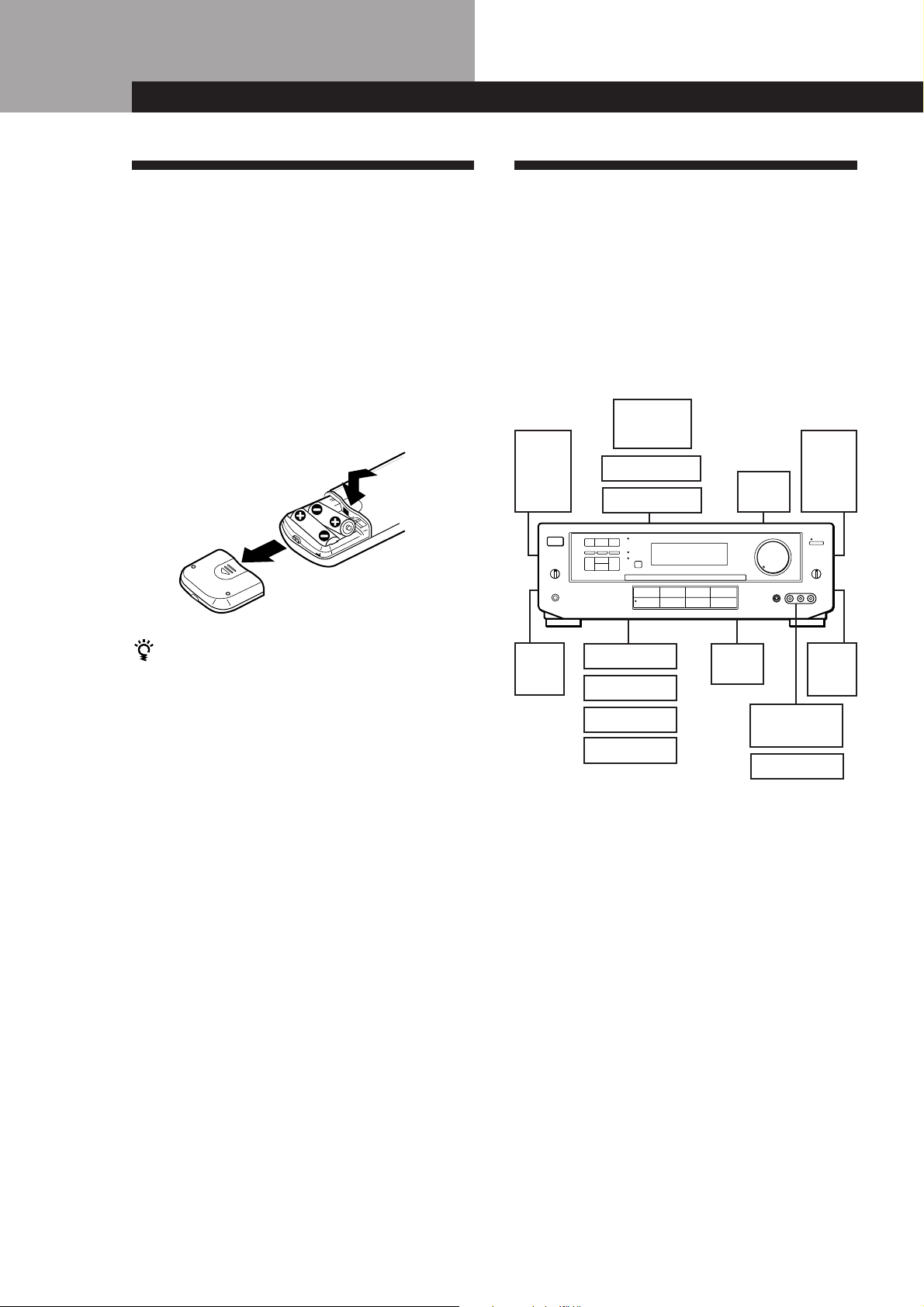
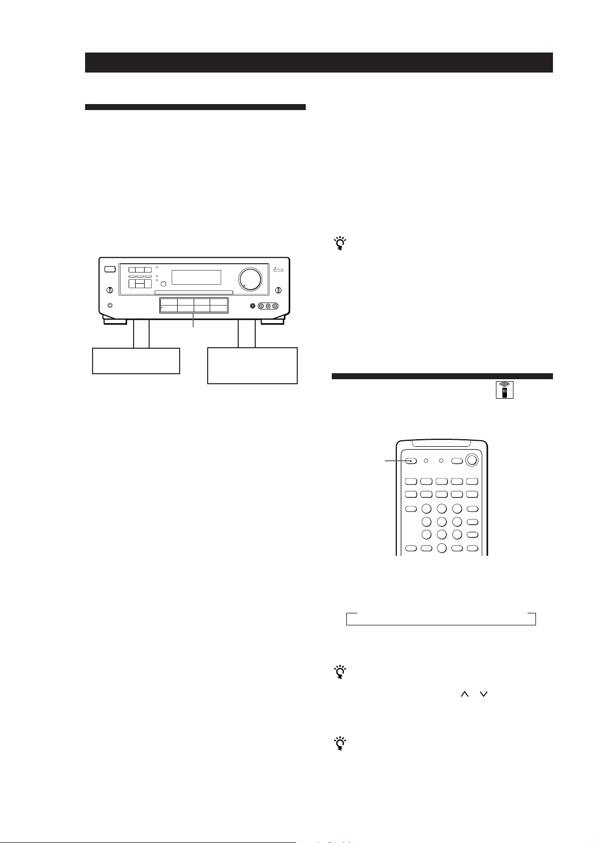
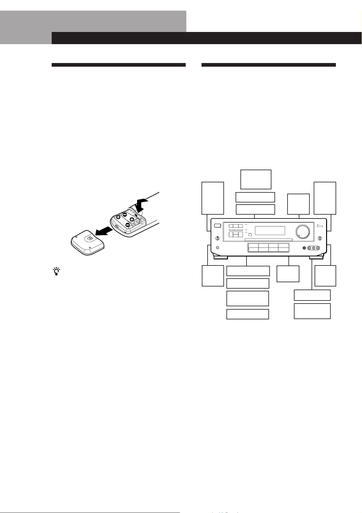
Inserting batteries into the remote
Insert two size AA (R6) batteries with the + and – on
the battery compartment. When using the remote,
point it at the remote sensor g on the amplifier.
Hookup Overview
The amplifier allows you to connect and control the
following audio/video components. Follow the
hookup procedures for the components that you want
to connect to the amplifier on the pages specified. To
learn the locations and names of each jacks, see “Rear
Panel Descriptions” on page 20.
Speaker
System
Hookups (5, 6)
Front
speaker
(L)
TV/VCR Hookups (6, 7)
TV
VCR
LD player
Active
woofer
Front
speaker
(R)
When to replace batteries
Under normal use, the batteries should last for about 6
months. When the remote no longer operates the
amplifier, replace both batteries with new ones.
Notes
• Do not leave the remote in an extremely hot or humid
place.
• Do not use a new battery with an old one.
• Do not expose the remote sensor to direct sunlight or
lighting apparatuses. Doing so may cause a malfunction.
• If you don’t use the remote for an extended period of time,
remove the batteries to avoid possible damage from
battery leakage and corrosion.
Rear
speaker
(L)
CD player
Tuner
Tape/MD deck
Turntable
Audio Component
Hookups (5)
Centre
speaker
Video camera
Video game
TV/VCR Hookups
(6, 7)
Rear
speaker
(R)
recorder
Before you get started
• Turn off the power to all components before making
any connections.
• Do not connect the mains leads until all of the
connections are completed.
• Be sure to make connections firmly to avoid hum
and noise.
• When connecting an audio/video cable, be sure to
match the color-coded pins to the appropriate jacks
on the components: Yellow (video) to Yellow; White
(left, audio) to White; and Red (right, audio) to Red.
EN
4
Page 5
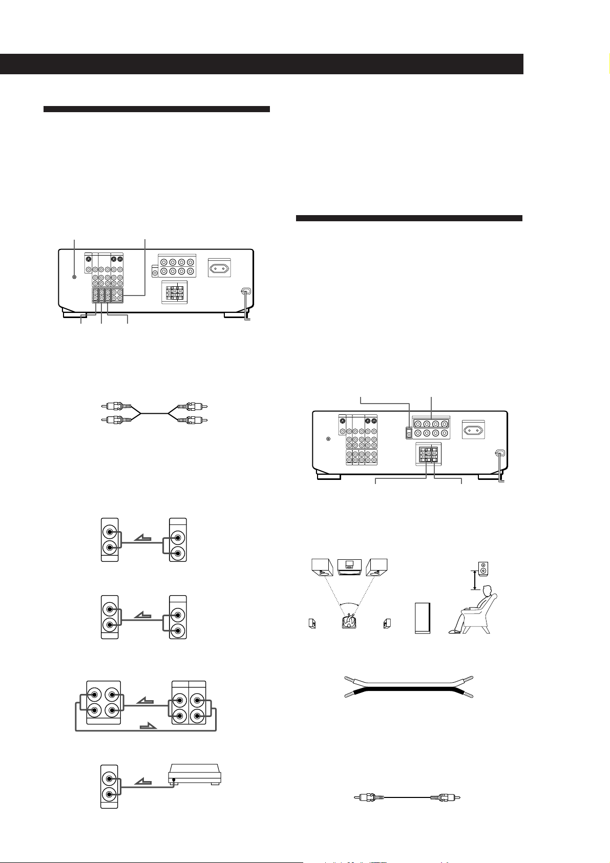
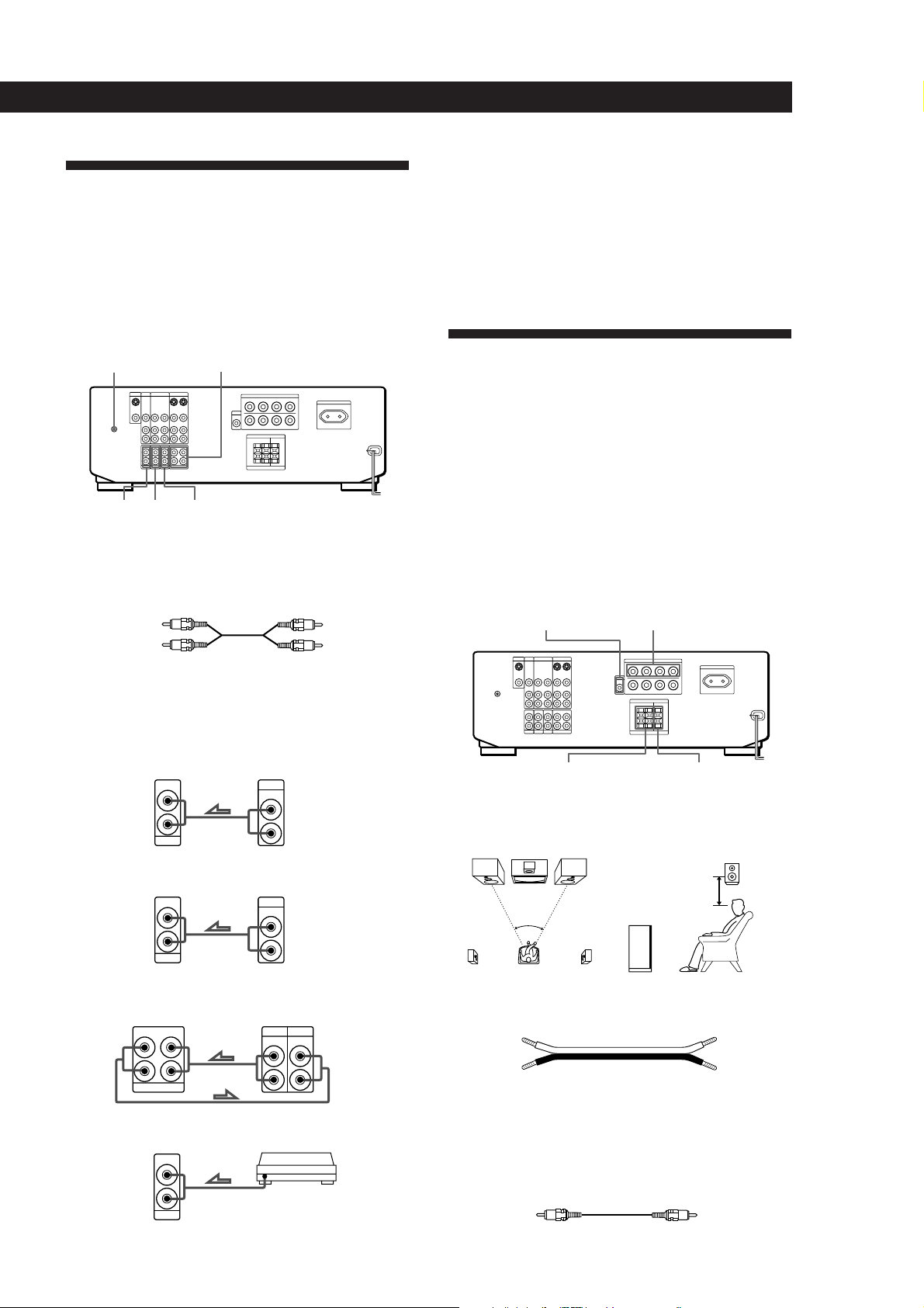
Audio Component Hookups
Getting Started
• If your turntable has an earth lead
To prevent hum, connect the earth lead to the y ground
terminal on the amplifier.
Overview
This section describes how to connect your audio
components to the amplifier.
For specific locations of the jacks, see the illustration
below.
y
TUNERPHONO
What cords will I need?
Audio cords (not supplied) (1 for each CD player and Tuner
(turntable, if necessary); 2 for tape deck, or MD deck)
TAPE/MD
CD
White (L)White (L)
Red (R)Red (R)
Where do I go next?
Go on to the next section to connect the speakers.
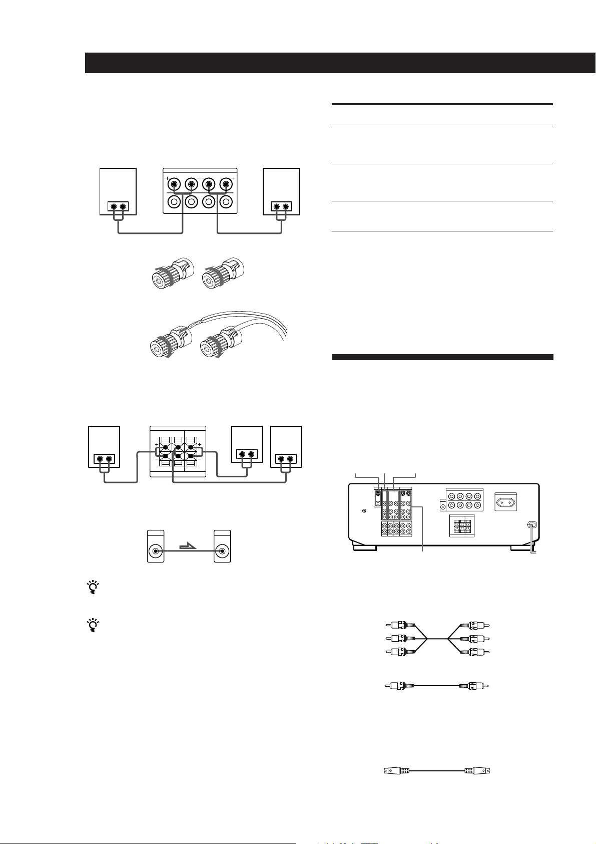
Speaker System Hookups
Overview
This section describes how to connect your speakers to
the amplifier. Although front (left and right) speakers
are required, centre, rear speakers, and active woofer
are optional. Adding centre and rear speakers will
enhance the surround effects. Connecting an active
woofer will increase bass response.
For specific locations of the terminals, see the
illustration below.
MIX AUDIO OUT FRONT SPEAKERS A
Hookups
The arrow ç indicates signal flow.
CD player
Tuner
Tape/MD deck
L
R
Turntable
Amplifier
IN
L
R
CD
IN
L
R
TUNER
INREC OUT
TAPE/MD
Amplifier
IN
L
R
PHONO
CD player
OUTPUT
LINE
TunerAmplifier
OUTPUT
LINE
TAPE/MDAmplifier
OUTPUT
Turntable
SURROUND
SPEAKERS REAR
L
R
For optimum surround sound effect, place your
speakers as shown below.
SURROUND
SPEAKERS CENTER
Rear speaker
60 - 90 cm
45°
L
R
Front speaker
What cords will I need?
• Speaker cord (not supplied) (1 for each speaker)
INPUT
LINELINE
(+)
L
R
Twist the stripped ends of the cord about 15 mm (2/3 inch).
(–)
Be sure to match the speaker cord to the appropriate
terminal on the components: + to + and – to –. If the cords
are reversed, the sound will be distorted and will lack bass.
• Monaural audio cord (not supplied) (1 for an active
woofer)
Black Black
(+)
(–)
(continued)
EN
5
Page 6
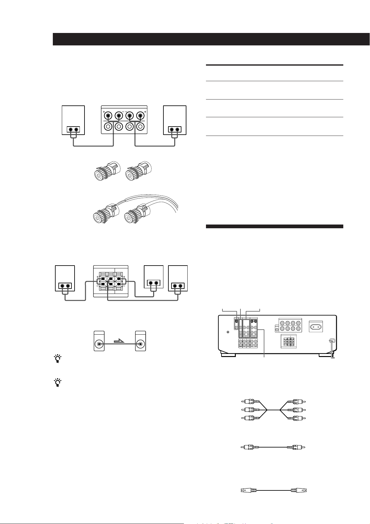
Getting Started
Hookups
Front speakers
Front speaker
(R)
A
} ]
To connect the speaker cords
R
Amplifier
FRONT SPEAKERS
IMPEDANCE USE 4-16 Ω
]}
Front speaker
A
L
≥
]}
Rear and centre speakers
Rear speaker
(R)
Amplifier
SURROUND SPEAKERS
REAR LR CENTER
Centre speaker
} ]} ]
LR
8-16Ω IMPEDANCE USE 4-16Ω Ω
Rear speaker
} ]
(L)
} ]
(L)
To drive
Speaker system A (connected
Set SPEAKERS selector to
A
to the FRONT SPEAKERS A
terminals)
Speaker system B (connected
B
to the FRONT SPEAKERS B
terminals)
Both speaker systems A and
A+B*
B (parallel connection)
*Do not use A+B with SOUND FIELD set to ON.
Where do I go next?
To complete your system, go to “AC Hookups” on page 7. If
you want to connect video components to enjoy surround
sound when watching TV programmes or video tapes, go on
to the next section.
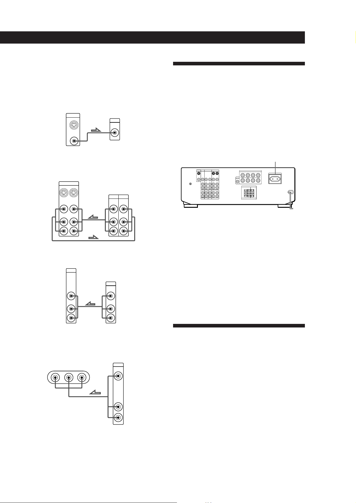
TV/VCR Hookups
Overview
This section describes how to connect video
components to the amplifier. For specific locations of
the jacks, see the illustration below.
MONITOR
VIDEO 2TV/LD
Active woofer
Amplifier Active woofer
MIX
AUDIO
OUT
INPUT
VIDEO 1
If you have an additional front speaker system
Connect them to the FRONT SPEAKERS B terminals.
What cables will I need?
• Audio/video cable (not supplied) (1 for TV or LD player;
2 for each VCR)
If your TV monitor uses separate speakers
You can connect one of them to the SURROUND
SPEAKERS CENTER terminals for use with Dolby Pro
Logic Surround Sound (see page 13).
Yellow
White (L)
Red (R)
Yellow
White (L)
Red (R)
• Video cable (not supplied) (1 for a TV monitor)
Yellow
Yellow
Selecting the speaker system
If you connect only one set of front speakers, set the
SPEAKERS selector on the front panel to A. If you
connect two sets of front speakers, see the following:
EN
6
If you want to watch higher quality video images
You can use an S-VIDEO cable (not supplied).
• S-VIDEO cable (not supplied)
Page 7
Hookups
The arrow ç indicates signal flow.
TV monitor
If you use a TV monitor, do not connect anything to the TV/
LD VIDEO IN jack.
Amplifier
MONITOR
OUT
VIDEO
OUT
VCR (via the VIDEO 1 jacks)
If you have two VCRs, connect the second one to the VIDEO
2 jacks.
Amplifier
VIDEO 1
IN
OUT
VIDEO
VIDEO
IN
OUT
AUDIO
AUDIO
IN
OUT
L
R
TV or LD player (via the TV/LD jacks)
Amplifier
TV/LD
VIDEO
IN
AUDIO
IN
L
R
TV monitor
INPUT
VIDEO
VCR
OUTPUT
INPUT
VIDEO VIDEO
AUDIO AUDIO
TV or LD player
OUTPUT
VIDEO
AUDIO
L
R
L
R
Getting Started
AC Hookups
Connecting the mains lead
Connect the mains lead from this amplifier and from
your audio/video components to a wall outlet.
If you connect other audio components to the
SWITCHED AC OUTLET on the amplifier, the
amplifier can supply power to the connected
component so you can turn on/off whole system when
you turn on/off the amplifier.
SWITCHED AC OUTLET
/
to a wall outlet
Caution
Make sure that the power consumption of the component
connected to the amplifier’s AC outlet does not exceed 100
watts. Do not connect high-wattage electrical home
appliances such as electric irons, fans, or TVs to this outlet.
Where do I go next?
Before you use the␣ amplifier, go to the next section to make
sure that all the controls are set to the appropriate positions.
Video camera recorder/Video game
Use the VIDEO 3 INPUT jacks on the front panel.
Video camera recorder
or video gameAmplifier
VIDEO 3 INPUT
VIDEO L – AUDIO – R
OUTPUT
VIDEO
AUDIO
L
R
Where do I go next?
Go on to the next section to connect the mains lead and
complete your home theater system.
Before You Use Your Amplifier
Before you start using your amplifier, make sure that
you have:
• Turned MASTER VOLUME to the leftmost
position (0).
• Selected the appropriate speaker system. (For
details, see “Selecting the speaker system” on
page 6)
• Set BALANCE to the centre position.
Turn on the amplifier and check the following
indicator.
• Press MUTING on the remote if MUTING appears
in the display.
EN
7
Page 8
Amplifier Operations
Amplifier Operations
Selecting a Component
To listen to or watch a connected component, first
select the function on the amplifier or with the remote.
Before you begin, make sure you have:
• Connected all components securely and correctly as
indicated on pages 4 to 7.
• Turned MASTER VOLUME to the leftmost position
(0) to avoid damaging your speakers.
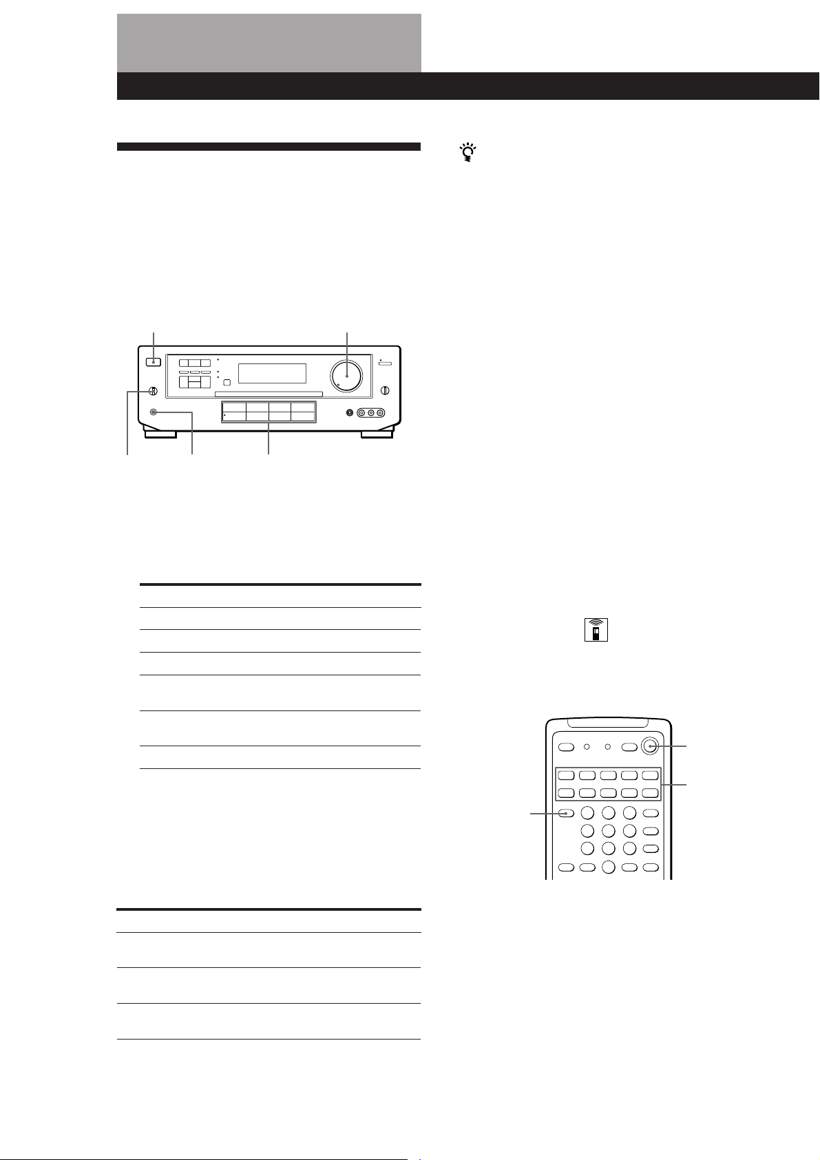
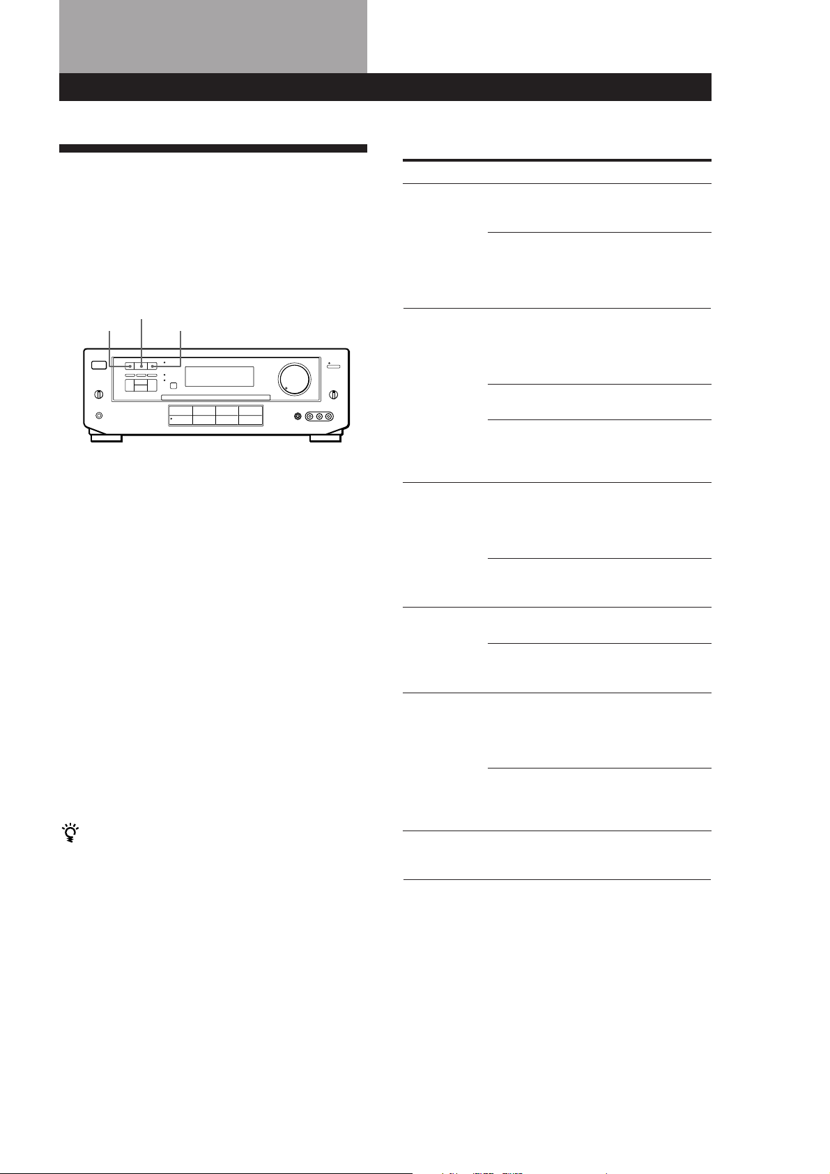
POWER
1 Press POWER to turn on the amplifier.
2 Press a function button to select the component
you want to use:
To listen to or watch Press
Records PHONO
Radio programmes TUNER
Compact Discs (CD) CD
Audio tapes TAPE/MD
or MiniDiscs (MD)
Video tapes, etc. VIDEO 1, VIDEO 2,
TV programmes␣ or laser discs TV/LD
MASTER VOLUME
Function buttonsPHONESSPEAKERS
or VIDEO 3
When you listen with headphones
Connect the headphones to the PHONES jack and set
the SPEAKERS selector to OFF.
Watching video programmes
When you watch TV or video programmes, we
recommend you play audio portion through the
amplifier instead of your TV’s speaker. This lets you
take advantage of the amplifier’s surround sound
effects, like Dolby Surround, and lets you use the
amplifier’s remote to control the audio.
Turn off the speakers on your TV before you start so
you can enjoy the surround sound from your amplifier.
To watch TV programmes, turn on both the TV and the
amplifier and press the TV/LD button on the amplifier.
To watch videos or laser discs, do the following:
1 Press a function button to select the component
(for example, VIDEO 1).
2 Turn on the TV and set the TV’s video input to
match your video component.
3 Turn on the component (VCR or LD player), and
start playback.
Using the remote
The remote lets you operate the amplifier and the
connected Sony components that can be controlled
with the remote commander.
SYSTEM
OFF
3 Turn on the component, for example, a CD player,
and then start playing.
TV CONTROL
ON
SYSTEM
CONTROL/
FUNCTION
4 Turn MASTER VOLUME to adjust the volume.
To adjust the volume of the TV's speakers, use the
volume control on the TV.
To Do This
Mute the sound Press MUTING on the remote.
Reinforce the bass Press BASS BOOST to turn on
Adjust the balance Turn the BALANCE to the right
EN
8
Press again to restore the sound.
the BASS BOOST indicator.
or left.
1 Press one of the SYSTEM CONTROL/
FUNCTION buttons to select the component you
want to use.
The amplifier and the selected component turn
on.
The SYSTEM CONTROL/FUNCTION buttons on
the remote are factory-set as follows:
Page 9
Amplifier Operations
To listen to or watch Press
Records PHONO
Radio programmes TUNER
Compact Discs (CD) CD
Digital Audio Tapes (DAT) DAT/MD
or MiniDiscs (MD)
Audio tapes TAPE
TV programmes TV
Video tapes VIDEO 1 (VTR 3*),
VIDEO 2 (VTR 1*) or
VIDEO 3** (VTR 2*)
Laser discs LD**
* Sony VCRs are operated with a VTR 1, 2, or 3 setting
that correspond to Beta, 8mm, and VHS respectively.
** VIDEO 3 and LD set the remote to operate the
respective Sony video component but do not switch
the function of the amplifier.
For example, to watch Sony LD player connected to
the TV/LD terminals (as shown on page 7):
Press TV to switch the function, then press LD to set
the remote control to operate the LD player.
If you want to change the factory setting of a button
See page 15.
If the component does not turn on
Press the power switch on the component.
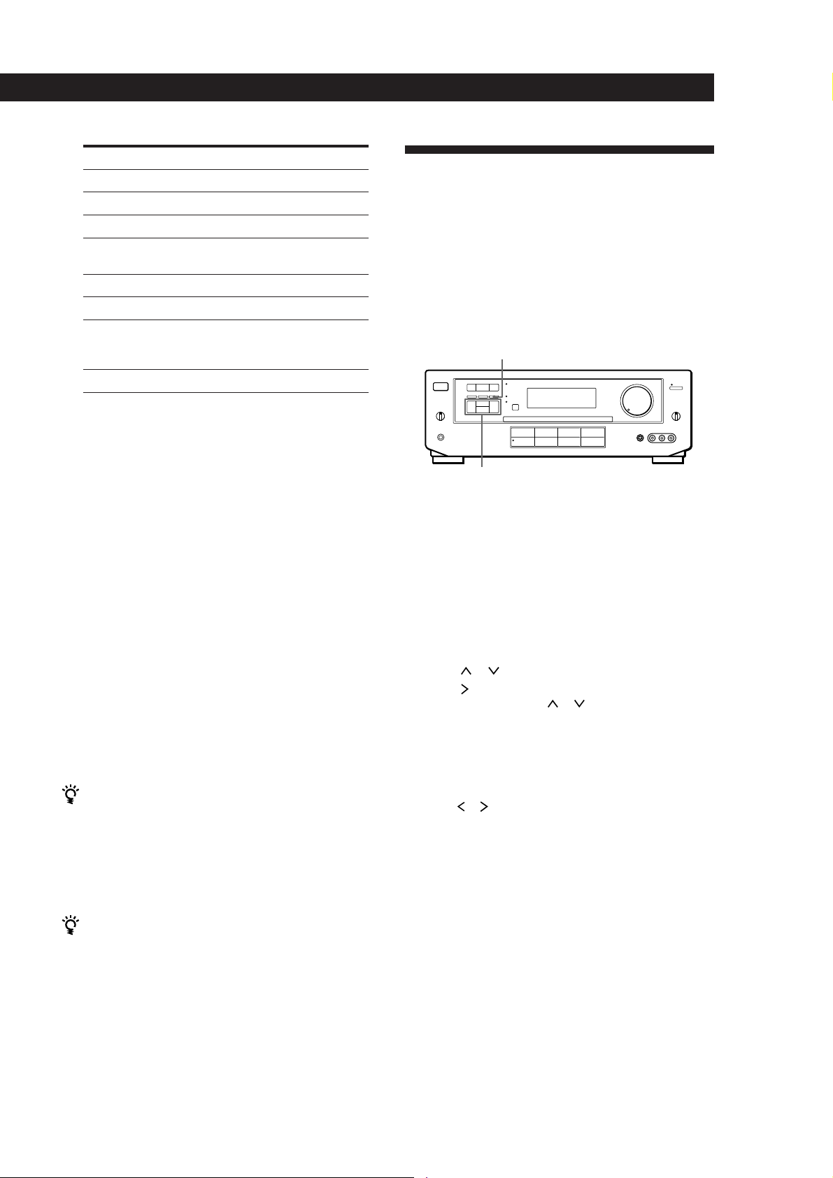
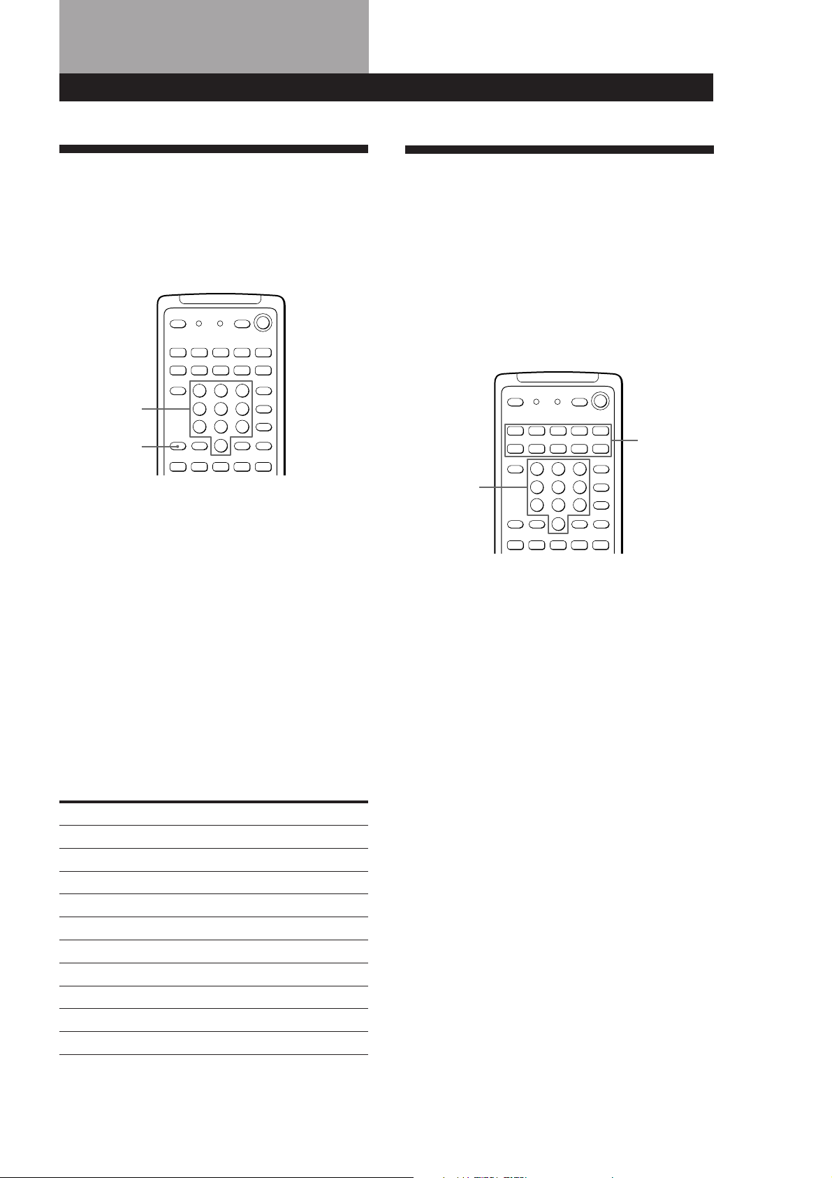
Indexing programme sources
This feature is useful when, for example, you have
more than one VCR: you can label one VCR as “VHS”
and label the other as “8MM”. Then, you can have the
amplifier display the index names so you can tell
which VCR you are using. This feature also comes in
handy if you connect a component to jacks designed
for another component (for example, connecting a
second CD player to the TUNER jacks).
DPC MODE
Digital
processing
control buttons
1 Press the function button you want to label.
2 Press DPC MODE repeatedly until the INDEX
indicator lights up.
2 Start playing.
Refer to “Remote Button Descriptions” on page 21
for details.
To turn off the components
Press SYSTEM OFF. This will also turn off the video and
audio components connected to the SWITCHED AC
OUTLETs on the back of this unit at the same time.
If you use a Sony TV
When you press TV to watch a TV programme, the TV
turns on and switches to the TV input. The TV also
turns on automatically and switches to the appropriate
video input when you press VIDEO 1 or VIDEO 2. If the
TV does not switch to the appropriate input
automatically, press TV/VIDEO on the remote.
Watching TV without the amplifier (for Sony TVs
only)
Press TV CONTROL ON to set the remote to operate TV
functions only (see “Remote Button Descriptions” on
page 21 for details). When you press this button, the TV
turns on and switches to the TV input. If the TV does
not automatically switch to the TV input, press TV/
VIDEO.
3 Create a name by using the digital processing
control buttons as follows:
Press
press
To insert a space, press or until a blank space
appears in the display (the space is between “}” and
“!”).
The name you created is stored automatically.
If you’ve made a mistake
Press or repeatedly until the character you want to
change flashes. Then select the right character.
or to select a character, and then
to move the cursor to the next position.
Note
Some Sony TVs cannot be controlled by this remote.
EN
9
Page 10
Amplifier Operations
Recording
This amplifier makes it easy to record to and from the
components connected to the amplifier. You don’t
have to connect playback and recording components
directly: once you select a programme source on the
amplifier, you can record and edit as you normally
would using the controls on each component.
Before you begin, make sure you’ve connected all
components properly.
2 Set the component to be ready for playing.
For example, insert the laser disc you want to
record from into the LD player.
3 Insert a blank video tape into the VCR (VIDEO 1
or VIDEO 2) for recording.
4 Start recording on the recording VCR and then
start playing the video tape or laser disc you want
to record.
You can replace audio while copying a video tape or
laser disc
At the point you want to start adding different sound,
press another function button (for example, CD) and
start playback. The sound from the selected component
will be recorded over the original audio.
c
Function buttons
c
ç
Playback component
(programme source)
ç: Audio signal flow
c: Video signal flow
ç
Recording component
(tape deck, MD deck,
VCR)
Recording on an audio tape or MiniDisc
You can record on a cassette tape or MiniDisc using the
amplifier. See the instruction manual of your cassette
deck or MD deck if you need help.
1 Press one of the function buttons to select the
component to be recorded.
2 Set the component to be ready for playing.
For example, insert a CD into the CD player.
3 Insert a blank tape into the recording deck and
adjust the recording level, if necessary.
4 Start recording on the recording deck and then
start playing the component.
To resume recording the sound of the original playback
source, press the function button for that component.
Using the Sleep Timer
You can set the amplifier to turn off automatically at a
time you specify.
SLEEP
Press SLEEP on the remote while the power is on.
Each time you press SLEEP, the time changes as shown
below.
n 2:00:00 n 1:30:00n 1:00:00 n 0:30:00 n OFF
10
EN
Recording on a video tape
You can record from a VCR, a TV, or an LD player
using the amplifier. You can also add audio from a
variety of audio sources when editing a video tape. See
your VCR or LD player’s instruction manual if you
need help.
1 Press one of the function buttons to select the
programme source to be recorded.
The display dims after you specify the time.
You can freely specify the time
Press SLEEP first, then specify the time you want using
the digital processing control ( or ) buttons. The
sleep time changes in 1 minute intervals. You can
specify up to 5 hours.
You can check the time remaining before the
amplifier turns off
Press SLEEP. The remaining time appears in the
display.
Page 11
Using Surround Sound
Using Pre-programmed Sound
Fields
You can take advantage of surround sound simply by
selecting one of the pre-programmed sound fields
according to the programme you want to play.
SOUND FIELD
ON/OFF
GENRE MODE
1 Press SOUND FIELD ON/OFF to turn on the
sound field.
One of the indicators lights up in the display.
2 Press GENRE to select the type of sound field you
desire.
3 Press MODE to select the mode you desire from
the respective genre.
Select the appropriate sound field according to
the chart shown at right.
To play without surround effects
Select “Acoustic” from MUSIC 2. The surround effects are
defeated but you can still adjust the tone parameter (see
page 12).
To turn off the sound fields
Press SOUND FIELD ON/OFF.
You can find Dolby Surround-encoded software by
looking at the packaging
However, some videos and laser discs may use Dolby
Surround sound even if it's not indicated on the
package.
Using Surround Sound
Sound Fields
GENRE MODE To
PRO LOGIC PRO LOGIC Decode programmes
processed with Dolby
Surround.
ENHANCED Provide additional
output to the rear
speakers after
decoding the Dolby
Surround programme
MOVIE SMALL THEATER Add the acoustic
reflections of a small
theater to decoded
Dolby Surround
signals.
LARGE THEATER Add the reflections of
a larger theater.
MONO THEATER Create a theater-like
environment from
movies with monaural
soundtracks.
MUSIC 1 SMALL HALL Reproduce the
acoustics of a small
rectangular concert
hall. Ideal for soft
acoustic sounds.
LARGE HALL Reproduce the
acoustics of a larger
hall.
MUSIC 2 KARAOKE Reduce the vocals of a
stereo music source.
ACOUSTIC Reproduce normal 2
channel stereo.
(No surround effects)
SPORTS ARENA Reproduce the feeling
of being in the front
row of a large concert
arena. Great for Rock
and Roll.
STADIUM Reproduce the feeling
of a large open-air
stadium. Great for
electric sounds.
GAME – Obtain maximum
audio impact from
video game software.
Note
Do not use both speakers (A+B) with SOUND FIELD set to
ON.
11
EN
Page 12
Using Surround Sound
Taking Advantage of the
Sound Fields
How can you customize the sound fields?
Each sound field is composed of sound parameters —
variables of sound that create sound image. You can
customize the sound fields by adjusting some of the
sound parameters to best suit your listening situation.
See the following chart for the adjustable sound
parameters.
Once you customize the sound fields, they are stored in
memory unless the amplifier is unplugged for about 1
week.
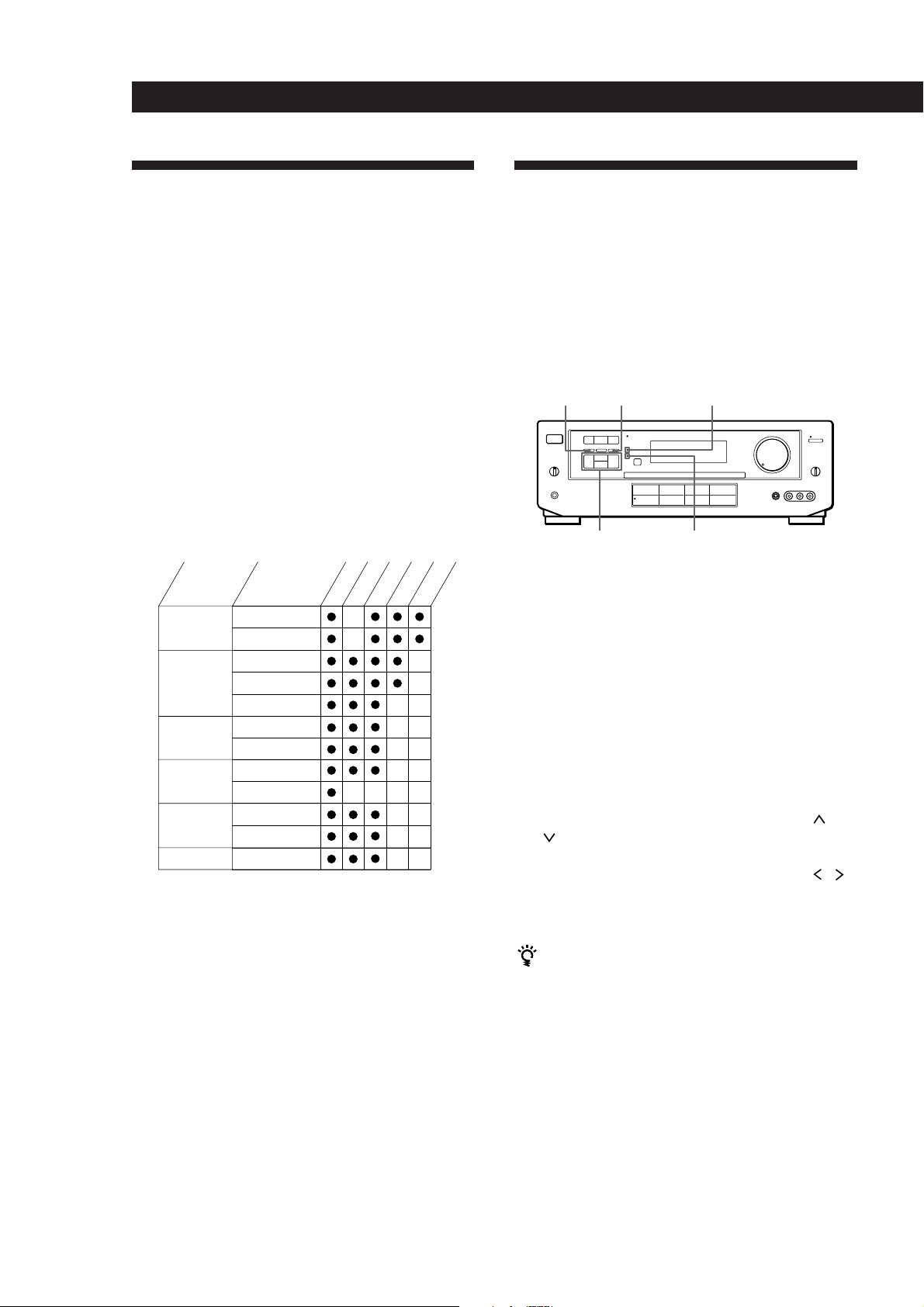
The adjustable parameters for each sound field are
shown on the charts below.
GENRE
PRO LOGIC
MOVIE
MUSIC 1
MUSIC 2
SPORTS
GAME
Note
The EFFECT parameter allows you to adjust the overall
presence of the sound field.
MODE
PRO LOGIC
ENHANCED
SMALL THEATER
LARGE THEATER
MONO MOVIE
SMALL HALL
LARGE HALL
KARAOKE
ACOUSTIC
ARENA
STADIUM
GAME
Before you get started
To take advantage of Dolby Pro Logic Surround sound,
go to “Getting the Most Out of Dolby Pro Logic
Surround Sound” on page 13. This section describes
how to adjust the levels of your speaker system and
customize the DOLBY SUR sound field.
TONE
EFFECT
REAR
DELAY
CENTER
Customizing Sound Fields
You can customize the sound fields by adjusting the
tone (bass or treble) and surround sound parameters
while listening to a programme source. The adjusted
parameters are stored in memory automatically and
you can use your custom sound fields just as you
would use the pre-programmed ones. Before you start,
select the sound field you want to customize and start
playing a programme.
SUR indicatorDPC MODETONE ON/OFF
Digital processing
control buttons
Adjusting the tone parameter
Adjust the tone (bass or treble) of the front, centre and
rear speakers for optimum sound. You can adjust the
tone of all sounds fields, including Dolby Surround.
1 Press TONE ON/OFF so that TONE ON appears
in the display.
2 Press DPC MODE repeatedly until the TONE
indicator lights up.
3 Use the digital processing control buttons ( /
) to select BASS or TREBLE.
4 Use the digital processing control buttons ( / )
to adjust the tone level.
The adjusted tone level is stored automatically.
You can turn off the tone adjustments without
erasing them
The tone adjustments and on/off setting are stored in
each sound field. Press TONE ON/OFF to turn the tone
parameter off or on.
TONE indicator
12
EN
Page 13
Using Surround Sound
Adjusting surround sound parameters
Change the surround parameters to fit your listening
situation. Refer to the chart on the previous page for
parameters you can adjust in each sound field.
To adjust the parameters of the DOLBY SUR sound
field, see “Getting the Most Out of Dolby Pro Logic
Surround Sound” on this page.
1 Press DPC MODE repeatedly until the SUR
indicator lights up.
2 Use the digital processing control buttons ( /
) to select the parameter you want.
3 Use the digital processing control buttons ( / )
to adjust the level of the parameter.
The adjusted parameters are stored automatically.
Note
If you make new adjustments to a sound field, the previous
settings are replaced by the new ones.
Resetting customized sound fields to the
factory settings
If the power is on, press POWER to turn off the
1
power.
2 Hold down SOUND FIELD ON/OFF and press
POWER.
“SURR CLEAR!” appears in the display and all
the sound fields are reset at once.
Note that you must have at least one additional pair of
speakers and/or one centre speaker to do the following
adjustments.
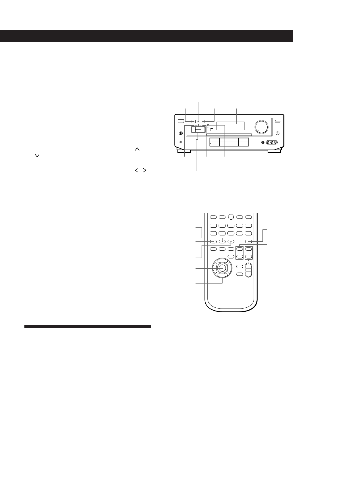
SOUND FIELD
ON/OFF
CENTER MODEMODEGENRE
TONE
ON/OFF
Digital processing
control buttons
Remote
GENRE
SOUND FIELD
ON/OFF
MODE
DPC MODE
DIGITAL
PROCESSING
CONTROL
MODE
SUR indicatorDPC
0)=+
9(p P r
TEST TONE
REAR
LEVEL (+/–)
CENTER
LEVEL (+/–)
Getting the Most Out of Dolby
Pro Logic Surround Sound
To obtain the best possible Dolby Pro Logic Surround
sound, first select the centre mode according to your
speaker system. Then, adjust the sound parameters of
the PRO LOGIC sound field.
Selecting the centre mode
The amplifier offers you four centre modes:
PHANTOM, 3 CHANNEL LOGIC, NORMAL, and
WIDE. Each mode is designed for a different speaker
configuration. Select the mode that best suits your
speaker system configuration.
1 Press SOUND FIELD ON/OFF to turn on the
sound fields.
2 Press GENRE to select the PRO LOGIC sound
field.
3 Press CENTER MODE repeatedly until the centre
mode you want appears in the display. Select the
centre mode by referring to the following chart.
(continued)
13
EN
Page 14
Using Surround Sound
If you have
Front and rear
speakers, no
centre speaker
Front and centre
speakers, no rear
speaker
Front and rear
speakers, and a
small centre
speaker
Front and rear
speakers, and a
centre speaker
equivalent to your
front speakers
Select
PHANTOM
3 CH LOGIC
(3 Channel
Logic)
NORMAL
WIDE
So that
The sound of the
centre channel is
output from the front
speakers.
The sound of the rear
channel is output
from the front
speakers.
The bass sound of the
centre channel is
output from the front
speakers (because a
small speaker cannot
produce enough
bass).
For “complete”
Dolby Pro Logic
Surround sound.
Adjusting the speaker volume
The test tone feature lets you set the volume of your
speakers to the same level. (If all of your speakers have
equal performance, you don’t have to adjust the
speaker volume.)
Adjusting the delay time
You can make the surround sound more effective by
delaying the output from the rear speakers (delay
time). You can adjust the delay time in 5 ms steps
within the range of 15 to 30 ms. For example, if you’ve
placed the rear speakers in a large room or apart from
your listening position, set the delay time shorter.
1 Start playing a programme source encoded with
Dolby surround sound.
2 Press DPC MODE until the SUR indicator lights
up.
3 Use the digital processing control buttons ( /
) to select the delay time.
The current delay time appears in the display.
4 Use the digital processing control buttons ( / )
to adjust the delay time.
Adjusting the tone
You can adjust the tone of the speakers.
Follow the procedure described in “Adjusting the tone
parameter” on page 12.
Using the controls on the remote lets you adjust the
volume level from your listening position.
1 Press TEST TONE on the remote.
You will hear the test tone from each speaker
sequentially.
2 Adjust the volume levels so that you hear the test
tone from each speaker at the same volume level
when you are in your listening position:
• To adjust the volume between the front right
and front left speakers, use the BALANCE
control on the front of the main unit.
• To adjust the level of centre speaker, press
CENTER LEVEL + or – on the remote.
• To adjust the level of rear speakers, press
REAR LEVEL + or – on the remote.
3 Press TEST TONE on the remote to turn off the
test tone.
You can adjust all speakers at one time
Adjust MASTER VOLUME.
14
EN
Page 15
Advanced Remote Operations
Operating One Component
While Using Another
(background operation)
You can temporality operate other components while
listening to or watching a programme.
Numeric
buttons
BACKGROUND
1 Hold down BACKGROUND.
2 Press both the corresponding numeric button of
the component you’re going to use (see the table
below) and one of the following buttons at the
same time; VISUAL POWER, TV/VIDEO, CH
PRESET +/–, ANT TV/VTR, D.SKIP, (, 9, p,
0/), =/+, P, r.
0)=+
Changing the Factory Setting
of a FUNCTION Button
If the factory settings of the FUNCTION buttons (page
9) don’t match your system components, you can
change them. For example, if you connect a Sony LD
player to the VIDEO 2 jacks, you can assign the VIDEO
2 button to set the remote to control the LD player.
Note that the settings of the TUNER and PHONO
buttons cannot be changed.
SYSTEM
CONTROL/
FUNCTION
Numeric
buttons
0)=+
1 Holding down the SYSTEM CONTROL/
FUNCTION button whose function you want to
change (VIDEO 2, for example).
Example:To start recording on a tape deck while
listening to a CD
While holding down BACKGROUND,
press 4 (or 5) and press r + ( at the
same time.
The numeric buttons are assigned to select the
functions as follows:
Numeric button Operates
1 CD player
2 DAT deck
3 MD deck
4 Tape deck A
5 Tape deck B
6 LD player
7 VCR (remote control mode VTR 1*)
8 VCR (remote control mode VTR 2*)
9 VCR (remote control mode VTR 3*)
0TV
* Sony VCRs are operated with a VTR 1, 2 or 3 setting.
These correspond to Beta, 8mm and VHS respectively.
2 Press the corresponding numeric button of the
component you want to assign to the SYSTEM
CONTROL/FUNCTION button (6 - LD player,
for example).
For the numeric buttons, see the table in
“Operating One Component While Using
Another.”
Now you can use the VIDEO 2 button to control
your Sony LD player.
To reset the setting to the factory setting
Repeat the above procedure.
15
EN
Page 16
Advanced Remote Operations
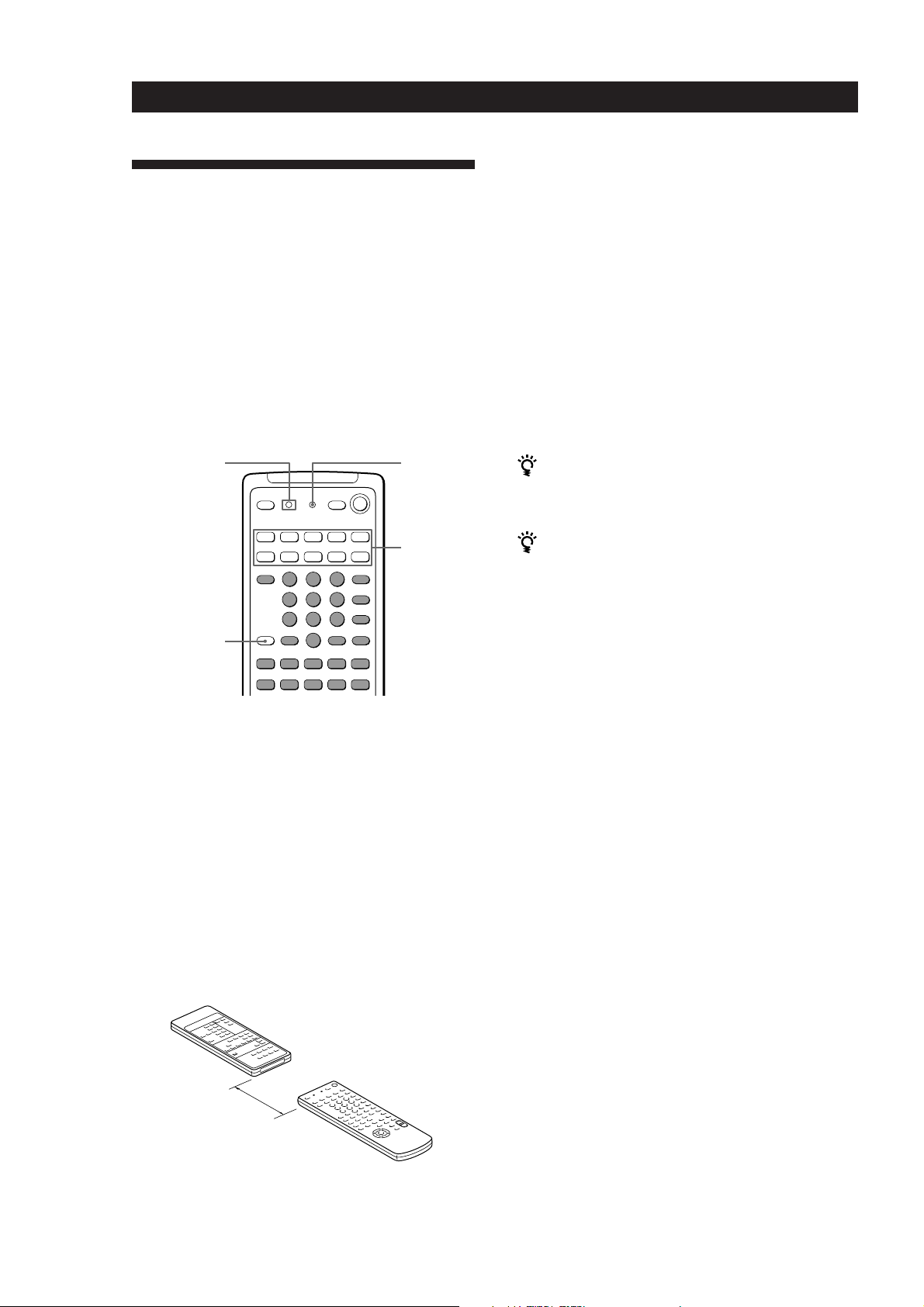
Programming the Remote
If the LEARN indicator flashes rapidly
You cannot use the button you’ve pressed.
The remote can control non-Sony components by
“learning” the control signals from their remotes. Once
this remote learns the other components signals, you
can use these components as part of your system.
Additionally, if you have any Sony components that
fail to operate with this remote, use this programming
function. This remote can “learn” signals only from
other infrared wireless remotes. Before you
programme signals, make sure that the two remotes:
• Face straight at each other (see Step 3 below)
• Are placed at a distance of about 5 cm
• Are not moved during programming
LEARN
indicator
BACKGROUND
0)=+
9(p P r
LEARN
SYSTEM
CONTROL/
FUNCTION
1 Press the SYSTEM CONTROL/FUNCTION
button of the component you want to programme.
For example, if you want to programme a CD
player’s remote, press CD.
2 Press LEARN to turn on the LEARN indicator.
3 Press the button on this unit’s remote that is to
“learn” the signal from the other remote.
The LEARN indicator flashes slowly.
Use only the shaded buttons shown above (see
“Remote Button Descriptions” on page 21 for the
buttons you can use to operate each component).
Other remote
4 On the other remote, select the function that the
amplifier’s remote is to “learn” and hold down its
button until the LEARN indicator lights steadily.
5 Repeat Steps 3 and 4 to programme other buttons.
Note that each button can only “learn” one signal
from another remote.
6 Press LEARN.
After the LEARN indicator turns off, you can
control the other component with the
programmed buttons.
When you programme the recording signal
While holding down the r button on the amplifier’s
remote and press the record button on the other remote.
If you cannot successfully programme signals, check
the following:
• If the LEARN indicator does not light up at all, the
batteries are weak. Replace both batteries.
• If the LEARN indicator does not flash or light up in
Step 3 or 4, there is interference. Clear the signal as
described in “Clearing the programmed signal”
below and programme again from the beginning.
• The two remotes are placed too far apart. Make sure
they are only 5 cm apart.
• If you don’t proceed to the following steps within
about 1 minute during Steps 2 and 3, the remote
automatically exits learning mode. Start again from
Step 2.
• If the memory in the remote has become full, (If you
programme signals of Sony components, you can
store about 60 signals.) you can programme a new
signal on a previously programmed button, but the
new signal will replace the previously programmed
one.
Notes
• You cannot turn on programmed components by pressing
a SYSTEM CONTROL/FUNCTION button. You have to
turn on the component's power switch.
• Do not programme remote signals of air conditioners or
other household appliances.
16
EN
About 5 cm
Amplifier’s remote
Clearing the programmed signal
To clear the programmed signals, do the following.
The button’s functions are reset to the factory-preset.
1 Press LEARN to turn on the LEARN indicator.
2 While holding down BACKGROUND, hold down
the button to be cleared until the LEARN
indicator turns off.
Page 17

Additional Information
Troubleshooting
If you experience any of the following difficulties while
using the amplifier, use this troubleshooting guide to
help you remedy the problem. Should any problem
persist, consult your nearest Sony dealer.
There’s no sound or only a very low-level sound is heard.
/ Check that the speakers and components are
connected securely.
/ Make sure you select the correct component
on the amplifier.
/ Make sure you set the SPEAKERS selector
correctly.
/ Press MUTING on the remote if MUTING is
shown in the display.
/ The protective device on the amplifier has
been activated because of a short circuit.
(“PROTECTOR” flashes.) Turn off the
amplifier, eliminate the short-circuit problem
and turn on the power again.
The left and right sounds are unbalanced or reversed.
/ Check that the speakers and components are
connected correctly and securely.
/ Adjust the BALANCE control.
Severe hum or noise is heard.
/ Check that the speakers and components are
connected securely.
/ Check that the connecting cords are away
from a transformer or motor, and at least 3
meters away from a TV set or fluorescent
light.
/ Place your TV away from the audio
components.
/ The plugs and jacks are dirty. Wipe them
with a cloth slightly moistened with alcohol.
Additional Information
No sound or only a very low-level sound is heard from
the rear speakers.
/ Turn on the sound field function.
/ Select the appropriate centre mode
(see page 13).
/ Adjust the speaker volume appropriately
(see page 14).
/ Make sure you turned on the sound field
function.
Surround effect cannot be obtained.
/ Turn on the sound field function.
/ Make sure that the SPEAKERS selector is set
to A+B when you use two sets of front
speakers.
No picture or an unclear picture is seen on the TV screen.
/ Select the appropriate function on the
amplifier.
/ Set your TV to the appropriate input mode
(press TV/VIDEO on the remote for Sony
TVs).
/ Place your TV away from the audio
components.
The remote does not function.
/ Point the remote at the remote sensor g on
the amplifier.
/ Remove the obstacles in the path of the
remote and the amplifier.
/ Replace both batteries in the remote with new
ones if they are weak.
/ Make sure you select the correct function on
the remote.
/ Pressing TV CONTROL ON sets the remote
to operate the TV only. In this case, press one
of the SYSTEM CONTROL/FUNCTION
buttons before operating the amplifier (etc.).
No sound is heard from the centre speaker.
/ Select a PRO LOGIC or MOVIE (except Mono
movie) sound field (see page 11).
/ Select the appropriate centre mode
(see page 13).
/ Adjust the speaker volume appropriately
(see page 14).
Recording cannot be made.
/ Check that the components are connected
correctly.
/ Select the source component with the
function buttons.
17
EN
Page 18
Additional Information
Specifications
Amplifier section
POWER OUTPUT
Stereo mode
Surround mode
Frequency
response
Inputs
Sensitivity
PHONO
(MM)
CD
TAPE/
MD,
TUNER,
VIDEO 1,
2, 3, TV/
LD
Outputs
(DIN 1 kHz, 4 ohms)
90 W + 90 W
(DIN 1 kHz, 4 ohms)
Front:
90 W/ch
Centre:
90 W
(only in the PRO
LOGIC mode)
Rear:
25 W
PHONO: RIAA
equalization curve
±0.5 dB
TUNER, CD, TAPE/MD,
VIDEO 1, 2, 3, TV/LD:
10 Hz - 50 kHz dB
Impedance
2.5 mV
kilohms
200 mV
150 mV
kilohms
TAPE/MD REC OUT,
VIDEO 1, 2 AUDIO
OUT: Voltage 150 mV,
Impedance 10 kilohms
MIX AUDIO OUT
Voltage: 2 V
Impedance: 1 kilohms
PHONES: Accepts low
and high impedance
headphones
50
50
+0
–1
S/N
(weighting
network,
input level)
75 dB**
(A, 2.5 mV)
82 dB**
(A, 150 mV)
** ‘78 IHF
Video section
Inputs
Outputs
VIDEO 1, 2, 3, TV/LD
VIDEO IN:
1 Vp-p 75 ohms
VIDEO 1, 3 S VIDEO:
Y: 1 Vp-p, unbalanced,
sync negative
C: 0.286 Vp-p,
load impedance
75 ohms
VIDEO 1, 2, MONITOR
VIDEO OUT:
1 Vp-p 75 ohms
VIDEO 1, MONITOR
S VIDEO:
Y: 1 Vp-p, unbalanced,
sync negative
C: 0.286 Vp-p,
load impedance
75 ohms
General
System
Power
requirements
Power
consumption
AC outlets
Dimensions
Mass (Approx.)
Supplied
accessories
Design and specifications are subject to
change without notice.
Preamplifier section: Low-
noise NF type equalizer
Power amplifier section:
Pure-complimentary SEPP
220-230 V AC, 50/60 Hz
230 W
1 switched, total 100 W
430 x 157 x 355 mm
1
/4 x 14 inches)
(17 x 6
10.5 kg (23 lb 3 oz)
Remote commander
(remote) (1)
Size AA (R6) batteries (2)
Glossary
Centre mode
Setting of speakers to enhance Dolby Pro
Logic Surround mode. To obtain the best
possible surround sound, select one of the
following four centre modes according to
your speaker system.
• NORMAL mode
Select NORMAL mode if you have front
and rear speakers and a small centre
speaker. Since a small speaker cannot
produce enough bass, the bass sound of
the centre channel is output from the front
speakers.
Front
speaker (L)
speaker (L)
Centre
speaker
Rear
• WIDE mode
Select WIDE mode if you have front and
rear speakers and a large centre speaker.
With the WIDE mode, you can take full
advantage of Dolby Surround sound.
Front
speaker (L)
Centre
speaker
Rear
speaker (L)
• PHANTOM mode
Select PHANTOM mode if you have front
and rear speakers but no centre speaker.
The sound of the centre channel is output
from the front speakers.
Front
speaker (L)
Front
speaker (R)
Rear
speaker (R)
Front
speaker (R)
Rear
speaker (R)
Front
speaker (R)
18
EN
Muting
BASS BOOST
TONE
– 20 dB
+10 dB at 70 Hz
±8 dB at 100 Hz and
10 kHz
Rear
speaker (L)
Rear
speaker (R)
Page 19
Additional Information
• 3 CH LOGIC mode
Select 3 CH LOGIC mode if you have front
and centre speakers but no rear speaker.
The sound of the rear channel is output
from the front speakers to let you
experience some of the surround sound
without using rear speakers.
Front
speaker (L)
Centre
speaker
Front
speaker (R)
Delay time
Time lag between the surround sound output
from front speakers and rear speakers. By
adjusting the delay time of the rear speakers,
you can obtain the feeling of presence. Make
the delay time longer when you have placed
the rear speakers in a small room or close to
your listening position, and make it shorter
when you have placed them in a large room
or apart from your listening position.
Dolby Pro Logic Surround
Decoding system of Dolby Surround sound
standardized in TV programmes and movies.
Compared with the former Dolby Surround
system, Dolby Pro Logic Surround improves
sound image by using four separate channels:
off-screen audio effects, on-screen dialog,
left-to-right panning, and music. These
channels manipulate the sound to be heard
and enhance the action as it happens on the
screen. To take advantage of Dolby Pro Logic,
you should have at least one pair of rear
speakers and/or one centre speaker. You also
need to select the appropriate centre mode to
enjoy a full effect.
Parameter
Variable of sound that composes sound
image, such as tone or delay time. You can
customize the pre-programmed sound fields
by adjusting parameters to suit your listening
situation.
Programmable remote
Remote control with “learning” capability.
You can control not only Sony components
but non-Sony components by programming
the control signals of these components.
Sound field
Sound pattern produced by a sounding
source or sources in a given environment due
to direct and reflected sounds and the
acoustics of the environment. The amplifier
offers 6 pre-programmed sound fields (PRO
LOGIC, MOVIE, MUSIC 1, MUSIC 2, SPORTS
and GAME) to let you enjoy surround sound
easily.
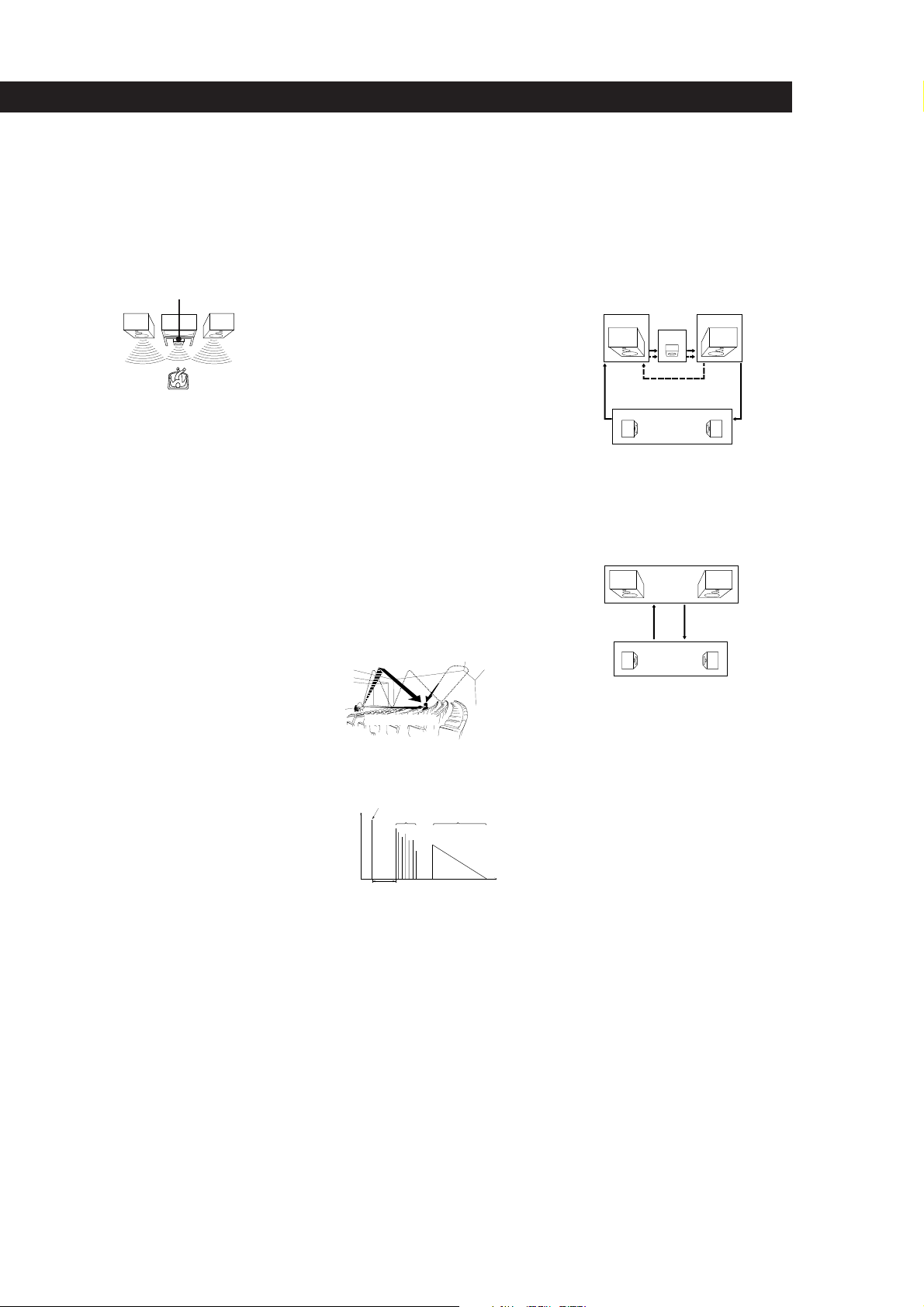
Surround sound
Sound that consists of three elements: direct
sound, early reflected sound (early
reflections) and reverberative sound
(reverberation). The acoustics where you hear
the sound affect the way these three sound
elements are heard. These sound elements are
combined in such a way that you can actually
feel the size and the type of a concert hall.
• Types of sound
Early reflections
Direct sound
Reverberation
• Transition of sound from rear speakers
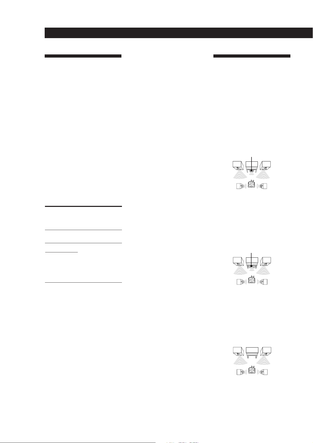
Test tone
Signal given out by the amplifier for
adjusting the speaker volume. The test tone
will come out as follows:
• In a system with a centre speaker
(NORMAL/WIDE/3 CH LOGIC modes)
The test tone is output from the front L
(left), centre, front R (right), and rear
speakers in succession.
Front (R)Front (L)
Centre
3 CH LOGIC
Rear (L, R)
NORMAL/WIDE
• In a system without a centre speaker
(PHANTOM mode)
The test tone is output from the front and
the rear speakers alternately.
Front (L, R)
PHANTOM
Rear (L, R)
Dolby Surround
Encoding and decoding system of Dolby
Surround sound for consumer use. Dolby
Surround decodes the extra channels on the
Dolby Surround-encoded sound tracks of
movie videos and TV programmes and
produces sound effects and echoes that make
the action seem to envelop you.
The amplifier offers Dolby Surround (PRO
LOGIC) as one of the pre-programmed sound
fields. If you have rear or centre speaker(s),
we recommend that you customize the Dolby
Surround sound field by selecting the
appropriate centre mode to take advantage of
Dolby Pro Logic Surround sound.
Effect level
Combination of the level of early reflections
and reverberation. You can adjust the effect
level in 6 levels. As you select higher levels,
the room becomes “live,” and as you select
lower levels, the room becomes “dead.”
Direct sound
Level
Early reflection time
Early
reflections Reverberation
Time
19
EN
Page 20

Rear Panel Descriptions
1 y ground terminal
2 MONITOR
3 TV/LD
4 VIDEO 2
5 VIDEO 1
6 MIX AUDIO OUT
54321
7 FRONT SPEAKERS (A/B)
8 SWITCHED AC OUTLET
9 mains lead
0 SURROUND SPEAKERS
(CENTER)
68
7
!¡!™!£!¢!∞
9
0
!¡ SURROUND SPEAKERS
(REAR)
!™ TAPE/MD
!£ CD
!¢ TUNER
!∞ PHONO
20
EN
Page 21

Remote Button Descriptions
For buttons not described on previous pages and buttons with names different from the buttons on the main unit.
Remote
Button
0-9
CH/PRESET
+/–
INDEX
D. SKIP
0/)
=/+
P
(
Operates
Tuner
CD player/MD
deck/LD player
TV/VCR
Tuner
TV/VCR
Tuner
CD player
CD player
Tape deck/MD
deck/VCR/LD
player
CD player/
MD deck/LD
player
CD player/
Tape deck/MD
deck/LD
player/VCR
CD player/
Tape deck/MD
deck/LD
player/VCR
Function
Selects preset numbers.
Selects track numbers.
0 selects track 10.
Selects channel numbers.
Scans and selects preset
stations.
Selects preset channels.
Selects station index
names for index select
tuning.
Skips discs (CD player
with multi-disc changer
only.)
Searches tracks (forward
or backward).
Fast forwards or rewinds.
Skips tracks.
Pauses play or record.
(Also starts recording
with components in
record standby.)
Starts play.
Remote
Button
RMS
DIRECTION
9/(
ENTER
TV/VIDEO
VISUAL
POWER
TV CONTROL
ON
-/- -
SUB CH +/–
POSITION
SWAP
P IN P
JUMP
ANT TV/VTR
Operates
Tape deck
TV/VCR
TV/VCR
TV/VCR/
LD player
TV
TV
TV
TV
TV
TV
TV
VCR
Function
Programmes tracks (tape deck
with the RMS* function only).
Changes channels when used
with 0-9.
Selects input signal: TV input
or video input.
Turns on or off the power.
Turns on the TV, switches the
input to “TV,” and sets the
remote to operate the TV.
Selects the channel entry
mode, either one or two digit
(in Europe only).
Selects preset channels for the
small picture.**
Changes the position of the
small picture.**
Swaps the small and the large
picture.**
Activates the picture-inpicture function.**
Jumps back and forth between
the previous and current
channels.
Selects output signal from the
antenna terminal: TV signal or
VCR programme.
p
9
r
r + (
RMS
DIRECTION
RMS CLEAR
CD player/
Tape deck/MD
deck/LD
player/VCR
Tape deck
Tape deck
Tape deck/
MD deck/
VCR
Tape deck
Tape deck
Stops play.
Starts play on the reverse
side.
Sets tape decks to the
record standby mode.
Starts recording when
pressed with ( (or 9
on tape deck).
Selects tape direction (for
tape decks with the RMS*
function.)
Clears RMS* programme
(for tape decks with the
RMS function.)
MASTER VOL
+/–
MUTING
SLOPE
BAND
* RMS: Random Music Sensor
** Only for Sony TVs with the picture-in-picture function
TV
TV
—
—
Normally, adjusts the master
volume of the amplifier.
If TV CONTROL ON was
pressed, it adjusts the volume
on the TV.
Normally, mutes the sound
from the amplifier.
If TV CONTROL ON was
pressed, the sound on the TV
itself is muted.
Not applicable.
Not applicable.
Note
Some Sony equipment cannot be controlled by this remote as
shown in the table above.
21
EN
Page 22

Index
A, B
Adjusting
delay time 14
parameter 12, 13
speaker volume 14
tone 12, 14
volume 8
Audio component hookups
5
Background operation 15
C
Centre mode 13, 18
NORMAL mode 14, 18
PHANTOM mode 14, 18
3 CH LOGIC mode 14, 19
WIDE mode 14, 18
Connecting. See Hookups
Customizing
remote 15, 16
sound field 12
D
Delay time 14, 19
Dolby Pro Logic
Surround 19
getting the most out of 13
Dolby Surround sound 11, 19
centre mode 13, 18
Dubbing. See Recording
E, F, G
Editing. See Recording
Effect level 12, 19
H
Hookups
audio components 5
mains lead 7
overview 4
speakers 5
TV/VCRs 6
I, J, K
Indexing
programme source 9
L, M
Labeling. See Indexing
N, O
NORMAL mode 14, 18
P, Q
Parameter 12, 13
PHANTOM mode 14, 18
Programme source
indexing 9
selecting 8
Programming the remote 16
clearing the signal 16
R
Random Music Sensor. See
RMS
Rear panel
5, 6, 7, 20
Recording
on an MD 10
on a tape 10
on a video tape 10
Remote 8, 10, 13, 15, 16, 21
changing the setting 15
controlling non-Sony
components 16
controlling Sony
components 8, 15
background operation 15
programming 16
RMS 21
S
Selecting a programme source
using the remote 8
Sleep timer 10
Sound field
adjustable parameters 12
customizing 12
pre-programmed 11
Speakers
connection 5
impedance 6
placement 5
selecting speaker system
6
Surround sound 11, 13, 19
T
Test tone 14, 19
3 CH LOGIC mode 14, 19
Troubleshooting 17
TV/VCR hookups 6
U, V
Unpacking 4
W, X, Y, Z
Watching video programmes
8
WIDE mode 14, 18
Names of controls
Buttons
ANT TV/VTR/D. SKIP 21
BACKGROUND 15
BASS BOOST 8
CD 8, 9
CENTER LEVEL 14
CENTER MODE 13
DIGITAL PROCESSING
CONTROLS 9, 12, 13
DPC MODE 9, 12, 13
GENRE 11, 13
LEARN 16
MASTER VOL 8, 14, 21
MODE 11, 13
MUTING 8
PHONO 8
REAR LEVEL 14
RMS CLEAR 21
9/( RMS DIRECTION 21
RMS/START/ENTER 21
SLEEP 10
SOUND FIELD
ON/OFF 11, 13
SYSTEM CONTROL/
FUNCTION 8, 15
SYSTEM OFF 8
TAPE/MD 8
TEST TONE 14, 19
TONE ON/OFF 12
TUNER 8, 9
TV/LD 8
TV CONTROL ON 8
TV/VIDEO 9, 21
VIDEO 1 8, 9
VIDEO 2 8, 9
VIDEO 3 8, 9
VISUAL POWER 21
/ / / 9, 12, 13, 14
0/) 21
=/+ 21
P 21
r 21
Numeric 15
Switch and selector
POWER 8
SPEAKERS 6
Controls
BALANCE 8
MASTER VOLUME 8, 14, 21
Jacks
PHONES 8
Indicators
DPC 9, 12, 13
LEARN 16
Other
g 4, 17
22
EN
Page 23

AVERTISSEMENT
Afin d’éviter tout risque
d’incendie ou
d’électrocution, éviter
d’exposer l’appareil à la
pluie ou à l’humidité.
Afin d’éviter tout risque d’incendie ou
d’électrocution, éviter
d’exposer l’appareil à la pluie ou à
l’humidité.
Afin d’écarter tout risque
d’électrocution, garder le coffret fermé.
Ne confier l’entretien de l’appareil qu’à
un personnel qualifié.
Précautions
Sécurité
• Si un solide ou un liquide tombait
dans le coffret, débranchez
l’amplificateur et faites-le vérifier par
un technicien qualifié avant de le
remettre en service.
Sources d’alimentation
• Avant de mettre en service
l’amplificateur, vérifiez que la tension
de fonctionnement correspond à celle
du courant secteur local. La tension
de fonctionnement est indiquée sur la
plaque signalétique à l’arrière de
l’amplificateur.
• L’amplificateur n’est pas déconnecté
de la source d’alimentation tant qu’il
est branché sur une prise murale,
même si vous le mettez hors tension.
• Si vous ne comptez pas utiliser
l’amplificateur pendant un certain
temps, débranchez-le de la prise
murale. Pour débrancher le cordon,
tirez sur la fiche et jamais sur le
cordon proprement dit.
• Si le cordon d’alimentation secteur
doit être remplacé, adressez-vous à
un technicien qualifié uniquement.
• L’interrupteur d’alimentation se
trouve en façade.
Fonctionnement
• Avant de raccorder d’autres
appareils, mettez l’amplificateur hors
tension et débranchez-le.
Nettoyage
• Nettoyez le coffret, le panneau et les
commandes avec un chiffon doux
légèrement imprégné d’une solution
détergente douce. N’utilisez pas de
tampon abrasif, poudre à récurer ou
solvant, comme de l’alcool ou de la
benzine.
En cas de question ou de problème
concernant l’amplificateur, consultez le
revendeur Sony le plus proche.
Installation
• Installez l’amplificateur dans un
endroit bien ventilé pour éviter tout
risque de surchauffe interne et
prolonger la durée de vie des
composants.
• N’installez pas l’amplificateur près
d’une source de chaleur, dans un
endroit en plein soleil, poussiéreux
ou exposé à des chocs mécaniques.
• Ne posez rien sur le coffret qui puisse
bloquer les orifices de ventilation et
provoquer un mauvais
fonctionnement.
F
2
Page 24
Au sujet de ce
manuel
Ce mode d’emploi décrit le
fonctionnement avec les commandes de
l’amplificateur. Vous pouvez également
utiliser les commandes de la
télécommande qui ont un nom
identique ou similaire à celles de
l’amplificateur.
• Le paragraphe “Nomenclature de la
télécommande” à la page 22 fournit
une description des commandes de la
télécommande.
• Les symbôles suivants sont utilisés
dans ce manuel:
Indique que vous pouvez utiliser
la télécommande pour effectuer
cette opération.
Donne des conseils
supplémentaires pour faciliter
l’utilisation.
Cet amplificateur utilise le système
surround Dolby Pro Logic.
Fabriqué sous licence de Dolby
Laboratories Licensing Corporation.
DOLBY, le symbole double-D a et
PRO LOGIC sont des marques de Dolby
Laboratories Licensing Corporation.
TABLE DES MATIÈRES
Préparatifs
Déballage 4
Description des raccordements 4
Raccordement de composants audio 5
Raccordement d’enceintes 5
Raccordement d’un téléviseur/magnétoscope 6
Raccordement au courant secteur 7
Avant la mise en service de l’amplificateur 7
Fonctionnement de l’amplificateur
Sélection d’un composant 8
Indexation d’une source de programme 9
Enregistrement 10
Programmation de l’arrêt automatique 11
Utilisation des champs sonores
Utilisation des champs sonores préréglés 12
Pour mieux profiter des champs sonores 13
Personnalisation des champs sonores 13
Pour mieux profiter du son surround Dolby Pro Logic 14
Fonctions élaborées pour le contrôle à distance
Utilisation simultanée de plusieurs composants
(Fonctionnement simultané) 16
Changement des réglages usine des touches de fonction 16
Programmation de la télécommande 17
F
Informations supplémentaires
Guide de dépannage 18
Spécifications 19
Glossaire 19
Nomenclature du panneau arrière 21
Nomenclature de la télécommande 22
Index 23
F
3
Page 25
Préparatifs
Déballage
Vérifiez si les accessoires suivants se trouvent dans
l’emballage.
• Télécommande (infrarouge) (1)
• Piles de format AA (R6) (2)
Mise en place des piles dans la
télécommande
Insérez deux piles de format AA (R6) en faisant
correspondre les bornes + et – avec le schéma dans le
logement. Pour utiliser la télécommande, dirigez-la
vers le détecteur infrarouge g sur l’amplificateur.
Description des raccordements
Vous pouvez raccorder à l’amplificateur les
composants audio/vidéo suivants. Selon les
composants que vous voulez raccorder à
l’amplificateur, reportez-vous aux pages indiquées
pour les démarches à suivre. Pour plus de détails sur
les différentes prises de l’amplificateur, reportez-vous
à “Nomenclature du panneau arrière” page 21.
Raccordement
d’un téléviseur/
Raccordement
d’enceintes
(5, 6)
Enceinte
avant
(gauche)
magnétoscope
(6, 7)
Téléviseur
Magnétoscope
Lecteur LD
Caisson
de grave
amplifié
Enceinte
avant
(droite)
Quand remplacer les piles
Dans des conditions d’utilisation normales, les piles
durent environ six mois. Quand vous ne pouvez plus
contrôler l’amplificateur avec la télécommande,
remplacez les piles par des neuves.
Remarques
• Ne laissez pas la télécommande dans un endroit
extrêmement chaud ou humide.
• N’insérez pas une pile neuve avec une vieille pile.
• N’exposez le détecteur infrarouge aux rayons directs du
soleil ou à un dispositif d’éclairage, pour ne pas
provoquer un mauvais fonctionnement.
• Si vous prévoyez de ne pas utiliser la télécommande
pendant longtemps, enlevez les piles pour éviter tout
dommage dû à une fuite d’électrolyte et à la corrosion.
Enceinte
arrière
(gauche)
Lecteur CD
Tuner
Platine à
cassette/MD
Tourne-disque
Raccordement de
composants audio (5)
Enceinte
centrale
Raccordement d’un
téléviseur/
magnétoscope (6,7)
Enceinte
arrière
(droite)
Camescope
Console de
jeux vidéo
Avant de commencer
• Mettez tous les composants hors tension avant
d’effectuer les connexions.
• Effectuez toutes les connexions avant de brancher le
cordon d’alimentation secteur.
• Enfoncez les fiches correctement pour éviter un
bourdonnement et du bruit.
• Lors du raccordement d’un câble audio/vidéo, faites
correspondre les broches codées par couleur aux
prises sur les composants: jaune (vidéo) à jaune,
blanc (audio, gauche) à blanc et rouge (audio, droit)
à rouge.
F
4
Page 26
Raccordement de composants
audio
Aperçu
Ce paragraphe explique comment raccorder des
composants audio à l’amplificateur. L’illustration cidessous indique l’emplacement des prises.
y
De quels cordons avez-vous besoin?
Vous avez besoin de cordons audio (non fournis) (1 pour le
lecteur CD et 1 pour le tuner (ou le tourne-disque si
nécessaire) et 2 pour la platine à cassette, ou la platine MD).
Blanc (gauche)
TAPE/MD
CDTUNERPHONO
Blanc (gauche)
Rouge (droit)Rouge (droit)
Préparatifs
• Si le tourne-disque est équipé d’un fil de terre
Raccordez le fil de terre à la borne y sur l’amplificateur
pour éviter tout un bourdonnement.
Que faire ensuite?
Passez au paragraphe suivant pour le raccordement des
enceintes.
Raccordement d’enceintes
Aperçu
Ce paragraphe explique comment raccorder des
enceintes à l’amplificateur. Vous devez raccorder des
enceintes avant (gauche et droite), cependant vous
pouvez choisir de raccorder ou non des enceintes
centrale, arrière et un caisson de grave amplifié.
Raccordez des enceintes centrale et arrière pour
accentuer l’effet surround. Raccordez un caisson de
grave amplifié pour accentuer la réponse dans les
basses fréquences.
L’illustration ci-dessous indique l’emplacement des
bornes sur l’amplificateur.
MIX AUDIO OUT FRONT SPEAKERS A
Raccordements
La flèche ç indique le sens du signal.
Lecteur CD
Amplificateur
IN
L
R
CD
Tuner
Amplificateur
IN
L
R
TUNER
Platine à cassette/MD
Amplificateur
INREC OUT
L
R
TAPE/MD
Tourne-disque
Amplificateur
IN
L
R
PHONO
Lecteur CD
OUTPUT
LINE
L
R
Tuner
OUTPUT
LINE
L
R
Cassette/MD
OUTPUT
INPUT
LINELINE
Tourne-disque
SURROUND
SPEAKERS REAR
SURROUND
SPEAKERS CENTER
Pour obtenir un effet surround optimum, positionnez
les enceintes comme illustré ci-dessous.
Enceinte arrière
60 - 90 cm
45°
Enceinte avant
De quels cordons avez-vous besoin?
• Vous avez besoin de cordons d’enceintes (non fournis) (1
pour chaque enceinte).
L
R
Dénudez environ 15 mm de gaine à chaque extrémité du
(+)
(–)
cordon. Veillez à faire correspondre les cordons d’enceintes
aux bornes des composants: + à + et – à –. Si les cordons sont
inversés, le son risque de présenter de la distorsion et de
manquer de graves.
• Cordon audio monophonique (non fourni) (pour un
caisson de grave amplifié)
Noir Noir
(voir page suivante)
(+)
(–)
F
5
Page 27
Préparatifs
Raccordements
Enceintes avant
Enceinte avant
(droite)
} ]
Pour raccorder les cordons d’enceintes
Amplificateur
FRONT SPEAKERS
IMPEDANCE USE 4-16 Ω
A
R
]}
Enceinte avant
(gauche)
A
L
≥
]}
Enceintes centrale et arrière
Enceinte arrière
(droite)
} ]} ]
Amplificateur
SURROUND SPEAKERS
REAR LR CENTER
LR
8-16Ω IMPEDANCE USE 4-16Ω Ω
Enceinte
centrale
} ]
} ]
Enceinte
arrière
(gauche)
Pour entraîner
Réglez le sélecteur
SPEAKERS sur:
Le système d’enceintes A (raccordé
aux bornes FRONT SPEAKERS A)
Le système d’enceintes B (raccordé
aux bornes FRONT SPEAKERS B)
Les deux systèmes d’enceintes A et B
(connexion parallèle)
* Ne pas utiliser A+B quand SOUND FIELD est sur ON.
A
B
A+B*
Que faire ensuite?
Si vous ne souhaitez pas raccorder d’autres composants,
allez au paragraphe “Raccordement au courant secteur”
page 7. Si vous voulez raccorder des composants vidéo pour
profiter du son surround en regardant la télévision ou une
cassette vidéo, allez au paragraphe suivant.
Raccordement d’un téléviseur/
magnétoscope
Aperçu
Ce paragraphe explique comment raccorder des
composants vidéo à l’amplificateur. L’illustration cidessous indique l’emplacement des prises.
Caisson de grave amplifié
Amplificateur
MIX
AUDIO
OUT
Caisson de grave amplifié
INPUT
Si vous avez des enceintes avant supplémentaires
Raccordez-les aux bornes FRONT SPEAKERS B.
Si le moniteur TV utilise des enceintes séparées
Vous pouvez raccorder une des enceintes aux bornes
SURROUND SPEAKER CENTER pour le son surround
Dolby Pro Logic (voir page 14).
Sélection du système d’enceintes
Si vous avez raccordé une seule paire d’enceintes
avant, réglez le sélecteur SPEAKERS du panneau avant
sur A. Si vous avez raccordé deux paires d’enceintes,
réglez le sélecteur en fonction du tableau suivant:
MONITOR
VIDEO 2TV/LD
VIDEO 1
De quels cordons avez-vous besoin?
• Vous avez besoin de cordons audio/vidéo (non fournis) (1
pour le téléviseur ou lecteur LD et 2 pour chaque
magnétoscope).
jaune
blanc (gauche)
rouge (droit) rouge (droit)
• Vous avez besoin également d’un cordon vidéo (non
fourni) (1 pour un moniteur TV).
jaune
jaune
blanc (gauche)
jaune
Si vous voulez voir des images vidéo de plus grande
qualité
Vous pouvez utiliser un cordon S-VIDEO (non fourni).
• Cordon S-VIDEO (non fourni)
F
6
Page 28

Raccordements
La flèche ç indique le sens du signal.
Moniteur TV
Si vous utilisez un moniteur TV, ne raccordez rien à la prise
TV/LD VIDEO IN.
Amplificateur
MONITOR
OUT
VIDEO
OUT
Magnétoscope (via les prises VIDEO 1)
Si vous avez deux magnétoscopes, raccordez le second aux
prises VIDEO 2.
Amplificateur
VIDEO 1
IN
OUT
VIDEO
VIDEO
IN
OUT
Moniteur TV
INPUT
VIDEO
Magnétoscope
OUTPUT
INPUT
VIDEO VIDEO
Préparatifs
Raccordement au courant
secteur
Branchement du cordon d’alimentation
secteur
Branchez le cordon d’alimentation secteur de
l’amplificateur et des composants audio/vidéo sur une
prise murale. Si vous avez raccordé des composants
audio à la SWITCHED AC OULET de l’amplificateur,
ils sont alimentés par l’amplificateur. Ainsi, tous les
composants se mettent sous/hors tension en même
temps que l’amplificateur.
SWITCHED AC OUTLET
AUDIO
AUDIO
IN
OUT
L
R
AUDIO AUDIO
TV ou lecteur LD (via les prises TV/LD)
Amplificateur
TV/LD
TV ou lecteur LD
VIDEO
IN
AUDIO
IN
L
R
OUTPUT
VIDEO
AUDIO
L
R
Camescope/Console de jeux vidéo
Utilisez les prises VIDEO 3 INPUT en façade.
Camescope ou
Amplificateur
VIDEO 3 INPUT
VIDEO L – AUDIO – R
console de jeux
OUTPUT
VIDEO
AUDIO
L
R
L
R
Précaution
Vérifiez que la consommation électrique des composants
raccordés à la prise secteur de l’amplificateur ne dépasse pas
à une prise murale
100 watts. Ne raccordez pas d’appareils électriques à
consommation élevée, comme un fer à repasser, un ventilateur
ou un téléviseur à cette prise.
Que faire ensuite?
/
Avant d’utiliser l’amplificateur, passez au paragraphe
suivant pour vérifier que toutes les commandes sont
correctement réglées.
Avant la mise en service de
l’amplificateur
Avant d’utiliser l’amplificateur, vérifiez que:
• Vous avez tourné la commande MASTER
VOLUME complètement à gauche (position 0).
• Vous avez sélectionné le système d’enceintes
adéquat. (Pour plus de détails, voir “Sélection du
système d’enceintes” page 6.)
• Vous avez réglé la commande BALANCE sur la
position centrale.
Que faire ensuite?
Passez au paragraphe suivant pour raccorder l’amplificateur
au courant secteur et ainsi terminer l’installation de votre
chaîne cinéma domestique.
Mettez l’amplificateur sous tension et vérifiez
l’indicateur suivant.
• Appuyez sur MUTING de la télécommande si
MUTING apparaît sur l’affichage.
F
7
Page 29

Fonctionnement de l’amplificateur
Sélection d’un composant
Pour écouter ou regarder un composant raccordé, vous
devez d’abord sélectionner la fonction sur
l’amplificateur ou avec la télécommande.
Avant tout, vérifiez que:
• Vous avez raccordé tous les composants
correctement comme indiqué aux pages 4 à 7.
• Vous avez tourné la commande MASTER VOLUME
complètement à gauche (position 0) pour éviter
d’endommager les enceintes.
POWER
PHONESSPEAKERS
Touches de fonction
1 Appuyez sur POWER pour mettre l’amplificateur
sous tension.
2 Appuyez sur une touche de fonction pour
sélectionner un composant:
Pour écouter ou regarder
Des disques analogiques
Des émissions de radio
Des disques compacts (CD)
Des cassettes audio ou des
minidisques (MD)
MASTER VOLUME
Appuyez sur
PHONO
TUNER
CD
TAPE/MD
Pour
Couper le son
Renforcer les graves
Régler la balance
Vous derez
Appuyer sur MUTING de la
télécommande.
Appuyez de nouveau pour
rétablir le son.
Appuyer sur BASS BOOST
pour allumer l’indicateur
BASS BOOST.
Tourner la commande
BALANCE vers la gauche ou
la droite.
Pour écouter avec un casque
Branchez le casque sur la prise PHONES et réglez le
sélecteur SPEAKERS sur OFF.
Pour regarder des programmes vidéo
Quand vous regardez la télévision ou un programme
vidéo, nous vous conseillons d’écouter le son par
l’amplificateur plutôt que par les haut-parleurs du
téléviseur. Ainsi, vous pourrez profiter du son
surround, comme le Dolby surround, et également
utiliser la télécommande de l’amplificateur pour
contrôler le son.
Eteignez d’abord les haut-parleurs du téléviseur pour
pouvoir écouter le son surround par l’amplificateur.
Pour regarder un programme TV, allumez le téléviseur et
l’amplificateur, puis appuyez sur la touche TV/LD de
l’amplificateur.
Pour regarder une cassette vidéo ou un disque laser,
effectuez les démarches suivantes:
1 Appuyez sur une touche de fonction pour
sélectionner le composant (par exemple, VIDEO
1).
Des cassettes vidéo
Des programmes télévisés
ou des disques laser
VIDEO 1, VIDEO 2 ou
VIDEO 3
TV/LD
2 Allumez le téléviseur et réglez l’entrée vidéo du
téléviseur en fonction du composant vidéo utilisé.
3 Allumez le composant (magnétoscope ou lecteur
LD) et démarrez la lecture.
3 Mettez le composant sous tension, par exemple le
lecteur CD, et démarrez la lecture.
4 Tournez la commande MASTER VOLUME pour
régler le volume.
Pour régler le volume des haut-parleurs du
téléviseur, utilisez la commande de volume du
téléviseur.
F
8
Utilisation de la télécommande
La télécommande vous permet de faire fonctionner
l’amplificateur et les composants Sony raccordés qui
peurent être contrôlés par la telécommande.
SYSTEM
OFF
SYSTEM
CONTROL/
TV CONTROL
ON
FUNCTION
Page 30

Fonctionnement de l’amplificateur
1 Appuyez sur une des touches SYSTEM
CONTROL/FUNCTION pour sélectionner le
composant à utiliser. L’amplificateur et le
composant sélectionné se mettent sous tension. Le
tableau suivant indique le réglage usine des
touches SYSTEM CONTROL/FUNCTION de la
télécommande.
Pour écouter ou regarder
Des disques analogiques
Des émissions de radio
Des disques compacts (CD)
Des cassettes
audionumériques (DAT) ou
des minidisques (MD)
Des cassettes audio
Des programmes TV
Des cassettes vidéo
Des disques lasers
* Les magnétoscopes Sony fonctionnent avec le réglage
VTR 1, 2 ou 3 qui correspondent respectivement à
Beta, 8 mm et VHS.
** VIDEO 3 et LD permettent à la télécommande
de faire fonctionner les composants vidéo Sony
correspondants mais ne permettent pas de changer la
fonction de l’amplificateur.
Par exemple, pour faire fonctionner un lecteur
LD Sony raccordé aux prises TV/LD (comme
indiqué page 7):
Appuyez sur TV pour sélectionner la
fonction, puis appuyez sur LD pour que la
télécommande puisse faire fonctionner le lecteur LD.
Si vous voulez changer le réglage usine d’une touche
Voir page 16.
Si le composant ne se met pas sous tension
Appuyez sur l’interrupteur d’alimentation sur le
composant.
Appuyez sur
PHONO
TUNER
CD
DAT/MD
TAPE
TV
VIDEO 1 (VTR 3*),
VIDEO 2 (VTR 1*) ou
VIDEO 3** (VTR 2*)
LD**
automatiquement sur l’entrée appropriée, appuyez sur
la touche TV/VIDEO de la télécommande.
Vous pouvez regarder la télévision sans utiliser
l’amplificateur (téléviseurs Sony uniquement)
Appuyez sur la touche TV CONTROL ON pour que la
télécommande contrôle le téléviseur uniquement (voir
“Nomenclature de la télécommande” page 22 pour plus
de détails). Quand vous appuyez sur cette touche, le
téléviseur se met sous tension et se règle sur l’entrée TV.
Si le téléviseur ne se règle pas automatiquement sur
l’entrée TV, appuyez sur TV/VIDEO.
Remarque
Certains téléviseurs Sony ne peuvent pas être pilotés par
cette télécommande.
Indexation des source de
programme
Cette fonction est intéressante quand vous avez, par
exemple, plusieurs magnétoscopes: vous pouvez ainsi
nommer un magnétoscope “VHS” et l’autre “8MM”. Le
nom d’index du magnétoscope que vous utilisez peut
alors être affiché. Cette fonction est également pratique
si vous raccordez un composant aux prises désignées
pour un autre composant (par exemple, quand vous
raccordez un second lecteur CD aux prises TUNER).
DPC MODE
Touches de
contrôle numérique
1 Appuyez sur la touche de fonction que vous
voulez définir par un index.
2 Démarrez la lecture.
Pour plus de détails, voir “Nomenclature de la
télécommande” page 22.
Pour mettre les composants hors tension
Appuyez sur SYSTEM OFF. Vous pouvez éteindre en même
temps tous les composants vidéo et audio raccordés à la
prise SWITCHED AC OUTLET à l’arrière de l’amplificateur.
Si vous utilisez un téléviseur Sony
Quand vous appuyez sur la touche TV pour regarder un
programme télévisé, le téléviseur s’allume et se règle
sur l’entrée TV. De même, le téléviseur se met
automatiquement sous tension et se règle sur l’entrée
vidéo appropriée quand vous appuyez sur la touche,
VIDEO 1 ou VIDEO 2. Si le téléviseur ne se règle pas
2 Appuyez plusieurs fois sur DPC MODE jusqu’à
ce que l’indicateur INDEX s’allume.
3 Créez un nom d’index avec les touches de
contrôle numérique, comme suit:
Appuyez sur ou pour sélectionner un
caractère, puis sur pour positionner le curseur
sur la position suivante. Pour insérer un espace,
appuyez sur ou jusqu’à ce qu’un espace
apparaisse sur l’affichage (l’espace se trouve entre
“}” et “!”).
L’index que vous avez créé est automatiquement
mémorisé.
En cas d’erreur
Appuyez plusieurs fois sur ou jusqu’à ce que le
caractère à modifier clignote, puis sélectionnez le
caractère correct.
F
9
Page 31

Fonctionnement de l’amplificateur
Enregistrement
Vous pouvez réaliser facilement des enregistrements
entre les différents composants raccordés à
l’amplificateur. Il n’est pas nécessaire de raccorder
directement les composants de lecture et
d’enregistrement, car une fois que vous avez
sélectionné la source de programme sur
l’amplificateur, vous pouvez procéder à
l’enregistrement ou au montage comme si vous
utilisiez les commandes de chaque composant.
Enregistrement sur une cassette vidéo
Vous pouvez enregistrer depuis un magnétoscope, un
téléviseur ou un lecteur LD en utilisant l’amplificateur.
Vous pouvez également ajouter le son de diverses
sources sonores pour le montage d’une cassette vidéo.
Pour plus de détails, consultez le mode d’emploi du
magnétoscope ou du lecteur LD.
1 Appuyez sur une des touches de fonction pour
sélectionner la source de programme à
enregistrer.
Avant de commencer, vérifiez que vous avez raccordé
correctement tous les composants.
c
Touches de fonction
c
ç
Appareil de lecture
(source de programme)
ç: Sens du signal audio
c: Sens du signal vidéo
ç
Appareil
d’enregistrement
(platine à cassette,
platine MD,
magnétoscope)
Enregistrement sur une cassette audio ou
un minidisque
Vous pouvez enregistrer sur une cassette audio, une
cassette audionumérique ou un minidisque en utilisant
l’amplificateur. Pour plus de détails, consultez le mode
d’emploi de la platine à cassette, ou de la platine DAT
ou MD.
2 Réglez le composant pour la lecture.
Par exemple, insérez un disque laser dans le cas
du lecteur LD.
3 Insérez une cassette vidéo vierge dans le
magnétoscope (VIDEO 1 ou VIDEO 2) pour
l’enregistrement.
4 Démarrez l’enregistrement sur le magnétoscope
enregistreur, puis commencez la lecture de la
cassette vidéo ou du disque laser à enregistrer.
Vous pouvez remplacer le son de la cassette vidéo
ou du disque laser enregistré
Au moment où vous vous voulez ajouter un autre son,
appuyez sur une autre touche de fonction (par exemple,
CD) et démarrez la lecture sur le composant. Le son du
composant sélectionné est enregistré à la place du son
original.
Pour enregistrer de nouveau le son original de
l’appareil de source, appuyez sur la touche de fonction
correspondante.
10
1 Appuyez sur une des touches de fonction pour
sélectionner l’appareil de source.
2 Réglez le composant pour la lecture.
Par exemple, insérez un CD dans le cas d’un
lecteur CD.
3 Insérez une cassette vierge dans l’enregistreur et
réglez le niveau d’enregistrement, si nécessaire.
4 Démarrez l’enregistrement sur l’enregistreur, puis
la lecture sur le composant.
F
Page 32

Programmation de l’arrêt
automatique
Vous pouvez régler l’amplificateur pour qu’il se mette
automatiquement hors tension.
SLEEP
Appuyez sur la touche SLEEP de la télécommande
pendant que l’amplificateur est en marche. Chaque fois
que vous appuyez sur SLEEP, le temps affiché change
comme indiqué ci-dessous:
Fonctionnement de l’amplificateur
n 2:00:00 n 1:30:00 n 1:00:00 n 0:30:00 n OFF
L’affichage s’assombrit une fois que vous avez désigné
le temps.
Vous pouvez désigner le temps de votre choix
Appuyez d’abord sur SLEEP, puis désignez le temps
souhaité avec les touches de contrôle numérique
( ou ). Le temps affiché change par intervalles d’une
minute. Vous pouvez choisir jusqu’à 5 heures de temps
de fonctionnement.
Vous pouvez vérifier le temps restant avant que
l’amplificateur ne se mette hors tension
Appuyez sur SLEEP. Le temps restant apparaît sur
l’affichage.
11
F
Page 33

Utilisation des champs sonores
Utilisation des champs sonores
préréglés
Vous pouvez profiter du son surround en sélectionnant
un des cinq champs sonores préréglés, en fonction du
programme écouté.
SOUND FIELD
ON/OFF
GENRE MODE
1 Appuyez sur SOUND FIELD ON/OFF pour
mettre le champ sonore en service.
Un des indicateurs s’allume sur l’affichage.
2 Appuyez sur GENRE pour sélectionner le type de
champ sonore souhaité.
3 Appuyez sur MODE pour choisir le mode
souhaité du genre sélectionné.
Sélectionnez le champ sonore qui convient en
vous référant au tableau de droite.
Pour écouter le son sans effets surround
Sélectionnez “Acoustic” à partir de MUSIC 2. Les effets
surround sont annulés, mais vous pouvez régler les timbres
(voir page 13).
Pour mettre les champs sonores hors service
Appuyez sur SOUND FIELD ON/OFF.
Vous pouvez reconnaître les programmes enregistrés
en Dolby Surround grâce à l’indication sur
l’emballage
Cependant, certains disques vidéo et laser peuvent
utiliser le son surround Dolby même si ce n’est pas
indiqué sur l’emballage.
Remarque
Ne pas utiliser les deux paires d’enceintes (A+B) quand
SOUND FIELD est sur ON.
Champs sonores
GENRE MODE Pour
PRO LOGIC PRO LOGIC Décoder des
programmes
enregistrés avec le
surround Dolby.
ENHANCED Fournir une sortie
complémentaire aux
enceintes arrière après
avoir décodé le
programme surround
Dolby.
MOVIE SMALL THEATER Ajouter les réflexions
acoustiques d’un petit
cinéma aux signaux
surround Dolby
décodés.
LARGE THEATER Ajouter les réflexions
typiques d’un grand
cinéma.
MONO THEATER Créer une ambiance
cinéma à partir de
films avec bande son
monophonique.
MUSIC 1 SMALL HALL Reproduire
l’acoustique d’une
petite salle de concert
rectangulaire. Idéal
pour des sons doux.
LARGE HALL Reproduire
l’acoustique d’une
grande salle.
MUSIC 2 KARAOKE Réduire les voix d’une
source musicale en
stéréo.
ACOUSTIC Reproduire le son
normal sur 2 canaux
(sans effets surround).
SPORTS ARENA Donner l’impression
d’être dans les
premiers rangs d’une
grande salle de
concert. Idéal pour le
rock and roll.
STADIUM Donner l’impression
d’être dans un grand
stade. Excellent pour
les sons électriques.
GAME – Obtenir un impact
sonore maximal des
jeux vidéo.
12
F
Page 34

Utilisation des champs sonores
Pour mieux profiter des
champs sonores
Comment personnaliser les champs
sonores?
Chaque champ sonore est composé de paramètres
variables qui créent l’image sonore. Vous pouvez
personnaliser les champs sonores en réglant certains de
ces paramètres. Reportez-vous au tableau suivant pour
connaître les paramètres réglables.
Une fois que vous avez personnalisé les champs
sonores, ils sont conservés en mémoire sauf si
l’amplificateur est débranché pendant environ 1
semaine.
Les paramètres réglables de chaque champ sonore sont
indiqués dans le tableau ci-dessous.
GENRE
PRO LOGIC
MOVIE
MUSIC 1
MUSIC 2
SPORTS
GAME
MODE
PRO LOGIC
ENHANCED
SMALL THEATER
LARGE THEATER
MONO MOVIE
SMALL HALL
LARGE HALL
KARAOKE
ACOUSTIC
ARENA
STADIUM
GAME
TONE
EFFECT
REAR
CENTER
DELAY
Personnalisation des champs
sonores
Vous pouvez personnaliser les champs sonores en
réglant les timbres (graves ou aigus) et les paramètres
surround pendant que vous écoutez une source de
programme. Les paramètres réglés sont
automatiquement mémorisés et vous pouvez les
utiliser de la même manière que les champs sonores
préréglés. Avant tout, sélectionnez le champ sonore
que vous voulez personnaliser et commencer la lecture
de la source de programme.
Indicateur SURDPC MODETONE ON/OFF
Indicateur TONETouches de contrôle
numérique
Réglage des timbres
Réglez les timbres (graves ou aigus) des enceintes
avant, centrale et arrière pour obtenir un son optimal.
Vous pouvez régler les timbres de tous les champs
sonores, y compris le Dolby surround.
1 Appuyez sur TONE ON/OFF pour que TONE
ON apparaisse sur l’affichage.
2 Appuyez plusieurs fois sur DPC MODE jusqu’à
ce que l’indicateur TONE s’allume.
3 Utilisez les touches de contrôle numérique
( / ) pour sélectionner BASS ou TREBLE.
Remarque
Le paramètre EFFECT permet de régler la présence générale
du champ sonore.
Préparatifs
Pour bénéficier pleinement du son surround Dolby Pro
Logic, voir “Pour mieux profiter du son surround
Dolby Pro Logic” à la page 14. Ce paragraphe explique
comment régler les niveaux des enceintes et
personnaliser le champ sonore DOLBY SUR.
4 Utilisez les touches de contrôle numérique
( / ) pour régler les timbres.
Le niveau réglé pour les timbres est
automatiquement mémorisé.
Vous pouvez annuler temporairement le réglage des
timbres sans l’effacer
Les réglages des timbres et de marche/arrêt sont
mémorisés pour chaque champ sonore. Appuyez sur la
touche TONE ON/OFF pour activer ou désactiver le
paramètre des timbres.
(voir page suivante)
13
F
Page 35

Utilisation des champs sonores
Réglage des paramètres surround
Changez les paramètres surround selon les conditions
d’écoute. Consultez le tableau de la page précédente
pour savoir quels paramètres vous pouvez régler pour
chaque champ sonore.
Pour régler les paramètres du champ sonore DOLBY
SUR, voir “Pour mieux profiter du son surround Dolby
Pro Logic” sur cette page.
1 Appuyez plusieurs fois sur DPC MODE jusqu’à
ce que l’indicateur SUR s’allume.
2 Utilisez les touches de contrôle numérique
( / ) pour sélectionner un paramètre.
3 Utilisez les touches de contrôle numérique
( / ) pour régler le niveau du paramètre.
Les paramètres réglés sont automatiquement
mémorisés.
Remarque
Si vous modifiez à nouveau un champ sonore, les réglages
précédents sont remplacés par les nouveaux.
Pour réinitialiser les champs sonores
personnalisés aux réglages usine
Pour pouvoir effectuer les réglages suivants, vous avez
besoin d’une seconde paire d’enceintes et/ou d’une
enceinte centrale.
SOUND FIELD
ON/OFF
CENTER MODEMODEGENRE
TONE
ON/OFF
Touches de contrôle
Télécommande
GENRE
SOUND FIELD
ON/OFF
MODE
DPC MODE
DPC
MODE
numérique
Indicateur SUR
0)=+
9(p P r
TEST TONE
REAR
LEVEL (+/–)
CENTER
LEVEL (+/–)
1 Si l’amplificateur est sous tension, appuyez sur
POWER pour le mettre hors tension.
2 Tenez SOUND FIELD ON/OFF enfoncée et
appuyez sur POWER.
“SURR CLEAR!” apparaît sur l’affichage et tous
les champs sonores sont réinitialisés.
Pour mieux profiter du son
surround Dolby Pro Logic
Afin d’obtenir le meilleur effet surround Dolby Pro
Logic possible, sélectionnez d’abord le mode de canal
central en fonction des enceintes utilisées. Ensuite,
réglez les paramètres du champ sonore PRO LOGIC.
DIGITAL
PROCESSING
CONTROL
Sélection du mode de canal central
Vous avez le choix entre quatre modes de canal central:
PHANTOM, 3 CHANNEL LOGIC, NORMAL et
WIDE. Chaque mode correspond à une configuration
d’enceintes différente. Sélectionnez le mode le mieux
adapté à la configuration de vos enceintes.
1 Appuyez sur SOUND FIELD ON/OFF pour
activer les champs sonores.
2 Appuyez sur GENRE pour sélectionner le champ
sonore PRO LOGIC.
3 Appuyez plusieurs fois sur CENTER MODE
jusqu’à ce que le mode de canal central souhaité
apparaisse sur l’affichage. Sélectionnez le mode
de canal central en fonction des indications du
tableau suivant.
14
F
Page 36

Utilisation des champs sonores
Si vous avez
Des enceintes
avant et arrière
mais pas
d’enceinte
centrale
Des enceintes
avant et centrale
mais pas
d’enceintes arrière
Des enceintes
avant et arrière et
une petite
enceinte centrale
Des enceintes
avant et arrière et
une enceinte
centrale
équivalente aux
enceintes avant
Sélectionnez
PHANTOM
3 CH LOGIC
(Logic 3 canaux)
NORMAL
WIDE
Pour que
Le son du canal
central soit fourni par
les enceintes avant.
Le son du canal
arrière soit fourni par
les enceintes avant.
Le son des graves du
canal central soit
fourni par les
enceintes avant (car
une petite enceinte ne
peut pas produire
assez de graves).
Le son surround
Dolby Pro Logic soit
“complet”.
Réglage du volume des enceintes
La tonalité d’essai permet de régler le volume de toutes
les enceintes sur le même niveau. (Si toutes les
enceintes ont la même puissance, il n’est pas nécessaire
de régler le volume.)
Utilisez la télécommande pour régler le volume depuis
votre position d’écoute.
Réglage du temps de retard
Vous pouvez renforcer l’efficacité du son surround en
retardant la sortie des enceintes arrière (temps de
retard). Vous pouvez régler le temps de retard par
intervalles de 5 ms dans une plage de 15 à 30 ms. Par
exemple, si les enceintes arrière se trouvent dans une
grande pièce ou loin de la position d’écoute, réglez un
temps de retard plus court.
1 Démarrez la lecture d’une source de programme
enregistrée en Dolby surround.
2 Appuyez sur DPC MODE jusqu’à ce que
l’indicateur SUR s’allume.
3 Utilisez les touches de contrôle numérique
( / ) pour sélectionner le temps de retard.
Le temps de retard actuel apparaît sur l’affichage.
4 Utilisez les touches de contrôle numérique
( / ) pour régler le temps de retard.
Réglage des timbres
Vous pouvez régler les timbres de chaque enceinte.
Suivez les étapes du paragraphe “Réglage des timbres”
à la page 13.
1 Appuyez sur la touche TEST TONE de la
télécommande.
La tonalité d’essai est fournie par chaque enceinte
l’une après l’autre.
2 Réglez les niveaux de volume de sorte que la
tonalité d’essai de chaque enceinte soit perçue au
même niveau depuis la position d’écoute:
• Pour régler le volume entre les enceintes avant
droite et avant gauche, utilisez la commande
BALANCE à l’avant de l’amplificateur.
• Pour régler le niveau de l’enceinte centrale,
appuyez sur la touche CENTER LEVEL + ou –
de la télécommande.
• Pour régler le niveau des enceintes arrière,
appuyez sur la touche REAR LEVEL + ou – de
la télécommande.
3 Appuyez sur la touche TEST TONE de la
télécommande pour arrêter la tonalité d’essai.
Vous pouvez régler le volume de toutes les
enceintes en même temps
Utilisez la commande MASTER VOLUME.
15
F
Page 37

Fonctions élaborées pour le contrôle à distance
Utilisation simultanée de
plusieurs composants
(Fonctionnement simultané)
Vous pouvez passer momentanément à un autre
composant pendant que vous écoutez ou regardez un
programme.
Touches
numériques
BACKGROUND
1 Tenez la touche BACKGROUND enfoncée.
2 Appuyez simultanément sur la touche numérique
correspondant au composant que vous utilisez
(voir le tableau ci-dessous) et sur l’une des
touches suivantes:
VISUAL POWER, TV/VIDEO, CH PRESET +/–,
ANT TV/VTR, D.SKIP, (, 9, p, 0/),
=/+, P, r.
Exemple:
Pour commencer un enregistrement sur
la platine à cassette pendant que vous
écoutez un CD
Tout en tenant la touche BACKGROUND
enfoncée, appuyez simultanément sur 4
(ou 5) et sur r + (.
0)=+
Changement des réglages
usine des touches de fonction
Si les réglages usine des touches de fonction (page 9)
ne correspondent pas aux composants que vous
utilisez, vous pouvez les changer. Par exemple, si vous
raccordez un lecteur LD Sony aux prises VIDEO 2,
vous pouvez désigner la touche VIDEO 2 pour le
contrôle du lecteur LD par la télécommande.
Toutefois, vous ne pouvez pas changer les réglages des
touches TUNER et PHONO.
SYSTEM
CONTROL/
Touches
numériques
0)=+
1 Tenez enfoncée la touche SYSTEM CONTROL/
FUNCTION dont vous voulez changer la fonction
(par exemple, VIDEO 2).
2 Appuyez sur la touche numérique correspondant
au composant que vous voulez assigner à la
touche SYSTEM CONTROL/FUNCTION (par
exemple, 6 - lecteur LD).
FUNCTION
16
Les touches numériques sélectionnent les fonctions
comme suit:
Touche numérique
1
2
3
4
5
6
7
8
9
0
* Les magnétoscopes Sony utilisent les modes de
télécommande VTR 1, 2 et 3 qui correspondent aux
F
systèmes Beta, 8 mm et VHS.
Pour sélectionner
Le lecteur CD
La platine DAT
La platine MD
La platine à cassette A
La platine à cassette B
Le lecteur LD
Le magnétoscope (mode de
télécommande VTR 1*)
Le magnétoscope (mode de
télécommande VTR 2*)
Le magnétoscope (mode de
télécommande VTR 3*)
Le téléviseur
Pour plus de détails sur les touches numériques,
voir le tableau “Utilisation simultanée de
plusieurs composants”.
A présent, vous pouvez utiliser la touche VIDEO
2 pour contrôler votre lecteur LD Sony.
Pour revenir aux réglages usine
Répéter les démarches ci-dessus.
Page 38

Fonctions élaborées pour le contrôle à distance
Programmation de la
télécommande
La télécommande peut piloter des appareils d’un autre
fabricant que Sony, si vous programmez les signaux de
contrôle de leurs télécommandes. Une fois que la
télécommande a appris les signaux des autres
appareils, vous pouvez les utiliser en tant que
composants de la chaîne. De même, si vous avez des
appareils Sony qui ne répondent pas aux signaux de la
télécommande de l’amplificateur, utilisez la fonction
de programmation. Cette télécommande peut
“apprendre” uniquement les signaux d’une
télécommande infrarouge. Avant la programmation,
vérifiez que les deux télécommandes:
• se trouvent face à face (voir l’étape 3 ci-dessous).
• se trouvent à une distance de 5 cm l’une de l’autre.
• ne sont pas déplacées pendant la programmation.
Indicateur
LEARN
LEARN
Si l’indicateur LEARN clignote rapidement
Vous ne pouvez pas utiliser la touche que vous avez enclenchée.
4 Sur l’autre télécommande, sélectionnez la fonction
que la télécommande de l’amplificateur doit
“apprendre” et tenez enfoncée la touche
correspondante jusqu’à ce que l’indicateur
LEARN reste allumé.
5 Répétez les étapes 3 et 4 pour programmer
d’autres touches. Chaque touche ne peut
“apprendre” qu’un seul signal d’une autre
télécommande.
6 Appuyez sur LEARN.
Une fois que l’indicateur LEARN est éteint, vous
pouvez piloter l’appareil avec les touches
programmées.
Pour programmer un signal d’enregistrement
Tout en tenant la touche r sur la télécommande de
l’amplificateur enfoncée, appuyez sur la touche
d’enregistrement de l’autre télécommande.
SYSTEM
CONTROL/
FUNCTION
BACKGROUND
0)=+
9(p P r
1 Appuyez sur la touche SYSTEM CONTROL/
FUNCTION de l’appareil à programmer.
Par exemple, si vous voulez programmer la
télécommande d’un lecteur CD, appuyez sur CD.
2 Appuyez sur LEARN de sorte que l’indicateur
LEARN s’allume.
3 Appuyez sur la touche de la télécommande de
l’amplificateur qui doit “apprendre” le signal de
l’autre télécommande. L’indicateur LEARN
clignote lentement. Utilisez seulement les touches
en gris indiquées ci-dessus (voir “Nomenclature
de la télécommande” à la page 22 pour savoir
quelles touches vous pouvez utiliser pour piloter
chaque composant).
Autre télécommande
Télécommande
de l’amplificateur
Environ 5 cm
Si vous ne parvenez pas à programmer des signaux,
vérifiez les points suivants:
• Si l’indicateur LEARN ne s’allume pas, les piles sont
faibles. Remplacez-les.
• Si l’indicateur LEARN ne clignote pas et ne s’allume
pas à l’étape 3 ou 4, il y a des interférences. Effacez le
signal comme indiqué dans le paragraphe
“Effacement d’un signal programmé” ci-dessous et
recommencez la programmation depuis le début.
• Les deux télécommandes sont trop loin l’une de
l’autre. Ne laissez pas plus de 5 cm entre les
télécommandes.
• Effectuez les étapes 2 et 3 en moins d’une minute
sinon la télécommande annule automatiquement le
mode d’apprentissage. Dans ce cas, recommencez à
partir de l’étape 2.
• Si la mémoire de la télécommande est pleine (vous
pouvez programmer jusqu’à 60 signaux d’appareils
Sony), vous pouvez programmer un nouveau signal
mais il remplacera un signal déjà programmé.
Remarques
• Vous ne pouvez pas mettre un appareil programmé sous
tension en appuyant sur la touche SYSTEM CONTROL/
FUNCTION. Vous devez utiliser l’interrupteur
d’alimentation de l’appareil.
• N’essayez pas de programmer les signaux d’un
climatiseur ou d’un autre appareil domestique.
Effacement d’un signal programmé
Pour effacer des signaux programmés, effectuez les
étapes suivantes. Les touches seront réinitialisées aux
réglages usine.
1 Appuyez sur LEARN de sorte que l’indicateur
LEARN s’allume.
2 Tout en tenant la touche BACKGROUND
enfoncée, appuyez sur la touche dont le
programme doit être effacé jusqu’à ce que
l’indicateur LEARN s’éteigne.
17
F
Page 39

Informations supplémentaires
Informations supplémentaires
Guide de dépannage
Si vous rencontrez des difficultés lors de l’utilisation de
l’amplificateur, consultez ce guide de dépannage pour
essayer de résoudre le problème. Toutefois, si le
problème persiste, consultez un revendeur Sony.
Pas de son ou son très faible en provenance des
enceintes arrière.
/ Activez le champ sonore.
/ Sélectionnez le mode de canal central
approprié (voir page 14).
/ Réglez le volume des enceintes correctement
(voir page 15).
/ Vérifiez que le champ sonore est activé.
Pas de son ou son extrêmement faible.
/ Vérifiez si les enceintes et les composants sont
correctement raccordés.
/ Vérifiez si vous avez sélectionné le bon
composant sur l’amplificateur.
/ Vérifiez si les touches SPEAKERS sont
correctement réglées.
/ Appuyez sur MUTING de la télécommande si
MUTING apparaît sur l’affichage.
/ Le dispositif de protection de l’amplificateur
s’est déclenché à cause d’un court-circuit.
(“PROTECTOR” clignote.) Mettez
l’amplificateur hors tension, éliminez la cause
du court-circuit, puis remettez l’amplificateur
sous tension.
Les sons des canaux gauche et droit sont déséquilibrés
ou inversés.
/ Vérifiez si les enceintes et les composants sont
correctement raccordés.
/ Réglez la commande BALANCE.
Bourdonnement ou parasites importants.
/ Vérifiez si les enceintes et les composants sont
correctement raccordés.
/ Assurez-vous que les cordons de
raccordement ne sont pas à proximité d’un
transformateur ou moteur et qu’ils se
trouvent à au moins 3 mètres d’un téléviseur
ou d’une lampe fluorescente.
/ Eloignez le téléviseur des composants audio.
/ Les fiches et les prises sont sales. Essuyez-les
avec un chiffon légèrement imprégné
d’alcool.
Impossible d’obtenir l’effet surround.
/ Activez le champ sonore.
/ Vérifiez que le sélecteur SPEAKERS est réglé
sur A+B quand vous utilisez deux paires
d’enceintes avant.
Pas d’image ou image de mauvaise qualité sur l’écran du
téléviseur.
/ Sélectionnez la fonction appropriée sur
l’amplificateur.
/ Réglez le téléviseur sur le mode d’entrée
approprié (appuyez sur la touche TV/VIDEO
de la télécommande dans le cas des
téléviseurs Sony).
/ Eloignez le téléviseur des composants audio.
La télécommande ne fonctionne pas.
/ Dirigez la télécommande vers le détecteur
infrarouge g de l’amplificateur.
/ Enlevez tout obstacle éventuel entre la
télécommande et l’amplificateur.
/ Si les piles de la télécommande sont faibles,
remplacez-les par des neuves.
/ Vérifiez que vous avez sélectionné la fonction
appropriée sur la télécommande.
/ Lorsque vous appuyez sur TV CONTROL
ON, la télécommande est réglée pour piloter
le téléviseur seulement. Dans ce cas, appuyez
sur une des touches SYSTEM CONTROL/
FUNCTION avant de faire fonctionner
l’amplificateur (etc.).
18
Aucun son ne sort de l’enceinte centrale.
/ Sélectionnez le champ sonore PRO LOGIC ou
MOVIE (sauf film monophonique)
(voir page 12).
/ Sélectionnez le mode de canal central
approprié (voir page 14).
/ Réglez le volume des enceintes correctement
(voir page 15).
Impossible d’enregistrer.
/ Vérifiez si les composants sont correctement
raccordés.
/ Sélectionnez l’appareil de source avec les
touches de fonction.
F
Page 40

Spécifications
Section amplificateur
Puissance de
sortie
Mode stéréo
Mode surround
Réponse en
fréquence
Entrées
Sensibilité
PHONO
(MM)
CD
TAPE/
MD,
TUNER,
VIDEO 1,
2, 3, TV/
LD
Sorties
Sourdine
BASS BOOST
(DIN 1 kHz, 4 ohms)
90 W + 90 W
(DIN 1 kHz, 4 ohms)
Avant: 90 W/cl
Centre: 90 W (seulement
en mode PRO LOGIC)
Arrière: 25 W
PHONO: RIAA
courbe d’égalisation
±0,5 dB
TUNER, CD, TAPE/MD,
VIDEO 1, 2, 3, TV/LD:
10 Hz - 50 kHz dB
Impédance
2,5 mV
kilohms
200 mV
150 mV
kilohms
TAPE/MD REC OUT,
VIDEO 1, 2 AUDIO
OUT: Tension 150 mV,
Impédance 10 kilohms
MIX AUDIO OUT
Tension: 2 V
Impédance: 1 kilohm
PHONES: Accepte des
casques de haute et
basse impédance
–20 dB
+10 dB à 70 Hz
50
50
+0
–1
S/B
(réseau
pondéré,
niveau
d’entrée)
75 dB**
(A, 2,5 mV)
82 dB**
(A, 150 mV)
** ‘78 IHF
Informations supplémentaires
Section vidéo
Entrées
Sorties
Généralités
Système
Alimentation
Consommation
électrique
Prise secteur
Dimensions
Poids (approx.)
Accessoires
fournis
La conception et les spécifications sont
modifiables sans préavis.
VIDEO 1, 2, 3, TV/LD
VIDEO IN:
1 Vc-c 75 ohms
VIDEO 1, 3 S VIDEO:
Y: 1 Vc-c, asymétrique,
sync. négative
C: 0,286 Vc-c,
impédance de charge
75 ohms
VIDEO 1, 2, MONITOR
VIDEO OUT:
1 Vc-c 75 ohms
VIDEO 1, MONITOR
S VIDEO:
Y: 1 Vc-c, asymétrique,
sync. négative
C: 0,286 Vc-c,
impédance de charge
75 ohms
Section préamplificateur:
Egaliseur type NF à
faible bruit
Section amplificateur de
puissance: Purement
complémentaire SEPP
Secteur 220-230 V,
50/60 Hz
230 W
1 commutée, total
100 W
430 x 157 x 355 mm
10,5 kg
Télécommande (1)
Piles de format AA (R6)
(2)
Glossaire
Mode de canal central
Ce réglage des enceintes accentue l’effet
surround Dolby Pro Logic. Pour obtenir le
meilleur effet surround possible, choisissez
un des quatres modes suivant selon la
disposition des enceintes.
• Mode NORMAL
Choisissez le mode NORMAL si vous
utilisez des enceintes avant et arrière avec
une petite enceinte centrale. Etant donné
qu’une petite enceinte ne peut pas
reproduire suffisamment de graves, le son
des graves du canal central est fourni par
les enceintes avant.
Enceinte
centrale
Enceinte
avant
(gauche)
Enceinte
arrière
(gauche)
• Mode WIDE
Choisissez le mode WIDE si vous utilisez
des enceintes avant et arrière avec une
grande enceinte centrale. Le mode WIDE
permet de profiter pleinement du son
surround Dolby.
Enceinte
centrale
Enceinte
avant
(gauche)
Enceinte
arrière
(gauche)
• Mode PHANTOM
Choisissez le mode PHANTOM si vous
avez des enceintes avant et arrière mais
pas d’enceinte centrale. Le son du canal
central est fourni par les enceintes avant.
Enceinte
avant
(gauche)
Enceinte
avant
(droite)
Enceinte
arrière
(droite)
Enceinte
avant
(droite)
Enceinte
arrière
(droite)
Enceinte
avant
(droite)
TONE
±8 dB à 100 Hz et 10 kHz
Enceinte
arrière
(gauche)
Enceinte
arrière
(droite)
19
F
Page 41

Informations supplémentaires
• Mode 3 CH LOGIC
Choisissez le mode 3 CH LOGIC si vous
avez des enceintes avant et centrale mais
pas d’enceintes arrière. Le son du canal
arrière est fourni par les enceintes avant, ce
qui permet de profiter un peu du son
surround même sans enceintes arrière.
Enceinte
centrale
Enceinte
avant
(gauche)
Enceinte
avant
(droite)
Temps de retard
C’est le temps qui s’écoule entre la sortie du
son surround des enceintes avant et des
enceintes arrière. En réglant le temps de
retard des enceintes arrière, vous pouvez
obtenir un effet de présence. Réglez un temps
de retard plus long si les enceintes arrière se
trouvent dans une petite pièce ou à proximité
de la position d’écoute et réglez un temps de
retard plus court si les enceintes arrière se
trouvent dans une grande pièce ou loin de la
position d’écoute.
Surround Dolby Pro Logic
C’est un système de décodage du son
surround Dolby utilisé pour les programmes
TV et les films. Comparé au système
surround Dolby précédent, le nouveau
système surround Dolby Pro Logic améliore
l’image sonore grâce à l’utilisation de quatre
canaux séparés: les effets sonores hors-écran
(off-screen), les dialogues sur écran (onscreen), le panorama gauche-droite et la
musique. Ces canaux manipulent le son afin
d’accentuer l’action en temps réel. Pour
pouvoir profiter pleinement de l’effet Dolby
Pro Logic, vous devez avoir au moins deux
enceintes arrière et/ou une enceinte centrale.
Vous devez également régler le mode de
canal central approprié.
Paramètre
C’est une composante du son, comme les
timbres ou le temps de retard, qui permet de
créer l’image sonore. Vous pouvez
personnaliser les champs sonores préréglés
en réglant les paramètres selon les conditions
d’écoute.
Télécommande programmable
C’est une télécommande qui peut
“apprendre” les signaux de commande d’un
autre appareil. Ceci permet de commander
non seulement des appareils Sony mais
également les appareils d’autres fabricants en
programmant les signaux de commande de
ces appareils.
Champ sonore
C’est le son produit par un ou des appareils
de source dans un environnement donné,
créé par les sons directs et réfléchis et
l’acoustique de la pièce. L’amplificateur
comprend 5 champs sonores préréglés (PRO
LOGIC, MOVIE, MUSIC 1, MUSIC 2, SPORTS
et GAME) pour pouvoir bénéficier facilement
du son surround.
Son surround
Le son surround comprend trois éléments: le
son direct, le son immédiatement réfléchi
(premières réflexions) et le son réverbéré
(réverbération). Ces trois éléments sont
affectés par l’acoustique de la pièce. La
combinaison de ces trois éléments permet de
recréer l’ambiance sonore d’une salle de
concert.
• Types de son
Premières réflexions
Son direct
Réverbération
Tonalité d’essai
Ce signal émis par l’amplificateur permet de
régler le volume des enceintes. La tonalité
d’essai fonctionne comme suit:
• Dans un système avec une enceinte
centrale (modes NORMAL/WIDE/3 CH
LOGIC)
La tonalité sort par l’enceinte avant
gauche, l’enceinte centrale, l’enceinte avant
droite, puis les enceintes arrière.
Enceinte
avant gauche
NORMAL/WIDE
Enceinte
centrale
3 CH LOGIC
Enceintes arrière
(gauche et
droite)
Enceinte
avant droite
• Dans un système sans enceinte centrale
(mode PHANTOM)
La tonalité d’essai sort par les enceintes
avant et arrière alternativement.
Enceintes avant (gauche et droite)
PHANTOM
Enceintes arrière
(gauche et
droite)
20
Surround Dolby
C’est un système de codage et de décodage
du son surround Dolby pour usage grand
public. Le système surround Dolby décode
les canaux supplémentaires des pistes
sonores codées en surround Dolby des films
vidéo et des programmes TV pour produire
des effets sonores et des échos qui donnent
l’impression de se trouver au coeur de
l’action.
L’amplificateur propose le surround Dolby
comme champ sonore préréglé. Si vous avez
des enceintes arrière ou centrale, nous vous
conseillons de personnaliser le champ sonore
surround Dolby en sélectionnant le mode de
canal central approprié pour pouvoir profiter
pleinement du son surround Dolby Pro
Logic.
• Evolution du son des enceintes arrière
Son direct
Niveau
Temps des premières
réflexions
Premières
réflexions
Réverbération
Temps
Niveau d’effet
C’est la combinaison du niveau des premières
réflexions et de la réverbération. Vous
pouvez régler ce niveau d’effet en 6 étapes.
Le fait de sélectionner un niveau plus élevé
rend la pièce plus “vivante”, tandis qu’un
niveau plus faible rend la pièce plus
“neutre”.
F
Page 42

Nomenclature du panneau arrière
76854321
9
0
!¡!™!£!¢!∞
1 y Borne de terre
2 MONITOR
3 TV/LD
4 VIDEO 2
5 VIDEO 1
6 MIX AUDIO OUT
7 FRONT SPEAKERS (A/B)
8 SWITCHED AC OUTLET
9 Cordon d’alimentation secteur
0 SURROUND SPEAKERS
(CENTER)
!¡ SURROUND SPEAKERS
(REAR)
!™ TAPE/MD
!£ CD
!¢ TUNER
!∞ PHONO
21
F
Page 43

Nomenclature de la télécommande
Commandes qui ne sont pas expliquées auparavant et dont les noms ne correspondent pas à ceux des commandes de
l’ampli-tuner.
22
Commande
0-9
CH/
PRESET
+/–
INDEX
D. SKIP
0/)
=/+
P
(
p
9
r
r + (
RMS
DIRECTION
Contrôle
Le tuner
Le lecteur CD/
platine MD/
lecteur LD
Le téléviseur/
magnétoscope
Le tuner
Le téléviseur/
magnétoscope
Le tuner
Le lecteur CD
Le lecteur CD
La platine à
cassette/platine
MD/
magnétoscope/
lecteur LD
Le lecteur CD/
platine MD/
lecteur LD
Le lecteur CD/
platine à
cassette/platine
MD/lecteur LD/
magnétoscope
Le lecteur CD/
platine à
cassette/platine
MD/lecteur LD/
magnétoscope
Le lecteur CD/
platine à
cassette/platine
MD/lecteur LD/
magnétoscope
La platine à
cassette
La platine à
cassette
La platine à
cassette/platine
MD/
magnétoscope
La platine à
cassette
Fonction
Sélection des numéros de
préréglage.
Sélection des numéros de
plage. 0 sert pour 10.
Sélection des numéros de
chaîne.
Balayage et sélection des
stations préréglées.
Sélection de chaînes
préréglées.
Sélection des noms d’index
de station pour l’accord
d’index.
Saut de disques (lecteur CD
avec changeur multi-disques
uniquement).
Recherche de plages (avant
ou arrière).
Recherche rapide avant ou
arrière.
Saut de plages.
Pause de lecture ou
d’enregistrement.
(Egalement pour démarrer
l’enregistrement sur les
composants en attente
d’enregistrement.)
Commencement de la
lecture.
Arrêt de la lecture.
Commencement de la lecture
sur la face arrière.
Réglage des platines à
cassette en mode d’attente
d’enregistrement.
Commencement de
l’enregistrement quand elle
est enclenchée
simultanément avec la
touche ( (ou 9 sur la
platine à cassette).
Sélection du sens de
défilement (platines à
cassette équipées de la
fonction RMS* uniquement).
F
Commande
RMS
CLEAR
RMS
DIRECTION
9/(
ENTER
TV/VIDEO
VISUAL
POWER
TV
CONTROL
ON
-/- -
SUB CH
+/–
POSITION
SWAP
P IN P
JUMP
ANT TV/
VTR
MASTER
VOL +/–
MUTING
SLOPE
BAND
*
RMS: Random Music Sensor (Détecteur aléatoire de musique)
** Uniquement pour les téléviseurs Sony équipés de la
fonction image dans l’image
Remarque
Certains appareils Sony ne peuvent pas être pilotés par cette
télécommande, tel qu’indiqué ci-dessus.
Contrôle
La platine à
cassette
La platine à
cassette
Le téléviseur/
magnétoscope
Le téléviseur/
magnétoscope
Le téléviseur/
magnétoscope/
lecteur LD
Le téléviseur
Le téléviseur
Le téléviseur
Le téléviseur
Le téléviseur
Le téléviseur
Le téléviseur
Le
magnétoscope
Le téléviseur
Le téléviseur
–
–
Fonction
Annulation du programme
RMS* (platines à cassette
équipées de la fonction RMS
uniquement).
Programmation de plages
(platines à cassette équipées de
la fonction RMS* uniquement).
Changement de chaînes avec
les touches 0-9.
Sélection du signal d’entrée:
entrée TV ou entrée vidéo.
Mise sous ou hors tension.
Mise sous tension du
téléviseur, réglage de l’entrée
sur “TV” et réglage de la
télécommande pour le contrôle
du téléviseur.
Sélection du mode d’entrée du
numéro de chaîne, soit un ou
deux chiffres. (en Europe
uniquement)
Sélection des chaînes préréglées
pour l’image incrustée.**
Changement de position de
l’image incrustée.**
Inversion de la petite et de la
grande image.**
Activation de la fonction
image dans l’image.**
Alternance entre la chaîne
actuelle et la chaîne précédente.
Sélection du signal de sortie de
la borne d’antenne: signal du
téléviseur ou du magnétoscope.
Normalement, réglage du
volume général de
l’amplificateur.
Si TV CONTROL ON a été
enclenchée, réglage du volume
du téléviseur.
Normalement, coupure du son
de l’amplificateur.
Si TV CONTROL ON a été
enclenchée, coupure du son du
téléviseur.
Non utilisable
Non utilisable
Page 44

Index
A, B, C
Champs sonores
Champs sonores préréglés
12
Paramètres réglables 13
Personnalisation 13
Connexions Voir
Raccordements
Copie Voir enregistrement
D
Déballage 4
Détecteur aléatoire de
musique. Voir RMS
E, F
Enceintes
Impédance 6
Positionnement 5
Raccordement 5
Sélection du système
d’enceinte 6
Enregistrement
sur un MD 10
sur une cassette 10
sur une cassette vidéo 10
G, H
Guide de dépannage 18
I, J, K, L
Indexation
des sources de programme
9
M
Mode de canal central 14, 19, 20
Mode NORMAL 14, 19
Mode PHANTOM 14, 20
Mode 3 CH LOGIC 14, 19
Mode WIDE 14, 19
Montage Voir Enregistrement
N, O
Niveau d’effet 13, 20
P, Q
Panneau arrière 5, 6, 7, 21
Paramètre 13, 14
Personnalisation
Télécommande 16, 17
Champs sonores 13
Pour regarder des programmes
vidéo 8
Programmation de la
télécommande 17
Effacement du signal 17
R
Raccordement d’un téléviseur/
magnétoscope 6
Raccordement de composants
audio 5
Raccordements
Description 4
Composants audio 5,
Cordon d’alimentation
Secteur 7
Enceintes 5
Téléviseur/magnétoscope
6
Réglage
des paramètres surround
13, 14
des timbres 13
du temps de retard 15
du volume 8
du volume des enceintes
15
RMS 21
S
Sélection d’une source de
programme avec la
télécommande 8
Son surround 12, 14, 20
Son surround Dolby 20
Mode de canal central 14,
20
Son surround Dolby Pro
Logic 20
Pour mieux profiter du son
surround Dolby Pro Logic
14
Source de programme
Indexation 9
Sélection 8
T
Temps de retard 15, 20
Tonalité d’essai 15, 20
Télécommande 8, 11, 14, 16,
17, 22
Changement des réglages
16
Contrôle d’un appareil
d’une autre marque 17
Contrôle d’un appareil
Sony 8, 16
Utilisation simultanée de
plusieurs composants 16
Programmation 17
U, V, W, X, Y, Z
Utilisation simultanée de
plusieurs composants 16
Nomenclature
Touches
ANT TV/VTR/D. SKIP 22
BACKGROUND 16
BASS BOOST 8
CD 8, 9
CENTER LEVEL 15
CENTER MODE 14
DIGITAL PROCESSING
CONTROLS 9, 13, 14
DPC MODE 9, 13, 14
GENRE 12, 14
LEARN 17
MASTER VOLUME 8, 15, 22
MODE 12, 14
MUTING 8
PHONO 8
REAR LEVEL 15
RMS CLEAR 22
9/( RMS DIRECTION 22
RMS/START/ENTER 22
SLEEP 11
SOUND FIELD ON/OFF 12,
14
SYSTEM CONTROL/
FUNCTION 9, 16
SYSTEM OFF 8
TAPE/MD 8
TEST TONE 15, 20
TONE ON/OFF 13
TUNER 8, 9
TV/LD 8
TV CONTROL ON 9
TV/VIDEO 9, 22
VIDEO 1 8, 9
VIDEO 2 8, 9
VIDEO 3 8, 9
VISUAL POWER 22
/ / / 9, 13, 14, 15
0/) 22
=/+ 22
P 22
r 22
Numériques 16
Interrupteurs et sélecteurs
POWER 8
SPEAKERS 6
Commandes
BALANCE 8
MASTER VOLUME 8, 15, 22
Prises
PHONES 8
Indicateurs
DPC 9, 13, 14
LEARN 17
Autres
g 4, 18
23
F
Page 45

Preparativos
ADVERTENCIA
Para evitar incendios y el
riesgo de electrocución, no
exponga la unidad a la
lluvia ni a la humedad.
Para evitar descargas eléctricas, no abra
la unidad. En caso de avería, solicite los
servicios de personal cualificado.
No instale el aparato en un espacio
cerrado, como una estantería para libros
o un armario empotrado.
Precauciones
Seguridad
• Si dentro del amplificador cae algún
objeto sólido o líquido, desenchúfelo
y haga que sea revisado por personal
cualificado.
Fuentes de alimentación
• Antes de utilizar el amplificador,
compruebe si su tensión de
alimentación es idéntica a la de la red
local. La tensión de alimentación está
indicada en la placa de características
de la parte posterior del amplificador.
• El amplificador no se desconectará de
la fuente de alimentación de CA (red)
mientras permanezca enchufado a
una toma de la misma, incluso
aunque ponga en OFF su interruptor
de alimentación.
• Cuando no vaya a utilizar el
amplificador durante mucho tiempo,
desenchúfelo de la red. Para
desconectar el cable de alimentación,
tire del enchufe. No tire nunca del
propio cable.
• El cable de alimentación de CA
solamente deberá ser cambiado en un
taller de reparaciones cualificado.
• El interruptor de alimentación
principal se encuentra en la parte
frontal exterior.
Limpieza
• Limpie la caja, los paneles, y los
controles con un paño suave
ligeramente humedecido en una
solución poco concentrada de
detergente. No utilice ningún tipo de
estropajos, polvos abrasivos, ni
disolventes como alcohol o bencina.
Si tiene cualquier pregunta o
problema en relación con su
amplificador, consulte a su
proveedor Sony más cercano.
Ubicación
• Coloque el amplificador en un lugar
adecuadamente ventilado para evitar
el recalentamiento interior y
prolongar su duración útil.
• No coloque el amplificador cerca de
fuentes térmicas, ni sometido a la luz
solar directa, polvo excesivo, ni a los
golpes.
• No coloque nada sobre el
amplificador, ya que podría bloquear
los orificios de ventilación y provocar
su mal funcionamiento.
Operación
• Antes de conectar otros componentes,
cerciórese de poner en OFF el
interruptor de alimentación de este
amplificador y de desconectarlo de la
toma de la red.
E
2
Page 46

Preparativos
Descripción de este
manual
En este manual de instrucciones se
describen los controles del amplificador.
Usted también podrá utilizar los
controles del telemando si poseen
nombres iguales o similares a los del
amplificador.
• En la sección “Descripción de las
teclas del telemando” de la página 23
se ofrece un resumen de las teclas de
dicho telemando.
• En este manual se utilizan los iconos
siguientes:
Indica que usted podrá utilizar el
telemando para realizar la tarea.
Indica consejos y sugerencias
para facilitar las tareas.
Este amplificador posee el sistema
Dolby Surround.
Fabricado bajo licencia de Dolby
Laboratories Licensing Corporation.
DOLBY, el símbolo de la doble D a y
PRO LOGIC son marcas de Dolby
Laboratories Licensing Corporation.
ÍNDICE
Preparativos
Desembalaje 4
Descripción general de las conexiones 4
Conexión de componentes de audio 5
Conexión de sistemas de altavoces 5
Conexión de un televisor/videograbadora 6
Conexión de CA 7
Antes de utilizar su amplificador 8
Operaciones del amplificador
Selección de un componente 9
Indización de nombres de fuentes de programas 11
Grabación 11
Utilización del temporizador cronodesconectador 12
Utilización de campos acústicos
Utilización de campos acústicos programados 13
Para aprovechar las ventajas de los campos acústicos 14
Personalización de los campos acústicos 14
Disfrute al máximo de sonido Dolby Pro Logic Surround 15
E
Operaciones remotas avanzadas
Control de un componente durante la utilización de otro
(Operación de fondo) 17
Cambio del ajuste de fábrica de una tecla de función 17
Programación del telemando 18
Información adicional
Solución de problemas 19
Especificaciones 20
Glosario 20
Descripción del panel posterior 22
Descripción de las teclas del telemando 23
Índice alfabético 24
E
3
Page 47

Preparativos
Preparativos
Desembalaje
Compruebe si ha recibido los accesorios siguientes con
el amplificador:
• Telemando (1)
• Pilas de tamaño AA (R6) (2)
Colocación de las pilas en el telemando
Inserte dos pilas de tamaño AA (R6) de acuerdo con +
y – del compartimiento de las mismas. Cuando utilice
el telemando, apunte con él hacia el sensor de control
remoto g del amplificador.
Descripción general de las
conexiones
El amplificador le permitirá conectar y controlar los
componentes de audio/vídeo siguientes. Para conectar
al amplificador los componentes deseados, siga los
procedimientos de las páginas especificadas. Para
aprender la ubicación y el nombre de cada toma,
consulte “Descripción del panel posterior” de la página
22.
Conexión de un
televisor/
Conexión de
un sistema de
altavoces (5, 6)
Altavoz
delantero
(izquierdo)
videograbadora
(6, 7)
Televisor
Videograbadora
Reproductor de
discos láser
Altavoz
de graves
activo
Altavoz
delantero
(derecho)
Cuándo reemplazar las pilas
En utilización normal, las pilas durarán unos 6 meses.
Cuando el telemando no pueda controlar el
amplificador, reemplace ambas pilas por otras nuevas.
Notas
• No deje el telemando en un lugar extremadamente cálido
ni húmedo.
• No utilice una pila nueva con otra vieja.
• No exponga el sensor de control remoto a la luz solar
directa ni a la de aparatos de iluminación. Si lo hiciese,
podría causar un mal funcionamiento.
• Cuando no vaya a utilizar el telemando durante mucho
tiempo, extráigale las pilas a fin de evitar el daño que
podría causar el electrólito de las mismas.
Altavoz
trasero
(izquierdo)
de audio (5)
Reproductor de
discos compactos
Sintonizador
Deck de cassettes/
deck de minidiscos
Giradiscos
Altavoz
central
Videocámara
Conexión de un
videograbadora (6, 7)Conexión de componentes
Altavoz
trasero
(derecho)
Videojuego
televisor/
Antes de comenzar
• Antes de realizar cualquier conexión, desconecte la
alimentación de todos los componentes.
• No conecte el cable de alimentación de CA antes de
haber realizado todas las conexiones.
• Cerciórese de realizar conexiones firmes para evitar
zumbidos y ruidos.
• Cuando conecte un cable de audio/vídeo, cerciórese
de hacer coincidir las clavijas codificadas en color
con las tomas apropiadas de los componentes.
Amarilla (vídeo) a amarilla, blanca (canal izquierdo
de audio) a blanca, y roja (canal derecho de audio) a
roja.
E
4
Page 48

Conexión de componentes de
audio
Descripción general
En esta sección se describe cómo conectar sus
componentes de audio al amplificador.
Con respecto a la ubicación específica de los
terminales, consulte la ilustración siguiente.
Preparativos
Giradiscos
Amplificador Giradiscos
IN
L
R
PHONO
• Si su giradiscos posee conductor de puesta a tierra
Para evitar zumbidos, conecte el conductor de puesta a
tierra al terminal de tierra y del amplificador.
y
TAPE/MD
CDTUNERPHONO
¿Qué cables se necesitan?
Cables conectores de audio (no suministrados) (1 para el
reproductor de discos compactos y el sintonizador
(giradiscos, si es necesario), 2 para el deck de cassettes, o el
deck de minidiscos)
Blanca (canal
izquierdo)
Roja (canal
derecho)
Blanca (canal
izquierdo)
Roja (canal
derecho)
Conexiones
La flecha ç indica el flujo de la señal.
Reproductor de discos compactos
Amplificador
IN
L
R
CD
Reproductor de
discos compactos
OUTPUT
LINE
L
R
¿Qué hacer a continuación?
Vaya a la sección siguiente para conectar los altavoces.
Conexión de sistemas de
altavoces
Descripción general
En esta sección se describe cómo conectar sus altavoces
al amplificador. Aunque se requieren altavoces
delanteros (izquierdo y derecho), el central y los
traseros son opcionales.
La adición de un altavoz central y de altavoces traseros
reforzará los efectos perimétricos. La conexión de un
altavoz de graves activo aumentará la respuesta en
graves.
Con respecto a la ubicación específica de los
terminales, consulte la ilustración siguiente.
MIX AUDIO OUT FRONT SPEAKERS A
Sintonizador
Amplificador Sintonizador
IN
L
R
TUNER
OUTPUT
LINE
Deck de cassettes/deck de minidiscos
Amplificador
INREC OUT
L
R
TAPE/MD
Deck de cassettes/deck
de minidiscos
OUTPUT
SURROUND
SPEAKERS REAR
L
R
Para obtener el óptimo sonido perimétrico, coloque los
altavoces como se muestra en la ilustración siguiente.
SURROUND
SPEAKERS CENTER
Altavoz trasero
60 - 90 cm
INPUT
LINELINE
45°
L
R
Altavoz
delantero
(Continúa)
E
5
Page 49

Preparativos
¿Qué cables se necesitan?
• Cable de altavoz (no suministrado) (1 para cada altavoz)
(+)
(–)
Retuerza unos 15 mm de los extremos pelados del cable.
Cerciórese de hacer coincidir el conductor del cable de
altavoz con el terminal apropiado del componente: + a + y –
a –. Si invirtiese los conductores, el sonido se oiría
distorsionado, y habría carencia de graves.
• Cable de audio monoaural (no suministrado) (1 para un
altavoz de graves activo)
Negra Negra
(+)
(–)
Conexiones
Altavoces delanteros
Altavoz delantero
(derecho)
} ]
Amplificador
FRONT SPEAKERS
IMPEDANCE USE 4-16 Ω
A
R
A
L
Altavoz
delantero
(izquierdo)
} ]
Si su monitor de televisión utiliza altavoces
separados
Usted podrá conectar uno de ellos a los terminales
SURROUND SPEAKERS CENTER para conseguir
sonido perimétrico Dolby Pro Logic Surround (consulte
la página 15).
Selección del sistema de altavoces
Cuando haya conectado un solo juego de altavoces
delanteros, ponga el selector SPEAKERS del panel
frontal en A. Si ha conectado dos juegos de altavoces,
consulte lo siguiente:
Para excitar
el sistema de altavoces A
(conectado a los terminales
FRONT SPEAKERS A)
el sistema de altavoces B
(conectado a los terminales
FRONT SPEAKERS B)
ambos sistemas de altavoces,
A y B (conexión en paralelo)
ponga el selector
SPEAKERS en
A
B
A+B*
Para conectar los cables de los altavoces
]}
≥
]}
Altavoces traseros y central
Altavoz trasero
(derecho)
} ]} ]
Amplificador
SURROUND SPEAKERS
REAR LR CENTER
LR
8-16Ω IMPEDANCE USE 4-16Ω Ω
Altavoz de graves activo
Amplificador
MIX
AUDIO
OUT
graves activo
Altavoz
central
} ]
Altavoz de
INPUT
Altavoz
trasero
(izquierdo)
* No utilice A+B cuando SOUND FIELD esté en ON.
¿Qué hacer a continuación?
Para completar su sistema, vaya a “Conexión de CA” de la
página 7. Si desea conectar componentes de vídeo para
disfrutar de sonido perimétrico cuando contemple programas
de televisión o videocintas, vaya a la sección siguiente.
Conexión de un televisor/
videograbadora
Descripción general
En esta sección se describe cómo conectar componentes
de vídeo al amplificador.
Con respecto a la ubicación específica de los
terminales, consulte la ilustración siguiente.
MONITOR
VIDEO 2TV/LD
Si posee un sistema de altavoces delanteros
adicional
E
6
Conéctelo a los terminales FRONT SPEAKERS B.
VIDEO 1
Page 50

Preparativos
¿Qué cables se necesitan?
• Cable de audio/vídeo (no suministrado) (1 para el
televisor o el reproductor de discos láser; 2 para la
videograbadora)
Amarilla
Blanca (canal
izquierdo)
Roja (canal
derecho)
Amarilla
Blanca (canal
izquierdo)
Roja (canal
derecho)
• Cable de vídeo (no suministrado) (1 para un televisor)
Amarilla
Amarilla
Si usted desea contemplar imágenes de vídeo de mayor
calidad
Usted podrá utilizar un cable de vídeo S (no suministrado)
• Cable S-VIDEO (no suministrado)
Conexiones
La flecha ç indica el flujo de la señal.
Monitor de televisión
Si utiliza un monitor de televisión, no conecte nada a la
toma TV/LD VIDEO IN.
Amplificador
MONITOR
OUT
VIDEO
OUT
Videograbadora (a través de las tomas VIDEO 1)
Si posee dos videograbadoras, conecte la segunda a las
tomas VIDE 2.
Amplificador
VIDEO 1
IN
OUT
VIDEO
VIDEO
IN
OUT
AUDIO
AUDIO
IN
OUT
L
R
Televisor o reproductor de discos láser (a través de las
tomas TV/LD)
Amplificador
TV/LD
VIDEO
IN
AUDIO
IN
L
R
Monitor de
televisión
INPUT
VIDEO
Videograbadora
OUTPUT
INPUT
VIDEO VIDEO
AUDIO AUDIO
L
R
Televisor o reproductor
de discos láser
OUTPUT
VIDEO
AUDIO
L
R
Videocámara/Videojuego
Utilice VIDEO 3 INPUT del panel frontal.
Amplificador
VIDEO 3 INPUT
VIDEO L – AUDIO – R
Videocámara/Videojuego
OUTPUT
VIDEO
AUDIO
L
R
¿Qué hacer a continuación?
Vaya a la sección siguiente para conectar el enchufe de CA y
completar su sistema de teatro para el hogar.
Conexión de CA
Conexión de los cables de alimentación
Conecte el cable de alimentación de este amplificador y
de los componentes de audio/vídeo a tomas de la red.
Si conecta los otros componentes de audio a
SWITCHED AC OUTLET del amplificador, éste podrá
suministrar alimentación a los componentes
conectados a fin de poder conectar/desconectar la
alimentación de todo el sistema cuando conecte/
desconecte la del amplificador.
SWITCHED AC OUTLET
/
a una toma de la
red
Precaución
Cerciórese de que el consumo de los componentes
conectados al tomacorriente de CA del amplificador no
sobrepase 100 vatios. No conecte electrodomésticos de gran
vataje, como planchas eléctricas, ventiladores, ni televisores
a este tomacorriente.
¿Qué hacer a continuación?
Antes de utilizar el amplificador, vaya a la sección siguiente
para cerciorarse de que todos los controles estén ajustados en
las posiciones apropiadas.
E
7
Page 51

Preparativos
Antes de utilizar su
amplificador
Antes de comenzar a utilizar su amplificador,
cerciórese de haber:
• Girado MASTER VOLUME completamente hacia
la posición extrema izquierda (0).
• Seleccionado el sistema de altavoces apropiado.
(Consulte “Selección del sistema de altavoces” de
la página 6.)
• Puesto BALANCE en la posición central.
Conecte la alimentación del amplificador y compruebe
el indicador siguiente.
• Si en el visualizador aparace MUTING, presione
MUTING del telemando.
E
8
Page 52

Operaciones del amplificador
Selección de un componente
Para escuchar o contemplar un componente conectado,
seleccione en primer lugar la función en el
amplificador o con el telemando.
Antes de comenzar, cerciórese de haber:
• Conectado todos los componentes con seguridad y
correctamente como se indica en las páginas 4 a 8.
• Girado MASTER VOLUME hacia la posición extrema
izquierda (0) para evitar dañar sus altavoces.
MASTER VOLUMEPOWER
Operaciones del amplificador
4 Gire MASTER VOLUME para ajustar el volumen.
Para ajustar el volumen de los altavoces del
televisor, utilice el control de volumen del mismo.
Para
silenciar el sonido
reforzar los graves
ajustar el equilibrio
Para escuchar a través de auriculares
Conecte los auriculares a la toma PHONES y ponga las
teclas SPEAKERS en OFF.
haga lo siguiente
presione MUTING del telemando.
Para restablecer el sonido, vuelva a
presionarla.
presione BASS BOOST de forma que
se encienda el indicador BASS
BOOST.
gire BALANCE hacia la izquierda o
la derecha.
SPEAKERS
PHONES
Teclas de función
1 Presione la tecla POWER para conectar la
alimentación del amplificador.
2 Presione una tecla de función para seleccionar el
componente que desee utilizar:
Para escuchar o contemplar
discos analógicos
programas de radiodifusión
discos compactos
cintas de audio o minidiscos
(MD)
cintas de vídeo, etc.
programas de televisión o
discos láser
presione
PHONO
TUNER
CD
TAPE/MD
VIDEO 1,
VIDEO 2, o
VIDEO 3
TV/LD
3 Conecte la alimentación del componente, por
ejemplo un reproductor de discos compactos, e
inicie la reproducción.
Contemplación de programas de vídeo
Para contemplar programas de teledifusión o de vídeo,
recomendamos que reproduzca la parte de audio a
través del amplificador en vez de utilizar el altavoz de
su televisor. Esto le permitirá aprovechar las ventajas
de los efectos de sonido perimétrico del amplificador,
como Dolby Surround, y utilizar el telemando del
amplificador para controlar el sonido.
Desconecte los altavoces de su televisor antes de
comenzar a disfrutar del sonido perimétrico del
amplificador.
Para contemplar programas de televisión, conecte la
alimentación del televisor y del amplificador, y presione la
tecla TV/LD del amplificador.
Para contemplar videocintas o discos láser, realice lo
siguiente:
1 Presione una tecla de función para seleccionar el
componente (por ejemplo, VIDEO 1).
2 Conecte la alimentación del televisor y ajuste la
entrada de vídeo del mismo de acuerdo con su
componente de vídeo.
3 Conecte la alimentación del componente
(videograbadora o reproductor de discos láser), e
inicie la reproducción.
(Continúa)
E
9
Page 53

Operaciones del amplificador
Utilización del telemando
El telemando le permitirá controlar el amplificador y
los componentes Sony conectados que puedan
controlarse con telemando.
SYSTEM
OFF
SYSTEM
CONTROL/
TV CONTROL
ON
FUNCTION
1 Presione una de las teclas SYSTEM CONTROL/
FUNCTION para seleccionar el componente que
desee utilizar.
Se conectará la alimentación del amplificador y la
del componente seleccionado.
Las teclas SYSTEM CONTROL/FUNCTION del
telemando han sido ajustadas en fábrica de la
forma siguiente:
Para escuchar o contemplar
discos analógicos
programas de radiodifusión
discos compactos
cintas audiodigitales (DAT) o
minidiscos (MD)
presione
PHONO
TUNER
CD
DAT/MD
Si no se conecta la alimentación del componente
Presione el interruptor de alimentación del componente
seleccionado.
2 Inicie la reproducción.
Con respecto a los detalles, consulte “Descripción
de las teclas del telemando” de la página 23.
Para desconectar la alimentación de los componentes
Presione SYSTEM OFF. Usted también desconectará al
mismo tiempo la alimentación de los componentes de vídeo
y de audio conectados a SWITCHED AC OUTLETS del panel
posterior de esta unidad.
Si está utilizando un televisor Sony
Cuando presione TV para contemplar un programa de
televisión, se conectará la alimentación del televisor y
cambiará a la entrada de televisión. La alimentación del
televisor también se conectará automáticamente y
cambiará a la entrada de vídeo apropiada cuando
presione VIDEO 1 o VIDEO 2. Si el televisor no cambia
automáticamente a la entrada apropiada, presione
TV/VIDEO del telemando.
Contemplación de televisión sin el amplificador
(para televisores Sony solamente)
Presione TV CONTROL ON para hacer que el
telemando controle las funciones del televisor
solamente (con respecto a los detalles, consulte
“Descripción de las teclas del telemando” de la página
23). Cuando presione esta tecla, se conectará la
alimentación del televisor y cambiará a la entrada de
televisor. Si el televisor no cambia automáticamente a
la entrada de televisor, presione TV/VIDEO.
10
cintas de audio
programas de televisión
cintas de vídeo
discos láser
* Las videograbadoras Sony se controlan con el ajuste
VTR 1, 2, o 3, que corresponden, respectivamente, a
Beta, 8 mm, y VHS.
** VIDEO 3 y LD ajustan el telemando para controlar los
componentes de vídeo Sony respectivos, pero no
cambian la función del amplificador.
Por ejemplo, para controlar un reproductor de discos
láser Sony conectado a las tomas TV/LD (como se
muestra en la página 9):
Presione TV para cambiar la función, y después
presione LD a fin de ajustar el telemando para
controlar el reproductor de discos láser.
TAPE
TV
VIDEO 1 (VTR 3*)
VIDEO 2 (VTR 1*) o
VIDEO 3** (VTR 2*)
LD
Nota
Algunos televisores Sony no pueden controlarse con este
telemando.
Si desea cambiar el ajuste de fábrica de una tecla
Consulte la página 17.
E
Page 54

Operaciones del amplificador
Indización de nombres de
fuentes de programas
Esta función será muy útil cuando, por ejemplo, posea
más de una videograbadora: usted podrá asignar
“VHS” a una de ellas y “8MM” a otra. Después, podrá
hacer que el amplificador visualice los nombres de
índice para saber qué videograbadora está utilizando.
Esta función también será útil si ha conectado un
componente a las tomas diseñadas para otro (por
ejemplo, si ha conectado un segundo reproductor de
discos compactos a las tomas TUNER).
DPC MODE
Teclas de control
de proceso digital
1 Presione la tecla de función a la que desee asignar
un nombre.
2 Presione repetidamente DPC MODE hasta que se
encienda el indicador INDEX.
3 Cree un nombre utilizando las teclas de control de
proceso digital de la forma siguiente:
Presione
después
siguiente.
Para insertar un espacio, presione
que en el visualizador aparezca un espacio en
blanco (el espacio está entre “}” y “!”).
El nombre de emisora creado se almacenará
automáticamente.
Si ha cometido un error
Presione repetidamente o hasta que parpadee el
carácter que desee cambiar. Después seleccione el
carácter correcto.
o para seleccionar un carácter, y
para mover el cursor hasta la posición
o hasta
Grabación
Este amplificador facilita la grabación en/desde los
componentes conectados al mismo. Usted no tendrá
que conectar directamente componentes de
reproducción y grabación: una vez seleccionada una
fuente de programas en el amplificador, podrá grabar
y editar como lo haría normalmente utilizando los
controles de cada componente.
Antes de comenzar, cerciórese de haber conectado
adecuadamente todos los componentes.
c
Teclas de función
c
ç
Componente para
reproducción (fuente
de programas)
ç: Flujo de la señal de audio
c: Flujo de la señal de vídeo
Componente para grabación
(Deck de cassettes, deck de
minidiscos, videograbadora)
Grabación en un cassette de audio o en un
minidisco
Usted podrá grabar en un deck de cassettes, o un deck
de minidiscos utilizando el amplificador. Si necesita
ayuda, consulte el manual de instrucciones del deck de
cassettes, o del deck de minidiscos.
1 Presione la tecla de función correspondiente al
componente que desee grabar.
2 Prepare el componente y déjelo listo para
reproducir.
Por ejemplo, inserte un disco compacto en el
reproductor de discos compactos.
3 Inserte un cassette en blanco en el deck para
grabación y, si es necesario, ajuste el nivel de
grabación.
ç
4 Inicie la grabación en el deck para grabación y
después ponga en reproducción el componente.
(Continúa)
11
E
Page 55

Operaciones del amplificador
Grabación en un cassette de vídeo
Usted podrá grabar de una videograbadora, un
televisor, o un reproductor de discos láser utilizando el
amplificador. También podrá añadir audio desde gran
variedad de fuentes de audio cuando edite una cinta de
vídeo. Si necesita ayuda, consulte el manual de
instrucciones de su videograbadora o de su
reproductor de discos láser.
Utilización del temporizador
cronodesconectador
Usted podrá ajustar el amplificador para que su
alimentación se desconecte automáticamente después
del tiempo especificado.
1 Presione la tecla de función correspondiente a la
fuente de programa que desee grabar.
2 Prepare el componente y déjelo listo para
reproducir.
Por ejemplo, inserte el disco láser que desee
grabar en el reproductor de discos láser.
3 Inserte un videocassette en blanco en la
videograbadora (VIDEO 1 o VIDEO 2) para
grabación.
4 Inicie la grabación en la videograbadora para
grabación y después ponga en reproducción la
videocinta o el disco láser que desee grabar.
Usted podrá reemplazar sonido durante la copia de
una videocinta o un disco láser
En el punto en el que desee iniciar la adición de sonido
diferente, presione otra tecla de función (por ejemplo,
CD) y comience la reproducción. El sonido del
componente seleccionado se grabará sobre la parte de
audio original.
Para reanudar la grabación del sonido de la fuente de
reproducción original, presione la tecla de función
correspondiente a tal componente.
SLEEP
Presione SLEEP del telemando mientras la
alimentación esté conectada.
Cada vez que presione SLEEP, el tiempo cambiará de
la forma siguiente.
n 2:00:00 n 1:30:00 n 1:00:00 n 0:30:00 n OFF
El brillo de visualización se reducirá después de haber
especificado el tiempo.
Usted podrá especificar libremente el tiempo
Presione en primer lugar SLEEP, y después especifique
el tiempo utilizando las teclas de proceso digital ( o
). El tiempo cambiará a intervalos de 1 minuto.
Usted podrá especificar hasta 5 horas.
12
Usted podrá comprobar el tiempo restante hasta
que se desconecte la alimentación del amplificador
Presione SLEEP. En el visualizador aparecerá el tiempo
restante.
E
Page 56

Utilización de campos acústicos
Utilización de campos
acústicos programados
Usted podrá aprovechar las ventajas del sonido
perimétrico seleccionando simplemente uno de los
cinco campos acústicos programados de acuerdo con el
programa que desee reproducir.
SOUND FIELD
ON/OFF
GENRE MODE
1 Presione SOUND FIELD ON/OFF para activar el
campo acústico.
Uno de los indicadores se encenderá en el
visualizador.
2 Presione GENRE para seleccionar el tipo de
campo acústico deseado.
3 Presione MODE para seleccionar el modo deseado
del género respectivo.
Seleccione el campo acústico apropiado de
acuerdo con la tabla de la derecha.
Para reproducir sin efectos perimétricos
Seleccione ACOUSTIC de MUSIC 2. Los efectos
perimétricos se anularán, pero todavía podrá ajustar el
parámetro de tono (consulte la página 14).
Para desactivar los campos acústicos
Presione SOUND FIELD ON/OFF.
Usted podrá encontrar software codificado con
Dolby Surround observando el paquete.
Sin embargo, algunos videocassettes y discos láser
pueden utilizar sonido Dolby Surround incluso aunque
no esté indicado en el paquete.
Nota
No utilice no utilice ambos altavoces (A+B) cuando SOUND
FIELD esté en ON.
Utilización de campos acústicos
Campos acústicos
GENRE MODE para
PRO LOGIC PRO LOGIC decodificar programas
procesados con Dolby
Surround.
ENHANCED proporcionar salida
adicional a los
altavoces traseros
después de haber
decodificado
programas procesados
con Dolby Surround.
MOVIE SMALL THEATER añadir las reflexiones
acústicas de un teatro
pequeño a señales
Dolby Surround
decodificadas.
LARGE THEATER añadir las reflexiones
de un teatro más
grande.
MONO THEATER crear un ambiente
semejante al de un
teatro utilizando
películas con pistas de
sonido monoaural.
MUSIC 1 SMALL HALL reproducir la acústica
de una sala de
conciertos rectangular
pequeña. Ideal para
sonidos acústicos
suaves.
LARGE HALL reproducir la acústica
de una sala más
grande.
MUSIC 2 KARAOKE reproducir las voces ce
una fuente de música
estéreo.
ACOUSTIC reproducir en estéreo
normal con 2 canales.
(Sin efectos
perimétricos)
SPORTS ARENA reproducir la
sensación de
encontrarse en la
primera fila de una
sala de conciertos
grande. Excelente
para Rock and Roll.
STADIUM reproducir la
sensación de
espaciosidad
encontrada en un
estadio grande al aire
libre. Excelente para
sonidos electrónicos.
GAME – obtener el máximo
impacto de audio de
software de
videojuegos.
13
E
Page 57

Utilización de campos acústicos
Para aprovechar las ventajas
de los campos acústicos
¿Cómo se pueden personalizar los campos
acústicos?
Cada campo acústico se compone de parámetros de
sonido - variables de sonido que crean la imagen
acústica. Usted podrá personalizar los campos
acústicos ajustando algunos de los parámetros del
sonido para adecuarlos a la condición de escucha.
Con respecto a los parámetros de sonido ajustables,
consulte el gráfico siguiente.
Después de haber personalizado los campos acústicos,
quedarán almacenados en la memoria a menos que
deje el receptor desenchufado durante
aproximadamente 1 mes.
Los parámetros ajustables para cada campo acústico se
muestran en el gráfico siguiente.
Personalización de los campos
acústicos
Usted podrá personalizar los campos acústicos
ajustando el tono (graves o agudos) y los parámetros
del sonido perimétrico escuchando una fuente de
programa. Los parámetros ajustados se almacenarán
automáticamente en la memoria y usted podrá utilizar
los campos acústicos personalizados al igual que lo
haría con los programados. Antes de comenzar,
seleccione el campo acústico que dese personalizar y
ponga en reproducción un programa.
DPC MODETONE ON/OFF
Teclas de control
de proceso digital
Indicador SUR
Indicador TONE
GENRE
PRO LOGIC
MOVIE
MUSIC 1
MUSIC 2
SPORTS
GAME
Nota
El parámetro EFFECT le permitirá ajustar la presencia global
del campo acústico.
MODE
PRO LOGIC
ENHANCED
SMALL THEATER
LARGE THEATER
MONO MOVIE
SMALL HALL
LARGE HALL
KARAOKE
ACOUSTIC
ARENA
STADIUM
GAME
TONE
EFFECT
REAR
CENTER
DELAY
Antes de comenzar
Para aprovechar las ventajas del sonido Dolby Pro
Logic Surround, vaya a “Disfrute al máximo de sonido
Dolby Pro Logic Surround” de la página 15. En esta
sección se describe cómo ajustar los niveles de su
sistema de altavoces y personalizar el campo acústico
DOLBY SUR.
Ajuste del parámetro del tono
Ajuste el tono (graves o agudos) de los altavoces
delanteros, central, y traseros hasta obtener el óptimo
sonido. Usted podrá ajustar el tono de todos los
campos acústicos, incluyendo Dolby Surround.
1 Presione TONE ON/OFF para que en el
visualizador aparezca TONE ON.
2 Presione repetidamente DPC MODE hasta que se
encienda el indicador TONE.
3 Utilice las teclas de proceso digital ( / ) para
seleccionar BASS o TREBLE.
4 Presione las teclas de proceso digital ( / ) para
ajustar el nivel del tono.
El nivel del tono ajustado se almacenará
automáticamente.
Usted podrá desactivar los ajustes del tono sin
borrarlos
Los ajustes y la activación/desactivación se
almacenarán en cada campo acústico. Presione TONE
ON/OFF para desactivar o activar el parámetro del
tono.
14
E
Page 58

Utilización de campos acústicos
Ajuste de los parámetros del sonido
perimétrico
Cambie los parámetros del sonido perimétrico para
adecuarlo a la situación de escucha. Con respecto a los
parámetros que podrá ajustar en cada campo acústico,
consulte el gráfico de la izquierda.
Para ajustar los parámetros del campo acústico DOLBY
SUR, consulte “Disfrute al máximo de sonido Dolby
Pro Logic Surround” de esta página.
1 Presione repetidamente DPC MODE hasta que se
encienda el indicador SUR.
2 Utilice las teclas de proceso digital ( / ) para
seleccionar el parámetro deseado.
3 Utilice las teclas de proceso digital ( / ) para
ajustar el nivel del parámetro.
Los parámetros ajustados se almacenarán
automáticamente.
Nota
Si realiza nuevos ajustes de un campo acústico, los anteriores
serán reemplazados por los nuevos.
Devolución de los campos acústicos
personalizados a los ajustes de fábrica
Tenga en cuenta que, para realizar los ajustes
siguientes, deberá utilizar por lo menos un par
adicional de altavoces y/o un altavoz central.
SOUND FIELD
ON/OFF
CENTER MODEMODEGENRE
TONE
ON/OFF
Teclas de control
de proceso digital
Telemando
GENRE
SOUND FIELD
ON/OFF
MODE
DPC MODE
DPC
Indicador SUR
MODE
0)=+
9(p P r
TEST TONE
REAR
LEVEL (+/–)
CENTER
LEVEL (+/–)
Si la alimentación está conectada, presione
1
POWER para desconectarla.
2 Mantenga pulsada SOUND FIELD ON/OFF y
presione POWER.
En el visualizador aparecerá “SURR CLEAR!” y
todos los campos acústicos se repondrán a la vez.
Disfrute al máximo de sonido
Dolby Pro Logic Surround
Para obtener el mejor sonido Dolby Pro Logic
Surround posible, seleccione en primer lugar el modo
central de acuerdo con el sistema de altavoces que haya
conectado. Después ajuste los parámetros de sonido
del campo acústico PRO LOGIC.
DIGITAL
PROCESSING
CONTROL
Selección del modo central
El receptor le ofrecerá cuatro modos centrales:
PHANTOM, 3 CHANNEL LOGIC, NORMAL, y
WIDE. Cada modo ha sido diseñado para una
configuración diferente de altavoces. Seleccione el
modo que más se adecúe a su configuración de
altavoces.
1 Presione SOUND FIELD ON/OFF para activar el
sonido perimétrico.
2 Presione GENRE para seleccionar el campo
acústico PRO LOGIC.
3 Presione repetidamente CENTER MODE hasta
que en el visualizador aparezca el modo central
deseado. Seleccione el modo central de la forma
siguiente:
(Continúa)
15
E
Page 59

Utilización de campos acústicos
Si posee
altavoces delanteros
y traseros, pero no
tiene altavoz central
altavoces delanteros
y central, pero no
tiene altavoces
traseros
altavoces delanteros
y traseros, y un
altavoz central
pequeño
altavoces delanteros
y traseros, y un
altavoz central
equivalente a sus
altavoces delanteros
seleccione
PHANTOM
(fantasma)
3 CH LOGIC
(lógico de 3
canales)
NORMAL
(normal)
WIDE
(amplio)
para que
el sonido del canal
central salga a través
de los altavoces
delanteros.
el sonido del canal
trasero salga a través
de los altavoces
delanteros.
el sonido de graves del
canal central salga a
través de los altavoces
delanteros (porque un
altavoz pequeño no
puede producir
suficientes graves).
obtener sonido Dolby
Pro Logic Surround
“completo”.
Ajuste del volumen de los altavoces
La función de tono de prueba le permitirá ajustar el
volumen de sus altavoces al mismo nivel. (Si todos los
altavoces poseen las mismas características, no
necesitará ajustar su volumen.)
Ajuste del tiempo de retardo
Usted podrá hacer que el sonido perimétrico resulte
más efectivo retardando la salida de los altavoces
traseros (tiempo de retardo). Usted podrá ajustar el
tiempo de retardo en pasos de 5 ms dentro de un
margen de 15 a 30 ms. Por ejemplo, si ha colocado los
altavoces traseros en una sala grande o separados de su
posición de escucha, ajuste un tiempo de retardo más
corto.
1 Inicie la reproducción de una fuente de
programas codificada con sonido perimétrico
Dolby.
2 Presione DPC MODE hasta que se encienda el
indicador SUR.
3 Presione las teclas de control de proceso digital
(
/ ) para seleccionar el tiempo de retardo.
El tiempo de retardo actual aparecerá en el
visualizador.
4 Presione las teclas de control de proceso digital
/ ) para ajustar el tiempo de retardo.
(
Ajuste del tono
La utilización de los controles del telemando le
permitirá ajustar el nivel del volumen desde su
posición de escucha.
1 Presione TEST TONE del telemando.
Usted oirá secuencialmente el tono de prueba a
través de cada altavoz.
2 Ajuste los niveles de volumen de forma que oiga
el tono de prueba procedente de cada altavoz al
mismo nivel de volumen cuando se encuentre en
su posición de escucha:
• Para ajustar el volumen entre los altavoces
delantero derecho y delantero izquierdo, utilice
el control BALANCE del panel frontal de la
unidad principal.
• Para ajustar el nivel del altavoz central,
presione CENTER LEVEL + o – del telemando.
• Para ajustar el nivel de los altavoces traseros,
presione REAR LEVEL + o – del telemando.
3 Presione TEST TONE del telemando para
desactivar el tono de prueba.
Usted podrá ajustar el tono de los altavoces.
Siga el procedimiento descrito en “Ajuste del
parámetro del tono” de la página 14.
16
Usted podrá ajustar todos los altavoces a la vez
Ajuste MASTER VOLUME.
E
Page 60

Operaciones remotas avanzadas
Control de un componente
durante la utilización de otro
(Operación de fondo)
Usted podrá controlar temporalmente otro
componente durante la escucha o la contemplación de
un programa.
Teclas numéricas
BACKGROUND
1 Mantenga pulsada BACKGROUND.
0)=+
* Las videograbadoras Sony se controlan con el ajuste VTR
1, 2, o 3. Estos ajustes corresponden a Beta, 8 mm, y VHS,
respectivamente.
Cambio del ajuste de fábrica
de una tecla de función
Si los ajustes de fábrica de las teclas FUNCTION
(página 10) no concuerdan con los componentes de su
sistema, podrá cambiarlos. Por ejemplo, si si ha
conectado un reproductor de discos láser Sony a las
tomas VIDEO 2, podrá asignar la tecla VIDEO 2 para
hacer que el telemando controle el reproductor de
discos láser.
Tenga en cuenta que los ajustes de las teclas TUNER y
PHONO no pueden cambiarse.
2 Presione simultáneamente la tecla numérica
correspondiente al componente que vaya a
utilizar (consulte la tabla de abajo) y una de las
teclas siguientes: VISUAL POWER, TV/VIDEO,
CH PRESET +/–, ANT TV/VTR, D.SKIP, (, 9,
p, 0/), =/+, P, r.
Ejemplo: Para iniciar la grabación en un deck de
cassettes durante la escucha de un disco
compacto
Manteniendo pulsada BACKGROUND,
presione simultáneamente 4 (o 5) y
r + (.
Las teclas numéricas están asignadas para seleccionar
las funciones de la forma siguiente:
Tecla numérica
1
2
3
4
5
6
7
8
9
0
Controla
Reproductor de discos compactos
Deck de cinta audiodigital
Deck de minidiscos
Deck de cassettes A
Deck de cassettes B
Reproductor de discos láser
Videograbadora (modo VTR 1* del
telemando)
Videograbadora (modo VTR 2* del
telemando)
Videograbadora (modo VTR 3* del
telemando)
Televisor
SYSTEM
CONTROL/
Teclas
numéricas
0)=+
FUNCTION
1 Mantenga pulsada la tecla SYSTEM CONTROL/
FUNCTION cuya función dese cambiar (VIDEO 2,
por ejemplo).
2 Presione la tecla numérica correspondiente al
componente que desee asignar a la tecla SYSTEM
CONTROL/FUNCTION (6-LD PLAYER, por
ejemplo).
Con respecto a las teclas numéricas, consulte la
tabla de “Control de un componente durante la
utilización de otro”. Ahora podrá utilizar la tecla
VIDEO 2 para controlar su reproductor de discos
láser Sony.
Para reponer el ajuste al valor de fábrica
Repita el procedimiento mencionado arriba.
17
E
Page 61

Operaciones remotas avanzadas
Programación del telemando
El telemando puede controlar componentes que no
sean Sony “aprendiendo” las señales de control de sus
telemandos. Después de que este telemando haya
aprendido las señales de otros componentes, podrá
utilizar estos componentes como parte de su sistema.
Además, si posee cualquier componente que no
funcione con este telemando, utilice la función de
programación. Este telemando puede “aprender”
señales solamente de telemandos de rayos infrarrojos.
Antes de programar las señales, cerciórese de que los
dos telemandos:
• Estén encarados entre sí (consulte el paso 3 siguiente)
• Estén colocados a una distancia de unos 5 cm
• No se muevan durante la programación
Indicador LEARN
BACKGROUND
0)=+
9(p P r
1 Presione la tecla SYSTEM CONTROL/
FUNCTION del componente que desee
programar. Por ejemplo, si desea programar el
telemando de un reproductor de discos
compactos, presione CD.
2 Presione LEARN para que se encienda el
indicador LEARN.
3 Presione la tecla del telemando del receptor que
desee que “aprenda” la señal procedente del otro
telemando.
Utilice solamente las teclas sombreadas mostradas
arriba (con respecto a las teclas que podrá utilizar
para controlar cada componente, consulte
“Descripción de las teclas del telemando”).
Otro telemando
Unos 5 cm
LEARN
SYSTEM
CONTROL/
FUNCTION
Telemando del
receptor
4 En el otro telemando, seleccione la función que
desee que “aprenda” el telemando del
amplificador y manténgala pulsada hasta que el
indicador LEARN permanezca encendido.
5 Repita los pasos 3 y 4 para programar otras teclas.
Tenga en cuenta que cada tecla solamente podrá
“aprender” una señal de otro telemando.
6 Presione LEARN.
Después de que se haya apagado el indicador
LEARN, podrá controlar el otro componente con
las teclas programadas.
Para programar la señal de grabación
Manteniendo pulsada la tecla r del telemando del
amplificador, presione la tecla de grabación del otro
telemando.
Si no puede programar satisfactoriamente señales,
compruebe lo siguiente:
• Si el indicador LEARN no se enciende en absoluto, las
pilas estarán débiles. Reemplace ambas pilas.
•
Si el indicador LEARN no parpadea o no se enciende en
el paso 3 o 4, existirán interferencias. Borre la señal
como se describe más adelante en “Borrado de señales
programadas”, y prográmela de nuevo desde el
comienzo.
• Los dos telemandos están demasiado separados.
Cerciórese de que se encuentren a una distancia de
5 cm como máximo.
• Si no realiza los pasos siguientes antes de
aproximadamente 1 minuto durante los pasos 2 y 3, el
telemando saldrá automáticamente del modo de
aprendizaje. Comience de nuevo desde el paso 2.
•
Cuando la memoria del telemando se haya llenado (Si
usted programa señales de componentes Sony, podrá
almacenar aproximadamente 60 señales.), podrá
programar una nueva señal en una tecla previamente
programada, pero la nueva señal reemplazará a la
anterior.
Notas
• Usted no podrá conectar la alimentación de componentes
programados presionando una tecla SYSTEM CONTROL/
FUNCTION. Usted tendrá que conectarla con el
interruptor de alimentación del componente.
• No programe las señales de control remoto de
acondicionadores de aire ni de otros electrodomésticos.
Borrado de señales programadas
Para borrar las señales programadas, realice lo siguiente.
La funciones de las teclas se repondrán a los ajustes
realizados en fábrica.
1 Presione LEARN para que se encienda el
indicador LEARN.
18
2 Manteniendo pulsada BACKGROUND, mantenga
E
Usted no podrá utilizar la tecla presionada.
Si el indicador LEARN parpadea rápidamente
presionada la tecla cuya señal desee borrar hasta
que se apague el indicador LEARN.
Page 62

Información adicional
Solución de problemas
Si experimenta cualquiera de las dificultades siguientes
cuando utilice el amplificador, use esta guía de
solución de problemas para tratar de resolver el
problema. Si el problema persiste, consulte a su
proveedor Sony más cercano.
No hay sonido, o solamente se oye sonido de nivel muy
bajo.
/ Compruebe si los altavoces y los
componentes están conectados con seguridad.
/ Compruebe si ha seleccionado el componente
correcto en el amplificador.
/ Compruebe si ha presionado correctamente
las teclas SPEAKERS.
/ Si en el visualizador está indicándose
MUTING, presione MUTING del telemando.
/ El dispositivo protector del amplificador se
ha activado debido a un cortocircuito.
(“PROTECTOR” parpadeará.) Desconecte la
alimentación del amplificador, elimine el
cortocircuito, y vuelva a conectarla.
El sonido de los altavoces izquierdo y derecho está
desequilibrado o invertido.
/ Compruebe si los altavoces y los
componentes están conectados correctamente
y con seguridad.
/ Ajuste el control BALANCE.
No es posible grabar.
/ Compruebe si los componentes están
correctamente conectados.
/ Seleccione el componente fuente con las teclas
de función.
No hay sonido o solamente se oye sonido de nivel muy
bajo a través de los altavoces traseros.
/ Active la función de campo acústico.
/ Seleccione el modo central apropiado
(consulte la página 15).
/ Ajuste apropiadamente el volumen de los
altavoces (consulte la página 16).
/ Cerciórese de haber activado la función de
campo acústico.
No puede obtenerse el efecto perimétrico.
/ Active la función de campo acústico.
/ Cuando utilice dos juegos de altavoces
delanteros, cerciórese de que el selector
SPEAKERS esté en A+B.
No aparecen imágenes o éstas no se ven claramente en
la pantalla del televisor.
/ Seleccione la función apropiada en el
amplificador.
/ Ponga su televisor en el modo de entrada
apropiado (para televisores Sony, presione
TV/VIDEO).
/ Coloque el televisor alejado de los
componentes de audio.
Se oye zumbido o ruido considerable.
/ Compruebe si los altavoces y los
componentes están conectados con seguridad.
/ Compruebe si los cables conectores están
alejados de un transformador o motor, y a 3
metros por lo menos de un televisor o una
lámpara fluorescente.
/ Aleje su televisor de los componentes de
audio.
/ Las clavijas y las tomas están sucias. Frótelas
con un paño ligeramente humedecido en
alcohol.
No se oye sonido a través del altavoz central.
/ Seleccione el campo acústico PRO LOGIC o
MOVIE (excepto película monoaural)
(consulte la página 13).
/ Seleccione el modo central apropiado
(consulte la página 15).
/ Ajuste apropiadamente el volumen de los
altavoces (consulte la página 16).
El telemando no funciona.
/ Apunte con el telemando hacia el sensor de
control remoto g del amplificador.
/ Elimine los obstáculos entre el telemando y el
amplificador.
/ Si las pilas del telemando están débiles,
reemplace ambas por otras nuevas.
/ Cerciórese de seleccionar la función correcta
en el telemando.
/ Al presionar TV CONTROL ON, el telemando
se ajustará para controlar solamente el
televisor. En este caso, presione una de las
teclas SYSTEM CONTROL/FUNCTION antes
de controlar el amplificador (etc.).
19
E
Page 63

Información adicional
Especificaciones
Sección del amplificador
Salida de potencia
Modo estéreo
Modo
perimétrico
Respuesta en
frecuencia
Entradas
Sensibilidad
PHONO
(MM)
CD
TAPE/
MD,
TUNER,
VIDEO 1,
2, 3, TV/
LD
Salidas
(DIN, 1kHz, 4 ohmios)
90 W + 90 W
(DIN, 1kHz, 4 ohmios)
Delanteros:
90 W/canal
Central:
90 W
(solamente en el modo
PRO LOGIC)
Traseros:
25 W
PHONO: Curva de
ecualización de RIAA
±0,5 dB
TUNER, CD, TAPE/MD,
VIDEO 1, 2, 3, TV/LD:
10 Hz - 50 kHz ␣␣␣␣␣dB
Impedancia
2,5 mV
kiloohmios
200 mV
150 mV
kiloohmios
TAPE/MD REC OUT,
VIDEO 1, 2 AUDIO
OUT:
Tensión: 150 mV
Impedancia:
10␣ kiloohmios
MIX AUDIO OUT
Tensión: 2 V
Impedancia:
1␣ kiloohmios
PHONES: Acepta
auriculares de baja y
alta impedancia
50
50
+0
–1
Señal/ruido
(red de
ponderación,
nivel de
entrada)
75 dB**
(A, 2,5
mV)
82 dB**
(A, 150
mV)
** ‘78 IHF
Sección de vídeo
Entradas
Salidas
VIDEO 1, 2, 3, TV/LD
VIDEO IN: 1␣ Vp-p,
75 ohmios
VIDEO 1, 3 S-VIDEO
Y: 1 Vp-p,
desequilibrada,
sincronismo negativo
C: 0,286 Vp-p,
impedancia de carga de
75 ohmios
VIDEO 1, 2, MONITOR
VIDEO OUT: 1 Vp-p,
75 ohmios
VIDEO 1, MONITOR
S VIDEO:
Y: 1 Vp-p,
desequilibrada.
sincronismo negativo
C: 0,286 Vp-p,
impedancia de carga de
75 ohmios
Generales
Sistema
Alimentación
Consumo
Tomacorriente
de CA
Dimensiones
Masa (Aprox.)
Accesorios
suministrados
Diseño y especificaciones sujetos a
cambio sin previo aviso.
Sección del preamplificador:
Ecualizador de tipo NF de
bajo ruido
Sección del amplificador de
potencia: SEPP
complementario puro
220-230 V CA, 50/60 Hz
230 W
1 conmutable, 100 W en total
430 x 157 x 355 mm
10,5 kg
Telemando (1)
Pilas de tamaño AA (R6) (2)
Glosario
Modo central
Ajuste de los altavoces para realzar el modo
Dolby Pro Logic Surround. Para obtener el
mejor sonido perimétrico posible, seleccione
uno de los cuatro modos centrales siguientes
de acuerdo con su sistema de altavoces.
• Modo NORMAL
Seleccione el modo NORMAL si posee
altavoces delanteros y traseros, y un
altavoz central pequeño. Como un altavoz
pequeño no puede producir suficientes
graves, el sonido de graves del canal
central sale a través de los altavoces
delanteros.
Altavoz
delantero
izquierdo
Altavoz trasero
izquierdo
• Modo WIDE
Seleccione el modo WIDE si posee
altavoces delanteros y traseros, y un
altavoz central grande. Con el modo
WIDE, podrá aprovechar plenamente las
ventajas del sonido Dolby Surround.
Altavoz
delantero
izquierdo
Altavoz trasero
izquierdo
• Modo PHANTOM
Seleccione el modo PHANTOM si posee
altavoces delanteros y traseros, pero carece
de altavoz central. El sonido del canal
central saldrá a través de los altavoces
delanteros.
Altavoz
delantero
izquierdo
Altavoz
central
Altavoz
central
Altavoz
delantero
derecho
Altavoz trasero
derecho
Altavoz
delantero
derecho
Altavoz trasero
derecho
Altavoz
delantero
derecho
20
Silenciamiento
BASS BOOST
TONE
E
–20 dB
+10 dB a 70 Hz
±8 dB a 100 Hz y 10 kHz
Altavoz trasero
izquierdo
Altavoz trasero
derecho
Page 64

Información adicional
• Modo 3 CH LOGIC
Seleccione el modo 3 CH LOGIC si posee
altavoces delanteros y central, pero carece
de altavoces traseros. El sonido del canal
trasero saldrá a través de los altavoces
delanteros para permitirle experimentar
cierto sonido perimétrico sin utilizar
altavoces traseros.
Altavoz
delantero
izquierdo
Altavoz
central
Altavoz
delantero
derecho
Tiempo de retardo
Tiempo entre el sonido perimétrico de salida
a través de los altavoces delanteros y traseros.
Ajustando el tiempo de retardo de los
altavoces traseros, podrá experimentar la
sensación de presencia. Aumente el tiempo
de retardo cuando haya colocado los
altavoces en una sala pequeña o cerca de su
posición de escucha, y acórtelo cuando los
haya colocado en una sala grande o
separados de su posición de escucha.
Dolby Pro Logic Surround
Sistema decodificador de sonido Dolby
Surround normalizado en programas y
películas de televisión. En comparación con
el anterior sistema Dolby Surround, Dolby
Pro Logic Surround mejora la imagen del
sonido utilizando cuatro canales separados,
efectos acústicos fuera de pantalla, diálogo en
pantalla, panoramización de izquierda a
derecha, y música. Estos canales manipulan
el sonido escuchado y realzan la acción a
medida que se produce en la pantalla. Para
aprovechar las ventajas de Dolby Pro Logic
Surround, deberá poseer por lo menos un par
de altavoces traseros y/o un altavoz central.
También tendrá que seleccionar el modo
central apropiado para disfrutar de un efecto
pleno.
Nivel de efecto
Combinación del nivel de las reflexiones
cercanas y la reverberación. Usted podrá
ajustar el nivel del efecto a 16 niveles. Si
selecciona niveles superiores, la sala cobrará
“vida”, y si selecciona niveles inferiores, la
sala se volverá “muerta”.
Parámetro
Variable de sonido que compone la imagen
acústica, como el tono o el tiempo de retardo.
Usted podrá personalizar los campos
acústicos programados ajustando los
parámetros para adecuarlos a la situación de
escucha.
Telemando programable
Telemando con capacidad de “aprendizaje”.
Usted podrá controlar no sólo componentes
Sony sino también componentes que no sean
Sony programando las señales de control de
tales componentes.
Campo acústico
Patrón de sonido producido por una fuente
de sonido o fuentes en un ambiente dado
debido a los sonidos directo y reflejado y a la
acústica de la sala. El amplificador ofrece 6
campos acústicos programados (PRO LOGIC,
MOVIE, MUSIC 1, MUSIC 2, SPORTS, y
GAME) para permitirle disfrutar fácilmente
de sonido perimétrico.
Sonido perimétrico
Sonido que se compone de tres elementos:
sonido directo, sonido reflejado cerca
(reflexiones cercanas), y sonido reverberativo
(reverberación). Las condiciones acústicas de
escucha del sonido afectarán la forma en la
que se oirán estos tres elementos del sonido.
Estos elementos del sonido se combinan de
forma tal que usted podrá sentir realmente el
tamaño y el tipo de una sala de conciertos.
• Tipos de sonido
Reverberación
Reflexiones cercanas
Tono de prueba
Señal ofrecida por el amplificador para
ajustar el volumen de los altavoces. El tono
de prueba saldrá de la forma siguiente:
• En un sistema con un altavoz central
(modos NORMAL/WIDE/3 CH LOGIC)
El tono de prueba saldrá sucesivamente a
través del altavoz delantero izquierdo, del
central, del delantero derecho, y de los
traseros.
Delantero
izquierdo
NORMAL/WIDE
3 CH LOGIC
Traseros
(izquierdo
y derecho)
Delantero
derecho
Central
• En un sistema sin altavoz central (modo
PHANTOM)
El tono de prueba saldrá alternativamente
a través de los altavoces delanteros y
traseros.
Delanteros (izquierdo y derecho)
PHANTOM
Traseros (izquierdo y derecho)
Dolby Surround
Sistema codificador y decodificador del
sonido Dolby Surround para usuarios en
general. Dolby Surround decodifica los
canales extra de las pistas de sonido
codificadas con Dolby Surround de
videocintas de películas y programas de
televisión, y produce efectos acústicos y ecos
que hacen que la acción parezca envolverle.
El amplificador ofrece Dolby Surround (PRO
LOGIC) como uno de los campos acústicos
preprogramados. Si posee altavoces traseros
o central(es), le recomendamos que adapte el
campo acústico Dolby Surround
seleccionando el modo central apropiado
para aprovechar las ventajas del sonido
Dolby Pro Logic Surround.
Sonido directo
• Transición del sonido desde los
altavoces traseros
Sonido
directo
Reflexiones
cercanas
Nivel
Tiempo de reflexión
cercana
Reverberación
Tiempo
21
E
Page 65

Descripción del panel posterior
76854321
9
0
!¡!™!£!¢!∞
1 Terminal de puesta a tierra (y)
2 Tomas para monitor
(MONITOR)
3 Tomas para televisor/
reproductor de discos láser
(TV/LD)
4 Tomas para componente de
vídeo 2 (VIDEO 2)
5 Tomas para componente de
vídeo 1 (VIDEO 1)
6 Tomas de salida de audio con
mezcla (MIX AUDIO OUT)
7 Terminales para altavoces
delanteros (FRONT SPEAKERS
(A/B)
8 Tomacorriente de CA
conmutable (SWITCHED AC
OUTLET)
9 Cable de alimentación de CA
0 Terminales para altavoces
perimétricos (centrales)
[SURROUND SPEAKERS
(CENTER)]
!¡ Terminales para altavoces
perimétricos (traseros)
[SURROUND SPEAKERS
(REAR)]
!™ Tomas para deck de cassettes/
deck de minidiscos (TAPE/
MD)
!£ Tomas para reproductor de
discos compactos (CD)
!¢ Tomas para sintonizador
(TUNER)
!∞ Tomas para giradiscos
(PHONO)
22
E
Page 66

Descripción de las teclas del telemando
Para las teclas no descritas en las páginas anteriores, y para las que tienen nombres diferentes a los de las teclas de la
unidad principal.
Tecla del
telemando
0-9
CH/
PRESET
+/–
INDEX
D. SKIP
0/)
=/+
P
(
p
9
Controla
Amplificador
Reproductor de discos
compactos/deck de
minidiscos/reproductor
de discos láser
Televisor/
videograbadora
Amplificador
Televisor/
videograbadora
Reproductor de discos
compactos
Amplificador
Reproductor de discos
compactos
Deck de cassettes/
grabador de
minidiscos/
videograbadora/
reproductor de discos
láser
Reproductor de discos
compactos/deck de
minidiscos/reproductor
de discos láser
Reproductor de discos
compactos/deck de
cassettes/deck de
minidiscos/reproductor
de discos láser/
videograbadora
Reproductor de discos
compactos/deck de
cassettes/deck de
minidiscos/reproductor
de discos láser/
videograbadora
Reproductor de discos
compactos/deck de
cassettes/deck de
minidiscos/reproductor
de discos láser/
videograbadora
Deck de cassettes
Función
Selecciona números de
memorización.
Selecciona números de
canciones (pistas).
0 selecciona la canción
(pista) 10.
Selecciona números de
canales.
Explora y selecciona
emisoras memorizadas.
Selecciona canales
memorizados.
Selecciona los nombres de
índice de emisoras para la
sintonía mediante selección
de índice.
Salta discos (reproductor de
discos compactos con
cargador multidisco
solamente).
Busca canciones (progresiva
o regresivamente).
Hace que la cinta avance
rápidamente o que se
rebobine.
Salta canciones (pistas).
Realiza una pausa en la
reproducción o en la
grabación. (También inicia
la grabación con
componentes en el modo de
grabación en espera.)
Inicia la reproducción.
Para la reproducción.
Inicia la reproducción de la
cara posterior.
Tecla del
telemando
RMS
DIRECTION
RMS
CLEAR
RMS
DIRECTION
9/(
ENTER
TV/VIDEO
VISUAL
POWER
TV
CONTROL
ON
-/- -
SUB CH
+/–
POSITION
SWAP
P IN P
JUMP
ANT TV/
VTR
MASTER
VOL +/–
MUTING
SLOPE
BAND
Controla
Deck de cassettes
Deck de cassettes
Deck de cassettes
Televisor/
videograbadora
Televisor/
videograbadora
Televisor/
videograbadora/
reproductor de discos
láser
Televisor
Televisor
Televisor
Televisor
Televisor
Televisor
Televisor
Videograbadora
Televisor
Televisor
–
–
Función
Selecciona el sentido de la cinta
(para decks de cassettes con
función de RMS*).
Borra el programa del RMS*
(para decks de cassettes con
función de RMS*).
Programa canciones (para decks
de cassettes con función de
RMS* solamente).
Cambia canales cuando se
utiliza con 0-9.
Selecciona la señal de entrada:
Entrada de televisor o de
componente de vídeo.
Conecta o desconecte la
alimentación.
Conecta la alimentación del
televisor, cambia la entrada a
“TV”, y ajusta el telemando
para controlar el televisor.
Selecciona el modo de
introducción de canales, uno o
dos dígitos (en Europa
solamante).
Selecciona canales memorizados
para la imagen pequeña**.
Cambia la posición de la imagen
pequeña**.
Intercambia la imagen pequeña
y la grande**.
Activa la función de imagen en
imagen**.
Salta entre los canales anterior y
actual.
Selecciona la señal de salida de
los terminales de antena: Señal
de televisión o programa de la
videograbadora.
Normalmente ajusta el volumen
principal del amplificador.
Si ha presionado TV
CONTROL, ajusta el volumen
del televisor.
Normalmente silencia el sonido
del amplificador.
Si ha presionado TV
CONTROL, silencia el sonido
del televisor.
Sin aplicación
Sin aplicación
r
r + (
Deck de cassettes
Deck de cassettes/deck
de minidiscos/
videograbadora
Pone los decks de cassettes
en el modo de grabación en
espera.
inicia la grabación cuando
se presiona con ( (o 9
del deck).
* RMS: Random Music Sensor = Sensor aleatorio de canciones
** Solamente para televisores Sony con función de imagen en imagen
Nota
Algunos equipos Sony no podrán controlarse con este
telemando como se indica en la tabla de arriba.
23
E
Page 67

Índice alfabético
24
A, B
Ajuste
tiempo de retardo 16, 21
tono 14, 16
volumen 9
volumen de los altavoces 16
Altavoces
conexión 5, 6
impedancia 6
selección del sistema de
altavoces 6
ubicación 5
C
Conexión de componentes de
audio 5, 6
Conexión de televisor/
videograbadora 6, 7
Conexiones
altavoces 5, 6
componentes de audio 5, 6
cables de alimentación de
CA 7
televisor/videograbadoras
6, 7
Contemplación de programas
de vídeo 9
D
Desembalaje 4
Dolby Pro Logic
disfrute al máximo 15
Surround 21
Duplicación. Consulte
Grabación
P, Q
Panel posterior 5, 6, 7, 22
R
RMS 23
S
Selección de una fuente de
programas
utilizando el telemando
10
Sensor aleatorio de canciones,
consulte RMS 23
Solución de problemas 19
Sonido Dolby Surround
disfrute al máximo 15
modo central 15, 16, 20
Sonido perimétrico 21
T, U, V, W, X, Y, Z
Telemando 10, 12, 15, 16, 17,
18, 23
cambio de ajustes 17
control de componentes que
no sean Sony 18
control de componentes
Sony 9, 18
operación de fondo 17
programación 18
Tiempo de retardo 16, 21
Tono de prueba 16, 21
Denominación de los
TONE ON/OFF 14
TUNER 9, 10
TV/LD 9, 10
TV CONTROL ON 10
TV/VIDEO 10, 23
VIDEO 1 9, 10
VIDEO 2 9, 10
VIDEO 3 9, 10
VISUAL POWER 23
/ / / 11, 12, 14, 15, 16
0/) 23
=/+ 23
P 23
r 23
Numéricas 17
Interruptor y selector
POWER 9
SPEAKERS 6
Controls
BALANCE 9
MASTER VOLUME 8, 9, 16,
23
Tomas
PHONES 9
Indicadores
DPC 11, 14, 15
LEARN 18
controles
E
Edición. Consulte Grabación
F
Fuente de programas
indización 11
selección 10
G, H
Grabación
en un minidisco 11
en una cinta de audio 11
en una cinta de vídeo 12
I, J, K, L
Indización de fuentes de
programas 11
M, N
Modo central 15, 16, 20
modo NORMAL 16, 20
modo PHANTOM 16, 20
modo 3 CH LOGIC 16, 21
modo WIDE 16, 20
O
Operación de fondo 17
E
Teclas
ANT TV/VTR / D. SKIP 23
BACKGROUND 17
BASS BOOST 9
CD 9, 10
CENTER LEVEL 15, 16
CENTER MODE 15
DIGITAL PROCESSING
CONTROLS 11, 14, 15
DPC MODE 11, 14, 15
GENRE 13, 15
LEARN 18
MASTER VOL 8, 9, 16, 23
MODE 13, 15
MUTING 8, 9
PHONO 9
REAR LEVEL 16
RMS CLEAR 23
9/( RMS DIRECTION 23
RMS/START/ENTER 23
SLEEP 12
SOUND FIELD
ON/OFF 13, 15
SYSTEM CONTROL/
FUNCTION 10, 17, 18
SYSTEM OFF 9
TAPE/MD 9
TEST TONE 16, 21
Otros
g 4, 19
Page 68

ADVERTÊNCIA
Para evitar o risco de
incêndio ou de choque
eléctrico, não exponha o
aparelho à chuva nem à
humidade.
Para evitar descargas eléctricas, não
abra o aparelho. Solicite assistência
somente a técnicos especializados.
Não instale o aparelho num espaço
fechado, como por exemplo, uma
estante ou um armário.
Precauções
Acerca da segurança
• Se algum objecto sólido ou líquido
cair dentro do amplificador, este deve
ser desligado da rede eléctrica e
submetido a uma averiguação técnica
por pessoal qualificado antes de
voltar a ser utilizado.
Acerca das fontes de alimentação
• Antes de utilizar este amplificador,
certifique-se de que a voltagem de
funcionamento do mesmo é idêntica à
tensão da rede eléctrica local. A
voltagem de funcionamento está
indicada na placa de identificação
situada na parte posterior do
amplificador.
• Mesmo com o interruptor de
alimentação desactivado, o
amplificador não estará desligado da
fonte de tensão CA enquanto
permanecer ligado a uma tomada da
rede.
• Quando este amplificador não for ser
utilizado por um período prolongado,
desligue-o da tomada da rede. Para
desligar o cabo, puxe-o pela ficha;
nunca pelo fio.
• O cabo de alimentação CA deve ser
alterado somente em serviços técnicos
qualificados.
• O interruptor de alimentação está
localizado na parte frontal externa do
aparelho.
Acerca da limpeza da parte externa
do aparelho
• Limpe a parte externa, os paineis e os
controlos com um pano macio
levemente humedecido com uma
solução de detergente suave. Não
utilize nenhum tipo de escova
abrasiva, pó saponáceo ou solvente,
tal como álcool ou benzina.
Caso surjam quaisquer dúvidas ou
problemas concernentes ao seu
amplificador, consulte o seu agente
Sony mais próximo.
Acerca da instalação
• Instale o amplificador num local com
ventilação adequada, a fim de evitar o
seu sobreaquecimento interno e
prolongar a vida útil dos seus
componentes.
• Não instale este amplificador nas
cercanias de fontes de calor, tais como
radiadores ou ductos de ar quente,
nem em locais sujeitos à luz solar
directa, muito pó, vibrações
mecânicas ou choques.
• Não coloque sobre a superfície
superior do aparelho nada que possa
bloquear os orifícios de ventilação e
causar algum mau funcionamento.
Acerca do funcionamento
• Antes de ligar outros equipamentos,
certifique-se de desligar e ligar
novamente o amplificador.
P
2
Page 69

Acerca deste manual
As instruções neste manual descrevem
os controlos no amplificador. Podem-se,
ainda, utilizar os controlos no
telecomando, caso tenham o mesmo
nome ou similar aos correspondentes no
amplificador.
• A secção «Descrição das Teclas do
Telecomando» na página 21 provê um
sumário das teclas do telecomando.
• Os símbolos a seguir são utilizados
neste manual:
Indica que se pode utilizar o
telecomando para executar a
operação.
Indica informações e conselhos
para tornar a sua tarefa mais
fácil.
Este amplificador possui o sistema
perimétrico Dolby Surround.
Fabricado sob licença de Dolby
Laboratories Licensing Corporation.
«DOLBY», o símbolo de duplo D a e
«PRO LOGIC» são marcas registadas de
Dolby Laboratories Licensing
Corporation.
ÍNDICE
Preparativos
Desempacotamento 4
Descrição das Ligações 4
Ligações de Componentes de Áudio 5
Ligações do Sistema de Altifalantes 5
Ligações do Televisor/Videogravador 7
Ligações à CA 8
Antes de Utilizar o Amplificador 8
Operações do Amplificador
Selecção de um Componente 9
Indexação de fontes de programa 11
Gravação 11
Utilização do Temporizador desactivador 12
Utilização dos campos acústicos
Utilização dos campos acústicos preprogramados 13
Desfruto das vantagens dos campos acústicos 14
Personalização dos campos acústicos 14
Obtenção do Máximo em Efeitos Perimétricos
Dolby Pro Logic Surroud 15
Operações avançadas com o telecomando
Operação de um componente durante a utilização de um outro
(operação de fundo) 17
Alteração do ajuste de fábrica de uma tecla FUNCTION 17
Programação do telecomando 18
P
Informações Adicionais
Verificação de Problemas 19
Especificações 20
Glossário 20
Descrição do Painel Posterior 22
Descrição das Teclas do Telecomando 23
Índice Remissivo Última capa
p
3
Page 70

Preparativos
Desempacotamento
Certifique-se de ter recebido os itens a seguir junto com
o seu amplificador:
• Telecomando (1)
• Pilhas R6 (tamanho AA) (2)
Inserção de pilhas no telecomando
Insira duas pilhas R6 (tamanho AA), observando a
correspondência dos pólos + e – com as marcas no
compartimento. Na utilização do telecomando, aponteo ao sensor remoto g no amplificador.
Descrição das Ligações
O amplificador possibilita-lhe ligar e controlar os
seguintes equipamentos de áudio/vídeo. Siga o
procedimento de ligação para os equipamentos que
deseja ligar ao amplificador nas páginas especificadas.
Para aprender os locais e nomes de cada tomada,
consulte «Descrição do Painel Posterior» na página 22.
Ligações do
Ligações do
Sistema de
Altifalantes
(5,␣ 6)
Coluna
frontal
(L)
Televisor/
Videogravador (7)
Televisor
Videogravador
Leitor LD
Altifalante
de graves
activo
Coluna
frontal
(R)
Quando substituir as pilhas
Sob condições normais de utilização, as pilhas devem
durar cerca de 6 meses. Quando o telecomando não
mais controlar o amplificador, substitua ambas as pilhas
por outras novas.
Notas
• Não deixe o telecomando em locais extremamente quentes
ou húmidos.
• Não utilize baterias novas com velhas.
• Não exponha o sensor remoto à luz solar directa ou a
aparatos de iluminação. Do contrário, poderá causar
algum mau funcionamento.
• Caso não utilize o telecomando por um período
prolongado, remova as pilhas para evitar possíveis avarias
decorrentes da fuga do electrólito e posterior corrosão das
pilhas.
Coluna
posterior
(L)
Leitor de discos
compactos
Sintonizador
Deck de
cassetes/MD
Gira-discos
Ligações de
Componentes de
Áudio (5)
Coluna
central
Videocâmara
Jogo de vídeo
Ligações do
Televisor/
Videogravador (7)
Coluna
posterior
(R)
Medidas preliminares
• Desligue a alimentação de todos os componentes
antes de efectuar qualquer ligação.
• Não ligue o cabo de alimentação CA até que todas as
ligações estejam completadas.
• Certifique-se de efectuar as ligações firmemente para
evitar a captação de zumbidos ou interferências.
• Na ligação de um cabo de áudio/vídeo, certifique-se
de combinar as fichas codificadas por cores com as
tomadas correspondentes nos componentes: amarelo
(vídeo) com amarelo; branco (esquerda, áudio) com
branco; vermelho (direita, áudio) com vermelho.
P
4
Page 71

Ligações de Componentes de
Áudio
Descrição geral
Esta secção descreve como ligar os seus componentes
de áudio ao amplificador.
Quanto às localizações específicas das tomadas,
consulte a ilustração abaixo.
Preparativos
Gira-discos
Amplificador
IN
L
R
PHONO
• Caso o seu gira-discos possua um fio terra
Para evitar zumbidos, ligue o fio terra ao terminal terra y
no amplificador.
Gira-discos
y
TAPE/MD
CDTUNERPHONO
Quais os cabos necessários?
Cabos de ligação de áudio (venda avulsa) (1 para cada leitor
de discos compactos e sintonizador (gira-discos, se
necessário); 2 para cada deck de cassetes, ou deck MD)
Branco (L) Branco (L)
Vermelho (R)Vermelho (R)
Ligações
A seta ç indica o fluxo do sinal.
Leitor CD
Amplificador
IN
L
R
CD
Leitor CD
OUTPUT
LINE
L
R
Qual é o próximo passo?
Consulte a próxima secção para ligar os altifalantes.
Ligações do Sistema de
Altifalantes
Descrição geral
Esta secção descreve como ligar os seus altifalantes ao
amplificador. Embora colunas de altifalantes frontais
(esquerda e direita) sejam requeridas, as colunas
central, posteriores e de graves activa são opcionais.
A adição de colunas de altifalantes central e posteriores
aprimorará os efeitos perimétricos. A ligação de um
altifalante de graves activo incrementará a resposta de
graves.
Quanto às localizações específicas dos terminais,
consulte a ilustração abaixo.
MIX AUDIO OUT FRONT SPEAKERS A
Sintonizador
Amplificador Sintonizador
IN
L
R
TUNER
Deck de cassetes/MD
Amplificador
INREC OUT
L
R
TAPE/MD
OUTPUT
LINE
L
R
TAPE/MD
OUTPUT
INPUT
LINELINE
SURROUND
SPEAKERS REAR
SURROUND
SPEAKERS CENTER
Para o efeito sonoro perimétrico óptimo, posicione as
colunas de altifalantes tal como ilustrado abaixo.
Coluna posterior
60 - 90 cm
L
R
45°
Coluna frontal
(continua...)
p
5
Page 72

Preparativos
Quais os cabos necessários?
• Cabo de altifalante (venda avulsa) (1 para cada altifalante)
(+)
(–)
(+)
(–)
Torça as extremidades descascadas do cabo cerca de 15 mm.
Certifique-se de combinar o cabo de altifalante com o
terminal apropriado nos componentes: + com + e – com –.
Caso os cabos sejam invertidos, o som será distorcido e
haverá perda de graves.
• Cabo de ligação de áudio monofónico (venda avulsa) (1
para um altifalante de graves activo)
Preto Preto
Ligações
Colunas de altifalantes frontais
Coluna frontal
direita (R)
} ]
A
R
FRONT SPEAKERS
IMPEDANCE USE 4-16 Ω
Coluna frontal
esquerda (L)Amplificador
A
L
} ]
Caso possua um sistema adicional de altifalantes
frontais
Ligue-os aos terminais FRONT SPEAKERS B.
Caso o seu monitor de TV utilize altifalantes
independentes
Pode-se ligar um deles aos terminais SURROUND
SPEAKER CENTER para a utilização com o efeito
perimétrico Dolby Pro Logic Surround (consulte a
página 15).
Selecção do sistema de altifalantes
Caso ligue somente um jogo de altifalantes frontais,
ajuste o selector SPEAKERS no painel frontal a A. Caso
ligue dois jogos de altifalantes frontais, veja a seguir:
Para accionar
o sistema de altifalantes A
(ligado aos terminais
FRONT SPEAKERS A)
o sistema de altifalantes B
(ligado aos terminais
FRONT SPEAKERS B)
ambos os sistemas de
altifalantes, A e B
(ligação paralela)
Ajuste o selector SPEAKERS a
A
B
A+B*
Para ligar os cabos de altifalante
]}
≥
]}
Colunas posteriores e central
Coluna posterior
direita (R)
Amplificador
SURROUND SPEAKERS
REAR LR CENTER
} ]} ]
LR
8-16Ω IMPEDANCE USE 4-16Ω Ω
Altifalante de graves activo
Amplificador
MIX
AUDIO
OUT
Coluna
central
} ]
Altifalante de
graves activo
INPUT
* Não utilize A+B com SOUND FIELD ajustado a ON.
Qual é o próximo passo?
Para completar o seu sistema, vá à secção «Ligações à CA»
na página 8. Caso deseje ligar componentes de vídeo para
desfrutar o som perimétrico enquanto assiste aos programas
de TV ou fitas de vídeo, siga à próxima secção.
Coluna
posterior
esquerda
(L)
P
6
Page 73

Ligações do Televisor/
L
R
L
R
TV/LD
OUTPUT
VIDEO
IN
AUDIO
IN
VIDEO
AUDIO
Videogravador
Descrição geral
Esta secção descreve como ligar os equipamentos de
vídeo ao amplificador. Quanto à localização específica
das tomadas, consulte a ilustração abaixo.
Preparativos
Videogravador (via tomadas VIDEO 1)
Caso possua dois videogravadores, ligue o segundo às
tomadas VIDEO 2.
Amplificador
VIDEO 1
IN
OUT
VIDEO
VIDEO
IN
OUT
AUDIO
AUDIO
IN
OUT
L
Videogravador
OUTPUT
INPUT
VIDEO VIDEO
AUDIO AUDIO
L
MONITOR
VIDEO 2TV/LD
VIDEO 1
Quais os cabos necessários?
• Cabo de áudio/vídeo (venda avulsa) (1 para televisor ou
leitor LD; 2 para cada videogravador)
Amarelo
Branco (L)
Vermelho (R)
Amarelo
Branco (L)
Vermelho (R)
• Cabo de ligação de vídeo (venda avulsa) (1 para o monitor
de TV)
Amarelo
Amarelo
Caso queira assistir a imagens de vídeo de maior
qualidade
Poderá utilizar um cabo S-VIDEO (venda avulsa).
• Cabo S-VIDEO (venda avulsa)
R
R
Televisor ou leitor de discos laser (via tomadas TV/LD)
Amplificador
Televisor ou
leitor de
discos laser
Videocâmara/Jogo de vídeo
Utilize VIDEO 3 INPUT do painel frontal.
Amplificador
VIDEO 3 INPUT
VIDEO L – AUDIO – R
Videocâmara ou jogo
de vídeo
OUTPUT
VIDEO
AUDIO
L
R
Ligações
A seta ç indica o fluxo do sinal.
Monitor de TV
Qual é o próximo passo?
Siga à secção seguinte para ligar o cabo de alimentação CA e
completar o seu sistema de teatro doméstico.
Caso utilize um monitor de TV, não ligue nada na tomada
TV/LD VIDEO IN.
Amplificador
MONITOR
OUT
VIDEO
OUT
Monitor de TV
INPUT
VIDEO
p
7
Page 74

Preparativos
Ligações à CA
Ligação do cabo de alimentação CA
Ligue o cabo de alimentação CA deste amplificador e
dos componentes de áudio/vídeo a tomadas da rede.
Caso tenha ligado outros equipamentos de áudio a
SWITCHED AC OUTLET no amplificador, este poderá
fornecer alimentação aos componentes ligados, de tal
forma que o sistema todo possa ser ligado/desligado
com o ligar/desligar do amplificador.
SWITCHED AC OUTLET
/
a uma tomada da
rede
Atenção
Certifique-se de que o consumo do equipamento ligado à
saída CA do amplificador não exceda 100 watts. Não ligue
aparelhos electrodomésticos de alta wattagem, tais como
ferros eléctricos, ventoínhas, ou televisores, a esta saída.
Qual é o próximo passo?
Antes de utilizar o amplificador, vá à próxima secção para
assegurar-se de que todos os controlos estão ajustados às
posições apropriadas.
Antes de Utilizar o
Amplificador
Antes de iniciar a utilização deste amplificador,
certifique-se de ter:
• ajustado MASTER VOLUME à posição extremoesquerda (0);
• seleccionado o sistema de altifalantes apropriado.
(Consulte «Selecção do sistema de altifalantes» na
página 6.)
• ajustado BALANCE à posição central.
Ligue o amplificador e verifique o indicador a seguir.
• Pressione MUTING no telecomando, indicador
MUTING apare ano mostrador.
P
8
Page 75

Operações do Amplificador
Operações do Amplificador
Selecção de um Componente
Para escutar ou assistir a um componente conjugado,
primeiro seleccione a função no amplificador ou com o
telecomando. Antes de começar, certifique-se de ter:
• ligado todos os componentes firme e correctamente
tal como indicado nas páginas de 4 a 9;
• girado MASTER VOLUME à posição extremoesquerda (0) para evitar avarias dos altifalantes.
POWER
PHONESSPEAKERS
Teclas de função
1 Pressione POWER para ligar o amplificador.
2 Pressione uma tecla de função para seleccionar o
componente que deseja utilizar:
Para escutar ou assistir a
Discos analógicos
Programas de rádio
Discos compactos (CD)
MASTER VOLUME
Pressione
PHONO
TUNER
CD
Para
silenciar o som
reforçar os graves
ajustar o balanço
Para a audição com auscultadores
Ligue os auscultadores à tomada PHONES e ajuste o
selector SPEAKERS a OFF.
Procedimento
Pressione MUTING no
telecomando. Pressione-a
novamente para retomar o
som.
Pressione BASS BOOST para
ligar o indicador BASS
BOOST.
Gire o BALANCE para a
direita ou esquerda.
Assistência de programas de vídeo
Na assistência de programas de TV ou de vídeo,
recomenda-se a reprodução do trecho de áudio através
do amplificador, ao invés do altifalante do seu
televisor. Isto possibilita-lhe tirar vantagem dos efeitos
sonoros perimétricos do amplificador, como o Dolby
Surround, e ainda permite-lhe utilizar o telecomando
do amplificador para controlar o áudio.
Desligue os altifalantes no seu televisor antes de
iniciar, de modo que possa desfrutar do som
perimétrico do seu amplificador.
Para assistir a programas de TV, ligue tanto o televisor
quanto o amplificador e pressione a tecla TV/LD no
amplificador.
Fitas de áudio ou
minidiscos (MD)
Cassetes de vídeo, etc.
Programas de TV ou
discos laser
TAPE/MD
VIDEO 1, VIDEO 2, ou
VIDEO 3
TV/LD
3 Ligue o equipamento, por exemplo, um leitor de
discos compactos, e então inicie a reprodução.
4 Gire MASTER VOLUME para ajustar o volume.
Para ajustar o volume dos altifalantes do
televisor, utilize o controlo de volume no
televisor.
Para assistir a vídeos ou discos laser, execute o seguinte
procedimento:
1 Pressione uma tecla de função para seleccionar o
equipamento (por exemplo, VIDEO 1).
2 Ligue o televisor e ajuste a entrada de vídeo do
televisor para corresponder ao seu equipamento
de vídeo.
3 Ligue o equipamento (videogravador ou leitor de
LDs) e accione a reprodução.
P
9
Page 76

Operações do Amplificador
Utilização do telecomando
O telecomando permite-lhe operar o amplificador e os
equipamentos componentes Sony que podem ser
controlados com o telecomando.
SYSTEM
OFF
SYSTEM
CONTROL/
TV CONTROL
ON
FUNCTION
1 Pressione uma das teclas SYSTEM CONTROL/
FUNCTION para seleccionar o equipamento
componente que deseja utilizar.
O amplificador e o componente seleccionado são
ligados.
As teclas SYSTEM CONTROL/FUNCTION no
telecomando vêm pré-ajustadas da fábrica como
segue:
Para escutar ou assistir a
Pressione
2 Inicie a reprodução.
Consulte «Descrição das Teclas do Telecomando»
na página 23 quanto aos detalhes.
Para desligar os componentes
Pressione SYSTEM OFF. Isto irá também desligar os
componentes de vídeo e de áudio ligados a SWITCHED AC
OUTLET na parte posterior deste aparelho simultaneamente.
Caso utilize um televisor Sony
Quando se pressiona TV para se assistir a um programa
de TV, o televisor liga-se e comuta à entrada de TV. O
televisor também liga-se automaticamente e comuta à
entrada de vídeo apropriada, caso pressione VIDEO 1
ou VIDEO 2. Se o televisor não comutar à entrada
apropriada automaticamente, carregue em TV/VIDEO
no telecomando.
Monitorização de TV sem o amplificador (somente
com televisores Sony)
Pressione TV CONTROL ON de modo a ajustar o
telecomando para operar somente as funções do
televisor (consulte «Descrição das Teclas do
Telecomando» na página 23 para maiores detalhes).
Quando tal tecla é pressionada, o televisor liga-se e
comuta à entrada TV. Caso o televisor não comute
automaticamente à entrada TV, pressione TV/VIDEO.
10
Discos analógicos
Programas de rádio
Discos compactos (CD)
Fitas de áudio digital (DAT)
ou minidiscos (MD)
Fitas de áudio
Programas de TV
Fitas de vídeo
Discos laser
* Videogravadores Sony são operados com um ajuste
VTR 1, 2 ou 3 que corresponde a Beta, 8 mm e VHS
respectivamente.
** VIDEO 3 e LD ajustam o telecomando para operar o
respectivo componente de vídeo Sony, porém não
comuta a função do amplificador.
Por exemplo, para assistir ao leitor de LDs Sony
ligado aos terminais TV/LD (conforme ilustrado na
página 7):
Carregue em TV para comutar a função, e então
pressione LD para ajustar o telecomando de forma a
operar o leitor de LDs.
PHONO
TUNER
CD
DAT/MD
TAPE
TV
VIDEO 1 (VTR 3*)
VIDEO 2 (VTR 1*) ou
VIDEO 3** (VTR 2*)
LD**
Nota
Alguns televisores Sony não podem ser controlados por este
telecomando.
Caso queira alterar o ajuste de fábrica de uma tecla
Consulte a página 17.
Caso o equipamento componente não se ligue
P
Pressione o interruptor de alimentação no componente.
Page 77

Operações do Amplificador
Indexação de fontes de
programa
Esta função é útil quando, por exemplo, se possui mais
de um videogravador: pode-se intitular um
videogravador como «VHS», e o outro como «8MM».
Assim, o amplificador é capaz de indicar os respectivos
nomes de índex para informar qual o videogravador
em utilização. Esta função é também conveniente
quando se liga um equipamento às tomadas
designadas para um outro equipamento (por exemplo,
na ligação de um segundo leitor de discos compactos
às tomadas TUNER).
DPC MODE
Teclas de controlo do
processamento digital
Gravação
Este amplificador torna fácil gravar materiais em ou de
equipamentos conjugados ao mesmo. Não é necessário
ligar os componentes de reprodução e de gravação
directamente: uma vez seleccionada uma fonte de
programa no amplificador, pode-se gravar e editar com
o procedimento normal através dos controlos de cada
componente.
Antes de iniciar, certifique-se de ter ligado todos os
componentes apropriadamente.
c
Teclas de função
c
ç
Componente de
reprodução (fonte de
programa)
Componente de gravação
(deck de cassetes, deck
MD, videogravador)
ç
1 Carregue na tecla da função que deseja intitular.
2 Carregue em DPC MODE repetidamente, até que
o indicador INDEX se acenda.
3 Crie um título mediante a utilização das teclas de
controlo de processamento digital, tal como
segue:
Carregue em
caracter, e então pressione
cursor à próxima posição.
Para inserir um espaço, pressione
que um espaço em branco apareça no mostrador
(o espaço está entre «}» e «!»).
O nome criado é automaticamente armazenado.
Caso ocorra algum erro
Pressione ou repetidamente, até que o caracter
que deseja alterar passe a piscar. Seleccione, então, o
caracter correcto.
ou para seleccionar um
para deslocar o
ou até
ç: Fluxo do sinal de áudio
c: Fluxo do sinal de vídeo
Gravação em cassetes de áudio ou
minidiscos
Pode-se gravar numa fita cassete ou num minidisco
com este amplificador. Consulte o manual de
instruções do seu deck de cassetes ou deck MD, caso
necessite de auxílio.
1 Pressione uma das teclas de função para
seleccionar o equipamento que deseja gravar.
2 Prepare o equipamento para a reprodução.
Por exemplo, insira um disco compacto no leitor
de discos compactos.
3 Insira um disco ou uma cassete em branco no
deck de gravação e ajuste o nível de gravação, se
necessário.
4 Inicie a gravação no deck de gravação e então
inicie a reprodução no componente.
(continua...)
11
P
Page 78

Operações do Amplificador
Gravação de cassetes de vídeo
Pode-se gravar a partir de um videogravador, um
televisor ou um leitor de discos laser mediante a
utilização deste amplificador. Pode-se, ainda,
adicionar o áudio de uma variedade de fontes sonoras
quando se for montar uma fita de vídeo. Consulte o
manual de instruções do seu videogravador ou leitor
de discos laser, caso necessite de auxílio.
1 Carregue em uma das teclas de função para
seleccionar a fonte sonora a ser gravada.
2 Prepare o componente para reprodução.
Por exemplo, insira o disco laser que deseja
gravar no leitor LD.
3 Insira uma fita de vídeo em branco no
videogravador (VIDEO 1 ou VIDEO 2) para a
gravação.
4 Inicie a gravação no videogravador de gravação e
então accione a reprodução da fita de vídeo ou
disco laser que deseja gravar.
Utilização do temporizador
desactivador
Pode-se ajustar o amplificador para desligar-se
automaticamente numa hora especificada.
SLEEP
Carregue em SLEEP no telecomando com a
alimentação ligada.
Cada pressionar na tecla SLEEP altera o horário na
seguinte sequência:
n 2:00:00 n 1:30:00 n 1:00:00 n 0:30:00 n OFF
Pode-se substituir o áudio durante a cópia de uma
fita de vídeo ou disco laser
No ponto onde deseja iniciar a adição de um som
diferente, pressione uma outra tecla de função (por
exemplo, CD) e inicie a reprodução. O som do
componente seleccionado será gravado sobre o áudio
original.
Para retomar a gravação do som da fonte de reprodução
original, pressione a tecla de função para tal
componente.
A iluminação do mostrador atenua-se após a
especificação do horário.
Pode-se especificar o horário livremente
Pressione SLEEP primeiro, e então especifique o horário
desejado mediante a utilização das teclas ( ou ) de
controlo de processamento digital. A hora ajustada
altera-se em intervalos de 1 minuto. Pode-se especificar
até um máximo de 5 horas.
Pode-se verificar o tempo restante antes do
amplificador ser desligado
Pressione SLEEP. O tempo restante aparece no
mostrador.
12
P
Page 79

Utilização dos campos acústicos
Utilização dos campos
acústicos preprogramados
Pode-se tirar vantagem do som perimétrico mediante a
simples selecção de um dos cinco campos acústicos
preprogramados, de acordo com o programa que
deseja reproduzir.
SOUND FIELD
ON/OFF
GENRE MODE
1 Pressione SOUND FIELD ON/OFF para accionar
a função de campos acústicos.
Um dos indicadores acende-se no mostrador.
2 Carregue em GENRE para seleccionar o tipo de
campo acústico desejado.
3 Carregue em MODE para seleccionar o modo
desejado no respectivo género.
Seleccione o campo acústico apropriado, de
acordo com a tabela mostrada à direita.
Para reproduzir sem efeitos perimétricos
Seleccione «Acoustic» de MUSIC 2. Os efeitos perimétricos
são desactivados, porém se pode ainda ajustar o parâmetro
de tonalidade (consulte a página 14).
Para desligar os campos acústicos
Carregue em SOUND FIELD ON/OFF.
Pode-se localizar o software codificado com Dolby
Surround pela marca na embalagem
Entretanto, alguns vídeos e discos laser podem utilizar
o som Dolby Surround, mesmo que não indicado na
embalagem.
Nota
Não utilize ambos os altifalantes (A+B) com SOUND FIELD
ajustado a ON.
Utilização dos campos acústicos
Campos acústicos
GÉNERO MODO Para
PRO LOGIC PRO LOGIC descodificar
programas
processados com
Dolby Surround.
ENHANCED oferecer saída
adicional aos
altifalantes posteriores
após descodificar o
programa Dolby
Surround
MOVIE SMALL THEATER adicionar as reflexões
acústicas de um
pequeno teatro para
descodificar sinais
Dolby Surround.
LARGE THEATER adicionar as reflexões
de um teatro maior.
MONO THEATER criar uma atmosfera
similar a uma sala de
cinema com pistas
sonoras monofónicas.
MUSIC 1 SMALL HALL reproduzir a acústica
de uma pequena sala
de concertos
rectangular. Ideal para
sons acústicos suaves.
LARGE HALL reproduzir a acústica
de uma sala maior.
MUSIC 2 KARAOKE reduzir os vocais de
uma fonte musical
estéreo.
ACOUSTIC reproduzir o som
estéreo normal de 2
canais.
(Sem efeito
perimétrico)
SPORTS ARENA reproduzir a sensação
de se estar na fileira da
frente de um salão de
concertos de grande
porte. Óptimo para
Rock and Roll.
STADIUM reproduzir a sensação
de se estar num
estádio ao ar livre de
grande porte. Óptimo
para sons eléctricos.
GAME – obter o máximo
impacto de áudio do
software de jogos de
vídeo.
13
P
Page 80

Utilização dos campos acústicos
Desfruto das vantagens dos
campos acústicos
Como personalizar os campos acústicos?
Cada campo acústico é composto de parâmetros
sonoros — variáveis de som que criam a imagem
virtual de áudio. Podem-se personalizar os campos
acústicos mediante o ajustamento de alguns dos
parâmetros sonoros de maneira a melhor se adaptarem
à situação de escuta.
Veja o quadro a seguir quanto aos parâmetros de som
ajustáveis.
Medidas preliminares
Para tirar vantagem do som perimétrico Dolby Pro
Logic Surround, consulte «Obtenção do Máximo em
Efeitos Perimétricos Dolby Pro Logic Surround» na
página 15. Esta secção descreve como ajustar os níveis
do seu sistema de altifalantes e personalizar os campos
acústicos DOLBY SUR.
Personalização dos campos
acústicos
Uma vez personalizados os campos acústicos, os
mesmos são armazenados na memória, a menos que o
amplificador seja desligado da rede CA por cerca de 1
semana.
Os parâmetros ajustáveis para cada campo acústico
estão ilustrados no quadro abaixo.
GENRE
PRO LOGIC
MOVIE
MUSIC 1
MUSIC 2
SPORTS
GAME
Nota
O parâmetro EFFECT permite-lhe ajustar a presença global
do campo acústico.
MODE
PRO LOGIC
ENHANCED
SMALL THEATER
LARGE THEATER
MONO MOVIE
SMALL HALL
LARGE HALL
KARAOKE
ACOUSTIC
ARENA
STADIUM
GAME
TONE
EFFECT
REAR
CENTER
DELAY
Podem-se personalizar os campos acústicos mediante o
ajustamento dos parâmetros de tonalidade (graves ou
agudos) e de som perimétrico durante a audição de
uma fonte sonora. Os parâmetros ajustados são
automaticamente armazenados na memória e os
campos acústicos podem ser utilizados exactamente
como aqueles preprogramados. Para começar,
seleccione o campo acústico que deseja personalizar e
accione a reprodução de um programa.
TONE ON/OFF Indicador SUR
processamento digital
DPC MODE
Indicador TONETeclas de controlo de
Ajustamento do parâmetro de tonalidade
Ajuste o tom (grave ou agudo) das colunas de
altifalantes frontais, central e posteriores até a obtenção
de um som óptimo. Pode-se ajustar a tonalidade de
todos os campos acústicos, incluindo Dolby Surround.
1 Carregue em TONE ON/OFF de forma que
«TONE ON» apareça no mostrador.
14
2 Pressione DPC MODE repetidamente, até que o
indicador TONE se acenda.
3 Use as teclas de controlo de processamento digital
(
/ ) para seleccionar BASS ou TREBLE.
4 Pressione as teclas de controlo de processamento
digital (
O nível de tonalidade ajustado é automaticamente
P
armazenado.
/ ) para ajustar o nível de tonalidade.
Page 81

Podem-se desligar os ajustamentos de tonalidade
sem apagá-los
Os ajustamentos de tonalidade e a sua activação/
desactivação são armazenados em cada campo acústico.
Pressione TONE ON/OFF para activar/desactivar o
parâmetro de tonalidade.
Ajustamento dos parâmetros de som
perimétrico
Altere os parâmetros perimétricos para adequá-los à
sua situação de escuta. Consulte o quadro na página
anterior quanto aos parâmetros que podem ser
ajustados em cada campo acústico.
Para ajustar os parâmetros do campo acústico DOLBY
SUR, consulte «Obtenção do Máximo em Efeitos
Perimétricos Dolby Pro Logic Surround» nesta página.
1 Carregue em DPC MODE repetidamente, até que
o indicador SUR se acenda.
Utilização dos campos acústicos
Obtenção do Máximo em
Efeitos Perimétricos Dolby Pro
Logic Surround
Para obter o máximo possível do som perimétrico
Dolby Pro Logic Surround, primeiro seleccione o modo
central de acordo com o seu sistema de altifalantes. A
seguir, ajuste os parâmetros de som do campo acústico
PRO LOGIC.
Note que é necessário no mínimo um par de
altifalantes e/ou um altifalante central adicionais para
executar os ajustamentos a seguir.
SOUND FIELD
ON/OFF
CENTER MODEMODEGENRE
2 Use as teclas de controlo de processamento digital
(
/ ) para seleccionar o parâmetro desejado.
3 Use as teclas de processamento digital ( / )
para ajustar o nível do parâmetro.
Os parâmetros ajustados são automaticamente
armazenados.
Nota
Caso efectue novos ajustamentos em um campo acústico, os
ajustes prévios são substituídos pelos novos.
Retorno dos campos acústicos
personalizados aos pré-ajustes de fábrica
Caso a alimentação esteja ligada, pressione
1
POWER para desligá-la.
2 Mantenha pressionada SOUND FIELD ON/OFF e
carregue em POWER.
A indicação «SURR CLEAR!» aparece no
mostrador e todos os campos acústicos são
repostos aos pré-ajustes originais de uma única
vez.
TONE
ON/OFF
Teclas de controlo de
processamento digital
Telecomando
GENRE
SOUND FIELD
ON/OFF
MODE
DPC MODE
DIGITAL
PROCESSING
CONTROL
DPC
Indicadores SUR
MODE
0)=+
9(p P r
TEST TONE
REAR
LEVEL (+/–)
CENTER
LEVEL (+/–)
Selecção do modo central
O amplificador oferece quatro modo centrais:
PHANTOM, 3 CHANNEL LOGIC, NORMAL e WIDE.
Cada modo é designado para uma diferente
configuração de altifalantes. Seleccione o modo que
melhor se adeque à configuração do seu sistema de
altifalantes:
(continua...)
15
P
Page 82

Utilização dos campos acústicos
1 Carregue em SOUND FIELD ON/OFF para ligar
o som perimétrico.
2 Carregue em GENRE para seleccionar o campo
acústico PRO LOGIC.
3 Pressione CENTER MODE repetidamente, até que
o modo central desejado apareça no mostrador.
Seleccione o modo central de acordo com o
quadro a seguir.
Caso possua
Colunas de
altifalantes
frontais e
posteriores, sem
coluna central
Colunas frontais e
central, sem
coluna posterior
Colunas frontais e
posteriores, e uma
pequena coluna
central
Colunas de
altifalantes
frontais e
posteriores e uma
coluna central
equivalente às
suas colunas
frontais
Seleccione
PHANTOM
3 CH LOGIC
(3 Canais Logic)
NORMAL
WIDE
Para que
O som do canal
central seja emanado
pelas colunas
frontais.
O som do canal
posterior seja
emanado pelas
colunas frontais
Os sons graves do
canal central sejam
emanados pelas
colunas frontais
(porque uma coluna
pequena não pode
produzir suficientes
graves).
Obtenha o som
perimétrico Dolby
Pro Logic
«completo».
• Para ajustar o volume entre as colunas frontais
direita e esquerda, utilize o controlo
BALANCE no painel frontal do aparelho
principal.
• Para ajustar o nível da coluna central,
pressione CENTER LEVEL + ou – no
telecomando.
• Para ajustar o nível das colunas posteriores,
pressione REAR LEVEL + ou – no
telecomando.
3 Pressione TEST TONE no telecomando para
desligar o sinal de teste.
Podem-se ajustar todos os altifalantes de uma só
vez
Ajuste MASTER VOLUME.
Ajuste do tempo de retardo
Pode-se tornar o efeito perimétrico mais efectivo
mediante o retardo da saída das colunas posteriores
(tempo de retardo). Pode-se ajustar o tempo de retardo
em intervalos de 5 min. dentro da gama de 15 a 30 min.
Por exemplo, caso tenha instalado as colunas
posteriores num recinto amplo ou separado da sua
posição de audição, ajuste o tempo de retardo mais
curto.
1 Inicie a reprodução de uma fonte de programa
codificada com o som Dolby Surround.
2 Pressione DPC MODE até que o indicador SUR se
acenda.
16
3 Carregue nas teclas de controlo de processamento
Ajuste do volume dos altifalantes
A função de sinal de teste possibilita-lhe ajustar o
volume das suas colunas de altifalantes ao mesmo
nível. (Caso todos os altifalantes possuam igual
desempenho, não é necessário ajustar o volume dos
mesmos.)
Com os controlos do telecomando, pode-se ajustar o
nível de volume sem se deslocar da posição de
audição.
digital (
/ ) para seleccionar o tempo de
retardo.
O tempo de retardo corrente aparece no
mostrador.
4 Pressione as teclas de controlo de processamento
digital (
/ ) para ajustar o tempo de retardo.
Ajustamento da tonalidade
Pode-se ajustar a tonalidade dos altifalantes.
1 Carregue em TEST TONE no telecomando.
Será ouvido o sinal de teste de cada altifalante
sequencialmente.
Siga o procedimento descrito em «Ajustamento do
parâmetro de tonalidade» na página 14.
2 Ajuste os níveis de volume de modo a escutar o
sinal de teste de cada altifalante no mesmo nível
de volume a partir da sua posição de audição:
P
Page 83

Operações avançãdas com o telecomando
Operação de um componente
durante a utilização de um
outro (operação de fundo)
Podem-se operar temporariamente outros
componentes durante a audição ou a assistência de um
programa.
Teclas
numéricas
BACKGROUND
1 Mantenha pressionada BACKGROUND.
0)=+
* Videogravadores Sony são operados com um ajuste
VTR 1, 2 ou 3. Estes correspondem a Beta, 8 mm e VHS
respectivamente.
Alteração do ajuste de fábrica
de uma tecla FUNCTION
Caso os pré-ajustes de fábrica das teclas FUNCTION
(página 10) não sejam adequados para os componentes
do seu sistema, é possível alterá-los. Por exemplo, caso
ligue um leitor de discos laser Sony às tomadas VIDEO
2, poderá designar a tecla VIDEO 2 para fazer com que
o telecomando controle o leitor de discos laser.
Note que os ajustes das teclas TUNER e PHONO não
podem ser alterados.
2 Pressione a tecla numérica correspondente ao
componente a ser utilizado (consulte a tabela
abaixo) e uma das teclas a seguir
simultaneamente; VISUAL POWER, TV/VIDEO,
CH PRESET +/–, ANT TV/VTR, D.SKIP, (, 9,
p, 0/), =/+, P, r.
Exemplo:Para iniciar a gravação num deck de
cassetes durante a audição de um disco
compacto
Enquanto mantém pressionada
BACKGROUND, carregue em 4 (ou 5) e
pressione r + ( simultaneamente.
As teclas numéricas são designadas para seleccionar as
funções como segue:
Tecla numérica
1
2
3
4
5
6
7
8
9
0
Opera
Leitor de discos compactos
Deck DAT
Deck MD
Deck de cassetes A
Deck de cassetes B
Leitor LD
Videogravador (modo de comando VTR 1*)
Videogravador (modo de comando VTR 2*)
Videogravador (modo de comando VTR 3*)
Televisor
SYSTEM
CONTROL/
Teclas
numéricas
0)=+
FUNCTION
1 Mantenha pressionada a tecla SYSTEM
CONTROL/FUNCTION cuja função deseja
alterar (VIDEO 2, por exemplo).
2 Carregue na tecla numérica correspondente ao
componente que deseja designar à tecla SYSTEM
CONTROL/FUNCTION (6 - leitor de discos laser,
por exemplo).
Para as teclas numéricas, consulte a tabela em
«Operação de um componente durante a
utilização de um outro».
Agora, poderá utilizar a tecla VIDEO 2 para
controlar o seu leitor de discos laser.
Para retornar ao ajuste de fábrica
Repita o procedimento acima.
17
P
Page 84

Operações avançãdas com o telecomando
Programação do telecomando
O telecomando pode controlar componentes não-Sony
mediante o «aprendizado» dos sinais de controlo dos
seus telecomandos. Uma vez que este telecomando
aprenda os sinais dos outros componentes, poderá
utilizar tais componentes como parte do seu sistema.
Adicionalmente, caso possua algum componente Sony
que não funcione com este telecomando, utilize esta
função de programação. Este telecomando pode
«aprender» os sinais somente de outros telecomandos
infravermelhos sem fio. Antes de programar sinais,
certifique-se de que os dois telecomandos:
• estejam voltados face a face (consulte o passo 3
abaixo);
• estejam colocados a uma distância de cerca de 5 cm;
• não sejam movidos durante a programação.
Indicador
LEARN
BACKGROUND
0)=+
9(p P r
1 Pressione a tecla SYSTEM CONTROL/
FUNCTION do componente que deseja
programar.
Por exemplo, caso deseje programar o
telecomando de um leitor de discos compactos,
carregue em CD.
2 Carregue em LEARN para ligar o indicador
LEARN.
3 Pressione a tecla neste telecomando que irá
«aprender» o sinal do outro telecomando.
O indicador LEARN pisca lentamente.
Utilize somente as teclas sombreadas mostradas
acima (consulte «Descrição das Teclas do
Telecomando» na página 23 quanto às teclas
utilizáveis para operar cada componente).
Outro telecomando
Cerca de 5 cm
LEARN
SYSTEM
CONTROL/
FUNCTION
Telecomando do
amplificador
4 No outro telecomando, seleccione a função que o
telecomando deste amplificador deve «aprender»,
e mantenha pressionada a sua tecla até que o
indicador LEARN se acenda estavelmente.
5 Repita os passos 3 e 4 para programar outras
teclas.
Note que cada tecla pode «aprender» somente um
sinal de outro telecomando.
6 Carregue em LEARN.
Após o indicador LEARN desligar-se, poder-se-á
controlar o outro equipamento com as teclas
programadas.
Para programar o sinal de gravação
Enquanto mantém pressionada a tecla r no
telecomando do amplificador, carregue na tecla de
gravação do outro telecomando.
Caso não seja possível programar sinais
satisfatoriamente, verifique o seguinte:
• Caso o indicador LEARN não se acenda, as pilhas
estão fracas. Substitua ambas as pilhas.
• Caso o indicador LEARN não pisque ou se acenda no
passo 3 ou 4, existem interferências. Apague o sinal
como descrito em «Apagamento do sinal
programado» abaixo e programe novamente a partir
do início.
• Os dois telecomandos estão demasiadamente
afastados um do outro. Certifique-se de que estejam
somente a 5 cm de distância.
• Caso não prossiga com a sequência de passos dentro
de cerca de 1 minuto durante os passos 2 e 3, o
telecomando automaticamente sai do modo de
aprendizado. Inicie novamente, então, a partir do
passo 2.
• Caso a memória do telecomando esteja cheia (caso
programe sinais de componentes Sony, poderá
armazenar cerca de 60 sinais), poderá programar um
novo sinal numa tecla previamente programada,
porém o novo sinal substituirá o prévio.
Notas
• Não é possível ligar os equipamentos programados
mediante o pressionar da tecla SYSTEM CONTROL/
FUNCTION. É necessário ligar o interruptor de
alimentação do componente.
• Não programe sinais remotos de condicionadores de ar ou
outros aparatos electrodomésticos.
Apagamento do sinal programado
Para apagar os sinais programados, execute o
procedimento a seguir.
As teclas de funções são retornadas ao pré-ajuste de
fábrica.
1 Carregue em LEARN para ligar o indicador
LEARN.
18
Caso o indicador LEARN pisque rapidamente
P
Não é possível utilizar a tecla pressionada.
mantenha pressionada também a tecla a ser
apagada, até que o indicador LEARN se apague.
2 Enquanto mantém pressionada BACKGROUND,
Page 85

Informações Adicionais
Verificação de Problemas
Caso alguma das dificuldades a seguir surja durante a
operação deste amplificador, utilize o guia de
verificação de problemas a seguir para solucionar o
problema. Caso algum problema persista, consulte o
seu agente Sony mais próximo.
Nível sonoro muito reduzido ou ausência total de som.
/ Verifique se as ligações dos altifalantes e dos
componentes estão firmemente efectuadas.
/ Certifique-se de seleccionar o componente
correcto no amplificador.
/ Certifique-se de ajustar o selector SPEAKERS
correctamente.
/ Carregue em MUTING, se o indicador
MUTING estiver aceso.
/ O dispositivo protector no amplificador foi
activado devido a um curto-circuito.
(«PROTECTOR» pisca.) Desligue o
amplificador, elimine o problema de curtocircuito e ligue novamente a alimentação.
Os sons dos canais esquerdo e direito estão
desequilibrados ou invertidos.
/ Verifique se os altifalantes e os componentes
estão ligados correcta e firmemente.
/ Ajuste o controlo BALANCE.
Ocorrência de zumbidos ou interferências intensas.
/ Verifique se os altifalantes e os componentes
estão ligados firmemente.
/ Verifique se os cabos de ligação estão
afastados de transformadores e motores, e a
um mínimo de 3 metros de distância de
televisores ou lâmpadas fluorescentes.
/ Afaste o televisor dos componentes de áudio.
/ As fichas e tomadas estão contaminadas.
Limpe-as com um pano levemente
humedecido com álcool.
Ausência de som da coluna de altifalantes central.
/ Seleccione o campo acústico PRO LOGIC ou
MOVIE (excepto film e mono) (consulte a
página 13).
/ Seleccione o modo central apropriado
(consulte a página 15).
/ Ajuste o volume dos altifalantes
apropriadamente (consulte a página 16).
Informações Adicionais
Não é possível realizar gravações.
/ Verifique se os componentes estão
correctamente ligados.
/ Seleccione o componente fonte com as teclas
de função.
Nível sonoro muito reduzido ou completamente ausente
nas colunas posteriores.
/ Ligue a função de campos acústicos.
/ Seleccione o modo central apropriado
(consulte a página 15).
/ Ajuste o volume dos altifalantes
apropriadamente (consulte a página 16).
/ Certifique-se de ter ligado a função de
campos acústicos.
Não é possível obter o efeito perimétrico.
/ Ligue a função de campos acústicos.
/ Certifique-se de que o selector SPEAKERS
está ajustado em A+B quando utilizar dois
jogos de altifalantes frontais.
Imagem ausente ou imprecisa no écran do televisor.
/ Seleccione a função apropriada no
amplificador.
/ Ajuste o seu televisor ao modo de entrada
apropriado (pressione TV/VIDEO no
telecomando para televisores Sony).
/ Aumente a distância entre o televisor e os
componentes de áudio.
O telecomando não funciona.
/ Aponte o telecomando ao sensor remoto g no
amplificador.
/ Remova obstáculos no trajecto do
telecomando e do amplificador.
/ Substitua ambas as pilhas do telecomando
por outras novas, caso estejam fracas.
/ Certifique-se de seleccionar a função correcta
no telecomando.
/ O pressionamento de TV CONTROL ON
ajusta o telecomando para controlar somente
o televisor. Neste caso, carregue em uma das
teclas SYSTEM CONTROL/FUNCTION antes
de operar o amplificador (etc.)
19
P
Page 86

Informações Adicionais
Especificações
Secção do amplificador
Saída de potência
Efeito estéreo
Efeito
perimétrico
Resposta em
frequência
Entradas
Sensibilidade
PHONO
(MM)
CD
TAPE/
MD,
TUNER,
VIDEO1,
2, 3, TV/
LD
Saídas
(DIN 1 kHz, 4 ohms)
90 W + 90 W
(DIN 1 kHz, 4 ohms)
Frontal:
90 W/ canal
Central:
90 W (somente no
modo PRO LOGIC)
Posterior:
25 W
PHONO: RIAA curva de
equalização ±0,5 dB
TUNER, CD, TAPE/MD,
VIDEO1, 2, 3, TV/LD:
10 Hz - 50 kHz dB
Impedância
2,5 mV
kohms
200 mV
150 mV
kohms
TAPE/MD REC OUT,
VIDEO 1, 2 AUDIO
OUT:
Tensão de 150 mV
Impedância de
10 kohms
MIX AUDIO OUT
Tensão de 2 V
Impedância de 1
kohms
PHONES: Aceita
auscultadores de baixa
e alta impedância
50
50
+0
–1
Relação sinal/
ruído (rede
ponderada,
nível de
entrada)
75 dB**
(A, 2,5 mV)
82 dB**
(A, 150 mV)
** ‘78 IHF
Secção de vídeo
Entradas
Saídas
VIDEO 1, 2, 3, TV/LD
VIDEO IN:
1 Vp-p 75 ohms
VIDEO 1, 3 S VIDEO:
Y: 1 Vp-p, desbalanceado,
sincronia negativa
C: 0,286 Vp-p
Impedância de carga de
75 ohms
VIDEO 1, 2, MONITOR
VIDEO OUT:
1 Vp-p 75 ohms
VIDEO 1, MONITOR
S VIDEO:
Y: 1 Vp-p, desbalanceado,
sincronia negativa
C: 0,286 Vp-p,
impedância de carga de
75 ohms
Generalidades
Sistema
Alimentação
Consumo
Tomada de CA
Dimensões
Peso (aprox.)
Acessórios
fornecidos
Design e especificações sujeitos a
alterações sem aviso prévio.
Secção do pré-amplificador:
equalizador do tipo NF
de baixo ruído
Secção do amplificador de
potência: SEPP purocomplementar
220-230 V CA, 50/60 Hz
230 W
Chaveada, 100 W
430 x 157 x 355 mm
10,5 kg
Telecomando (1)
Pilhas R6 (tamanho AA) (2)
Glossário
Modo central
Ajuste dos altifalantes para aprimorar o
modo de efeito perimétrico Dolby Pro Logic
Surround. Para obter o máximo possível do
som perimétrico, seleccione um dos quatro
modos centrais a seguir, de acordo com o seu
sistema de altifalantes.
• Modo NORMAL
Seleccione o modo NORMAL, caso possua
colunas de altifalantes frontais e
posteriores e uma pequena coluna central.
Visto que uma coluna de pequeno porte
não é capaz de produzir graves suficientes,
os sons graves do canal central são
emanados pelas colunas frontais.
Coluna frontal
esquerda (L)
Coluna posterior
esquerda (L)
• Modo WIDE
Seleccione o modo WIDE, caso possua
colunas frontais e posteriores, e uma
coluna central de grande porte. Com o
modo WIDE, poderá obter o efeito máximo
do som Dolby Surround.
Coluna frontal
esquerda (L)
Coluna posterior
esquerda (L)
• Modo PHANTOM
Seleccione o modo PHANTOM, caso
possua colunas frontais e posteriores,
porém nenhuma coluna central. O som do
canal central é emanado pelas colunas
frontais.
Coluna frontal
esquerda (L)
Coluna
central
Coluna
central
Coluna frontal
direita (R)
Coluna posterior
direita (R)
Coluna frontal
direita (R)
Coluna posterior
direita (R)
Coluna frontal
direita (R)
20
Silenciamento
BASS BOOST
TONE
P
– 20 dB
+10 dB a 70 Hz
±8 dB a 100 Hz e 10 kHz
Coluna posterior
esquerda (L)
Coluna posterior
direita (R)
Page 87

Informações Adicionais
• Modo 3 CH LOGIC
Seleccione o modo 3 CH LOGIC, caso
possua colunas frontais e central, porém
nenhuma coluna posterior. O som do canal
posterior é emanado pelas colunas
frontais, proporcionando-lhe alguns dos
efeitos perimétricos sem a utilização de
colunas posteriores.
Coluna frontal
esquerda (L)
Coluna
central
Coluna frontal
direita (R)
Tempo de retardo
Lacuna de tempo entre a saída do som
perimétrico das colunas frontais e das
colunas posteriores. Mediante o ajuste do
tempo de retardo das colunas posteriores,
pode-se obter a sensação de presença. Torne o
tempo de retardo maior, caso instale as
colunas posteriores num recinto pequeno ou
próximo à sua posição de audição, e torne-o
menor, caso instale as colunas posteriores
num recinto amplo ou distantes da sua
posição de audição.
Efeito perimétrico Dolby Pro Logic
Surround
Sistema de descodificação de som Dolby
Surround padronizado nos programas de TV
e filmes.
Comparado com o sistema Dolby Surround
anterior, o Dolby Pro Logic Surround
aprimora a imagem virtual do som mediante
a utilização de quatro canais independentes:
para efeito de áudio fora do écran, para
diálogos no écran, para efeitos panorâmicos
esquerda-direita e para músicas. Tais canais
manipulam o som a ser escutado e intensifica
a acção desenrolada na cena. Para tirar
vantagem de Dolby Pro Logic, requer-se ao
menos um par de colunas posteriores e/ou
uma coluna central. É necessário, ainda,
seleccionar o modo central apropriado para
desfrutar do efeito total.
Nível de efeito
Ê a combinação do nível de efeito das
reflexões primárias e da reverberação. Podese ajustar o nível de efeito em seis graus. Ao
seleccionar os graus mais altos, o recinto
torna-se «vivo», e ao seleccionar os graus
mais baixos, o recinto torna-se «apagado».
Parâmetro
Ê a variável do som que compõe a imagem
virtual sonora, tal como a tonalidade ou o
tempo de retardo. Podem-se personalizar os
campos acústicos preprogramados mediante
o ajustamento dos parâmetros, para que se
adequem a determinada situação de escuta.
Telecomando programável
Ê o telecomando com capacidade de
«aprendizado». Podem-se controlar não
somente equipamentos Sony, como também
equipamentos não-Sony mediante a
programação dos sinais de comando de tais
componentes.
Campo acústico
Ê o padrão de áudio produzido por uma
fonte sonora ou fontes num dado ambiente
devido aos sons directos e reflectidos, e à
acústica do ambiente. O amplificador oferece
6 campos acústicos preprogramados (PRO
LOGIC, MOVIE, MUSIC 1, MUSIC 2,
SPORTS, e GAME) para permitir-lhe
desfrutar facilmente dos sons perimétricos.
Som perimétrico
Som composto de três elementos: som
directo, som primariamente reflectido
(reflexão primária) e som reverberante
(reverberação). A acústica do recinto afecta a
forma de audição destes três elementos do
som. Tais elementos do som são combinados
de tal maneira que se pode obter a sensação
exacta produzida pelo porte e tipo de uma
sala de concertos.
• Tipos de som
Reflexões
primárias
Reverberação
Sinal de teste
Sinal emanado pelo amplificador para o
ajuste do nível de volume. O sinal de teste
será emanado como segue:
• Num sistema com uma coluna central
(modos NORMAL/WIDE/3 CH LOGIC)
O sinal de teste é emanado pelas colunas
frontal esquerda (L), central, frontal direita
(R) e posteriores sucessivamente.
Frontal
esquerda (L)
Central
3 CH LOGIC
Posteriores
esquerda,
direita (L, R)
NORMAL/WIDE
Frontal
direita (R)
• Num sistema sem uma coluna
central (modo PHANTOM)
O sinal de teste é emanado pelas colunas
frontais e posteriores alternadamente.
Frontal esquerda, direita (L, R)
PHANTOM
Posteriores esquerda, direita (L, R)
Dolby Surround
Sistema de codificação e descodificação do som
Dolby Surround para uso do consumidor.
Dolby Surround descodifica os canais extra das
pistas de áudio codificadas com Dolby
Surround nos filmes de vídeo e programas de
TV, produzindo efeitos sonoros e ecos que
tornam a acção no écran mais envolventes.
O amplificador oferece Dolby Surround (PRO
LOGIC) como um dos campos acústicos
preprogramados. Caso possua coluna(s)
posteriores ou central, recomenda-se a
personalização do campo acústico Dolby
Surround mediante a selecção do modo
central apropriado. Assim, poderá desfrutar
ao máximo o som perimétrico Dolby Pro
Logic Surround.
Som directo
• Transição do som das colunas
posteriores
Som
directo
Reflexões
Nível
Tempo de reflexão
primárias
primária
Reverberação
Tempo
21
P
Page 88

Descrição do Painel Posterior
76854321
9
0
!¡!™!£!¢!∞
1 Terminal terra y
2 MONITOR
3 TV/LD do televisor/leitor de
discos laser
4 VIDEO 2
5 VIDEO 1
6 MIX AUDIO OUT de saída de
áudio misturado
7 FRONT SPEAKERS (A/B) das
colunas frontais
8 SWITCHED AC OUTLET da
tomada CA chaveada
9 Cabo de alimentação CA
0 SURROUND SPEAKERS
(CENTER) das colunas
perimétricas (central)
!¡ SURROUND SPEAKERS
(REAR) das colunas perimétricas
(posteriores)
!™ TAPE/MD do deck de cassetes/
de minidiscos
!£ CD
!¢ TUNER do sintonizador
!∞ PHONO do gira-discos
22
P
Page 89

Descrição das Teclas do Telecomando
Para as teclas não-descritas nas páginas anteriores e teclas com nomes diferentes das teclas do aparelho principal.
Tecla no
telecomando
0-9
CH/PRESET
+/–
INDEX
D. SKIP
0/)
=/+
P
(
p
9
r
r + (
RMS
DIRECTION
RMS CLEAR
Opera
Sintonizador
Leitor CD/
deck MD/
leitor LD
Televisor/
videogravador
Sintonizador
Televisor/
videogravador
Sintonizador
Leitor CD
Leitor CD
Deck de cassetes/
deck MD/
videogravador/
leitor LD
Leitor CD/deck
MD/leitor LD
Leitor CD/deck de
cassetes/
deck MD/
leitor LD/
videogravador
Leitor CD/deck de
cassetes/
deck MD/
leitor LD/
videogravador
Leitor CD/deck de
cassetes/
deck MD/
leitor LD/
videogravador
Deck de cassetes
Deck de cassetes
Deck de cassetes/
deck MD/
videogravador
Deck de cassetes
Deck de cassetes
Função
Selecciona números de
memória.
Selecciona números de faixa. 0
selecciona a faixa 10.
Selecciona números de canais.
Pesquisa e selecciona estações
programadas.
Selecciona canais
programados.
Selecciona os nomes de índex
de estação para a sintonização
por selecção de índex.
Salta discos (somente com o
leitor CD com
multipermutador de discos).
Busca faixas (progressiva e
regressivamente).
Avança rapidamente ou
rebobina.
Salta faixas.
Pausa a reprodução ou a
gravação. (Também inicia a
gravação com componentes no
modo de gravação em pausa.)
Inicia a reprodução.
Cessa a reprodução.
Inicia a reprodução do lado
inverso.
Ajusta os decks de cassetes ao
modo de gravação em pausa.
Inicia a gravação quando
pressionada com ( (ou 9 no
deck de cassetes).
Selecciona o sentido de
movimento da fita (para decks
de cassetes com a função
RMS*).
Apaga programas RMS* (para
decks de cassetes com a função
RMS*).
Tecla no
Opera
Função
telecomando
RMS
DIRECTION
9/(
ENTER
TV/VIDEO
VISUAL POWER
TV CONTROL
ON
-/- -
SUB CH +/–
POSITION
SWAP
P IN P
JUMP
ANT TV/VTR
MASTER VOL
+/–
MUTING
SLOPE
BAND
Deck de cassetes
Televisor/
videogravador
Televisor/
videogravador
Televisor/
videogravador/
leitor LD
Televisor
Televisor
Televisor
Televisor
Televisor
Televisor
Televisor
Videogravador
Televisor
Televisor
—
—
* RMS: Sensor aleatório de músicas
** Somente para televisores Sony com a função de imagem-
na-imagem
Programa faixas (somente no
deck de cassetes com a função
RMS*).
Altera canais quando
utilizado com 0-9.
Selecciona o sinal de entrada:
entrada de TV ou entrada de
vídeo.
Liga ou desliga a alimentação.
Liga o televisor, comuta a
entrada para «TV» e ajusta o
telecomando para operar o
televisor.
Selecciona o modo de entrada
de canais, com um ou dois
dígitos (somente na Europa).
Selecciona canais
programados para a imagem
pequena**.
Altera a posição da imagem
pequena**.
Permuta as imagens pequena
e grande**.
Activa a função de imagemna-imagem**.
Salta para trás e para frente
entre os canais prévio e
corrente.
Selecciona o sinal de saída do
terminal de antena: sinal do
televisor ou programa do
videogravador.
Sob condições normais, ajusta
o volume geral do
amplificador. Caso TV
CONTROL ON tenha sido
pressionada, ajusta o volume
do televisor.
Sob condições normais,
silencia o som do
amplificador.
Caso TV CONTROL ON
tenha sido pressionada, o som
do próprio televisor será
silenciado.
Não aplicável.
Não aplicável.
Nota
Alguns equipamentos Sony não podem se controlados por
este telecomando, como mostrado na tabela acima.
23
P
Page 90

Índice Remissivo
A, B
Ajuste
parâmetros, dos 14, 15
tempo de retardo, do 16
tonalidade, da 14, 16
volume, do 8
volume dos altifalantes, do 16
Altifalantes
impedância 6
instalação 5
ligação 6, 7
selecção do sistema de
altifalantes 6
Assistência de programas de vídeo
10
C
Campos acústicos
parâmetros ajustáveis 14
personalização dos 14
pre-programados 13
D
Desempacotamento 4
Dolby Pro Logic
Obtenção do máximo em
efeitos perimétricos 15
Surround 21
Duplicação. Consulte Gravação
E
Edição. Consulte Gravação
Efeito perimétrico Dolby Surround
13, 21
modo central 15, 20
F
Fontes de programa
indexação de 11
selecção de 9
G, H
Gravação
cassetes, de 11
cassetes de vídeo, de 12
minidiscos, de 11
I, J, K
Indexação
de fontes de programa 11
Intitulação. Consulte Indexação
L
Ligação. Consulte Ligações
Ligações
altifalantes, dos 5
cabo de alimentação CA, do 8
componentes de áudio, dos 5
descrição 4
televisor/videogravador, do 6
Ligações dos componentes de
áudio 5
Ligações do televisor/
videogravador 6
M
Modo central 15, 20
Modo 3 CH LOGIC 16, 21
Modo NORMAL 16, 20
Modo PHANTOM 16, 20
Modo WIDE 16, 20
Modo 3 CH LOGIC 16, 21
Modo NORMAL 16, 20
Modo PHANTOM 16, 20
Modo WIDE 16, 20
N
Nível de efeito 14, 21
O
Operação de fundo 17
P, Q
Painel posterior 5, 6, 7, 22
Parâmetro 14, 15
Personalização
campos acústicos, dos 14
telecomando, do 17, 18
Programação do telecomando 18
apagamento do sinal 18
R
RMS 23
S
Selecção da fonte sonora com o
telecomando 10
Sensor aleatório de músicas.
Consulte RMS
Sinal de teste 16, 21
Som perimétrico 13, 15, 21
T, U
Telecomando 10, 12, 15, 17, 18, 23
alteração do ajuste do 17
controlo de componentes não Sony 18
controlo de componentes
Sony 10, 17
operação de fundo 17
programação do 18
Tempo de retardo 16, 21
Temporizador desactivador 12
V, W, X, Y, Z
Verificação de problemas 19
Nomes dos controlos
Teclas
ANT TV/VTR / D. SKIP 23
BACKGROUND 17
BASS BOOST 9
CD 9, 10
CENTER LEVEL 16
CENTER MODE 16
DIGITAL PROCESSING
CONTROLS 11, 14, 15
DPC MODE 11, 14, 15
GENRE 13, 15
LEARN 18
MASTER VOL 8, 16, 23
MODE 13, 15
MUTING 9
PHONO 9
REAR LEVEL 16
RMS CLEAR 23
9/( RMS DIRECTION 23
RMS/START/ENTER 23
SLEEP 12
SOUND FIELD
ON/OFF 13, 15
SYSTEM CONTROL/
FUNCTION 10, 17
SYSTEM OFF 10
TAPE/MD 9
TEST TONE 16, 21
TONE ON/OFF 14
TUNER 9, 10
TV/LD 9
TV CONTROL ON 9
TV/VIDEO 10, 23
VIDEO 1 9, 10
VIDEO 2 9, 10
VIDEO 3 9, 10
VISUAL POWER 23
/ / / 11, 14, 15, 16
0/) 23
=/+ 23
P 23
r 23
Numéricas 17
Interruptor e selector
POWER 9
SPEAKERS 6
Controlos
BALANCE 9
MASTER VOLUME 8, 16, 23
Tomadas
PHONES 9
Indicadores
DPC 11, 14, 15
LEARN 18
Outros
g 4, 19
Sony Corporation Printed in Malaysia
P
24
 Loading...