

Sony TAS-9-D Service manual
TA-S9D
SERVICE MANUAL
Ver 1.0 2001.09
TA-S9D is the Amplifier section
in MHC-S9D.
SPECIFICATIONS
Amplifier section
European model:
Front Speaker:
DIN power output (rated) 95 + 95 watts
Continuous RMS power output (reference)
Music power output (reference)
Center Speaker:
DIN power output (rated) 30 watts
Continuous RMS power output (reference)
Music power output (reference)
Rear Speaker:
DIN power output (rated) 30 + 30 watts
Continuous RMS power output (reference)
Music power output (reference)
Other models:
The following measured at AC 120, 220, 240 V,
50/60 Hz
Front Speaker:
DIN power output (rated) 95 + 95 watts
(6 ohms at 1 kHz, DIN)
120 + 120 watts
(6 ohms at 1 kHz, 10%
THD)
200 + 200 watts
(6 ohms at 1 kHz, 10%
THD)
(8 ohms at 1 kHz, DIN)
40 watts
(8 ohms at 1 kHz, 10%
THD)
75 watts
(8 ohms at 1 kHz, 10%
THD)
(8 ohms at 1 kHz, DIN)
40 + 40 watts
(8 ohms at 1 kHz, 10%
THD)
75 + 75 watts
(8 ohms at 1 kHz, 10%
THD)
(6 ohms at 1 kHz, DIN)
Continuous RMS power output (reference)
Center Speaker:
DIN power output (rated) 30 watts
Continuous RMS power output (reference)
Rear Speaker:
DIN power output (rated) 30 + 30 watts
Continuous RMS power output (reference)
Inputs
VIDEO (AUDIO) IN: voltage 250 mV,
(phono jacks) impedance 47 kilohms
MD IN: voltage 450 mV,
(phono jacks) impedance 47 kilohms
OPTICAL IN:
(Square optical connector jacks, rear panel)
MIC: sensitivity 1 mV,
(Except for North impedance 10 kilohms
American and
European models)
(phone jack)
Outputs
MD OUT: voltage 250 mV
(phono jacks) impedance 1 kilohms
VIDEO OUT: max. output level
(phono jack) 1 Vp-p, unbalanced,Sync
S-VIDEO OUT: Y: 1 Vp-p, unbalanced,
(4-pin/mini-DIN jack) Sync negative,
120 + 120 watts
(6 ohms at 1 kHz, 10%
THD)
(8 ohms at 1 kHz, DIN)
40 watts
(8 ohms at 1 kHz, 10%
THD)
(8 ohms at 1 kHz, DIN)
40 + 40 watts
(8 ohms at 1 kHz, 10%
THD)
negative, load impedance
75 ohms
C: 0.286Vp-p,
load impedance 75 ohms
AEP Model
UK Model
E Model
Australian Model
PHONES: accepts headphones of
(stereo mini jack) 8 ohms or more
FRONT SPEAKER: accepts impedance of 6 to
REAR SPEAKER: accepts impedance of 8 to
CENTER SPEAKER: accepts impedance of 8 to
SUB WOOFER OUT: Voltage 1 V,
General
Power requirements
European model: 230 V AC, 50/60 Hz
Australian model: 230 – 240 V AC,
Mexican model: 120 V AC, 60 Hz
Korean model: 220 V AC, 60 Hz
Thailand model: 220 V AC, 50/60 Hz
Other models: 120 V, 220 V or
Power consumption
European model: 300 watts
Other models: 300 watts
Dimensions (w/h/d)
Mass
Design and specifications are subject to change
without notice.
16 ohms
16 ohms
16 ohms
impedance 1 kilohms
50/60 Hz
230 – 240 V AC,
50/60 Hz
Adjustable with voltage
selector
0.6 watts (at the Power
Saving Mode)
Approx. 280 x 128 x 350 mm
Approx. 7.7 kg
9-873-282-01 Sony Corporation
2001I0500-1 Home Audio Company
C 2001.9 Shinagawa Tec Service Manual Production Group
A/V AMPLIFIER

TA-S9D
TABLE OF CONTENTS
1. SERVICING NOTES............................................... 3
2. GENERAL ................................................................... 4
3. DISASSEMBLY
3-1. Disassembly Flow ........................................................... 5
3-2. Case ................................................................................. 6
3-3. Front Panel Section ......................................................... 6
3-4. Back Panel (DVD) Section ............................................. 7
3-5. FRONT AMP Board ....................................................... 7
4. TEST MODE.............................................................. 8
5. DIAGRAMS
5-1. Note for Printed Wiring Boards
and Schematic Diagrams ................................................ 10
5-2. Printed Wiring Boards – FRONT AMP Section – ........ 11
5-3. Schematic Diagram – FRONT AMP Section (1/2) – .... 12
5-4. Schematic Diagram – FRONT AMP Section (2/2) – .... 13
5-5. IC Pin Function Description ........................................... 14
5-6. Printed Wiring Board
– SURROUND AMP Section – ...................................... 14
5-7. Schematic Diagram
– SURROUND AMP Section – ...................................... 15
5-8. Printed Wiring Boards – CONTROL Section – ............ 16
5-9. Schematic Diagram – CONTROL Section –................. 17
5-10. Printed Wiring Boards – POWER Section – ................. 18
5-11. Schematic Diag ram – POWER Section – ..................... 19
6. EXPLODED VIEWS
6-1. Case Section .................................................................... 20
6-2. Front Panel Section ......................................................... 20
6-3. Chassis Section ............................................................... 21
7. ELECTRICAL PARTS LIST ............................... 22
SAFETY-RELATED COMPONENT WARNING!!
COMPONENTS IDENTIFIED BY MARK 0 OR DOTTED
LINE WITH MARK 0 ON THE SCHEMATIC DIAGRAMS
AND IN THE PARTS LIST ARE CRITICAL TO SAFE
OPERATION. REPLACE THESE COMPONENTS WITH
SONY PARTS WHOSE PART NUMBERS APPEAR AS
SHOWN IN THIS MANU AL OR IN SUPPLEMENTS PUBLISHED BY SONY.
2
SECTION 1
SERVICING NOTES
TA-S9D
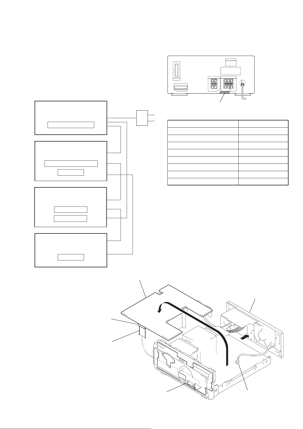
This set is a component of the MHC-S9D.
The MHC-S9D system configuration is as shown below, and therefore it does not operate normally unless all four components are
connected.
In performing the repair, connect all components with the system
cables.
Note: The precaution to the users is described on the label stuck
on the back panel (DVD/video CD/CD player) and in the troubleshooting section in the Operation Manual.
System Configuration:
AC IN
TA
POWER SUPPLY
ST
MASTER & GRAPHIC µcon
DISPLAY
MODEL IDENTIFICATION
– Back Panel –
PART No.
Model PART No.
AEP, UK models 4-232-348-0
Singapore model 4-232-348-4
Saudi Arabia model 4-232-348-5
Australian model 4-232-348-6
Thai model 4-232-348-7
E model 4-232-348-8
Mexican model 4-232-348-9
Korean model 4-233-563-0
[]
[]
[]
[]
[]
[]
[]
[]
DVP
HTC & MB µcon
POWER BLOCK
TC
TC µcon
Turn over the FRONT AMP board with Heat Sink,
SURROUND AMP board and RELAY board connected.
FRONT AMP board
(CN104)
Connect jig (extension cable
J-2501-019-A (except AEP, UK models),
J-2501-087-A (AEP, UK models)
to the FRONT AMP board (CN104)
and PANEL board (CN700).
FRONT AMP BOARD SERVICE POSITION
In checking the FRONT AMP board, prepare jig
(extension cable J-2501-019-A: 1.25 mm Pitch, 25 core, Length
300 mm) (except AEP, UK models)
(extension cable J-2501-087-A: 1.25 mm Pitch, 23 core, Length
300 mm) (AEP, UK models)
(Fig A)
Remove the back panel
(AV) section.
PANEL board (CN700)
Remove the fan motor
connector lead wire.
(Fig A)
3
TA-S9D
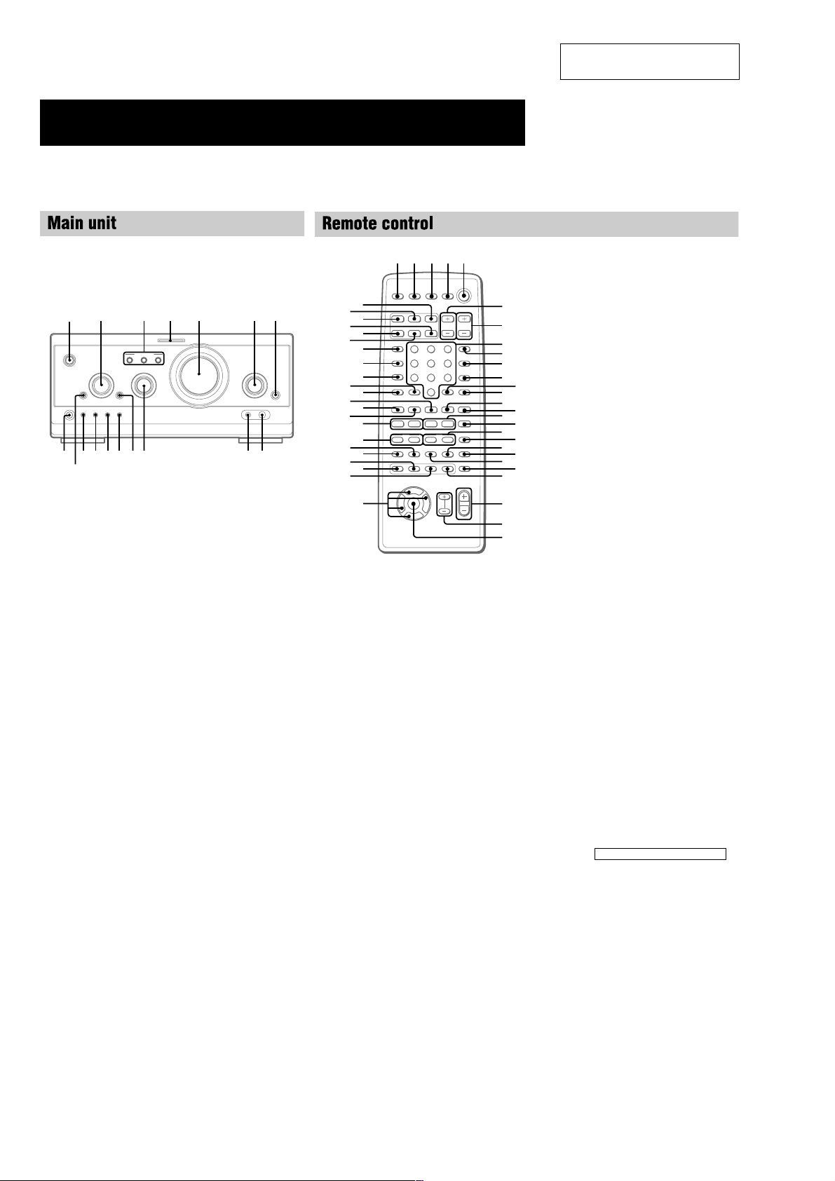
Parts Identification
The items are arranged in alphabetical order.
Refer to the pages indicated in parentheses ( ) for details.
SECTION 2
GENERAL
This section is extracted from
instruction manual.
A/V amplifier
1
A
B C
O
P
p
o
qj
qh
CINEMA STUDIO A–C 3 (49)
DIGITAL 7 (57, 63)
DVD MENU qf (27)
ENTER/O/o/P/p 2
EQ qa (52)
EQ ON/OFF qs (13, 53)
FILE SELECT q; (26, 48, 49,
53)
FUNCTION 6 (12, 13, 25, 27,
28, 36, 45, 46, 55, 57, 62)
MIC jack (Except for European
model) 9 (54)
MIC LEVEL (Except for European
model) 8 (54)
MULTI CHANNEL DECODING
indicator 4 (50)
PHONES jack qj
SET UP qd (14, 16, 51, 53, 54)
SUR qh (51)
TITLE qg (27)
VOLUME 5
@/1 (power) 1 (12, 13, 63)
123 4 5
rl
43 5 62
7
rk
rh
rf
rj
rg
rd
rs
ra
r;
el
ek
ej
eh
eg
ef
ed
89q;qaqsqdqfqg
ea
wl
es
e;
wk
O
V
Bb
v
nN
Mm>.
TtCc
6
7
8
9
q;
qa
qs
qd
qf
x
X
qh
qk
w;
ws
wf
qg
qj
ql
wa
wd
wg
wh
wj
ANGLE es (37)
AUDIO ws (34)
CLEAR qs (22, 29, 30, 36)
CLOCK/TIMER SELECT 3
(47, 56)
CLOCK/TIMER SET 2 (17, 47,
56)
DBFB ra (48)
D.SKIP 9 (26)
DIGITAL rf (57)
DISPLAY rj (17, 31, 32, 43, 54)
DVD DISPLAY wd (18, 19, 30,
32–34, 36–40)
DVD MENU wa (27)
DVD SET UP ql (18, 19, 24, 39)
ENTER wj
EQ ea (52)
EQ ON/OFF wl (53)
FILE SELECT +/– wh (48, 49,
53)
FUNCTION rd (18, 25, 27, 28,
36, 45, 46, 55, 57)
GROOVE rs (48)
KARAOKE PON (Except for
European model) el (54)
MD rh (57)
Numeric buttons 8 (28, 30)
PLAY MODE qa (25, 28, 29, 46)
REPEAT q; (30)
RETURN O qd (27, 39, 40)
SELECT DVD N eh (20, 25,
27, 29, 30)
SET UP wf (14, 16, 51, 53, 54)
SLEEP 1 (55)
SLOW t/T qk (26)
SPECTRUM ANALYZER rk
(54)
STEP c/C ef (26)
SUBTITLE ed (37)
SUR e; (51)
TAPE A nN ek (44)
TAPE B nN qf (44, 45)
TITLE w; (27)
TUNER/BAND ej (42)
TV @/1 4 (13)
TV CH +/– 7 (13)
TV/VIDEO rl (13)
TV VOL +/– 6 (13)
VIDEO rg (57)
VOL +/– wg
BUTTON DESCRIPTIONS
@/1 (power) 5
X (pause) qj
x (stop) qg
m/M (rewind/fast forward),
TUNING –/+ qh
./> (go back/go forward),
PRESET –/+, PREV/NEXT
O/o/P/p wk
>10 r;
eg
4
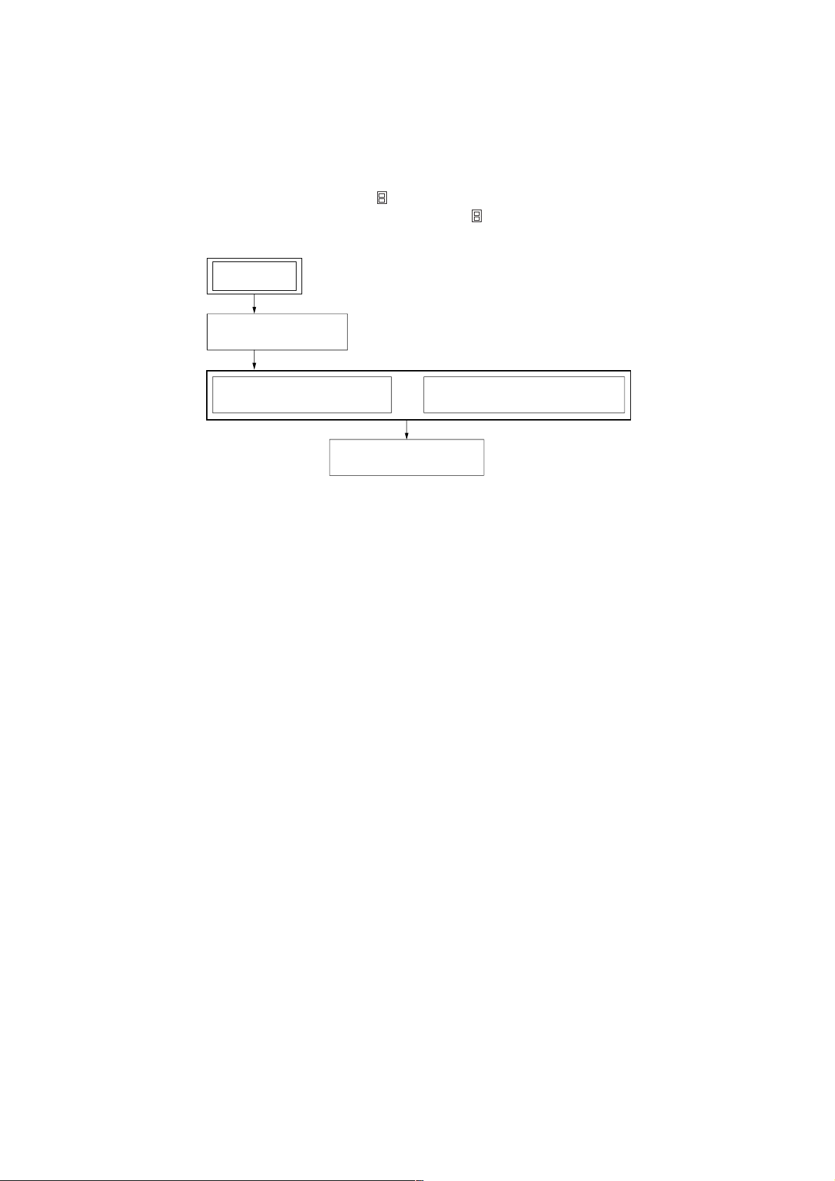
• This set can be disassembled in the order shown below.
3-1. DISASSEMBLY FLOW
Note 1: The process described in can be performed in any order.
Note 2: Without completing the process described in , the next process can not be performed.
SET
3-2. CASE
(Page 6)
TA-S9D
SECTION 3
DISASSEMBLY
3-3. FRONT PANEL SECTION
(Page 6)
3-5. FRONT AMP BOARD
(Page 7)
3-4. BACK PANEL (DVD) SECTION
(Page 7)
5
TA-S9D
)
)
Note: Follow the disassembly procedure in the numerical order given.
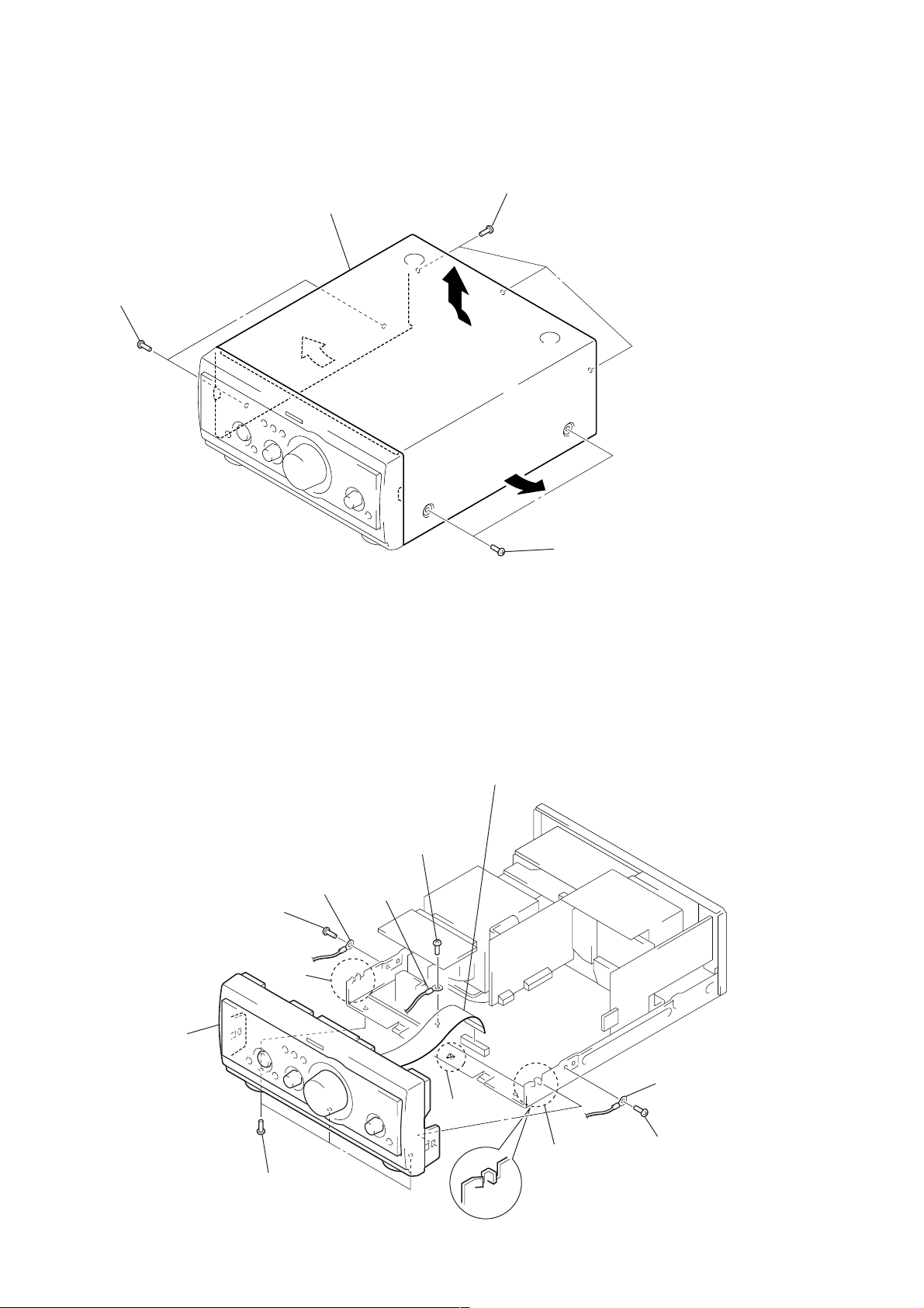
3-2. CASE
4
Remove the case
in the direction of arrow
2
two screws
(case 3 TP2)
3
A
1
three screws
.
A
(BVTT3
3
×
6)
3-3. FRONT PANEL SECTION
2
screw
(BVTP3
5
×
8)
two
claws
3
lug
2
3
screw
(BVTP3
lug
2
two screws
(case 3 TP2
1
wire (flat type) (23 core) (AEP, UK models)
wire (flat type) (25 core) (except AEP, UK models)
(CN104)
×
8)
6
front panel section
6
4
three screws
(BVTP3
3
lug
5
claw
2
5
two claws
×
8)
screw
(BVTP3
×
8
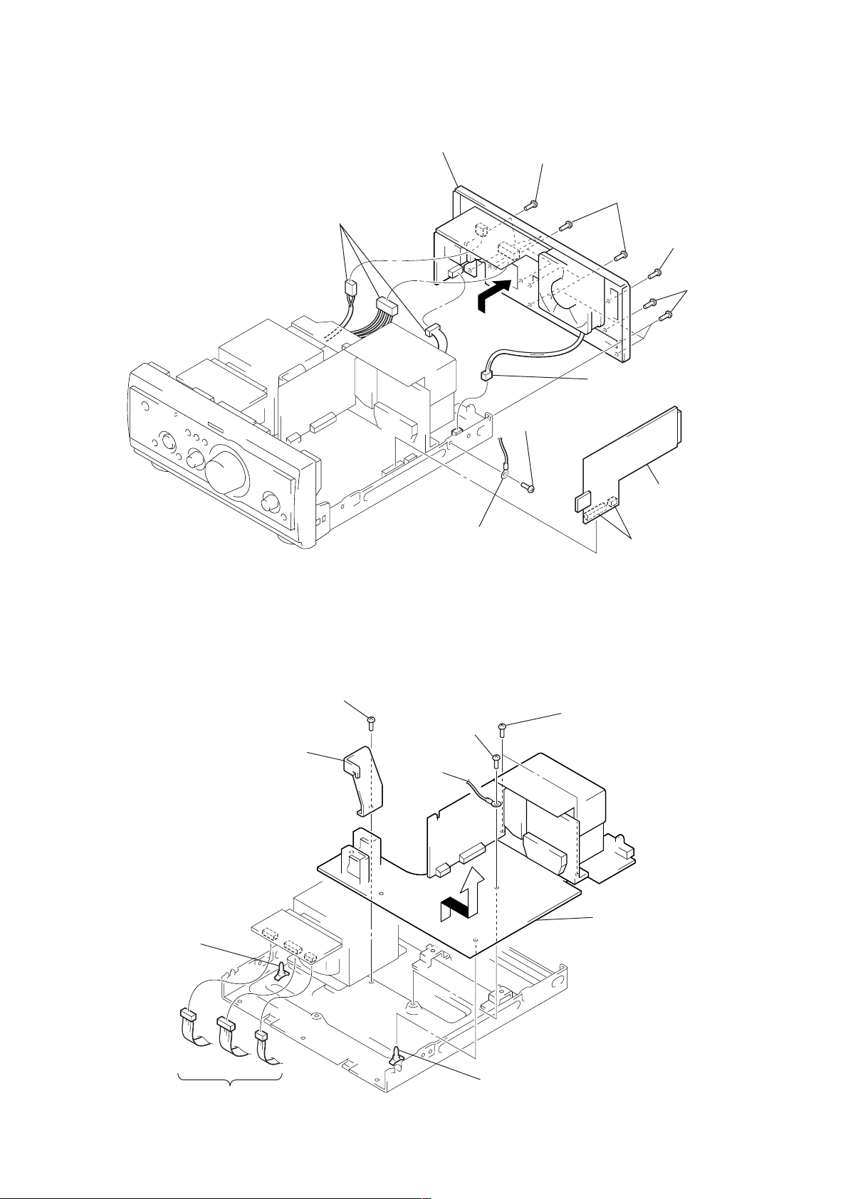
3-4. BACK PANEL (DVD) SECTION
)
d
7
three connectors
(CN901, 902, 903)
8
back panel (DVD) section
6
5
1
screw
(BVTP3 × 8)
three screws
(BVTP3
×
8)
6
connector
(CN105)
5
four screws
(BVTP3
×
8)
1
screw
(BVTP3 × 8)
5
four screws
(BVTP3 × 8
TA-S9D
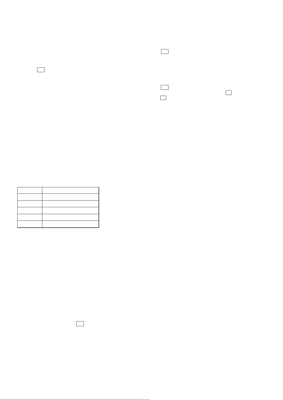
3-5. FRONT AMP BOARD
3
bracket (PWB)
2
screw
(BVTP3
4
RELAY board
2
lug
×
8)
4
5
6
screw
(BVTP3
lug
×
8)
two screws
(BVTT3
3
two connectors
(CN106, 113)
×
8)
7
PC board holder
1
three connector
(CN913, 914, 915)
7
PC board holder
8
Remove the FRONT AMP boar
in the direction of the arrow.
7
TA-S9D
SECTION 4
TEST MODE
Note: Use following buttons in the test mode.
no mark: Button of amplifier unit (TA-S9D)
*1 : Button of tuner unit (ST-S9)
*2 : Button of DVD/video CD/CD player unit (DVP-S9)
[MC Test Mode]
Enter the MC Test Mode
1. Press the I/1 button to turn the power on.
2. While pressing the both [STEREO/MONO] *1 and [CINEMA
STUDIO C] buttons, press the [CINEMA STUDIO A] button.
3. “GROOVE” indication blinks on the fluorescent indicator tube
in the midst of MC test mode.
4. This mode has two modes (mode 1/mode 2).
5. To change the modes, press three buttons in the same manner
as entering this mode (step 2). Each time the step 2 operation
is repeated, it changes modes alternately.
6. To distinguish the mode, turn the [VOLUME] knob clockwise
or counterclockwise. Then display is shown as follows.
Mode 1: only “MIN” or “MAX”
Mode 2: “MIN”, “1 to 30” or “MAX”
AMP Test Mode
In the AMP test mode, it operates as follows.
• [VOLUME] knob is turned, it changes display as follows.
Counterclockwise : VOLUME MIN
Clockwise : VOLUME MAX
• [FILE SELECT] knob is turned, it changes speaker output mode
as follows.
Display of each mode:
Mode No. Display
1 L: L R: R
2 L: SL R: SR
3 L: LSLC R: RSRW
4 L: LSLC R: RSRW
5 L: C R: W
Details of each mode:
Mode 1 : L-CH: front L-CH
R-CH: front R-CH
Mode 2 : L-CH: rear L-CH
R-CH: rear R-CH
Mode 3 : L-CH: front L-CH, rear L-CH, center
R-CH: front R-CH, rear R-CH, sub woofer
(no LFE, “EQ” indication does not light up on the fluorescent
indicator tube of tuner unit)
Mode 4 : L-CH: front L-CH, rear L-CH, center
R-CH: front R-CH, rear R-CH, sub woofer
(LFE on, “EQ” indication lights up on the fluorescent indicator tube of tuner unit)
Mode 5 : L-CH: center
R-CH: sub woofer
[GC Test Mode]
Enter the GC Test Mode
Procedure 1:
1. Press the I/1 button to turn the power on.
2. While pressing the both [STEREO/MONO] *1 and [CINEMA
STUDIO C] buttons, press the [CLOCK/TIMER] *
3. LEDs and fluorescent indicator tube are all turned on of all
units.
Procedure 2:
1. Press the I/1 button to turn the power on.
2. While pressing the both [PLAY MODE] *2 and x *2 buttons,
press the Z (DISC 1) *2 button.
3. LEDs and fluorescent indicator tube are all turned on of all
units.
Version Display Mode
Procedure:
1. Enter the GC test mode.
2. Each time the [TUNER MEMORY] *1 or [DISC 1] *2 button is
pressed, microcomputer or mechanism deck version is displayed of each unit.
3. Press the [TUNING +] *1 or [DISC 3] *2 button to detail is
displayed the version.
Key Check Mode
Procedure:
1. Enter the GC test mode.
2. Press the [TUNING --] *1 or [DISC 2] *2 button to set the key
check mode.
3. In the key check mode, the fluorescent indicator tube displays
“K 0 J 0 V 0”. Each time a button is pressed, “K” value increases. However , once a button is pressed, it is no longer tak en
into account.
“J” value increases like 1, 2, 3 ... if turn the
knob clockwise, or it decreases like 0, 9, 8 ... if turn the JOG
dial counterclockwise.
“V” value increases like 1, 2, 3 ... if turn the [VOLUME] knob
clockwise, or it decreases like 0, 9, 8 ... if turn the JOG dial
counterclockwise.
Releasing the GC Test Mode
T o release from this mode, press three buttons in the same manner
as entering this mode or disconnect the power cord.
1
button.
[FILE SELECT]
Releasing the MC Test Mode
T o release from this mode, press the
power cord.
8
I/1 button or disconnect the

MEMO
TA-S9D
9
 Loading...