

Sony STRW-777 Service manual
STR-W777
MICROFILM
SERVICE MANUAL
STR-W777 is the tuner and amplifier
section in MHC-W777AV.
SPECIFICATIONS
Amplifier section
(Saudi Arabia, Singapore, Malaysia,Thai, Australian)
The following measured at AC 230V 50/60 Hz
DIN power output (Rated) (FRONT)
95 + 95W (6 Ω at 1kHz DIN)
Continuous RMS power output (Reference)
FRONT SPEAKER: 110 + 110W
(6 Ω at 1kHz, 10% THD)
CENTER SPEAKER: 55W
(8 Ω at 1kHz, 10% THD)
REAR SPEAKER: 35 + 35W
(8 Ω at 1kHz, 10% THD)
The following measured at AC 120, 220, 240V 50/60Hz
DIN power output (Rated) (FRONT)
100 + 100W (6 Ω at 1kHz DIN)
Continuous RMS power output (Reference)
FRONT SPEAKER: 120 + 120 W
(6 Ω at 1kHz, 10% THD)
CENTER SPEAKER: 60W
(8 Ω at 1kHz, 10% THD)
REAR SPEAKER: 40 + 40W
(8 Ω at 1kHz 10% THD)
Peak music power output 2400W
AEP Model
UK Model
E Model
Australian Model
(AEP, UK, East European, CIS)
DIN power output (Rated) (FRONT)
80 + 80W (6 Ω at 1kHz DIN)
Continuous RMS power output (Reference)
FRONT SPEAKER: 100 + 100W
(6 Ω at 1kHz, 10% THD)
CENTER SPEAKER: 60W
(8 Ω at 1kHz, 10% THD)
REAR SPEAKER: 35 + 35W
(8 Ω at 1kHz, 10% THD)
Music power output (Reference)
FRONT SPEAKER: 190 + 190 W
(6 Ω at 1kHz, 10% THD)
CENTER SPEAKER: 90W
(8 Ω at 1kHz, 10% THD)
REAR SPEAKER: 55 + 55W
(8 Ω at 1kHz, 10% THD)
Inputs MD/VIDEO 1 IN (phone jacks): voltage
450/250mV, impedance 47kΩ
AV INPUT AUDIO (phone jacks): voltage
250mV, impedance 47kΩ
MIX MIC (phone jack): sensitivity 1mV,
impedance 10kΩ
— Continued on next page —
FM STEREO/FM-AM RECEIVER

Output MD/VIDEO 1 OUT (phono jacks): voltage
450/250mV, impedance 1kΩ
PHONES (stereo phone jack): accepts
headphones of 8Ω or more.
FRONT SPEAKER:
accepts impedance of 6 to 16Ω
CENTER SPEAKER:
accepts impedance of 8 to 16Ω
REAR SPEAKER:
accepts impedance of 8 to 16Ω
SUPER WOOFER:
Voltage 1V, impedance 1kΩ
Video section
Inputs AV INPUT VIDEO (phone jack): 1Vp-p, 75Ω
Outputs MONITOR OUT (phone jack): 1Vp-p, 75Ω
AM tuner section
Tuning range
Australian model: 531 – 1,602kHz (with the AM tuning interval
set at 9kHz)
530 – 1,710kHz (with the AM tuning interval
set at 10kHz)
Other models: MW: 531 – 1,602kHz (with the MW tuning
interval set at 9kHz)
530 – 1,710kHz (with the MW tuning interval
set at 10kHz)
SW: 5.95 – 17.90MHz (with the SW tuning
interval set at 5kHz)
LW: 153 – 279kHz (with the interval set at
3kHz)
Intermediate frequency 450kHz
Antenna AM loop antenna External antenna terminal
Tuner section
FM stereo, FM/AM superheterodyne tuner
FM tuner section
Tuning range
3 band type model 87.5 – 108.0MHz (50kHz step)
4 band type model 65.0 – 74.0MHz (10kHz step)
87.5 – 108.0MHz (50kHz step)
Aerial FM lead aerial
Aerial terminals 75Ω unbalanced
Intermediate frequency 10.7MHz
UKV tuner section (4 band type model only)
Tuning range 65.0 – 74.0MHz (10kHz step)
Polar Stereo
General
Power requirements
Australian models: 240V AC, 50/60Hz
AEP, UK, East European, CIS models:
230V AC, 50/60Hz
Other models: 120V or 220V or 230 – 240, 50/60Hz
Adjustable with voltage selector
Power consumption 270W (AEP, UK, East European, CIS models)
300W (Other models)
Dimensions (w/h/d) Approx. 288 × 205 × 375mm
Mass Approx. 8.8kg
Supplied accessories: AM loop antenna (1)
Remote RM-SR77 (1)
Size AA (R6) batteries (2)
FM lead antenna (1)
Speaker cords (5)
Front speaker pads (8)
Design and specifications are subject to change without notice.
— 2 —

TABLE OF CONTENTS
1. GENERAL ........................................................................... 4
2. DISASSEMBLY
• Sliding Panel Assembly......................................................5
3. SERVICE MODE ..............................................................6
4. ELECTRICAL ADJUSTMENT ................................... 11
MODEL IDENTIFICATION
— BACK PANEL —
LABEL MODEL NUMBER
No.
5. DIAGRAMS
5-1. Circuit Boards Location ··················································· 12
5-2. Block Diagrams
• Tuner Section (AEP, UK model)···································· 13
• Tuner Section (East European, CIS model) ··················· 15
• Main Section ·································································· 17
• Power Section ································································ 19
5-3. Schematic Diagram
–Tuner (AEP, UK model) Section – ································· 23
5-4. Printed Wiring Board
–Tuner (AEP, UK model) Section – ································· 25
5-5. Printed Wiring Board
–Tuner (East European, CIS model) Section – ················ 26
5-6. Schematic Diagram
–Tuner (East European, CIS model) Section – ················ 27
5-7. Printed Wiring Board – Main Section – ··························· 29
5-8. Schematic Diagram – Main (1/2) Section – ····················· 31
5-9. Schematic Diagram – Main (2/2) Section – ····················· 33
5-10. Schematic Diagram – AV/Mic Section – ·························· 35
5-11. Printed Wiring Board – AV/Mic Section – ······················· 36
5-12. Schematic Diagram – Power Amp Section – ··················· 37
5-13. Printed Wiring Board – Power Amp Section –················· 39
5-14. Schematic Diagram – Display Section – ··························41
5-15. Printed Wiring Board – Display Section – ······················· 43
5-16. Schematic Diagram – Sliding Panel Section –·················45
5-17. Printed Wiring Board – Sliding Panel Section – ··············47
5-18. Schematic Diagram – Surround Section – ······················· 49
5-19. Printed Wiring Board – Surround Section –····················· 51
5-20. Printed Wiring Board – Trans Section –··························· 53
5-21. Schematic Diagram – Trans Section – ····························· 55
5-22. IC Block Diagrams···························································56
5-23. IC Pin Function ································································ 60
MODEL PART No.
Saudi Arabia, Singapore, Malaysia 4-900-848-2π
Thai, Australian 4-900-848-3π
AEP, UK, East European, CIS 4-900-848-4π
6. EXPLODED VIEWS
6-1. Case and Sliding Panel Section ........................................ 63
6-2. Front Panel Section .......................................................... 64
6-3. Slide Mechanism Section ................................................. 65
6-4. Circuit Boards and Back Panel Section............................ 66
7. ELECTRICAL PARTS LIST ........................................67
SAFETY-RELATED COMPONENT WARNING !!
COMPONENTS IDENTIFIED BY MARK ! OR DOTTED LINE
WITH MARK ! ON THE SCHEMATIC DIAGRAMS AND IN
THE PARTS LIST ARE CRITICAL TO SAFE OPERATION.
REPLACE THESE COMPONENTS WITH SONY PARTS
WHOSE PART NUMBERS APPEAR AS SHOWN IN THIS
MANUAL OR IN SUPPLEMENTS PUBLISHED BY SONY.
— 3 —
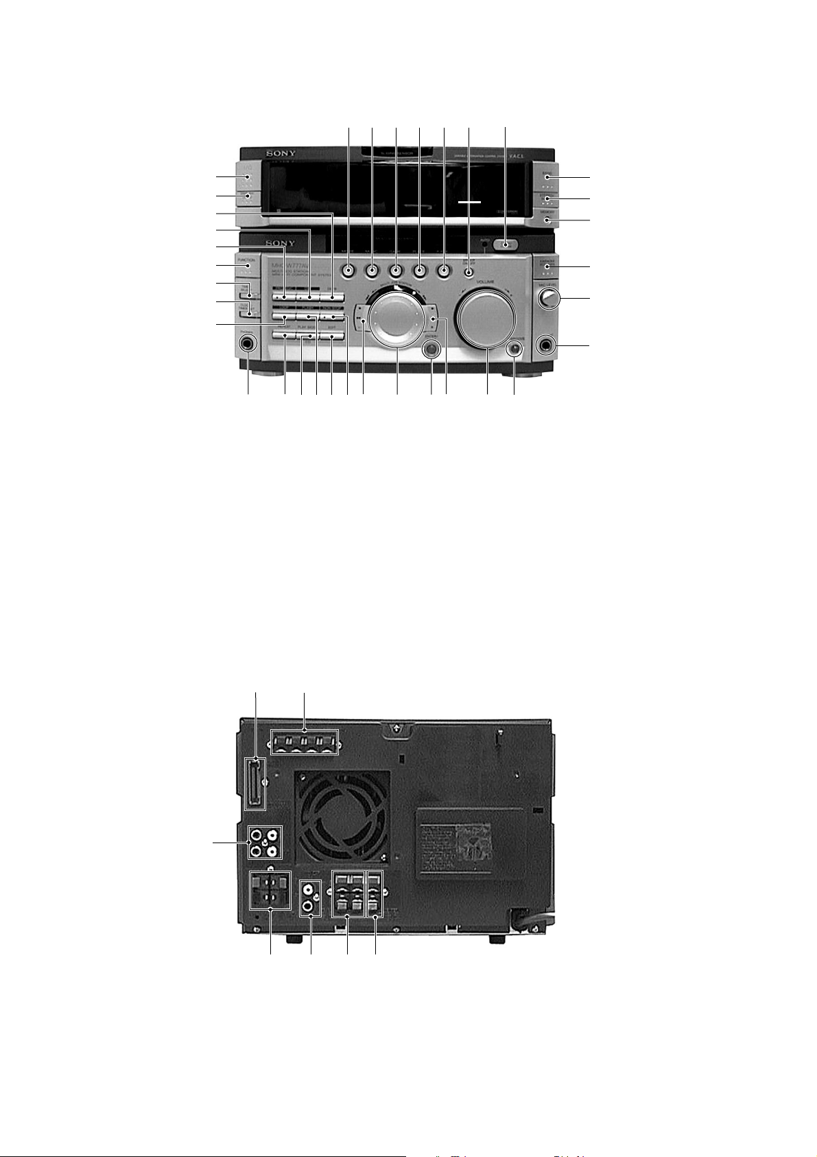
Front Panel
SECTION 1
GENERAL
1 2 3 4 5 6
7
#¢
#£
#™
#¡
#º
@ª
@•
@¶
@§
@∞
1 MOVIE button
2 MUSIC button
3 GAME button
4 PLACE button
5 P FILE button
6 EFFECT ON/OFF button
7 OPEN/CLOSE button
8 TUNER BAND button
9 STEREO/MONO button
!º MEMORY button
!¡ KARAOKE PON/MIX button
!™ MIC LEVEL dial
@™
@¢
@£
@¡
@º
!ª
!•
!£ MIX MIC jack
!¢ GROOVE button
!∞ VOLUME dial
!§ ) + button
!¶ ENTER/NEXT button
!• MULTI JOG STATION dial
!ª 0 – button
@º NON-STOP button
@¡ EDIT button
@™ FLASH button
@£ PLAY MODE button
@¢ REPEAT button
!¶
!§
8
9
!º
!¡
!™
!£
!∞
!¢
@∞ PHONES jack
@§ LOOP button
@¶ CLOCK/TIMER SET button
@• TIMER SELECT button
@ª FUNCTION button
#º PROLOGIC button
#¡ DSP button
#™ DBFB button
#£ DISPLAY/DEMO button
#¢ I/u (POWER) button
Rear Panel
7
1
2
4
6
5
3
1 SYSTEM CONTROL jack
2 ANTENNA terminal
3 CENTER SPEAKER terminal
4 REAR SPEAKER terminal
5 MONITOR OUT jack
6 FRONT SPEAKER terminal
7 MD/VIDEO 1 jack
— 4 —
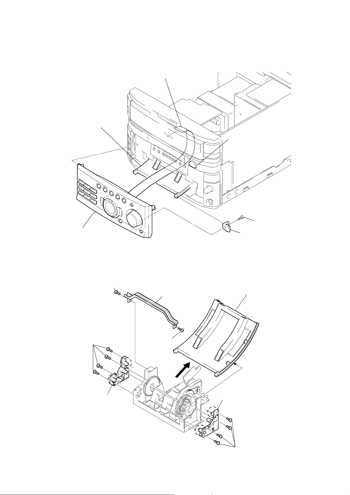
SECTION 2
DISASSEMBLY
Note: Follow the disassembly procedure in the numerical order given.
2-1. SLIDING PANEL ASSEMBLY
4
Flat type cable (19 core)
Slide mechanism
1
Push the OPEN/CLOSE button to
open the Sliding panel assembly.
5
Sliding panel assembly
• NOTE FOR INSTALLATION (LEVEL SLIDER)
1
Screw (BVTP2.6x8)
4
Four screw
(BVTP2.6x8)
b
2
(BVTP2.6x8)
a
3
Top bracket
Screw
2
Screw (BVTP 3x8)
3
Holder level
8
Remove the Level slider direction of arrow.
5
Holder (L) assembly
NOTE :
Attach in the reverse order, but make sure the rollers (a, b) of the
holder (L) assembly and holder (R) assembly fit into the grooves of
the level slider.
— 5 —
b
7
Holder (R) assembly
a
Four screw (BVTP2.6x8)
6

SECTION 3
SERVICE MODE
Connections and Operations When Used Alone
Normally, use the unit connected to the HTC-W555 as follows.
Basically, when servicing the unit, connect the unit as follows.
UNIT
SYSTEM CONTROL 17P
AC IN
Even when not connected to the HTC-W555, the unit can operate alone as it mounts a power supply (some functions will however not be
available).
MC Cold Reset
• The cold reset clears all data including preset data stored in the RAM to initial conditions. Execute this mode when returning the set to the
customer.
Procedure:
1. Press three buttons EDIT , ENTER/NEXT , and DISPLAY/DEMO simultaneously.
2. The fluorescent indicator tube becomes blink instantaneously, and the set is reset.
CD Delivery Mode (This mode can be used only when the HTC-W555 is connected.)
• This mode moves the pick-up to the position durable to vibration. Use this mode when returning the set to the customer after repair.
Procedure:
1. Press 1/u button to turn the set ON.
2. Press LOOP button and 1/u button simultaneously.
3. A message “LOCK” is displayed on the fluorescent indicator tube, and the CD delivery mode is set.
MC Hot Reset
• This mode resets the set with the preset data kept stored in the memory. The hot reset mode functions same as if the power cord is plugged
in and out.
Procedure:
1. Press three buttons REPEAT , ENTER/NEXT , and DISPLAY/DEMO simultaneously.
2. The fluorescent indicator tube becomes blink instantaneously, and the set is reset.
HTC-W555
Sled Servo Mode (This mode can be used only when the HTC-W555 is connected.)
• This mode can run the CD sled motor freely. Use this mode, for instance, when cleaning the pick-up.
Procedure:
1. Select the function “CD”.
2. Press three buttons FLASH , ENTER/NEXT , and KARAOKE PON/MIX simultaneously.
3. The Sled Servo mode is selected, if “CD” is blinking on the fluorescent indicator tube.
4. With the CD in stop status, press ) + button move the pick-up to outside track, or – 0 button to inside track.
5. To exit from this mode, perform as follows:
1) Move the pick-up to the most inside track.
2) Press three buttons in the same manner as step 2.
Note:
• Always move the pick-up to most inside track when exiting from this mode. Otherwise, a disc will not be unloaded.
• Do not run the sled motor excessively, otherwise the gear can be chipped.
Change-over of FUNCTION Name
• The FUNCTION name of external input terminal can be changed over to VIDEO 1 or MD. With the FUNCTION selected to “MD”, about
5dB mute is applied to the input gain.
Procedure:
1. Press 1/u button to turn the set OFF.
2. Press 1/u button together with FUNCTION button, and the power is turned on, the display of fluorescent indicator tube changes to
“MD” or “VIDEO 1” instantaneously, and thus the FUNCTION is changed over.
Change-over of AM Tuner Step between 9kHz and 10kHz
• A step of AM channels can be changed over between 9kHz and 10kHz.
Procedure:
1. Press 1/u button to turn the set ON.
2. Select the function “TUNER”, and press TUNER/BAND button to select the BAND “MW”.
3. Press 1/u button to turn the set OFF.
4. Press ENTER/NEXT and 1/u buttons simultaneously, and the display of fluorescent indicator tube changes to “MW step 10” or
“MW step 9”, and thus the channel step is changed over.
— 6 —

LED and Fluorescent Indicator Tube All Lit, Key Check Mode (Do not connect the HTC-W555.)
Procedure:
1. Press 1/u button to turn the set ON.
2. Press the OPEN/CLOSE button to open the sliding panel.
3. Press three buttons DELAY , ENTER/NEXT , and DISPLAY/DEMO simultaneously.
4. LEDs and fluorescent indicator tube are all turned on. Each time the MOVIE button is pressed, the fluorescent indicator tube lights up
as follows:
lights up completely n lights up partially 1 n lights up partially 2 n lights up completely.
5. Press GAME button, and the key check mode is activated.
6. In the key check mode, the fluorescent indicator tube displays “K @@ V0 J0”. Each time a button is pressed, “K”value decreases.
However, once a button is pressed, it is no longer taken into account. (@@ means the total of buttons)
“J” Value increases like 1, 2, 3 ... if rotating JOG knob in “+” direction, or it decreases like 0, 9, 8 ... if rotating in “-” direction.
“V” Value increases like 1, 2, 3 ... if rotating VOLUME knob in “+” direction, or it decreases like 0, 9, 8 ... if rotating in “-” direction.
7. Pressing all buttons lights up the fluorescent indicator tube completely.
8. To exit from this mode, press three buttons EDIT , ENTER/NEXT and DISPLAY/DEMO simultaneously. (COLD RESET)
9. To exit from this mode, press three buttons in the same manner as step 1, or disconnect the power cord.
CD, TAPE Deck Aging Mode (This mode can be used only when the HTC-W555 is connected.)
This mode can be used for checking the operations of the CD player and tape deck.
• When problems occur;
Aging stops, and the stopped state is displayed on the fluorescent indicator tube.
• When no problems;
Aging continues.
Preparations:
• Set the CD on the DISC1 tray.
• Insert a commercially available tape for recording (tapes which contents can be erased, etc.) in decks A and B.
Setting the aging mode:
Press the PLAY MODE button, ENTER/NEXT button, and STEREO/MONO button together.
When the aging mode is set, the CD roulette mark blinks. To exit the mode, press the 1/u button and turn OFF the power.
Sequence:
The aging mode is executed in the following sequence.
If the function is set to “CD” when the aging mode is set, aging is performed starting from the CD player. When set to “TAPE A” or “TAPE
B”, aging is started from deck A.
If the function is set to others, aging will not be started until the function is switched to CD or TAPE.
Aging of CD player (12 minutes)
Aging of deck A
Aging of deck B
12 minutes
Display of status:
• The aging status is displayed on the fluorescent indicator tube.
• Normally, the CD player displays the remaining aging time. But if operations ended abnormally, it displays the cause.
• During the aging of the tape deck, the operations performed will be displayed. If operations ended abnormally, this will be displayed at the
fluorescent display tube.
CD Player
• During normal operations:
Display of fluorescent indicator tube
**1-@@
**: Displays “CD” and the remaining aging time (minutes) alternately. The remaining aging time is counted down from 12.
@@: Track number being accessed.
— 7 —

• When operations end abnormally:
Display of fluorescent display tube
Display
NO DISC ERR
FOCUS1 ERR
FOCUS2 ERR
GFS ERR
FBIAS ERR
SENSOR ERR
TABLE ERR
TRAY ERR
Tape Deck
Display of Operations
TAPE A AG-1
TAPE A AG-2
TAPE A AG-3
TAPE A AG-4
TAPE A AG-5
TAPE B AG-1
TAPE B AG-2
TAPE B AG-3
TAPE B AG-4
TAPE B AG-5
Main Cause
DISC 1 is NO DISC from the beginning
Focus is not imposed properly
The focus deviated several times after the disc rotated normally
GFS ERROR
Error during focus bias adjustment
DISC 1 was found to be NO DISC by the disc sensor
The table did not rotate normally
The tray containing the BD did not operate normally
Operation
TAPE A REW
TAPE A FWD
TAPE A FF
TAPE A REV
TAPE A REW
TAPE B REW
TAPE B FWD
TAPE B FF
TAPE B REV
TAPE B REW
Shutoff
2 minute playback
20 seconds or shutoff
2 minutes playback
Shutoff
Shutoff
2 minute playback
20 seconds or shutoff
2 minute playback
Shutoff
Timing of Ending
Operations during aging
• Operations are performed in the following sequence during aging.
<CD player>
1. The CD tray rotates and disc 1 is selected.
2. Chucking is performed.
3. TOC is read.
4. Track 1 played back for 2 seconds.
5. The last track is played back for 2 seconds.
6. 1 to 5 is repeated.
7. After 12 minutes of aging, aging is switched to the tape deck.
<Tape Deck>
1. The tape in deck A is rewound to the head.
2. The FWD side is played back for 2 minutes.
3. The tape is fast forwarded (FF) for 20 seconds. The following procedure is performed when the tape end is reached before the 20
seconds.
4. The REV side is played back for 2 minutes.
5. The tape is rewound to the head (REW).
6. The tape in deck B is rewound to the head.
7. The FWD side is played back for 2 minutes.
8. The tape is fast forwarded (FF) for 20 seconds. The following procedure is performed when the tape end is reached before the 20
seconds.
9. The REV side is played back for 2 minutes.
10. The tape is rewound to the head (REW).
11. Aging is switched to the CD player.
— 8 —

PANEL Aging Mode
This mode is used for opening and closing the sliding panel continuously.
Setting the aging mode :
With the set at standby condition, press FLASH button, ENTER/NEXT button and STEREO/MONO button together.
The aging will start and sliding panel will follow aging sequence as described below.
• When problems occur ;
Aging stops and “AGING ERROR” is displayed on the fluorescent indicator tube.
• When no problems;
Aging is carried out repeatedly. After 65000 times, “AGING STOP” is displayed and aging stops.
Aging Sequence
Stops for one second in the opened state
Panel open Panel close
n
Counts up
n n
Stops for one second in the closed state
Each time the DISPLAY/DEMO button is pressed, the display switches as follows.
Aging @@@@@ (No. of agings carried out)
OP Max @.@@ (Maximum time taken for OPEN:In seconds)
OP Min @.@@ (Minimum time taken for OPEN:In seconds)
CL Max @.@@ (Maximum time taken for CLOSE:In seconds)
CL Min @.@@ (Minimum time taken for CLOSE:In seconds)
— 9 —
SECTION 4
ELECTRICAL ADJUSTMENT
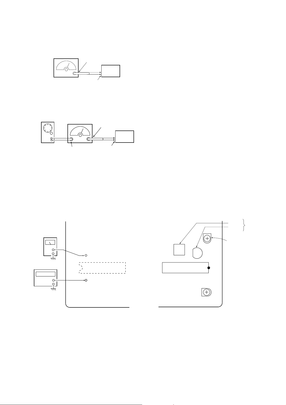
TUNER SECTION 0dB=1µV
Note 1: As a front-end (FE1) is difficult to repair if faulty, replace
it with new one.
Note 2: No adjustment is needed for a tuner pack except for AEP,
UK, East European, CIS models.
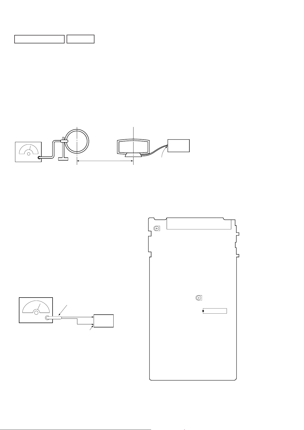
AM Tuned Level Adjustment
(AEP, UK, East European, CIS model)
Note: FM Tuned Level Adjustment should be performed after this
AM Tuned Level Adjustment.
Setting:
Band: MW
loop antenna
(Supplied accessories)
µ
V/m) = SSG output level dB (µV/m) –26dB.
AM RF SSG
30% amplitude
modulation by
400Hz signal
loop antenna
60cm
Field strength dB (
set
AM antenna
terminal (TM1)
Modulation: 999 kHz (at 9 kHz step)
1,050 kHz (at 10 kHz step)
Procedure:
1. Set the output of SSG so that the input level of the set becomes
55 dB.
2. Tune the set to 999 kHz or 1,050 kHz.
3. Adjust R V41 to the point (moment) when the TUNED indicator
will change from going off to going on.
Adjustment Location: TCB board
FM Tuned Level Adjustment
(AEP, UK, East European, CIS model)
Note: This adjustment should be performed after the AM Tuned
Level Adjustment.
Setting:
Band: FM
FM RF SSG
75
Ω
coaxial
set
Carrier frequency: 98MHz
Modulation: AUDIO 1kHz, 75kHz
Output level: 25dB (at 75
deviation (100%)
Ω
FM ANTENNA terminal (TM1)
open)
Adjustment Location
[TCB BOARD] (Component Side)
TM1
RV41
AM Tuned Level
RV42
FM Tuned
Level
IC21
Procedure:
1. Supply a 25 dB 98 MHz signal from the ANTENNA terminal.
2. Tune the set to 98 MHz.
3. Adjust R V42 to the point (moment) when the TUNED indicator
will change from going off to going on.
Adjustment Location: TCB board
— 10 —
FM Polar Adjustment (East European, CIS model)
Connection 1 :
FM RF SSG
Carrier frequency: 69 MHz
Output level: 1 mV (60 dB
Modulation: AUDIO 1 kHz, 10 kHz deviation
75
Ω
coaxial
FM antenna
terminal (75
set
Ω
)
µ
) (at 75 Ω open)
Connection 2 :
AF OSC
FM RF SSG
75
Ω
coaxial
set
Procedure :
1. Set the modulation of FM RF SSG to AUDIO 1 kHz, 10 kHz
deviation according to “Connection 1”.
2. Tune the set to 69 MHz.
3. Adjust the RV1702 so that the reading of frequency counter
connected to TP1702 (VCO) becomes within 31.25 kHz ± 0.05
kHz. (VCO adjustment)
4. Then record the reading of the level meter connected to TP1701.
5. Set the modulation of FM RF SSG to AUDIO 31.25 kHz, 10
kHz deviation according to “Connection 2”.
6. Tune the set to 69 MHz.
7. Set the CT1701 to be mechanical center.
8. Adjust the L1701 so that the reading of the level meter
connected to TP1701 (FILTER) becomes maximum.
Then adjust the CT1701 so that the reading of the level meter
connected to TP1701 (FILTER) becomes maximum. (SUB
CARRIER PEAK Adjustment)
9. Adjust the RV1701 so that the level at the moment becomes 14
dB higher value than the level recorded in step 4. (SUB
CARRIER LEVEL Adjustment)
Audio 31.25 kHz
Carrier frequency: 69 MHz
Output level: 1 mV (60 dB
Modulation: AUDIO 31.25 kHz, 10 kHz deviation
external
modulation
terminal
µ
) (at 75 Ω open)
(EXTERNAL MODULATION)
Adjustment Location:
[TCB BOARD] (Conductor Side)
level meter
TP1701
(FILTER)
frequency counter
TP1702
(VCO)
IC1701
FM antenna
terminal (75
Ω
)
Adjustment Location: TCB board
[TCB BOARD] (Component Side)
L1701
CT1701
RV1701
Sub Carrier
Level
IC1701
RV1702
VCO
Sub Carrier Peak
— 11 —
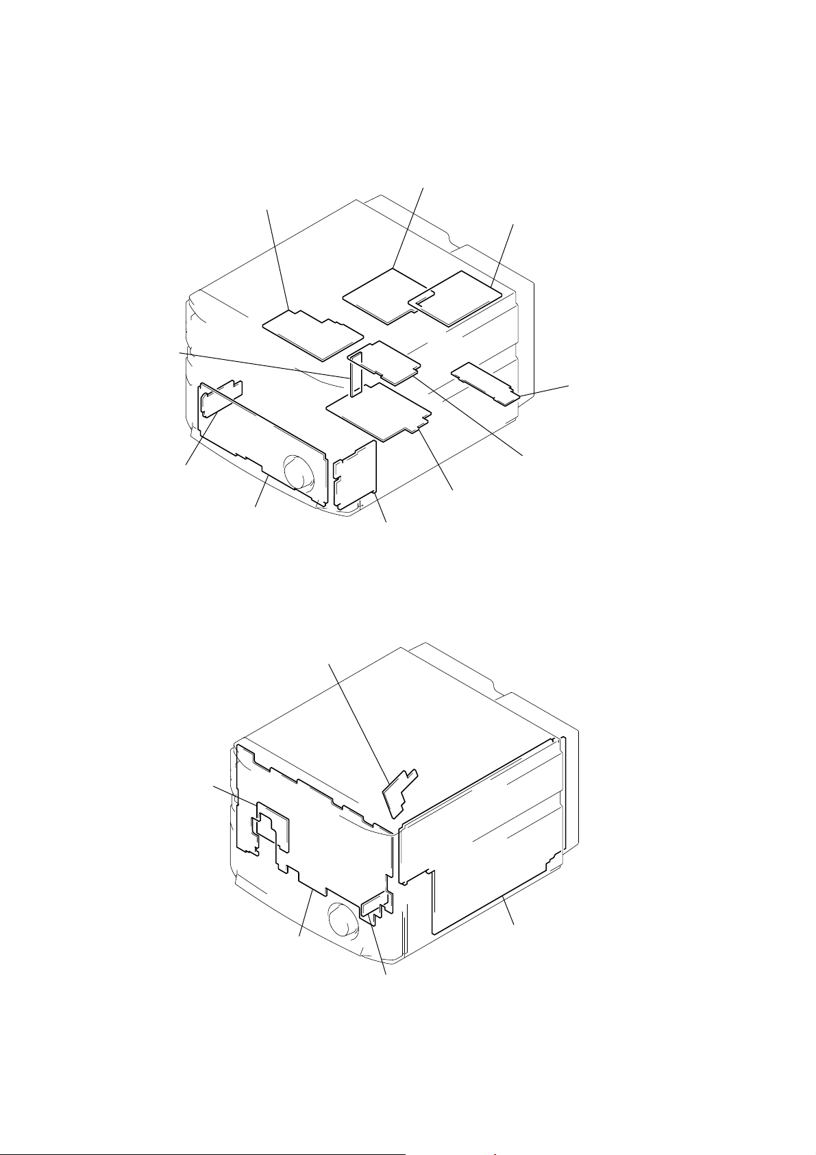
5-1. CIRCUIT BOARDS LOCATION
d
SECTION 5
DIAGRAMS
CONNECTOR board
HEADPHONE board
SECONDARY board
LOADING PANEL board
PRIMARY board
POWER AMP board
MIC / ECHO board
ENCAPSULATED COMPONENT
(EA, SP, MY, TH, AUS)
TCB board (AEP, UK, EE, CIS)
SURR SPK boar
SURR AMP board
FRONT AV board
MOTOR board
PANEL board
DETECTOR board
MAIN board
• Abbreviation
EE : East European
EA : Saudi Arabia
SP : Singapore
MY : Malaysia
AUS : Australian
TH : Thai
— 12 —
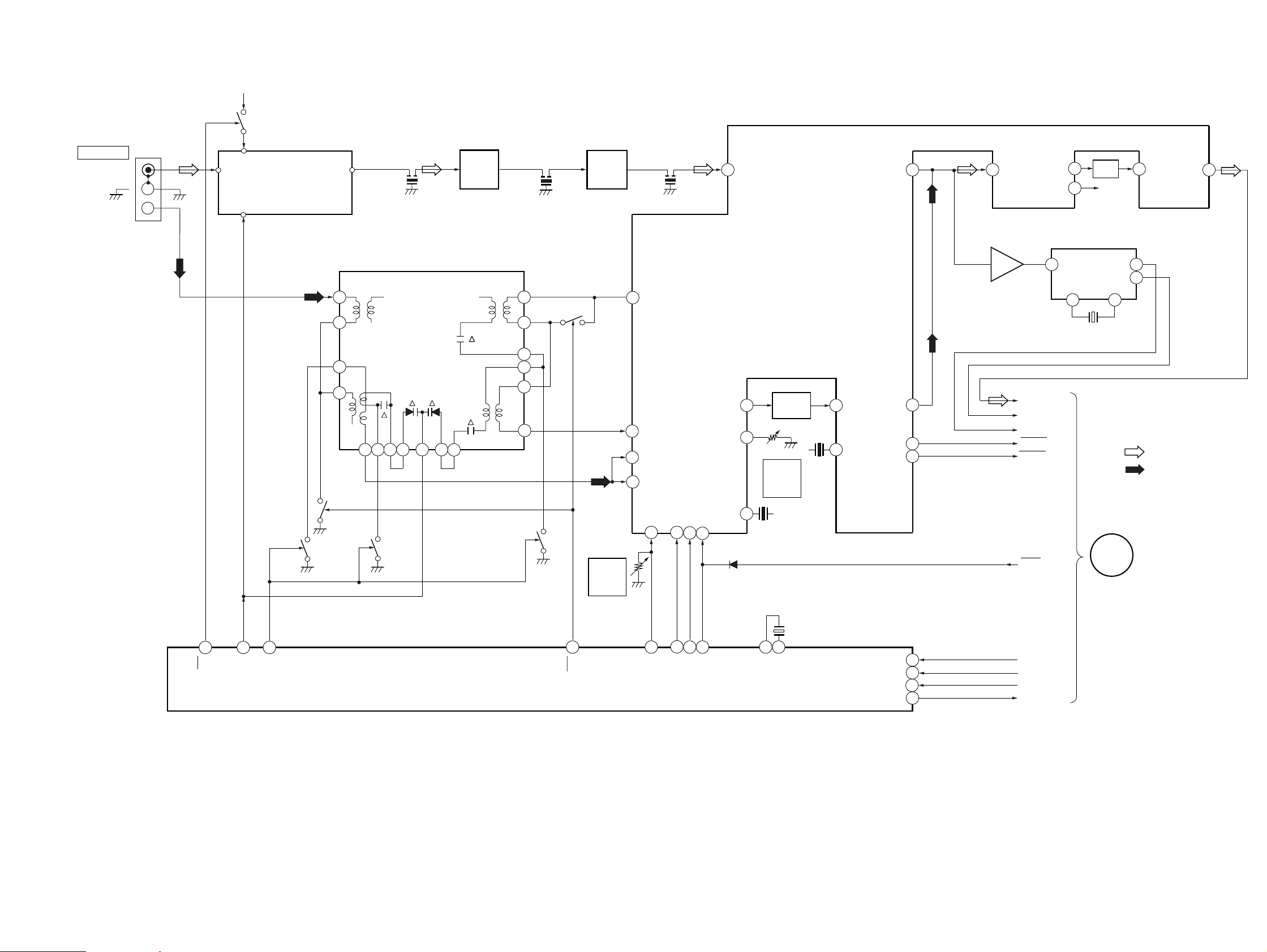
5-2. BLOCK DIAGRAM – TUNER SECTION – (AEP, UK model)
ST +10V
Q5
TM1
ANTENNA
FM 75Ω
COAXIAL
AM
ANT IN
VT
FE1
FM FRONT END
IF OUT
10.7MHz
CF1
IF AMP
Q1, 2
CF2
10.7MHz
IF AMP
Q3, 4
CF3
10.7MHz
1 FM IN
FM DET OUT
23 22
MPX IN
OUT L
OUT R
STR-W777
21
LPF
20
RCH
19
AMP IN L
AMP
OUT
L
17
Q13
MW
SW
6
5
3
2
26 25 24 23 22 21
Q14
LW SW
FE2
MW/LW FRONTEND
Q12
MW
SW
FM/AM MPX
IC41
12
13
14
15
16
17
20
LW SW
Q11
MW
SW
Q9
RV42
FM
TUNED
LEVEL
28
29
26
27
REG
AM OSC
FM AFC
AM RF IN
FM SD
ADJ
OSC.BUFF
30 14
VCO STOP
AM/FM
15
AM MIX
IF BUFF
13
AM
SD
ADJ
AM
MUTE
SD
D41
2
12
10
RV41
X42
450kHz
AM IF
IFT41
AM
TUNED
LEVEL
X41
10.7MHz
4
9
AM IF
FM
DET
AM
DET
OUT
STEREO
TUNED
24
7
6
IC1751
57
ST L
RDS INT
RDS DATA
STEREO
TUNED
MUTE
RDS DECODER
4
13 14
4.332MHz
IC1752
2
16
X1751
• R CH: Same as L ch
• SIGNAL PATH
: FM
: MW
A
MAIN
SECTION
(Page 17)
X21
2
1710
9
FM
16
VT1
MW
PLL
IC21
11
MW
7
AM OSC
FM
VCO STOP
1214
FM/AM IF
1 24
XIN
4.5MHz
XOUT
3 ST-CE
CE
4
DI
5
CL
DO
6
COM-DIN
COM-CLK
COM-DATA
— 13 — — 14 —
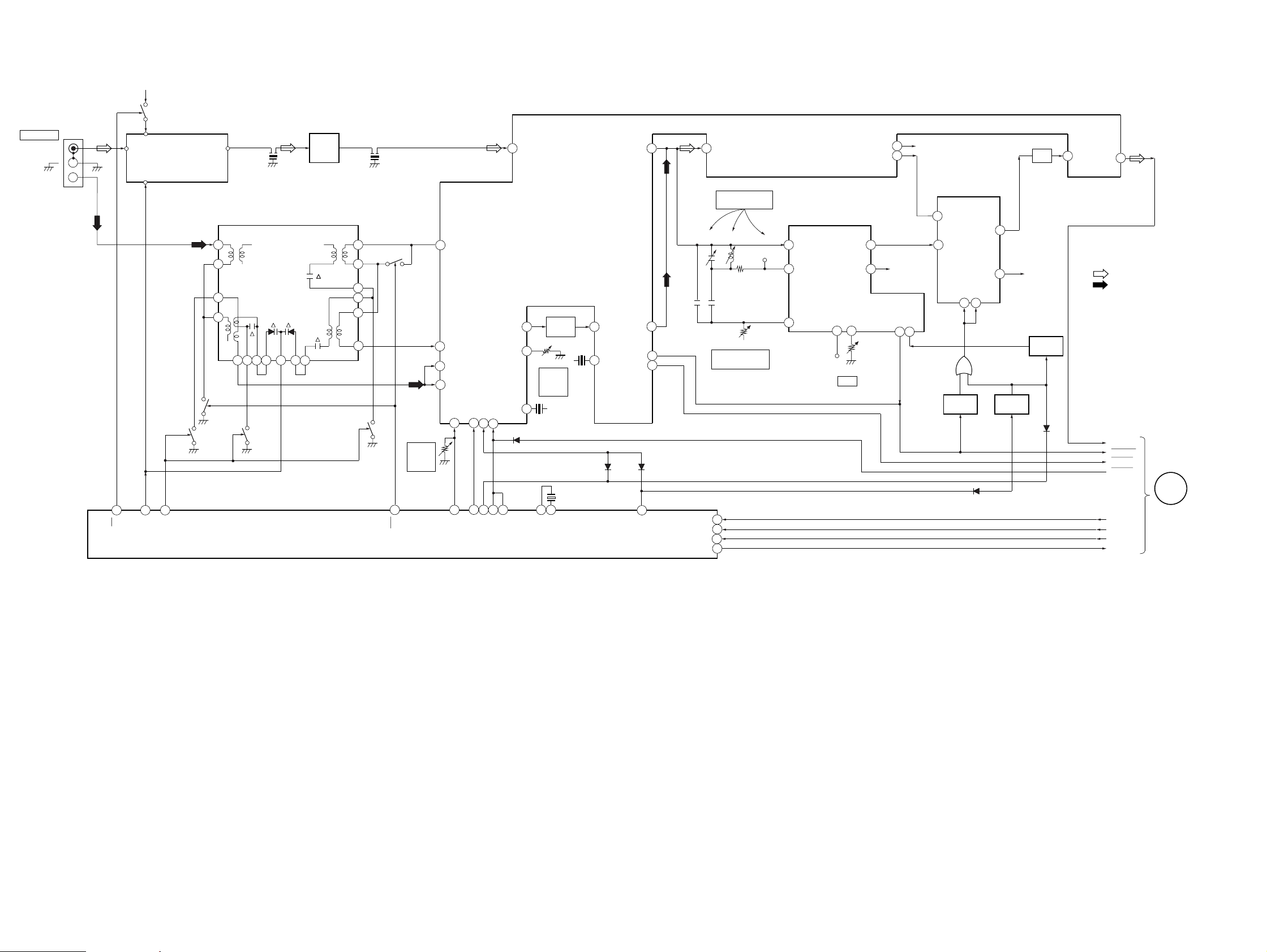
STR-W777
– TUNER SECTION – (East European, CIS model)
ST +10V
TM1
ANTENNA
FM 75Ω
COAXIAL
AM
ANT IN
Q5
VT
FE1
FM FRONT END
IF OUT
Q13
MW
SW
6
5
3
2
26 25 24 23 22 21
Q14
LW SW
CF1
10.7MHz
FE2
MW/LW FRONTEND
Q12
MW
SW
CF3
IF AMP
Q1-4
20
10.7MHz
12
13
14
15
16
17
Q11
MW
SW
LW SW
Q9
RV42
FM
TUNED
LEVEL
28
29
26
27
REG
AM OSC
FM AFC
AM RF IN
FM SD
OSC.BUFF
30 14
ADJ
VCO STOP
AM/FM
15
13
AM MIX
MUTE
IF BUFF
1 FM IN
FM/AM MPX
IC41
2
AM
12
SD
ADJ
AM
10
SD
450kHz
D41
RV41
X42
AM IF
IFT41
AM
TUNED
LEVEL
X41
10.7MHz
AM IF
4
FM
9
DET
FM DET OUT
AM
DET
OUT
STEREO
TUNED
D42 D43
20
21
R CH
VCO
ST IND
910
RCH
STOP
POLAR/PILOT
12
L IN
POLA
13
L IN
SWITCH
SWITCH
IC1702
Q1702
L OUT
R OUT
CA
9 11
D1701
D1702
14
4
SWITCH
Q1703
R CH
D1703
LPF 19
SWITCH
Q1701
AMP
AMP
IN
L
OUT
17
L
• R CH: Same as L ch
• SIGNAL PATH
: FM
: MW
ST-L
STEREO
TUNED
MUTE
L OUT
R OUT
MON
VCO
OUT R
OUT L
7
6
VCO
RV1702
MPX IN
23
24
7
6
22
SUB CARRIER
PEAK
L1701CT1701
RV1701
SUB CARRIER
LEVEL
TP1701
POLAR
DECODER
IC1701
2
IN
3
POUT
SUB IN
20
18 17
TP1702
X21
2
AM OSC
7
FM
1214
8
FM/AM IF
VCO STOP
IF REQ
1710
9
FM
VT1
MW
16
PLL
IC21
11
MW
1 24
XIN
XOUT
4.5MHz
13
FM LOW
3
CE
4
DI
5
CL
6
DO
D1704
ST-CE
COM-DIN
COM-CLK
COM-DATA
A
MAIN
SECTION
(Page 17)
— 15 — — 16 —
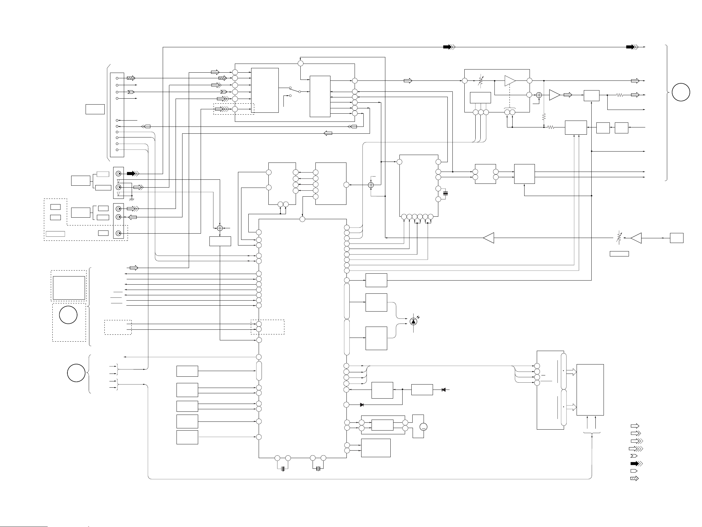
– MAIN SECTION –
CN101
SYSTEM
CONTROL
TO
HTC-W777
J6301
AV INPUT
(VIDEO 2)
AEP, UK, EE, CIS
J101
MD
VIDEO 1
EXCEPT AEP, UK,
FM/AM TUNER
TUNER UNIT IS
SUPPLIED AS
THE ASSEMBLED
EE, CIS
BLOCK
J101
MD/
VIDEO 1
A
TUNER
SECTION
(Page 14, 16)
AEP, UK, EE, CIS
B
POWER
SECTION
(Page 19)
16
1
2
7
9
5
6
14
16
17
13
VIDEO
AUDIO L
IN L
OUT LREC
IN L
COM DIN
COM DATA
ST CE
COM CLK
MUTE
STEREO
TUNED
AEP,UK
RDS DATA
RDS INT
POWER ON/OFF
AC1
AC2
VF1
VF2
ST L
IIC DATA
IIC CLK
AC1
AC2
R-CH(CD R)
R-CH(PB R)
R-CH(REC R)
KEY
MATRIX
MULTI JOG
STATION
S653
VOLUME
S652
SLIDING
SENSOR
IC504,Q513
REMOTE
SENSOR
IC503
AEP, UK, EE, CIS
R-CH
AV SWITCH
Q6301
69
68
67
66
65
64
TU
CD
V2
TC
MD/V1
VIDEO1
SELECT
SWITCH
15
4
22
SPEANA CONT
SPEANA0
26
27
SPEANA1
I2C DATA
55
56
I2C CLK
92
DATA OUT
90
DATA IN
89
LAT
93
CLK
ST MUTE
86
STREO
87
88
TUNED
17
RDS DATA
16
RDS CLK
41
AV IN
POWER ON/OFF
94
28
KEY0
I
I
31
KEY3
JOG A
20
21
JOG B
VOL A
18
VOL B
19
SENSOR IN
42
SIRCSN
43
X501
5MHz
EQ
IC111(1/2)
R-CH
SPEANA
SELECTOR
IC505
Y
Z
9
AEP,UK
X2 X1
10 11
2
Y1
1
Y2
2
Z1
3
Z2
5
10
25
MASTER CONTROL
IC501
VA CS
XT2 XT1
EQ
AMP
f1
17
16
f2
15 f3
14 f4
13 f
13 14
SPEANA
BPF FILTER
IC506
LINE
GEQ DATA
GEQ CLK
GEQ LAT
LAT2
LAT1
LEVEL B
LEVEL A
DBFB B2
DBFB B1
TA MUTE
FL DATA
FL CLK
FL LAT
FL RESET
RESET
ACCUT
MOTOR 1
MOTOR 2
X502
32kHz
42 41
4
59
60
57
58
DOLBY PRO-LOGIC
IC300
L IN
LED
LED
IN
61
R-CH
4
ENABLE2
49 50 54 51 5352
1
96
2
97
3
95
99
98
3
2
5
6
7
50
I
54
.
57
I
62
63
I
67
.
70
.
72
.
73
DATA
35
CLK
36
LAT
37
RST
38
15
32
82
83
84
85
D504
5
6
MUTE
SWITCH
Q121
LED
ON/OFF
SWITCH
Q502-512
LED
ON/OFF
SWITCH
Q531-535,
Q538-540
RESET
SWITCH
Q501
IC891
MOTOR
DRIVER
PANEL
OPEN/CLOSE
S892
2
10
CLK DATA
ENABLE
PANEL
LED
S OP OUT
C OP OUT
RESET
IC502
M
L OUT
OSC2
OSC1
M891
PANEL
MOTOR
STR-W777
VIDEO
VOLUME
IC111(2/2)
3
L-CH
S/W
MUTE
L+R
TA MUTE
S OUT
C OUT
C
POWER
SECTION
(Page 19)
J6001
MIX
MIC
36
57
39
MUTE
Q361,371
DATA
CLK
LAT
RST
40
R-CH
DISPLAY CONTROL
16
DATA
CLK
15
CS
14
RESET
13
AMP
IC113(2/2)
IC601
G15
S35
G0
S0
SELECTOR
12
I
1
64
I
61
59
I
33
31
I
23
MICON
INTERFACE
33
32 34
123
AMP
24
33
31
47
X301
8MHz
46
D507
+5.6V
IC361
5
3
MIC AMP
IC6001(2/2)
76
38
7
1
DBFB
IC112
FLUORESCENT
INDICATOR
MUTE
Q183
FL601
TUBE
SW
Q132
DET
D131
MIC AMP
IC6001(1/2)
1
RV6001(1/2)
MIC LEVEL
• R CH: Same as L ch
• SIGNAL PATH
: FM
: AUDIO(AV INPUT)
: MD/VIDEO
: VIDEO
: PB
: VIDEO(AV INPUT)
: REC
: CD
— 17 — — 18 —
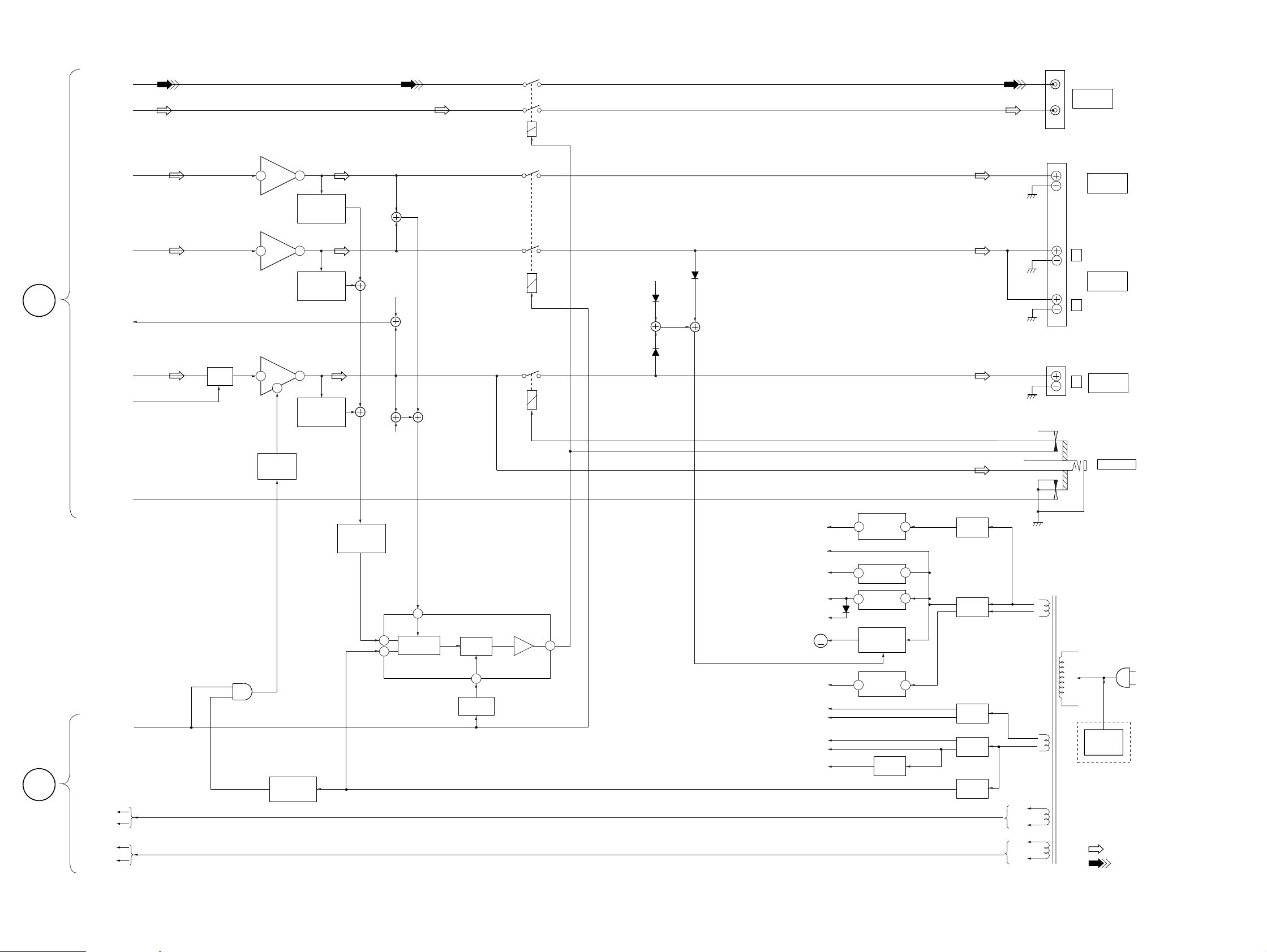
STR-W777
– POWER SECTION –
VIDEO
S/W
S OUT
POWER AMP
IC4001(1/2)
18
POWER AMP
IC4001(2/2)
13
OVER LOAD
Q4052
DET
RY781
RY741
J781
MONITOR
OUT
CENTER
SPEAKER
TB201
C
MAIN
SECTION
(Page 17)
C OUT
L+R
L-CH
TA MUTE
MUTE
MUTE
Q181
1
POWER AMP
IC901
20
8
MUTE
SWITCH
Q901
10
OVER LOAD
Q4002
15
OVER LOAD
Q952
DET
DET
OVER LOAD
SWITCH
Q851
1
4
R-CH
R-CH
2
PROTECTOR
PROTECTOR
IC851
VCC ON
MUTE
RY751
L
R-CH
D761
D751
6
D746
M901
FAN
MOTOR
ST+10V
UNREG
+12V
+7V
+5.6V
+5V
REAR
SPEAKER
R
TB751
FRONT
L
SPEAKER
R-CH
ST+10V
3 1
REG
IC804
+7V REG
IC801
IC803
REG
1
1
3
+5.6V REG
3
D813
M
FAN MOTOR
Q731,732
RECT
D810,811
T901
POWER
TRANSFORMER
+
RECT
D805-808
–
J755
PHONES
B
MAIN
SECTION
(Page 17)
16
POWER ON/OFF
AC1
AC2
VF1
VF2
D852,853
POWER ON
MUTE
Q852
7
SWITCH
Q853
-7V
SURR +B
SURR -B
+B
-B
VG
-7V REG
3
IC802
VG REG
2
Q801
— 19 — — 20 —
+
–
+
–
RECT
D809
RECT
D801
RECT
D802, 803
AC1
AC2
VF1
VF2
AC
IN
VOLTAGE
SELECTOR
S871
EA,SP,MY
• R CH : Same as L ch
• SIGNAL PATH
: FM
:VIDEO (AV INPUT)
• Abbreviation
: Saudi Arabia model.
EA
: Singapore model.
SP
: Malaysia model.
MY
THIS NOTE IS COMMON FOR PRINTED WIR-
Q
C
These are omitted
EB
ING BOARDS AND SCHEMATIC DIAGRAMS.
(In addition to this, the necessary note is printed
in each block.)
For schematic diagrams.
Note:
• All capacitors are in µF unless otherwise noted. pF: µµF
50 WV or less are not indicated except for electrolytics
and tantalums.
• All resistors are in Ω and
specified.
¢
•
: internal component.
• 2 : nonflammable resistor.
• 1 : fusible resistor.
• C : panel designation.
Note:The components identified by mark ! or dotted line
with mark ! are critical for safety.
Replace only with part number specified.
• U : B+ Line.
• V : B– Line.
• H : adjustment for repair.
• Voltages and waveforms are dc with respect to ground
under no-signal (detuned) conditions.
• Voltages are taken with a VOM (Input impedance 10 MΩ).
Voltage variations may be noted due to normal production tolerances.
• Waveforms are taken with a oscilloscope.
Voltage variations may be noted due to normal production tolerances.
• Circled numbers refer to waveforms.
• Signal path.
F : FM
f : AM
L : AUDIO (AV INPUT)
g : MD/VIDEO
i : VIDEO (AV INPUT)
E : PB (DECK A)
G : REC (DECK B)
J : CD
• Abbreviation
EE : East European model.
EA : Saudi Arabia model.
SP : Singapore model.
MY : Malaysia model.
AUS : Australian model.
TH : Thai model.
1
4
/
W or less unless otherwise
For printed wiring boards.
Note:
• X : parts extracted from the component side.
• Y : parts extracted from the conductor side.
•
p : parts mounted on the conductor side.
®
•
•
: Through hole.
¢
: internal component.
• b : Pattern from the side which enables seeing.
• Indication of transistor
C
EB
These are omitted
— 21 —
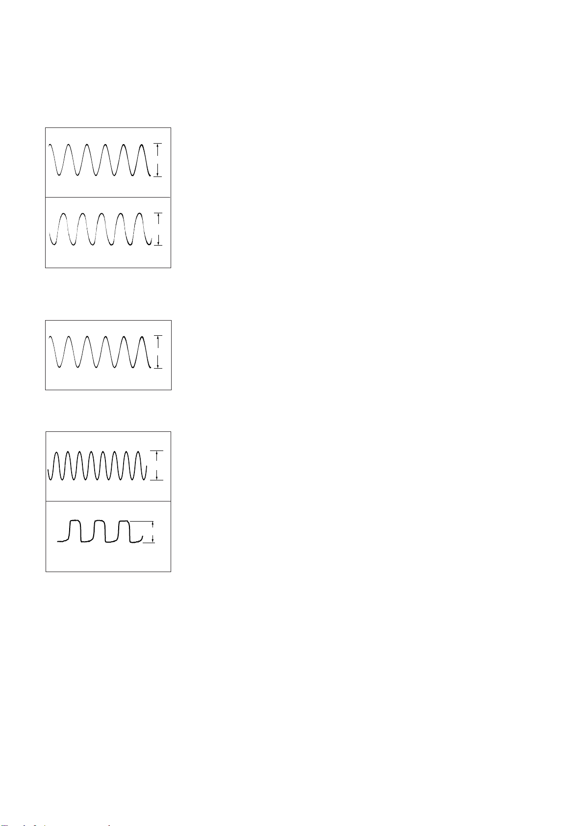
Waveforms
32.768kHz
5Vp-p
– TUNER SECTION –
(AEP , UK model)
1
4.2Vp-p
4.5MHz
IC21 @¢ XOUT
2
2Vp-p
4.332MHz
IC1752 !¢ OEC O
– Tuner Section –
(East European, CIS model)
1
4.2Vp-p
4.5MHz
IC21 @¢ XOUT
– DISPLAY Section –
1
5MHz
IC501 0 X2
2
IC501 !£ XT2
5.5Vp-p
– 22 –
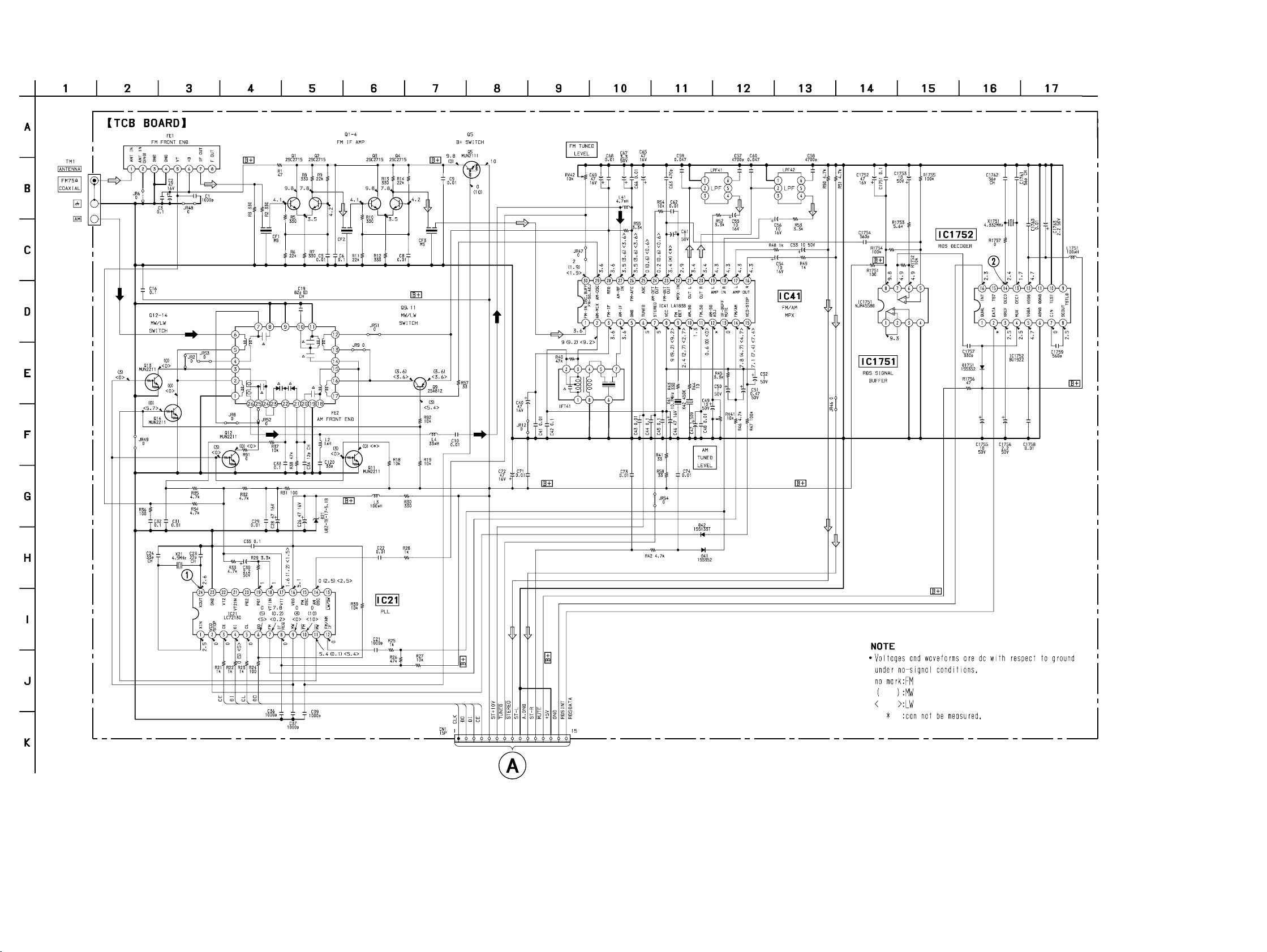
STR-W777
5-3. SCHEMATIC DIAGRAM – TUNER SECTION – (AEP, UK model) • Refer to page 22 for Waveforms.
• Refer to page 56 for IC Block Diagrams.
16
(Page 32)
— 23 — — 24 —
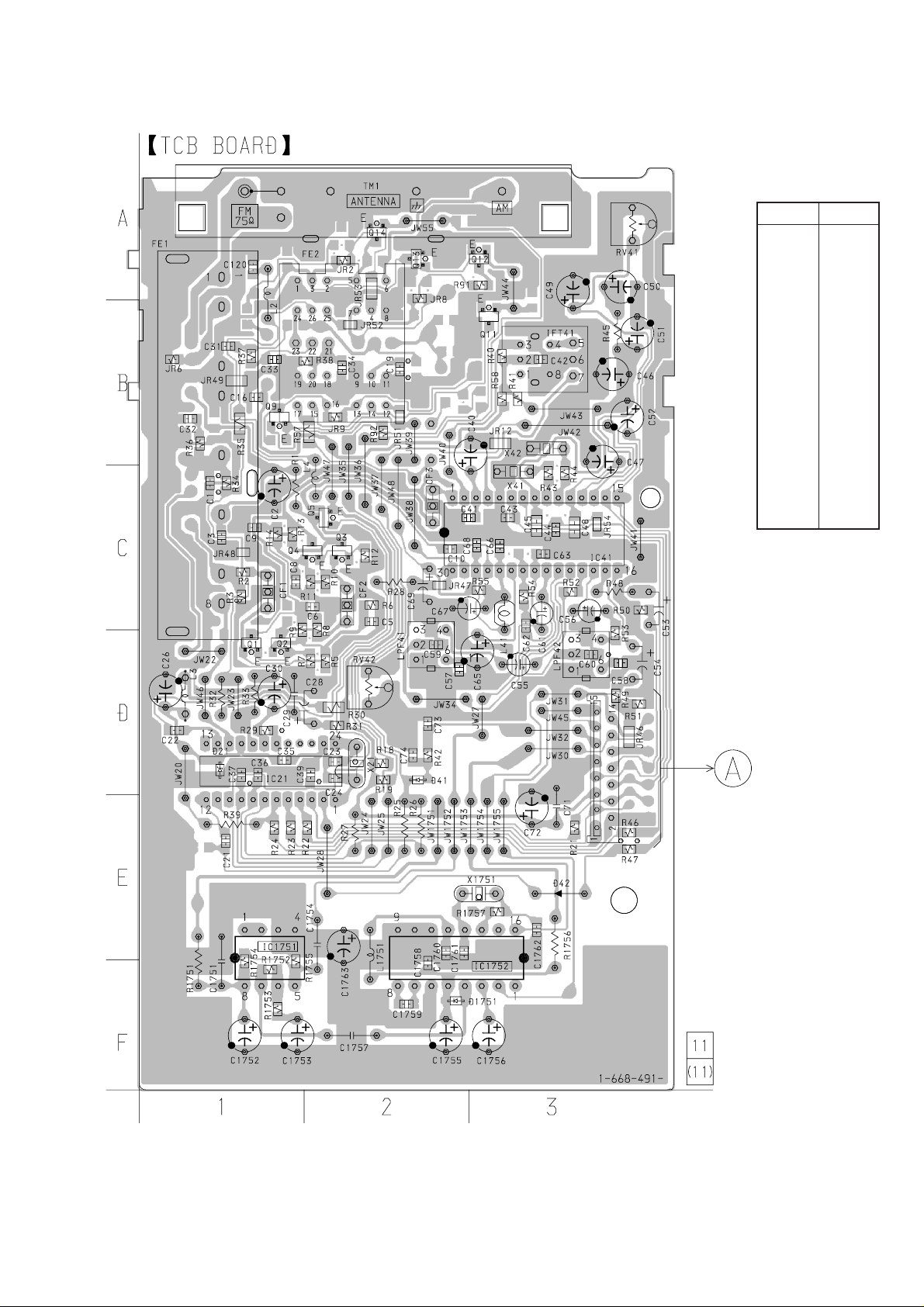
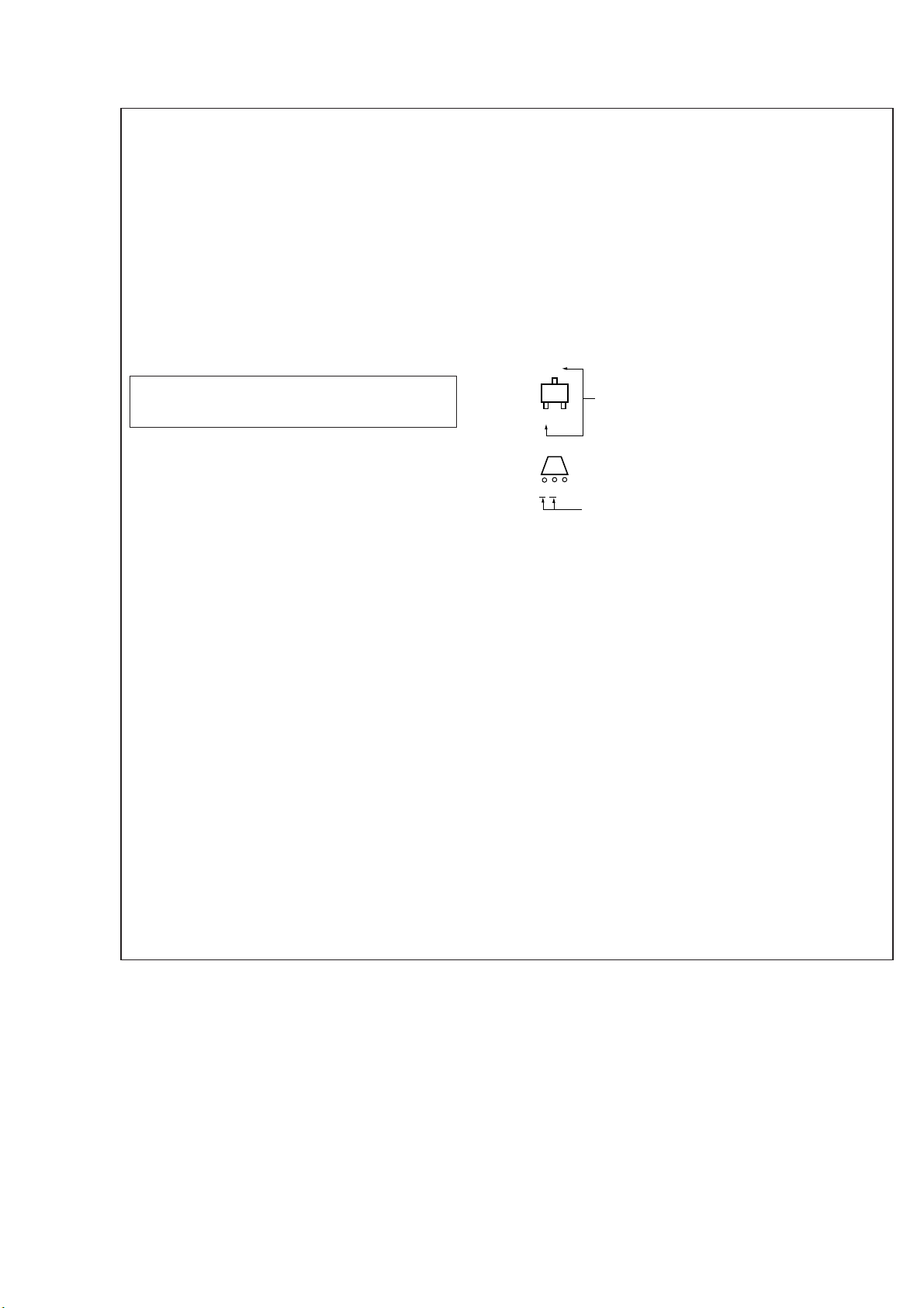
5-4. Printed Wiring Board – Tuner Section – (AEP, UK model)
• Refer to page 12 for Circuit Boards Location.
STR-W777
• Semiconductor
Location
Ref. No. Location
D21 D-1
D41 D-2
D42 E-3
D1751 F-2
IC21 D-1
IC41 C-3
IC1751 E-1
IC1752 F-3
Q1 D-1
Q2 D-1
Q3 C-2
Q4 C-2
Q5 C-2
Q9 B-1
Q11 B-3
Q12 A-3
Q13 A-2
Q14 A-2
(Page 30)
16
— 25 —
 Loading...