

Page 1

3-755-038-21(2)
FMStem/FM-AM
Receiver
Operating Instructions
STR-GX49ES
1992 by Sony Corporation
Page 2
WARNING
To prevent fire or shock hazard, do not
expose the unit to rain or moisture.
CAUTION
RISK OF ELECTRIC SHOCK
DO NOT OPEN
CAUTION: TO REDUCE THE RISK OF ELECTRIC SHOCK,
■ DO NOT REMOVE COVER (OR BACK).
NO USER-SERVICEABLE PARTS INSIDE.
REFER SERVICING TO QUALIFIED SERVICE PERSONNEL.
This symbol is intended to alert the user to
the presence of uninsulated "dangerous
voltage" within the product's enclosure that
may be of sufficient magnitude to constitute
a risk of electric shock to persons.
This symbol in intended to alert the user to
the presence of important operating and
maintenance (servicing) instructions in the
literature accompanying the appliance.
INFORMATION
This equipment generates and uses radio frequency
energy and if not installed and used properly, that is, in
strict accordance with the manufacturer's instructions, may
cause interference to radio and television reception. It has
been type tested and found to comply with the limits for a
Class B computing device in accordance with the
specifications in Subpart J of Part 15 of FCC Rules, which
are designed to provide reasonable protection against
such interference in a residential installation. However,
there is no guarantee that interference will not occur in a
particular installation. If this equipment does cause
interference to radio or teievision reception, which can be
determined by turning the equipment off and on, the user is
encouraged to try to correct the interference by one or
more of the following measures:
Reorient the receiving antenna
Relocate the equipment with respect to the receiver
Move the equipment away from the receiver
Plug the equipment into a different outlet so that
equipment and receiver are on different branch circuits,
if necessary, the user should consult the dealer or an
experienced radio/television technician for additional
suggestions. The user may find the following booklet
prepared by the Federal Communications Commission
helpful:
“How to identify and Resolve Radio-TV Interference
Problems". This booklet is available from the U.S.
Government Printing Office, Washington, DC 20402, Stock
No. 004-000-00345-4.
Note to CATV system installer
This reminder is provided to oall the CATV system
installer's attention to Article 820-40 of the NEC that
provides guidelines for proper grounding and, in
particular, specifies that the cable ground shall be
connected to the grounding system of the building, as
close to the point of cable entry as practical.
Owner's Record
The model number is located on the rear exterior and serial
number is on the rear. Record the serial number in the
space provided below. Refer to these numbers whenever
you call upon your Sony dealer regarding this product.
Model No. STR-GX49ES Serial No.
For the customers in Canada
CAUTION :
--------------------------------
TO PREVENT ELECTRIC SHOCK, DO NOT USE THIS
POLARIZED AC PLUG WITH AN EXTENSION CORD,
RECEPTACLE OR OTHER OUTLET UNLESS THE
BLADES CAN BE FULLY INSERTED TO PREVENT
BLADE EXPOSURE.
This apparatus complies with the Class B limits for radio
noise emissions set out in Radio Interference Regulations.
Page 3

Introduction
Features
Precautions
Chapter 1 Getting Started
Installing
............................................
.......................................
............................................
Notes on installing
Installing batteries
.......................
.......
................
Changing the AM tuning interval.
Connecting the system
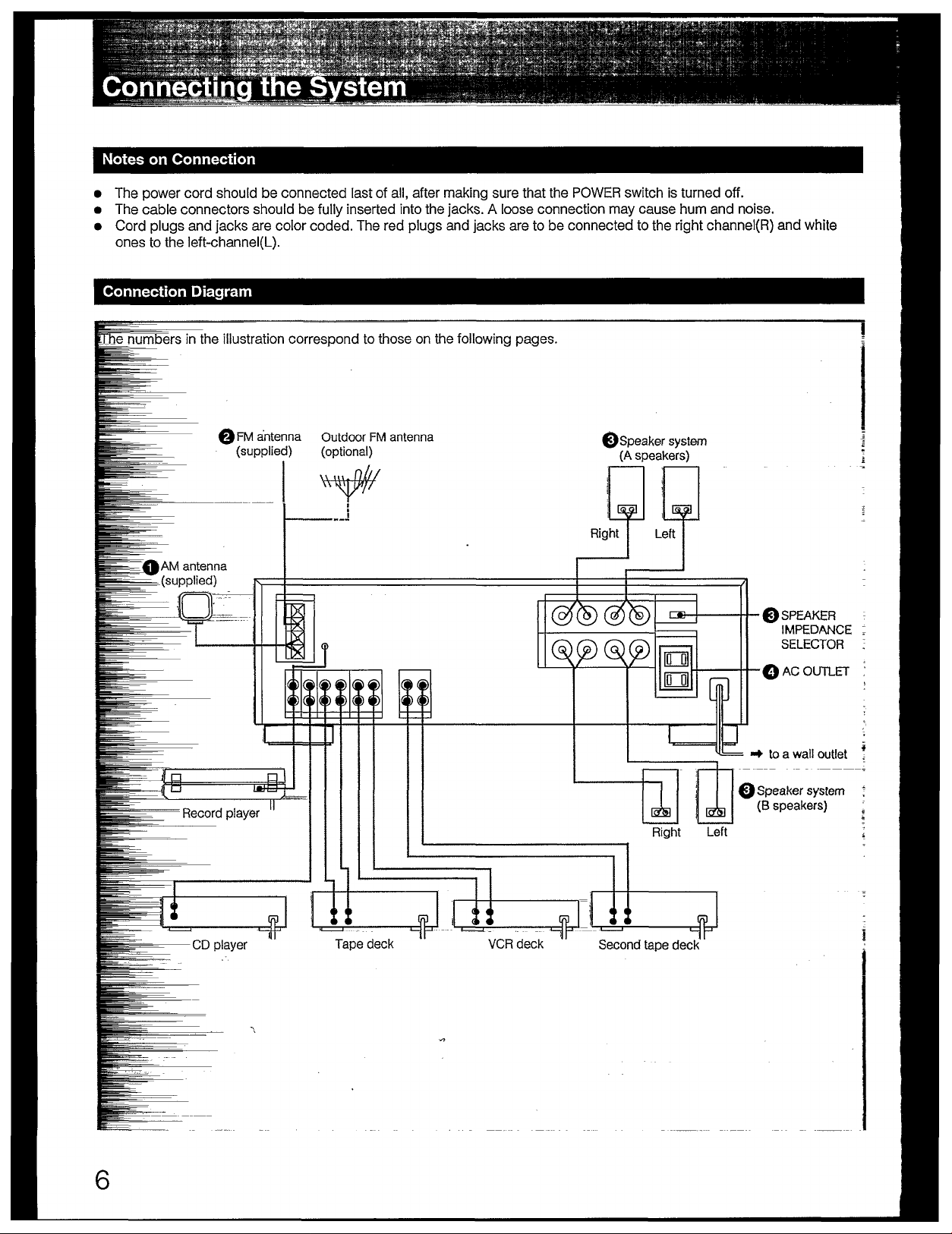
Notes on connection
......................
....................
Connection diagram....,................
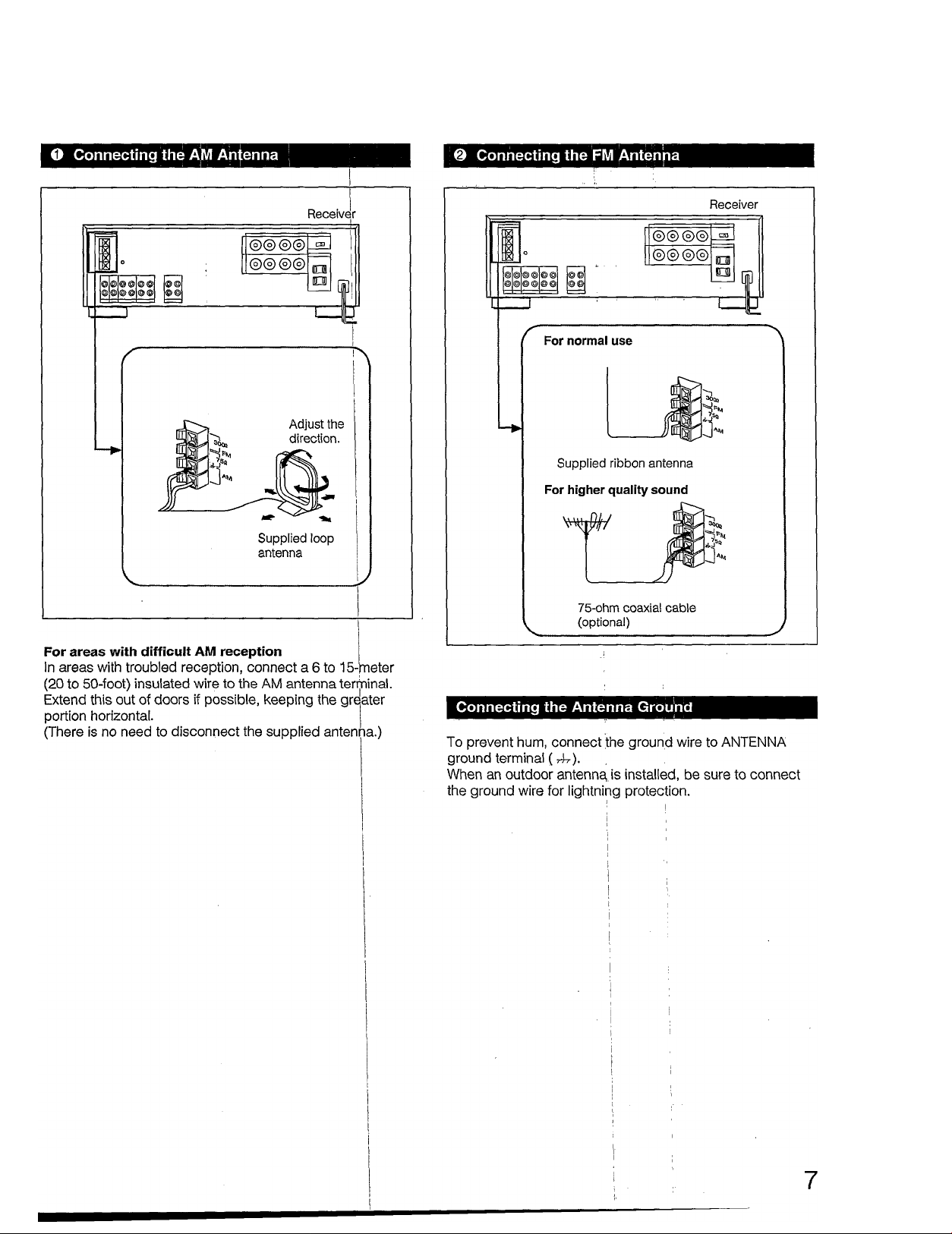
Connecting the AM antenna
Connecting the FM antenna
........
........
Connecting the antenna ground .
Connecting speaker systems.......
Using AC outlets
Parts Identification
...........
..............
.............................
Front panel...................................
Remote commander RM-S103....
Chapter 2 Using Your Receiver
Audio adjustment
Volume adjustment
Balance adjustment
...............-.........
..................
................
Sound quality adjustment.
Receiving FM/AM broadcasts..................................J
Tuning in an FM station automatically
— Automatic Tuning
..................................................
Tuning in an FM/AM station manually
— Manual Tuning
Memorizing a station
Tuning in a preset station
.....................................................
...................................................
............................................
Listening to program source other than broadcasts
Recording on an audio tape
Recording
....................................................................
..............................................
Tape dubbing.............................................................. 16
Recording on a VCR
Recording audio programs
........................................................
........................................
............
...........
.4
.4
...5
...5
,..5
...5
...6
...6
...6
...7
...7
.. 7
...8
...8
...9
...9
.10
.11
.11
.11
.11
12
12
13
13
14
15
16
16
17
17
Chapter 3 Other Information
Troubleshooting
Specifications
Quick reference
.......................
..........................
.......................
.
.Back
.18
.20
cover
Page 4

Precautions
The STR-GX49ES is a receiver which controis audio/video
sources. The unit aiiows you to switch easiiy among a
variety of audio/video programs.
Amplifier
• Optical Legato Linear A System allows the receiver to
operate automatically as a class A amplifier when the
level is low and as a class B amplifier when the level is
high without disturbing the sound signal. This minimizes
total harmonic distortion at every sound stage.
• These receivers have a spontaneous twin drive power
circuit. Condensers having large capacity are used
independently for the voltage amplification drive stage
of class A and power output stage of class B. Thus, a
stable output and high quality sound are obtained,
resulting in exclusion of power interferences.
The class A stage realizes a stable operation free from
interference of the power stage even when an
instantaneous or strong output is received.
• A source direct switch is employed to reproduce high
fidelity sound.
Any source can be reproduced without passing through
the circuits of tone control, loudness switch and balance
control.
Tuner
• Precise tuning is obtained thanks to the quartz-locked
digital synthesizer system.
• A total of 30 FM/AM stations can be preset in 3 memory
pages (A, B and C) that allow you to classify stations.
On safety
• Operate the unit only on 120 V AC, 60 Hz.
• Should any solid object or liquid fall into the cabinet,
unplug the unit and have it checked by qualified
personnel before operating it any further.
• Unplug the unit from the wall outlet if it is not to be used
for an extended period of time. To disconnect the cord,
pull it out by grasping the plug. Never pull the cord
itself.
• One blade of the plug is wider than the other for the
purpose of safety and will fit into the power outlet only
one way. if you are unable to Insert the plug fully Into the
outlet, contact your dealer.
On operation
• Before making program source connections, be sure to
turn the power switch off and unplug the unit.
• When the unit is not used, turn the power off. to
conserve energy and to extend the useful life of your
unit.
On cleaning the cabinet
Clean the cabinet, panel and controls with a soft cloth
lightly moistened with mild detergent solution. Do not use
any type of abrasive pad, scouring powder, or solvent such
as alcohol or benzine.
For the customers in the U.S.A.
For detailed safety precautions, see the “IMPORTANT
SAFEGUARDS’’ leaflet.
Remote commander
• The remote commander allows you to control most of
Sony’s audio equipment from a distance.
If you have any question or problem concerning your unit,
please consult your nearest Sony dealer.
Page 5
■■
Ml)- f
Notes on Installatior^
To prevent internal heat buildup in the unit, j
place the unit in a location with adequate air circulation.
Do not install the unit: |
— near heat sources such as radiators or air ducts.
— in a place subject to direct sunlight, excessive dust,
mechanical vibration or shock.
Do not place anything on top of the cabinet.
The top ventilation holes must be unobstructed for the
proper operation of the unit and to prolong the life of its
components.
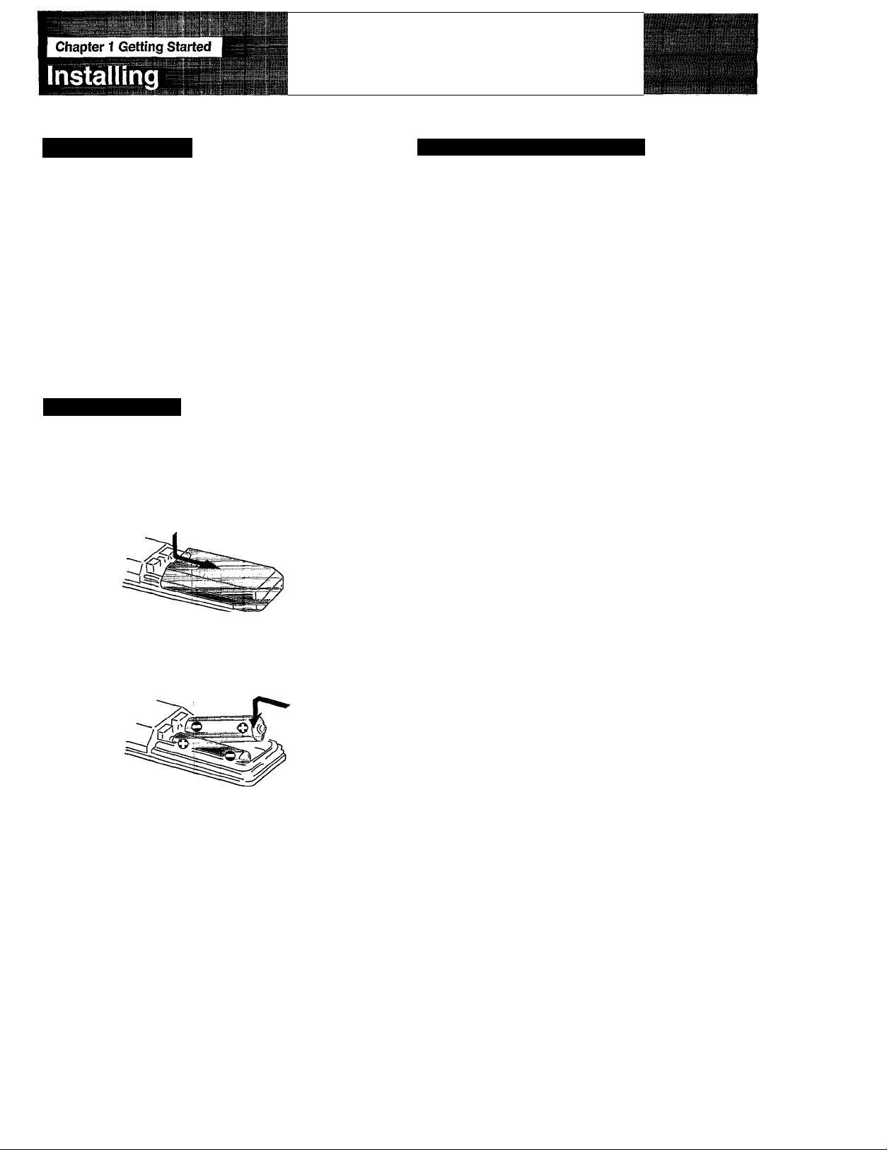
Installing Batteries
Before operating remote commander, install the batteries
as shown.
1
1 Open the cover.
Changing the AM tuning interval
The AM tuning interval is preset to 10 kHz. To use the
receiver where the frequency allocation system is based on
a 9 kHz interval, make the following adjustments.
I
1 Turn on the power and tune in any AM station.
2 Turn off the power.
3 Press POWER while pressing the “+" TUNING
button.
To reset the AM tuning interval, repeat the above steps.
Caution
When the interval is changed, all preset stations which you
have memorized will be erased. After changing the interval,
be sure to preset the stations again.
2 Insert two size AA (R6) batteries with correct
polarity.
Do not throw away the carton and packing material!
It will be an ideal container when transporting the system for
repair work, etc.
To avoid damage caused by battery leakage and corrosion
When the commander will not be used for a long time,
remove the batteries.
Normal operation can be expected about a half yejar using
Sony SUM-3 (NS), and a year using Sony AM-3 (NyV)
alkaline batteries. |
When the batteries are run down, the remote commander
will not operate the unit. In this case, replace batte'i-ies with
new ones.
Page 6
Page 7
Page 8

Connecting the System
Connecting Speaker Systems
r
1
Tn A“
0000
Speaker (R)
Note
Once the speakers have been connected, move
SPEAKERS selector (on the front panel) to A, B or A + B
setting.
When using the headphones, set the SPEAKERS
selector to OFF.
0000
^ t -t -i
I
to the second
speaker system
0©0
©
©0©©
Speaker (L)
e|0 0]e
Receiver
* \
15 mm
2
Set the SPEAKER IMPEDANCE SELECTOR according to the
impedance of the used speakers, using a screwdriver.
CAUTION
When you operate two speaker systems simultaneously, be
sure to use the speakers with the impedance of more
than 8 ohms and set the SPEAKER IMPEDANCE SELECTOR to
4-60.
Speaker impedance and power capability
This receiver is designed to work best with speakers having
nominal impedance from 4 to 16 ohms at rated 50 watts RMS per
channel with an 8 ohms load from 20 — 20,0(X) Hz.
3
m
)
8
Page 9

..»—:.i•■™W■'■•■■'*-•■"" .i'<"i"ti""".i' '"■■!
............
} „■
’ ¡.•■v-!T- ■= r-“ ■ -■■ ■■■-■■! »
Q] POWER switch
\2\ SHIFT button (Pages 13 and 14)
¡3] Remote control sensor
E] TAPE MONITOR indicator
[H Display window
[6] TAPE MONITOR switch (Page 15)
IZl Function selectors
[8] MUTING button and indicator (Page 11)
m ATTENUATOR and indicator (Page 11)
in SPEAKERS selector (Page 8)
El HEADPHONES jack
in FM MODE button (Page 12)
OH FM TUNE MODE switch (Pages 12 and 13)
[14] FM/AM BAND selectors (Pages 12 and 13)
HI MEMORY button (Page 13)
n TUNING -/+ buttons (Pages 12.and 13)
i
OH PRESET TUNING -/+ buttons (Page 14)
OH Numeric buttons (Pages 13 and 14)
t
I
n TONE controls (Page il)
n SOURCE DIRECT buttpn (Page 11)
I ■ -
lU LOUDNESS switch (Page 11)
!• !■
mi BALANCE control (Page 11)
9
Page 10

Parts Identification
Remote Commander RM-S103
Q] POWER button
ID DBFB button
This button does not operate with this receiver.
m TUNER PRESET +/- and SHIFT buttons
(Pages 13 and 14)
E! VOLUME +/- buttons
(S SURROUND button
This button does not operate with this receiver.
¡§1 MUTiNG button (Page 11)
[7] CD piayer operation buttons*
D. (disc) SKIP: When your CD player is equipped with a
multi-disc changer, use this button to select loaded
disc.
CD ►: Selects the CD function and starts CD playback.
d] DECK B operation buttons* (also for single tape
deck)
DECK B ◄/►: Select tape function and start tape
playback on deck B.
[9] DECK A operation buttons*
DECK A ◄/►: Seiect tape function and start tape
playback on deck A.
Qfil Function select buttons
10
These buttons control Sony audio components.
Page 11

ri f j f fiv;!»} > ¡i If »0*1 ^jifif^l
Volume Adjustment
Press again to restore the same listening level as before.
Sound Quality Adjustment
To adjust the tone quality
Adjust BASS or TREBLE for the optimum sound.
To reinforce the bass frequency response
Press LOUDNESS.
The lower the speaker output level is, the more bass
frequency sound is emphasized.
To change the relative strength of the right and left
speaker output
Adjust BALANCE to correct stereo imaging, when the
speaker position is not symmetrical. i
To bypass the tone control circuit
Press SOURCE DIRECT.
BASS and TREBLE tone controls, BALANCE control and
LOUDNESS are bypassed.
11
Page 12

Receiving
VlSir^M
.
^ ._____________ . ‘ '.Ì‘. ’ ■ „^aifii.■SÉltt
É^m
roadcasts
Tuning in an FM Station Automatically
— Automatic Tuning
Il * I «
When sweeping does not stop at the desired station
The signal strength is weak.
To stop sweeping, press FM TUNE MODE again. AUTO
indicator disappears and automatic tuning stops.
Then tune in the station as described in “Manuai Tuning".
When an FM stereo program is noisy or hard to receive
Press FM MODE. The MONO indicator appears (the sound
is heard in monaural, but the reception will be improved).
To return to the stereo mode, press the button again or tune
in another station.
I ""I
AUTO indicator appears.
For higher
frequency
Page 13

'uning in an FM/AM Station Manually
- Manual Tuning
Memorizing a Station
r
A total of 30 FM/AM stations oan be memorized in any
desired sequence.
POWER ON
HD
r(-®
o
Select
SPEAKERS
2 4
3 1
1 Tune in the desired station.
-TUNING +
For lower
frequency
Select the memory page (A, B, and C).
(D 0 o o (D
\— I
__=___________
\
For higher
frequency
SHIFT
3 Press MEMORY so that the MEMORY indicator
lights up.
MEMORY
4 While the MEMORY indicator is on, press the
desired number.
1 2
13
Page 14

Receiving FM/AM Broadcasts
Tuning in a Preset Station
Method B: Scan tuning
SPEAKERS
Press TUNER.
1
TUNER
2 Press PRESET TUNING - or +.
-PRESET TUNING +
Replacing a preset station
Preset another station on the number of the station to be
replaced. The previously preset station will be erased.
IMPORTANT
The memorized station is maintained for approximately one
month even if the power cord is disconnected from the AC
power source. If they are erased, store the stations again.
For lower
preset number
A1 —T AO
+
t +
--------------►
Adjust the volume.
M
-----
CO
ATTENUATOR
+
+
-► C1
For higher
preset number
B1
+
+
BO
14
Page 15

Listening to Program Source other than Broadcasts
POWER-*-ON
m
rl-®
o
® CD o o (j)
Record player |
Select
SPEAKERS
CD player |
Tape deck I
VCR 1
1
Select the program source.
RJNCrrON
■ R|^iword
C^pactdlsc
ij^prpgrams
PHONO
CD
VIDEO
Taped programs TAPE or TAPE MONITOR
1 CD
TUNER
PHONO
Note on TAPE MONITOR button
The TAPE MONITOR button has priority over other function
selectors. Be sure to release the TAPE MONITOR button except
when listening to taped program. Otherwise, the program source
selected with the function selector cannot be heard.
tWe
ON/OFF
start the program.
VIDEO
b
TAPE
Page 16

Recording on an Audio Tape
Recording
POWER ON
db
(D
o
Record player ~1
(D dD ® ® dD
■ to TAPE
5 I CD player | I Tape deck | 4
VCR
c
]
1 Turn on the receiver and the equipment to be
used.
Tape Dubbing
REC OUT
3,6
1 Turn on the receiver and the equipment to be
used.
Seiect the desired program source.
For an FM/AM broadcast, tune in the desired
station.
Set the tape deck in the recording mode.
Start the desired program source.
To monitor recorded sound whiie recording
If a tape recorder with three-head system is connected to
TAPE MONITOR jacks, recorded sound can be monitored.
Select recording tape recorder using the TAPE MONITOR
button. The recorded sound is immediately fed back to the
amplifier and output to the speakers.
Note on recording
The setting of the volume, BASS, TREBLE, and BALANCE controls
do not have any effect on recording.
2 Insert the recorded tape into deck connected to
the TAPE jacks.
3 Insert a blank tape into the tape deck connected
to the TAPE MONITOR Jacks and adjust the
recording level.
Press TAPE.
5 Start the playback of the tape deck for
playback.
G Set the tape deck for recording in the recording
mode.
16
Page 17

Recording on a VCR
Recording Audio Programs
To record an audio program source on a video tape,
proceed as follows:
1 Tig>e deck I
1 Turn on the receiver and the equipment to be
used.
Seiect the desired program source.
3 insert a video tape into the VCR and adjust the
recording ievei.
Start the program source and set the VCR in the
recording mode.
Page 18

I Chapter 3 Other Information
Troubleshooting
Before proceeding through the check list below, examine the connections and the
procedures outlined the manual.
Should any problem persist after you have checked the foilowing items, consuit your
nearest Sony dealer.
Problem
Sound is not heard.
m.
fe
I
w-
mm,
i
One channei does not transmit
audio, or the volume from the left
and right speakers is
unbalanced.
There is an abrupt loss of sound
from one or both of the speakers,
and the PROTECTOR indicator
flickers in the display window.
Cause Remedy
The TAPE MONITOR jacks are not in
use and the TAPE MONITOR button
is pressed to ON.
The speaker or program source
equipment is not connected
correctly.
The correct speakers are not
selected with SPEAKERS selector.
The correct FUNCTION selector is not
pressed.
The volume is set to minimum.
The BALANCE control is not set
appropriately.
The speaker or program source is not
connected correctly.
A short-circuit problem activates the
protective circuit.
Press the TAPE MONITOR button to
set to OFF.
Connect the equipment correctly.
(See pages 6 to 8.)
Set the SPEAKERS selector correctly.
Press the correct FUNCTION
selector.
Increase the volume.
Adjust the BALANCE control.
Connect the equipment correctly.
(See pages 6 to 8.)
Turn off the receiver, eliminate the
short-circuit problem and turn on the
power again. If there is no
short-circuit, consult your nearest
Sony dealer.
Sound transmitted from the
speakers is reversed.
Severe hum or noise is heard.
i
I
fe'*
Wr
The SPEAKER IMPEDANCE
SELECTOR on the rear is not set
correctly.
The speakers are not connected
correctly.
The connecting cords are not of
shielded type.
A transformer, motor, TV or
fluorescent light affects the
connecting cord.
The audio components are too close
to a TV set.
The receiver is not grounded.
The connections are loose. Make secure connections.
The plugs and jacks are dirty. Wipe the plugs and jacks with a cloth
Set the SPEAKER IMPEDANCE
SELECTOR correctly.
Connect the speaker with the correct
0 0 polarities. (See page 8.)
Use shielded type cords.
Place the connecting cords in a
location away from a transformer or
motor, and at least 3 meters (10 feet)
from a TV set or a fluorescent light.
If both are used at the same time,
separate the TV from the audio
components.
Connect the ground wire to the
antenna ground terminal.
18
Page 19

STEREO indicator flickers or
does not appear when receiving
stereo programs.
A very weak FM station or a noisy
FM program is received.
Adjust the antenna or connect an
external FM antenna.
Press the FM MODE button to
disengage the stereo mode.
The desired station cannot be
found during Automatic Tuning.
Preset stations cannot be tuned
in.
AM station cannot be tuned in.
I The remote commander does
; not operate.
The |signal strength is too weak for
Automatic Tuning.
The stations have not been
merhorized.
The AM tuning interval is set
incofrectiy.
The batteries are exhausted.
There is any object between the unit
and the commander head.
Adjust the antenna.
Tune in the station with the Manual
Tuning system. (See page 13.)
Memorize the stations. (See page
13.)
Qhange the tuning interval
according to the AM frequency
allocation system of your country.
(See page 5.)
Replace the batteries with new
ohes.
Remove the object.
19
Page 20

Specifications
Audio Power Specifications
POWER OUTPUT AND TOTAL HARMONIC DISTORTION
With 8-ohm load, both channels driven,
from 20 - 20,000 Hz, rated 60 watts per
channel minimum RMS power, with no
more than 0.08% total harmonic distortion
from 250 milliwatts to rated output.
With 4-ohm load, both channels driven,
from 20 - 20,000 Hz, rated 60 watts per
channel minimum RMS power, with no
more than 0.08% total harmonic distortion
from 250 milliwatts to rated output.
other Specifications
Amplifier section
Dynamic power output
75 watts + 75 watts (8 ohms, at 1 kHz IHF)
100 watts + 100 watts (4 ohms, at 1 kHz IHF)
105 watts + 105 watts (2 ohms, at 1 kHz IHF)
Harmonic distortion
Less than 0.08% at rated output
Frequency response
PHONO; RIAA equalization curve ±0.5 dB
CD,TAPE
VIDEO,
TAPE MONITOR
Residual noise
Damping factor
Inputs
Sensitivity Impedance
PHONO 2.5 mV
CD, VIDEO
TAPE,
TAPE
MONITOR
150 mV
5 Hz-50 kHz^; dB
Less than 70 [J.V (8 ohms, network
A)
50 (8 ohms, 1 kHz)
50 kilohms
50 kiiohms
S/N (weighting
network, input level)
87 dB
79 dB* (A, 2.5 mV)
105 dB
86 dB* (A, 150 mV)
20
78 IHF
Page 21

Tuning
..........
Antenna
Intermediate
frequency
Sensitivity at
50 dB quieting
Usable
sensitivity
Signal-to-noise
ratio
Harmonic
distortion
Selectivity
Separation
Frequency
response
IM distortion
Capture ratio
AM suppression
ratio
FM tuner section AM tuner section
87.5 —108 MHz
530 —1,7jl0kHz
(with the /s^M tuning
interval set at 10
kHz)
j
531 — 1,710 kHz
(with the AM tuning
interval set at 9
kHz) 1
300 ohms,balanced
75 ohms,
unbalanced
10.7 MHz
External at
terminal, Ic
antenna
450 kHz
tenna
op
18.3 dBf, 2.2|.iV
(mono)
38.3 dBf, 22.5 |iV
(stereo)
11.2 dBf, 2 IJ.V (IHF)
Loop anterjina; 50
dB/m (at 1 jOOO kHz)
External antenna:
100|iV (at 1,000
kHz) j
82 dB (mono)
54 dB (at 5
0 mV/m)
76 dB (stereo)
0.1% (mono), 0.2%
(stereo) at 1 kHz
60 dB at 400 kHz
0.3% (at 5C
400 Hz)
) mV/m,
:
Í
40 dB at 10 kHz
35 dB at 9 kHz
45 dB at 1 kHz
30 Hz — 15 kHz
:°:l dB
0.1% (mono)
0.2% (stereo)
I
i
I
I
i
i
1.2 dB
I
54 dB
I
I
General
System
Tuner section: PLL quartz-locked
digital synthesizer system
Preamplifier section; low-noise NF
type equalizer amp
Power amplifier section; pure
complementary SEPP
Power requirements
Power consumption
120 VAC. 60 Hz
USA model: 130 watts
Canadian model: 150 W
AC outlets
Two switched
USA model: 100 W
Canadian model: 120 W/1A
Dimensions
Approx. 430 X 135 X 375 mm
(w/h/d)
(17x5 ®/g X 14 % inches)
including projecting parts and
controls
Weight
Approx. 8.1 kg (17 lb 14 oz) net
Approx. 9.5 kg (21 lb) in
shipping carton
Accessories supplied
FM wire antenna (1)
AM loop antenna (1)
Remote Commander (1)
RM-S103
Sony batteries SUM-3(NS)
(for the remote commander) (2)
Design and specifications are subject to change without
notice.
Image response
ratio
IF response
ratio
Spurious
response ratio
RF
Intermodulation
Auto tuning
|Threshold
80 dB
90 dB
100 dB
65 dB (800 kHz)
30 dBf
i
I
I
j
I
I
I
21
Page 22

Quick Reference
Tuning in an FM/AM
station manually
Tuning in an FM
station automatically
POWER
3
-
POWER
H— R
Tuning in the
desired station.
TUNER
TUNER
SHIFT
c
FM-BAND-AM
or
FM - BAND FM TUNE MODE
AUl
MEMORY
1 2 3 4 5 6
-TUNING H
or
-TUNING H
or
Memorizing a station
Tuning in a preset
station
POWER
g —
FM //7*7.3/7mhz FI
□
NEB
SHIFT
c
« - « (memorO
FM lu H — FM I0H. 30,^R E
1 2 3 4 5 6
I T T-~i
..............................
- PRESET TUNING H
or
I : I -
Sony Corporation
Printed in Japan
 Loading...