

Sony STRDE-415 Service manual
STR-DE315/DE415
SERVICE MANUAL
Photo : STR-DE415 model
Manufactured under license from Dolby Laboratories
Licensing Corporation.
“DOLBY”, “PRO LOGIC” and the double-D symbol
are trademarks of Dolby Laboratories Licensing
Corporation.
SPECIFICATIONS
Amplifier section
Power output
Stereo mode (DIN 1kHz, 4ohms)
STR-DE415 :
80W + 80W
STR-DE315 :
80W + 80W
Surround (DIN 1kHz, 4ohms)
mode Front :
STR-DE415 : 70W/ch
STR-DE315 : 60W/ch
Center :
STR-DE415 : 70W
STR-DE315 : 60W
(only in PROLOG
MODE)
Rear :
STR-DE415 :
(DIN 1kHz, 4ohms)
70W
STR-DE315 :
(DIN 1kHz, 4ohms)
60W
Frequency PHOTO : RIAA
response equalization curve
± 0.5dB
TV/LD, CD, TAPE/MD,
VIDEO :
10Hz - 50kHz ± 1dB
Inputs
Sensitivity Impedance S/N
PHONO 2.5mV 50 74dB
(MM) Kilohms 72dB***
CD, 200mV
T APE/MD,
TV/LD, (A, 150mV)
VIDEO
Output TAPE/MD REC OUT :
Muting Full mute
150mV
Kilohms 82dB***
Voltage : 150mV,
Impedance : 10 kilohms
VIDEO AUDIO OUT :
Voltage : 150mV,
Impedance : 10 kilohms
MIX AUDIO
OUT (STR-DE415 only)
Voltage : 2V
Impedance : 10 kilohms
PHONES :Accepts low
and high impedance
headphones
(Weighting
network,
input level)
(A,2.5mV)
50 82dB
***78 IHF
AEP Model
UK Model
BASS BOOST + 10dB at 70Hz
TONE ± 8dB at 100Hz and
FM tuner section
Tuning range 87.5 - 108.0MHz (OTHER)
Aerial range 75ohms, unbalanced
Sensitivity Mono : 18.3 dBf, 2.2µV
Usable 11.2 dBf, 1µV
sencitivity /75ohms (IHF)
S/N Mono : 76dB
Harmonic Mono : 0.3%
diatortion at Stereo : 0.5%
1kHz
Separation 45dB at 1kHz
Frequency 30Hz - 15kHz
response
10kHz
65.0 - 74.0MHz
(East European)
/75ohms
Stereo : 38.3 dBf, 22.5µV
/75ohms
Stereo : 70dB
+ 0.5
dB
— Continued on next page —
– 2
MICROFILM
FM STEREO/FM-AM RECEIVER

Selecitivity 60dB at 400kHz
AM tuner section
Tuning range 522 - 1611 kHz
Aerial Loop aerial
TABLE OF CONTENTS
Specifications ··············································································· 1
1. GENERAL
Location and Function of controls················································3
Usable 50dB/m (at 999kHz)
sensitivity
S/N 54dB (at 50mV/m)
Harmonic 0.5% (50mV/m,
distortion 400Hz)
Selectivity 35dB
General
system Tuner section : PLL
quartz-locked digital
synthesizer system
Preamplifier section :
Low-noise NF type
equalizer
Power amplifier section :
Pure-complimentary
SEPP
Power 230VAC, 50/60Hz
requirements
Power STR-DE415 : 175W
consumption STR-DE315 : 175W
AC outputs Switched 100W
(except for the U.K.
model)
2. EXPLANATION OF IC TERMINALS···················5
3. DIAGRAMS
3-1. Circuit Boards Location ····················································· 6
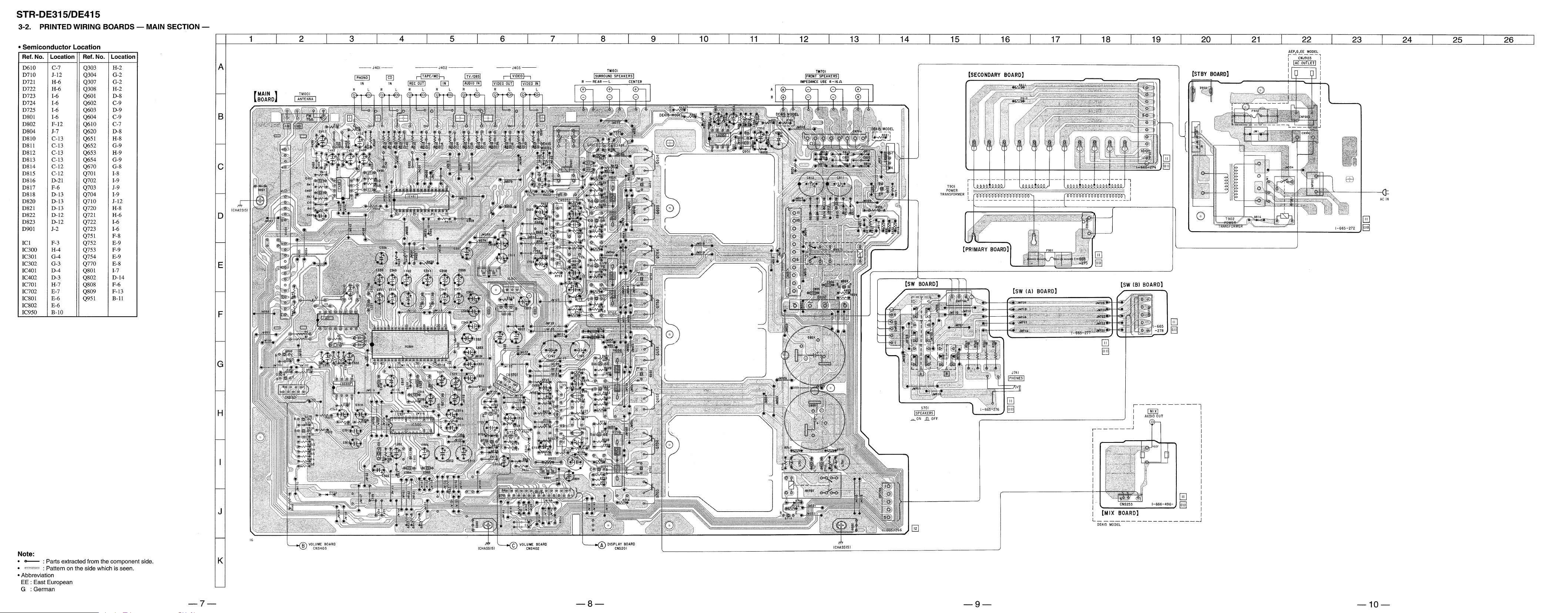
3-2. Printed Wiring Boards — Main Section —························ 7
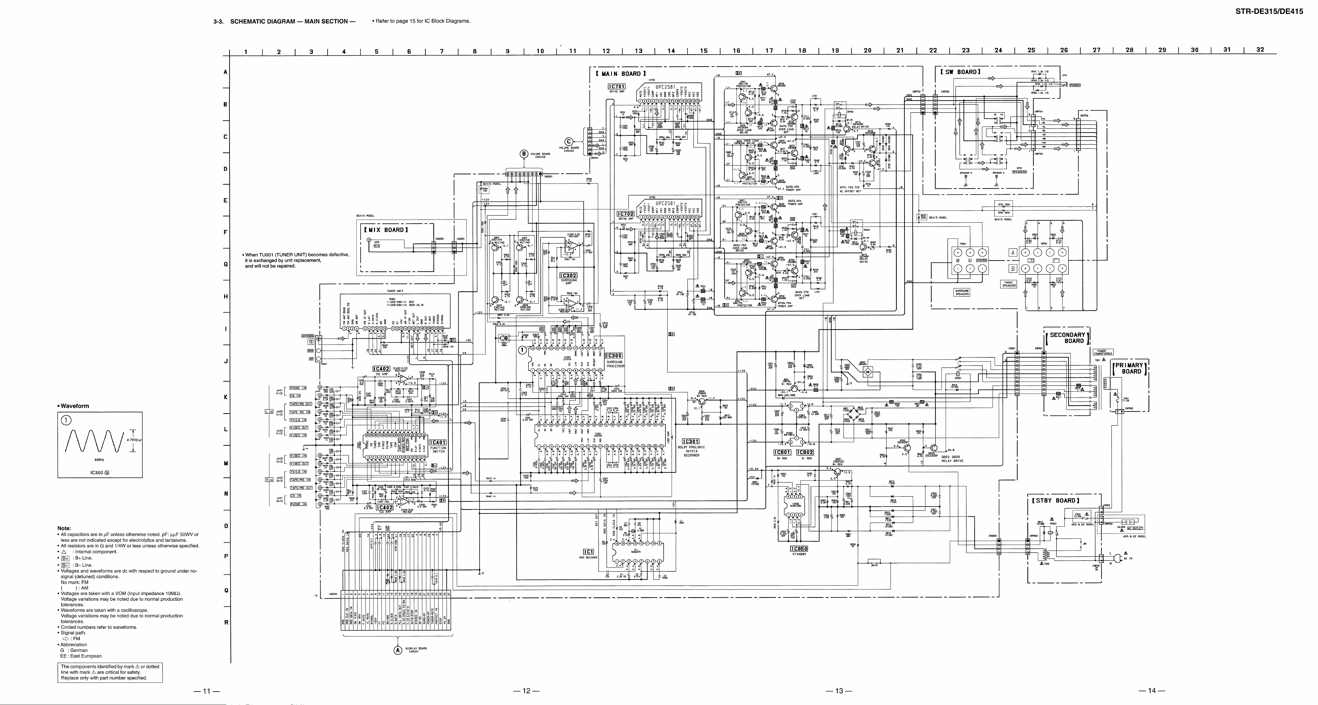
3-3. Schematic Diagram — Main Section —·························· 11
3-4. Schematic Diagram — Display Section —······················ 16
3-5. Printed Wiring Boards — Display Section —·················· 19
4. EXPLODED VIEWS
4-1. Front Panel Section ··························································23
4-2. Chassis Section································································· 24
5. ELECTRICAL PARTS LIST································ 25
Dimensions 430 × 145 × 295mm
Mass (Approx.) 6.4kg
Supplied FM wire aerial (1)
accessories AM loop aerial (1)
Design and specifications are subject to change without notice.
SAFETY-RELATED COMPONENT WARNING!!
Remote controller
(remote) (1)
Size AA (R6) batteries (2)
Scart adaptor (1)
COMPONENTS IDENTIFIED BY MARK ! OR DOTTED LINE WITH
MARK ! ON THE SCHEMATIC DIAGRAMS AND IN THE PARTS
LIST ARE CRITICAL TO SAFE OPERATION. REPLACE THESE
COMPONENTS WITH SONY PARTS WHOSE PART NUMBERS
APPEAR AS SHOWN IN THIS MANUAL OR IN SUPPLEMENTS
PUBLISHED BY SONY.
— 2 —
d
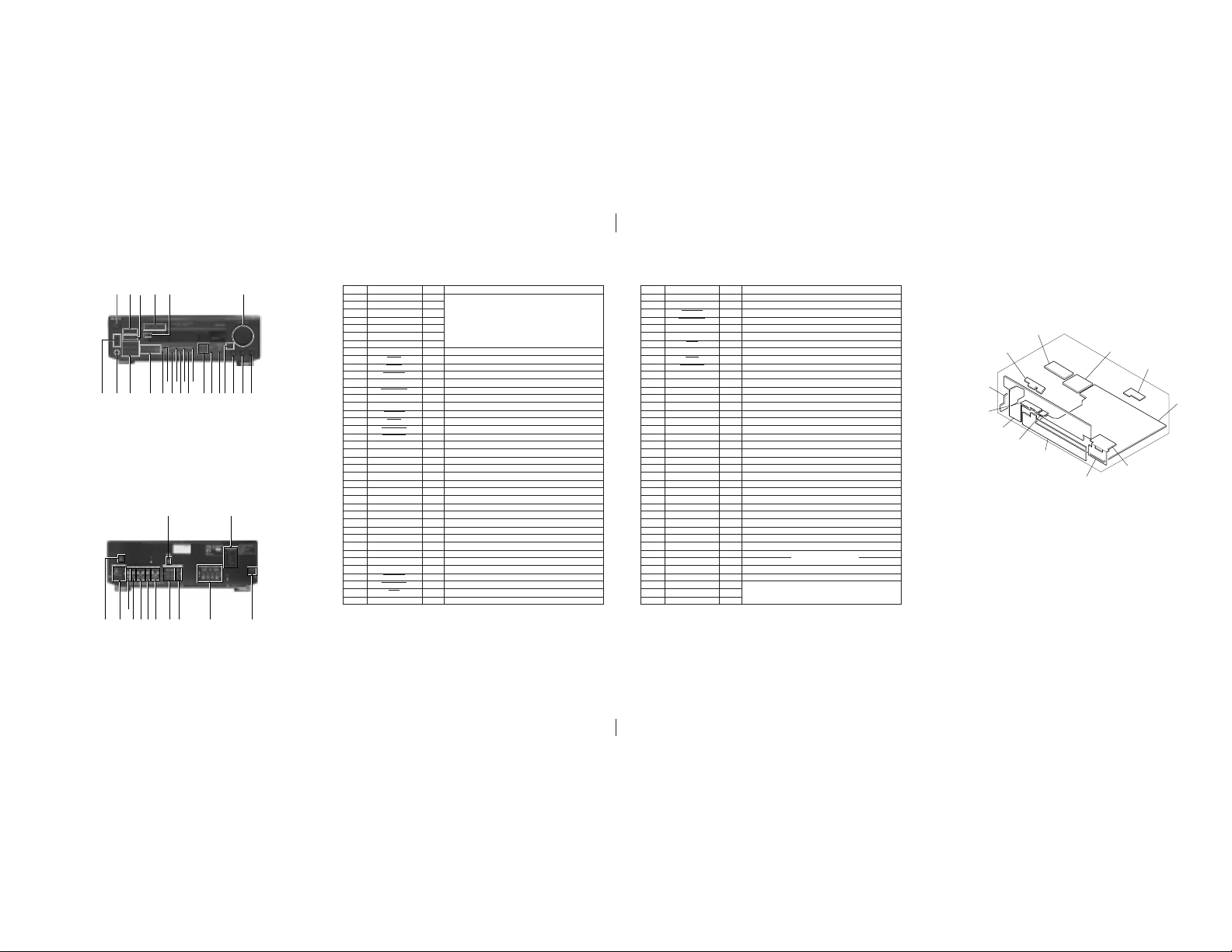
LOCATION AND FUNCTION OF CONTROLS
<FRONT>
2354 6
1
@¢@∞
1 POWER switch
2 CENTER LEVEL +, – buttons
3 REAR LEVEL +, – buttons
4 STANDBY indicator
5 FUNCTION indicators
6 MASTER VOLUME control
7 BALANCE control
8 TREBLE control
9 BASS control
!º BASS BOOST button/indicator
!¡ SURROUND ON/OFF button
!™ MODE button
!£ EFFECT/DELAY TIME, SET UP buttons
<REAR>
!¡
!º!™!£
SECTION 1
GENERAL
!¢!∞!§!¶!•!ª@º
@¡@™@£
!™
!£
!¢ TAPE/MD button
!∞ PHONO button
!§ TV/LD button
!¶ TUNER button
!• VIDEO button
!ª CD button
@º DIRECT button
@¡ SHIFT button
@™ Numeric buttons
@£ Tuner control buttons
@¢ PHONES jack
@∞ SPEAKERS (A/B) buttons
789!º!¡
12
3456789
• IC201 µPD78044FGF-064-3B9
Pin No.
Pin Name
1
DIG7
2
DIG6
3
DIG5
4
DIG4
5
DIG3
6
DIG2
7
DIG1
8
+5V
9
S. CLK
10
S. DATA
11
PLL. DATA
12
S. CE (LC7288)
13
S. CE (LV100)
14
REAR-R
15
BRIDGE
16
PROTECT
17
RESET
18
AUTO-STOP
19
STEREO-IN
20
AVss
21
SP-RY
22
SURR-RY
23
POWER-RY
24
AVss
25
SIGNAL
26
A/D3
27
A/D2
28
A/D1
29
AVDD
30
AV. REF
31
GND
32
NC
33
Vss
34
X1
35
X2
36
IC. MUTE
37
PROLOGIC
38
SIMULATED
39
HALL
40
T. MUTE
SECTION 2
EXPLANATION OF IC TERMINALS
I/O
O
O
O
Fluorescent indicator tube drive.
O
O
O
O
—
Power supply (+5V).
I
System clock.
I
System data.
I
PLL data input from TU001.
O
Chip enable output.
O
Chip enable output.
I
Input for model select.
I
Protector detect input.
I
Protector detect input.
I
System reset terminal.
I
Auto stop detect input.
I
Stereo detect input.
—
Ground.
O
Speaker relay drive.
O
Surround Relay.
O
Power relay drive.
—
Ground.
I
A/D signal input terminal.
I
A/D3 key input terminal.
I
A/D2 key input terminal.
I
A/D1 key input terminal.
—
Power supply (+5V).
—
Reference voltage (+5V).
—
Ground.
—
Not used (Open).
—
Ground.
I
System clock (4.19MHz).
O
System clock (4.19MHz).
O
Mute drive output for µPD2581V (IC701).
O
Plologic LED.
O
CINEMA STUDIO LED.
O
HALL LED.
O
Tuner mute drive output.
Description
Pin No.
SECTION 3
SECONDARY board
KEY board
DIAGRAMS
VR-TONE board
STBY board
MIX board
MAIN boar
VOLUME board
41
VOLUME UP
42
VOLUME DOWN
43
STANDBY
44
SYS. POWER
45
RDS. DATA. IN
46
RDS. CLK. IN
47
48
49
50
POWER SW
51
5.1ch LED
52
53
BASS BOOST
54
FUNC. MUTE
55
SL MUTE
56
VERSION
57
58
59
60
61
SR MUTE
62
63
64
65
66
67
68
69
70
71
72
73
74
75
76
77
78
79
80
STOP
SIRCS
VLOAD
DIG10
DIG9
DIG8
O
Volume up.
O
Volume down.
O
Standby LED drive.
I
System power ON/OFF.
I
RDS data input.
I
RDS clock input.
I
Stop signal input from NJM2103D (IC950).
—
Vss
+5V
K14
K13
K12
K11
S15
S14
S13
S12
S11
S10
S9
S8
S7
S6
S5
S4
S3
S2
S1
Ground.
I
Sircs signal input.
I
Power switch input terminal.
—
5.1ch LED drive.
—
Power supply (+5V).
I
Bass boost LED drive.
O
Line mute drive.
O
SL mute drive.
I
Input for model select.
I
Key in 4.
I
Key in 3.
I
Key in 2.
I
Key in 1.
O
SR mute drive.
O
Key out 15.
O
Key out 14.
O
Key out 13.
O
Key out 12.
O
Key out 11.
O
Key out 10.
O
Key out 9.
O
Key out 8.
O
Key out 7.
—
Connect to –24V.
O
Key out 6.
O
Key out 5.
O
Key out 4.
O
Key out 3.
O
Key out 2.
O
Key out 1.
O
O
Fluorescent indicator tube drive.
O
I/O
Pin Name
Description
Fluorescent indicator tube drive.
Fluorescent indicator tube drive.
3-1. CIRCUIT BOARDS LOCATION
PRIMARY board
SW board
SP SW (A) board
DISPLAY board
SP SW (B) board
1 WOOFER
2 AC OUTLET (EXCEPT UK)
3 AC power cord
4 FRONT SPEAKERS (A/B)
5 SURROUND SPEAKERS (CENTER)
6 SURROUND SPEAKERS (REAR)
7 VIDEO
8 TV/LD
9 TAPE/MD
!º CD
!¡ PHONO
!™ ANTENNA (FM/AM)
!£ SIGNAL GND
— 3 — — 4 — — 5 — — 6 —
 Loading...