

Sony STR-DB790,STR-DA1000ES Operating Instructions Manual
4-246-802-16(!)
SON'Y:
FM Stereo
FM/AM Receiver
Operating Instructions
Owner's Record
The model and serial numbers are located on the rear of the unit. Record the serial
nmnber in the space provided below. Refer to them whenever you call upon your
Sony dealer regarding this product.
Model No. Serial No.
STR-DA IO00ES
STR-DB 790
@2003 Sony Corporation
To prevent fire or shock hazard, do not
expose the unit to rain or moisture.
To prevent fire do not cove! the ventilation of tile
appalalus with news papers, table-cloths cmtains, etc.
And don't place lighted candles on the apparatus.
To prevent fire or sbock bazard do not place objects
filled with ligfids sucb as vases, on the apparatus
Do not install file appliance m a confined spacesucb as a bookcase or built-in cabinet
I_@ Don't fllww away batteries with
geneial bouse waste: dispose of
then] correctly as chemical waste
This symbol is intended to alert
the user to the presence of
tminsulated "dangerous voltage"
witbin the pro&rat's enclosme
that ]nay be of sufficient
magnitude to constitute a risk of
electric shock to pmsons
This symbol is intended to alert
the user to the presence of
important operating and
maintenance (servicing)
instructions in the literatm-e
accompanying the appliance.
WARNING
Tiffs equipment has been tested and fotmd to comply with tile
limits for a Class B digital device, pursuant to Part 15 of the
FCC Rules These tinffts are designed to p:ovide reasonable
protection against hamffu111ire:fe:_llce in a residential
installation This eqmpmem gene:ates, uses, and can radiate
radio fiequency energy and, if not installed and used in
accordance with tbe insm:ctions, ::my cause harnfful
interference to radio con:amuffcations However, tbere is no
guaramee that interference will not occm- in apagicular
installation. If tiffs equipment does cause bmmfid
interference to radio or television reception, wlffch can be
deternm:ed by ttmffng the equiplnent off and on. the user is
encouraged to ri?"to conect tbe interference by one or n:ore
oftbe following measures:
Reorient or relocate tbe receiving antenna.
Increase tbe separation between tbe equipment and
receives
Connect tbe equipment into an outlet on a circuit
different flora that to whicb tbe receiver is
connected.
Consult the dealer or an experienced radio/TV
teclmician tbr belp
CAUTION
You are cautioned that any changes or modification not
expressly approved in tbis manual could void your
anthority to operate this equipment.
Note to CATV system installer:
Tiffs reminde_ is provided to call CATV system
installer's atWntion to ,_ticle 820-40 oftbe NEC that
provides guidelines for proper grom_ding and, in
partictflar, specifies that tbe cable ground shall be
connected to tbe grom_ding system of the building, as
close to tbe point of cable entry as practical.
For customers in Canada
CAUTION
TO PREVENT ELECTRIC SHOCK, DO NOT USE
THIS POLARIZED AC PLUG WITH AN
EXTENSION CORD, RECEPTACLE OR OTHER
OUTLET LSXTLESS THE BLADES CAN BE FULLY
INSERTED TO PREVENT BLADE EXPOSURE
Except for European model
ENERGY STAR "_ is a U.S.
registered mark. As an ENERGY
STAR _"partner Sony Corporation
bas detem_ined tbat this product
meets the ENERGY STARg'
guidelines for energy efficiency.
2 GB
About This Manual
• The instluctions in this manual are for nlodel STR-
DA1000ES and STR-DB790. Check yore model
munber by looking at the lower right comer of the
fiont panel In this manual, STR-DAI000ES is used
for illustration pul_oses unless stated othelavise. Any
diffel ence in operation is clearly indicated in the text,
for example, "STR-DAIOOOES only".
• The insUuctions in this mamlal describe file controls
on the receiver. You can also use the conUols on the
supplied remote if they have the same or similar
names as those on the receiver For details on the use
of your remote:
STR-DAI000ES:
RM-LG 112
STR-DB790:
RM-PP412
See the separate operating instructions supplied with
the remote.
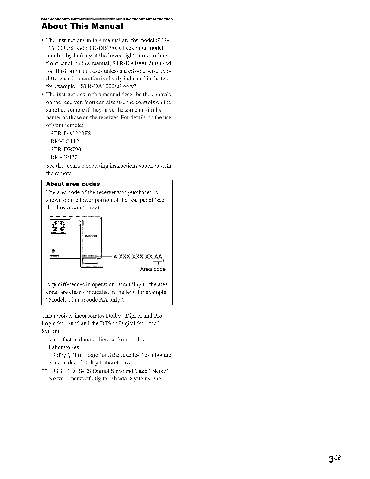
About area codes
The area code of the receive: you p:_chased is
shown on the lowel portion of the rea: panel (see
the illustration below).
4-XXX-XXX-XX A_
Area cede
Any differences in operation, according to the area
code, are clearly indicated in the text, for example,
"Models of area code ,43_ only".
This receiver incoiporates Dolby* Digital and Pro
Logic SmTo:md and the DTS** Digital SuiTound
System
* Manufactmed under license flora Dolby
Laboratories.
"Dolby", "Pro Logic" and the double-D symbol are
trademarks of Dolby Laboratories.
** "DTS", "DTS-ES Digital SmTotmd", and "Neo:6"
are uademarks of Digital Theater Systems, Inc
3 GB
Getting Started
l : Check how to hookup your
components ....................................... 6
1a: Connecting components with
digital audio output jacks ........... 8
lb: Connecting components with
nmlti channel output jacks ........ 11
le: Connecting components with only
analog audio jacks .................... 13
2: Connecting the antennas ................... 15
3: Connecting speakers ......................... 16
4: Connecting the AC power cord ........ 19
5: Setting up the speakers ..................... 20
6: Adjusting the speaker levels and
balance ............................................ 23
TEST TONE
Amplifier Operation
Selecting the component ....................... 24
Listening to nmlti channel sound .......... 24
MULTI CH IN
Listening to FMAM radio .................... 25
Storing FM stations automatically ........ 26
AUTOBETICAL
(Models of area code CEL, CEK
only)
Presetting radio stations ........................ 26
Using the Radio Data System (RDS).... 27
(Models of area code CEL, CEK
only)
(?hanging the display ............................. 29
About the indications in the display ...... 30
Enjoying Surround Sound
Using only the fi'ont speakers ............... 31
Enjoying higher fidelity sound .............. 31
AUTO FORMAT DIRECT
Selecting a sound field .......................... 32
Selecting the sun'ound back decoding
mode ............................................... 34
SURR BACK DECODING
Advanced Adjustments and
Settings
Switching the audio input mode for digital
components ..................................... 36
INPUT MODE
Customizing sound fields ..................... 36
Adjusting the equalizer ......................... 38
Advanced settings ................................. 38
Other Operations
Naming preset stations and inputs ........ 42
Using the Sleep Timer .......................... 43
Selecting the speaker system ................ 43
Recording ............................................. 44
CONTROL AIlI Control System ........ 45
Additional Information
Precautions ........................................... 46
Troubleshooting .................................... 47
Specifications ....................................... 49
List of button locations and reference
pages ............................................... 52
Index ..................................................... 54
4 GB

5G8
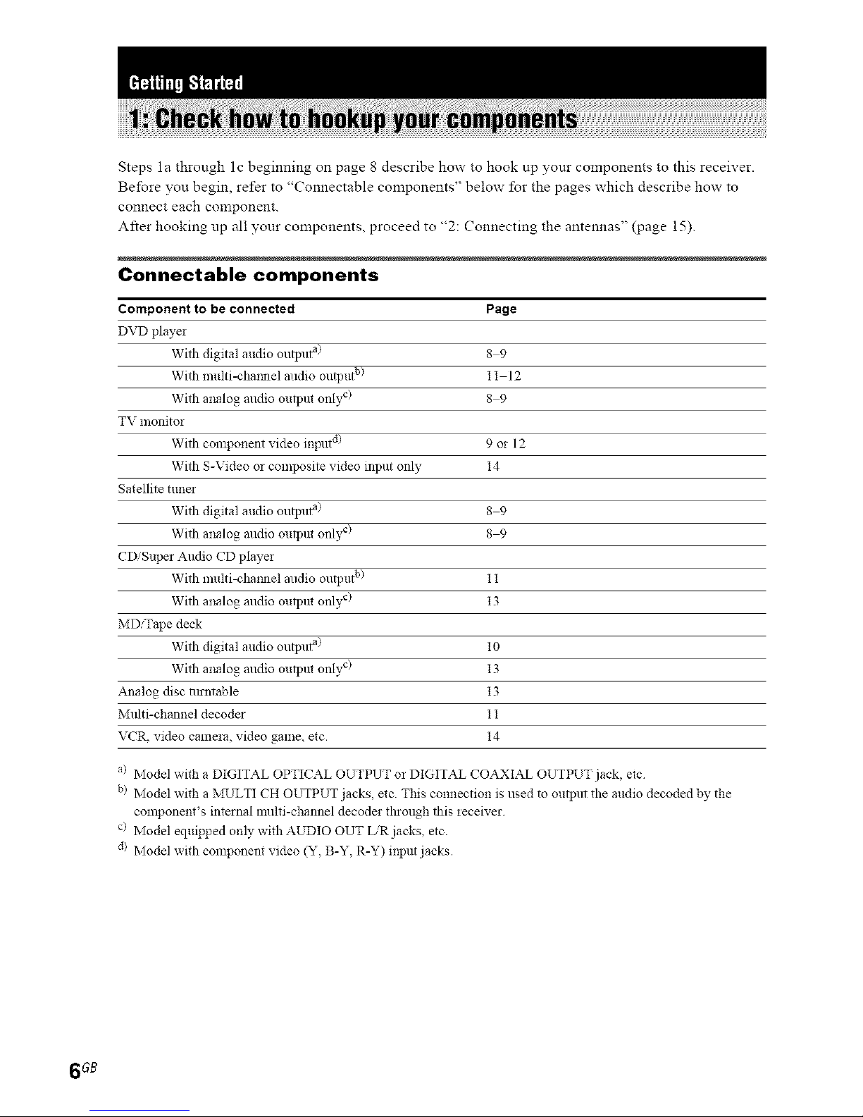
Steps la through lc beginning on page 8 describe how to hook up your components to this receiver.
Before you begin, refer to "Connectable components" below lbr the pages which describe how to
connect each component.
After hooking up all yonr components, proceed to "2: Connecting the antennas" (page 15).
Connectable components
Component to be connected Page
DVD player
With digital audio output a) 8 9
With multi-cha i?_nelalldio output b/ 11 12
With analog alldio output only c/ 8 9
TV monitor
With component video input d/ 9 or 12
With S-Video or composite video input only 14
Satellite tune_
With digital audio output a) 8 9
With analog alldio output only c/ 8 9
CDiSuper Audio CD player
With multi-chaimel audio output b/ 11
With analog mldio output only c/ 13
MDiTape deck
With digital audio output a/ 10
With analog mldio output only c/ 13
Analog disc lurntable 13
Multi-channel decoder 11
VCR, video camera, video game, etc. 14
a/ Model with a DIGITAL OPTICAL OUTPUT or DIGITAL COAXIAL OUTPUT jack, etc
b) Model with a MULTI CH OUTPUT jacks, etc. This connection is used to output the audio decoded by the
component's internal nmlti-channel decoder through this receiver
c/ Model equipped only with AUDIO OUT LiR jacks, etc.
d/ Model with component video (Y, B-Y, R-Y) input jacks.
6 6B
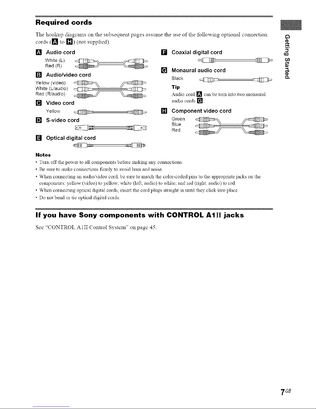
Required cords
The hookup diagrams on the subsequent pages assume the use of the %llowing optiona! connection
cords ([] to I_1) (not supplied).
[] Audio cord
White (L)
Red (R)
[] Audio/video cord
Yellow (video)
White (L/audio)
Red (R/audio)
[] Video cord
Yellow @
[] S-video cord
[] Optical digital cord
@ @
Notes
• Tmn off the power te all components betbre making any connections
• Be sure to make connections firefly to avoid lunn and noise
• When connecting an audio/video cord, be sme to match the color-coded pins to the appropriate jacks on the
components: yellow (video) to yellow; white (left, audio) to white: and red (right, audio) to red
• When connecting optical digital cords, insert the cord plugs straigN in until they click into place
• Do not bend or tie optical digital cords.
[] Coaxial digital cord
[] Monaural audio cord
Black @
Tip
Audio cold [] can be tom into iwo monamal
attdio cords [_l.
[] Component video cord
Green
Blue
Red
If you have Sony components with CONTROL AIII jacks
See "CONTROL AIII Contro! System" on page 45.
7 GB
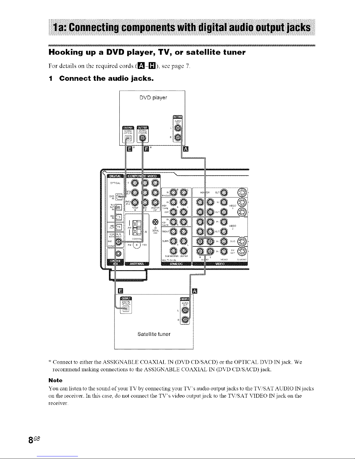
Hooking up a DVD player, TV, or satellite tuner
For details on the required cords ([] []), see page 7.
1 Connect the audio jacks.
DVD player
)@,,,o,@@
?
.... @ (,,
Satellite tuner
* Connect to either the ASSIGNABLE COAXIAL IN (DVD CDiSACD) or the OPTICAL DVD IN jack We
recommend making connections to the ASSIGNABLE CO,_XL_L IN (DVD CDiSACD) jack.
Note
You can listen to the sotmd of your TV by connecting _ur TV's audio output jacks to the TV,'SAT AUDIO IN jacks
on the receive!. In this case, do not connect the TV's video oui]Jut jack to the TViSAT VIDEO IN jack on the
receiver.
8GB
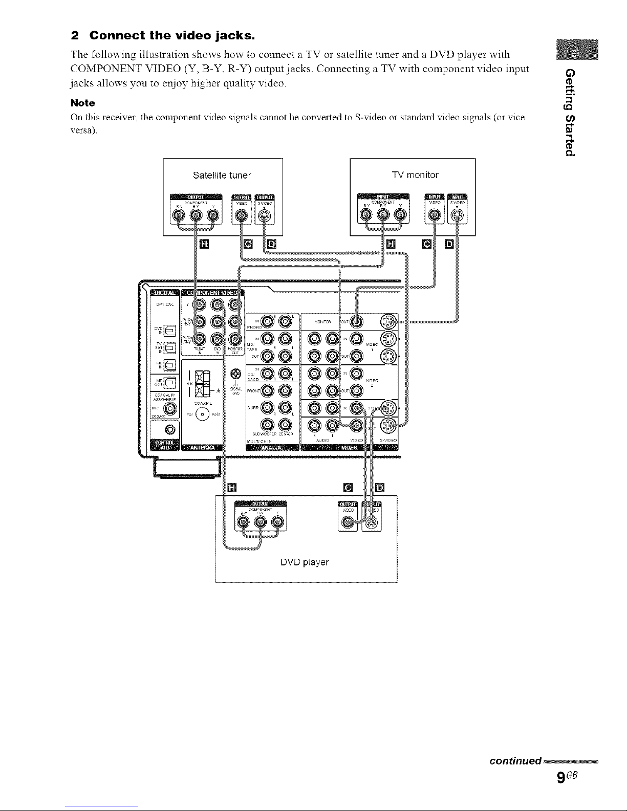
2 Connect the video jacks.
The _llowing illustration shows how to connect a TV or satellite tnner and a DVD player with
COMPONENT VIDEO (Y, B-Y, R-Y) ontput jacks. Connecting a TV with component video inpnt O
.jacks allows yon to er_joy higher qnality video.
Note (_
On this ieceiver, the component video signals cannot be conve2ted to S-video 02standard video signals (02vice
versa). _"
Satellite tuner TV monitor
DVD player
con_nued_
9G8
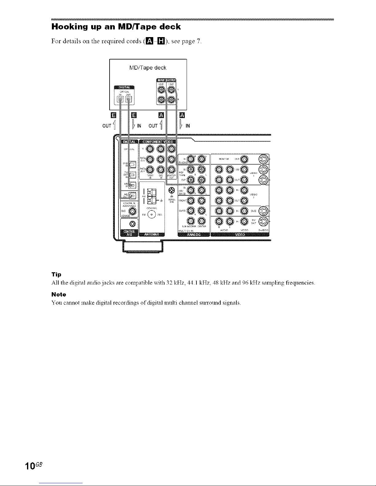
Hooking up an MD/'rape deck
For details on the reqmred cords (_'1 []), see page 7.
[]
OUT
MD/Tape deck
Tip
All the digital audio jacks are compatible with 32 kHz, 44 1kHz, 48 kHz and 96 kHz sampling tiequencies.
Note
You cannot make digital recordings of digital multi channel surrolmd signals
10GB
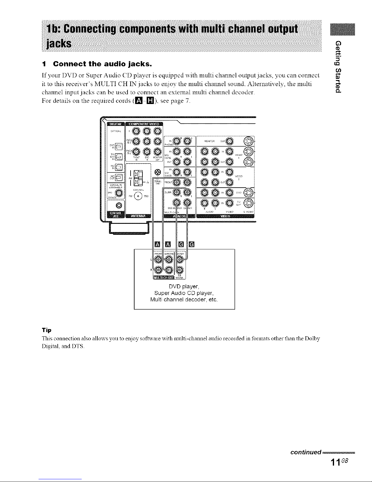
1 Connect the audio jacks.
If yonr DVD or Snper Audio (D player is equipped with nmhi channel outpnt jacks, you can connect
it to this receiver's MULTI CH IN jacks to er_ioy the nmlti channel sound. AhernatiYely, the multi
channel input jacks can be used to connect an external multi channel decoder.
For details on the required cords ([] 1_1), see page 7.
g)
DVD player,
Super Audio CD player,
MuIti channel decoder, etc.
Tip
This connection also allows you to enjoy softwaie with multi-chamM audio recoided in tbrmats other than the Dolby
Digital. and DTS.
continued_
11GB
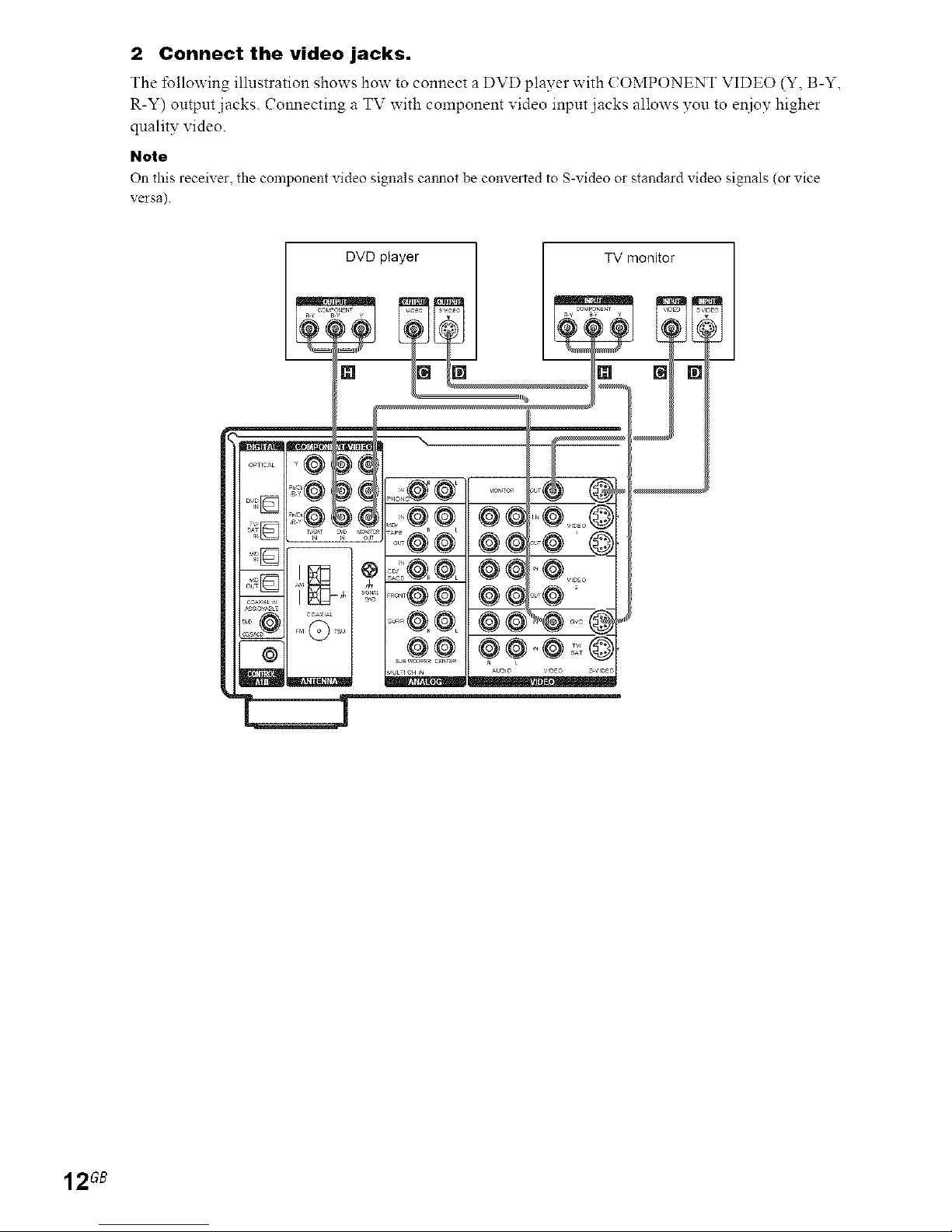
2 Connect the video jacks.
The tbllowing illnstration shows how to connect a DVD player with ( OMPONENT VIDEO (Y, B-Y,
R-Y) output jacks. Connecting a TV with component video input jacks allows you to e11ioyhigher
quality video.
Note
On this receiver, the component video signals caimot be converted to S-video or standard video signals (or vice
versa)
DVD player TV monitor
12GB
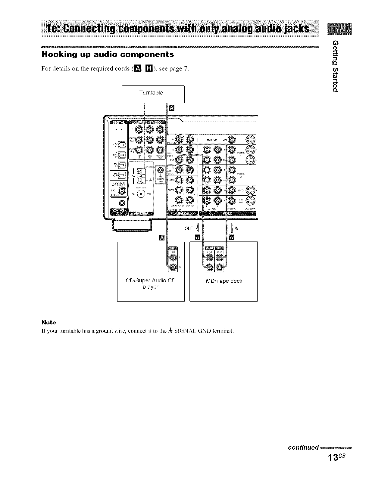
Hooking up audio components
For details on the required cords (1_ []), see page 7.
Turntable
O_TIC_L
[]
NIL
CD/Super Audio CD
player
0°,4 tl.
[] []
@1(@
NI_
MD/Tape deck
Note
Ifyourmrntable hasa ground wire, connectitto the • SIGNAL GND terminal.
con_nued_
13G8
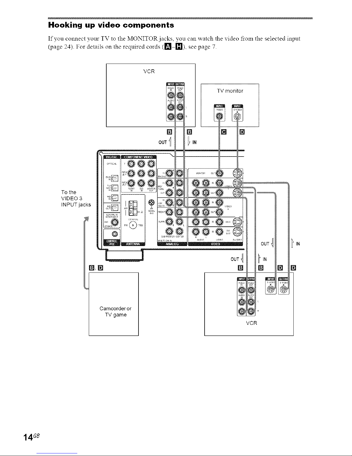
Hooking up video components
If you connect your TV to the MONITOR jacks, you can watch the video from the selected inpnt
(page 24). For details on the required cords (1_ I_), see page 7.
VCR
To the
VIDEO 3 'it[_
INPUT jacks j;;_
@
TV monitor
[] [] I []
OUT I ilN
Camcorder or
TV game
OUT
[]
VCR
[]
14GB
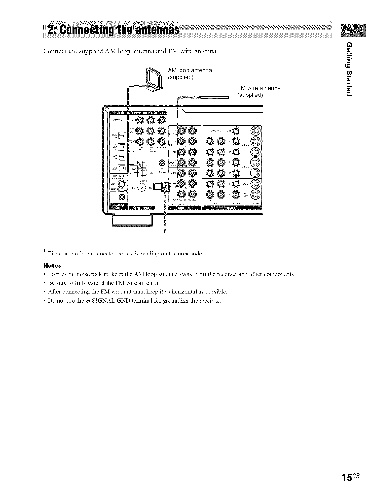
Connect the supplied AM loop antenna and FM wire antenna.
I,Q
AM loop antenna
(supplied) _"
FM wire antenna
(supplied)
* The shape of the connector varies depending on the area code
Notes
• To prevent noise pickup, keep the AM loop antenna away fimn file receiver and other components.
• Be sure to fiflly extend the FM wire antenna.
• After connecting the FM wire antenna, keep it as horizontal as possible
• Do not use the _ SIGNAL GND terminal for grounding the receiver
15GB
Connect your speakers to the receiver. This receiver allows you to use a 7.1 channel system (STR-
DA 1000ES) or 6.1 channel speaker system (STR-DB790).
To fully enjoy theater-like mnlti channel surround sotmd requires five speakers (two front speakers, a
center speaker, and two surround speakers) and a sub woofer (5.1 channel).
You can enjoy high fidelity reproduction of DVD software recorded in the Surround EX format ifvou
connect one additional snrround back speaker (6.1 channel) or two snrround back speakers (7.1
channel, STR-DA1000ES only) (see "Selecting the surround back decoding mode" on page 34).
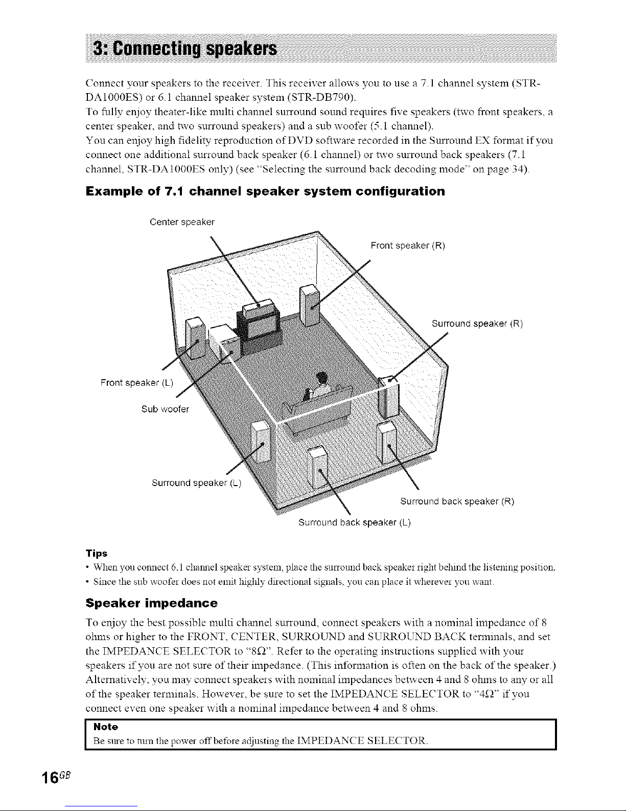
Example of 7.1 channel speaker system configuration
Center speaker
Frontspeaker(R)
Surround speaker(R)
Frontspeaker(L)
Sub woofer
Surround speaker (L)
Surround back speaker (R)
Surround back speaker (L)
Tips
• When you connect 6.1 chatmel speaker system, place the surround back speaker right behind the listening position.
• Since the sub woofer does not emit highly directional signals, you can place it wherever you want.
Speaker impedance
To enjoy the best possible muhi channel surround, connect speakers with a nominal impedance of 8
ohms or higher to the FRONT, CENTER, SURROLTND and SURROUND BACK terminals, and set
the IMPEDANCE SELECTOR to "8_Y'. Refer to the operating instructions supplied with your
speakers if you are not sure of their impedance. (This information is often on the back of the speaker.)
Alternatively, you may connect speakers with nominal impedances between 4 and 8 ohms to any or all
of the speaker terminals. However, be sure to set the IMPEDANCE SELECTOR to "4_-)" ifvou
connect even one speaker with a nominal impedance between 4 and 8 ohms.
Note
Be stue to turn the powe_ off be_bre adjusting the IMPEDANCE SELECTOR.
16GB
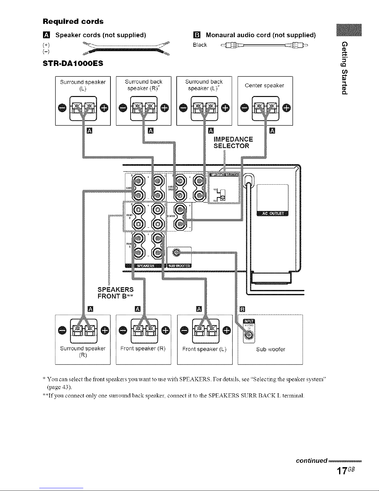
Required cords
[] Speaker cords (not supplied)
S'FR.DAIOOOES
[] Monaural audio cord (not supplied)
Black @
Surround speaker Surround back Surround back
(L) speaker (R) speaker (L) Center speaker
[] [] []
IMPEDANCE
SELECTOR
[] []
tr_d_k? Front speaker (R)
[] []
Frontspeaker(L) Sub woofer
* You can select the front speakers you want to use with SPEAKERS For details, see '+Selectingtile speaker system"
(page 43).
+,
' If you connect only one sunotmd back speaker, connect it to the SPEAKERS SURR BACK L terminal.
re,
e,
continued_
17G8
 Loading...