

Page 1

4-246-802-17(1)
FM Stereo
FM/AM Receiver
Operating Instructions
Owner’s Record
The model and serial numbers are located on the rear of the unit. Record the serial
number in the space provided below. Refer to them whenever you call upon your
Sony dealer regarding this product.
Model No.
Serial No.
STR-DA1000ES
STR-DB790
©2003 Sony Corporation
Page 2
WARNING
To reduce the risk of fire or electric
shock, do not expose this apparatus to
rain or moisture.
To prevent fire, do not cover the ventilation of the
apparatus with news papers, table-cloths, curtains, etc.
And don’t place lighted candles on the apparatus.
To prevent fire or shock hazard, do not place objects
filled with liquids, such as vases, on the apparatus.
Do not install the appliance in a confined space,
such as a bookcase or built-in cabinet.
Don’t throw away batteries with
general house waste; dispose of
them correctly as chemical waste.
For customers in the United States
This symbol is intended to alert
the user to the presence of
uninsulated “dangerous voltage”
within the product’s enclosure
that may be of sufficient
magnitude to constitute a ri sk of
electric shock to persons.
This symbol is intended to alert
the user to the presence of
important operating and
maintenance (servicing)
instructions in the literature
accompanying the appliance.
WARNING
This equipment has been tested and found to comply with the
limits for a Class B digital device, pursuant to Part 15 of the
FCC Rules. These limits are designed to provide reasonable
protection against harmful interference in a residential
installation. This equipment generates, uses, and can radiate
radio frequency energy and, if not installed and used in
accordance with the instructions, may cause harmful
interference to radio communications. However, there is no
guarantee that interference will not occur in a particular
installation. If this equipment does cause harmful
interference to radio or television reception, which can be
determined by turning the equipment off and on, the user is
encouraged to try to correct the interference by one or more
of the following measures:
– Reorient or relocate the receiving antenna.
– Increase the separation between the equipment and
receiver.
– Connect the equipment into an outlet on a circuit
different from that to which the receiver is
connected.
– Consult the dealer or an experienced radio/TV
technician for help.
CAUTION
You are cautioned that any changes or modification not
expressly approved in this manual could void your
authority to operate this equip ment.
Note to CATV system installer:
This reminder is provided to call CATV system
installer’s attention to Article 820-4 0 of the NEC that
provides guidelines for proper grounding and, in
particular, specifies that the cable ground shall be
connected to the grounding system of the building, as
close to the point of cable entry as practical.
For customers in Canada
CAUTION
TO PREVENT ELECTRIC SHOCK, DO NOT USE
THIS POLARIZED AC PLUG WITH AN
EXTENSION CORD, RECEPTACLE OR OTHER
OUTLET UNLESS THE BLADES CAN BE FULLY
INSERTED TO PREVENT BLADE EXPOSURE.
Except for European model
ENERGY STAR® is a U.S.
registered mark. As an ENERGY
STAR® partner, Sony Corporatio n
has determined that this product
meets the ENERGY STAR®
guidelines for energy efficiency.
GB
2
Page 3
About This Manual
• The instructions in this manual are for model STRDA1000ES and STR-DB790. Check your model
number by looking at the lower right corner of the
front panel. In this manual, STR-DA1000ES is used
for illustration purposes unless stated otherwise. Any
difference in operati on is clearly indicated in th e text,
for example, “STR-DA1000ES only”.
• The instructions in this manual describe the controls
on the receiver. You can also use the controls on the
supplied remote if they ha ve th e sam e or si milar
names as those on the receiver. For details on the use
of your remote:
– STR-DA1000ES:
RM-LG112
–STR-DB790:
RM-PP412
See the separate operating instructions supplied with
the remote.
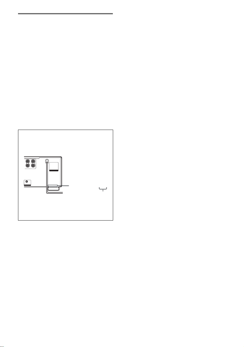
About area codes
The area code of the receiver you purchased is
shown on th e lo wer portion of the rear panel ( see
the illustration below).
LR
+
–
SURROUND BACK
CENTER
AC OUTLET
SUB WOOFER
4-XXX-XXX-XX AA
Area code
Any differences in operation, according to th e area
code, are clearly indicated in the text, for example,
“Models of area code AA only”.
This receiver incorporates Dolby* Digital and Pro
Logic Surround and the DTS** Digital Surrou nd
System.
* Manufactured under license fr om Dol by
Laboratories.
“Dolby”, “Pro Logic” and the double-D symbol are
trademarks of Dolby Laboratories.
**“DTS”, “D TS - ES Dig ital Surround”, and “Neo:6”
are trademarks of Digital Theater Sy st em s , I nc .
GB
3
Page 4

Table of Contents
Getting Started
1: Check how to hookup yo ur
components.......................................6
1a: Connecting components with
digital audio output jacks ...........8
1b: Connecting components with
multi channel output jacks........11
1c: Connecting compon ents with only
analog audio jacks....................13
2: Connecting the antennas...................15
3: Connecting speakers .........................16
4: Connecting the AC power cord ........19
5: Setting up the speakers .....................20
6: Adjusting the speaker levels and
balance............................................ 23
— TEST TONE
Amplifier Operation
Selecting the component.......................24
Listening to multi channel so un d..........24
— MULTI CH IN
Listening to FM/AM radio....................25
Storing FM stations automatically........26
— AUTOBETICAL
(Models of area code CEL, CEK
only)
Presetting radio stations........................26
Using the Radio Data System (RDS)....27
(Models of area code CEL, CEK
only)
Changing the display.............................29
About the indications in the display......30
Advanced Adjustments and
Settings
Switching the audio input mode for digital
components..................................... 36
— INPUT MODE
Customizing sound fields.....................36
Adjusting the equalizer.........................38
Advanced settings.................................38
Other Operations
Naming preset stations and inputs........ 42
Using the Sleep Timer..........................43
Selecting the speaker system................ 43
Recording .............................................44
CONTROL A1II Control System........ 45
Additional Information
Precautions ...........................................46
Troubleshooting....................................47
Specifications .......................................49
List of button locations and reference
pages...............................................52
Index.....................................................54
Enjoying Surround Sound
Using only the front speakers...... .........31
Enjoying higher fidelity sound..............31
— AUTO FORMAT DIRECT
Selecting a sound field..........................32
Selecting the surround back decoding
mode ...............................................34
— SURR BACK DECODING
GB
4
Page 5

GB
5
Page 6

Getting Started
1: Check how to hookup your components
Steps 1a through 1c beginning on page 8 describe how to hook u p your components to this r eceiver.
Before you begin, refer to “Connectable components” below for the pages which describe how to
connect each component.
After hooking up all your components, proceed to “2: Connecting the antennas” (page 15).
Connectable components
Component to be connected Page
DVD player
With digital audio outpu t
With multi-channel audi o output
With analog audio output only
TV monitor
With component video input
With S-Video or composite video inp ut onl y 14
Satellite tuner
With digital audio outpu t
With analog audio output only
CD/Super Audio CD player
With multi-channel audi o output
With analog audio output only
MD/Tape deck
With digital audio outpu t
With analog audio output only
Analog disc turntable 13
Multi-channel decoder 11
VCR, video camera, video game, etc. 14
a)
Model with a DIGITAL OPTICAL OUTPUT or DIGITAL COAXIAL OUTPUT jack, etc.
b)
Model with a MULTI CH OUTPUT jacks, etc. This connection is used to output the audio de co de d by the
component’s internal multi-channel decoder through this receiver.
c)
Model equipped only with AUDIO OUT L/R jac ks, etc.
d)
Model with component video (Y, B-Y, R-Y) input jacks.
a)
b)
c)
d)
a)
c)
b)
c)
a)
c)
8–9
11–12
8–9
9 or 12
8–9
8–9
11
13
10
13
GB
6
Page 7
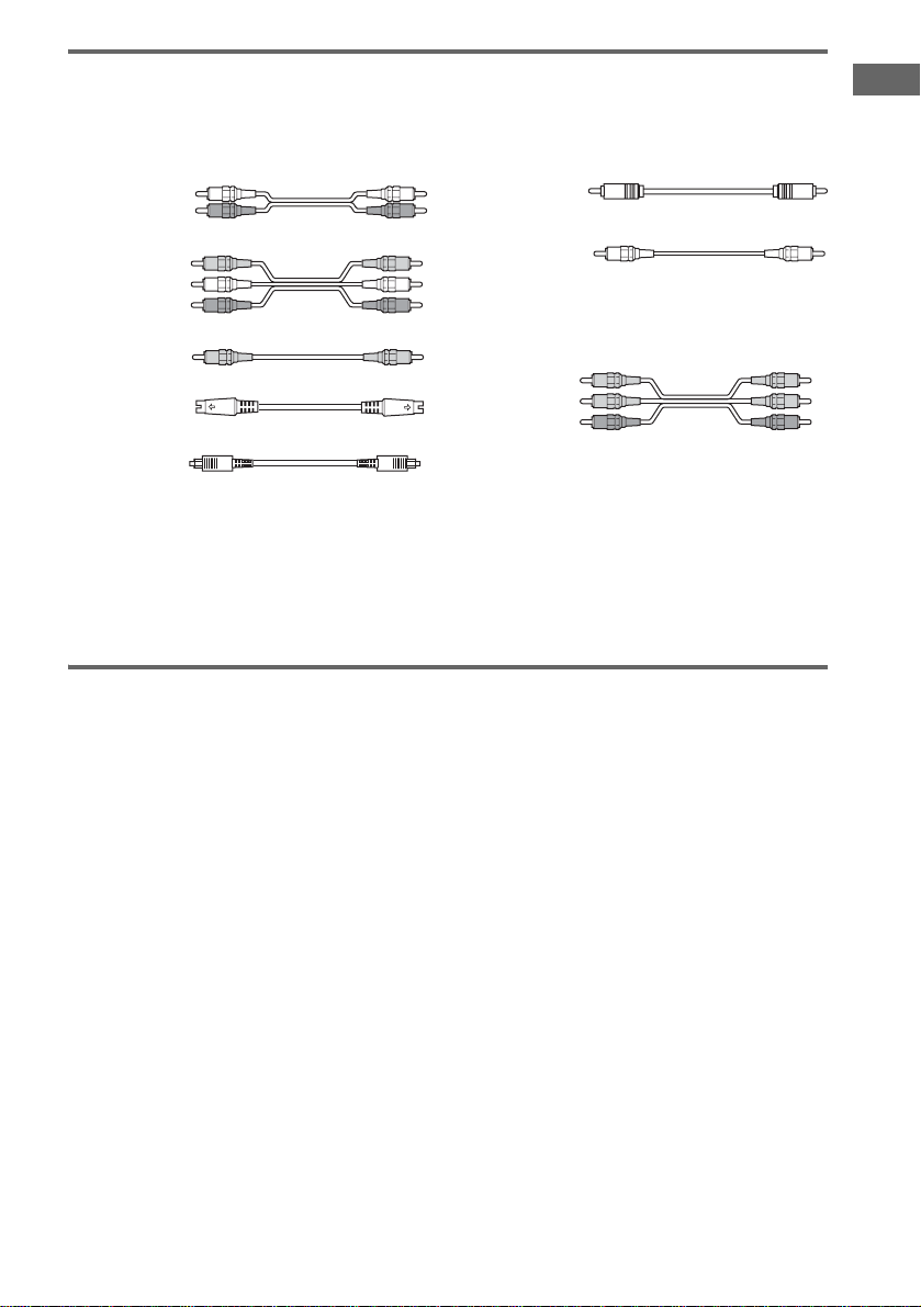
Required cords
The hookup diagrams on the subsequent pages assume th e use of the followin g optional connecti on
cords (A to H) ( not supplied).
A Audio cord
White (L)
Red (R)
B Audio/video cord
Yellow (video)
White (L/audio)
Red (R/audio)
C Video cord
Yellow
D S-video cord
F Coaxial digital cord
G Monaural audio cord
Black
Tip
Audio cord A can be torn into two monaural
audio cords G.
H Component video cord
Green
Blue
Red
E Optical digital cord
Notes
• Turn off the power to all components before making any connections.
• Be sure to make connections firmly to avoid hum and noise.
• When connecting an audio/video cord, be sure to match the color-coded pins to the appropriate jacks on the
components: yellow (video ) to yel low; white (left, audio) to white; and red (right, audio) to red.
• When connecting optical digital cords, insert the cord plugs straight in until they click into place.
• Do not bend or tie optical digital cords.
If you have Sony components with CONTROL A1II jacks
Getting Started
See “CONTROL A1II Control System” on page 45.
GB
7
Page 8
.
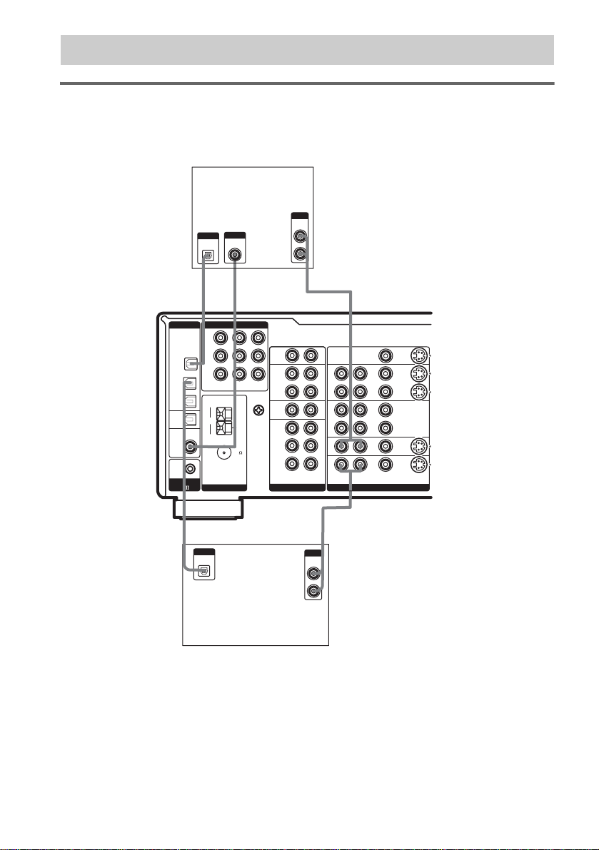
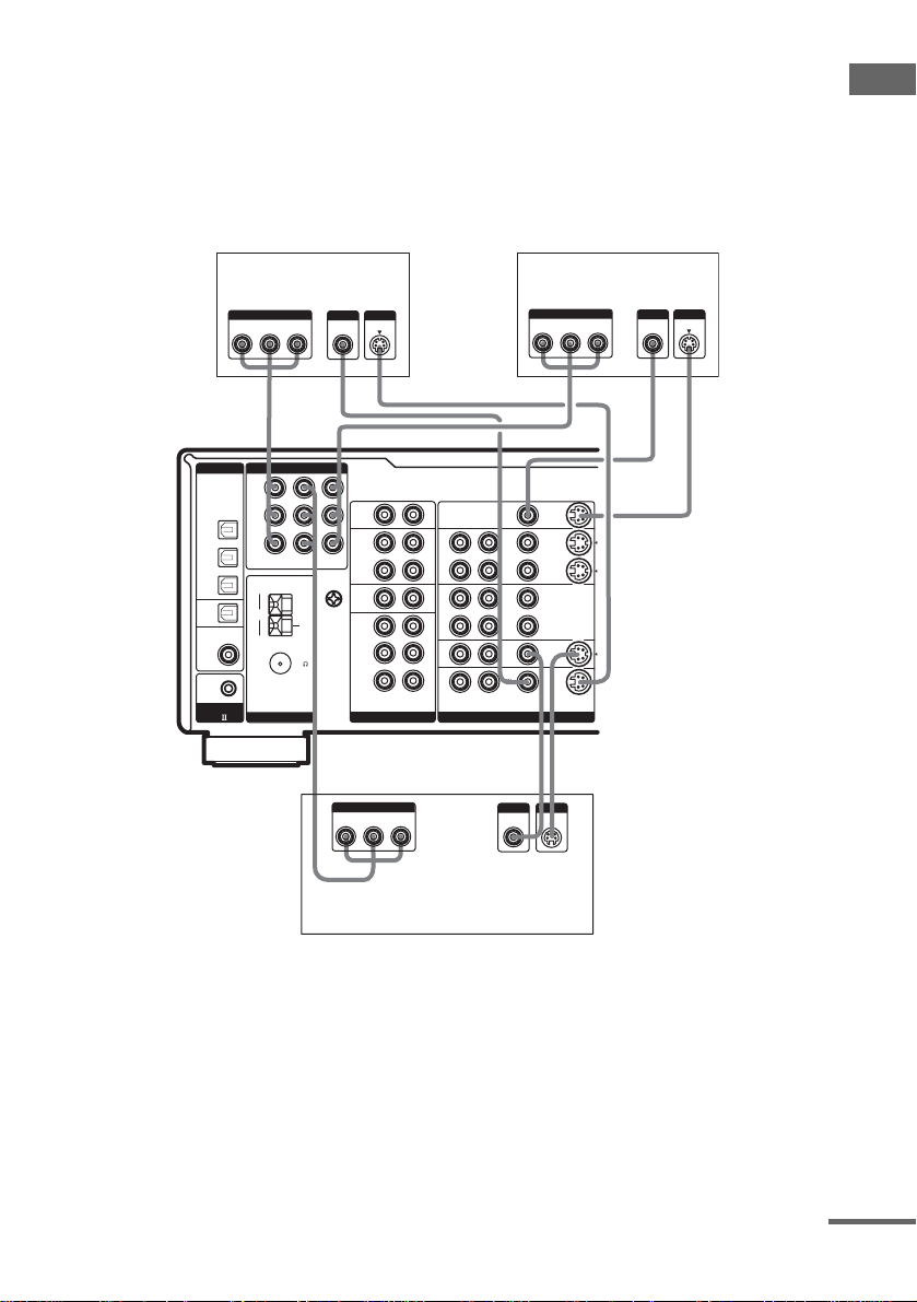
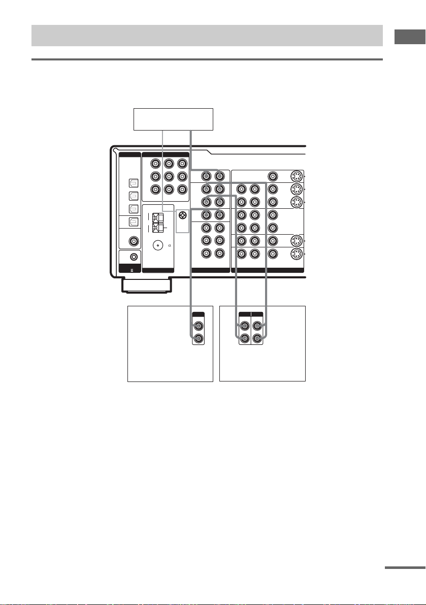
1a: Connecting components with digital audio output jacks
Hooking up a DVD player, TV, or satellite tuner
For details on the required cords (A–H), see page 7.
1 Connect the audio jacks.
DVD player
OUTPUT
AUDIO
OUT
OUTPUT
OUTPUT
DIGITAL
DIGITAL
COAXIAL
OPTICAL
*
E
DIGITAL COMPONENT VIDEO
Y
OPTICAL
B/CB
P
/B-Y
DVD
IN
R/CR
P
/R-Y
TV/
SAT
IN
MD
IN
MD
OUT
COAXIAL IN
ASSIGNABLE
DVD
CD/SACD
CONTROL
A1
TV/SAT
AM
COAXIAL
FM
ANTENNA
DVD
IN
IN
U
75
L
R
*
IN
PHONO
IN
MD/
MONITOR
TAPE
OUT
OUT
IN
CD/
SACD
U
SIGNAL
FRONT
GND
SURR
SUB WOOFER
MULTI CH IN
ANALOG VIDEO
CENTER
AF
LR
LR
LR
LR
LR
OUTMONITOR
I N
VIDEO
1
OUT
IN
VIDEO
2
OUT
IN
DVD
TV/
IN
SAT
LR
AUDIO VIDEO S-VIDEO
E
OUTPUT
DIGITAL
OPTICAL
L
R
OUTPUT
AUDIO
OUT
A
Satellite tuner
* Connect to either the ASSIGNABLE COAXIAL IN (DVD CD/SACD) or the OPTICAL DVD IN jack. We
recommend making connections to the ASSIGNABLE COAXIAL IN (DVD CD/SACD) jack.
Note
You can listen to the sound of your TV by connecting your TV’s audio output jacks to the TV/SAT AUDIO IN jacks
on the receiver. In this case, do not connect the T V ’ s video output jack to the TV/SAT V I D EO IN jack on the
receiver.
GB
8
Page 9
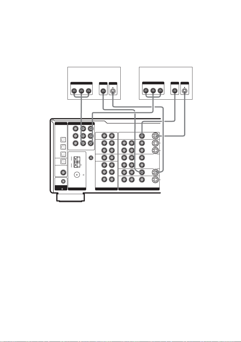
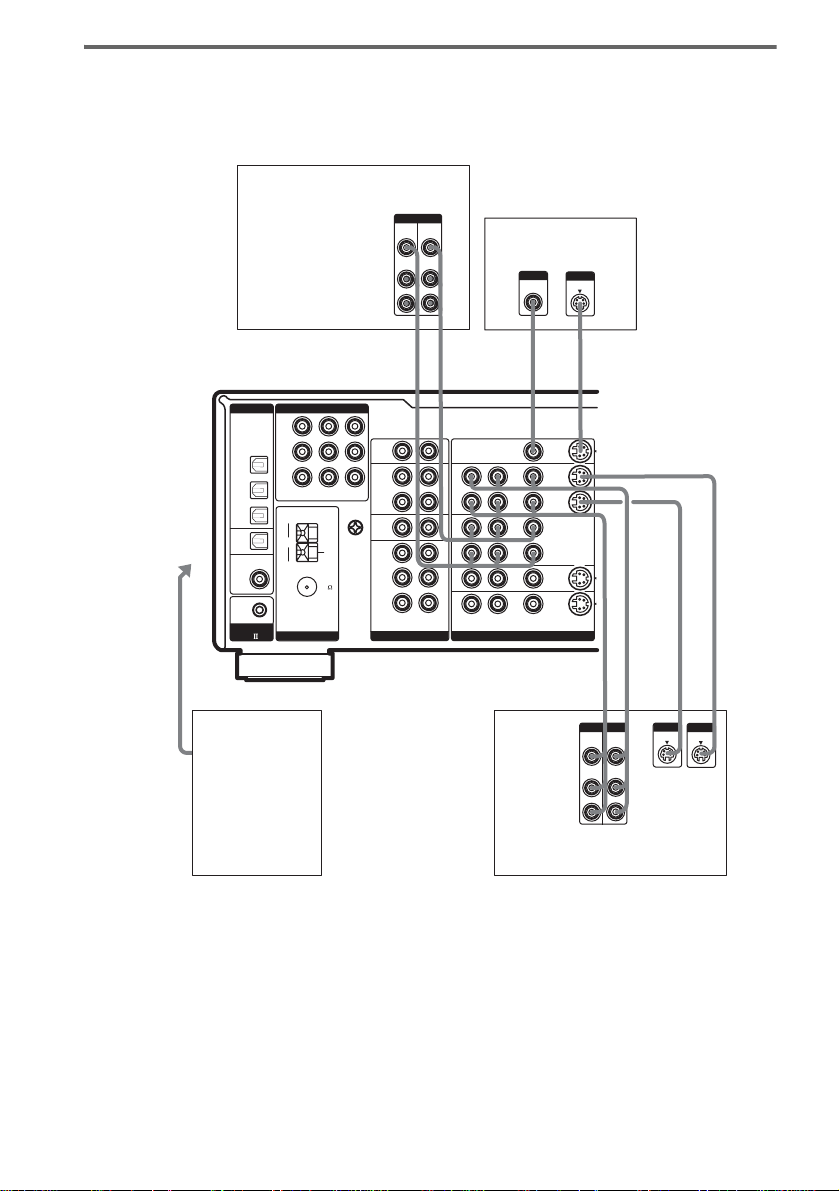
2 Connect the video jacks.
The following illustration shows how to connect a TV or satellite tuner and a DVD player with
COMPONENT VIDEO (Y, B-Y, R-Y) output jacks. Connecting a TV with component video input
jacks allows you to enjoy higher quality video.
Note
On this receiver, the component video signals cannot be converted to S-vide o or st an da rd video signals (or vice
versa).
Getting Started
Satellite tuner
OUTPUT
COMPONENT
B-Y
Y
R-Y
DIGITAL COMPONENT VIDEO
Y
OPTICAL
PB/C
B
/B-Y
DVD
IN
P
R/CR
/R-Y
TV/
SAT
IN
MD
IN
MD
OUT
COAXIAL IN
ASSIGNABLE
DVD
CD/SACD
CONTROL
A1
TV/SAT
AM
COAXIAL
FM
ANTENNA
DVD
IN
IN
U
75
OUTPUT
OUTPUT
VIDEO
S VIDEO
IN
PHONO
IN
MD/
MONITOR
TAPE
OUT
OUT
IN
CD/
SACD
U
SIGNAL
FRONT
GND
SURR
SUB WOOFER
MULTI CH IN
ANALOG VIDEO
OUTPUT
COMPONENT
B-Y
Y
R-Y
LR
LR
LR
LR
LR
CENTER
DVD player
INPUT
COMPONENT
B-Y
R-Y
HCDCDH
OUTMONITOR
I N
VIDEO
1
OUT
IN
VIDEO
2
OUT
IN
DVD
TV/
IN
SAT
LR
AUDIO VIDEO S-VIDEO
CDH
OUTPUT
OUTPUT
VIDEO
S VIDEO
TV monitor
Y
INPUT
VIDEO
INPUT
S VIDEO
continued
GB
9
Page 10
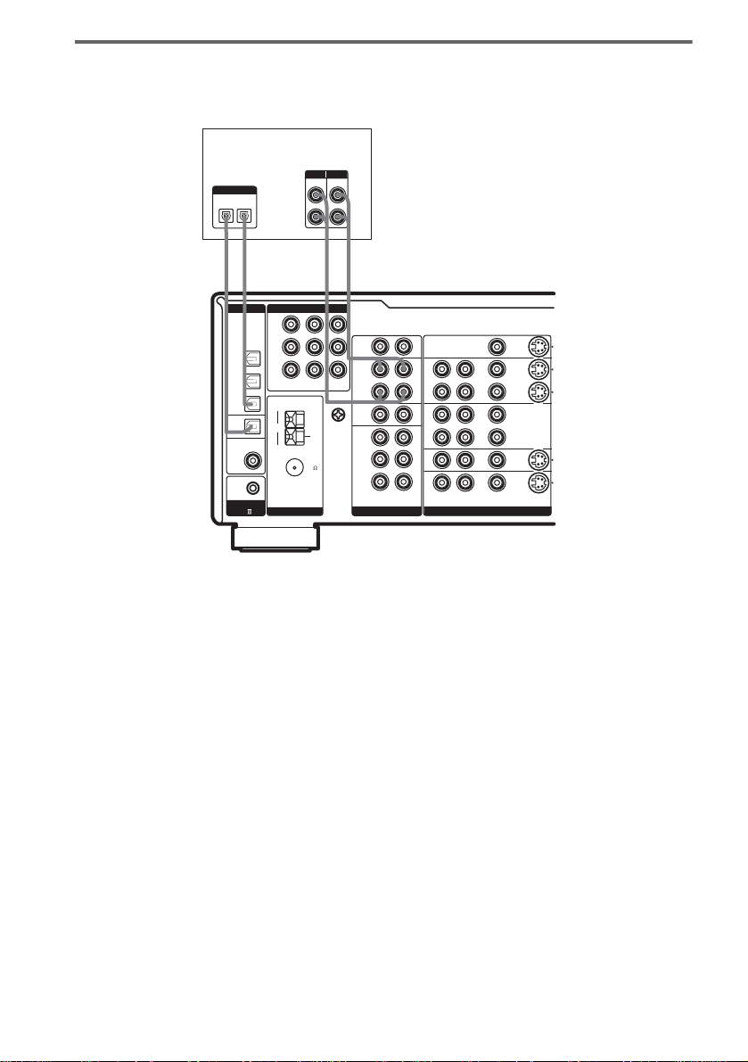
Hooking up an MD/Tape deck
For details on the required cords (A–H), see page 7.
MD/Tape deck
INPUT OUTPUT
LINE
INOUT
Y
PB/C
/B-Y
P
R/CR
/R-Y
AM
FM
B
TV/SAT
IN
COAXIAL
ANTENNA
LINE
L
R
l
INOUT
l
R
IN
PHONO
IN
MD/
TAPE
MONITOR
DVD
OUT
IN
OUT
IN
CD/
SACD
U
SIGNAL
FRONT
U
GND
SURR
75
SUB WOOFER
MULTI CH IN
ANALOG VIDEO
DIGITAL
OPTICAL
IN
OUT
EE A A
l
l
DIGITAL COMPONENT VIDEO
OPTICAL
DVD
IN
TV/
SAT
IN
MD
IN
MD
OUT
COAXIAL IN
ASSIGNABLE
DVD
CD/SACD
CONTROL
A1
CENTER
L
LR
LR
LR
LR
OUTMONITOR
I N
VIDEO
1
OUT
IN
VIDEO
2
OUT
IN
DVD
TV/
IN
SAT
LR
AUDIO VIDEO S-VIDEO
10
Tip
All the digital audio jacks are compa tible with 32 kHz, 44.1 kHz, 48 kHz and 96 kHz sampling frequencies.
Note
You cannot make digital recordings of digital multi channel surround signals.
GB
Page 11
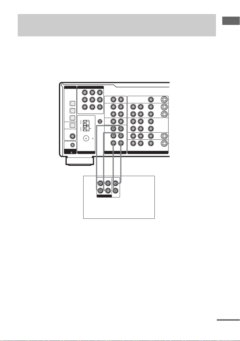
1b: Connecting components with multi channel output jacks
1 Connect the audio jacks.
If your DVD or Super Audio CD player is equipped with mult i channel output jacks, you can connect
it to this receiver’s MULTI CH IN jacks to enjoy the multi channel sound. Alternatively, the multi
channel input jac ks can be used to connect an external mul ti channel decoder.
For detail s on the req uired cords (A
DIGITAL COMPONENT VIDEO
OPTICAL
DVD
IN
TV/
SAT
IN
MD
IN
MD
OUT
COAXIAL IN
ASSIGNABLE
DVD
CD/SACD
CONTROL
A1
–H), see page 7.
Y
PB/C
B
/B-Y
P
R/CR
/R-Y
DVD
TV/SAT
IN
IN
AM
U
COAXIAL
FM
75
ANTENNA
LR
LR
IN
PHONO
IN
MONITOR
OUT
U
SIGNAL
GND
MD/
TAPE
CD/
SACD
FRONT
SURR
MULTI CH IN
LR
OUT
IN
LR
LR
CENTER
SUB WOOFER
ANALOG VIDEO
AUDIO VIDEO S-VIDEO
AA G G
FRONT
SURROUND
MULTI CH OUT
CENTER
SUB
WOOFER
L
R
DVD player,
Super Audio CD player,
Multi channel decoder, etc.
OUTMONITOR
I N
VIDEO
1
OUT
IN
VIDEO
2
OUT
IN
DVD
TV/
IN
SAT
LR
Getting Started
Tip
This connection also allows you to enjoy software with multi-channel audio recorded in formats other than the Dolby
Digital, and DTS.
continued
11
GB
Page 12
2 Connect the video jacks.
The following illustration shows how t o connect a DVD player with COMPONENT VIDEO (Y, B-Y,
R-Y) output jacks. Conn ect i ng a TV with component vi deo input jacks allows you t o enjoy higher
quality video.
Note
On this receiver, the component vi de o sign al s cannot be converted to S-video or standard vide o si gna ls ( or vic e
versa).
DVD player
OUTPUT
COMPONENT
B-Y
R-Y
DIGITAL COMPONENT VIDEO
Y
OPTICAL
PB/C
B
/B-Y
DVD
IN
P
R/CR
/R-Y
TV/
SAT
IN
MD
IN
MD
OUT
COAXIAL IN
ASSIGNABLE
DVD
CD/SACD
CONTROL
A1
TV/SAT
AM
COAXIAL
FM
ANTENNA
DVD
IN
IN
U
75
OUTPUT
OUTPUT
VIDEO
Y
MONITOR
OUT
U
SIGNAL
GND
S VIDEO
IN
PHONO
IN
MD/
TAPE
OUT
IN
CD/
SACD
FRONT
SURR
CENTER
SUB WOOFER
MULTI CH IN
ANALOG VIDEO
LR
LR
LR
LR
LR
LR
AUDIO VIDEO S-VIDEO
TV monitor
R-Y
INPUT
COMPONENT
B-Y
INPUT
INPUT
VIDEO
Y
S VIDEO
HCDCDH
OUTMONITOR
I N
VIDEO
1
OUT
IN
VIDEO
2
OUT
IN
DVD
TV/
IN
SAT
12
GB
Page 13
1c: Connecting components with only analog audio jacks
Hooking up audio components
For detail s on the req uired cords (A–H), see pa ge 7.
Turntable
A
DIGITAL COMPONENT VIDEO
Y
OPTICAL
DVD
IN
TV/
SAT
IN
MD
IN
MD
OUT
COAXIAL IN
ASSIGNABLE
DVD
CD/SACD
CONTROL
A1
PB/C
/B-Y
P
R/CR
/R-Y
AM
FM
B
TV/SAT
IN
COAXIAL
ANTENNA
PHONO
MD/
MONITOR
DVD
TAPE
OUT
IN
CD/
SACD
U
SIGNAL
FRONT
U
GND
SURR
75
MULTI CH IN
A
OUTPUT
LR
LR
IN
IN
LR
OUT
IN
LR
LR
CENTER
SUB WOOFER
ANALOG VIDEO
AUDIO VIDEO S-VIDEO
l
INPUT OUTPUT
LINE
L
R
LINE
OUTMONITOR
IN
VIDEO
1
OUT
IN
VIDEO
2
OUT
IN
DVD
TV/
IN
SAT
LR
INOUT
l
AA
LINE
L
R
Getting Started
CD/Super Audio CD
player
MD/Tape deck
Note
If your turntable has a ground wire, connect it to the U SIGNAL GND terminal.
continued
13
GB
Page 14
Hooking up video components
If you connect your T V to the MONITOR jack s, you can watch the vide o f rom the selected input
(page 24). For details on the requir ed cords (A
VCR
DIGITAL COMPONENT VIDEO
Y
OPTICAL
PB/C
B
/B-Y
DVD
IN
P
R/CR
/R-Y
TV/
To the
VIDEO 3
INPUT jacks
ASSIGNABLE
DVD
CD/SACD
B, D
Camcorder or
TV game
SAT
IN
MD
IN
MD
OUT
COAXIAL IN
CONTROL
A1
TV/SAT
AM
COAXIAL
FM
ANTENNA
MONITOR
DVD
IN
IN
SIGNAL
U
75
–H), see page 7.
OUTPUTINPUT
VIDEO
VIDEO
OUT
IN
AUDIO
AUDIO
OUT
IN
L
R
B BDC
L
L
LR
IN
PHONO
IN
MD/
TAPE
OUT
OUT
CD/
SACD
U
FRONT
GND
SURR
MULTI CH IN
LR
IN
LR
LR
CENTER
SUB WOOFER
ANALOG VIDEO
TV monitor
INPUT
VIDEO
INOUT
OUTMONITOR
IN
VIDEO
OUT
IN
VIDEO
OUT
IN
DVD
TV/
IN
SAT
LR
AUDIO VIDEO S-VIDEO
INPUT
S VIDEO
1
2
L
BB DD
OUTPUTINPUT
VIDEO
VIDEO
OUT
IN
AUDIO
AUDIO
OUT
IN
L
R
VCR
OUT
L
L
R
L
L
INOUT
INPUT
OUTPUT
S VIDEO
S VIDEO
IN
14
GB
Page 15
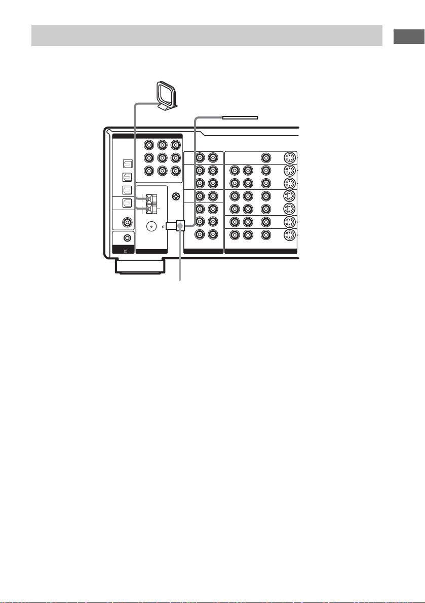
2: Connecting the antennas
Connect the supplied AM loop antenna and FM wire antenna.
AM loop antenna
(supplied)
FM wire antenna
(supplied)
DIGITAL COMPONENT VIDEO
Y
OPTICAL
PB/C
B
DVD
IN
TV/
SAT
IN
MD
IN
MD
OUT
COAXIAL IN
ASSIGNABLE
DVD
CD/SACD
CONTROL
A1
/B-Y
P
R/CR
/R-Y
AM
FM
ANTENNA
TV/SAT
IN
COAXIAL
PHONO
MD/
MONITOR
DVD
TAPE
OUT
IN
OUT
CD/
SACD
U
SIGNAL
FRONT
U
GND
SURR
75
MULTI CH IN
*
*
The shape of the connector varies depend ing on the area code.
Notes
• To prevent noise pickup, keep the AM loop antenna away from the receiver and other components.
• Be sure to fully extend the FM wire an ten n a.
• After connecting the FM wire ante nna, keep it as horizontal as possible.
• Do not use the U SIGNAL GND terminal for grounding the receiver.
L
R
LR
IN
IN
LR
IN
LR
LR
CENTER
SUB WOOFER
ANALOG VIDEO
AUDIO VIDEO S-VIDEO
OUTMONITOR
I N
VIDEO
1
OUT
IN
VIDEO
2
OUT
IN
DVD
TV/
IN
SAT
LR
Getting Started
15
GB
Page 16
3: Connecting speakers
Connect your speakers to the receiver. This receiver allows you to use a 7.1 channel system (STRDA1000ES) or 6.1 channel speake r system (STR-D B790).
To fully enjoy theater-like multi channel surround sound requires five sp eake rs (two front speakers, a
center speake r, and two surround speakers) and a sub w oofer (5.1 channel ).
You can enjoy high fidelity reproduction of DVD software recorded in the Surround EX format if you
connect one addit ional surround bac k s p eaker (6.1 channel ) or t w o surround back speakers (7.1
channel, STR-DA1000ES only) (see “Selecting the surr ound back decodin g m ode” on page 34) .
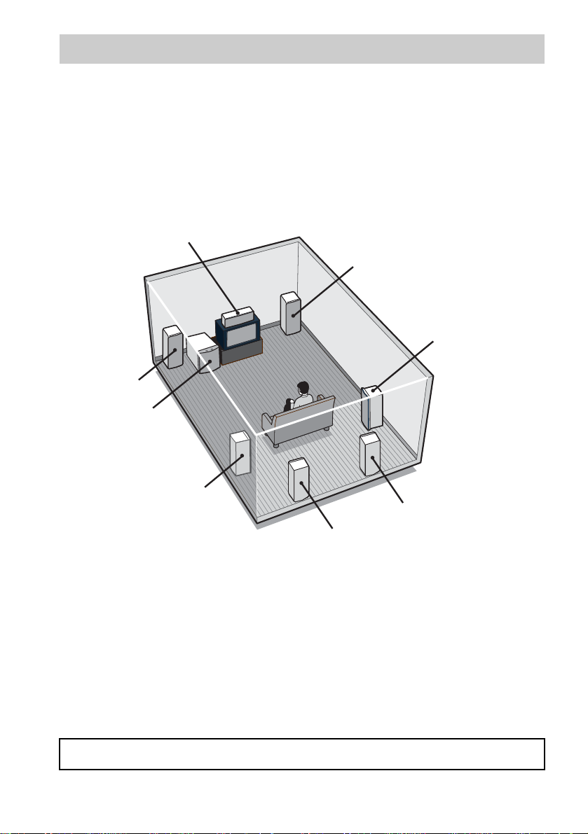
Example of 7.1 channel speaker system configuration
Center speaker
Front speaker (R)
Surround speaker (R)
Front speaker (L)
Sub woofer
16
Surround speaker (L)
Surround back speaker (R)
Surround back speaker (L)
Tips
• When you connect 6.1 channel speaker system, place the surround back speaker right behind the listening position.
• Since the sub woofer does not emit highly directional signals, you can place it wherever you want.
Speaker impedance
To enjoy the best possible multi channel surround, connect speakers with a nominal impedance of 8
ohms or higher to the FRONT, CENTER, SURROUND and SURROUND BACK terminals, and set
the IMPEDANCE SELECTOR to “8Ω”. Refer to the operating instructions supplied with your
speakers if you are not sure of their impedance. (This information is often on the back of the speaker.)
Alternatively, you may connect speakers with nominal imped ances betwee n 4 and 8 ohms to any or all
of the speaker terminals. However, be sure to set the IMPEDANCE SELECTOR to “4Ω” if you
connect even one speaker with a nominal impedance between 4 and 8 ohms.
Note
Be sure to turn the power off before adjusting the IMPEDANCE SELECTOR.
GB
Page 17
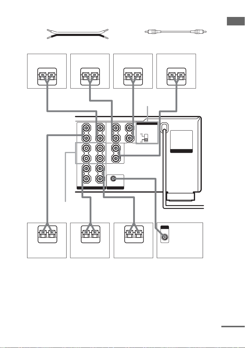
Required cords
A Speaker cords (not supplied)
(+)
(–)
STR-DA1000ES
B Monaural audio cord (not supplied)
Black
Getting Started
Surround speaker
(L)
Surround back
speaker (R)
EeAEe
+
SURR
–
+
FRONT
B
–
+
FRONT
A
–
SPEAKERS
FRONT B**
A
E
e
E
*
Surround back
speaker (L)
*
Ee
AA
Center speaker
Ee
A
IMPEDANCE
SELECTOR
+
–
+
–
LR
A
IMPEDANCE SELECTOR
4
8
B
e
INPUT
AUDIO
IN
AC OUTLET
LR
SURR
BACK
LR
CENTER
LR
SUB WOOFERSPEAKERS
eAE
Surround speaker
(R)
Front speaker (R)
Front speaker (L)
Sub woofer
* You can select the front speake rs you want to us e with SPEAKERS. F or details , see “Select ing the speak er system”
(page 43).
**If you connect only one surround back speake r, co nne ct it to the S PEAKERS SURR BACK L terminal.
continued
17
GB
Page 18

STR-DB790
Surround speaker
(L)
Surround back
speaker
Center speaker
EeAEe
+
SURR
–
+
FRONT
B
–
+
FRONT
A
–
SPEAKERS
FRONT B*
A
E
eAE
LR
LR
SURROUND BACK
SUB WOOFERSPEAKERS
e
E
Ee
AA
IMPEDANCE
SELECTOR
IMPEDANCE SELECTOR
LR
+
–
CENTER
A
e
B
INPUT
AUDIO
IN
AC OUTLET
18
Surround speaker
(R)
Front speaker (R)
Front speaker (L)
Sub woofer
* You can select th e front speak ers you want to use with SPEAKERS. For details , see “Sele cting the spea ker system”
(page 43).
GB
Page 19

4: Connecting the AC power cord
Connect the AC power cord to a wall outlet.
AC OUTLET
AC OUTLET
*
1 Press ?/1 to turn off the receiver.
2 Hold down ?/1 for 5 seconds.
“INITIAL” appe ars in the display.
The following are reset to their factory
settings.
• All settings in the SP SETUP, LEVEL,
EQ, CUSTOMIZE and TUNER menus.
• The sound field memor ized for each
input and pres et station.
• All preset stations.
• All index names for inputs and preset
stations.
Getting Started
AC power
cord
* Models of area code U, CA, SP only.
The configuration, shape, and number of AC outlets
vary according to the model and the ar ea co d e.
Notes
• The AC OUTLET(s) on the rear of the receiver is a
switched outlet, which supplies power to the
connected component only while the receiver is
turned on.
• Make sure that the total power consumption of the
component(s) connected to the receiver’s AC
OUTLET(s) does not exceed the wattage stated on
the rear panel. Do not connect high-wattage
electrical home appliances such as electric irons,
fans, or TVs to this outlet. Th is may cause a
malfunction.
To a wall outlet
b
Performing initial setup
operations
Before using the receiver for the first time,
initialize the receiver by performing the
following procedure.
This procedure can a ls o be used to return
settings you have made to their factory defaul t s.
19
GB
Page 20

5: Setting up the speakers
You can use the SP SETUP menu to set the size
and distance of th e speakers conne ct ed to this
system.
1 Press ?/1 to turn on the system.
2 Press MAIN MENU repeatedly to select
“SP SETUP”.
3 Rotate MENU to select the menu item
you want.
For more informat i on, see “Speaker setup
parameters”.
Note
Some speaker setup items may appear dimmed in
the display. This means that they ha ve been
adjusted automatically due to other speaker
settings. Depending on the setti ngs, you ma y or
may not be able to adjus t ce r tain speakers.
4 Rotate –/+ to select the parameter.
5 Repeat steps 3 and 4 until you have set
all of the items that follow.
Speaker setup parameters
The initial settings are underlined.
x XXXX SET (Speaker easy setup)
• EASY SET
You can set up your speakers autom a t i cal ly
by selecting a pre-defined sp eaker pattern (s ee
the supplied “Eas y Se tup Guide”).
• NORM. SET
Select to adjust the settings of each s peaker
manually.
x SP PAT. XXX (Speaker setup pattern)
When you selec t E ASY SE T, sel ect th e sp eak er
setup pattern. Rotate –/+
setup pattern and press MEMORY/ENTER to
enter the selecti on. Check your speake r pattern
using the supplied “Easy Setup Guide”.
SW
x (SUB WOOFER) (Sub woofer)
•YES
If you connect a sub woofer, select “Y ES” .
•NO
If you did not connect a sub woofer, select
“NO”. The front speakers are automatically
to select the speaker
set to “LARGE”. This activates the bass
redirection circuitry and outputs the LFE
signals from other speakers.
L
R
x (FRONT) (Front speakers)
• LARGE
If you connect large speakers that will
effective ly re produc e bass freq uen cies, select
“LARGE”. Normally, select “LARGE”.
•SMALL
If the sound is distorted, or you feel a lack of
surround effects when using multi channel
surround sound, select “SMALL” to act ivate
the bass redirect i on circuitry and outp ut the
front channel ba ss frequencies from the sub
woofer. When the front speakers are set to
“SMALL”, the center, surround and surround
back speakers are also automati cal l y set to
“SMALL” (unless previously set to “NO”).
C
x (CENTER) (Center speaker)
• LARGE
If you connect a large speaker that will
effective ly re produc e bass freq uen cies, select
“LARGE”. Normally, select “LARGE”.
However, if the fr ont speakers are set to
“SMALL”, you cannot set the center speaker
to “LARGE”.
•SMALL
If the sound is distorted, or you feel a lack of
surround effects when using multi channel
surround sound, select “SMALL” to act ivate
the bass redirect i on circuitry and outp ut the
center channel bass frequencies from the front
speakers (if set to “LARGE”) or sub w oofer.
• NO or MIX
If you did not connect a center speaker, select
“NO” or “MIX”. The sound of the ce nt er
channel will be output from the fron t
speakers.
When you select “MIX”, the sound of the
center channel will be output from the front
speakers thro ugh analog processi ng (analog
downmix) if the fr ont speakers are se t to
“LARGE”. This reproduces better sound than
digital processing. When the multi channel
input is selected, analog downmixing is
performed whether the setting is “NO” or
“MIX”.
20
GB
Page 21

SR
SL
x (SURROUND)
(Surround speakers)
• LARGE
If you connect large speakers that will
effectively reproduce bass frequencies, select
“LARGE”. Normally, select “LARG E”.
However, if the front speakers are set to
“SMALL”, you cannot set the surround
speakers to “LARGE”.
•SMALL
If the sound is distorted, or you feel a lack of
surround effects when using multi c hannel
surround sound, select “SMALL” to activat e
the bass redire ction circuitry and out put the
surround chan nel bass frequenci es from the
sub woofer or ot her “LARGE” speak er s.
•NO
If you did not connect surround speakers,
select “NO”.
SB
x (SURR BACK)
(Surround back speakers)
STR-DA1000ES
• DUAL
If you connect tw o surround back speakers,
select “DUAL”. The sound will be output to a
maximum of 7.1 channels.
•SINGLE
If you connect only one surround back
speaker, select “SINGLE”. The sound will be
output to a maximum of 6.1 channels.
•NO
If you did not connect surround back
speakers, select “NO”.
STR-DB790
•YES
If you connect a su rround back spea ker, select
“YES”.
•NO
If you did not connect surround back speaker,
select “NO”.
Tip
The “LARGE” and “SMALL” settings for each
speaker determine whether or not the int erna l sound
processor will cut the bass signal from that channel.
When the bass is cut from a cha nnel, the bass
redirection circuitry sends the corres pondi ng ba ss
frequencies to the sub woofer or other “LARGE”
speakers.
However, it best not to cut them, if poss ible. Therefore,
even when using small speakers, you c an set them to
“LARGE” if you want to output the bass frequencies
from that speaker. On the other hand, if you are using
a large speaker, but prefer not to have bass frequencies
output from that spea k e r, se t it to “SMALL”.
If the overall sound level is lower than you prefer, set
all speakers to “LARGE”. If there is not enough bass,
you can use the equalizer to boost th e bass levels. To
adjust the equalizer, see page 38.
L
R
x DIST. X.X m
(Front speaker distance)
Initial setting: 3.0 m (10 ft)
Lets you set the distance from your listening position
to the front speakers (A). You can adjust from 1.0
meter to 7.0 meters (3 to 23 feet) in 0. 1 meter (1 foot)
steps.
If both front speakers are n ot p lac ed an eq ua l d i st an ce
from your listening position, set the distance to the
closest speaker.
When placing only one surround bac k spe a ke r
A A
30˚30˚
100˚-120˚100˚-120˚
When placing two surround back spea ke rs
(The angle B should be the same)
AA
30˚30˚
100˚-120˚100˚-120˚
B
B
B
C
x DIST. X.X m
(Center speaker distance)
Initial setting: 3.0 m (10 ft)
continued
21
Getting Started
GB
Page 22

Lets you set the distance from your listening position
to the center speak er. You can adjust fro m 1.0 me ter to
7.0 meters (3 to 23 feet) in 0.1 meter (1 foot) steps.
SR
SL
x DIST. X.X m
(Surround speaker distance)
Initial setting: 3.0 m (10 ft)
Lets you set the distance from your listening position
to the surround speakers. You can adjust from 1.0
meter to 7.0 meters (3 to 23 feet) in 0.1 meter (1 foot)
steps.
If both surround speakers are not placed an equal
distance from your listening position, set the distance
to the closest speaker.
SB
x DIST. X.X m
(Surround back speaker distance)
Initial setting: 3.0 m (10 ft)
Lets you set the distance from your listening position
to the surround back speaker. You can adju st from 1.0
meter to 7.0 meters (3 to 23 feet) in 0.1 meter (1 foot)
steps.
If you connect two surround back speakers and both
surround back speakers are not place d an equa l
distance from your listening position (STRDA1000ES only), set the distance to the c lose st
speaker.
Tip
The receiver lets you to input the speaker position in
terms of distance. However, it is not possible to set the
center speaker further than the front speak ers. Also, the
center speaker cannot be set more that 1.5 meters (5
feet) closer than the front speakers.
Likewise, the surround speakers can not be set far the r
away from the listen ing position than the front
speakers. And they can be no more than 4.5 meters (15
feet) closer.
This is because incorrect speaker placement is not
conducive to the enjoyment of surround sound.
Please note that, setting the speaker distance closer than
the actual location of the speakers will cause a delay in
the output of the sound from that speaker. In other
words, the speaker will sound like it is farther away.
For example, setting the cent e r speaker distance 1–2
meters (3–6 feet) closer than the actual speaker
position will create a fairly realistic sensation of being
“inside” the screen. If yo u cannot obtain a sa tis facto ry
surround effect because the surround speakers are too
close, setting the surround speake r distance closer
(shorter) than the actual distance will create a larger
sound stage.
Adjusting these parameter while listening to the sound
often results in much better surr ound sound. Give it a
try!
For advanced speaker setups
Use the CUSTOMIZE menu and set “MENU”
to “MENU EXP.”. This enables advanced setups
including those o f th e heights of the surr ound
speakers.
For details on “MENU”, see page 38. For details
on how to set the items, see page 39.
22
GB
Page 23

6: Adjusting the speaker levels and balance
— TEST TONE
Adjust the speaker levels and balance while
listening the test tone from your listening
position. Use the remote for the operation.
Tip
The receiver employs a test tone with a frequency
centered at 800 Hz.
1 Press ?/1 on the remote to turn on the
receiver.
2 Press TEST TONE on the remote.
“T.TONE” appear s i n th e di splay and the
test tone is output from each speaker in
sequence.
3 Adjust the speaker level and balance
using the LEVEL menu so that the level
of the test tone sounds the same from
each speaker.
For details on the LEVEL menu settings,
see page 36.
Tips
• To adjust the level of all spea ke r s a t the same
time, press MASTER VOL +/– on the remote or
turn MASTER VO L U ME –/+ on the receiver.
• You can also use –/+ on the receiver for the
adjustment.
4 Press TEST TONE again after
adjustment.
The test tone turns off.
To output the test tone only from
a specific speaker
Set “T.TONE” in the LEVEL menu to “FIX”
(page 36). The test tone is output only from the
selected speaker.
For more precise adjustment
You can output the test tone or sound source
from two adjacent speakers to adjus t t heir
balance and level.
Set “MENU” in the CUSTOMIZE menu to
“MENU EXP.” (page 38). Then select the two
speakers you want to adjust using “P.NOISE” or
“P.AUDIO” in the LEVEL menu (page 41).
Note
The test tone cannot be used when ANALOG DIRECT
or MULTI CH IN function is used.
Getting Started
23
GB
Page 24

Amplifier Operation
Selecting the component
1 Rotate INPUT SELECTOR to select the
input.
The selected inpu t appears in the displ ay.
To select the Display
VCR VIDEO 1 or
Camcorder or TV game VIDEO 3
DVD player DVD
Satellite tuner TV/SAT
MD or tape deck MD/TAPE
CD or Super Audio CD
player
Built-in tuner (FM ) Tuner (FM)
Built-in tuner (AM) Tuner (AM)
Turntable PHONO
VIDEO 2
CD/SACD
2 Turn on the component and start
playback.
3 Rotate MASTER VOLUME –/+ to adjust
the volume.
To mute the sound
Press MUTING on the remote.
Notes on using headphones
• When headphones are connected, you can select only
the following sound fields (page 33).
– HEADPHONE (2CH)
– HEADPHONE THEATER
• When headphones are connected and you use the
MULTI CH IN functi o n (see “Listening to multi
channel sound”), the sound of all channels may not
output de pending on the s peaker settin gs.
Listening to multi channel sound
— MULTI CH IN
You can select the audio directly from the
components connected to the MULTI C H IN
jacks. This enables you to enjoy high quality
analog inputs like DVD or Super Audio CD.
Also see “D.PWR.” (page 39).
Surround effects ar e not activated when usi ng
this input.
STR-DA1000ES
Move the easy scroll key on the remote to
select “MULTI CH”, then press the key to
enter the selection.
STR-DB790
Press MULTI CH on the remote.
When a center speaker or sub
woofer is not connected
If you have set the center speaker to “N O ” or
“MIX”, or set the sub woofer to “NO” in the SP
SETUP menu (page 20), and you activate the
MULTI CH IN funct io n, the analog center or
sub woofer audio wil l b e output from the front
left and right speakers.
24
GB
Page 25

Listening to FM/AM radio
You can listen to FM and AM broadcasts
through the built -i n tuner. Before ope ration,
make sure you have connected the FM and AM
antennas to the receiver (see page 15).
Tip
The tuning scale for direct tuning differs depending on
the model.
Model FM AM
STR-DA1000ES 100 kHz 10 kHz*
STR-DB790 50 kHz 9 kHz
* The AM tuning scale can be changed (see page 50).
Automatic tuning
1 Rotate INPUT SELECTOR to select FM
or AM.
2 Press TUNING + or TUNING –.
Press TUNING + to scan from low t o high;
press TUNING – to sc an from high to low.
The receiver stops scanning whenever a
station is received.
Direct tuning
Enter a frequency of the station directly by using
the numeric buttons on the remote.
For details on the supplied remote, refer to the
operating instructions supplied with the remote.
1 STR-DA1000E S:
Move the easy scroll key on the remote
to select “TUNER”, then press the key
repeatedly to select FM or AM.
STR-DB790:
Press TUNER on the remote repeatedly
to select FM or AM.
You can also use INPU T SELECTOR on
the receiver.
2 Press ALT, then press D.TUNING on
the remote.
3 Press the numeric buttons on the
remote to enter the frequency.
Example 1: FM 102. 50 M H z
bbbb
1 0 2 50
Example 2: AM 1,350 kHz
(You don’t have to enter the last “0” w hen
the tuning scale is set to 10 kHz.)
bbb
1 3 50
If you’ve tuned in an AM station, adjust the
direction of the AM loop antenna for
optimum reception.
If you cannot tune in a station
and the entered numbers flash
Make sure you’ve entered the right frequency. If
not, repeat step 3. If the entered numbers still
flash, the frequency is not used in your area.
Amplifier Operation
25
GB
Page 26

Storing FM stations
Presetting radio stations
automatically
— AUTOBETICAL
(Models of area code CEL, CEK only)
This function lets you store up to 30 FM and FM
RDS stations in alphabetical order with out
redundancy. Add i ti onally, it only stores the
stations with the clearest signals.
If you want to store FM or AM s ta tions one by
one, see “Presetting radio stations”.
1 Press ?/1 to turn off the receiver.
2 Hold down MEMORY/ENTER and press
?/1 to turn the receiver back on.
“AUTO-BETICAL SELECT” appears in
the display and the receiver scans and stores
all the FM and FM RDS stations in the
broadcast area.
For RDS stations, the tuner first checks for
stations broadcasting the same program,
then stores only the one with the clearest
signal. The s electe d RDS stat ions are s orted
alphabeticall y by their Program Service
name, then assigned a 2-character preset
code. For more det ails on RDS, see
page 27.
Regular FM stations are assigned 2character preset codes and stored after the
RDS station.
When done, “FINISH” appears in the
display momentarily and the receiver
returns to the normal operation.
Notes
• Do not press any button on the recei ve r or supp lie d
remote during autobetica l ope ration, except ?/1.
• If you move to another area, repeat this procedure to
store stations in your new area.
• For details on tuning the stored stations, see “Tuning
to preset stations”.
• If you move the antenna after stori ng stations with
this procedure, the stored settings may no longer be
valid. If this happens, repeat this procedure to store
the stations again.
You can preset up to 30 FM or AM stations.
Then you can easily t une in the stations you
often listen to.
Presetting radio stations
1 Rotate INPUT SELECTOR to select FM
or AM.
2 Tune in the station that you want to
preset using Automatic Tuning
(page 25) or Direct Tuning (page 25).
3 Press MEMORY /ENTE R.
“MEMORY” appe ars in the display for a
few seconds. Do steps 4 to 5 befo re the
display goes out.
4 Press PRESET TUNING + or PRESET
TUNING – to select a preset number.
If you want to switch the memory page,
press SHIFT on the remote.
If “MEMORY” goes out before you select
the preset numbe r, st ar t again from step 3.
5 Press MEMORY /ENTE R again.
The station is stored to the selected preset
number.
If “MEMORY” goes out before you press
MEMORY/ENTER, start again from step
3.
6 Repeat steps 2 to 5 to preset another
station.
Tuning to preset stations
1 Rotate INPUT SELECTOR to select FM
or AM.
2 Press PRESET TUNING + or PRESET
TUNING – repeatedly to select the
preset station you want.
Each time you press t he button, you can
select the preset st ation as follows :
tA1yA2y...yA0yB1yB2y...yB0T
26
tC0y...yC2yC1T
GB
Page 27

Using the remote
1 STR-DA1000ES:
Move the easy scroll key to select “TUNER”,
then press the key repeatedly to select FM
.
or AM
STR-DB790:
Press TUNER repeatedly to select FM or
.
AM
2 Press D.SKIP/CH/PRESET +/– repeatedly
to select the preset station you want
To select the Preset station
directly
Press the numeric buttons on the remote.
The preset station of the selected number in the
current memory page is tuned in. Press SHIFT
on the remote to change the memory page.
.
Using the Radio Data System (RDS)
(Models of area code CEL, CEK only)
This receiver also allows you to use RDS (Radio
Data System), which enables radio stations to
send additional i nformation along wi t h th e
regular program signal. You can also display
RDS information.
Receiving RDS broadcasts
Simply select a station on the FM band
using direct tuning (page 25), automatic
tuning (page 25), or preset tuning
(page 26).
When you tune in a station that provides RDS
services, the RDS indicator lights up and the
program service name appears in the display.
Note
RDS may not work properly if the station you tuned to
is not transmitting the
signal strength is weak.
Displaying RDS information
While receiving an RDS station, press
DISPLAY.
Each time you press th e button, RDS
information on the display change s cyclically as
follows:
PS (Program Service name) or preset station
namea) t Frequencyb) t PTY (Program
Type) indication
indication
(in 24-hour sy st em ) t Sound field currently
applied t Volume level
a)
b)
c)
d)
Notes
• If there is an emergency announcem en t b y
d)
This information appears only when PS is received
or the preset statio n is indexed.
This information als o appears for non-RDS FM
stations.
Type of program being broadcast (see page 28).
Text messages sent by the RDS stat ion.
government authorities, “ALAR M” f la she s in the
display.
RDS signal properly or if the
c)
t RT (Radio Text)
t CT (Current Time) indi cation
Amplifier Operation
continued
27
GB
Page 28

• If a station does not provide a particula r RDS
service, “NO XX” (such as “NO CT”) a ppea rs i n th e
display.
• When a station broadcasts radi o te xt da ta, it is
displayed at the same rate at which it is sent from the
station. Any change in this rate is reflect ed in the
display rate of the data.
Description of program types
Program type
indication
NEWS News programs
AFFAIRS Topic a l progr ams that expand on
INFO Programs offering information on
SPORT Sports programs
EDUCATE Educational programs, such as
DRAMA Radio plays and serials
CULTURE Progra m s about national or
SCIENCE Programs abou t the na tur a l
VARIED Other types of programs such as
POP M Popular music programs
ROCK M Rock music programs
EASY M Easy List en ing
LIGHT M Instrumental, voc al, and ch or al
CLASSICS Performances of major orchestras ,
OTHER M Music that does not fit into any
WEATHER Weather information
FINANCE Stock market reports and trading,
CHILDREN Programs for children
SOCIAL Programs about people and the
RELIGION Programs of religious content
Description
current news
a wide spectrum of subjects,
including consumer affairs and
medical advice
“how-to” and advice programs
regional culture, such as language
and social concerns
sciences and technology
celebrity interviews, panel games,
and comedy
music
chamber music, opera, etc.
categories above, such as Rhythm
& Blues and Reggae
etc.
things that affect them
Program type
indication
PHONE IN Programs where members of the
TRAVEL Programs about travel. Not for
LEISURE Programs on recreational
JAZZ Jazz programs
COUNTRY Countr y music programs
NATION M Programs featuring the popular
OLDIES Programs featuring oldies music
FOLK M Folk music programs
DOCUMENT Investig at iv e feat u res
NONE Any programs not defined above
Description
public express their views by
phone or in a public forum
announcements that are located by
TP/TA.
activities such as gardening,
fishing, cooking, etc.
music of the country or region
28
GB
Page 29

Changing the display
Changing the information in
the display
You can check the sound field etc. by changing
the information in the display.
Press DISPLAY repeatedly.
Each time you press DISPLAY, the display will
change as follows.
Index name* t Input name t Sound field
name t Volume level
* Index name appears only when you have assigned
one to the input or preset station (page 42) . Inde x
name does not appear when only blank spaces have
been entered, or it is the same as the input name.
Amplifier Operation
29
GB
Page 30

About the indications in the display
2134
7
5 6
DTS-ES
D.RANGE
LCR
L F E
SLSWSB SR
DIGITAL;PRO LOGIC II
SP BSP ASLEEP
OPT
EX
COAX MULTI CH IN
;
NEO:6
EQ
STEREO MONO
RDS
MEMORY
DIRECT
qgqh
qs
A SLEEP: Lights up when sleep timer is
activated.
B SPA/SPB: Lights up in accordance with the
speaker system being used (A or B). Turns off
when speaker output is turned of f or w he n
headphones are connected.
C ; DIGITAL (EX): Lights up when the
receiver is decoding signals recorded in the
Dolby Digital format.
D ; PRO LOGIC (II): Lights up when the
receiver applies Pro Logic pro ce ssin g to 2
channel signals in order to output the cent e r
and surround channel signals. This indicator
also lights when the Pr o Logic II movie/ music
decoder is activated. Ho wever, this indicator
does not light if both the center and surround
speakers are set to “NO”.
E DTS (-ES): Lights up when DTS signals are
input.
F NEO:6: Lights up when DTS Neo:6 cinema/
music mode decodin g is ac ti vated.
G DIRECT: Lights up when the ANALOG
DIRECT function is activated.
H Tuner indicators: Lights up when using the
receiver to tune in radio stations, etc. See
pages 25–28 for tuner operations.
I EQ: Lights up when the e quali zer is acti vate d.
J D.RANGE: Lights up when dynamic range
compression is activated (page 41).
K MULTI CH IN: Lights up when adjusting the
multi channel sub woofer level.
L COAX: Lights up when the source signal is a
digital signal being input through the
COAXIAL terminal.
9
0qdqf qa
8
M OPT: Lights up when the source signal is a
digital signal being input th rough the
OPTICAL terminal.
N LFE: Lights up when the di sc being played
back contains the LFE (L ow Fre quency
Effect) channel and the LFE channel signal is
actually being reproduced.
O Playback channel indicators: The letters
(L, C, R, etc.) indicate the channels being
played back. The boxes around the letters vary
to show how the receiver do w n mixes the
source sound (based on the speakers settin gs).
L (Front Left), R (Front Right), C (Center
(monaural)) , SL (Surroun d L eft), SR
(Surround Right) , S (Surround (monaural
or the surround components obtained by
Pro Logic pr ocessing)) , SB (Sur round Back
(the surround back components obtained by
6.1 channel decodi ng))
Example:
Recording format (Front /Surround): 3/2
Output channel: Surround spea ke r s abs en t
Sound Field: A.F.D. AUTO
LCR
SLSWSR
P SW: Lights up when sub woofer sel ec ti on is
set to “YES” ( page 20). Wh ile this indicator
lights up, the receiver outputs the LFE signal
recorded on the disc or gene rates a low
frequency signal for output to the sub woofer.
This indicator does not l ight during the 2CH
STEREO mode.
30
GB
Page 31

Enjoying Surround Sound
Using only the front speakers
In this mode, the receiver outputs the sound
from the front L/R speakers only. There is no
sound from the sub woofer.
Listening to 2 channel stereo
sources (2CH STEREO)
Standard 2 channel stereo sources completely
bypass the sound field processing and multi
channel surround formats are downmixed to 2
channel.
Press 2CH.
“2CH ST.” appears in the display and the
receiver switches to the 2CH STEREO mode.
Note
No sound is output from the sub woofer in the 2CH
STEREO mode. To listen to the 2 channel stereo
sources using the front L/R speakers and a sub woofer,
set to the A.F.D. mode.
Listening to analog audio
(ANALOG DIRECT)
You can switch the audio of the selected input to
the two channel analog input. This function
enables you to enjoy high quality analog
sources. Also see “D.PWR.” on page 39.
When using this function, only the volume and
front speaker bal a nce can be adjusted .
1 Rotate INPUT SELECTOR to select the
input you want to listen to in analog
audio.
2 Press DIRECT on the remote.
“A.DIRECT” appears in the display and the
analog audio is output.
Notes
• This function is cancelled when you switch the sound
field (pages 31-33).
• When this function is used, test tone function cannot
be used.
Enjoying higher fidelity sound
— AUTO FORMAT DIRECT
The Auto Format Direct (A.F.D.) mode allows
you to select the decoding mode you want for
your audio soun d.
A.F.D. mode
(Display)
A.F.D. AUTO
(A.F.D. AUTO)
PRO LOGIC
(DOLBY PL)
PRO LOGIC II MOVIE
(PLII MOV)
PRO LOGIC II MUSIC
(PLII MUS)
Neo:6 Cinema
(NEO6 CIN)
Neo:6 Music
(NEO6 MUS)
Decoding the input audio
signal automatically
In this mode, the receiver automatically detects
the type of audio sig nal being input (Dolby
Digital, DTS, standard 2 channel stereo, etc.)
and performs the proper decoding i f ne cessary.
This mode presents the sound a s it was recorded/
encoded, without adding any surroun d ef fects.
However, if ther e ar e no low frequency signals
(Dolby Digital LFE, etc.) it will generate a low
frequency signal for output to the sub woofer.
Press A.F.D. repeatedly to select “A.F.D.
AUTO”.
The receiver automatically detects the type of
audio signal being input an d performs th e proper
decoding if necessary.
Tip
In most cases, “A.F.D. AUTO” provides the most
appropriate decoding. You may want to use SURR
BACK DECODING (page 34) to match the input
stream to the mode you prefer.
Decoding mode
As encoded
Dolby Pro Logic
Dolby Pro Logic II
DTS Neo:6
Enjoying Surround Sound
continued
31
GB
Page 32

Enjoying stereo sound in multi
channel (2 channel decoding
mode)
This mode lets you specify the type of decoding
for 2 channel audio sources. This receiver can
reproduce 2 channel sound in 5 channe ls
through Dolb y Pro Lo gi c I I; 6 ch an nel s t hro ug h
DTS Neo:6; or 4 channels through Dolby Pro
Logic. However, DTS 2CH sources are not
decoded by DTS Neo:6; they are output in 2
channels.
Press A.F.D. repeatedly to select the 2
channel decoding mode.
x PRO LOGIC
Performs Dolby Pro Logic decoding. The sourc e
recorded in 2 channel is decoded into 4.1 channels.
x PRO LOGIC II MOVIE
Performs Dolby Pro Logic II Movie mo de dec oding.
This setting is ideal f or mo vies encoded in Dolby
Surround. In Addition, this mode can reproduce sound
in 5.1 channel when watching videos of overdubbed or
old movies.
x PRO LOGIC II MUSIC
Performs the Dolby Pro Logic II Music mode
decoding. This setting is ide al for nor ma l stereo
sources such as CDs.
x Neo:6 Cinema
Performs the DTS Neo:6 Cinema mode decoding.
x Neo:6 Music
Performs the DTS Neo:6 Music mode decoding. T his
setting is ideal for normal stereo sources such as CDs.
If you connect a sub woofer
When the audio signal is 2 channel stereo or if
the source signal does not include a LFE signal,
the receiver generates a low frequency signal for
output to the sub woofer. However the low
frequency signal i s not generated when “Neo:6
Cinema” or “Neo:6 Music” is selected.
Selecting a sound field
You can take advant age of surround sound
simply by selecting one of the receiver’s preprogrammed so und fields. They bring t he
exciting and powerful sound of movie theaters
and concert halls in to your home.
Selecting a sound field for
movies
Press MOVIE repeatedly to select the
sound field you want.
The selected sound field appears in th e di splay.
Sound field Display
CINEMA STUDIO EX A DCS C.ST.EX A
CINEMA STUDIO EX B DCS C.ST.EX B
CINEMA STUDIO EX C DCS C.ST.EX C
VIRTUAL MULTI DIMENSION
DCS
About DCS (Digital Cinema
Sound)
Sound fields with DCS marks use DCS
technology.
DCS is the concept name of the surround
technology for home theater developed by Sony.
DCS uses the DSP (Digital Signal Proce ss o r )
technology to reproduce the sound
characteristics of an actual cinema cutting studio
in Hollywood.
When played at home, DCS will create a
powerful theat er effect that mimics the artistic
combination of sound and action as envisioned
by the movie director.
x C.ST.EX A (CINEMA STUDIO EX A) DCS
Reproduces the sound characterist ic s of the Sony
Pictures Entertainment “Cary Grant Theater” cinema
production studio. This is a standard mode, grea t fo r
watching most any type of movies.
x C.ST.EX B (CINEMA STUDIO EX B) DCS
Reproduces the sound characterist ic s of the Sony
Pictures Entertainment “Kim Novak The ater” cinema
production studio. This mode is ideal for wat ch ing
science-fiction or action mo vie s with lots of sound
effects.
V.M.DIM
32
GB
Page 33

x C.ST.EX C (CINEMA STUDIO EX C) DCS
Reproduces the sound characte ristics of the Sony
Pictures Entertainment scoring stage. This mode is
ideal for watching musica ls or films where orchestra
music is featured in the soundtrack.
x V.M.DIM (VIRTUAL MULTI DIMENSION)
DCS
Creates 5 sets of virtual speakers from a single pair of
actual surround speakers.
About CINEMA STUDIO EX modes
CINEMA STUDIO EX modes are suitable for
watching motion picture DVDs (etc.), with
multi channel surround effects. You can
reproduce the sound characteristi cs of Sony
Pictures Entertainment’ s dubbing studio in your
home.
The CINEMA STUDIO EX modes consist of
the following three elements.
• Virtual Multi Dimension
Creates 5 sets of virtual speakers from a single
pair of actual surround speakers.
• S creen Depth Matching
Creates the sensati on that th e sound is coming
from inside the s c reen like in theate rs.
• Cinema Studio Reverberat i on
Reproduces the type of reverberation found in
theaters.
The CINEMA STUDIO EX modes integrate
these three elem ents simultaneously.
Tip
You can identify the encoding format of DVD
software, etc. by looking at the logo on the package.
– : Dolby Digital discs
– : Dolby Surround encoded programs
– : DTS Dig ita l Surround encoded programs
Notes
• The effects provided by the virtual spea ke rs may
cause increased noise in the playback signal.
• When listening with sound fields that employ the
virtual speakers, you will not be able to hear any
sound coming directly from the sur r ound speakers.
Sound field Display
HALL HALL
JAZZ CLUB JAZZ
LIVE CONCERT CONCERT
x HALL
Reproduces the acoustics of a cla ssical concert hall.
x JAZZ (JAZZ CLUB)
Reproduces the acoustics of a jazz club.
dance club.
x CONCERT (LIVE CONCERT)
Reproduces the acoustics of a 300 -seat live house.
When the headphones are
connected
You can select only from the followi ng sound
fields.
x HEADPHONE (2CH)
Outputs the sound in 2 channel (stereo) . Standa r d 2
channel stereo sources compl et e ly bypa ss the sound
field processing and multi channe l surround formats
are downmixed to 2 channels.
x HEADPHONE THEATER DCS
Allows you to experience a theater-lik e environme n t
while listening through a pair of headphones.
Note
If you connect a pair of headphones while a sound field
is operating, the system will automatically switch to
HEADPHONE (2CH) if using a sound field selected
with the 2CH or A.F.D. button, or to HEADPHONE
THEATER if using a sound field selected with the
MOVIE or MUS I C button.
To turn off the surround effect
Press 2CH or A.F.D.
Note
Sound fields does not function for PCM 96 kHz
signals.
Enjoying Surround Sound
Selecting a sound field for
music
Press MUSIC repeatedly to select the
sound field you want.
The selected sound fie l d appears in the displ ay.
33
GB
Page 34

Selecting the surround back decoding mode
— SURR BACK DECODING
This function lets you select the decoding mode
for the surround back signals of th e multi
channel input stream.
By decoding the surround back signal of DVD
software (etc.) recorded in Dolby Digital EX,
DTS-ES Matrix, DTS-ES Discrete 6.1, etc.
format, you can en j o y t he surround sound
intended by the filmmakers.
Press SURR BACK DECODING repeatedly
to select the surround back decoding
mode.
For details, see “How to select the surround back
decoding mode” on page 35.
Tip
You can select the surround back decoding mode using
“SB XXXX” in the CUSTOMIZE menu (page 39).
Note
You can select the surround back decoding mode only
when A.F.D. mode is selected.
34
GB
Page 35

How to select the surround back decoding mode
You can select the surround back mode you want accord ing to the input stre am .
When you select “SB AUTO”
When the input strea m contains the 6.1 ch annel decode flaga), the appropriate decoder is appli ed to
decode the surround back signal.
Input stream Output channel Applied surround back decoder
Dolby Digital 5.1 5.1
Dolby Digital EX
b)
DTS 5.1 5.1
DTS-ES Matrix 6.1
DTS-ES Discrete 6.1
c)
d)
When you select “SB MTRX”
Dolby Digital EX is applied to decode the surround back signal regardless of the 6.1 channel decode
a)
in the input stream. This decoder conforms to Dolby Digital EX and functions the same as the
flag
f)
decoders
Input stream Output channel Applied surround back decoder
used in movie theaters.
Dolby Digital 5.1 6.1
Dolby Digital EX
b)
DTS 5.1 6.1
DTS-ES Matrix 6.1
DTS-ES Discrete 6.1
c)
d)
When you select “SB OFF”
Surround back decoding is not performed.
a)
6.1 channel decode flag is the information recorded in software like DVDs.
b)
Dolby Digital DVD that includes a Surround EX flag. The Dolby Corporation web page can help you distinguish
Surround EX films.
c)
Software encoded with a flag to denote it has both S ur round EX an d 5 .1 cha nne l signals.
d)
Software encoded with both 5.1 channe l signals and an extension stream desi gne d fo r retur ning those signals to
6.1 discrete channels. Discrete 6.1 channel signals are DVD specific signals not used in movie theaters.
e)
When two surround back speakers are connected, the output channel will be 7.1 channels (STR-DA1000ES only).
f)
This decoder can be used for all 6.1 formats (Dolby Digital EX, DTS-ES Matrix 6.1, DTS-ES Discrete 6.1 ).
Note
There may be no sound from the surround back speaker in Dolby Digital EX mode. Some discs have no Dolby Digital
EX flag even though the packages have Dolby Digital EX logos. In this case, select “SB MTRX”.
6.1
6.1
6.1
6.1
6.1
6.1
e)
e)
e)
e)
e)
e)
e)
e)
e)
e)
—
Matrix decoder confo rm s to Dolby Digital EX
—
DTS Matrix decoder
DTS Discrete decoder
Matrix decoder confo rm s to Dolby Digital EX
Matrix decoder confo rm s to Dolby Digital EX
Matrix decoder confo rm s to Dolby Digital EX
Matrix decoder confo rm s to Dolby Digital EX
Matrix decoder confo rm s to Dolby Digital EX
Enjoying Surround Sound
35
GB
Page 36

Advanced Adjustments and Settings
Switching the audio input mode for digital components
— INPUT MODE
You can switch th e audio input mode for
components whic h ha ve digital audio input
jacks.
1 Rotate INPUT SELECTOR to select the
input.
2 Press INPUT MODE repeatedly to
select the audio input mode.
The selected audi o in put mode appears in
the display.
Audio input modes
• AUTO IN
Gives priority to t he analog audio sign al s
input to the AUDIO IN (L/R) jacks when
there is no digital audio signals.
• COAX IN
Specifies the digital a udio si gnals input to the
DIGITAL COAXIAL input jack.
•OPT IN
Specifies the digital a udio si gnals input to the
DIGITAL OPTICAL input jacks.
• ANALOG
Specifies the analog audio signals input to the
AUDIO IN (L/R) jacks.
Customizing sound fields
By adjusting the LEVEL menu, you can
customize the sound fields to su it your particular
listening situa tio n.
Note on the displayed items
The setup items you can adjust in each me nu va ry
depending on the sound field. Certain setup parameters
may be dimmed in the displa y. This means that the
selected parameter is eith er una vailable or fixed and
unchangeable.
Adjusting the LEVEL menu
You can adjust the ba la nce and level of each
speaker. These set t ings are applied to all sound
fields.
1 Start playing a source encoded with
multi channel surround effects (DVD,
etc.).
2 Press MAIN MENU repeatedly to select
“LEVEL”.
3 Rotate MEN U to select the parameter.
For details, see “LEVEL menu parameters”
below.
4 While monitoring the sound, rotate –/+
to adjust the selected parameter.
5 Repeat steps 3 and 4 to adjust the other
parameters.
LEVEL menu parameters
x T.TONE (Test Tone)
Initial setting: OFF
Lets you output the test tone sequentia lly f r om e a ch
speaker. When set to “AUTO”, the test tone is output
from each speaker automatically. When set to “FIX”,
you can select which speaker will output the test tone.
x BAL. XXXX (Front speaker balance)
Initial setting: 0 (BAL A N CE)
Lets you adjust the balance between front left and right
speakers. You can adjust in the range of L (+1 to +16),
0, R (+1 to +16) in 33 steps.
36
GB
Page 37

x CTR XXX.X dB
(Center speaker level)
x SUR.L. XXX.X dB
(Surround speaker (L) level)
x SUR.R. XXX.X dB
(Surround speaker (R) level)
x SB XXX.X dB
(Surround back speaker level)*
x SBL XXX.X dB
(Surround back (L) level)**
x SBR XXX.X dB
(Surround back (R) level)**
x S.W. XXX dB
(Sub woofer level)
Initial setting: 0 dB
You can adjust from –20 dB to +10 dB in 0.5 dB steps.
MULTI CH IN
x SW. XXX dB
(Multi channel sub woofer level)
Initial setting: 0 dB
Lets you increase the level of the MULTI CH IN sub
woofer channel by +10 dB. This adjustment may be
necessary when connecting a DVD player to the
MULTI CH IN jacks. The sub woofer level from DVD
players is 10 dB lower than Super Audio CD pla ye r s.
* Only when the surround back speake r is set to
“SINGLE” (STR-DA1000ES) or “YES” (STRDB790) in the SP SETUP menu.
**Only when the sur r ound back speaker is set to
“DUAL” in the SP SETUP menu (STR-DA1000ES
only).
x EFCT. XXX (Effect level)
Initial setting: STD
Lets you adjust the size of the surround effect.
Note
When one of the following sound fields are selected,
no sound is output from the sub woofer if all the
speakers are set to “LARGE” in the SP SETUP menu.
However, the sound will be output from the sub woofer
if the digital input signal contains LFE (Low
Frequency Effect) signals, or if the fron t, center, or
surround speakers are set to “SMALL” .
– HALL
– JAZZ CLUB
– LIVE CONCERT
For advanced LEVEL menu
adjustments
Use the CUSTOMIZE menu and set “MENU”
to “MENU EXP.” to enabl e a dvanced
adjustments.
For details on “MENU”, see page 38. For details
on how to set the items, see page 41.
Resetting sound fields to the
initial settings
1 Press ?/1 to turn off the power .
2 While holding down MUSIC, press
?/1.
“S.F CLR.” appears in the display and all
sound fields are reset to the initial setting.
Advanced Adjustments and Settings
37
GB
Page 38

Adjusting the equalizer
Advanced settings
You can adjust th e t onal quality (bas s, tr eble
level) of each speaker using the EQ menu.
Bass Treble
Level
(dB)
Frequency
(Hz)
Frequency
(Hz)
1 Start playing a source encoded with
multi channel surround effects (DVD,
etc.).
2 Press MAIN MENU repeatedly to select
“EQ”.
3 Rotate MENU to select the parameter.
For details, see “EQ menu parameters”
below.
4 While monitoring the sound, rotate –/+
to adjust the selected parameter.
5 Repeat steps 3 and 4 to adjust the other
items.
Note
You cannot adjust the equalizer when the system is
decoding PCM 96 kHz signals, or when DTS 96/24 ,
DTS-ES Matrix or DTS Neo:6 decoding is applied.
EQ menu parameters
x EQ
Initial setting: OFF
Select “ON” to activate the equalizer.
L
R
x BASS XXX.X dB
(Front speaker bass level)
L
R
x
(Front speaker treble level)
Initial setting: 0 dB
You can adjust from –10 dB to +10 dB in 1 dB steps.
TREB. XXX.X dB
Using the CUSTOMIZE menu
to adjust the receiver
You can adjust va rious receiver settings using
the CUSTOMIZE menu.
1 Press MAIN MENU repeatedly to select
“CUSTOM”.
2 Rotate MEN U to select the parameter.
For details, see “CUSTOMIZE menu
parameters” below.
3 Rotate –/+ to adjust the selected
parameter.
4 Repeat steps 2 and 3 to adjust the other
items.
CUSTOMIZE menu parameters
The initial setting is underlined.
x MENU (Menu expanding)
• MENU EXP.
The advanced parameters for the SP S ETUP and
LEVEL menus are displayed and can be adjuste d.
For details on each setup item, see page s 20, 36 and
the following pag es .
• MENU STD
The advanced parameters are not displayed.
x 96 XXXX (DTS 96/24 decoding mode)
• 96 AUTO
When a DTS 96/24 signal is input, it is played back
at 96 kHz sampling frequencies.
• 96 OFF
Even when a DTS 96/24 signal is input, it is playe d
back at 48 kHz sampling frequencies.
Notes
• This parameter is valid only in the A.F.D. mode
(page 31). In other sound fields, this pa r am e te r is
always set to “96 OFF”.
• DTS 96/24 decoding is only valid in the A.F.D. mode
(page 31). When the system is set to oth er sound
fields, standard 48 kHz decoding is used.
• Even when a DTS 96/24 signal is input, standard 48
kHz decoding is used if any sp eak ers ar e se t to
“SMALL” or if the sub woofer is set to “NO” .
DTS
38
GB
Page 39

x SB XXXX
(Surround back decoding mode)
You can use the CUSTOMIZE menu to set the
surround back decoding mode (page 34).
For details on each decoding mode, see page 35.
• SB AUTO
•SB MTRX
•SB OFF
Note
This parameter is valid only in the A.F.D. mode
(page 31).
x S.F XXXX (Sound field link)
• S.F LINK
Lets you apply the last selected sound fiel d to an
input whenever it is selected. For examp l e, if you
select HALL for the CD/S ACD input, then change to
a different input and return to CD/SACD, HALL will
automatically be applied again.
• S.F FIX
Sound field link is not activated.
x DEC. XXXX
(Digital audio input decoding priority)
Lets you specify the input mode for the d igi ta l signal
input to the DIGITAL IN jacks.
The initial setting is “DEC. AUTO” for VIDEO 3 and
TV/SAT, and “DEC. PCM” for DVD and MD/TAPE.
• DEC. AUTO
Automatically switches the input mode between
DTS, Dolby Digital, or PCM.
•DEC. PCM
PCM signals are given priority (to prevent the
interruption when playback starts). Even when other
signals are input, the sound is output . However, this
receiver cannot decode DTS-CD when set to “DEC.
PCM”. When set to “DEC. AUTO” and the sound
from the digital audio jacks (for CD, et c.) is
interrupted when playback starts, set to “DEC.
PCM”.
x D.PWR. XXXX
(Digital power management)
•D.PWR. OFF
Lets you turn off the power of the unnecessary digital
circuits automati c al ly w he n outputting the analog
audio signals using the ANALOG DIRECT or
MULTI CH IN function. You can enjoy high quality
analog audio without the influence of digital circuits.
•D.PWR. ON
Lets you keep the power of digital circuits on. Select
if you do not like the time lag that occurs with the
“D.PWR. OFF” setting.
x PWR.S. XXX
(CONTROL A1: Power link)
•PWR.S. ON
The power link function is not activated, but you can
decrease the power consumption of the recei ve r
during standby mode.
•PWR.S. OFF
Lets you turn on the system automatically when the
componen t connected v ia CONTROL A1 cords
(page 45) is turned on.
x COAX-XXX
(Coaxial Input Assignment)
• DVD
Lets you assign the COAXIAL input jack to DVD
input.
•CD
Lets you assign the COAXIAL input jack to
input.
SACD
x [DIMMER]
Lets you adjust the brightness of the display.
x NAME IN
(Naming preset stations and inputs)
Lets you set the name of preset stations and inputs
selected with INPUT SELECTOR. For details, see
“Naming preset stations and inputs” on pa ge 42.
CD/
Advanced SP SETUP menu
parameters
When “MENU” is set to “MENU EXP.”, all of
the following parameters are displayed and
adjustable.
See page 20 for the SP SETUP menu
adjustments. Initial settings are underlined.
Advanced Adjustments and Settings
continued
39
GB
Page 40

All SP SETUP menu parameters
XXXX SET
SP PAT. XXX
SW
(SUB WOOFER)
L
R
(FRONT)
C
(CENTER)
SR
SL
(SURROUND)
SB
(SURR BACK)
L
R
DIST. X.X m (FRONT)*
C
DIST. X.X m (CENTER)*
SR
SL
DIST. X.X m (SURROUND)*
SB
DIST. X.X m (SURR BACK)*
DISTANCE**
PL. XXXX**
HGT. XXXX**
SP > XXX Hz**
* Default unit is “ft.” (feet) for STR-DA1000ES.
Default unit is “m” (meter) for STR-DB790.
**Adjustable only when “MENU” is set to “MENU
EXP.”.
x DISTANCE (Distance unit)
Lets you select the unit of measure for setting
distances.
• ft. (default for STR-DA1000ES)
The distance is displayed in feet.
• m (default for models for STR-DB790)
The distance is displayed in me te r s.
x PL. XXXX
(Surround speaker position)*
Lets you specify the location of your surround speakers
for proper implementation of the surround effects in
the Cinema Studio EX modes (page 32).
120˚
100˚
Select if the location of your surround spe a ke r s
corresponds to section B.
Tip
Surround speaker position is desi gne d spe c if ica lly for
implementation of the C ine ma St udio EX modes.
For other sound fields, speaker positi on is not so
critical. Those sound fields were designed under the
premise that the surround speake rs wo uld be loc a ted
behind the listening position, but presentation remains
fairly consistent e ven with the surround speakers
positioned at a rather wide angle. However, if th e
speakers are pointing toward the list en er fro m th e
immediate left and ri ght of the listening position, the
surround effects becomes unclear unles s set to “SIDE”.
Nevertheless, each li s ten i ng environment has many
variables, like wall reflections, and you ma y obtain
better results using “BEHD” if your speakers are
located high above the listening position, even if they
are to the immediate left and right.
Therefore, although it may result in a setting contrary
to the above explanation, we recom me nd tha t you
playback multi channel surround encoded software and
select the setting that provides a good sen se of
spaciousness and that best succeeds in forming a
cohesive space between the surround sound from the
surround speakers and the sound of the front speakers.
If you are not sure which sounds best, select “BEHD”
and then use the speaker distance parameter and
speaker level adjustme nts to obtain proper balance.
x HGT. XXXX
(Surround speaker height)*
Lets you specify the height of your sur ro und spe a ke r s
for proper implementation of the surround effects of
the Cinema Studio EX modes (page 32).
B
A
B
60
A
30
40
A
B
•SIDE
Select if the location of your surround speake r s
corresponds to section A.
•BEHD
GB
•LOW
A
B
Select if the height of your surround spea ke r s
corresponds to section A.
•HIGH
Select if the height of your surround spea ke r s
corresponds to section B.
* This setup item is not available when the su rrou nd
speaker parameter is set to “NO”.
Page 41

x SP > XXX Hz
(Speaker crossover frequency)
Initial setting: 100 Hz
Lets you set the bass crossover frequen cy of spe a k e rs
set to “SMALL” in the SP SETUP menu. You c an
adjust the bass crossover frequency in three steps
(60 Hz, 100 Hz and 150 Hz).
Advanced LEVEL menu
parameters
When “MENU” is se t t o “M ENU EXP.”, all of
the following pa rameters are displayed and
adjustable.
See page 36 for t he LEVEL menu adjustments.
Initial settings are underlined.
All LEVEL menu parameters
T.TONE
P.NOISE*
P.AUDIO*
BAL. XXXX
CTR XXX.X dB
SUR.L. XXX.X dB
SUR.R. XXX.X dB
SB XXX.X dB
SBL XXX.X dB**
SBR XXX.X dB**
S.W. XXX dB
MULTI CH IN
S.W. XXX dB
D.RANGE
COMP.*
EFCT. XXX
D.RANGE
x COMP.
(Dynamic range compressor)
Lets you compress the dynamic range of the sound
track. This may be useful when you want to watch
movies at low volumes late at night.
•OFF
The dynamic range is not compres sed.
•STD
The dynamic range is compressed as intended by the
recording engineer.
•MAX
The dynamic range is compres sed dramatically.
Tip
Dynamic range compressor le ts you c om p res s the
dynamic range of the soundtrack based on the dynamic
range information included in the Dolby Digital signal.
We recommend using the “MAX” setting. This greatly
compresses the dynamic range and lets you vie w
movies late at night at low volumes. Unlike analog
limiters, the levels are predetermined and provide a
very natural compress ion.
Note
Dynamic range compression is possible with Dolby
Digital sources only.
Advanced Adjustments and Settings
* Adjustable only when “MENU” is set to “MENU
EXP.”
**Adjus tab le only when surround back speaker is set
to “DUAL” (page 21) (STR-DA1000ES only).
x P.NOISE (Phase noise)
Initial setting: OFF
Lets you output the test tone sequentially from two
adjacent speakers.
x P.AUDIO (Phase audio)
Initial setting: OFF
Lets you output the front 2 channel source sound
(instead of the test tone) sequenti ally f r om a dja cent
speakers.
41
GB
Page 42

Other Operations
Naming preset stations and inputs
You can enter a nam e of up to 8 characters for
preset stations and inputs selected with INPUT
SELECTOR, and display it in the receiver’s
display.
To index a preset station
1 Rotate INPUT SEL ECTO R to select FM
or AM.
2 Tune in the preset station you want to
create an index name for (page 26).
3 Press MAIN MENU repeatedly to select
“TUNER”.
4 Rotate MENU to select “NAME IN”.
5 Press MEMORY/ENT ER.
The cursor flashes and you can select a
character. Follo w the pr ocedure of “To
create an index name”.
To index an input
1 Rotate INPUT SELECTOR to select an
input you want to create an index name
for.
2 Press MAIN MENU repeatedly to select
“CUSTOM”.
3 Rotate MENU to select “NAME IN”.
4 Press MEMORY/ENTER.
The cursor flashes and you can select a
character. Follo w the pr ocedure of “To
create an index name”.
To create an index name
1 Use MENU and –/+ to create an index
name.
Rotate –/+ to sel ect a character, then rotate
MENU to move the cursor to the next
position.
Tips
• You can select the character type as follows by
rotating –/+.
Alphabet (upper case) t Numbers t Symbols
• To enter a blank space, rotate –/+ until a blank
space appears in the display.
• If you made a mistake, rotate MENU until the
character you want to change flashes, then rotate
–/+ to select the correct character.
2 Press MEMORY /ENTE R.
The entered name i s registered.
Note (Models of area code CEL, CEK only)
When you name an RDS station and tune in the station,
the Program Service (PS) na me app ears instead of the
name you entered. (You cannot chan ge the nam e of a
Program Service (PS) name. The name you entered
will be overwritten by the Program Serv ic e (PS)
name.)
42
GB
Page 43

Using the Sleep Timer Selecting the speaker
You can set the receiver to turn off automatically
at a specified time by using the remote.
For details, refe r to th e operating instructio ns
supplied with the remote.
Press ALT, then press SLEEP on the
remote while the power is on.
Each time you press SLEEP, the display changes
cyclically as follows:
2:00:00 t 1:30:00 t 1:00:00 t 0:30:00 t
OFF
While using Sleep Timer, “SLEEP” lights up in
the display.
Tip
To check the re maining time b e fore the rece iver turns
ALT, then press SLEEP on the remote. The
off, press
remaining ti me appears in the display.
system
You can select th e front speaker sy stem you
want to use.
Press SPEAKERS repeatedly to select the
front speaker system you want to use.
The selected speaker system appears in the
display. To tu rn off the speaker output, press
SPEAKERS repeatedly until SP A and SP B
indication turn off.
The speaker system
•SP A
The speakers connected to the FRONT
SPEAKERS A terminals.
•SP B
The speakers connected to the FRONT
SPEAKERS B terminals.
•SP A SP B
The speakers connected to both the FRONT
SPEAKERS A and B terminals (parallel
connection). In this case, b e sure to co n nect
front speakers with a nomi nal imped ance of 8
ohms or higher, and set the IMPEDANCE
SELECTOR to “4Ω”.
Other Operations
43
GB
Page 44

Recording
Before you begin, make sure you’ve co nn ected
all components pr operly.
Recording on an audio tape or
MiniDisc
You can record o n a MiniDisc or cas sette tape
using the receiver. See the operating instructions
of your cassette dec k or MD deck if you need
help.
1 Select the compone nt to be recorded.
2 Prepare the component fo r playing.
For example, in sert a CD into the CD
player.
3 Insert a blank tape or MD into the
recording deck and adjust the
recording level, if necessary.
4 Start recording on the recording deck,
then start playback on the playback
component.
Notes
• You cannot record a digital audio signal using a
component connected to the an alog MD/TAPE OUT
jacks. To record a digital audio signal, connect a
digital componen t to the DIGITAL OPTICAL MD
OUT jacks.
• Sound adjustments do not affect the signal output
from the MD/TAPE OUT jacks.
• The analog audio signals of the current input is
output from the MD/TA PE OU T ja c ks.
• The signals input to the MULTI CH IN jacks are not
output from the MD/TAPE OUT jacks even when
MULTI CH IN is being used. The analog audio
signals of the current or previously used input are
output.
• No signals are output from DIGITAL OPTICAL MD
OUT jacks when ANALOG DIRECT is being used.
The digital circuitry power is cut off to ensure
superior sound quality when “D.PWR.” is set to
“D.PWR. OFF”.
the operating instructions of your VCR if y ou
need help.
1 Select the program source to be
recorded.
2 Prepare the component for playing.
For example, insert a video tape you want to
record into VCR.
3 Insert a blank video tape into the VCR
(VIDEO 1 or VIDEO 2) for recording.
4 Start recording on the recording VCR,
then start playing the video tape or
laser disc you want to record.
Notes
• You cannot record a digital audio signal using a
component connected to the analog VIDEO 1 OUT
or VIDEO 2 OUT jacks.
• Make sure to make both digital and ana log
connections to the TV/SAT and DVD inputs. Analog
recording is not possible if you ma ke only digital
connections.
• Some sources contain copy guards to prevent
recording. In this case, you may not be able to record
from the sources.
• The analog audio signals of the current input are
output from the VIDEO 1 OUT or VIDEO 2 OUT
jacks.
• The signals input to the MULTI CH IN jacks are not
output from VIDEO 1 OUT or VIDEO 2 OUT jacks
even when MULTI CH IN is being used. The anal og
audio signals of the current or previously used input
are output.
44
Recording on a video tape
You can record fr om a V C R or a TV using the
receiver. You can also add audio from a variety
of audio sources when editi ng a video tape. See
GB
Page 45

CONTROL A1II Control
System
The CONTROL A1II Control System was
designed to simplify the operation of audio
systems composed of separate Sony
components. CONTROL A1II connections
provide a path for the transmissio n of control
signals which en able automatic ope ration and
control features usually associated with
integrated syst em s.
Currently, CONTROL A1II connections
between a Sony CD player, amplifier (receiver),
MD deck and cassette deck provide automatic
function selection.
Note
Do not operate a 2 way remote control unit when the
CONTROL A1II jacks are connected via a PC
interface kit to a personal compute r runn ing “ MD
Editor” or similar application. Also, do not operate the
connected component in a manner contr a r y to the
functions of the application, as this may cause the
application to operate incorrectly.
CONTROL A1II and CONTROL A1
compatibility
The CONTROL A1 control system has been updated
CONTROL A1II which is the standard system
to the
in the Sony 300 disc CD changer and other recent Sony
components. Components with CONTROL A1 jacks
are compatible with components with
, and can be connected to each other. Basically,
A1II
the majority of the functions available with the
CONTROL A1 control system will be available with
CONTROL A1II control system.
the
However, when making connections between
components with CONTROL A1 jacks and
components w ith
number of functions that can be control led ma y be
limited depending on the comp one nt. For de tailed
information, refer to the operating instructions
supplied with the component(s).
If you have a Sony CD changer with a
COMMAND MODE selector
CONTROL A1II jacks, the
If your CD changer’s COMMAND MODE
selector can be set to CD 1, C D 2, or CD 3, be
sure to set the command mode to “CD 1” and
connect the chan ger to the CD jacks on th e
amplifier (receiver).
CONTROL
If, however, you h ave a Sony CD changer wit h
VIDEO OUT jacks, set the command mode to
“CD 2” and connect the changer to the VIDEO
2 jacks on the amplifier (receiver).
Connections
You can connect up to 10 CO N TROL A1II
compatible components in any order. However,
you can connect only one of each type of
component (i.e., 1 CD player, 1 MD deck, 1 tape
deck and 1 receiver).
(You may be able to connect more than one CD
player or MD deck, de pending on the model.
Refer to the operating instructions supp lied with
the respective component for details.)
Example
MD
Amplifier
(Reciever)
CD
player
deck
Tape
deck
Other
components
In the CONTROL A1II control system, the
control signals flow both ways, so there is no
distinction of IN and OUT jacks. If a component
has more than one CONT ROL A1II jack, you
can use either one, or connect diff erent
components to e ach jack.
Some CONTROL A1 compatible components
are supplied with a connecting cord as an
accessory. In this case, use the connecting cord
for your connec tion.
When using a commercially available cord, use
a monaural (2P) mi ni-plug cord less tha n 2
meters long, with no resistance.
Basic Functions
The input selector on the rece iver auto matic ally
switches to the co rrec t inpu t when y ou press the
play button on one of the co nnected components
(Auto input selection).
The CONTROL A1II function s will operate as
long as the component you want to operate is
turned on, even if all of the other connected
components are not turned on.
Note
When recording, do not play any components other
than the recording source. It will cause the automatic
input selection to operate.
Other Operations
45
GB
Page 46

Additional Information
Precautions
On safety
Should any solid object or liquid fall into the cabinet,
unplug the receiver and have it checked by qualified
personnel before operating it any further.
On power sources
• Before operating the un it, che ck that the operating
voltage is identic a l w ith your local power supply.
The operating voltage is indic a te d on the nameplate
at the rear of the receiver .
• The unit is not disconnected from the AC power
source (mains) as long as it is connected to the wall
outlet, even if th e unit itself has been turne d of f.
• If you are not going to use the receiver for a long
time, be sure to d isconn ect the recei ver from t he wall
outlet. To disconnect th e AC power cord, grasp the
plug itself; never pull the cord.
• (Models of area code U, CA only)
One blade of the plug is wider than the other for the
purpose of safety and will fit into the wall outlet only
one way. If you are unable to insert the plug fully into
the outlet, contact your deal er.
• AC power cord must be changed only at the qualified
service shop.
On heat buildup
Although the unit heats up during operation, this is not
a malfunction. If you continuously use this unit at a
large volume, the cabinet te mperature of the top, side
and bottom rises considerably . To av oid bur ning
yourself, do not touch the cabinet.
On placement
• Place the receiver in a location with adequate
ventilation to prevent heat buildup and prolong the
life of the receiver.
• Do not place the receiver near heat sour ces, or in a
place subject to direct sunlight, excessive dust or
mechanical shock.
• Do not place anything on top of the cabinet that
might block the ventilation hole s a nd c aus e
malfunctions.
On operation
Before connecting other components, be sure to turn
off and unplug the receiver.
On cleaning
Clean the cabinet, panel and co ntro ls with a soft cloth
slightly moistened with a mild detergent solution. Do
not use any type of abrasive pad, scouring powde r or
solvent such as alcohol or benzine.
If you have any question or problem conce rn ing your
receiver, please consult your nearest Sony deale r .
46
GB
Page 47

Troubleshooting
If you experience any of the following
difficulties while using the receiver, use this
troubleshooting gu ide to help you remedy the
problem. Should any problem persist, consult
your nearest Son y dealer.
There is no sound no matter which component
is selected.
• Check that both the receiver and all components
are turned on.
• Check that the MASTER VOLUME –/+ control is
• Check that the SPEA K E R S is not set to off
• Check that all speaker cord s are co n ne ct ed
• Press MUTING on the remote to cancel the
There is no sound from a specific component.
• Check that the component is con n ected correctly
• Check that the cord(s) used for the connection is
There is no sound from one of the front
speakers.
• Connect a pair of headphones to the PHONES
There is no sound or only a very low-level
sound is heard.
• Check that th e speakers an d co mponents ar e
• Check that you have selected the correct
• Check that the SPEA K E R S is not set to off
• Check that the headphones are not connected.
• Press MUTING on the remote to cancel the
• The protective device on the receiver has been
–∞ dB.
not set at
(page 43).
correctly.
muting function.
to the audio input jacks for that component.
(are) fully inserted into the jacks on both the
receiver and the component.
jack to verify that sound is output fro m the
headphones. If only one channel is output from the
headphones, the component may not be connected
to the receiver correctly. Check that all the cords
are fully inserted into the jacks on both the
receiver and the component. If both channel s are
output from the headphones, the fron t spe a ke r
may not be connected to the receiver correctly.
Check the connection of the front speaker which is
not outputting any sound.
connected securely.
component on the receiver.
(page 43).
muting function.
activated because of a short circuit. Turn off the
receiver, eliminate the short-circuit problem and
turn on the power again.
There is no sound from analog 2 channel
sources.
•
Check that the INPUT MODE is not set to “COAX
IN” nor “OPT IN” (page 36).
• Check that the MULTI CH IN function is selected.
There is no sound from digital sources (from
COAXIAL or OPTICAL input jack).
Check that the INPUT MODE is not set to
•
“ANALOG” (page 36). Check that the INPUT
MODE is not set to “COAX IN” for the sources from
OPTICAL input jack, nor set to “OPT IN” for the
sources from COAXIAL input jack.
• Check that the MULTI CH IN function is selected.
The left and right sounds are unbalanced or
reversed.
• Check that the speakers and components are
connected correctly and se cu rel y .
• Adjust balance parameters in the LEVEL menu.
There is severe hum or noise.
• Check that the speakers and components are
connected securely.
• Check that the connecting cords are away from a
transformer or motor , and at least 3 meters away
from a TV set or fluorescent light.
• Move your TV away from the audio com pone nt s.
• Make sure you have grounded U SIGNAL GND
terminal (only when a turnta bl e is co nnected).
• The plugs and jacks are dirty. W ipe the m with a
cloth slightly moistened with al c ohol .
There is no sound from the center speaker.
• Make sure the sound field funct ion is on (press
A.F.D., MOVIE or MUSIC).
• Select the CINEMA STUDIO EX mode
(page 32).
• Adjust the speak er level (page 23).
• Make sure the center speaker is se t to eit h er
“SMALL” or “LARGE” (page 20).
There is no sound from the surround back
speakers.
• Some discs have no Dolby Digital EX flag even
though the packages have Dolby Digital EX
logos. In this case, select “SB MTRX” (page 39).
There is no sound or only a very low-level
sound is heard from the surround/surround
back speakers.
• Make sure the sound field funct ion is on (press
A.F.D., MOVIE or MUSIC).
• Select a CINEMA STUDIO EX mode (page 32).
continued
Additional Information
47
GB
Page 48

• Adjust the speaker level (page 23).
• Make sure the surround speaker s are se t to either
“SMALL” or “LARGE” (page21).
• Make sure the surround back spea k er is set to
either “DUAL” or “SINGLE” (STR-DA1000ES),
or “YES” (STR-DB790) (page 21).
The surround effect cannot be obtained.
• Make sure the sound field function is on (pre ss
A.F.D., MOVIE or MUSIC).
• Sound fields do not function for the signals with a
sampling frequency of more than 48 kHz .
Dolby Digital or DTS multi channel sound is
not reproduced.
• Check that the playing DVD, etc. is recorded in
Dolby Digital or DTS form at.
• When connecting the DVD player, etc. to the
digital input jacks of this receiver, check the audio
setting (settings for the audio output) of the
connected component.
Recording cannot be done.
• Check that the components are connected
correctly.
• Select the source component with INPUT
SELECTOR.
The FM reception is poor.
• Use a 75-ohm coaxial cable (no t supplied) to
connect the receiver to an outdoor FM antenna as
shown below. If you connect the receiver to an
outdoor antenna, ground it against lightning. To
prevent a gas explosion, do not connect the ground
wire to a gas pipe.
Outdoor FM antenna
Receiver
AM
U
COAXIAL
FM
75
Ground wire
(not supplied)
ANTENNA
To ground
Radio stations cannot be tuned in.
• Check that the antennas are connected securely.
Adjust the antennas and conn ect an external
antenna if n ecessary.
• The signal strength of the stations is too weak
(when tuning in with automatic tuning). Use direct
tuning.
• Make sure you set the tuning interval correctly
(when tuning in AM stations with direct tuning).
• No stations have been preset or the preset stations
have been cleared (when tuning by scanning
preset stations). Preset the stations (page 26).
• Press DISPLAY so that the frequency appears in
the display.
RDS does not work.*
• Make sure that you’re tuned to an FM RDS
station.
• Select a str o n ger FM stati o n .
The RDS information that you want does not
appear.*
• Contact the radio station and find out wheth er or
not they actually provide the service in question.
If so, the service may be temporarily out of order.
There is no picture or an unclear picture
appears on the TV screen or monitor.
• Select the appropriate input on the receiver.
• Set your TV to the appropriate input mode.
• Move your TV away from the audio componen t s .
The DIGITAL OPTICAL MD OUT jack flashes
red.
• When “AUTO IN” is selected for INPUT MODE,
the jack flashes red when no digital audio signal is
input. This is depend ent on the INPUT MODE
function, and is not a malfunction.
Remote control
The remote does not function.
• Point the remote at the remot e se nsor on the
receiver.
• Remove any obstacle s in the path between the
remote and the receiver.
• Replace all the ba tteries in the remote with new
ones, if they are weak.
• Check if the command mo d es of t h e receiver and
the remote is the sam e. If the command mode of
the receiver and the remote is different, you
cannot operate th e r eceiver with the remote. To
switch the command mo d e of th e re m ote, press
?/1 while pressing INPUT MODE. Each time
you press ?/1, the command mode switche s
between “C.MODE. AV2” and “C.MODE. AV1”.
(The initial setting is “ C. MODE. AV2”.)
• Make sure you select the correct input on the
remote.
* Models of area code CEL, CEK only.
48
GB
Page 49

Error messages
If there is a malfun ct ion, the display sho w s a
code of two numbers and a message. You can
check the condition of the system by the
message. Refer to the following table to solve
the problem. If any problem persists, consult
your nearest Son y dealer.
DEC. EROR
Appears when the signal which the receiver cannot
decode (ex. DTS-CD) is input when
“DEC. PCM”. Set to “DEC. AUTO”.
“DEC.” is set to
PROTECT
Irregular current is output from the speakers. Turn
off the receiver, check the speaker connection and
turn on the power again. If this problem persi sts ,
turn off the receiver and consult your near e st S ony
dealer.
Reference sections for clearing
the memory
To clear See
All memorized settings page 19
Customized sound fields page 37
Specifications
AUDIO POWER SPECIFICATIONS
POWER OUTPUT AND TOTAL HARMONIC
DISTORTION:
(Models of area code U only)
With 8 ohm loads, both channels driven, from
20 – 20,000 Hz; rated 100 watts per channel minimum
RMS power, with no mo re than 0.09% total harm onic
distortion from 250 milliwatts to rated output.
Amplifier section
POWER OUTPUT
STR-DA1000ES:
Rated Power Output at Stereo Mode
(8 ohms 20 Hz – 20 kHz, THD 0.09%) 100 W + 100 W
(4 ohms 20 Hz – 20 kHz, THD 0.09%) 80 W + 80 W
Reference Power Output
(8 ohms 20 Hz – 20 kHz, THD 0.09%)
(4 ohms 20 Hz – 20 kHz, THD 0.09%)
STR-DB790:
Rated Power Output at Stereo Mode
(8 ohms 1 kHz, THD 0.7%) 100 W + 100 W
(4 ohms 1 kHz, THD 0.7%) 90 W + 90 W
Reference Power Output
2)
(8 ohms 1 kHz, THD 0.7%)
(4 ohms 1 kHz, THD 0.7%)
(8 ohms 20 Hz – 20 kHz, THD 0.09%)
(4 ohms 20 Hz – 20 kHz, THD 0.09%)
1)
FRONT
CENTER
SURR
: 100 W + 100 W
1)
: 100 W
1)
: 100 W + 100 W
SURR BACK
100 W + 100 W
1)
FRONT
CENTER
SURR
: 80 W + 80 W
1)
: 80 W
1)
: 80 W + 80 W
SURR BACK
80 W + 80 W
90 W + 90 W
2)
80 W + 80 W
1)
FRONT
CENTER
SURR
: 100 W + 100 W
1)
: 100 W
1)
: 100 W + 100 W
SURR BACK
1)
FRONT
CENTER
SURR
: 90 W + 90 W
1)
: 90 W
1)
: 90 W + 90 W
SURR BACK
1)
FRONT
CENTER
SURR
: 90 W + 90 W
1)
: 90 W
1)
: 90 W + 90 W
SURR BACK
continued
1)
:
1)
:
2)
3)
3)
1)
: 100 W
1)
: 90 W
1)
: 90 W
Additional Information
49
GB
Page 50

FRONT1): 80 W + 80 W
1)
CENTER
SURR
SURR BACK
Actual Rated Maximum Output at Stereo Mode
: 80 W
1)
: 80 W + 80 W
1)
: 80 W
2)
(8 ohms, JEITA) 110 W + 110 W
Actual Rated Maximum Output at Surround Mode
(8 ohms, JEITA) FRONT
2)
: 110 W + 110 W
2)
CENTER
SURR
: 110 W
2)
: 110 W + 110 W
SURR BACK
2)
: 110 W
1) Depending on the sound field settings and the
source, there may be no sound output.
2) Measured under the followi ng c onditions:
Area code Power requirements
SP, CEL, CEK 230 V AC, 50 Hz
AU 240 V AC, 50 Hz
TW 110 V AC, 60 Hz
3) Measured under the followi ng c onditions:
Area code Power requirements
KR 220 V AC, 60 Hz
CN 220 V AC, 50 Hz
Frequency response
PHONO RIAA equalization curve
±0.5 dB
MULTI CH IN, CD/
SACD, MD/TAPE, DVD,
TV/SAT, VIDEO 1, 2, 3
10 Hz – 100 kHz
+0.5/–2 dB (when
ANALOG DIRECT is
selected)
Inputs (Analog)
PHONO Sensi tivity: 2.5 mV
Impedance: 50 kilohms
3)
S/N
: 86 dB (A, 2.5
4)
)
mV
MULTI CH IN, CD/
SACD, MD/TAPE, DVD,
TV/SAT, VIDEO 1, 2, 3
Sensitivity: 150 mV
Impedance: 50 kilohms
4)
: 96 dB
S/N
(A, 150 mV
5)
)
4) INPUT SHORT.
5) Weighted network, input level.
Inputs (Digital)
DVD (Coaxial) Impedance: 75 ohms
S/N: 100 dB
(A, 20 kHz LPF)
DVD, TV/SAT, MD,
VIDEO3 (Optical)
S/N: 100 dB
(A, 20 kHz LPF)
Outputs
MD/TAPE (REC OUT),
VIDEO 1, 2 (AUDIO OUT)
Voltage: 150 mV
Impedance: 2.2 kilohms
SUB WOOFER Voltage: 2 V
Impedance: 1 kilohms
EQ
Gain levels ±10 dB, 1 dB step
FM tuner section
Tuning range 87.5 - 108.0 MHz
Antenna FM wire antenna
Antenna terminals 75 ohms, unbalanced
Sensitivity
Mono: 18.3 dBf, 2.2 µV/75 ohms
Stereo: 38.3 dBf, 22.5 µV/75 ohms
Useable sensitivity 11.2 dBf, 1 µV/75 ohms
S/N
Mono: 76 dB
Stereo: 70 dB
Harmonic distortion at 1 kHz
Mono: 0.3%
Stereo: 0.5%
Separation 45 dB at 1 kHz
Frequency response 30 Hz – 15 kHz,
+0.5/–2 dB
Selectivity 60 dB at 400 kHz
AM tuner section
Tuning range
STR-DA1000ES: 530 – 1, 710 kHz
(With 10-kHz tuning scale)
531 – 1,710 kHz
6)
6)
(With 9-kHz tuning scale)
STR-DB790: 531 – 1,602 kHz
(With 9-kHz tuning scale)
Antenna Loop antenna
Usable sensitivity 50 dB/m (at 1,000 kHz or
999 kHz)
S/N 54 dB (at 50 mV/m)
Harmonic distortion 0.5% (50 mV/m, 400 Hz)
Selectivity
At 9 kHz: 35 dB
At 10 kHz: 40 dB
6) You can change the AM tuning scale to 9 kHz or 10
kHz. After tuning in any AM station, turn off the
receiver. While hold ing down PRESET TUNING +
or TUNING +, press ?/1. All preset stations will be
erased when you change the tuning scale. To reset
the scale to 10 kHz (or 9 kHz), rep eat the pro cedure.
50
GB
Page 51

Video section
Inputs/Outputs
Video: 1 Vp-p, 75 ohms
S-video: Y: 1 Vp-p, 75 ohms
C: 0.286 Vp-p, 75 ohms
COMPONENT VIDEO: Y: 1 Vp-p, 75 ohms
B-Y: 0.7 Vp-p, 75 ohms
R-Y: 0.7 Vp-p, 75 ohms
80 MHz HD Pass Through
General
Power requirements
Area code Power requirements
U, CA 120 V AC, 60 Hz
CEL, CEK 230 V AC, 50/60 Hz
AU 240 V AC, 50 Hz
SP 220 – 230 V AC, 50/60 Hz
TW 110 V AC, 60 Hz
KR 220 V AC, 60 Hz
CN 220 V AC, 50 Hz
Power consumption
Area code Power consumption
U 290 W
CA 340 VA
CEL, CEK, AU 290 W
SP, KR, CN 290 W
TW 290 W
R6 (size-AA) batteries (2)
For details on the area code of the component you are
using, see page 3.
Design and specifications are subject to change
without notice.
Additional Information
Power consumption (during standby mode )
1 W
AC outlets
Area code AC outlets
U, CA 1 switched, 120 W/1A MAX
SP 1 switched, 100 W MAX
Dimensions 430 × 161 × 400 mm
including projecting parts
and controls
Mass (Approx.) 14.5 kg
Supplied accessories
FM wire antenna (1)
AM loop antenna (1)
STR-DA1000ES:
Remote commander RM-LG112 (1)
R6 (size-AA) ba tteries (2)
STR-DB790:
Remote commander RM-PP412 (1)
51
GB
Page 52

List of button locations and reference pages
Illustrati
How to use this page
Use this page to find the location of buttons and other
parts of the system that are mentioned in the text.
Main unit
ALPHABETICAL ORDER
A.F.D. qd (31, 32, 33, 38)
DISPLAY 7 (29)
Display 5 (30)
INPUT MODE 8 (36)
INPUT SELECTOR 0 (24, 25,
26, 31, 36, 39, 42)
IR receptor 1
MAIN MENU 3 (20, 36, 38, 42)
MASTER VOLUME –/+ 9 (23,
24)
MEMORY/ENTER 4 (20, 26,
42)
MENU w; (20, 22, 36, 38, 42)
MOVIE qs (32, 33)
MULTI CHANNEL DECODING
indicator 6
MUSIC qa (33, 37)
PHONES jack wa
PRESET TUNING –/+ qj (26)
SPEAKERS ws (43)
SURR BACK DECODING qg
(34)
TUNING –/+ qh (25, 50)
VIDEO 3 INPUT jacks ql (14)
NUMBERS AND SYMBOLS
2CH qf (31, 33)
–/+ qk (20, 36, 38, 42)
?/1 (power) 2
on number
r
DISPLAY 7 (29)
RR
Name of button/part Reference page
52
GB
Page 53

289653 4
1
To remove the cover
P
Press PUSH to remove the c over. When y ou r emove the
cover, keep the cover out of reach of the chi l dren.
qlws waw; qk qj qh qg qf qd qs qa q;
U
S
H
7
Additional Information
53
GB
Page 54

Index
A
Adjusting
CUSTOMIZE parameters
38
EQ parameter
LEVEL parameter
SP SETUP parameters
39
speaker volume
Automatic tuning
38
36, 41
23
25
C
Changing
Clearing receiver’s memory
Crossover frequency
CUSTOMIZE menu
display
29
41
38
D
Digital Cinema Sound 32
Direct tuning
Dubbing. See Recording
25
E
Editing. See Recording
EQ menu
38
I
Indexing. See Naming
L
Labeling. See Naming
LEVEL menu
36, 41
20,
19
R
RDS 27
Recording
S
Selecting
Sleep Timer
Sound field
SP SETUP menu
Speakers
Supplied acce s s o ries
T
Test tone 23
Tuning
on a video tape
on an audio tape or MD
component
front speaker system
sound field
44
24
43
32–33
43
customizing
pre-programmed
resetting
selecting
36
32–33
37
32–33
20, 39
adjusting speaker volume
23
connection
impedance
placement
16
16
16
51
automatically
directly
preset stations
25
25
26
44
54
GB
N
Naming 42
P
Preset stations
how to
26
how to tune
26
Page 55

Page 56

Sony Corporation Printed in Malaysia
 Loading...