

Sony SLV-7700KME, SLV-7700KML Service Manual
SLV-7700KME/7700KML
RMT-V208
SERVICE MANUAL
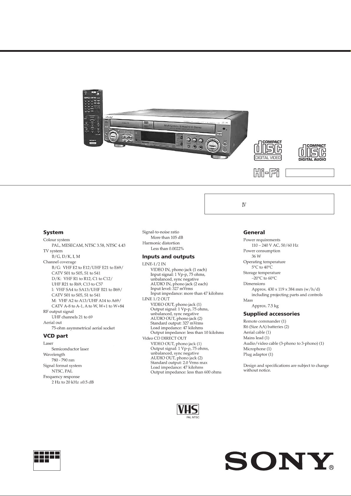
Photo : SLV-7700KME
SPECIFICATIONS
ME Model
SLV-7700KME
E Model
SLV-7700KML
H MECHANISM
•Refer to the SERVICE MANUAL of VHS MECHANICAL
ADJUSTMENT (H MECHA) for MECHANICAL ADJUSTMENTS. (9-973-623-11)
MICROFILM
VIDEO CD PLAYER/
VIDEO CASSETTE RECORDER

SAFETY-RELATED COMPONENT WARNING!!
COMPONENTS IDENTIFIED BY MARK ! OR DOTTED LINE WITH
MARK ! ON THE SCHEMATIC DIAGRAMS AND IN THE PARTS
LIST ARE CRITICAL TO SAFE OPERATION. REPLACE THESE
COMPONENTS WITH SONY PARTS WHOSE PART NUMBERS
APPEAR AS SHOWN IN THIS MANUAL OR IN SUPPLEMENTS
PUBLISHED BY SONY.
SAFETY CHECK-OUT
After correcting the original service problem, perform the following
safety checks before releasing the set to the customer.
1. Check the area of your repair for unsoldered or poorly-soldered
connections. Check the entire board surface for solder splashes
and bridges.
2. Check the interboard wiring to ensure that no wires are
"pinched" or contact high-wattage resistors.
3. Look for unauthorized replacement parts, particularly
transistors, that were installed during a previous repair . Point
them out to the customer and recommend their replacement.
4. Look for parts which, through functioning, show obvious signs
of deterioration. Point them out to the customer and
recommend their replacement.
5. Check the B+ voltage to see it is at the values specified.
6. Flexible Circuit Board Repairing
• Keep the temperature of the soldering iron around 270˚C
during repairing.
• Do not touch the soldering iron on the same conductor of the
circuit board (within 3 times).
• Be careful not to apply force on the conductor when soldering
or unsoldering.
— 2 —

T ABLE OF CONTENTS
SERVICE NOTE
VHS
1. Removal of Drum Assembly ·············································· 5
2. Upper Drum Replacement ·················································· 5
2-1. Removal of Upper Drum ···················································· 5
2-2. Mounting Upper Drum ······················································· 5
3. Periodic Check and Replacement······································· 6
3-1. Cleaning of Rotating Head Disk Assembly························ 6
3-2. Cleaning of the Tape Movement System····························6
3-3. Cleaning the Drive System ················································· 6
VIDEO-CD
1. Removing the Video-CD Mechanism Deck
(When not Energized) ························································ 7
2. Removing the Disc (When not energized) ························· 7
1. GENERAL
Index to parts and controls ························································ 1-1
Getting Started
Step 1: Unpacking ·································································1-2
Step 2: Setting up the remote commander ·····························1-3
Step 3: Connecting the unit ···················································1-3
Step 4: Tuning your TV to this unit ·······································1-3
Step 5: Presetting channels ····················································1-4
Step 6: Setting the clock ························································1-7
Basic Operations – VHS part
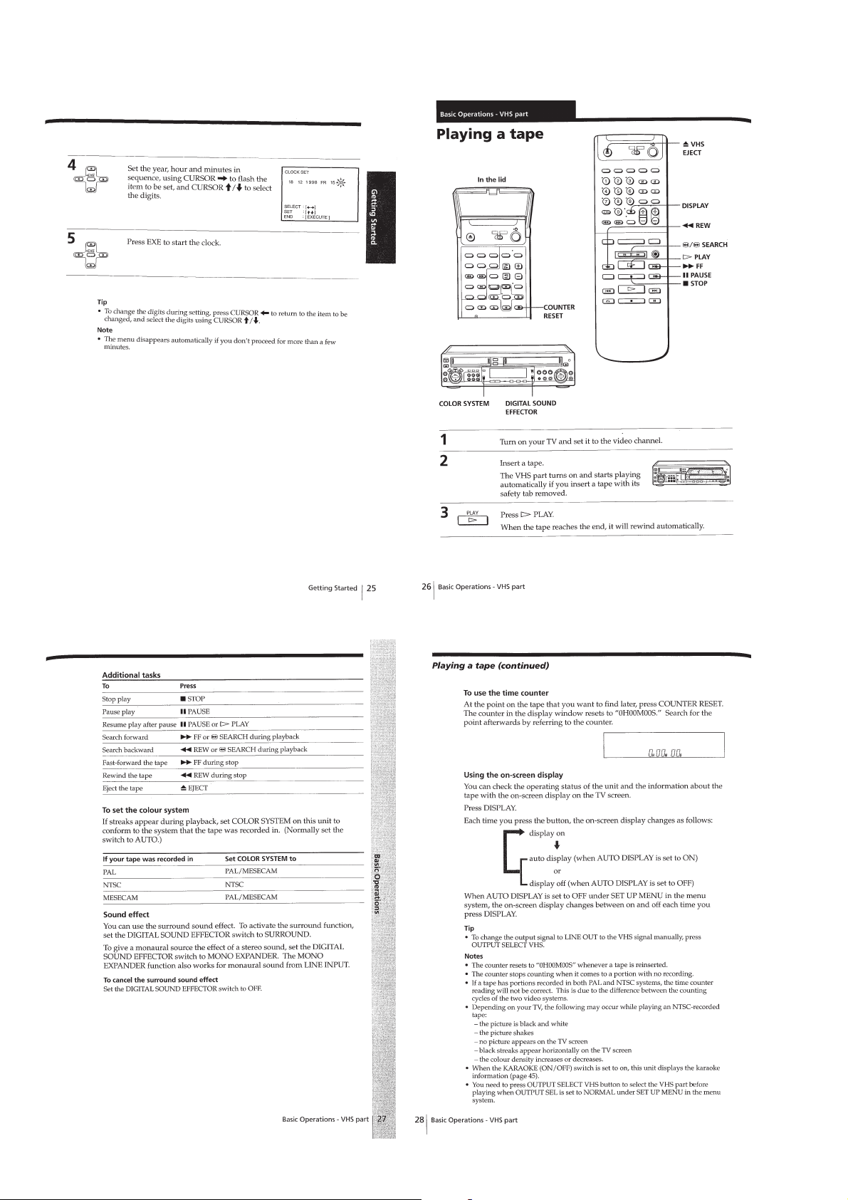
Playing a tape·········································································1-8
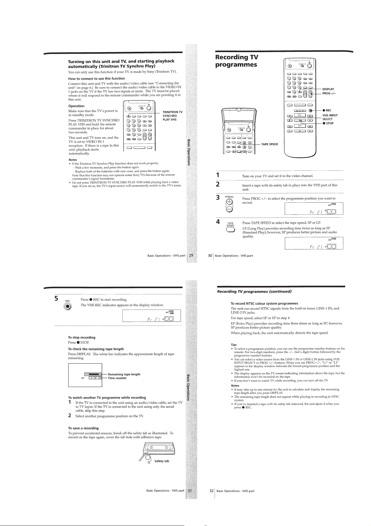
Recording TV programmes ···················································1-9
Recording TV programmes using the timer ························1-10
Basic Operations – VCD part
The VCD part of this unit can play the various discs ·········· 1-10
Playing a VIDEO CD/Audio CD·········································1-10
Using the display window ··················································· 1-11
Basic Operations – Karaoke function
Before you start karaoke ······················································1-12
Karaoke sing-along ······························································1-12
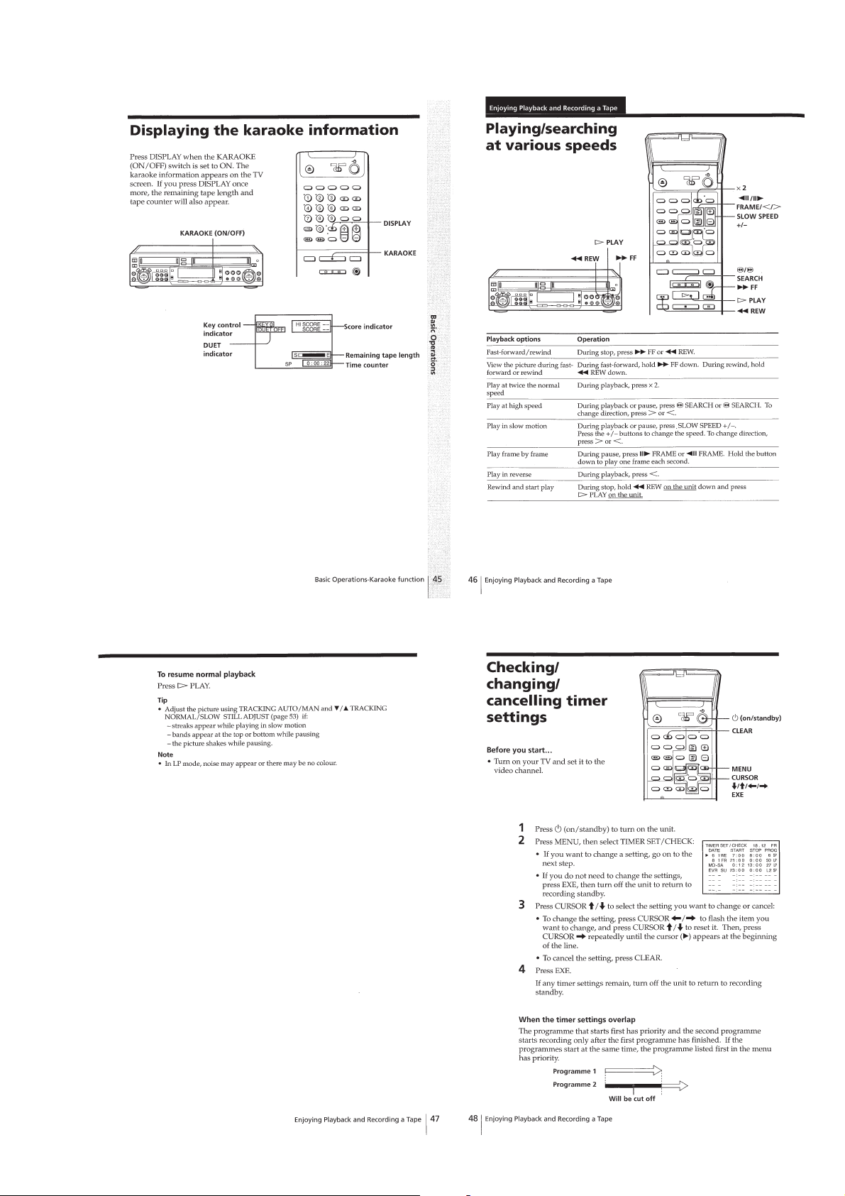
Displaying the karaoke information ····································1-13
Enjoying Playback and Recording a Tape
Playing/searching at various speeds ····································1-13
Checking/changing/cancelling timer settings ······················ 1-13
Editing with another VCR ···················································1-14
Searching with the index function ·······································1-14
Adjusting the picture ···························································1-15
Changing menu options ·······················································1-15
Audio dubbing ·····································································1-15
Enjoying Playback of a VIDEO CD/Audio CD
Locating scenes directly using the scene numbers
(Scene Search) ·····································································1-16
Resuming playback from the point you stopped a
VIDEO CD (Resume Play)··················································1-16
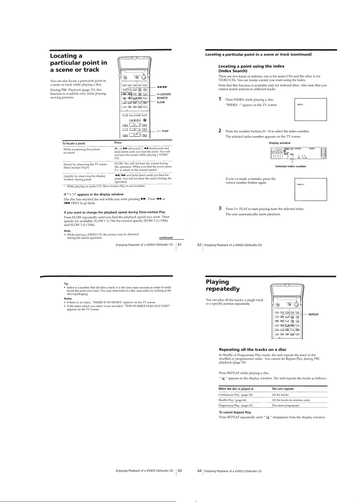
Locating a particular point in a scene or track·····················1-17
Playing repeatedly ······························································· 1-17
Playing a random order (Shuffle Play) ································1-18
Creating your own programme (Programme Play) ·············1-18
Playing a VIDEO CD with PBC functions (PBC Playback)··1-19
Switching the sound·····························································1-19
Enjoying Karaoke Sing-along
Programming the order of the songs····································1-20
Using the various functions ·················································1-20
Recording your karaoke singing ··········································1-21
Additional Information
Precautions···········································································1-21
Troubleshooting ···································································1-22
2. DISASSEMBLY
2-1. Upper Case ······································································2-1
2-2. Front Panel Assy······························································2-1
2-3. Jack Block, MJ-92 Board ················································2-1
2-4. HI-66 Board·····································································2-2
2-5. SW-323 Board, IO-65 Board ··········································· 2-2
2-6. VCD Mechanical Block ··················································2-2
2-7. CD-169 Board ·································································2-2
2-8. PS-418 Board ··································································2-3
2-9. RP-233 Board ·································································· 2-3
2-10. MA-303 Board ································································2-3
2-11. Mechanism Deck ·····························································2-4
2-12. TU-168 Board··································································2-4
2-13. MB-77 Board···································································2-4
2-14. Internal Vie ws··································································2-5
2-15. Circuit Boards Location ··················································2-6
3. SERVICE POSITION
3-1. HI-66, IO-65, SW-323 and MJ-92 Boards ······················3-1
3-2. MA-303, TU-168 and PS-418 Boards·····························3-1
3-3. CD-169 and BD-21 Boards ·············································3-2
3-4. MB-77 Board···································································3-2
4. BLOCK DIAGRAMS
4-1. Overall Block Diagram (1/2)···········································4-1
4-2. Overall Block Diagram (2/2)···········································4-3
4-3. Video Block Diagram ······················································4-5
4-4. Audio Block Diagram ·····················································4-7
4-5. Display Control Block Diagram······································4-9
4-6. Servo/System Control Block Diagram ·························· 4-11
4-7. Karaoke, Audio I/O Block Diagram······························4-13
4-8. Video CD Block Diagram (1/2)·····································4-15
4-9. Video CD Block Diagram (2/2)·····································4-19
4-10. Tuner Block Diagram ····················································4-21
4-11. Power Block Diagram ···················································4-23
5. PRINTED WIRING BOARDS AND
SCHEMATIC DIAGRAMS
5-1. Frame Schematic Diagram ················································5-1
5-2. Printed Wiring Boards and Schematic Diagrams··············5-3
• This Note is Common for Printed Wiring Boards and
Schematic Diagrams····················································5-3
• CD-169 (Video-CD, Mecha Control)
Schematic Diagram (1/2) ································5-5
• CD-169 (Video Encoder)
Schematic Diagram (2/2) ································5-7
• CD-169 (VCD Mecha Control, MPEG)
Printed Wiring Board ······································5-9
• BD-21 (RF AMP), Loading (Loading Motor)
Schematic Diagrams ·····································5-11
• BD-21 (RF AMP), Loading (Loading Motor)
Printed Wiring Boards···································5-13
• RP-233 (Head AMP)
Schematic Diagram ······································· 5-15
• RP-233 (Head AMP)
Printed Wiring Board ····································5-17
• MA-303 (Video/Audio Process, Servo/System Control)
Printed Wiring Board ····································5-19
• MA-303 (Servo/System Control)
Schematic Diagram (1/5) ······························5-21
• MA-303 (CTL, REC/PB Control)
Schematic Diagram (2/5) ······························5-23
• MA-303 (Selector)
Schematic Diagram (3/5) ······························5-25
• MA-303 (Audio Processor)
Schematic Diagram (4/5) ······························5-27
• MA-303 (Y/C Video Process)
Schematic Diagram (5/5) ······························5-29
• MB-77 (Karaoke DSP, Audio I/O)
Printed Wiring Board (Side A)······················5-31
— 3 —

• MB-77 (Karaoke DSP, Audio I/O)
Printed Wiring Board (Side B) ······················ 5-33
• MB-77 (Karaoke DSP)
Schematic Diagram (1/4) ······························5-35
• MB-77 (Audio I/O)
Schematic Diagram (2/4) ······························5-37
• MB-77 (Surround Processor)
Schematic Diagram (3/4) ······························5-39
• MB-77 (Video Select)
Schematic Diagram (4/4) ······························5-41
• HI-66 (Display/Function Control)
Schematic Diagram ······································· 5-43
• HI-66 (Display/Function Control)
Printed Wiring Board ····································5-45
• SW-323 (Function Switch)
Printed Wiring Board ····································5-47
• SW-323 (Function Switch)
Schematic Diagram ······································· 5-48
• MJ-92 (MIC AMP)
Printed Wiring Board ····································5-49
• MJ-92 (MIC AMP)
Schematic Diagram ······································· 5-50
• IO-65 (Front Jack)
Schematic Diagram ······································· 5-51
• IO-65 (Front Jack)
Printed Wiring Board ····································5-53
• TU-168 (Tuner)
Schematic Diagram ······································· 5-55
• TU-168 (Tuner)
Printed Wiring Board ····································5-57
• PS-418 (Power Supply)
Schematic Diagram ······································· 5-59
• PS-418 (Power Supply)
Printed Wiring Board ····································5-61
• Waveforms ·································································5-63
6. INTERFACE AND IC PIN FUNCTION
6-1. System Control -Video Block Interface ··························6-1
6-2. System Control -Servo Peripheral Circuit Interface········6-2
6-3. System Control -Mechanism Interface····························6-3
6-4. System Control -System Control
Peripheral Circuit Interface ·············································6-4
6-5. System Control -Hi-Fi Audio Block Interface ················ 6-4
6-6. System Control -Normal Audio Block Interface ·············6-4
6-7. AV Control -Input Selection Block Interface ··················6-5
6-8. Servo/System Control Microprocessor
Port Function Description ··············································· 6-6
6-9. Display/Function Control Microprocessor
Port Function Description ··············································· 6-7
6-10. Video-CD Mechanism Control Microprocessor
Port Function Description ··············································· 6-8
6-11. MPEG Decoder Port Function Description···················6-10
6-12. Video Encoder Port Function Description·····················6-12
6-13. Karaoke/Digital Sound Processor
Port Function Description ············································· 6-14
2-3. Power Supply Check ·······················································7-3
2-3-1.Output V oltage Check······················································7-3
2-4. Video-CD System Adjustments·······································7-3
2-4-1.S-Curve Check ································································7-3
2-4-2.RF Level Check ·······························································7-4
2-4-3.E-F Balance (Traverse) Check ········································7-4
2-4-4.RF PLL Free-run Frequency Check ································7-5
2-4-5.Clock Adjustment ····························································7-5
2-5. Servo System Adjustment ···············································7-5
2-5-1.RF Switching Position Adjustment ·································7-5
2-6. Video System Adjustments··············································7-6
2-6-1.X'tal OSC Check ·····························································7-6
2-6-2.SYNC AGC Check ··························································7-6
2-6-3.White Clip/Dark Clip Check ···········································7-6
2-6-4.REC Y Level Check ························································7-7
2-6-5.REC Chrome Level Check ··············································7-7
2-6-6.Playback Level Check ·····················································7-7
2-6-7.VCO Frequency Adjustment ···········································7-7
2-7. Audio System Adjustments ·············································7-8
2-7-1.AF Switching Position Adjustment ································· 7-8
2-7-2.VCO f
2-7-3.Deviation Check ······························································7-9
2-7-4.Band Pass Filter f0 Adjustment ········································7-9
2-7-5.ACE Head Adjustment ·················································· 7-10
2-7-6.Recording Bias Check ···················································7-10
2-7-7.E-E Output Level Check ··············································· 7-10
2-7-8.Overall Output Level and Distortion Factor Check·······7-10
2-7-9.Overall Noise Level Check············································7-10
2-8. Adjustment Parts Location Diagrams····························7-11
Adjustment·························································· 7-9
0
8. REPAIR PARTS LIST
8-1. EXPLODED VIEWS ······················································8-1
8-1-1.Case Assembly ································································8-1
8-1-2.Front Panel Assembly······················································8-2
8-1-3.Chassis Assembly ····························································8-3
8-1-4.VCD Mechanical Deck Assembly (CDM14-5BD21) ·····8-4
8-1-5.Optical Pick-up Assembly (BU-5BD21)·························8-5
8-1-6.VHS Mechanical Deck Assembly (1) ·····························8-6
8-1-7.VHS Mechanical Deck Assembly (2) ·····························8-7
8-1-8.VHS Mechanical Deck Assembly (3) ·····························8-8
8-1-9.VHS Mechanical Deck Assembly (4) ·····························8-9
8-2. ELECTRICAL PARTS LIST ········································8-10
7. ADJUSTMENTS
7-1. MECHANICAL ADJUSTMENTS································· 7-1
7-2. ELECTRICAL ADJUSTMENTS ···································7-1
2-1. Preparation Before Adjustment ·······································7-1
2-1-1.Equipment Required ························································7-1
2-1-2.Equipment Connection ····················································7-1
2-1-3.Check of Input Signal ······················································7-1
2-1-4.Alignment Tape ·······························································7-2
2-1-5.Specified Input -Output Level and the Impedance··········7-2
2-1-6.Adjustment Procedures···················································· 7-2
2-2. Video-CD Color-Bars Mode············································7-2
— 4 —

SERVICE NOTE
y
y
VHS
1. REMOVAL OF DRUM ASSEMBLY (Fig.1.)
1) Remove the screw 1 (P3×8)
2) Remove the shaft ground assembly 2.
3) Remove three screws 3 (P3×6).
4) Remove the drum assembly 4.
Note: When attaching the drum assembly, be careful not to blur the
contacting surface with fingerprint or like.
When attaching the shaft ground assembly, be careful not apply
force to the spring section of it.
2
shaft ground assembl
1
screw
(P3
×
8)
4
drum assembly
SLV-7700KME/7700KML
1
screw (P3 × 8)
2
shaft ground assembl
solders
3
three screws
×
(P3
6)
Fig. 1.
2. UPPER DRUM REPLACEMENT
2-1. Removal of Upper Drum (Fig. 2.)
1) Remove the screw 1 (P3×8).
2) Remove the shaft ground assembly 2.
3) Completely remove the rotary upper drum board and desolder
the soldering indicated by the arrows. (16 points)
4) Remove the screws 3 (PSW 3 ×8) and tape out the rotary upper
drum assembly in the direction of arrow. (See Fig. 3.)
If it is difficult, remove by shaking the rotary upper drum
gradually.
Note: If the drum can not be removed, check whether the solders ha ve
been removed or mot again.
solders
Fig. 2.
Note: When inserting the rotary upper drum assembly into the lower
drum, be careful not to blur the contacting surface with
fingerprint or like.
2) If it is difficult, mount the upper drum by shaking it gradually.
Note: Be careful not to damage the head. Make sure that the upper
drum is tightly inserted.
3) Tighten two screws 3 (PSW 3×8). (See Fig. 3.)
Note: Temporary tighten two screws, After making sure that upper
drum is tightly inserted, tighten the screws.
3
two screws
(PSW3 × 8)
rotary upper drum assembly
DZR-68-R
2-2. Mounting Upper Drum
1) Mount the rotary upper drum assembly by aligning marked b
with marked of rotary transformer board (lower drum) so
that the screw holes of both upper and lower drums match.
rotary transformer
board
Fig. 3.
— 5 —

4) Solder 16 points on the rotary upper drum board. (See Fig. 2.)
5) Fix the shaft ground assembly 2 using the screw 1 (P3×8) so
that the protrusion of the shaft ground assembly end contacts
the center of the drum shaft, (See Fig. 2.)
Note: When attaching the shaft ground assembly, be careful not to
apply force to the spring section of it.
6) Tighten the screw 1 (P3×8). (See Fig. 2.)
3. PERIODIC CHECK AND REPLACEMENT
(Refer to the VHS MECHANICAL ADJUSTMENT
(H MECHA) MANUAL.)
In order to obtain the best performance from this unit and make full
use of its capabilities, and to extend the life of the unit and tapes, it
is recommended that the following periodic checks and maintenance
be performed.
• The following must be done after every repair reg ardless of how
many hours the user has operated the machine.
3-1. CLEANING OF ROTATING HEAD DISK ASSEMBLY
1) Press a chamois cloth which has been dipped in cleaning fluid
lightly against the rotating drum assembly, then do the cleaning
by slowly rotating the rotating head disk by hand. (Nev er try to
clean by using the motor to turn it.)
2) Never try to clean by moving the chamois cloth at a vertical
angle to the head tip. There is a very great danger of damaging
the head tip if this is done.
3-2. CLEANING OF THE TAPE MOVEMENT SYSTEM
1) Clean the surfaces which the tape contacts during its movement
(tapeguide, drum assembly surface, capstan, pinch roller, etc.)
with a chamois cloth that has been dipped in cleaning fluid.
3-3. CLEANING THE DRIVE SYSTEM
1) Clean the driving parts with a cloth that been dipped in cleaning
fluid.
No.4 guide
(TG4)
No.3 guide
(TG3)
FE head
No.2 guide
(TG2)
No.1 guide
(TG1)
No.0 guide
(TG0)
No.5 guide
(TG5)
No.6 guide
(TG6)
ACE head
No.7 guide
(TG7)
capstan shaft
No.8 guide
(TG8)
pinch roller
Fig. 4. Parts requiring cleaning
— 6 —

VIDEO-CD
s
1. REMOVING THE VIDEO-CD MECHANISM DECK (WHEN NOT ENERGIZED)
1 Remove three screws securing the mechanism deck.
2 Undo seven claws on the front panel to lift the front panel.
1
three screws
3
Lift the mechanism deck as inclined
toward you and remove the deck
together with the front panel.
2
three claws
2
two claw
2
two claws
4 Remove harness of CDM-14 board and flat cable of BD-21 board.
2. REMOVING THE DISC (WHEN NOT ENERGIZED)
1
Turn the cam to the direction of arrow
(counter clock wise) by tapering driver.
loading panel
Take off the disc table.
2
Remove the loading panel from the disc table.
3
Remove the front panel from the mechanism deck.
— 7 —

SECTION 1
GENERAL
SLV-7700KME/7700KML
This section is extracted from
instruction manual.
1-1

1-2

1-3

1-4

1-5

1-6

1-7
1-8
1-9

1-10

1-11

1-12
1-13

1-14

1-15

1-16
1-17

1-18

1-19

1-20

1-21

1-22E

SECTION 2
SLV-7700KME/7700KML
DISASSEMBLY
NOTE: Follow the disassembly procedure in the numerical order given.
2-1. UPPER CASE 2-2. FRONT PANEL ASSY
5
1
Push the
power button.
2
Push the
open/close
button.
3
claws
tapping screws
4
loading panel
7
claw
8
upper case
6
tapping screws
7
9
claws
5
CN301
6
claws
CN780
4
CN603
2
CN604
!º
CN901
1
CN705
8
claws
3
CN704
2-3. JACK BLOCK, MJ-92 BOARD
5
bind tapping screws
4
coating lead pin
3
claws
(B2.6
2
CN304
×
8)
1
CN601
6
bind tapping screws
(B2.6
7
Jack block
×
8)
8
bind tapping screws
(B2.6
9
!º
×
8)
front ground plate (A)
MJ-92 board
2-1
 Loading...