

Sony xci-sx100, xci-sx100c, sci-v100, sci-v100c Operating Instructions Manual
4-115-799-12 (1)
Intelligent Camera
Operating Instructions
Before operating the unit, please read this manual thoroughly and
retain it for future reference.
XCI-SX100/SX100C
XCI-V100/V100C
2008 Sony Corporation
Printed in Japan
Owner’s Record
The model and serial numbers are located on the bottom. Record the
serial number in the space provided below. Refer to these numbers
whenever you call upon your Sony dealer regarding this product.
Model No. ____ _________ Serial No. ___ ____ ____ ___
WARNING
To reduce the risk of re or electric shock, do not
expose this apparatus to rain or moisture.
To avoid electrical shock, do not open the cabinet.
Refer servicing to qualied personnel only.
IMPORTANT
The nameplate is located on the bottom.
Power Supply Caution for U.S.A. and CANADA
The unit must always be operated with a rated 12V dc, minimum 2A,
Class 2 power supply or limited power sources.
In the USA, use an UL Listed power supply.
In Canada, use a CSA-certied power supply.
For the customers in the U.S.A.
This equipment has been tested and found to comply with the limits
for a Class A digital device, pursuant to Part 15 of the FCC Rules.
These limits are designed to provide reasonable protection against
harmful interference when the equipment is operated in a
commercial environment. This equipment generates, uses, and can
radiate radio frequency energy and, if not installed and used in
accordance with the instruction manual, may cause harmful
interference to radio communications. Operation of this equipment
in a residential area is likely to cause harmful interference in which
case the user will be required to correct the interference at his own
expense.
You are cautioned that any changes or modications not expressly
approved in this manual could void your authority to operate this
equipment.
All interface cables used to connect peripherals must be shielded in
order to comply with the limits for a digital device pursuant to Subpart
B of Part 15 of FCC Rules.
Note: This camera is not intended for use in security applications in the
meaning of the European standard series EN 50132 (Alarm systems CCTV surveillance systems for use in security applications).
For the customers in Europe
The manufacturer of this product is Sony Corporation, 1-7-1 Konan,
Minato-ku, Tokyo, Japan.
The Authorized Representative for EMC and product safety is Sony
Deutschland GmbH, Hedelnger Strasse 61, 70327 Stuttgart, Germany.
For any service or guarantee matters please refer to the addresses
given in separate service or guarantee documents.
This apparatus shall not be used in the residential area.
For the customers in Europe, Australia and New Zealand
WARNING
This is a Class A product. In a domestic environment, this product may
cause radio interference in which case the user may be required to take
adequate measures.
In the case that interference should occur, consult your nearest
authorized Sony service facility.
AVERTISSEMENT
An de réduire les risques d’incendie ou
d’électrocution, ne pas exposer cet appareil à la
pluie ou à l’humidité.
An d’écarter tout risque d’électrocution, garder
le coret fermé. Ne coner l’entretien de l’appareil
qu’à un personnel qualié.
IMPORTANT
La plaque signalétique se situe sous l’appareil.
Pour les clients en Europe
Le fabricant de ce produit est Sony Corporation, 1-7-1 Konan, Minatoku, Tokyo, Japon.
Le représentant autorisé pour EMC et la sécurité des produits est
Sony Deutschland GmbH, Hedelnger Strasse 61, 70327 Stuttgart,
Allemagne. Pour toute question concernant le service ou la garantie,
veuillez consulter les adresses indiquées dans les documents de service
ou de garantie séparés.
Ne pas utiliser cet appareil dans une zone résidentielle.
Pour les utilisateurs en Europe, Australie et Nouvelle-Zélande
AVERTISSEMENT
Il s’agit d’un produit de Classe A. Dans un environnement domestique,
cet appareil peut provoquer des interférences radio, dans ce cas
l’utilisateur peut être amené à prendre des mesures appropriées.
Précautions à prendre avec l’alimentation électrique pour les
ETATS-UNIS et le CANADA
L’unité doit toujours être utilisée avec un courant cc nominal de 12
V, minimum 2A, une alimentation électrique Classe 2 ou des sources
d’alimentation électrique limitées.
Aux Etats-Unis, utiliser une alimentation électrique UL répertoriée.
Au Canada, utiliser une alimentation électrique certiée CSA.
Notes on Operation
Power supply
The camera module is operated with a +12 V DC. If the power supply is
insucient, use the stable power with less ripple or noise.
Foreign bodies
Be careful not to spill liquids, or drop any ammable or metal objects in the
camera body.
Locations for operation and storage
Avoid operation or storage in the following places.
Extremely hot or cold locations. Recommended temperature range is 0°C to
40°C (32°F to 104°F)
Locations subject to strong vibration or shock
Near generators of strong electromagnetic radiation such as TV or radio
transmitters
Care
Use a blower to remove dust from the surface of the lens or optical lter. Clean
the exterior with a sof t, dry cloth.
If the camera is very grimy, apply a cloth soaked in a mild detergent then wipe
with a dry cloth. Do not apply organic solvents such as alcohol which may
damage the nish.
Data and security
You should keep in mind that the images or audio you are monitoring may be
protected by privacy and other legal rights, and the responsibility for making
sure you are complying with applicable laws is yours alone.
OS
This camera does not support any OS as the factory setup. When you turn on
the power, only the BIOS screen is displayed.
Note on laser beams
Laser beams may damage a CCD. You are cautioned that the surface of a
CCD should not be exposed to laser beam radiation in an environment
where a laser beam device is used.
Overview
The XCI-SX100/SX100C/V100/V100C lineup include an intelligent monochrome
cameras (XCI-SX100/V100) and intelligent color cameras (XCI-SX100C/V100C)
that can capture and process pictures, as well as peripheral devices.
High image quality
These cameras produce high-resolution images of 1,250,000 pixels with the XCISX100/SX100C (SXGA) and 330,000 pixels with the XCI-V100/V100C (VGA), using
progressive scan CCDs. As square pixels are adopted, images can be processed
using the original aspect ratio without conversion procedure.
Electronic shutter function
Shutter speed can be selected from among a variety of available speeds.
External trigger shutter function (2 to 1/50,000 sec.)
You can obtain a freeze frame by inputting an external trigger signal. This
function is useful for shooting a fast-moving object clearly.
Partial scan
The camera module can limit the eective video output area to achieve high
frame rates, enabling high-speed image processing.
Binning (XCI-SX100/V100 only)
By binning two pixels that align vertically or horizontally, you can acquire a
frame rate twice that of the normal mode vertically, and sensitivity twice that of
the normal mode vertically and horizontally.
High-resolution images (XCI-SX100C/V100C only)
XCI-SX100C/V100C has a color interpolation algorithm that produces highresolution images.
Auto iris
With the lens-control signal output from the 6-pin auto iris port, the camera
module can control a connected DC iris lens. If you remove the C-mount
adaptor, the camera module can support a CS-mount DC iris lens.
Built-in processor
x86 CPU
512 MB DDR2-SDRAM
PC standard input/output interface
LAN connector
VGA monitor, analog RGB output
Hi-speed USB connector
Body xing
Four screw holes to be used to install the camera are provided both on the top
and the bottom of the camera. Installing the camera module on the front panel
minimizes deviation of the optical axis.
Tripod
You can mount the camera on a tripod by tightening the tripod screws.
Phenomena Specic to CCD Image Sensors
The following phenomena that may appear in images are specic to CCD (Charge
Coupled Device) image sensors. They do not indicate malfunctions.
White ecks
Although the CCD image sensors are produced with high-precision
technologies, ne white ecks may be generated on the screen in rare cases,
caused by cosmic rays, etc.
This is related to the principle of CCD image sensors and is not a malfunction.
The white ecks especially tend to be seen in the following cases:
when operating at a high environmental temperature
when you have raised the gain (sensitivity)
when using the slow shutter
Vertical smear
When an extremely bright object, such as a strong spotlight or ashlight, is
being shot, vertical tails may be produced on the screen, or the image may be
distorted.
Monitor screen
Vertical tails shown on the
image.
Bright object
(e.g. strong spotlight,
strong reected light,
ashlight, the sun)
Aliasing
When ne patterns, stripes, or lines are shot, they may appear jagged or icker.
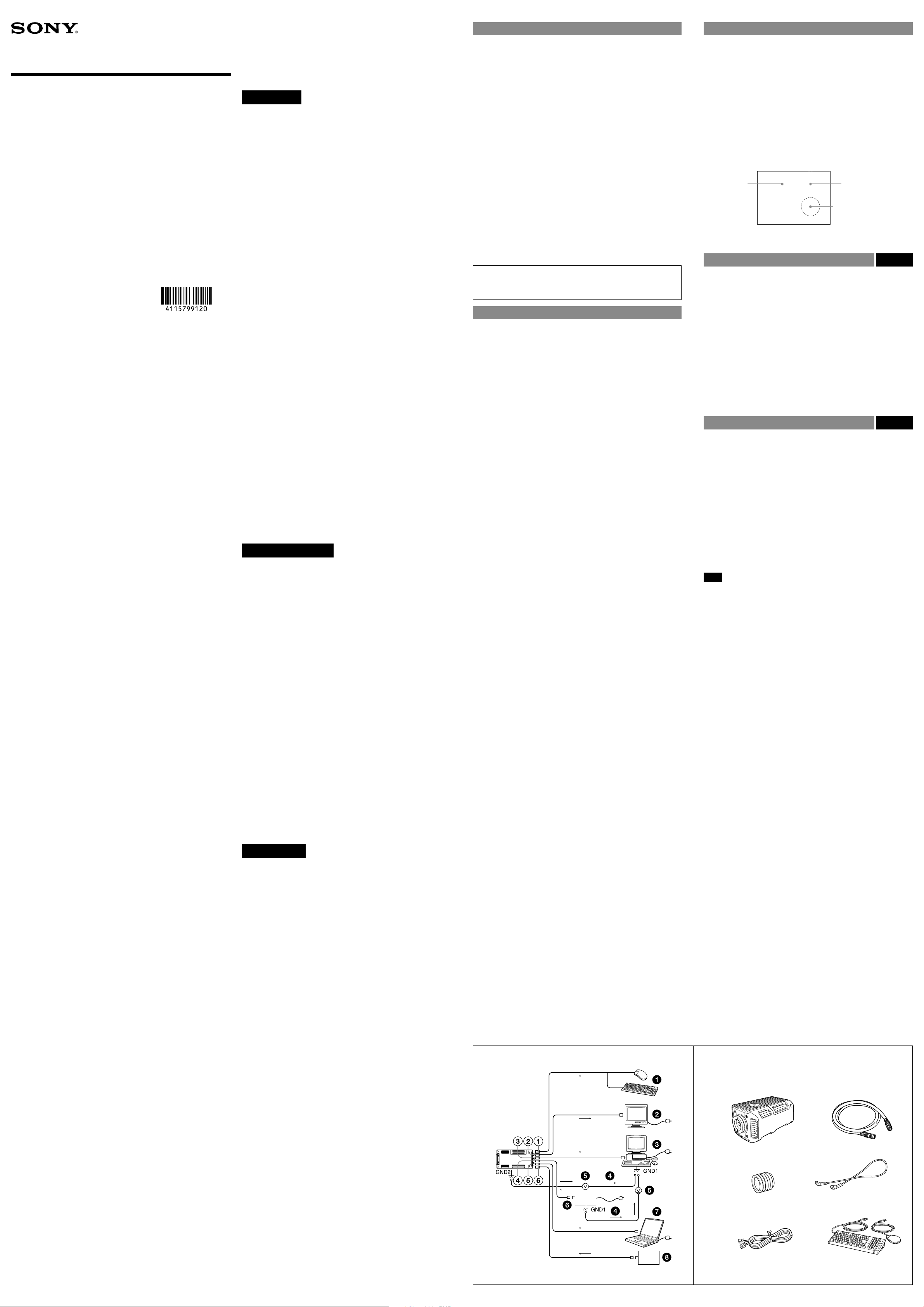
When Installing the Camera Fig. A
When you install the camera with various peripheral devices and if the devices
have dierent ground electric potential, ground only one device. In case there
is a ground electric potential dierence, the camera may be damaged.
Hi-speed USB connector
MONITOR connector
LAN connector
DC IN connector
SERIAL connector
DIGITAL I/O connector
USB mouse/keyboard
Monitor
Host device
Abnormal electricity
Ground electric potential dierence
Power supply
Camera control device
DIGITAL I/O control device
System Components Fig. B
An Intelligent Camera XCI-SX100/SX100C/V100/V100C system can include the
following optional products.
Intelligent Camera
This is a compact, high-resolution camera using progressive-scan CCD image
sensors.
CCXC-12P02N (2 m, 6.6 ft)/05N (5 m, 16.4 ft)/10N (10 m, 32.8 ft)/25N (25 m,
82 ft) camera cable (not supplied)
This is attached to the DC IN connector of the camera and is used for power
supply and trigger-signal input/output.
Lens (commercially available)
Use a lens appropriate for the camera module and your needs.
Fall-prevention wire
This is attached to one of the auxiliary holes (top), using the supplied screw.
LAN cable (enhanced category 5) (commercially available)
This is attached to the LAN connector of the camera and is used to access a
network.
Note
Do not connect the LAN cable to a network where excess voltage is present.
USB mouse/keyboard (commercially available)
Use a mouse or keyboard that supports USB.
(continued on the reverse side)se side)e side)
WARNUNG
Um die Gefahr von Bränden oder elektrischen
Schlägen zu verringern, darf dieses Gerät nicht
Regen oder Feuchtigkeit ausgesetzt werden.
Um einen elektrischen Schlag zu vermeiden, darf
das Gehäuse nicht geönet werden. Überlassen
Sie Wartungsarbeiten stets nur qualiziertem
Fachpersonal.
WICHTIG
Das Namensschild bendet sich auf der Unterseite des Gerätes.
Für Kunden in Europa
Der Hersteller dieses Produkts ist Sony Corporation, 1-7-1 Konan,
Minato-ku, Tokyo, Japan.
Der autorisierte Repräsentant für EMV und Produktsicherheit ist Sony
Deutschland GmbH, Hedelnger Strasse 61, 70327 Stuttgart, Deutschland.
Bei jeglichen Angelegenheiten in Bezug auf Kundendienst oder Garantie
wenden Sie sich bitte an die in den separaten Kundendienst- oder
Garantiedokumenten aufgeführten Anschriften.
Dieser Apparat darf nicht im Wohnbereich verwendet werden.
Für Kunden in Europa, Australien und Neuseeland
WARNUNG
Dies ist eine Einrichtung, welche die Funk-Entstörung nach Klasse
A besitzt. Diese Einrichtung kann im Wohnbereich Funkstörungen
verursachen; in diesem Fall kann vom Betreiber verlangt werden,
angemessene Maßnahmen durchzuführen und dafür aufzukommen.
Camera

-1
-2
-3
-4
Board made of wood,
resin, etc.
Metal plate
Ceiling
Metal plate
Board made of wood,
resin, etc.
Screw
Eject button
Screw (supplied)
Locations and Functions of Parts and Operations
Front/Top/Bottom Fig. C
Lens mount (C-mount/CS-mount)
Attach any C-mount or CS-mount lens, or other optical equipment.
Note
The lens must not project more than the following length-values from the lens
mount.
Lens mount face
C-mount: 10 mm (13/32 inch) or less
CS-mount: 5 mm (7/32 inch) or less
Fall-prevention wire screw holes (top)/auxiliary reference screw holes
(top)
Tripod screw holes (top/bottom)
CF card slot cover/CF card slot (internal)
Reference holes (bottom)
These precision screw holes are for locking the camera in place. Using these
holes secures the optical axis alignment.
For details, refer to the Technical Manual.
Rear Fig. D
MONITOR (monitor output) connector (15-pin, female)
You can connect a monitor cable to this connector and display an image on a
multiscan monitor.
Pin No. No.No. Signal Pin No. Signal
1 R OUT 9 NC
2 G OUT 10 GND
3 B OUT 11 NC
4 NC 12 NC
5 GND 13 HD OUT
6 GND 14 VD OUT
7 GND 15 NC
8 GND
DIGITAL I/O connector (15-pin, male)
You can connect a DIGITAL I/O cable to this connector to transmit and receive
data between the camera module and the control device.
Pin No. No.No. Signal Pin No. Signal
1 ISO_IN1 9 ISO_OUT4
2 ISO_IN2 10 ISO_OUT_COM1
3 ISO_IN3 11 ISO_OUT5
4 ISO_IN4 12 ISO_OUT6
5 ISO_IN_COM 13 ISO_OUT7
6 ISO_OUT1 14 ISO_OUT8
7 ISO_OUT2 15 ISO_OUT_COM2
8 ISO_OUT3
Hi-speed USB connector
You can connect a USB mouse/keyboard via this connector to control a camera.
Pin No. No.No. Signal Pin No. Signal
1 VBUS 3 D+
2 D– 4 GND
SERIAL / Auto iris connector (6-pin)
You can connect a serial cable to this connector to control a camera from a
camera- control device.
You can connect a DC iris lens to control the lens from a camera.
Pin No. No.No. Signal Pin No. Signal
1 TXD 4 IRIS_CONTROL–
2 RXD 5 IRIS_CONTROL+
3 GND 6 IRIS_DRIVE+
DC IN (DC power input) connector (12-pin)
You can connect a camera cable (not supplied) to this connector to input the
+12 V DC power supply.
Pin No. No.No. Signal Pin No. Signal
1 GND 7 NC
2 VCC 8 GND
3 GND 9 VCC
4 NC 10 Exposure pulse output
5 GND 11 Trigger pulse input
6 NC 12 GND
MODE switches
For service use. Both switches are set to the left side as the factory setup.
Note
If either of these switches is set to the right side, the camera will not start
normally.
RESET switch
Hardware reset. Push to restart the camera.
STATUS LED
Lights in red when the BIOS is starting up.
POWER LED
Lights in green when power is turned on.
LAN connector
You can connect a LAN cable to this connector to input/output a video signal
to/from the host device/the camera.
Pin No. No.No. Signal Pin No. Signal
1 TRD+ (0) 5 TRD– (2)
2 TRD– (0) 6 TRD– (1)
3 TRD+ (1) 7 TRD+ (3)
4 TRD+ (2) 8 TRD– (3)
CAUTION
For safety, do not connect the connector for peripheral device wiring
that might have excessive voltage to this port. Follow the instructions
for this port.
CAUTION
When you connect the LAN cable of the unit to peripheral device, use a
shielded-type cable to prevent malfunction due to radiation noise.
ATTENTION
Par mesure de sécurité, ne raccordez pas le connecteur pour le câblage
de périphériques pouvant avoir une tension excessive à ce port. Suivez
les instructions pour ce port.
ATTENTION
Lors de la connexion du câble LAN de l’appareil au périphérique,
utilisez un câble blindé an d’empêcher tout dysfonctionnement dû au
bruit de rayonnement.
VORSICHT
Aus Sicherheitsgründen nicht mit einem Peripheriegerät-Anschluss
verbinden, der zu starke Spannung für diese Buchse haben könnte.
Folgen Sie den Anweisungen für diese Buchse.
VORSICHT
Verwenden Sie beim Anschließen des LAN-Kabels des Geräts an ein
Peripheriegerät ein abgeschirmtes Kabel, um Fehlfunktionen aufgrund
von Störungen zu vermeiden.
Installation
Notes on installing the camera
The camera body is designed to externally dissipate heat built up internally
during operation.
Install the camera as shown below to promote heat dissipation and retain
optimum per formance of the camera.
using a suspension support (-1)
using a tripod (-2)
using a metal plate (-3)
Note
Do not attach to a board made of wood, resin, etc. that may block heat
dissipation. (-4)
Inserting the CF memory card Fig. F
1 Loosen the two screws and remove the cover.
2 Press the eject button and insert the CF card slot.
3 Mount the cover to the camera module, pressing the CF card slot with the
cover inside.
4 Fasten the two screws to secure the cover.
Fitting the CS-mount lens Fig. G
This camera module supports a C-mount lens as the factory setup. If you will be
using a CS-mount lens, perform the following steps:
1 Insert two 3– mm Allen wrenches (commercially available) through the
screw-recess holes of the C-mount adaptor.
2 Turn the Allen wrenches counterclockwise.
3 Remove the C-mount adaptor.
If you need to use the C-mount adaptor again, follow steps 1 to 3 in reverse
order.
Note
When you t the C-mount adaptor again after removal, a ange focal length
may change.
Attaching the fall-prevention wire Fig. H
1 Attach the fall-prevention wire (not supplied) to the camera module, using
the supplied screw.
2 Attach the other end of the fall-prevention wire to a junction box, etc. (screw
not supplied)
Note
The fall-prevention wire is very important for fall prevention. Perform the
procedure correctly.
Use the screws supplied with the XCI-SX100/SX100C/V100/V100C. Using other
than the supplied screws may cause damage inside the camera module.
Warning
If you want to install the camera at a height such as on a ceiling, entrust the
installation to an experienced contractor or installer.
If you install the camera at a height, ensure that the installation location and
its material are strong enough to withstand a weight, and then install the
camera securely. If they are not strong enough, the camera may fall and cause
serious injury.
To prevent the camera from falling, be sure to attach the supplied wire rope.
If you install the camera at a height, check periodically, at least once a year, to
ensure that the connection has not loosened. If conditions warrant, perform
this periodic check more frequently.
Connecting the camera cable Fig. I
Connect the camera cable to the DC IN connector.
Also, if needed, connect the LAN cable to the LAN connector, the monitor
cable to the MONITOR connector, the serial cable to the SERIAL connector, the
DIGITAL I/O cable to the DIGITAL I/O connector, and the USB mouse/keyboard
to one of the USB connectors respectively. When you connect the monitor cable
or DIGITAL I/O cable, plug the cable connector into the monitor connector or
DIGITAL I/O connector until they snap into place, holding them.
Then tighten the xing screws placed on both sides of the cable connector.
Monitor cable
USB cable
LAN cable
DIGITAL I/O cable
Camera cable
Serial cable
Connect the other end of to the power supply.
Also, if needed, connect to the monitor, to the host device, to the
DIGITAL I/O control device, and to the camera control device.
Note
Looseness of the xing screws may cause poor connection and damage the
camera module or cables.
Fasten the xing screws.
MONITOR connector
Hi-speed USB connector
LAN connector
DIGITAL I/O connector
SERIAL connector
DC IN connector
Using a tripod
Use a tripod screw with a protrusion extending from the installation surface,
as follows, and tighten it, using a screwdriver.
: 4.3 mm to 5 mm (0.17 inches to 0.20 inches)4.3 mm to 5 mm (0.17 inches to 0.20 inches)
Specications
Imaging sensor system
Pickup device XCI-SX100/SX100C: 1/3 type Interline CCD; 1,250,000
XCI-V100/V100C: 1/3 type Interline CCD; 330,000
Output picture elements (horizontal/vertical)
XCI-SX100/SX100C: 1,280 × 960
XCI-V100/V100C: 640 × 480
Chip size (horizontal/vertical)
XCI-SX100/SX100C: 6.26 mm × 5.01 mm
XCI-V100/V100C: 5.79 mm × 4.89 mm
Unit cell size (horizontal/vertical)
XCI-SX100/SX100C: 3.75 μm × 3.75 μm
XCI-V100/V100C: 7.4 μm × 7.4 μm
CCD vertical drive frequency
XCI-SX100/SX100C: 29.7 kHz
XCI-V100/V100C: 46.154 kHz
CCD horizontal drive frequency
XCI-SX100/SX100C: 49.302 MHz
XCI-V100/V100C: 36.0 MHz
LUT 10-bit input/10-bit output
Five default tables (γ=1, 0.45, 2.2 / binarization /
Shutter speed Monitoring mode: 2 to 1/100,000 sec.
External trigger mode: 2 to 1/50,000 sec.
Processor and interface system
CPU Compatible x86
Internal Operating Frequency: 1 GHz
MMX, SSE, SSE2, SSE3
L1 caches 64 KB × 2/L2 caches 128 KB
Memory Type: DDR2-400
Size: 512 MB
LAN 10Base-T/100Base-TX/1000Base-T
USB Hi-speed USB
Optical system and others
Lens mount C-mount/CS-mount
Flange focal length 17.526 mm (in air)/12.5 mm (in air)
Video output VGA to UXGA
Vertical frequency: 60 Hz
Sensitivit y XCI-SX100/V100: 400 lx, F5.6
XCI-SX100C/V100C: 2,000 lx, F5.6
Minimum illumination XCI-SX100/V100: 2 lx or less
(gain: +18 dB, F1.4)
XCI-SX100C/V100C: 20 lx or less
(gain: +18 dB, F1.4)
Gain 0 dB to +18 dB
Read mode Normal mode
Binning mode (XCI-SX100/V100 only)
Partial scan mode
Shutter External trigger shutter
Power +12 V DC (range: 10.5 V to 26.4 V)
Power consumption XCI-SX100/V100: 17.4 W
XCI-SX100C/V100C: 18.2 W
Operating temperature –5 °C to +45 °C (23 °F to 113 °F)
Storage temperature –30 °C to +60 °C (–22 °F to 140 °F)
Operating temperature humidity
20 % to 80 % (no condensation)
Storage temperature humidity
20 % to 95 % (no condensation)
Vibration resistance 10 G (20 Hz to 200 Hz, when using the reference
Shock resistance 70 G
External dimension (w/h/d) 94 × 70 × 140 mm (3 3/4 × 2 7/8 × 5 5/8 inches), not
Mass 760 g (1 lb 11 oz)
Accessories Lens mount cap (1)
Fall-prevention wire (1)
Screw M3 × 8 for fall-prevention wire (1)
Operating Instructions (1)
Design and specications are subject to change without notice.
IMPORTANT
The nameplate is located on the bottom.
Note
Always verify that the unit is operating properly before use. SONY WILL
NOT BE LIABLE FOR DAMAGES OF ANY KIND INCLUDING, BUT NOT LIMITED
TO, COMPENSATION OR REIMBURSEMENT ON ACCOUNT OF THE LOSS OF
PRESENT OR PROSPECTIVE PROFITS DUE TO FAILURE OF THIS UNIT, EITHER
DURING THE WARRANTY PERIOD OR AFTER EXPIRATION OF THE WARRANTY,
OR FOR ANY OTHER REASON WHATSOEVER.
square pixels with alignment
square pixels with alignment
negative-positive inversion)
holes)
including projecting parts
About the Technical Manual
The Operating Instructions describe the functions and use of this product.
For more details, see the
Please ask your sales representative about the
Printed on recycled paper using VOC (Volatile Organic
Compound)-free vegetable oil based ink.
Technical Manual
.
Technical Manual
.
 Loading...