

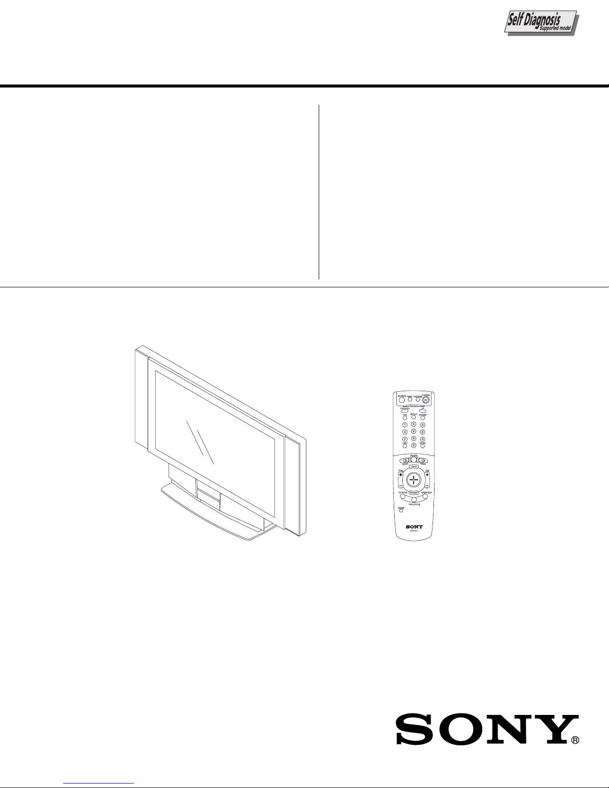
Sony KF-60DX100, RM-Y910 Service Manual
MODEL COMMANDER DEST.
–––––––– –––––––––––––– ––––––
LA-1SERVICE MANUAL
CHASSIS
KF-60DX100
KF-60DX100
RM-Y910
RM-Y910
US
Canadian
KF-60DX100 RM-Y910
LCD PROJECTION TV
– 16 –
KF-60DX100
RM-Y910
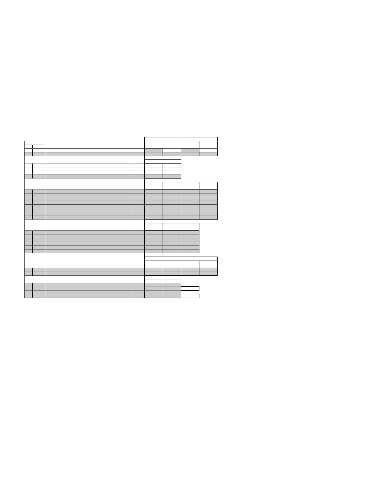
3-1. ELECTRICAL ADJUSTMENT BY REMOTE
COMMANDER
By using remote commander (RM-Y910), all circuit adjustments can be made.
NOTE : Test Equipment Required.
1. Pattern Generator (with component outputs)
2. Oscilloscope
3. Digital multimeter
3-1-1.Method of Setting the Service Adjustment
Mode
1. Standby mode. (Power off)
2. DISPLAY t 5 t VOL (+) t TV POWER
on the remote commander.
(Press each button within a second.)
The following service screen will appear.
SECTION 3
ELECTRICAL ADJUSTMENTS
Category Name
Item Name Input Signal
Mode
Item No.
3D-COMB 0 0 SERVICE
NRMD TV
WSL: xxx
F/A FLAG: xxxxxxxx
CBA FLAG: xxxxxxxx
Data
Category Name
Item Name
Item No.
L001OUT 0 0 G
OCKPN
TEMP 42DEG
LCD PJ ENGINE VER.0.026
9/11
EE2F
Data
<LCD PROJECTOR ENGINE>
3-1-2.Service Mode Adjustment
1. The SCREEN displays the item being adjusted.
2. Press “1” or “4” on the remote commander to select the
adjustment item.
3. Press “3” or “6” on the remote commander to change the data.
4. Press “2” or “5” on the remote commander to select the category.
Every time you press “2” (Category up), Service mode
changes in the order as shown below.
* : LCD Projector Engine
3D-COMB
MCP-ADJ3
MID1
* L001AOI
CCD
OP
* D-GM TG
ID
2103-1
VID ADJ
MID2
* L001POS S
* L001OUT
* D-GM IM
2103-2
USER STD
* HV POS AD
MID3
* L001SCALE
* H POS SHI
P-BOOST1
MCP-FIX
MID5
* L001ENH
* SH SET
* PLL-C
* L001Y
P-BOOST2
2151
MID6
* LCD-DR
* D-GM WB
* L001IN
P-BOOST3
AP
OSD
* LM75
* D-GM TEST
TRUS
* L001OPT
MCP-ADJ1
SNNR
* OSD-E
* D-GM TPN
DLBY
* L001OACT
ID1
* OPTION-E
MCP-ADJ2
* D-GM CUR
5. If you want to recover the latest values press “-” then
“[ENTER]” to read the memory.
6. Press “[MUTING]” then “[ENTER]” to write into memory.
7. Turn power off.
Note: Press “8” then “[ENTER]” on the remote commander to
set the shipping conditions or turn set off and on to exit.
3-1-3. Memory Write Confirmation Method
1. After adjustment, turn power off with the remote commander.
2. Turn power on and set to service mode.
3. Call the adjusted items again and confirm they were adjusted.
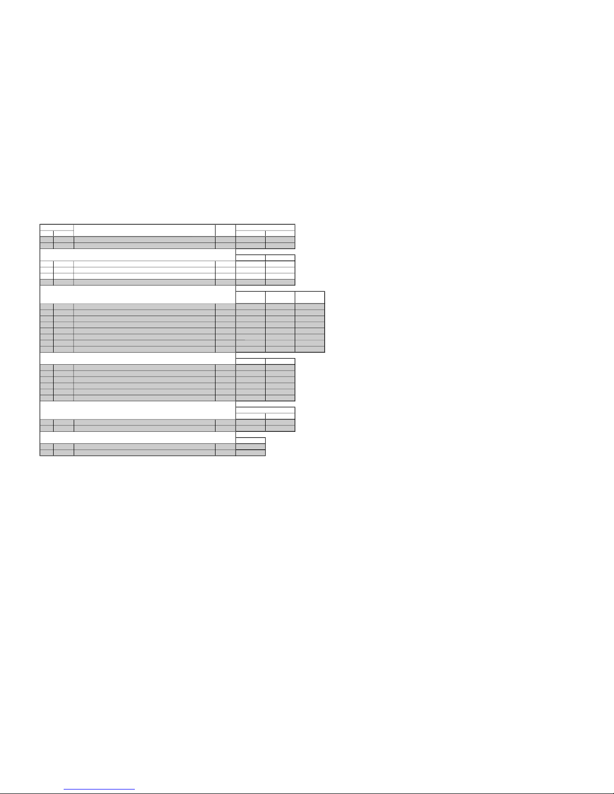
– 17 –
KF-60DX100
RM-Y910
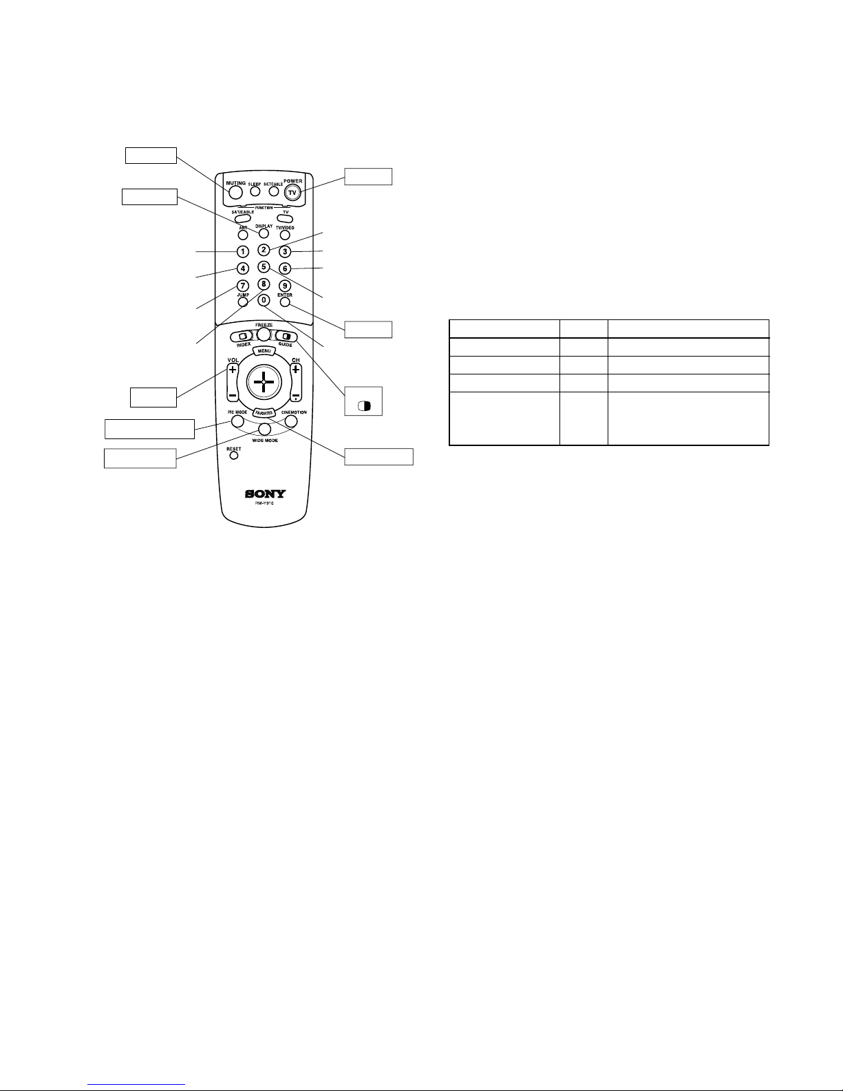
DISPLAY
Adjustment item
up
Adjustment item
down
Adjustment category
up
Read data from
NVM
Write data to NVM
POWER
MUTING
VOL +
ENTER
FAVORITES
TWIN
Adjustment category
down
Data up
Data down
PICTURE MODE
WIDE MODE
Initialize data
(Not stored)
User control goes
to the standerd state
(Shipping Conditions)
RM-Y910
3-1-4. Adjusting Buttons and Indicator
Commander Function
Button Mode Description
[MUTING] + [ENTER] WRITE Writes data to NVM.
- + [ENTER] READ Reads data from NVM.
8 + [ENTER] RESET Set the shipping condition.
7 + [ENTER] INT– Service data initialization.
Not stored.
(Be sure not to use usually)
FUNCTION OF KEYS ON COMMANDER
• 1 : Changes adjustment item. (item No. moves up)
• 4 : Changes adjustment item. (item No. moves down)
• 2 : Changes adjustment category.
(category moves up)
• 5 : Changes adjustment category.
(category moves down)
• 3 : Changes data value. (up)
• 6 : Changes data value. (down)
– 18 –
KF-60DX100
RM-Y910
3-1-5.Service Mode List
3D-COMB
Table 1
No. Name
0 NRMD Noise reduction mode setting 0 - 3 Table 1
1 YAPS Y output correction 0 - 3 3
3D (COMB)
3L (THROUGH)
3L (ROUND)
3L (THROUGH) COMB/ROUND
THROUGH ROUND THROUGH
2 CLKS System clock setting 0 - 3 1
28NR=01010101
3 NSDS Selection for standard/non-standard signal processing 0 - 3 Table 1 3 (when OP=0)
4 MSS Selection for inter-frame/inter-line processing 0 - 3 0 2 (when OP=1)
5 KILS Killer processing selection 0 - 3 2 3 NSDS 03030303
6 CDL C-signal phase with respect to the Y-signal 0 - 7 Table 5
7 DYCO DY detection coring level (Y motion detection coring) 0 - 15 Table 2
8 DYGA DY detection gain (Y motion detection gain) 0 - 15 Table 2
Table 2
9 DCCO DC detection coring level (C motion detection coring) 0 - 15 Table 2
3DYC 2DYC + YCNR MNNR YCNR
10 DCGA DC detection gain (C motion detection gain) 0 - 15 Table 2
0 NRMD= 0123
11 YNRL Frame recursive YNR nonlinear filter limit level 0 - 3 1 7 DYCO 2224
12 CNRL Frame recursive CNR nonlinear filter limit level 0 - 3 1 8 DYGA 10 10 10 10
13 VTRH Hysteresis for H sync non-standard signal detection 0 - 3 Table 3 9 DCCO 5535
14 VTRR Sensitivity for H sync non-standard signal detection 0 - 3 Table 3 10 DCGA 5 5 10 5
15 LDSR Sensitivity for frame non-standard signal detection 0 - 3 Table 3 25 D2GA 4444
16 VAPG V aperture compensation gain 0 - 7 Table 6
17 VAPI V aperture compensation convergence point 0 - 31 Table 6
18 YPFT Y peaking filter (BPF) center frequency 0 - 3 3
Table 3
19 YPFG Y peaking filter (BPF) gain 0 - 15 7
RF Video (CV/S) Component
20 YHCO Y output high frequency component coring 0 - 3 0 13 VTRH 1 1 1
21 YHCG Y output high frequency component coring gain 0 - 1 0 14 VTRR 1 1 1
22 HSSL H sync slice level 0 - 15 12 15 LDSR 2 2 2
23 VSSL V sync slice level 0 - 15 8 35 CC3N 0 0 0
24 ADCL ADC clock delay 0 - 3 3
25 D2GA Moving detection gain 0 - 7 Table 2
26 KILR Killer detection reference 0 - 15 3
Table 4
27 OP Option : Selection of comb filter & recursive noise reduction types 0 - 1 1
RF
Video (1,2,3,4)
Video (5,6)
28 NR1 Noise reduction on/off 0 - 1 Table 1 41 LIND 0 0 2
29 NR2 SNNR control on/off 0 - 1 0
30 WSL Noise level detection level data 0 - 255 Read
31 HPLL H PLL filter 0 - 1 1
Table 5
32 BPLL Burst PLL filter 0 - 1 1
RF Video (CV/S)
33 FSCF Burst extraction gain 0 - 1 0 6 CDL 3 3
34 PLLF PLL loop gain 0 - 1 1
35 CC3N Selection if a line comb filter C separation filter characteristic 0 - 1 Table 3
36 HDP Fine adjustment of the system H phase 0 - 7 5
Table 6
37 BGPS Burst gate start 0 - 15 4
VIVID STANDARD MOVIE MILD
38 BGPW Burst gate width 0 - 15 10 16 VAPG 0330
39 TEST Test bit (0 : Normal mode, 1 : Test mode) (*forbidden setting) 0 - 1 0 17 VAPI 6 10 10 4
40 WSC Amount of noise detection coring 0 - 3 1
41 LIND DRC-M line doubling setting for non-standard signal UHF/VHF & Video 1-4 0 - 15 Table 4
42 PFGO YPFG offset at GR on (*not used) 0 - 7 3
Data
Range
Data
Item
Function
2330 NRMD 0011
RF/Video S Video
Non-standard Standard Non-standardStandard
Note: • shaded items are fixed. There is no need to change data. Others are different a little
in the sets individually. Basically, there is no need to change data, too.
– 19 –
KF-60DX100
RM-Y910
2103-1
One screen (Mild) Others
No. Name
0 YLEV Y out gain 0 - 63 45 50 28 33
1 CLEV Cb & Cr out gain 0 - 63 35 58 13 31
RF Video
2 SCON Sub contrast 0 - 15 8 9
3 SCOL Sub color 0 - 15 6 7
4 SHUE Sub hue 0 - 15 9 8
5 YDLY Y/C delay time 0 - 3 0 0
6 SHAP Sharpness 0 - 15 5665
7 SHF0 Sharpness f0 selector 0 - 31222
8 PREO Shapeness pre/over-shoot ratio 0 - 30330
9 BPF0 Chroma band filter f0 setting 0 - 33000
10 BPFQ Chroma band filter Q setting 0 - 30000
11 BPSW Chroma band filter on/off 0 - 11000
12 TRAP Y block chroma trap filter on/off 0 - 10000
13 LPF Y/Cb/Cr output LPF on/off 0 - 11111
14 AFCG AFC loop gain (PLL between H sync & H VCO) 0 - 1 1 0 0
15 CDMD V countdown system mode selector 0 - 3333
16 SSMD H & V sync slide level setting 0 - 3 0 0 0
17 HMSK Masking of macrovision signal on/off 0 - 1 1 1 1
18 HALI H automatic adjustment on/off 0 - 1 0 0 0
19 PPHA H TIM phase adjustment video 0 - 15 6 8 8
One screen (Mild) Others
20 CBOF Cb/EXT Cb offset 0 - 63 32 34 36 36
21 CROF Cr/EXT Cr offset 0 - 63 32 31 33 33
One screen
Others
03
Movie
02
Movie
Component
(480i)
RF Video
Component
(480i)
RF/Video
Component
(480i)
RF/Video
Component
(480i)
RF/Video
Component
(480i)
RF
Composite
Video
S Video
Component
(480i)
Item
Function
Data
Range
RF/Video
0
23 DCTR DC transmission ratio 0 - 3
0
22 ATPD Auto-pedestal inflection point 0 - 3
– 20 –
KF-60DX100
RM-Y910
2103-2
RF/Video
No. Name VDO DRC
0 YLEV Y out gain 0 - 63 26 22
1 CLEV Cb & Cr out gain 0 - 63 23 16
RF Video
2 SCON Sub contrast 0 - 15 8 12
3 SCOL Sub color 0 - 15 6 6
4 SHUE Sub hue 0 - 15 9 8
5 YDLY Y/C delay time 0 - 3 0 0
6 SHAP Sharpness 0 - 15 6 6 6
7 SHF0 Sharpness f0 selector 0 - 3 1 1 1
8 PREO Shapeness pre/over-shoot ratio 0 - 3 0 3 3
9 BPF0 Chroma band filter f0 setting 0 - 3 0 0 0
10 BPFQ Chroma band filter Q setting 0 - 3 0 0 0
11 BPSW Chroma band filter on/off 0 - 1 0 0 0
12 TRAP Y block chroma trap filter on/off 0 - 1 0 0 0
13 LPF Y/Cb/Cr output LPF on/off 0 - 1 1 1 1
RF Video
14 AFCG AFC loop gain (PLL between H sync & H VCO) 0 - 1 1 0
15 CDMD V countdown system mode selector 0 - 3 3 3
16 SSMD H & V sync slide level setting 0 - 3 0 0
17 HMSK Masking of macrovision signal on/off 0 - 1 1 1
18 HALI H automatic adjustment on/off 0 - 1 0 0
19 PPHA H TIM phase adjustment video 0 - 15 7 8
RF/Video
VDO DRC
20 CBOF Cb/EXT Cb offset 0 - 63 32 36
21 CROF Cr/EXT Cr offset 0 - 63 33 34
Data
22 ATPD Auto-pedestal inflection point 0 - 3 *1
23 DCTR DC transmission ratio 0 - 3 *1 *1 The same data as 2103-1.
Composite
Video
S Video
Item
Function
Data
Range
RF
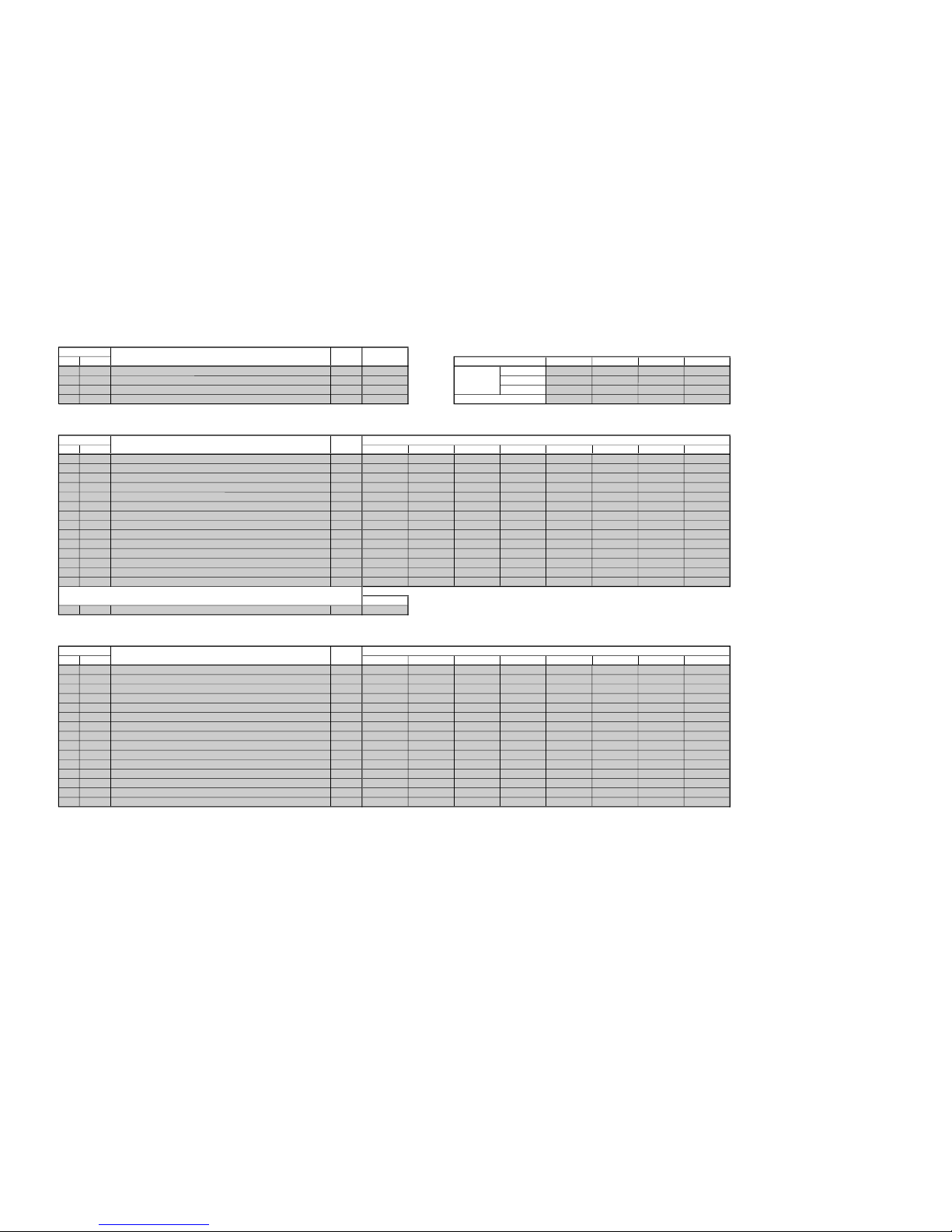
– 21 –
KF-60DX100
RM-Y910
P- BOOST 1
Table1
No. Name Vivid Standard Movie Mlid
0 BSET 0 - 7 Table1 RF 2464
1 AMS Amplitude mode selection
Data table selection
0 - 11 Video5767
2 DEMO
Demonstration mode on/off
0 - 1 0 Component 1363
3 SN Steepness correction 0 - 63- 0000
P- BOOST 2
No. Name 01234567
0 LWID Line width correction 0 - 630 31313131313131
1 STEP 0 - 6300000000
2 CRNG Coring level
Steeness correction
0 - 630 1525103015 515
3 VDC Video dependent coring on/off 0 - 101111111
4 OSP Overrrule smart peaking 0 - 100100000
5 BOST Black offset compensation on/off 0 - 100000000
6 ABST Adaptive black stretch 0 - 6300000000
7 VGAM Variable gamma 0 - 63 32 28 24 24 22 27 31 22
8 NLMP Non-linearity amplifier 0 - 630 2220211522 718
9 PKNG Peaking amplitude 0 - 630 37153225352042
10 CFS Contour filter selection 0 - 101111111
11 FHS Line frequency selection 0 - 100000000
12 LDH Luminance determined histogram
Snow color adjustment by green stretch
0 - 101111111
13 SNOW 0 - 111111111
Comon
14 WLB Window letterbox format 0 - 1 0
P- BOOST 3
No. Name 01234567
0 CDS Color dependent sharpness on/off 0 - 111111111
1 CTI Color transient improvement on/off 0 - 100000000
2 WPO White-point stretch on/off 0 - 111111111
3 DBL Blue stretch on/off 0 - 100000000
4GBLBlue stretch gain 0 - 100000000
5 SBL Blue stretch size 0 - 100000000
6 DSK Dynamic skin tone on/off 0 - 100000000
7 ASK Dynamic skin tone angle 0 - 100000000
8 WSK Dynamic skin tone width 0 - 100000000
9 SSK Dynamic skin tone size 0 - 100000000
10 DGR Green enhancement on/off 0 - 101100100
11 GGR Green enhancement gain 0 - 100000000
12 WGR Green enhancement width 0 - 100000000
13 SGR Green enhancement size 0 - 100000000
14 CDLY Chrominance delay 0 - 747777454
BSET data (P-BOOST1 _0_BSET= )
Two screen
SCREEN MODE
Data
One screen
Item
Function
Data
Range
BSET data (P-BOOST1 _0_BSET= )
Item
Function
Data
Range
Item
Function
Data
Range
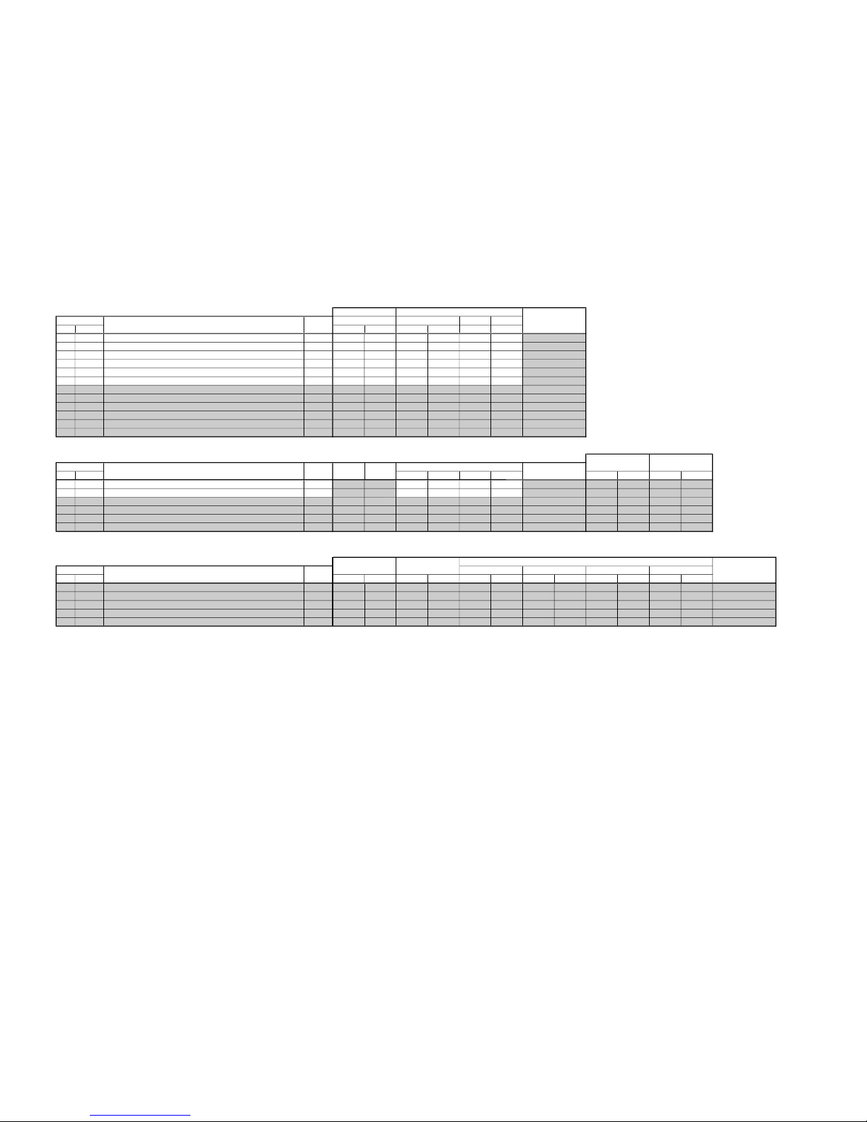
– 22 –
KF-60DX100
RM-Y910
RF / Video Component
480i 480i 480p/720p 1080i
No. Name Mild Others Mild Others All mode All mode
0 RDRV RED drive gain control 0 - 63 50 50 50 50 50 50
1 RCUT
RED cutoff control
0 - 63 40 40 40 40 40 40
2 GDRV
GREEN drive gain control
0 - 63 50 50 50 50 50 50
3 GCUT
GREEN cutoff control
0 - 63 40 40 40 40 40 40
4 BDRV
BLUE drive control
0 - 63 50 50 50 50 50 50
5 BCUT
BLUE cutoff control
0 - 63 40 40 40 40 40 40
6 CROF
DC offset for Cr signal
0 - 15999967
7 CBOF
DC offset for Cb signal
0 - 15777767
8 SCON
Sub contrast gain control
0 - 15444455
9 SBRT
Sub brightness control
0 - 63 31 31 31 31 31 31
10 PICT
Picture gain control
0 - 63 53 53 50 50 50 50
11 BRT
Brightness control
0 - 63 55 55 55 55 55 55
Component
No. Name 480i 480p 720p 1080i Neutral Warm Neutral Warm
0 SCOL Color gain control 0 - 15777877 ---1 SHUE Hue center control 0 - 15888887 ---2 RYR
Sets +(R-Y) component in R-Y axes
0 - 15222244 0
000
3 RYB
Sets -(B-Y) component in R-Y axes
0 - 15 10 10 10 10 12 12
+4 +4 0 0
4 GYR
Sets -(R-Y) component in G-Y axes
0 - 15 10 10 10 12 10 10
0000
5 GYB
Sets -(B-Y) component in G-Y axes
0 - 15888555
0000
MCP-ADJ3
No. Name Mild Others Mild Others Mild Others Mild Others Mild Others Mild Others
0 SSHP Sharpness center control 0 - 3110000010100
1F0
Sets sharpness f0
0 - 3131313133333
2 POVR
Sets the preshoot to overshoot ratio
0 - 3131322222222
3 SYSM
Sets signal bandwidth
0 - 3111112111122
4 CTI Sets edge improvement of color difference signal 0 - 3000001010001
Shift value of HD
system
7
4
31
Twin , Favorite, Index,
Freeze
53
55
Video
Item
Function RF
Twin , Favorite, Index,
Freeze
VideoRF
480i 480p
Item
Function
Data
Range
Item
Function
Data
Range
Data
Range
40
50
40
9
Twin , Favorite, Index,
Freeze
50
40
50
0
10
8
7
9
2
10
720p 1080i
Component
3
0
2
1
MCP-ADJ1
MCP-ADJ2
 Loading...