

Page 1
Digital Wireless
Receiver
4-426-168-11 (1)
The supplied CD-ROM includes the Operating Instructions for the DWR-S02D
digital wireless receiver (English, French, German, Italian, Spanish, and
Japanese versions) and the frequency lists (English and Japanese versions)
in PDF format.
For more details, see “Using the CD-ROM Manual” on page 9.
Operating Instructions
Before operating the unit, please read this manual thoroughly
and retain it for future reference.
DWR-S02D
© 2008 Sony Corporation
F
Page 2

For the customers in the U.S.A.
This equipment has been tested and found
to comply with the limits for a Class B
digital device, pursuant to Part 15 of the
FCC Rules. These limits are designed to
provide reasonable protection against
harmful interference in a residential
installation. This equipment generates,
uses, and can radiate radio frequency
energy and, if not installed and used in
accordance with the instructions, may cause
harmful interference to radio
communications. However, there is no
guarantee that interference will not occur in
a particular installation. If this equipment
does cause harmful interference to radio or
television reception, which can be
determined by turning the equipment off
and on, the user is encouraged to try to
correct the interference by one or more of
the following measures:
- Reorient or relocate the receiving
antenna.
- Increase the separation between the
equipment and receiver.
- Connect the equipment into an outlet on
a circuit different from that to which the
receiver isconnected.
- Consult the dealer or an experienced
radio/TV technician for help.
You are cautioned that any changes or
modifications not expressly approved in
this manual could void your authority to
operate this equipment.
All interface cables used to connect
peripherals must be shielded in order to
comply with the limits for a digital device
pursuant to Subpart B of Part 15 of FCC
Rules.
If you have any questions about this
product, you may call;
Sony Customer Information Service Center
1-800-222-7669 or
http://www.sony.com/
Declaration of Conformity
Trade Name: SONY
Model: DWR-S02D
Responsible Party: Sony Electronics
Inc.
Address: 16530 Via Esprillo, San
Diego, CA 92127 U.S.A.
Telephone Number: 858-942-2230
This device complies with part 15 of the
FCC Rules. Operation is subject to the
following two conditions: (1) this device
may not cause harmful interference,
and (2) this device must accept any
interference received, including
interference that may cause undesired
operation.
For the customers in Canada
This Class B digital apparatus complies
with Canadian ICES-003.
Operation is subject to the following two
conditions: (1) this device may not cause
interference, and (2) this device must accept
any interference, including interference that
may cause undesired operation of the
device.
The term “IC” before the radio certification
number only signifies that Industry Canada
technical specifications were met.
Use of Sony wireless devices is regulated
by the Industry Canada as described in their
Radio Standard Specification RSS-123.
A licence is normally required. The local
district office of Industry Canada should
therefore be contacted. When the operation
of the device is within the broadcast band,
the licence is issued on no-interference, noprotection basis with respect to broadcast
signals.
Pour les utilisateurs au Canada
Cet appareil numérique de la classe B est
conforme à la norme NMB-003 du Canada.
L’utilisation doit répondre aux deux
conditions suivantes : (1) ce matériel ne doit
pas provoquer de brouillage et (2) il doit
2
Page 3
accepter tout brouillage, même celui qui est
susceptible d’affecter son fonctionnement.
La mention « IC: » devant le numéro de
certification/ homologation signifie
uniquement que les spécifications
techniques d’Industrie Canada sont
remplies.
L’usage des appareils sans fil Sony est
réglementé par l’Industrie Canada comme
décrit dans leur Cahier des Normes
Radioélectriques CNR-123.
Une licence est normalement requise.
Le bureau de l’Industrie Canada doit être
contacté. Lorsque le fonctionnement de
l’appareil respecte les limites de la bande de
radiodiffusion, la licence est accordée sur la
base d’une non-interférence, nonprotection pour les signaux de
radiodiffusion.
This model has an RF module of the
FCC/IC approval built-in.
BUILT IN MODULE RM-215
FCC ID: AK8RM215
IC: 409B-RM215
Ce modèle dispose d’un module à
radiofréquence (RF) intégré qui a été
certifié par la FCC/IC.
MODULE INTÉGRÉ RM-215
ID FCC : AK8RM215
IC : 409B-RM215
For the customers in the U.S.A.
You are cautioned that any changes or
modifications not expressly approved in
this manual could void your authority to
operate this equipment.
IMPORTANT NOTE: To comply with the
FCC RF exposure compliance
requirements, no change to the antenna or
the device is permitted,
Any change to the antenna or the device
could result in the device exceeding the RF
exposure requirements and void user’s
authority to operate this device.
This device complies with FCC radiation
exposure limits set forth for uncontrolled
equipment and meets the FCC radio
frequency (RF) Exposure Guidelines in
Supplement C to OET65. This device has
very low levels of RF energy that it is
deemed to comply without testing of
specific absorption radio (SAR).
For the customers in Canada
Operation is subject to the following two
conditions: (1) this device may not cause
interference, and (2) this device must accept
any interference, including interference that
may cause undesired operation of the
device.
The term “IC” before the radio certification
number only signifies that Industry Canada
technical specifications were met.
Pour les utilisateurs au Canada
L’utilisation doit répondre aux deux
conditions suivantes : (1) ce matériel ne doit
pas provoquer de brouillage et (2) il doit
accepter tout brouillage, même celui qui est
susceptible d’affecter son fonctionnement.
La mention « IC: » devant le numéro de
certification/ homologation signifie
uniquement que les spécifications
techniques d’Industrie Canada sont
remplies.
This device complies with part 15 of the
FCC Rules. Operation is subject to the
following two conditions: (1) this device
may not cause harmful interference, and (2)
this device must accept any interference
received, including interference that may
cause undesired operation.
For the customers in Europe
Hereby, Sony Corporation, declares that
this DWR-S02D is in compliance with the
essential requirements and other relevant
3
Page 4

provisions of the Directive 1999/5/EC.
For details, please access the following
URL: http://www.compliance.sony.de/
Pour les clients en Europe
Par la présente Sony Corporation déclare
que l'appareil DWR-S02D est conforme
aux exigences essentielles et aux autres
dispositions pertinentes de la directive
1999/5/CE.
Pour toute information complémentaire,
veuillez consulter l’URL suivante:
http://www.compliance.sony.de/
Für Kunden in Europa
Hiermit erklärt Sony Corporation, dass sich
das Gerät DWR-S02D in Übereinstimmung
mit den grundlegenden Anforderungen und
den übrigen einschlägigen Bestimmungen
der Richtlinie 1999/5/EG befindet.
Weitere Informationen erhältlich unter:
http://www.compliance.sony.de/
Per i clienti in Europa
Con la presente Sony Corporation dichiara
che questo DWR-S02D è conforme ai
requisiti essenziali ed alle altre disposizioni
pertinenti stabilite dalla direttiva 1999/5/
CE.
Per ulteriori dettagli, si prega di consultare
il seguente URL:
http://www.compliance.sony.de/
Para los clientes de Europa
Por medio de la presente Sony Corporation
declara que el DWR-S02D cumple con los
requisitos esenciales y cualesquiera otras
disposiciones aplicables o exigibles de la
Directiva 1999/5/CE.
Para mayor información, por favor consulte
el siguiente URL:
http://www.compliance.sony.de/
Voor de klanten in Europa
Hierbij verklaart Sony Corporation dat het
toestel DWR-S02D in overeenstemming is
met de essentiële eisen en de andere
relevante bepalingen van richtlijn 1999/5/
EG.
Nadere informatie kunt u vinden op:
http://www.compliance.sony.de/
For kunder i Europa
Härmed intygar Sony Corporation att denna
DWR-S02D står I överensstämmelse med
de väsentliga egenskapskrav och övriga
relevanta bestämmelser som framgår av
direktiv 1999/5/EG.
För ytterligare information gå in på följande
hemsida: http://www.compliance.sony.de/
Para os clientes da Europa
Sony Corporation declara que este DWRS02D está conforme com os requisitos
essenciais e outras disposições da Directiva
1999/5/CE.
Para mais informacoes, por favor consulte a
seguinte URL:
http://www.compliance.sony.de/
For kunder i Europa
Undertegnede Sony Corporation erklærer
herved, at følgende udstyr DWR-S02D
overholder de væsentlige krav og øvrige
relevante krav i direktiv 1999/5/EF.
For yderligere information gå ind på
følgende hjemmeside:
http://www.compliance.sony.de/
Euroopassa oleville asiakkaille
Sony Corporation vakuuttaa täten että
DWR-S02D tyyppinen laite on direktiivin
1999/5/EY oleellisten vaatimusten ja sitä
koskevien direktiivin muiden ehtojen
mukainen.
Halutessasi lisätietoja, käy osoitteessa:
http://www.compliance.sony.de/
For kundene i Europa
Sony Corporation erklærer herved at
utstyret DWR-S02D er i samsvar med de
grunnleggende krav og øvrige relevante
krav i direktiv 1999/5/EF.
For flere detaljer, vennligst se:
http://www.compliance.sony.de/
Για τους πελάτες στην Eυρώπη
Με την παρούσα η Sony Corporation
δηλώνει τι DWR-S02D
συμμορφώνεται προς της ουσιώδεις
απαιτήσεις και τις λοιπές σχετικές
διατάξεις της οδηγίας 1999/5/ΕΚ..
4
Page 5
Για λεπτομέρειες παρακαλούμε
πως ελένξετε την ακλουθη
σελίδα του διαδικτύου:
http://www.compliance.sony.de/
Pro zákazníky v Evropě
Sony Corporation tímto prohlašuje, že
tento DWR-S02D je ve shodě se
základními požadavky a dalšími
příslušnými ustanoveními směrnice
1999/5/ES.
Podrobnosti lze získat na následující
URL:
http://www.compliance.sony.de/
Euroopa klientidele
Sony Corporation kinnitab käesolevaga
seadme DWR-S02D vastavust 1999/5/EÜ
direktiivi põhinõuetele ja nimetatud
direktiivist tulenevatele teistele
asjakohastele sätetele.
Üksikasjalikum info:
http://www.compliance.sony.de/.
Európai vásárlóink fi gyelmébe
Alulírott, Sony Corporation
nyilatkozom, hogy a(z) DWR-S02D
megfelel a vonatkozó alapvető
követelményeknek és az 1999/5/EC
irányelv egyéb előírásainak.
További információkat a következő
weboldalon találhat:
http://www.compliance.sony.de/
Dotyczy klientów z Europy
Niniejszym Sony Corporation
oświadcza, że DWR-S02D jest zgodne z
zasadniczymi wymaganiami oraz innymi
stosownymi postanowieniami
Dyrektywy 1999/5/WE.
Szczegółowe informacje znaleźć można
pod następującym adresem URL:
http://www.compliance.sony.de/
Pentru clienţii din Europa
Prin prezenta, Sony Corporation declară
că acest DWR-S02D respectă cerinţele
esenţiale și este în conformitate cu
prevederile Directivei 1995/5/EC.
Pentru detalii, vă rugăm accesaţi
următoarea adresă:
http://www.compliance.sony.de/
Pre zákazníkov v Európe
Sony Corporation týmto vyhlasuje, že
DWR-S02D spĺňa základné požiadavky
a všetky príslušné ustanovenia Smernice
1999/5/ES.
Podrobnosti získate na nasledovnej
webovej adrese:
http://www.compliance.sony.de/
Za stranke v Evropi
Sony Corporation izjavlja, da je ta
DWR-S02D v skladu z bistvenimi
zahtevami in ostalimi relevantnimi
določili direktive 1999/5/ES.
Za podrobnosti vas naprošamo, če
pogledate naURL:
http://www.compliance.sony.de/
5
Page 6

Table of Contents
Features .......................................... 8
Using the CD-ROM Manual ......... 9
Preparations ............................. 9
Reading the CD-ROM
Manual ..................................... 9
Parts Identification ...................... 10
Preparation .................................. 12
Attaching to a Camcorder ...... 12
Using the DWA-01D/F01D
Wireless Adapter ................... 13
Setting the Receiving Channel ... 13
Selecting the Frequency Band /
Group / Channel .................... 13
Using the Active Channel Scan
Function ................................. 14
Using the Clear Channel Scan
Function ................................. 15
Using the Encrypted Transmission
Function ........................................ 16
Using Secure Key Mode
(SECURE KEY) .................... 16
Using Password Mode
(PASSWORD) ....................... 17
Using a USB Keyboard ............... 18
Menu Displays and Detailed
Settings ......................................... 19
Menu Structure and
Hierarchy ............................... 19
Basic Menu Operations ......... 20
UTILITY Menu ........................... 20
Selecting the AES/EBU Output
Reference Level (AES/EBU
LVL@MIC) ........................... 20
Selecting the Sync Signal
(SYNC SOURCE) ................. 21
Terminating the Sync Signal
(WORD SYNC 75ohm) ........ 21
Selecting Output 1 (ANALOG
OUTPUT1) .............................21
Showing the Accumulated Use
Time (TIME) ..........................21
Setting the Brightness of the
Display (BRIGHTNESS) .......22
Automatic Dimming of the
Display (DIMMER MODE) ..22
Resetting Parameters to their
Factory Settings (FACTORY
PRESET) ................................22
Displaying the Software Version
(VERSION) ............................22
RX (tuner) 1/2 Menu ....................23
Frequency Band Selection
(BAND) ..................................23
Group/Channel (GP/CH)
Selection .................................23
Active Channel Scanning
Function (ACT CH SCAN) ....23
Clear Channel Scan Function
(CLR CH SCAN) ...................23
Using the RF Squelch Function
(RF SQUELCH) .....................23
Encrypted Transmission
Function (ENCRYPTION) ....23
Display of the Audio Signal
Delay Time (SYSTEM
DELAY) .................................24
TX (Transmitter Virtual) 1/2
Menu ..............................................24
Display of the Transmitter’s
Name (NAME) .......................25
Display of the Transmission
Power Setting (RF
POWER) ................................25
Table of Contents
6
Page 7

Display of Audio Input Level
(INPUT LEVEL) ................... 25
Display of the Low-cut Filter
Setting (LCF) ......................... 25
Display of the Power Save
Setting (POWER SAVE) ....... 25
Display of Accumulated Battery
Use Time (TIME) .................. 25
Display of the +48V Power
Setting (+48V) ....................... 25
Wireless Remote Control
Function (RF REMOTE) ....... 25
Using the Cross Remote
Function ........................................ 26
Pairing with a Transmitter ..... 26
Changing the Settings on the
Transmitter .................................. 28
Frequency Band Setting
(BAND) ................................. 28
Group/Channel Setting (GP/
CH) ........................................ 28
Transmission Power Setting
(RF POWER) ........................ 29
Audio Input Level Setting
(INPUT LEVEL) ................... 29
Low-cut Filter Setting
(LCF) ..................................... 29
Power-saving Setting (POWER
SAVE) ................................... 29
+48V Power Setting
(+48V) ................................... 29
Cross Remote Function Setting
(RF REMOTE) ...................... 29
Block Diagram ............................. 30
Troubleshooting........................... 31
Important Notes on Operation ... 33
Notes on Using the
Receiver .................................33
On Cleaning ........................... 33
Specifications ............................... 34
Carrier Frequencies and Channel
Steps.............................................. 36
Table of Contents
7
Page 8

Features
It enables highly secure transmission with
high sound quality and low system latency,
and supports simultaneous multi-channel
operation.
The DWR-S02D digital wireless receiver is
a slot-in type wireless receiver capable of
receiving two channels from digital
wireless transmitters. Used in conjunction
with Sony professional camcorders or the
optional DWA-01D/F01D wireless adapter,
the DWR-S02D enables the construction of
a fully digital ENG/EFP audio system.
This receiver enables the application of
multiple channels over unused television
channels through the use of the built-in
Sony original channel plan.
What is DWX?
DWX refers to Sony’s new digital wireless
microphone system. The DWX series
reflects Sony’s extensive expertise in
professional microphones and sound
design. It represents a successful blend of
Sony know-how, wireless technology
renowned for stability, and cutting-edge
digital audio technology.
In addition to realizing the high sound
quality possible with a digital system, the
DWX series supports multi-channel
simultaneous operation, encrypted
transmission, and metadata transmission for
monitoring the status of multiple
transmitters. Using a main link and a
separate additional link, remote control of
transmitters from the receiver is also
possible. With its many advanced features,
the system has the potential to revolutionize
the workflow of professional applications.
What is WiDIF-HP?
WiDIF-HP (WiDIF: Wireless Digital
Interface Format, HP: High Profile) is a
wireless digital audio interface format
developed by Sony.
What is Cross Remote?
Cross Remote is a system that allows
transmitters to be monitored and controlled
from a receiver and the Wireless Studio
control software installed on a computer
connected to the receiver.
For example, the settings of a transmitter
worn under clothing can be easily changed
over the wireless link.
Preprogrammed wireless
channel plans for
simultaneous multi-channel
operation
The DWR-S02D has many preprogrammed
channel groups, meaning combination of
wireless channels to permit simultaneous
operation of multiple channels without
intermodulation.
Two-channel slot-in wireless
receiver
Despite its dual-channel receiver capability,
the DWR-S02D is small enough to be
mounted directly in the slot of the Sony
camcorder.
Rear mounting to camcorders
The DWR-S02D can be rear-mounted to a
range of Sony professional camcorders using the DWA-01D/F01D wireless
adapter. When used with a camcorder that
has AES/EBU inputs, full-digital audio
recording is also possible.
8
Features
Page 9
Auto channel scanning
function
The DWR-S02D comes with two auto
channel scanning functions that allows for
fast, easy and safe frequency channel
changes.
Compact, lightweight, and
rugged design
The DWR-S02D is highly compact and
lightweight, maintaining a good balance
even when mounted on a camcorder. In
addition, it is made of magnesium die-cast
and aluminum, making it extremely rugged
and suitable for the harsh environment.
Easy-to-see, full dot-matrix
OLED (Organic Light-Emitting
Diode) display
The quick response of the OLED display
enables real-time operating conditions to be
displayed clearly and accurately.
Using the CDROM Manual
The supplied CD-ROM includes the
Operating Instructions for the DWR-S02D
(English, French, German, Italian, Spanish,
and Japanese versions) and the frequency
lists (English and Japanese versions) in
PDF format.
Preparations
The following program must be installed on
your computer in order to read the
Operating Instructions contained on the
CD-ROM.
• Adobe Reader Version 6.0 or higher
Note
If Adobe Reader is not installed, you can
download it from the Adobe Systems Web
site.
Adobe and Adobe Reader are trademarks of
Adobe Systems Incorporated in the United States
and/or other countries.
Reading the CD-ROM Manual
To read the Operating Instructions and
frequency lists contained on the CD-ROM,
do the following.
1 Insert the CD-ROM in your CD-ROM
drive.
A cover page appears automatically in
your browser.
Using the CD-ROM Manual
9
Page 10
If it does not appear automatically in
the browser, double-click on the
index.htm file on the CD-ROM.
2 Select and click on the Operating
Instructions or the frequency lists that
you want to read.
This opens the selected PDF file.
Memo
The files may not be displayed properly,
depending on the version of Adobe Reader.
In such a case, install the latest version you
can download from the URL mentioned in
“Preparations” above.
Note
If you have lost or damaged the CD-ROM,
you can purchase a new one to replace it.
Contact your Sony service representative.
Parts Identification
Parts Identification
10
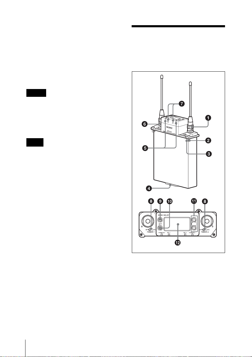
a Antenna and antenna connector
(BNC type)
Connect the supplied antenna here.
b Mounting screw
Use to attach the receiver to a camcorder or
DWA-01D/F01D wireless adapter.
c Compatibility pin
Prevents the attachment of an incompatible
camcorder or adapter.
Page 11
d Accessory connector
Use to connect the receiver to a camcorder
or DWA-01D/F01D wireless adapter.
Power, audio, and control signals are sent
through this connector.
e POWER indicator
Lights up green when the power is on.
The POWER1 and POWER2 indicators
indicate the power status of tuner 1 and
tuner 2, respectively.
f USB connector
Connecting an optional keyboard to this
connector allows menu operation to be
performed on the keyboard. Connecting the
transmitter to this connector through the
supplied USB cable allows an encryption
key to be exchanged with the transmitter.
For details on the use of a USB keyboard, see
“Using a USB Keyboard” on page 18.
For details on encryption key exchange, see “Using
the Encrypted Transmission Function” on page 16.
g RF (radio frequency) indicators
Indicate the RF input level of tuner 1 and
tuner 2.
The indicators that light up depend on the
RF squelch function setting as follows:
i MENU SELECT (menu selection)
button
Selects the displayed menu.
j SET button
Changes the item to be set or enters the
selected function or parameter value.
k + or – button
Use to select a function or value.
If you set the POWER switch on tuner 1 or
tuner 2 to ON while holding down the +
button, the tuner that you turned ON will
begin the scanning operation of the clear
channel scan function.
If you set the POWER switch on tuner 1 or
tuner 2 to ON while holding down the –
button, the tuner that you turned ON will
begin the pairing operation of the wireless
remote control function.
l Display section
Meter display
When the RF (radio frequency) squelch
level is set to OFF:
On in green: 25 dBµ or more
On in red: 15 dBµ to 25 dBµ
Off: Less than 15 dBµ
When the RF (radio frequency) squelch
level is set to 20 dBµ:
On in green: 30 dBµ or more
On in red: 20 dBµ to 30 dBµ
Off: Less than 20 dBµ
h POWER switches
Turn tuner 1 and tuner 2 on or off
individually.
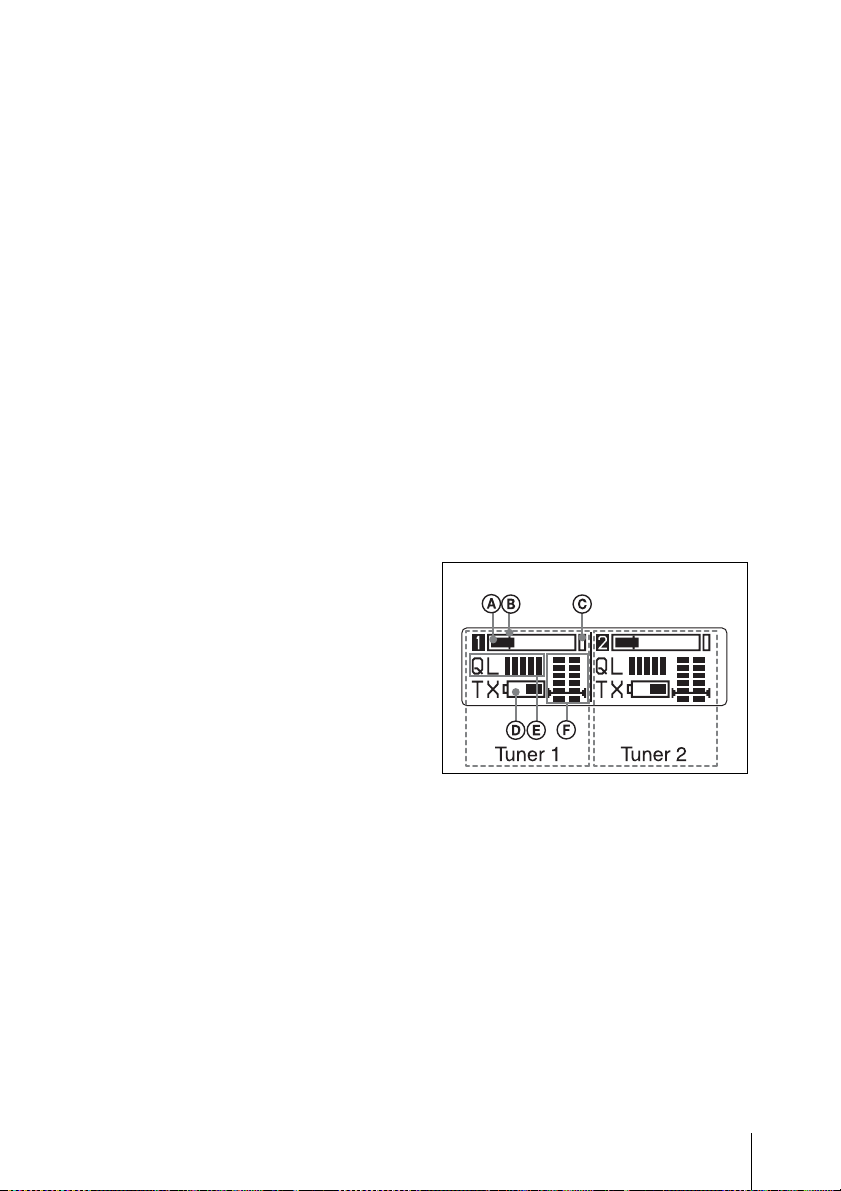
A Audio input level meter
Indicates the input signal level.
B Reference level gage
Indicates the reference input level.
–58 dBu (–60 dBV) is indicated when the
input level is set to “MIC” on the
transmitter, and +4 dBu when the input
level is set to line.
C Peak indicator
Warns of excessive input by lighting up
when the signal is 3 dB below the level at
which distortion begins.
Parts Identification
11
Page 12
D Battery indication
Based on metadata from the transmitter,
shows the transmitter’s battery condition
according to 8 level indications.
Replace both batteries when the battery
indication starts to flash.
For details on how to change the batteries on the
transmitter, refer to the operating instructions
supplied with the transmitter.
E Signal quality level meter
Indicates the quality of the RF signal
reception.
The occurrence of many data errors during
a given interval reduces the height of the bar
graph.
This meter allows you to monitor signal
deterioration that may occur when there is
noise or when the transmitter is too far from
the receiver.
F RF level meter
Indicates the RF input level. The number of
segments that light up depends on the input
level.
When the squelch function is set, the
squelch level is indicated on the RF level
meter.
When the RF input level drops below the
squelch level, the output signal is muted.
Preparation
Attaching to a Camcorder
This receiver can be inserted into a slot
provided on compatible Sony camcorders.
The audio signal, which is converted to
digital by the digital wireless transmitter,
can be recorded as is to the camcorder,
allowing you to create a fully digital
system.
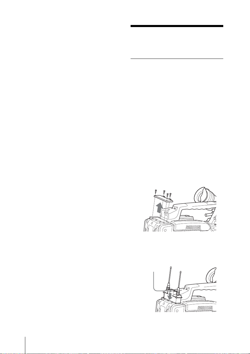
1 Remove the cover from the slot for the
wireless receiver on the camcorder,
and insert the receiver into the slot.
To avoid inserting the receiver in the
wrong direction, confirm the location
of the mounting screws and
compatibility pin before inserting the
wireless receiver.
12
2 After inserting the receiver completely
into slot, securely fasten the four
mounting screws.
Receiver
Preparation
Page 13
For details about operating the camcorder with the
receiver, refer to the operating instructions supplied
with the camcorder.
Note
If the camcorder is not compatible with the
receiver, the compatibility pin on the
receiver will make it impossible to insert
the receiver into the slot.
For details on compatible camcorders, consult a
Sony sales representative.
Using the DWA-01D/F01D Wireless Adapter
Attaching the receiver to the DWA-01D/
F01D wireless adapter allows them to be
used as a portable wireless receiver.
For details, refer to the operating instructions
supplied with the adapter.
Setting the Receiving Channel
The receiver provides groups of channels
for interference-free transmission. When
using multiple wireless microphones and
transmitters (simultaneous multi-channel
operations) within the same area, selecting
the same group and using a channel within
that group can prevent signal interference.
Selecting the Frequency Band / Group / Channel
Set the frequency band (BAND), group
(GP), and channel (CH) as follows.
For details on the groups and channels included in
each frequency band, refer to “Sony Digital
Wireless Microphone System Frequency Lists” on
the supplied CD-ROM.
For details on menu operations, see “Basic Menu
Operations” on page 20.
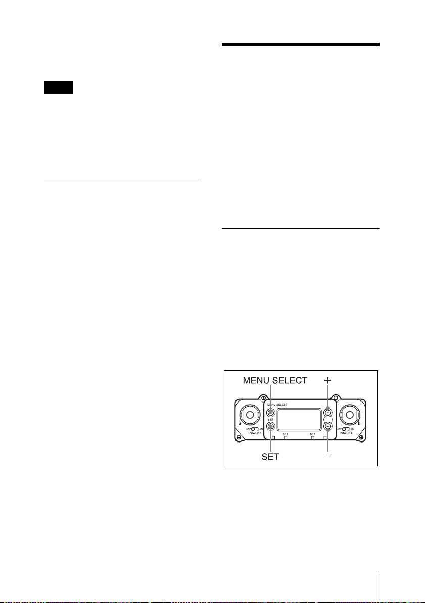
1 Press the MENU SELECT button
repeatedly until the RX1/RX2 menu is
displayed.
2 Press the + or - button repeatedly until
the BAND screen is displayed.
Setting the Receiving Channel
13
Page 14
3 Hold down the SET button until the
item to be set flashes.
4 Press the + or - button repeatedly to
select a frequency band.
5 Press the SET button to confirm the
selection.
6 Press the + or - button repeatedly until
the GP/CH screen is displayed.
7 Hold down the SET button until the
item to be set flashes.
8 Press the + or - button repeatedly to
select a group.
9 Press the SET button to confirm the
selection.
The channel indicator starts flashing.
10Press the + or - button repeatedly to
select a channel.
11Press the SET button to confirm the
selection.
About use of the same group
and channel by adjacent
systems
When the same group and channel are being
used by two or more systems that are within
sight of each other and are separated
without partitions or obstacles in wide open
place, each system should be at least 100
meters away from the others to avoid
interference.
Using the Active Channel Scan Function
This function scans for a Sony digital
wireless frequency from the frequency lists
within the GP (group) selected during the
GP/CH selection function.
Required condition for the detection:
• Sony digital wireless signal
• Above the RF squelch level of the
receiver
• The setting of the encrypted transmission
function is correct.
When the wireless remote control
function is operating:
When you change the BAND/GP/CH
setting on the receiver, you can send the
BAND/GP/CH setting to the transmitter
that is paired with the receiver.
Note
If the receiving channel (CH) configured on
the receiver is a channel for which use with
the wireless remote control function is
restricted on the transmitter side, the
UNMATCH screen appears.
In such cases, change the receiving channel
on the receiver. If you want to use the
restricted channel, set REMOTE to OFF in
the transmitter’s menu to release the
channel restriction, and manually configure
the transmitter’s channel.
Setting the Receiving Channel
14
1 Press the MENU SELECT button
repeatedly until the RX1/RX2 menu is
displayed.
2 Press the + or – button repeatedly until
the ACT CH SCAN indication is
displayed.
3 Hold down the SET button until the
item to be set flashes.
4 Press the + or – button repeatedly to
select YES.
Scanning starts. When a Sony digital
wireless frequency is detected,
scanning stops and the frequency is
displayed.
If you select NO, the scanning function
will be cancelled.
Page 15

5 If you decide on that frequency after
checking it out, press the + or
repeatedly to select SET, and then
press the SET button.
To search for another frequency, press
the + or
CONTINUE, and then press the SET
button.
Note
If a Sony digital wireless frequency within
the group is not found by the second try,
scanning is cancelled.
– button repeatedly to select
Using the Clear Channel Scan Function
This function searches for a channel that is
not being used by another wireless device
or by a TV station. This function makes it
easy to find an available channel to allow
the wireless microphone to be used without
interference.
The function searches for an empty channel
among the registered frequencies within the
GP (group) selected by the GP/CH selection
function.
In addition to using the following
procedure, you can also set the POWER
switch on tuner 1 or tuner 2 to ON while
holding down the + button to start the clear
channel scan function on the tuner that you
turned ON.
– button
1 Press the MENU SELECT button
repeatedly until the RX1/RX2 menu is
displayed.
2 Press the + or – button repeatedly until
the CLR CH SCAN indication is
displayed.
4 In the CLR CH SCAN indication,
press the + or
select YES.
Scanning starts. When an empty
channel is detected, scanning stops and
the frequency is displayed.
If you select NO, the scanning function
will be cancelled.
– button repeatedly to
5 If you decide to use that channel, press
the + or
SET, and then press the SET button.
When the wireless remote control
function is operating, the group/
channel setting can be sent to the
transmitter.
To search for another empty channel,
press the + or
select CONTINUE, and then press the
SET button.
Notes
• If an empty channel within the group is
not found by the second try, scanning is
cancelled.
• If the receiving channel (CH) configured
on the receiver is a channel for which use
with the wireless remote control function
is restricted on the transmitter side, the
UNMATCH screen appears.
In such cases, change the receiving
channel on the receiver. If you want to
use the restricted channel, set REMOTE
to OFF in the transmitter’s menu to
release the channel restriction, and
manually configure the transmitter’s
channel.
– button repeatedly to select
– button repeatedly to
3 Hold down the SET button until the
item to be set flashes.
Setting the Receiving Channel
15
Page 16

Using the Encrypted Transmission Function
The encryption key used by the transmitter
and receiver is newly generated for each
key transmission, resulting in highly secure
communication.
The encryption key used between the
transmitter and the receiver is saved when
the power is turned off, so the encrypted
transmission can be resumed the next time
the power is turned on.
This receiver is capable of receiving
scrambled signals from Sony digital
wireless transmitters. This function
prevents hacking of the signal.
To use this function, select one of the
following encrypted transmission modes:
Secure key mode: A secure key that is
automatically generated by the transmitter
is used by both the transmitter and receiver
in this one-to-one encrypted transmission
method.
Password mode: You choose a
password of up to eight characters that can
be set for multiple transmitters and
receivers. This enables encrypted
transmission to be conducted within a
group.
Note
Make sure the same mode is set on the
transmitter and receiver.
Using Secure Key Mode
(SECURE KEY)
Use this mode for one-to-one encrypted
transmission between one transmitter and
one receiver.
An encryption key that cannot be read from
the outside is automatically generated by
the transmitter. This key is transmitted to
the receiver through a USB connection or
the RF REMOTE function, enabling
encrypted transmission to take place.
1 Preparing the receiver (this unit)
1 With the ENCRYPTION
indication on (in the RX1/2 menu),
hold down the SET button until the
item to be set flashes.
2 Press the + or
to select SECURE KEY, and then
press the SET button.
– button repeatedly
2 Preparing the transmitter
Set SECURE KEY on the transmitter
that will transfer the encryption key.
For details on transmitter operations, refer to
the operating instructions supplied with the
transmitter.
3 Exchanging the encryption key
On the receiver, select USB or
REMOTE (wireless remote) as the
method for encryption key exchange.
When the RF REMOTE function is
off, REMOTE cannot be selected.
When you select USB:
Connect the transmitter to the receiver
with the supplied USB cable and USB
adapter cable. (To make this
connection with the supplied USB
cable, you must remove the antenna
next to the USB connector.)
Using the Encrypted Transmission Function
16
Page 17
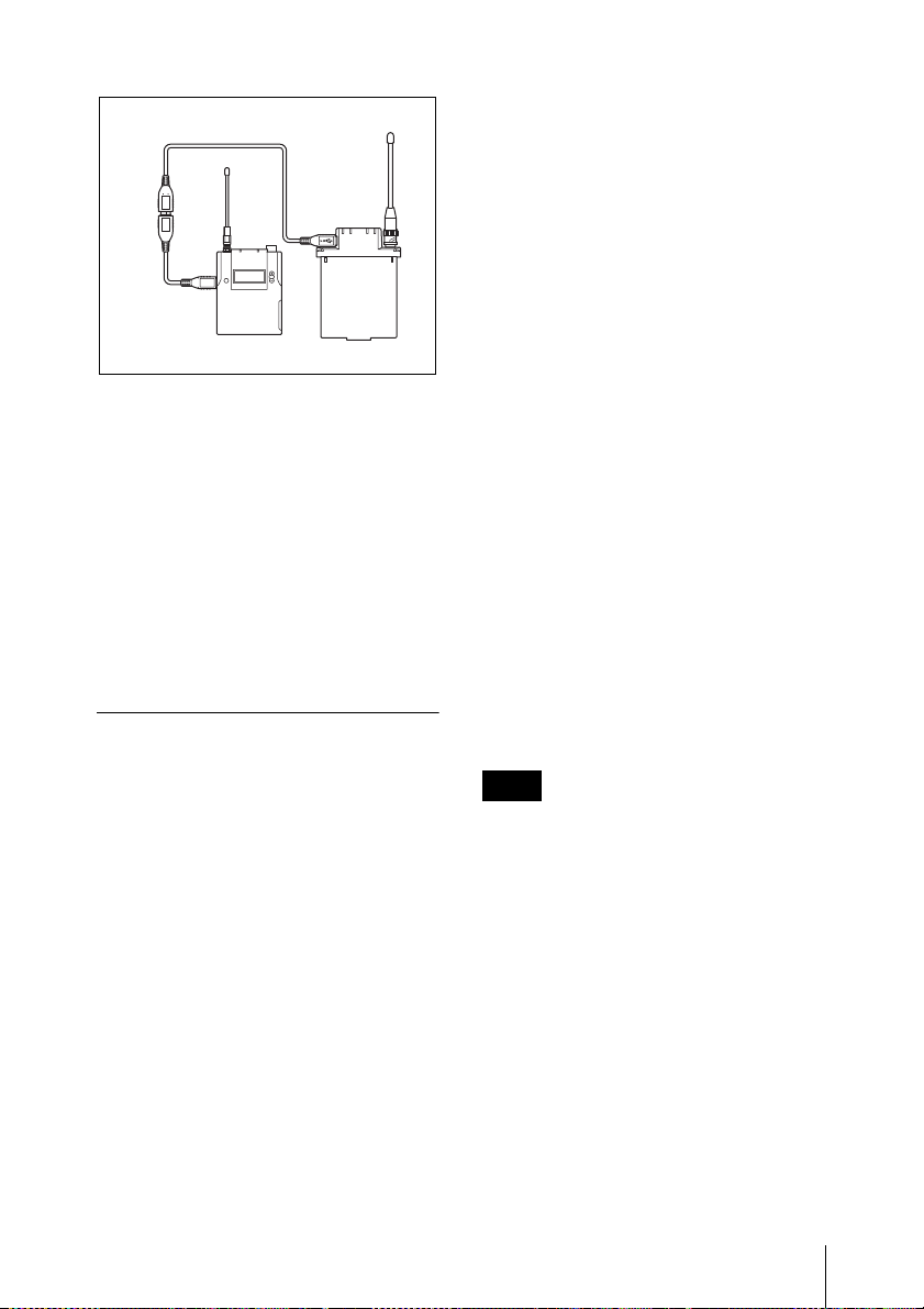
USB cable (supplied)
USB
adapter
cable
(supplied)
When you connect the USB cable, the
encryption key is exchanged
automatically, and encrypted
transmission in secure key mode
begins. Remove the USB cable.
When you select REMOTE:
The receiver searches for a transmitter
that it has been paired with. After the
receiver detects the transmitter, the
transmitter exchanges the encryption
key with the receiver and encrypted
transmission begins.
Using Password Mode
(PASSWORD)
Set this mode when multiple transmitters
are paired with multiple receivers for
encrypted transmission.
If the transmitters and receivers are set with
the same user-designated password, the
audio signal can be decoded. This mode is
useful when multiple transmitters and
receivers are used as a single group, or
when the audio signal from one transmitter
is received by multiple receivers at the same
time.
2 Press the + or – button repeatedly to
select PASSWORD, and then press the
SET button.
3 Enter a password of up to 8 characters
on the receiver.
+: The first press on the + button
displays the character set. You can
then use the + and – buttons to select
the desired character. And then,
pressing the SET button adds the
selected character to the end of the
current name.
– : Deletes the last character in the
current name.
SET: Enters the character or edited
name.
4 Set the encrypted transmission
function on the transmitter to
PASSWORD.
5 On the transmitter, set the same
password that was set on the receiver.
For details on transmitter operations, refer to
the operating instructions supplied with the
transmitter.
Note
It is recommended that you change the
password periodically.
1 With the ENCRYPTION indication on
(in the RX1/2 menu), hold down the
SET button until the item to be set
flashes.
Using the Encrypted Transmission Function
17
Page 18
Using a USB Keyboard
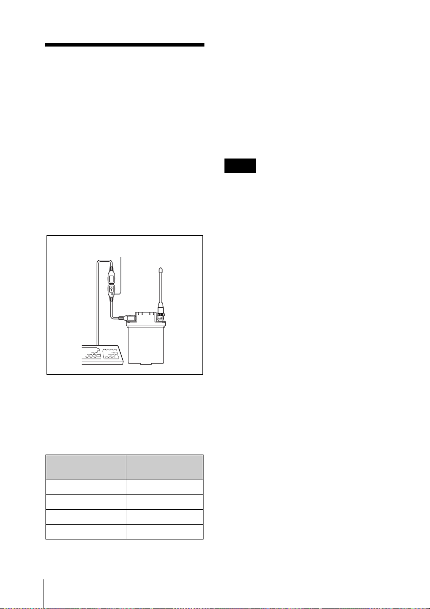
Connecting an optional USB keyboard to
the receiver allows you to perform menu
operations and enter your password for the
encrypted transmission function from the
keyboard.
A Micro USB connector is used on the
receiver. For this reason, use the supplied
USB adapter cable. (When the USB cable is
connected to the receiver, you must remove
the antenna on the USB connecter side.)
<
USB adapter cable (supplied)
Performing menu operations
You can use a USB keyboard to perform the
same menu operations that you perform on
the receiver.
The receiver buttons correspond to the
following keys on a USB keyboard:
To enter your password
You can use a USB keyboard to enter your
password during encrypted transmission.
Characters that can be entered from
a USB keyboard: 0, 1, 2, 3, 4, 5, 6, 7, 8,
9, A, B, C, D, E, F, G, H, I, J, K, L, M, N,
O, P, Q, R, S, T, U, V, W, X, Y, Z
Special key: Backspace (BS), and Delete
key (DEL)
Notes
• The number keys on the keyboard cannot
be used.
• This receiver is compatible with Englishlanguage keyboards only.
• USB keyboards with multiple functions,
such as USB hub and pointing device,
cannot be used.
• Power to the connected keyboard is
supplied by the USB connector on the
receiver. The power rating is 100 mA.
Keyboards that consume more power
than that cannot be used.
• Do not leave the receiver connected to
the keyboard when not in use. If you do,
the batteries in the receiver will be
drained more quickly.
• Text editing should be done with the
alphabet, BS, DEL and Enter keys.
Buttons on the
receiver
MENU SELECT T t
Using a USB Keyboard
18
USB keyboard
SET ENTER
+ R
– r
Page 19
Menu Displays and Detailed Settings
Menu Structure and Hierarchy
Menu structure
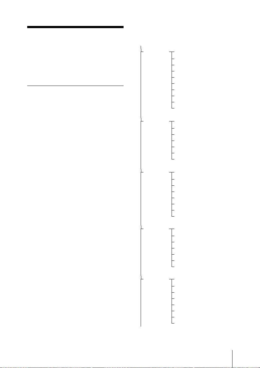
The receiver has 3 kinds of menu, as
follows:
UTILITY menu
A menu that includes meter indications,
functions used in combination with the
DWA-01D/F01D wireless adapter, and
settings for the organic light-emitting diode
display.
RX1/RX2 (tuner 1/2) menu
A menu that includes tuner setting
functions.
TX1/TX2 (virtual transmitter 1/2)
menu
A menu that allows you to check the
settings on the transmitter currently in
communication with the receiver (tuner 1 or
tuner 2).
Menu hierarchy
MENU SELECT
UTILITY
RX1
TX1
RX2
Meter indication
AES/EBU LVL@MIC
SYNC SOURCE
WORD SYNC 75ohm
ANALOG OUTPUT 1
TIME
BRIGHTNESS
DIMMER MODE
FACTORY PRESET
VERSION
BAND
GP/CH
ACT CH SCAN
CLR CH SCAN
RF SQUELCH
ENCRYPTION
SYSTEM DELAY
NAME
RF POWER
INPUT LEVEL
LCF
POWER SAVE
TIME
+48V
RF REMOTE
BAND
GP/CH
ACT CH SCAN
CLR CH SCAN
RF SQUELCH
ENCRYPTION
SYSTEM DELAY
TX2
NAME
RF POWER
INPUT LEVEL
LCF
POWER SAVE
TIME
+48V
RF REMOTE
To UTILITY menu
Menu Displays and Detailed Settings
19
Page 20
Basic Menu Operations
UTILITY Menu
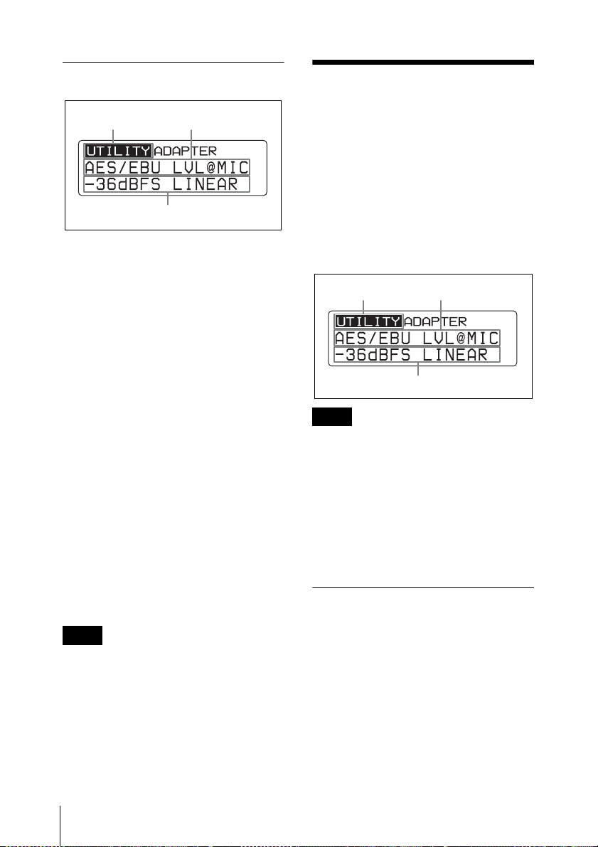
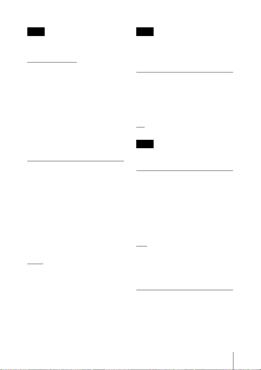
Menu name
Item to be set
Function name
1 Press the MENU SELECT button
repeatedly to select the menu.
Each time you press the MENU
SELECT button, the menu changes in
the following order:
UTILITY, RX1, TX1, RX2, TX2,
UTILITY
2 Press the + or – button repeatedly until
the function to be set appears.
Each time you press the + or – button,
the item to be set changes.
For details, see “Menu hierarchy” on
page 19.
3 Hold down the SET button until the
item to be set flashes.
4 Press the + or – button to change the
setting.
For details on menu operation, see “Basic Menu
Operations” on page 20.
The UTILITY menu includes items related
to the basic receiver settings, including
meter displays.
These functions and parameters are
explained here. Underlined items are the
factory setting.
Menu name
Item to be set
Note
The functions indicated by “ADAPTER”
(from the AES/EBU LVL@MIC function
to the ANALOG OUTPUT1 function) in
the upper-right corner are related to the
AES/EBU output when the receiver is used
in conjunction with the optional DWA01D/F01D wireless adapter. The function
does not operate even when used with a
compatible Sony slot-in type camcorder.
Function name
5 Press the SET button to enter the
setting.
Note
When the tuner is turned off, the menus
corresponding to that tuner are not
displayed.
UTILITY Menu
20
Selecting the AES/EBU
Output Reference Level
(AES/EBU LVL@MIC)
Selects reference level for the AES/EBU
output of the optional DWA-01D/F01D
wireless adapter.
The setting of this function is invalid when
the audio input level of the sending
transmitter is set to LINE (–20 dBFS
headroom signal).
Page 21
Note Note
The function does not operate for analog
output.
When “EXTERNAL” is selected, digital
signals and analog signals will be output
only if there is an external word clock signal
– 36 dBFS LINEAR
: The audio signal
input.
from the transmitter is output with a
headroom of 36 dB.
– 20 dBFS LIMITER: The reference level
is changed to –20 dBFS in conformity with
the normal AES/EBU interface and the
audio signal from the transmitter is
compressed.
– 20 dBFS ST LIMIT: The reference level
is changed to –20 dBFS (as in the –20 dBFS
LIMITER mode above) and audio signal
compression is linked for tuner 1 and tuner
2. Select this setting when sending stereo
audio signals using 2 transmitters.
Terminating the Sync
Signal (WORD SYNC 75ohm)
This function provides termination for the
WORD SYNC connecter on the DWA-
01D/F01D wireless adapter.
ON
OFF: 75-ohm termination is not added.
Note
When the receiver is turned off, the
termination is released.
Selecting the Sync Signal
(SYNC SOURCE)
Selects the sync signal source for the
receiver when it is attached through the
optional DWA-01D/F01D wireless adapter.
The receiver supports an external sync
signal (word clock) of 32 kHz –6% to 96
kHz +6%.
For details on locking the sync signal, refer to the
operating instructions supplied with the adapter.
INTERNAL: The internal sync signal (48
kHz) is used.
: The external sync signal is used on
AUTO
a priority basis. When there is no external
sync signal input, the internal sync signal is
used automatically. The currently selected
sync signal is displayed “INTERNAL” or
“EXTERNAL.”
EXTERNAL: Synchronization with an
external word clock signal. The current
synchronization status is displayed
“UNLOCK” or “LOCK.”
Selecting Output 1 (ANALOG
OUTPUT1)
Selects the OUTPUT1 connecter of the
DWA-01D/F01D wireless adapter.
When the OUTPUT2 connector of the
adapter is being used for AES/EBU output,
the OUTPUT1 connector can be used for
sub-output.
RX1
tuner 1.
RX2: Outputs the audio signal received on
tuner 2.
RX1+2: Mixes and outputs the audio
signals received on tuners 1 and 2.
Showing the Accumulated
Use Time (TIME)
You can display the accumulated battery
use time as a rough estimate of total
receiver usage.
The factory setting is “00:00”.
: 75-ohm termination is added.
: Outputs the audio signal received on
UTILITY Menu
21
Page 22

Resetting the accumulated time
indication
1 Hold down the SET button until the
time indication flashes.
2 Press the – button so “00:00 RESET”
appears, and then press the SET
button.
Setting the Brightness of
the Display
Ten levels of brightness can be selected for
the organic light-emitting diode display.
The selectable settings are the following:
(Dark) 1 2 3 4 5 6 7
Automatic Dimming of the
Display
The organic light-emitting diode display
can be set to dim or turn off after a certain
amount of time.
AUTO OFF: The display turns off after 30
seconds. The display goes on again when
you press the SET, +, or – button.
AUTO DIMMER
30 seconds. The display becomes bright
again when you press the SET, +, or –
button.
ALWAYS ON: The display stays on at the
brightness level set with the BRIGHTNESS
function.
(BRIGHTNESS)
8 9 10 (Bright)
(DIMMER MODE)
: The display dims after
YES, and then press the SET button to
enter. The receiver parameters are reset to
their factory settings.
Displaying the Software
Version (VERSION)
The version of the receiver software can be
displayed.
Resetting Parameters to
their Factory Settings
(FACTORY PRESET)
All parameter settings can be returned to
their factory settings.
Holding down the SET button until a
message appears asking for confirmation.
Press the + or – button repeatedly to select
UTILITY Menu
22
Page 23
RX (tuner) 1/2 Menu
For details on menu operation, see “Basic Menu
Operations” on page 20.
Use this menu to set the digital wireless
receiver functions (the main functions of
this receiver).
The following shows the US model display.
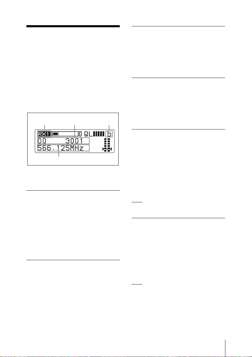
Menu name
Function name
*
Active Channel Scanning
Function
The active channel scan function operates.
For details, see “Using the Active Channel Scan
Function” on page 14.
(ACT CH SCAN)
Clear Channel Scan
Function (CLR CH SCAN)
The clear channel scan function operates.
For details, see “Using the Clear Channel Scan
Function” on page 15.
Using the RF Squelch
Function (RF SQUELCH)
Item to be set
* The antenna currently selected by the diversity
function is indicated by “a” or “b”.
Frequency Band Selection (BAND)
See “Carrier Frequencies and Channel
Steps” on page 36 for factory settings.
For details on the groups and channels included in
each frequency band, refer to “Sony Digital
Wireless Microphone System Frequency Lists” on
the supplied CD-ROM.
Group/Channel (GP/CH) Selection
See “Carrier Frequencies and Channel
Steps” on page 36 for factory settings.
For details, see“Selecting the Frequency Band /
Group / Channel” on page 13.
This function mutes the audio when the RF
signal becomes weak and the sound quality
deteriorates. This prevents interference
from a nearby Sony digital wireless
transmitter set at the same frequency.
20 dBµ: Sets the squelch level to 20 dBµ.
: The RF squelch function does not
OFF
operate.
Encrypted Transmission
Function (ENCRYPTION)
Set the parameters for the encrypted
transmission function.
SECURE KEY: Sets the encryption key
method.
PASSWORD: Sets the password method.
: The encrypted transmission function
OFF
is not used.
For details, see “Using the Encrypted Transmission
Function” on page 16.
RX (tuner) 1/2 Menu
23
Page 24
Display of the Audio Signal
Delay Time
The delay between the time the audio signal
is input on the digital wireless transmitter
and the time it is output on the receiver is
displayed.
Because of the time that it takes for a digital
wireless microphone to process an audio
signal, a delay arises between input on the
transmitter and output on the receiver. The
indication of this delay time is important
when audio signals are also being received
from analog devices, which produce no
delay.
D: Delay time between input on the
transmitter and digital output on the
receiver
A: Delay time between input on the
transmitter and analog output on the
receiver
(When the receiver is inserted in the
camcorder slot, the time is not indicated
because only the digital interface operates.)
(SYSTEM DELAY)
TX (Transmitter
Virtual) 1/2 Menu
For details on menu operation, see “Basic Menu
Operations” on page 20.
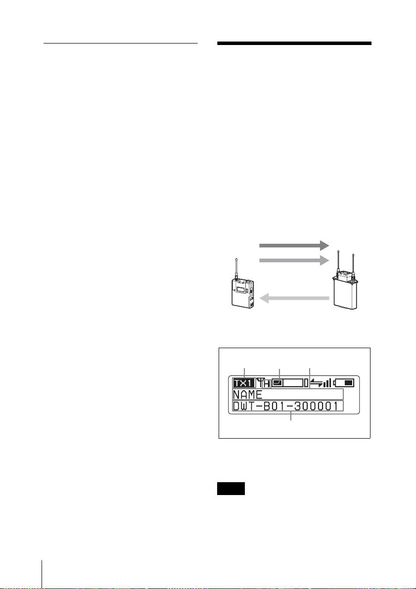
The DWT-B01 Sony digital wireless
transmitter sends not only digital audio
signals, but also various other information
(metadata) related to transmitter settings.
The receiver can display such metadata
received from a transmitter using the TX
(transmitter virtual) 1/2 menu.
Audio RF signal
Metadata
Wireless remote control
TX (Transmitter Virtual) 1/2 Menu
24
Menu name
Item to be set
a) Indicates the power setting of the transmitter
from which transmission is currently being
received.
Note
“NO DATA” appears when the transmitter
is turned off or located outside the service
area. “NO FUNCTION” appears when the
Function name
a)
Page 25

transmitter does not have the metadata
transmission function.
Display of the +48V Power
Setting
(+48V)
Display of the Transmitter’s Name (NAME)
The name of the transmitter from which
transmission is currently being received is
displayed.
Display of the Transmission Power Setting (RF POWER)
The transmission power setting of the
transmitter from which transmission is
currently being received is displayed.
Display of Audio Input Level (INPUT LEVEL)
The audio input level setting of the
transmitter from which transmission is
currently being received is displayed.
Display of the Low-cut Filter Setting (LCF)
The low-cut filter setting of the transmitter
is displayed.
The +48V power setting of the transmitter
is displayed.
Wireless Remote Control
Function (RF REMOTE)
This function must be set to allow the
wireless remote control function to be used
between the transmitter and receiver.
OFF
: Stops the wireless remote control
function.
ON: Starts the wireless remote control
function with the previously paired
receiver.
PAIRING: Executes a new pairing.
For details, see “Usin g the Cross Remote Function”
on page 26.
Display of the Power Save Setting (POWER SAVE)
The power save setting of the transmitter is
displayed.
Display of Accumulated Battery Use Time (TIME)
The accumulated battery use time of the
transmitter is displayed.
TX (Transmitter Virtual) 1/2 Menu
25
Page 26
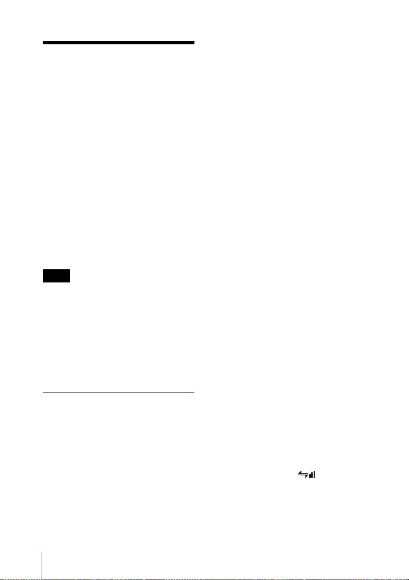
Using the Cross Remote Function
This receiver is equipped with a wireless
remote control function that can be used to
set the parameters (low-cut filter,
attenuation operation, power save mode,
etc.) of the transmitter through the TX1/2
menu. This function makes it easier to
operate and manage the microphone system
while in the field.
This wireless control is 2.4 GHz
IEEE802.15.4 compliant and has no effect
on the RF band of digital wireless audio.
This function is activated when pairing is
established between the transmitter and the
receiver using the RF REMOTE function.
Note
If the software version is not suitable for use
with this receiver, the wireless remote
control function may not function. A
software update may be necessary to enable
proper functioning. For details on software
updates, contact your Sony service
representative.
When using a US model, always update the
software on the transmitter.
1 Press the MENU SELECT button
repeatedly until the TX1/2 menu is
displayed.
2 Press the + or – button repeatedly until
the RF REMOTE indication is
displayed.
3 Hold down the SET button until the
item to be set flashes.
4 Press the + or – button repeatedly to
select PAIRING.
5 Press the SET button to enter the
setting.
Before proceeding to the next step, set
the transmitter to be controlled to
pairing mode.
For details, refer to the operating instructions
supplied with the transmitter.
The receiver starts searching for a
transmitter and then displays the
transmitter name with which pairing
can be executed.
During the search, pressing any
operation key on the receiver will
cancel pairing mode.
6 Press the + or – button repeatedly to
select the transmitter to be paired with
from among those indicated.
Pairing with a Transmitter
The transmitter that you want to control
using the wireless remote control function
is linked to the receiver via the pairing
operation.
In addition to using the following
procedure, you can also set the POWER
switch on tuner 1 or tuner 2 to ON while
holding down the – button to pair the
transmitter with the tuner that you turned
ON.
Using the Cross Remote Function
26
7 Press the SET button to enter the
setting.
The receiver starts to communicate
with the selected transmitter and the
wireless remote control condition
appears in the display. The condition
level (indicated by ) goes up and
the remote control function becomes
operative.
Page 27
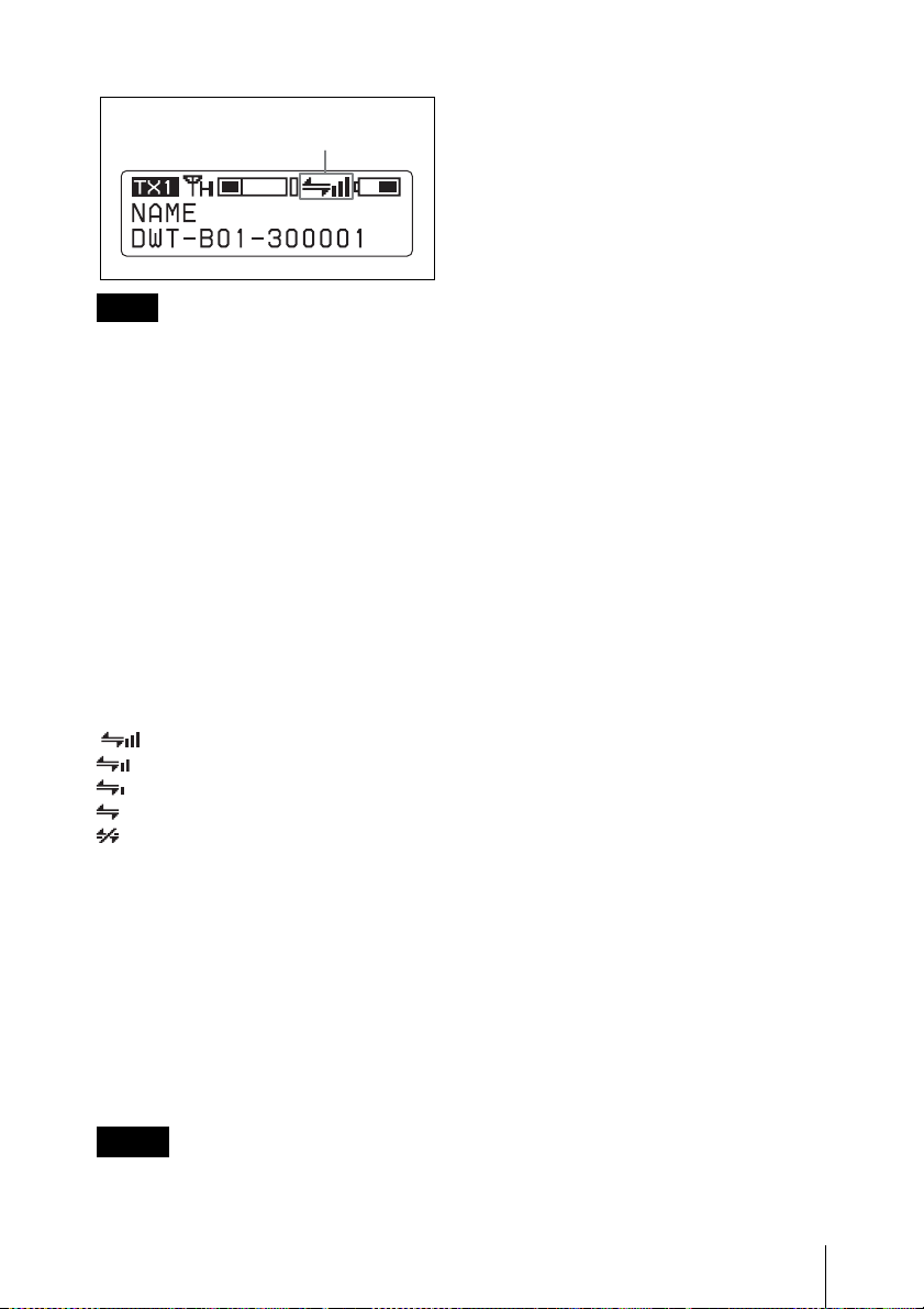
Cross Remote condition
indication
receiver to which it was previously
paired. To use the wireless remote
control function with another transmitter,
you must perform the pairing procedure
again for that transmitter.
• Pairing with multiple transmitters is not
possible.
Note
If the receiving channel (CH) configured on
the receiver is a channel for which use with
the wireless remote control function is
restricted on the transmitter side, the
UNMATCH screen appears.
In such cases, change the receiving channel
on the receiver. If you want to use the
restricted channel, set REMOTE to OFF in
the transmitter’s menu to release the
channel restriction, and manually configure
the transmitter’s channel.
On Cross Remote condition
indication
Indicates the signal transmission condition
of the wireless remote control function (4
levels).
: Good transmission
: Somewhat good transmission
: Somewhat poor transmission
: Poor transmission
: Unable to communicate with
paired receiver
When the wireless remote control function
is off, this indication does not appear.
Using the Cross Remote
function with a previous
pairing
With the TX1/2 menu, select RF REMOTE,
and then select ON.
Notes
• When you set RF REMOTE to ON, the
transmitter will communicate with the
The following transmitter settings
can be performed through Cross
Remote:
• Group/channel/band setting
• RF transmission power setting
• Audio input attenuation setting
• Low-cut filter setting
• Power save setting
• +48V setting
For details on the transmitter settings, see
“Changing the Settings on the Transmitter” on
page 28.
Cancelling the Cross Remote
function
In the TX1/2 menu, select RF REMOTE,
and then OFF.
Notes on the Cross Remote
function
The wireless remote control function on the
receiver uses the 2.4-GHz band and may
thus be subject to interference from other
devices.
• When pairing fails (“Pairing fail” is
displayed), carry out pairing again.
Successful communication between the
transmitter and the receiver has not
occurred within a given amount of time.
Pairing may be harder to do when another
receiver is engaged in pairing nearby.
• When it becomes hard to use the remote
control, the remote control may be
improved by switching the wireless
remote control function off, then on again
in the RF REMOTE display, then re-
Using the Cross Remote Function
27
Page 28
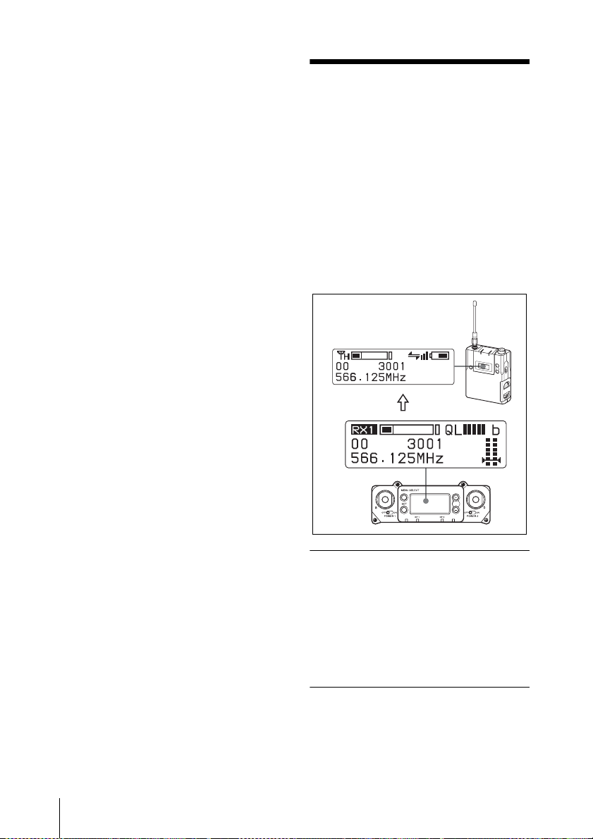
pairing with the transmitter (change to a
channel with less interference).
Changing the Settings on the Transmitter
For details on menu operation, see “Basic Menu
Operations” on page 20.
You can change the settings on the
transmitter that is paired with this receiver
using the RX1/2 menu or the TX1/2 menu.
The following shows the US model display.
Transmitter
Changing the Settings on the Transmitter
28
Receiver
Frequency Band Setting (BAND)
This setting is set through the BAND screen
of the RX1/RX2 menu.
For details, see “Selecting the Frequency Band /
Group / Channel” on page 13.
Group/Channel Setting (GP/
CH)
Only this setting is set through the GP/CH
indication of the RX1/2 menu.
Page 29
For details, see “Selecting the Frequency Band /
Group / Channel” on page 13.
Transmission Power Setting (RF POWER)
You can change the transmission power of
the transmitter.
Audio Input Level Setting
(INPUT LEVEL)
When the input of the transmitter is set to
MIC, the value of the attenuator can be
changed.
The attenuator values that can be selected
depend on the transmitter function.
Low-cut Filter Setting (LCF)
The low-cut filter setting of the transmitter
can be changed.
Note
The frequency selection depends on the
transmitter function.
+48V Power Setting (+48V)
Turns the +48V on the transmitter on or off.
Cross Remote Function Setting (RF REMOTE)
OFF
: Stops the wireless remote control
function.
ON: Starts the wireless remote control
function with the previously paired
receiver.
PAIRING: Executes a new pairing.
For details, see “Usin g the Cross Remote Function”
on page 26.
Power-saving Setting
(POWER SAVE)
To conserve power, this setting allows you
to change the transmitter to sleep mode
using the wireless remote control function.
Note
When the transmitter changes to sleep
mode, transmission of the RF audio signal
and metadata is stopped. For this reason,
“NO DATA” appears for all items in the
TX1/2 menu, except for “SLEEP” in the
POWER SAVE indication.
Changing the Settings on the Transmitter
29
Page 30
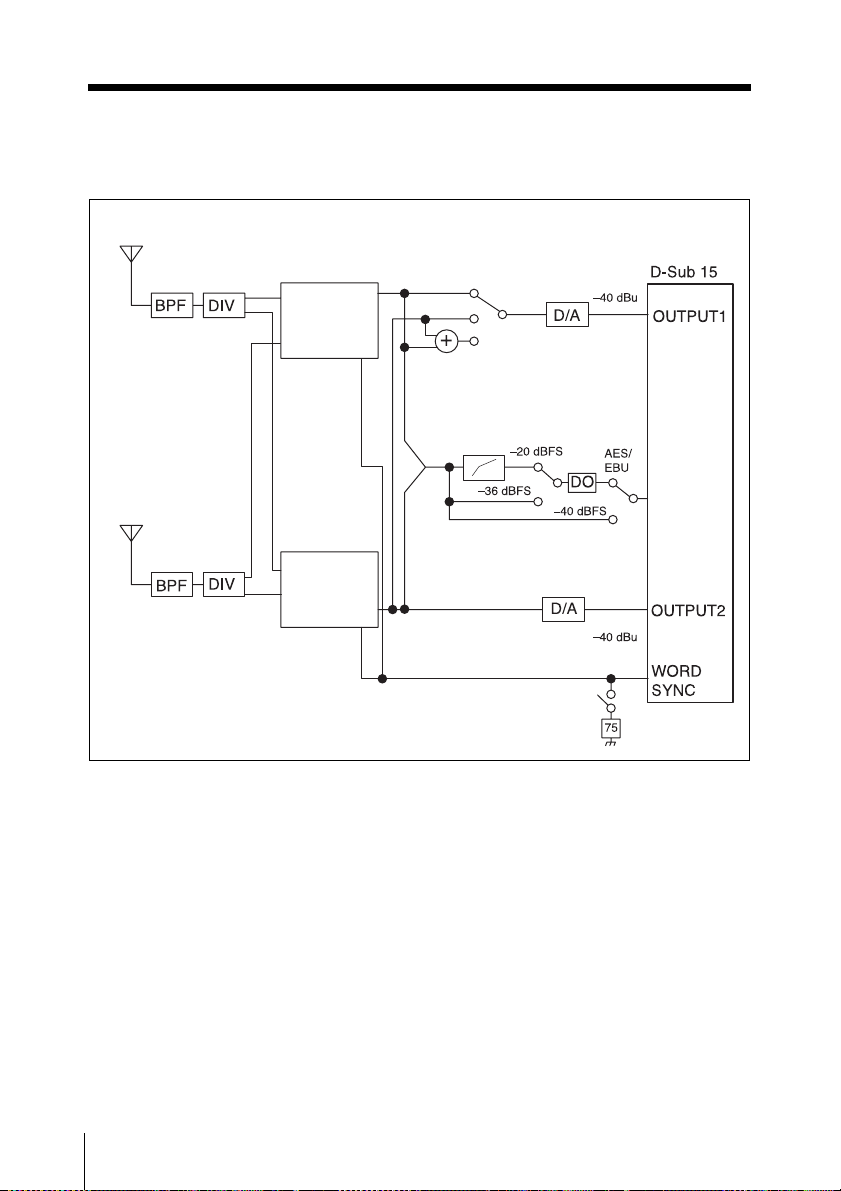
Block Diagram
Antenna a
Antenna b
Digital
wireless
tuner 1
Sync
Digital
wireless
tuner 2
Sync
Tuner 1
Tuner 2
Tuner 1+2
Compressor
Camcorder
interface
Terminate
75 ohms
Analog
Digital
interface
Analog
30
Block Diagram
Page 31
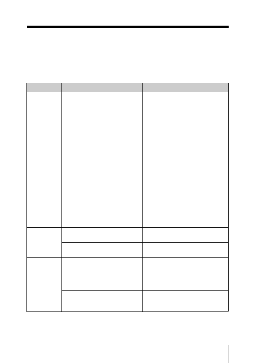
Troubleshooting
If you encounter a problem using this receiver, use the following checklist to find a solution.
For any problems with the transmitter or adapter, refer to the operating instructions supplied
with the respective device. If the problem persists, consult your Sony dealer.
Symptom Meanings Remedy
The receiver
does not turn
on.
There is no
sound.
The sound is
weak.
There is
distortion in
the sound.
The receiver is not correctly
inserted into the slot of the
camcorder or the optional DWA01D/F01D wireless adapter.
The channel setting on the
transmitter is different from that
on the receiver.
The transmitter is turned off. Check the power supply or battery
The setting of the encrypted
transmission function on the
receiver is different from that on
the transmitter.
When the receiver is attached
through the optional DWA-01D/
F01D wireless adapter, the
setting of the sync signal is not
appropriate.
The attenuation level on the
transmitter is too high.
The AES/EBU reference output
level is set to –36 dBFS LINEAR.
The attenuation level of the
transmitter is zero or too low.
A LINE level signal is being input
while the input level of the
transmitter set to MIC.
Insert the receiver until it is firmly
and completely in, and then secure
it with the mounting screws.
Use the same channel setting on
both the transmitter and receiver.
of the transmitter.
Confirm that the setting of the
encrypted transmission function is
the same on both the transmitter
and the receiver.
Using the sync signal selection
(SYNC SOURCE) function, set the
sync signal to INTERNAL.
When an external sync signal is
used, confirm the connection of the
sync signal, and set to AUTO or
EXTERNAL.
Set the attenuator on the
transmitter to an appropriate level.
Set the reference output level
according to the use (see page 20).
The input level of the transmitter is
extremely high. Adjust the
attenuation level on the transmitter
so that there is no distortion to the
sound.
Refer to the operating instructions
supplied with the transmitter and
set the input level to LINE.
Troubleshooting
31
Page 32
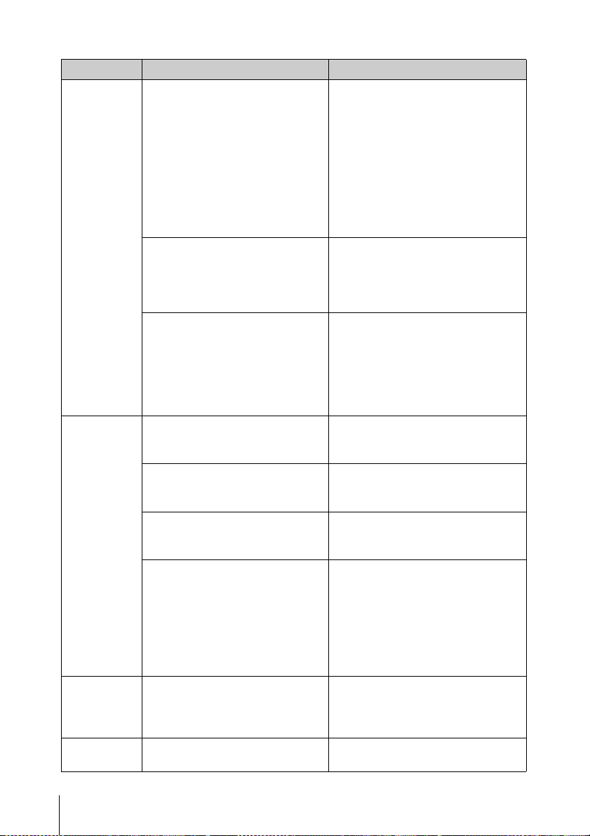
Symptom Meanings Remedy
There is
sound
interruption
or noise.
Wireless
remote
control is not
possible.
The USB
keyboard
does not
work.
The display is
too dark.
The RF indicator lights up even
when the transmitter is turned off.
Two or more transmitters are set
to the same channel.
The channel is not set within the
same channel group.
Pairing has not been established
between the transmitter and
receiver.
The receiver is too far from the
transmitter for communication to
occur.
The transmitter that was paired
with the receiver has been paired
with another receiver.
The software version of the
transmitter is not suitable for use
with this receiver.
You are using a USB keyboard
that is not compatible with the
receiver.
The display brightness is set to
low.
Jamming radio waves are being
received. Set the channel whose
RF indicator on the receiver does
not light up, and then set that same
channel on the transmitter. When
two or more transmitters are being
used, change to another channel
group that is unaffected by jamming
radio waves. When doing this, the
clear channel scan function is
useful.
It is not possible to use two or more
transmitters that are set to the same
channel. Refer to the Sony digital
wireless frequency lists and reset
the transmitter channel.
The channel plan of the receiver
use is set so that no signal
interference occurs when two or
more transmitters are used
simultaneously. Set each
transmitter to a different channel
within the same channel group.
Carry out pairing (see page 26).
Check the condition level. If it is low,
decrease the distance between the
transmitter and the receiver.
Carry out pairing again with the
transmitter that you want to control.
Refer to the supplied transmitter
software compatibility table, and
confirm whether the software
version of the transmitter is suitable
for use with this receiver. If it is not
suitable, software update is
necessary. Contact your Sony
service representative.
Check the conditions for using a
USB keyboard with the receiver
(see page 18).
Adjust the brightness of the display
(see page 22).
32
Troubleshooting
Page 33

Important Notes on Operation
Notes on Using the Receiver
• The digital wireless microphone system
product must be used within a
temperature range of 0°C to 50°C (32°F
to 122°F).
• Operating the receiver near electrical
equipment (motors, transformers, or
dimmers) may cause it to be affected by
electromagnetic induction. Keep the
receiver as far from such equipment as
possible.
• The presence of the lighting equipment
may produce electrical interference over
the entire frequency range. Position the
receiver so that interference is
minimized.
• To avoid degradation of the signal-tonoise ratio, do not use the receiver in
noisy places or in locations subject to
vibration, such as the following:
- near electrical equipment, such as
motors, transformers or dimmers
- near air conditioning equipment or
places subject to direct air flow from
an air conditioner
- near public address loudspeakers
- where adjacent equipment might
knock against the tuner
Keep the receiver as far from such
equipment as possible or use buffering
material.
active gas, clean its surface as well as the
connectors with a dry, soft cloth soon
after use. Lengthy use of the receiver in
such places or not cleaning it after its use
in such places may shorten its life.
• Clean the surface and the connectors of
the receiver with a dry, soft cloth. Never
use thinner, benzene, alcohol or any other
chemicals, since these may mar the
finish.
Transmitter software version
If the software version is not suitable for use
with this receiver, the wireless remote
control function may not function. A
software update may be necessary to enable
proper functioning. For details on software
updates, contact your Sony service
representative.
When using a US model, always update the
software on the transmitter.
Audio degradation due to
weak reception
In a digital wireless system, sound quality is
maintained up to the maximum
transmission range. Beyond this point, as
the radio wave becomes weaker, data
synchronization is lost and the connection
finally breaks. Sony digital wireless
systems suppress the occurrence of large
noise between these two points as the signal
weakens. As a result, digital processing is
conducted in a way that allows the signal to
degrade in a very natural way.
On Cleaning
• If the receiver is used in a very humid or
dusty place or in a place subject to an
Important Notes on Operation
33
Page 34

To prevent electromagnetic
interference from portable
communication devices
The use of portable telephones and
other communication devices near
the DWR-S02D may result in
malfunction and interference with
audio signals. It is recommended that
portable communication devices near
the DWR-S02D be turned off.
Specifications
Tuner section
Type of reception
Space diversity
Circuit system
Double superheterodyne
Local oscillators
Crystal-controlled PLL synthesizer
RF input terminal
BNC-R, 50 ohms
Sensitivity
20 dBµ or less (at ambient
temperature 25 °C (77 °F),
bit error rate = 1 x 10
no decline in S/N ratio)
Audio section
Audio output connector
D-sub 15 pin (male) (x1)
Reference output level
Analog: –40 dBu
Digital: –36 dBFS/–20 dBFS
(switchable)
Dynamic range
106 dB or more (A-weighted)
T.H.D 0.03% or less (0 dBu = 0.775 Vrms)
Audio delay
2.1 ms (Analog output in
combination with the DWA01D/F01D)
1.9 ms (AES/EBU output in
combination with the DWA01D/F01D and through a digital
connection with a camcorder)
-5
,
34
General
Operating voltage
7 V DC
Consumption current
500 mA or less (at 7 V DC)
Specifications
Page 35
Operating temperature
0 to 50 °C (32 to 122 °F)
Storage temperature
–20 to +60 °C (–4 to +140 °F)
Wireless remote control
2.4-GHz IEEE802.15.4 compliant
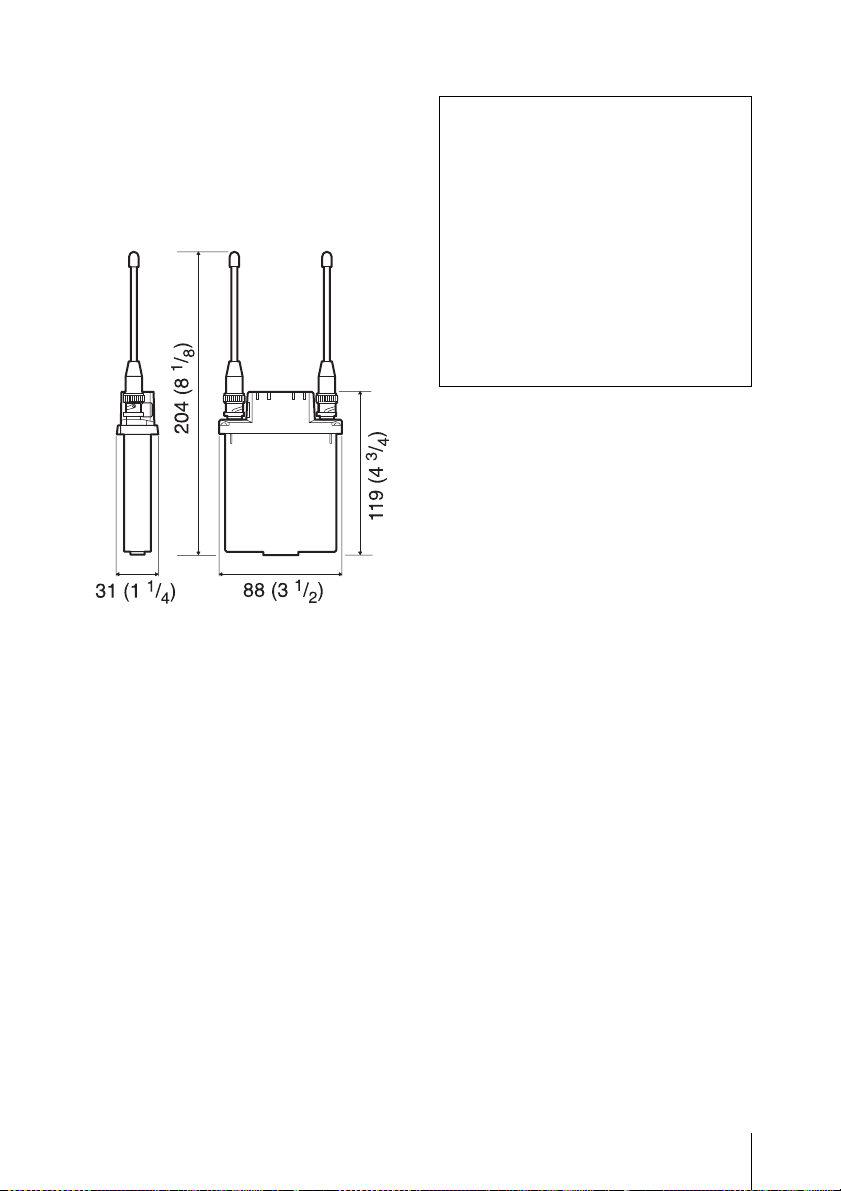
Dimensions (Unit: mm (inches))
Mass Approx. 280 g (10 oz) (including
the supplied antennas)
Supplied accessories
Antenna (2)
USB adapter cable (1)
USB cable (1)
Operating Instructions (1)
CD-ROM (1)
Frequency band label (1)
Note
Always verify that the unit is operating
properly before use. SONY WILL NOT
BE LIABLE FOR DAMAGES OF ANY
KIND INCLUDING, BUT NOT
LIMITED TO, COMPENSATION OR
REIMBURSEMENT ON ACCOUNT
OF THE LOSS OF PRESENT OR
PROSPECTIVE PROFITS DUE TO
FAILURE OF THIS UNIT, EITHER
DURING THE WARRANTY PERIOD
OR AFTER EXPIRATION OF THE
WARRANTY, OR FOR ANY OTHER
REASON WHATSOEVER.
Design and specifications are subject to
change without notice.
Specifications
35
Page 36
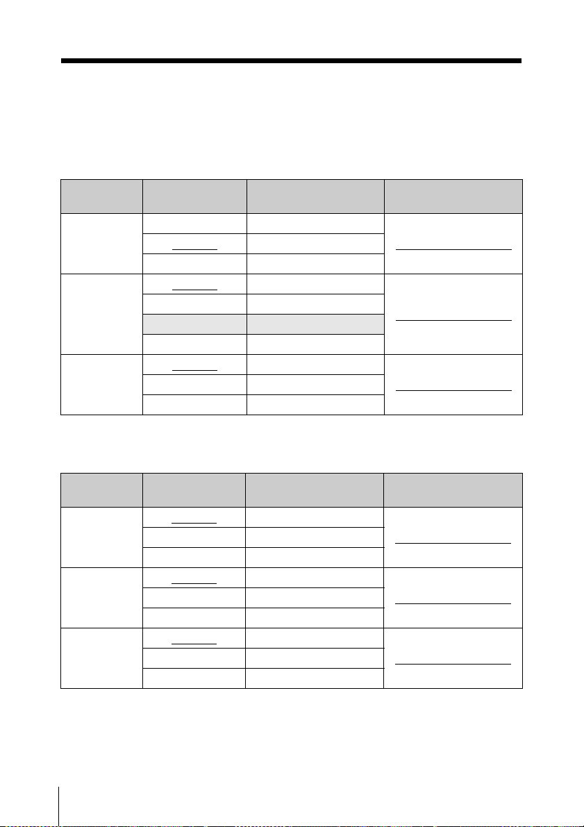
Carrier Frequencies and Channel Steps
Underlined items are the factory setting.
US models
Channel step: 25 kHz
Model No. Frequency band Frequency Group/channel
TV14-17 470.125 - 493.875 MHz
U1424
U3040
U4250
TV18-21 494.125 - 517.875 MHz
TV22-25 518.125 - 541.875 MHz
TV30-33
TV34-36 590.125 - 607.875 MHz
TV37 Not available
TV38-41 614.125 - 637.875 MHz
TV42-45
TV46-49 662.125 - 685.875 MHz
TV50-51 686.125 - 697.875 MHz
566.125 - 589.875 MHz
638.125 - 661.875 MHz
European models
Channel step: 25 kHz
Model No. Frequency band Frequency Group/channel
CE3338
CE4248
CE5157
TV33-35
TV36-37 590.025 - 606.000 MHz
TV38-40 606.025 - 630.000 MHz
TV42-44
TV45-47 662.025 - 686.000 MHz
TV48-50 686.025 - 710.000 MHz
TV51-53
TV54-56 734.025 - 758.000 MHz
TV57-59 758.025 - 782.000 MHz
566.025 - 590.000 MHz
638.025 - 662.000 MHz
710.025 - 734.000 MHz
(factory setting)
00 1801 494.125 MHz
00 3001 566.125 MHz
00 4201 638.125 MHz
(factory setting)
00 3301 566.125 MHz
00 4201 638.125 MHz
00 5101 710.125 MHz
Carrier Frequencies and Channel Steps
36
Page 37

Carrier Frequencies and Channel Steps
37
Page 38

Carrier Frequencies and Channel Steps
38
Page 39

Carrier Frequencies and Channel Steps
39
Page 40

Sony Corporation
Printed in Japan
 Loading...