

Sony RM-PJ25, VPL-HW40ES Service Manual

VIDEO PROJECTOR
VPL-HW40ES
REMOTE COMMANDER
RM-PJ25
SERVICE MANUAL
1st Edition

!警告
このマニュアルは,サービス専用です。
お客様が,このマニュアルに記載された設置や保守,点検,修理などを行うと感電や火災,
人身事故につながることがあります。
危険をさけるため,サービストレーニングを受けた技術者のみご使用ください。
! WARNING
This manual is intended for qualifi ed service personnel only.
To reduce the risk of electric shock, fi re or injury, do not perform any servicing other than that
contained in the operating instructions unless you are qualifi ed to do so. Refer all servicing to
qualifi ed service personnel.
! WARNUNG
Die Anleitung ist nur für qualifi ziertes Fachpersonal bestimmt.
Alle Wartungsarbeiten dürfen nur von qualifi ziertem Fachpersonal ausgeführt werden. Um die
Gefahr eines elektrischen Schlages, Feuergefahr und Verletzungen zu vermeiden, sind bei
Wartungsarbeiten strikt die Angaben in der Anleitung zu befolgen. Andere als die angegeben
Wartungsarbeiten dürfen nur von Personen ausgeführt werden, die eine spezielle Befähigung
dazu besitzen.
! AVERTISSEMENT
Ce manual est destiné uniquement aux personnes compétentes en charge de l’entretien. Afi n
de réduire les risques de décharge électrique, d’incendie ou de blessure n’effectuer que les
réparations indiquées dans le mode d’emploi à moins d’être qualifi é pour en effectuer d’autres.
Pour toute réparation faire appel à une personne compétente uniquement.
警告
万一,異常が起きた際に,お客様が電源を切ることが
できるように,設置の際には,機器近くの固定配線内
に専用遮断装置を設けるか,機器使用中に,容易に抜
き差しできるコンセントに電源プラグを接続してくだ
さい。
WARNING
When installing the unit, incorporate a readily accessible
disconnect device in the fi xed wiring, or connect the
power cord to a socket-outlet which must be provided
near the unit and easily accessible, so that the user can
turn off the power in case a fault should occur.
WARNUNG
Beim Einbau des Geräts ist daher im Festkabel
ein leicht zugänglicher Unterbrecher einzufügen,
oder das Netzkabel muß mit einer in der Nähe
des Geräts befi ndlichen, leicht zugänglichen
Wandsteckdose verbunden werden, damit sich bei
einer Funktionsstörung die Stromversorgung zum Gerät
jederzeit unterbrechen läßt.
For kundene i Norge
Dette utstyret kan kobles til et IT-strømfordelingssystem.
VPL-HW40ES
注意
注意
FÖRSIKTIGHET!
指定以外の電池に交換すると,破裂する危険があります。
必ず指定の電池に交換してください。
使用済みの電池は,国または地域の法令に従って
処理してください。
CAUTION
Danger of explosion if battery is incorrectly replaced.
Replace only with the same or equivalent type recommended by the manufacturer.
When you dispose of the battery, you must obey the
law in the relative area or country.
ATTENTION
Il y a danger d’explosion s’il y a remplacement incor-
rect de la batterie. Remplacer uniquement avec
une batterie du même type ou d’un type équivalent
recommandé par le constructeur.
Lorsque vous mettez la batterie au rebut, vous devez
respecter la législation en vigueur dans le pays ou la
région où vous vous trouvez.
Fara för explosion vid felaktigt placerat batteri.
Byt endast mot samma eller likvärdig typ av batteri,
enligt tillverkarens rekommendationer.
När du kasserar batteriet ska du följa rådande lagar
för regionen eller landet.
PAS PÅ
Fare for eksplosion, hvis batteriet ikke udskiftes
korrekt.
Udskift kun med et batteri af samme eller tilsvarende
type, som er anbefalet af fabrikanten.
Når du bortskaffer batteriet, skal du følge
lovgivningen i det pågældende område eller land.
HUOMIO
Räjähdysvaara, jos akku vaihdetaan virheellisesti.
Vaihda vain samanlaiseen tai vastaavantyyppiseen,
valmistajan suosittelemaan akkuun.
Noudata akun hävittämisessä oman maasi tai
alueesi lakeja.
VORSICHT
Explosionsgefahr bei Verwendung falscher Batterien.
Batterien nur durch den vom Hersteller empfohlenen
oder einen gleichwertigen Typ ersetzen.
Wenn Sie die Batterie entsorgen, müssen Sie die
Gesetze der jeweiligen Region und des jeweiligen
Landes befolgen.
FORSIKTIG
Eksplosjonsfare hvis feil type batteri settes i.
Bytt ut kun med samme type eller tilsvarende
anbefalt av produsenten.
Kasser batteriet i henhold til gjeldende avfallsregler.
注意
如果更换的电池不正确,就会有爆炸的危险。
只更换同一类型或制造商推荐的电池型号。
处理电池时,必须遵守相关地区或国家的法律。
VPL-HW40ES
1 (P)


Table of Contents
Manual Structure
Purpose of this manual ............................................................ 3 (E)
Related manuals ...................................................................... 3 (E)
1. Service Overview
1-1. Appearance Figure/Board Location ..........................1-1 (E)
1-2. Tighten Torque ..........................................................1-2 (E)
1-3. Disassembly ..............................................................1-3 (E)
1-3-1. Top Cover Assembly and HA Board ................ 1-5 (E)
1-3-2. HB Board and TL Board .................................. 1-6 (E)
1-3-3. Front Cover Assembly ..................................... 1-6 (E)
1-3-4. NF Board .........................................................1-7 (E)
1-3-5. DC Fan (EX) ....................................................1-7 (E)
1-3-6. C Board-1 ......................................................... 1-8 (E)
1-3-7. C Board-2 and U Board ...................................1-9 (E)
1-3-8. C Board-3 ....................................................... 1-10 (E)
1-3-9. Optical Unit Assembly ...................................1-10 (E)
1-3-10. DC Fan ........................................................... 1-11 (E)
1-3-11. GA Board .......................................................1-12 (E)
1-3-12. GB Board ....................................................... 1-13 (E)
1-3-13. Power Supply Unit ......................................... 1-14 (E)
1-3-14. QB Board ....................................................... 1-15 (E)
1-3-15. DC Fan and V Board-1 .................................. 1-16 (E)
1-3-16. DC Fan and V Board-2 .................................. 1-17 (E)
1-3-17. QA Board .......................................................1-18 (E)
1-3-18. EM Board ....................................................... 1-19 (E)
1-4. Optional Fixtures ..................................................... 1-20 (E)
1-4-1. Extension Boards and Extension Cables .......1-20 (E)
1-4-2. Connection .....................................................1-21 (E)
1-5. Indicator ..................................................................1-23 (E)
1-6. Circuit Description .................................................. 1-24 (E)
1-7. Disconnecting/
Connecting the Flexible Card Wires ....................... 1-25 (E)
1-8. Lead-free Solder ......................................................1-26 (E)
2. Electrical Adjustments
2-1. Preparations ...............................................................2-1 (E)
2-1-1. Required Equipment ........................................2-1 (E)
2-1-2. How to Enter the Service Mode ....................... 2-1 (E)
2-1-3. How to Enter the Model Name Display
(Shop Demonstration) Mode ...........................2-2 (E)
2-1-4. How to Enter the Motionflow
(Shop Demonstration) Mode ...........................2-2 (E)
2-2. Notes on Servicing ....................................................2-3 (E)
2-2-1. When the Optical Unit Assembly is
Replaced...........................................................2-3 (E)
2-2-2. When Replacing the QA Board .......................2-3 (E)
2-2-3. When Replacing the C Board ..........................2-3 (E)
2-2-4. When the GA, GB, HA, HB, NF, QB, TL, U, or
V Board is Replaced ........................................2-3 (E)
2-3. White Balance Adjustment ........................................ 2-4 (E)
2-3-1. D93 Mode of Video .........................................2-4 (E)
2-3-2. D75 Mode of Video .........................................2-4 (E)
2-3-3. D65 Mode of Video .........................................2-5 (E)
2-3-4. D55 Mode of Video .........................................2-5 (E)
2-3-5. Custom Setting ................................................. 2-5 (E)
2-4. Adjust Value Writing .................................................2-6 (E)
2-4-1. Panel Driver Gain B Data Copy ......................2-6 (E)
2-4-2. Panel Alignment Data Copy ............................2-6 (E)
2-5. Panel Driver Gain B Adjustment ...............................2-6 (E)
2-6. Software Upgrade Method ........................................2-7 (E)
2-6-1. Preparation .......................................................2-7 (E)
2-6-2. SUB CPU Upgrade ..........................................2-8 (E)
2-6-3. Scan Converter Upgrade ..................................2-9 (E)
2-6-4. Data Write Method of 3DGamma/LookUpTable/
DDC/NVM/ABGamma/LCK/OGMData/
CSMatrixTable ...............................................2-10 (E)
2-6-5. Data Obtain Method of 3DGamma/LookUpTable/
DDC/NVM/ABGamma/LCK/OGMData/
CSMatrixTable from the Board ..................... 2-12 (E)
2-7. Memory ................................................................... 2-13 (E)
2-8. Adjustment Item Initialize Data .............................. 2-16 (E)
VPL-HW40ES
1 (E)

3. Spare Parts
6. Board Layouts
3-1. Notes on Repair Parts ...................................................... 3-1
3-2. Exploded Views ............................................................... 3-2
3-3. Electrical Parts List .........................................................3-9
3-4. Packing Materials & Supplied Accessories ................... 3-36
4. Block Diagrams
Overall ............................................................................. 4-1
QA ................................................................................... 4-2
HA ................................................................................... 4-3
HB ................................................................................... 4-3
NF ....................................................................................4-3
QB ................................................................................... 4-3
TL .................................................................................... 4-3
U ...................................................................................... 4-3
V ...................................................................................... 4-3
C ...................................................................................... 4-5
GA ................................................................................... 4-7
GB ................................................................................... 4-7
C ...................................................................................... 6-2
GA ...................................................................................6-4
GB ................................................................................... 6-6
QA ...................................................................................6-8
EM ................................................................................. 6-10
HA ................................................................................. 6-10
HB ................................................................................. 6-10
NF .................................................................................. 6-11
QB ................................................................................. 6-11
TL .................................................................................. 6-11
U .................................................................................... 6-11
V .................................................................................... 6-11
5. Schematic Diagrams
HA ................................................................................... 5-2
HB ................................................................................... 5-2
C ...................................................................................... 5-3
EM ................................................................................. 5-13
GA ................................................................................. 5-14
GB ................................................................................. 5-15
QA ................................................................................. 5-17
NF ..................................................................................5-28
QB ................................................................................. 5-28
TL .................................................................................. 5-28
U .................................................................................... 5-28
V .................................................................................... 5-28
Frame Wiring.................................................................5-29
2 (E)
VPL-HW40ES

Purpose of this manual
Related manuals
Manual Structure
This manual is the Service Manual of the Video Projector VPL-HW40ES.
This manual contains the service overview, adjustments, spare parts, block diagrams,
schematic diagrams, and board layouts.
In addition to this Service Manual, the following manuals are provided.
. “Operating Instruction” CD-ROM (Supplied with unit)
This manual is necessary for application and operation of this unit.
. Protocol Manual (Available on request)
This manual describes the protocol for controlling this unit.
VPL-HW40ES
3 (E)

Section 1
Service Overview
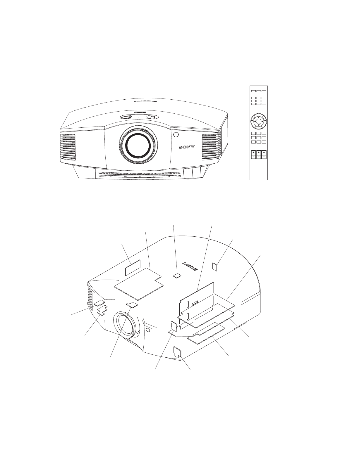
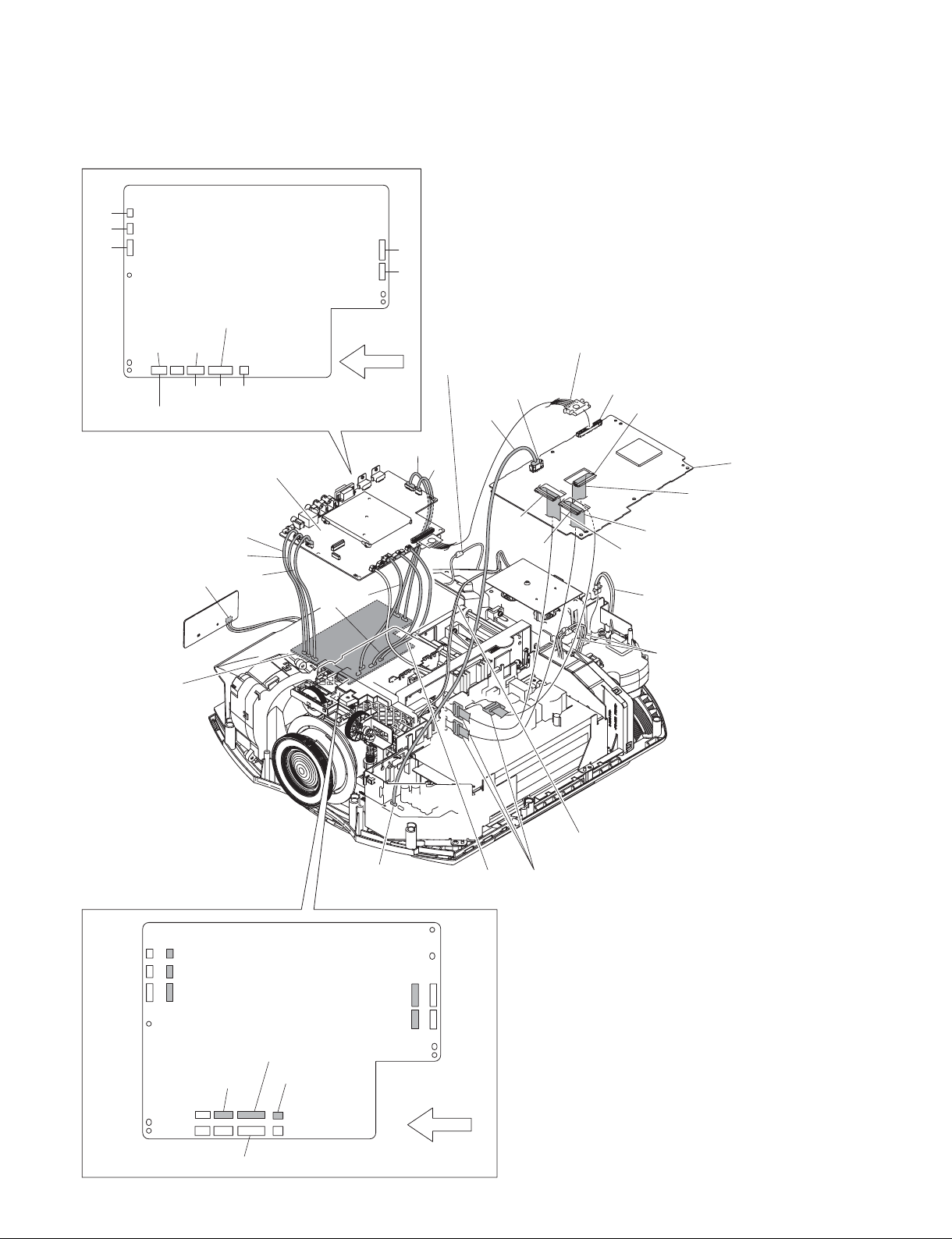
1-1. Appearance Figure/Board Location
Appearance figure
RM-PJ25
Board location
QB
U
QA
HA
V
HB
NF
EM
C
TL
GA
GB
Power supply unit
VPL-HW40ES
1-1 (E)

1-2. Tighten Torque
Tighten the each screw with the torque below.
n
When using the torque driver with the notation of cN.m, interpret it as follows.
Example: 0.8 N.m = 80 cN.m
. BVTP3 x 8: 0.80 ?0.12 N.m (8.16 ?1.22 kgf.cm)
. BVTP3 x 12: 0.80 ?0.12 N.m (8.16 ?1.22 kgf.cm)
. BVWHTP3 x 12: 0.80 ?0.12 N.m (8.16 ?1.22 kgf.cm)
. PSW3 x 8: 0.80 ?0.12 N.m (8.16 ?1.22 kgf.cm)
. PSW4 x 8: 1.40 ?0.2 N.m (14.3 ?2.0 kgf.cm)
. PSW4 x 16: 1.40 ?0.2 N.m (14.3 ?2.0 kgf.cm)
. SP4-40 UNC screw: 0.53 ?0.07 N.m (5.40 ?0.71 kgf.cm)
. Tapping screw1.7 x 4: 0.15 ?0.01 N.m (1.53 ?0.10 kgf.cm)
. Hexagon screw (for connector): 0.53 ?0.07 N.m (5.40 ?0.71 kgf.cm)
1-2 (E)
VPL-HW40ES
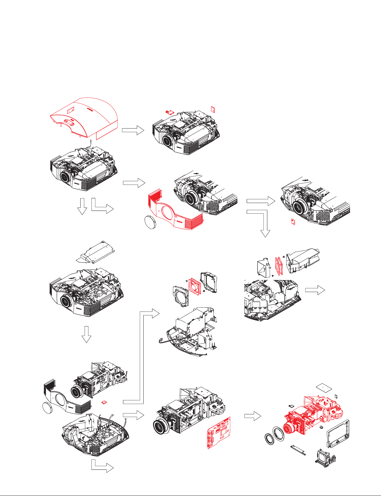
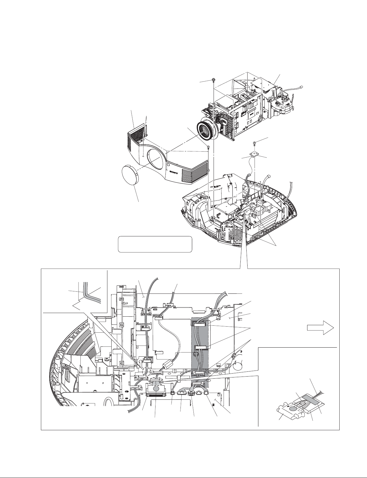
1-3. Disassembly
n
Remove parts in the order of numbers shown in the figure, in this section.
1-3-1. Top Cover Assembly and HA Board
1-3-2. HB Board and TL Board
1-3-6. C Board-1
A
1-3-3. Front Cover Assembly
1-3-10. DC fan
1-3-4. NF Board
1-3-5. DC Fan (EX)
C
VPL-HW40ES
1-3-7. C Board-2 and U Board
B
1-3-8. C Board-3
1-3-9. Optical Unit Assembly
1-3 (E)
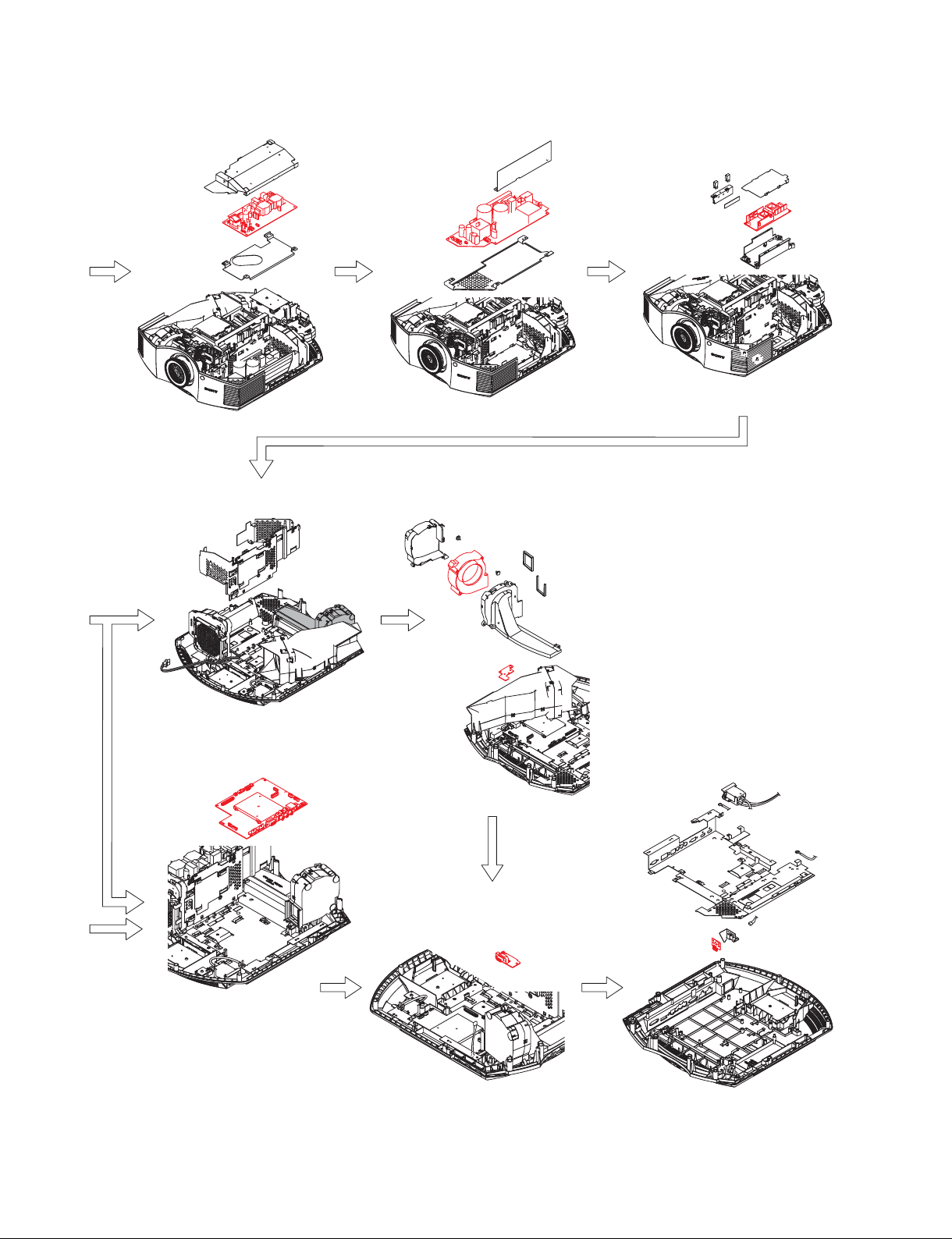
A
1-3-11. GA Board 1-3-12. GB Board 1-3-13. Lamp Power Supply
1-3-15. DC Fan and V Board-1 1-3-16. DC Fan and V Board-2
B
C
1-3-17. QA Board 1-3-18. EM Board
1-3-14. QB Board
C
1-4 (E)
VPL-HW40ES
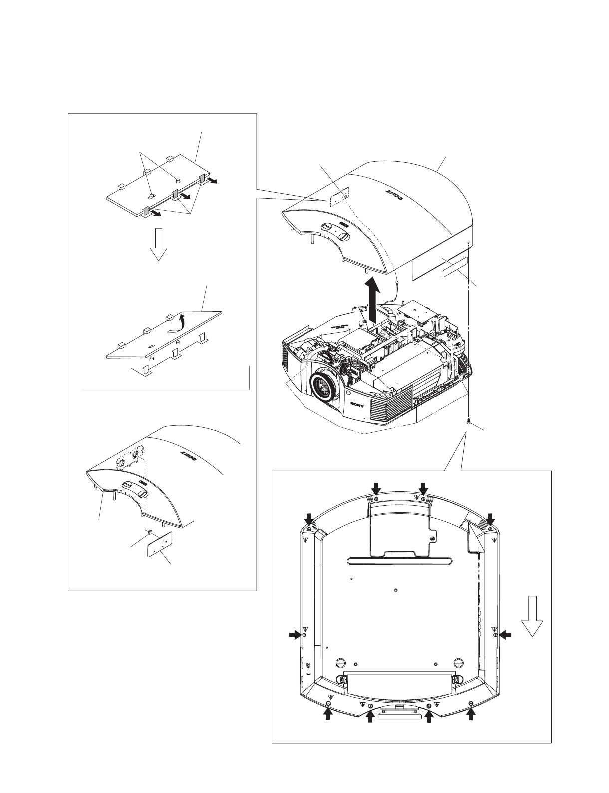
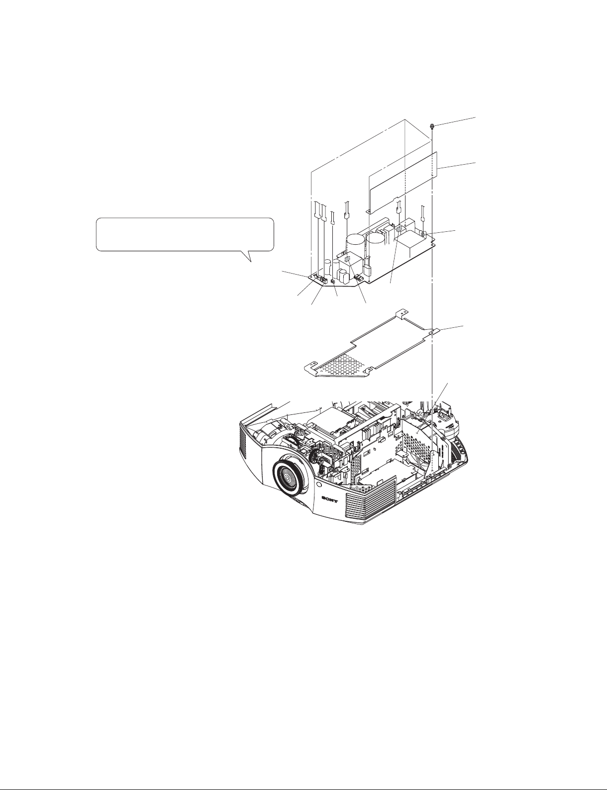
1-3-1. Top Cover Assembly and HA Board
HA board
4 Two dowels
5 Remove the HA board in the
direction of the arrow A.
A
3 Three hooks
2 HA board
CN11
9 Top cover assembly
8 Lens caution label
1 Ten screws
(BVTP3 x 12)
Top cover assembly
6 Button (P)
VPL-HW40ES
7 HA board
Front side
1-5 (E)
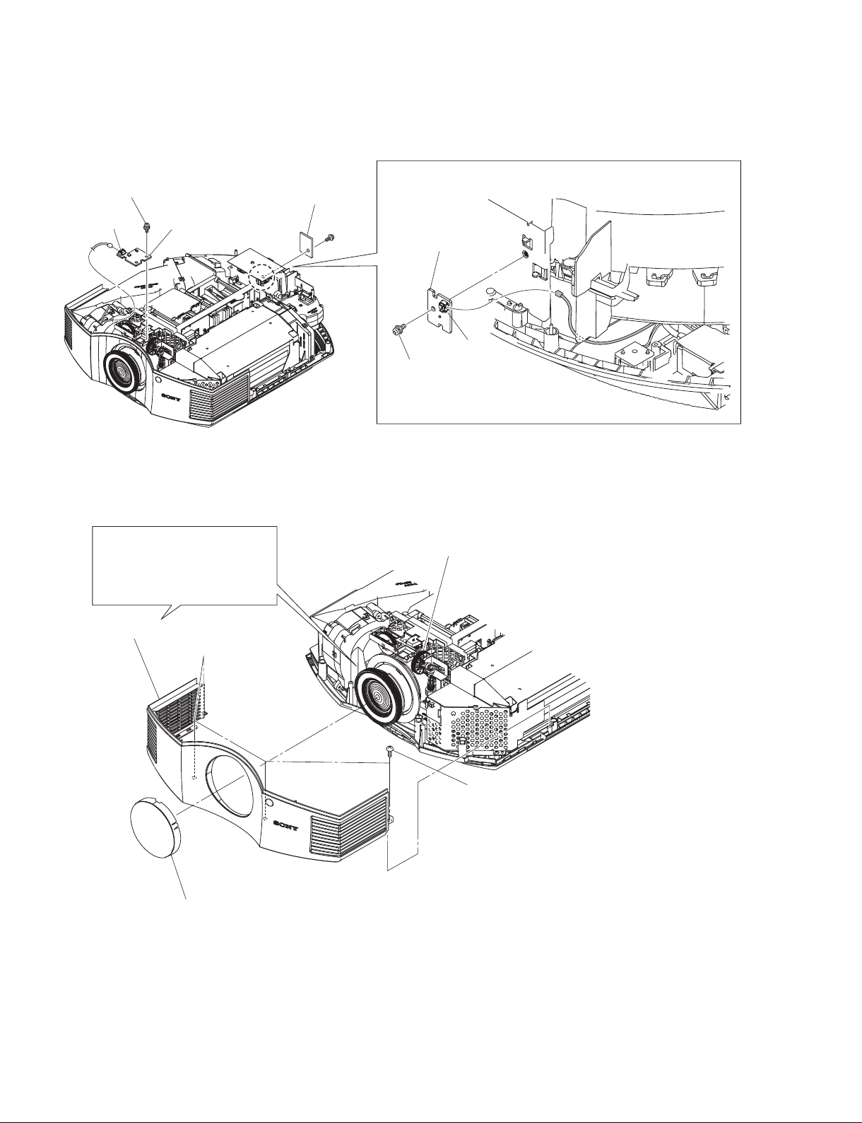
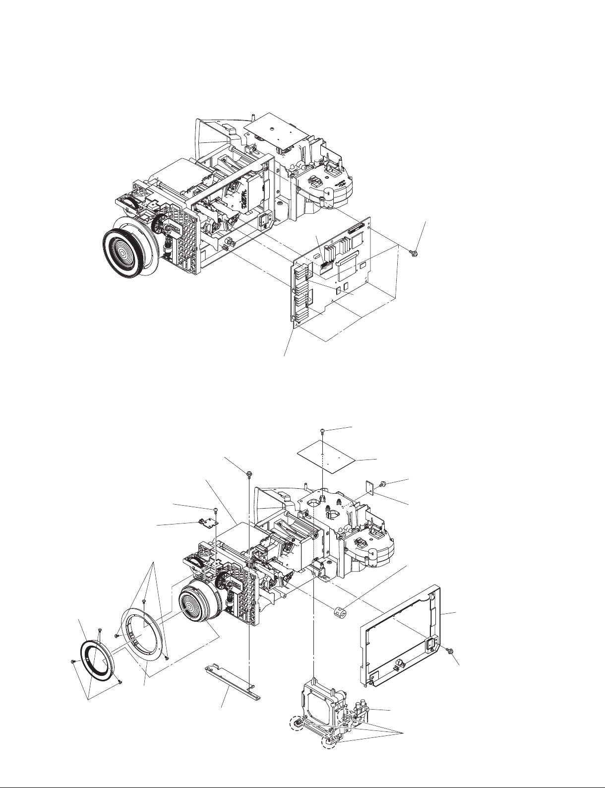
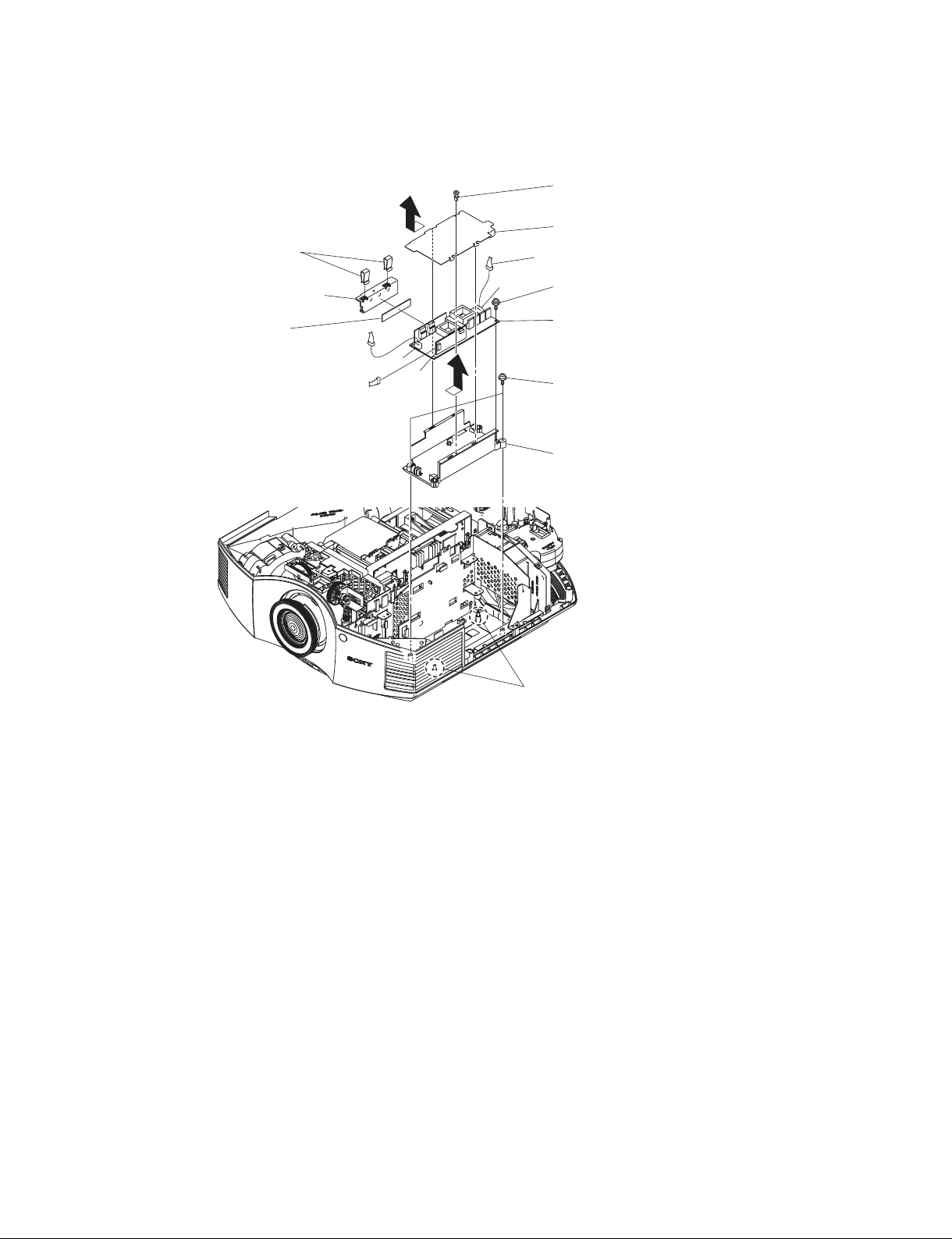
1-3-2. HB Board and TL Board
1 Screw
(BVTP3 x 8)
TL board
CN20
2 HB board
1-3-3. Front Cover Assembly
When removing the front cover
assembly, shift the lens so as to
remove the front cover assembly
smoothly by rotating the dial
indicated in the figure.
3 Front panel assembly
4 TL board
CN60
3 Screw
(BVTP3 x 8)
Dial
1-6 (E)
2 Four screws
(BVTP3 x 12)
1 Lens cap
VPL-HW40ES
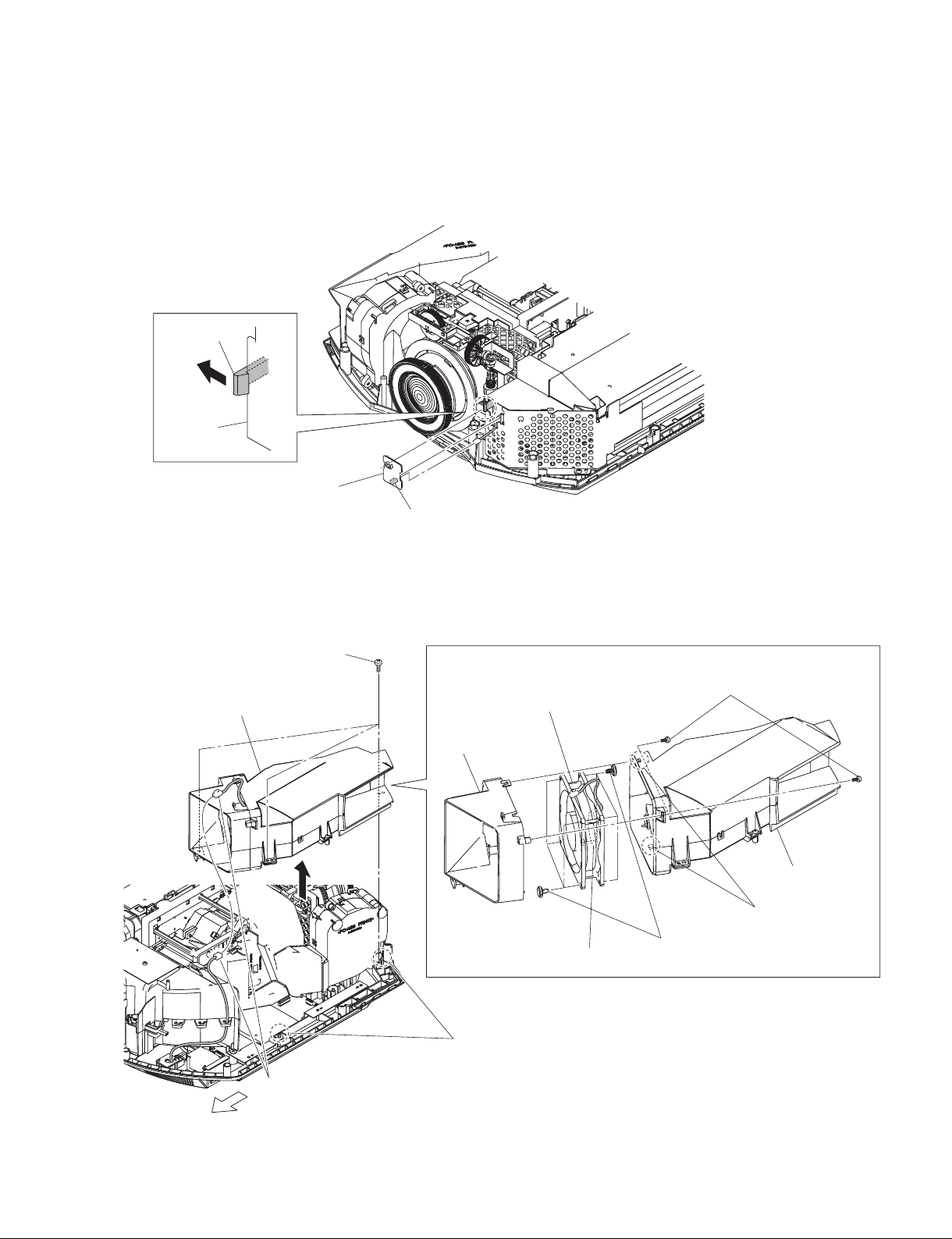
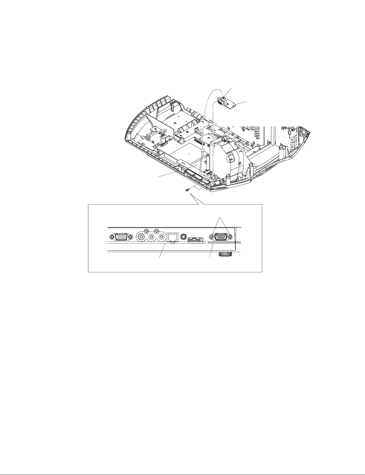
1-3-4. NF Board
1 Hook
NF board
2 NF board
CN30
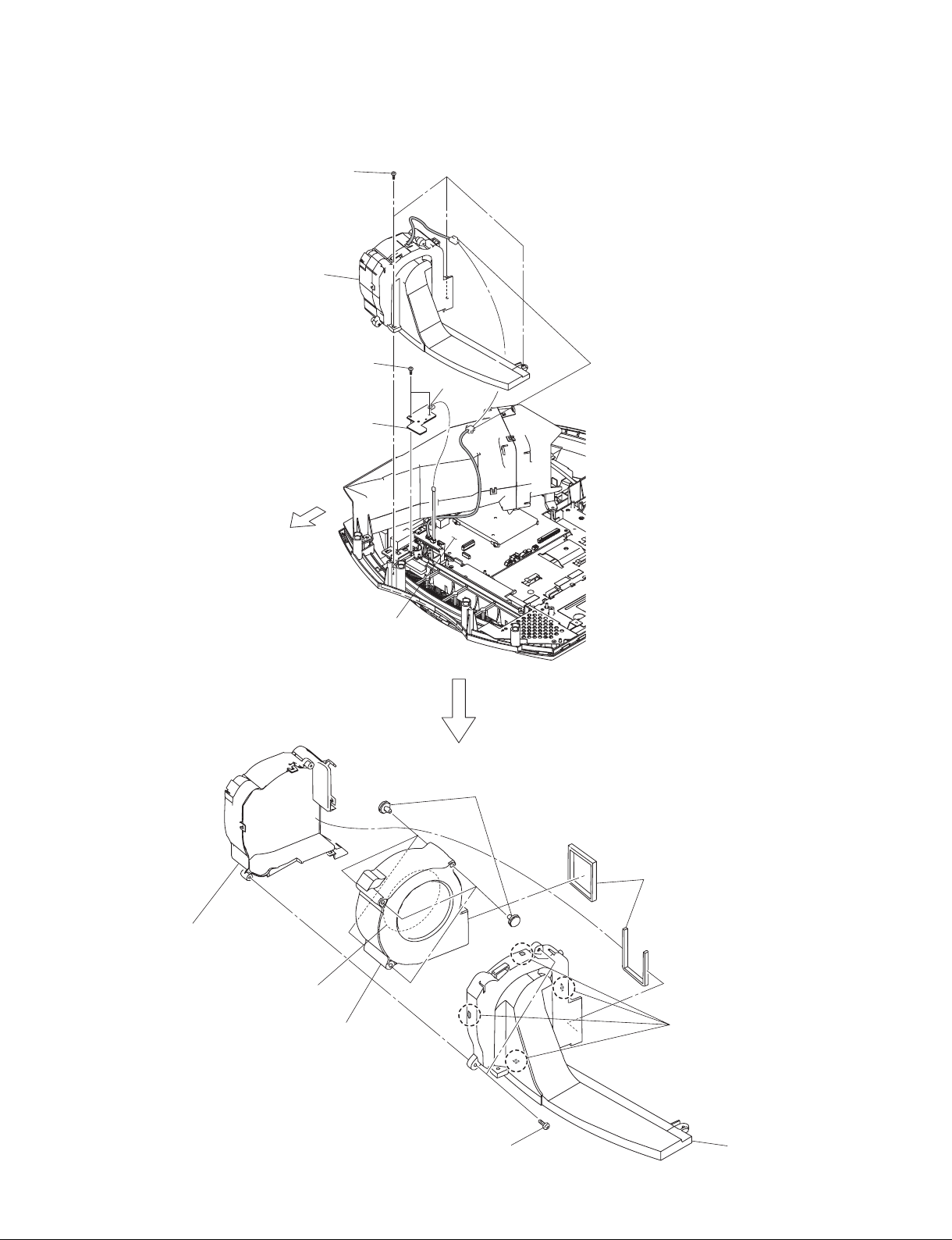
1-3-5. DC Fan (EX)
2 Three screws
4 Remove the DC fan (EX) block
in the direction of the arrow.
(BVTP3 x 12)
7 Fan duct
(EX)
3 Two dowels
0 DC fan (EX)
Label side
5 Two screws
(BVTP3 x 12)
8 Top duct (EX),
bottom duct (EX)
6 Two hooks
9 Eight fan dampers
VPL-HW40ES
1 Fan connector
Front
1-7 (E)
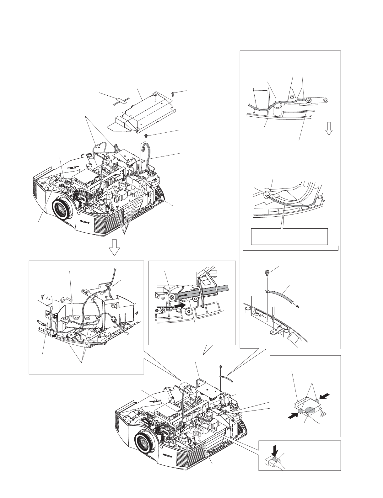
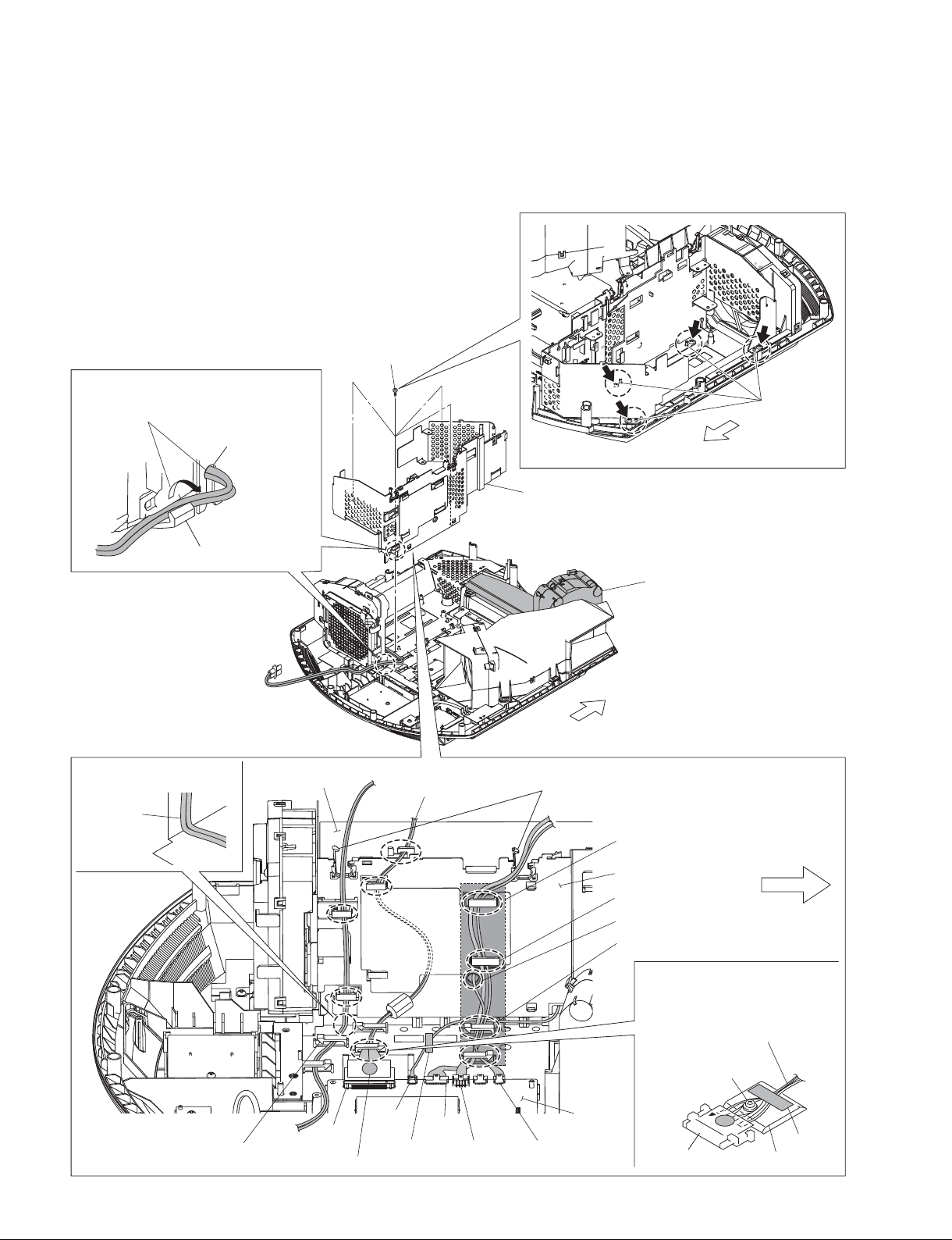
1-3-6. C Board-1
t When removing the C board, perform the procedure in Sections
1-3-6 to 1-3-8.
1 Ta p e
3 Shield (PW)
2 Four screws
(PSW3 x 8)
The lug terminal should not
protrude exceeding the chassis.
Optical unit
7 Two fan connectors
HB board
CN20
Harness
Fuse connector assembly
6 Six hooks
4 Two screws
(BVWHTP3 x 12)
5 Lamp power
connector assembly
0 Loosen screw.
Front side
Bottom cover
assembly
When installing the GND wire harness,
insert the GND wire harness in between
the optical unit and the bottom cover
assembly.
Chassis
Pull the GND harness front to
give tension.
8 Screw
(PSW3 x 8)
9 GND wire
harness
TL board
CN60
1-8 (E)
!= Three harnesses
C board
CN1000
!- Remove the fuse connector
assembly in the direction of the
arrow.
Fuse connector assembly
!\ Harness
To the chassis.
!] Lead with connector
(LVDS)
1-3-7. C Board-2 and U Board
3 Front cover assembly
1 Lens cap
Note in operation:
Do not damage the harnesses.
4 Four screws
(PSW4 x 16)
2 Four screws
(BVTP3 x 12)
CN70
6 Optical unit block (C board)
7 Screw
(BVTP3 x 12)
8 U board
5 Two dowels
Place the harness at a right
angle as shown in the figure.
Harness
GA board
CN301
Marking is printed on the top.
Lead with connector (LVDS)
CN600
CN602
CN400
CN1001
QA board
When installing the harness,
the harness should not protrude
exceeding the shaded area.
G board holder block
Front side
Hooks of plate clamp
Hooks of bottom cover
assembly
Harness of the lead with connector
(LVDS) should not override on top
of the chassis screw.
Lead with connector
(LVDS)
Chassis screw
CN301
Chassis
Tape
VPL-HW40ES
1-9 (E)
1-3-8. C Board-3
CN9000
2 C board
1 Five screws
(PSW3 x 8)
CN9500
CN8000
1-3-9. Optical Unit Assembly
!= Screw
(PSW4 x 16)
!, Optical unit assembly
5 Screw
(BVTP3 x 8)
6 HB board
!] Three tapping screws
(1.7 x 4)
!; Focus ring
assembly
!' Zoom ring assembly
!\ Three tapping screws
(1.7 x 4)
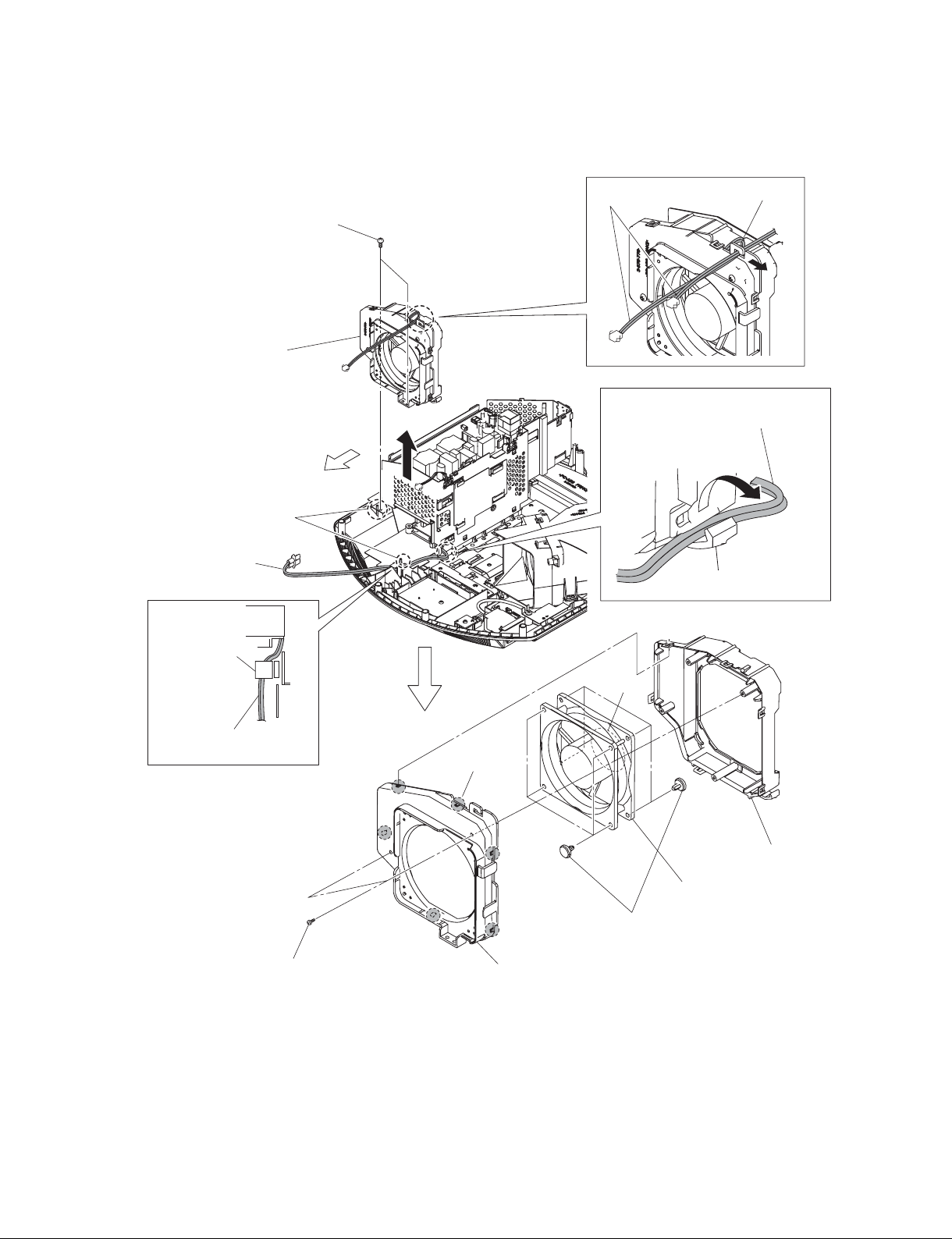
1-3-10. DC Fan
3 Two screws
(BVTP3 x 12)
5 Remove the DC fan block
in the direction of the
arrow B.
Front side
4 Two dowels
Lamp power connector
assembly
B
Two fan harnesses
1 Remove the lamp power connector
assembly in the direction of the
arrow A.
2 Hook
A
Hook
Chassis
Lamp power connector
assembly
6 Two screws
(BVTP3 x 12)
Label side
7 Six hooks
8 Fan bracket
(F) (CH)
!- DC fan
0 Eight fan dampers
9 Fan bracket (R) (CH)
VPL-HW40ES
1-11 (E)
1-3-11. GA Board
1 Ta p e
Fuse connector assembly
CN102
CN103
2 Four screws
(PSW3 x 8)
3 Shield (PW)
CN101
4 GA board
CN104
CN105
5 Shield (PWG)
1-12 (E)
VPL-HW40ES
1-3-12. GB Board
1 Four screws
(PSW3 x 8)
2 Shield (GB)
When removing the GB board, remove it in the
way that the GB board should not contact with
the metal plate of the G board holder.
3 GB board
CN301
CN302
CN303
CN201
CN202
CN203
4 Shield (BLT)
G board holder block
VPL-HW40ES
1-13 (E)
1-3-13. Power Supply Unit
8 Two clips (BA)
9 Heat sink (BA)
0 Sheet (BA)
X1
X2
1 Rivet
2 Sheet (BLT)
Lamp power connector assembly
X3
6 Screws
(PSW3 x 8)
7 Power supply unit
3 Two screws
(BVWHTP3 x 12)
4 Holder (BLT)
5 Two dowels
1-14 (E)
VPL-HW40ES
1-3-14. QB Board
CN91
2 QB board
QA board
1 Two hexagon screws
(There is a height difference.)
QA board QB board
VPL-HW40ES
1-15 (E)
1-3-15. DC Fan and V Board-1
n
When removing the V board, perform the procedure in Sections 1-3-15 and 1-3-16.
5 Remove the lamp power connector
assembly from the hook of fan (CH)
bracket and hole of the plate clamp.
Hole of plate clamp
Hook of fan (CH) bracket
Place the harness at a right
angle as shown in the figure.
Harness
4 Four screws
(BVTP3 x 12)
GA board
A
Lead with connector
(LVDS)
A
A
Front side
7 G board holder block
DC fan block
Front side
1 Open the two edge clamps
When installing the harness,
the harness should not protrude
exceeding the shaded area.
G board holder block
Hook of plate clamp
3 Pull out the harness from the hole.
2 Remove the harness from the eight
hooks.
Harness of the lead with connector
(LVDS) should not override on top
of the chassis screw.
A
A
6 Four
dowels
Front side
Hook of bottom cover assembly
1-16 (E)
CN301
CN600
Marking is printed on the top.
Ta pe
CN602
CN400
CN1001
QA board
Lead with connector
(LVDS)
Chassis screw
CN301
Ta pe
Chassis
VPL-HW40ES
1-3-16. DC Fan and V Board-2
2 Three screws
(BVTP3 x 12)
3 DC fan block
4 Two screws
(BVTP3 x 12)
5 V board
Front side
1 Two fan connectors
CN80
9 Fan cover
(84C)
Label side
!= DC fan
QA board
!- Six fan dampers
7 Two sirocco cushions
8 Four hooks
VPL-HW40ES
6 Two screws
(BVTP3 x 12)
0 Fan cover
(84I)
1-17 (E)

1-3-17. QA Board
Place the harness at a right
angle as shown in the figure.
Harness
GA board
Lead wire with connector
(LVDS)
When installing the harness,
the harness should not protrude
exceeding the shaded area.
Marking is printed on the top.
Lead wire with connector
(LVDS)
CN600
CN301
Marking is printed on the top.
CN600
CN301
CN602
Ta pe
CN400
CN602
CN400
CN1001
CN1001
CN702
CN800
G board holder block
Hooks of plate clamp
Hooks of bottom cover assembly
Harness of the lead with connector
(LVDS) should not override on top
of the chassis screw.
Lead with connector
(LVDS)
Chassis screw
QA board
CN301
1 Four screws
(PSW3 x 8)
CN701
Front side
Ta pe
Chassis
QA board
1-18 (E)
6 Remove the QA board
in the direction of the
arrow D.
432
Two SP4-40 UNC screws (No height difference)
CN703
CN801
QB board
D
Front side
5 Two dowels
2 Two screws
(BVTP3 x 12)
3 Two SP4-40 UNC screws
(No height difference)
4 Two screws
(PSW3 x 8)
VPL-HW40ES
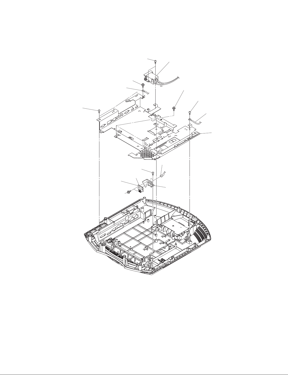
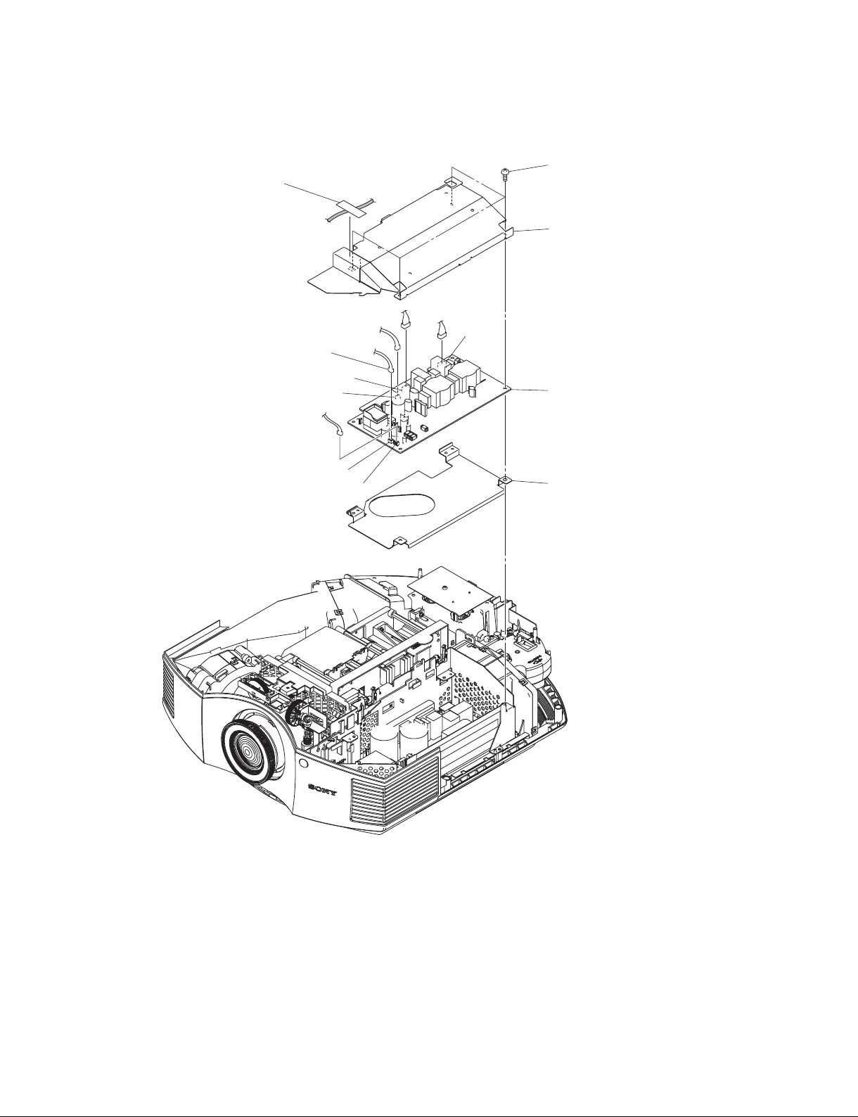
1-3-18. EM Board
3 Two screws
1 Screw
(PSW4 x 8)
(BVTP3 x 12)
4 AC inlet
8 Three screws
(BVTP3 x 12)
2 Ground wire
!- Two screws
(BVTP3 x 12)
!] EM board
1-4. Optional Fixtures
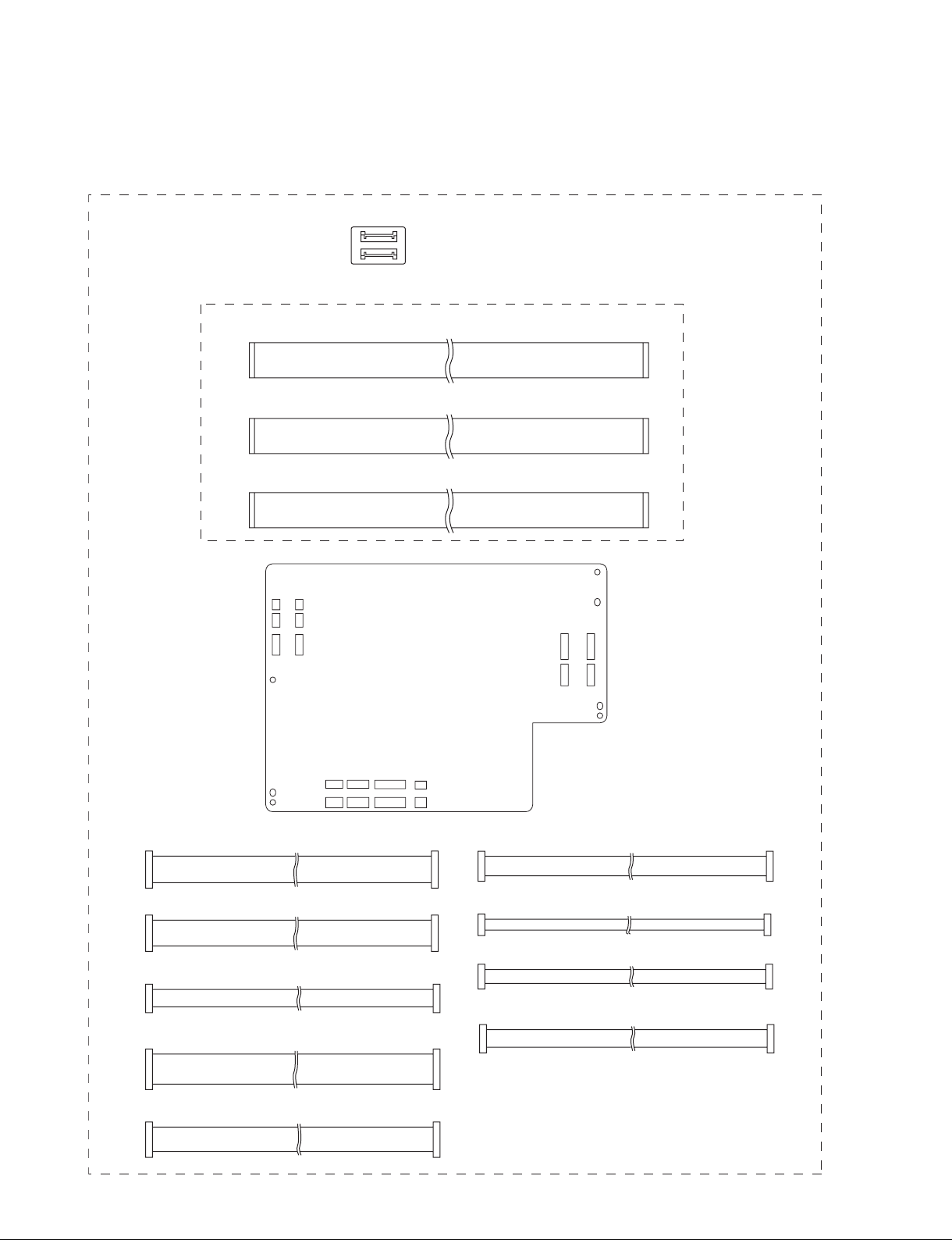
1-4-1. Extension Boards and Extension Cables
X kit assembly (Part No. A-1848-223-A)
The panel extension cable for R, G and B are common.
I-1 PANEL EXTENSION CABLE (80P)
I-2 PANEL EXTENSION CABLE (80P)
I-3 PANEL EXTENSION CABLE (80P)
CJ board x 3
A CONNECTOR ASSY, JST SVC 9P
B CONNECTOR ASSY, MOLEX SVC 10P
C CONNECTOR ASSY, MOLEX SVC 5P
D CONNECTOR ASSY, MOLEX SVC 15P
E CONNECTOR ASSY, JST SVC 4P
XQA board
F CONNECTOR ASSY, MOLEX SVC 9P
G CONNECTOR ASSY, JST SVC 3P
H CONNECTOR ASSY, MOLEX SVC 4P
J CONNECTOR ASSY, JST SVC 6P
1-20 (E)
VPL-HW40ES
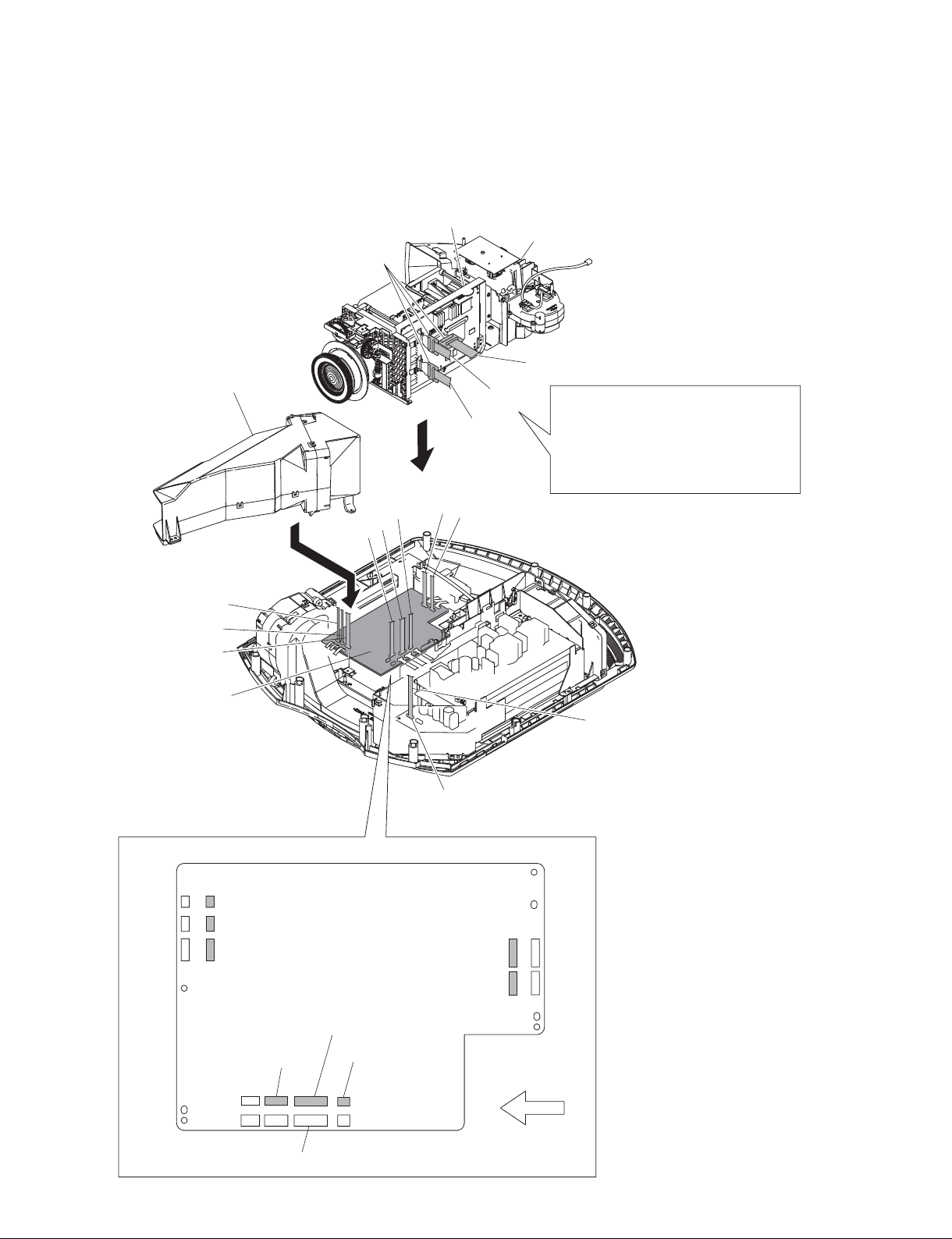
1-4-2. Connection
n
Secure the XQA board to the main unit with the two screws.
C board holder
CJ board x 3
DC fan (EX) block
I-1
A
B
E
D
C
Optical unit block
I-2
I-3
n
Do not pull or stress the 80P flexible card
wire coming from the panel on the optical
unit block.
Doing so may displace the panel and
deteriorate image quality.
CN800
CN703
H
G
F
XQA board
CN1705 HCN705
CN1800 G
CN1703 F
CN1401 E
XQA board
CN1602 D
CN1605 C
GB board
CN301
CN1801 A
CN1704 B
CN801
CN704
Front side
J
A JST service connector assembly (9P)
B MOLEX service connector assembly (10P)
C MOLEX service connector assembly (5P)
D MOLEX service connector assembly (15P)
E JST service connector assembly (4P)
F MOLEX service connector assembly (9P)
G JST service connector assembly (3P)
H MOLEX service connector assembly (4P)
I-1 Panel extension cable (80P)
I-2 Panel extension cable (80P)
I-3 Panel extension cable (80P)
J JST service connector assembly (6P)
VPL-HW40ES
CN401
CN602
CN605
1-21 (E)
n After the connecting with the C board, QA board, and XQA board, place the C board and QA
board on the insulator and then operate.
CN701
H
CN800
G
CN702
F
QA board
CN801
CN703
A
B
CN602
CN400CN1001
Harness from the EM-11 board
HA board
CN11
XQA board
CN600
E D C
QA board
H
G
F
D
Front side
E
Fan connector
A
B
Lead wire with connector (LVDS)
CN1000
J
CN9500
CN8000
CN2000
I-3
CN9000
C board
I-2
I-1
Lamp power connector assembly
Two fan connectors
CN800
CN703
1-22 (E)
CN1705 HCN705
CN1800 G
CN1703 F
CN1401 E
CN401
CN602
XQA board
CN1602 D
CN1605 C
CN605
GB board
CN301
CN1801 A
CN1704 B
CN801
CN704
Front side
C
Fuse connector assembly
CJ board x 3
A JST service connector assembly (9P)
B MOLEX service connector assembly (10P)
C MOLEX service connector assembly (5P)
D MOLEX service connector assembly (15P)
E JST service connector assembly (4P)
F MOLEX service connector assembly (9P)
G JST service connector assembly (3P)
H MOLEX service connector assembly (4P)
I-1 Panel extension cable (80P)
I-2 Panel extension cable (80P)
I-3 Panel extension cable (80P)
J JST service connector assembly (6P)
VPL-HW40ES
 Loading...