

Sony VPL-ES1, RM-PJ2 User Manual

DATA PROJECTOR
VPL-ES1
REMOTE COMMANDER
RM-PJ2
SERVICE MANUAL
1st Edition

! WARNING
This manual is intended for qualified service personnel only.
To reduce the risk of electric shock, fire or injury, do not perform any servicing other than that
contained in the operating instructions unless you are qualified to do so. Refer all servicing to
qualified service personnel.
! WARNUNG
Die Anleitung ist nur für qualifiziertes Fachpersonal bestimmt.
Alle Wartungsarbeiten dürfen nur von qualifiziertem Fachpersonal ausgeführt werden. Um die
Gefahr eines elektrischen Schlages, Feuergefahr und Verletzungen zu vermeiden, sind bei
Wartungsarbeiten strikt die Angaben in der Anleitung zu befolgen. Andere als die angegeben
Wartungsarbeiten dürfen nur von Personen ausgeführt werden, die eine spezielle Befähigung
dazu besitzen.
! AVERTISSEMENT
Ce manual est destiné uniquement aux personnes compétentes en charge de l’entretien. Afin
de réduire les risques de décharge électrique, d’incendie ou de blessure n’effectuer que les
réparations indiquées dans le mode d’emploi à moins d’être qualifié pour en effectuer d’autres.
Pour toute réparation faire appel à une personne compétente uniquement.
WARNING!!
AN INSULATED TRANSFORMER SHOULD BE USED DURING
ANY SERVICE TO AVOID POSSIBLE SHOCK HAZARD, BECAUSE OF LIVE CHASSIS.
THE CHASSIS OF THIS RECEIVER IS DIRECTLY CONNECTED
TO THE AC POWER LINE.
SAFETY-RELATED COMPONENT WARNING !!
COMPONENTS IDENTIFIED BY A
DIAGRAMS, EXPLODED VIEWS AND IN THE PARTS LIST ARE
CRITICAL TO SAFE OPERATION. REPLACE THESE COMPONENTS WITH SONY PARTS WHOSE PART NUMBERS APPEAR
AS SHOWN IN THIS MANUAL OR IN SUPPLEMENTS PUBLISHED BY SONY. CIRCUIT ADJUSTMENTS THAT ARE CRITICAL TO SAFE OPERATION ARE IDENTIFIED IN THIS MANUAL.
FOLLOW THESE PROCEDURES WHENEVER CRITICAL COMPONENTS ARE REPLACED OR IMPROPER OPERATION IS
SUSPECTED.
!!
! MARK ON THE SCHEMATIC
!!
ATTENTION!!
AFIN D’ÉVITER TOUT RISQUE D’ÉLECTROCUTION
PROVENANT D’UN CHÂSSIS SOUS TENSION, UN
TRANSFORMATEUR D’ISOLEMENT DOIT ETRE UTILISÉ LORS
DE TOUT DÉPANNAGE.
LE CHÂSSIS DE CE RÉCEPTEUR EST DIRECTEMENT
RACCORDÉ Á L’ALIMENTATION SECTEUR.
ATTENTION AUX COMPOSANTS RELATIFS Á LA
LES COMPOSANTS IDENTIFIÉS PAR UNE MAPQUE
LES SCHÉMAS DE PRINCIPE, LES VUES EXPLOSÉES ET LES
LISTES DE PIECES SONT D’UNE IMPORTANCE CRITIQUE
POUR LA SÉCURITÉ DU FONCTIONNEMENT. NE LES
REMPLACER QUE PAR DES COMPOSANTS SONY DONT LE
NUMÉRO DE PIÈCE EST INDIQUÉ DANS LE PRÉSENT MANUEL
OU DANS DES SUPPLÉMENTS PUBLIÉS PAR SONY. LES
RÉGLAGES DE CIRCUIT DONT L’IMPORTANCE EST CRITIQUE
POUR LA SÉCURITÉ DU FONCTIONNEMENT SONT
IDENTIFIÉS DANS LE PRÉSENT MANUEL. SUIVRE CES
PROCÉDURES LORS DE CHAQUE REMPLACEMENT DE
COMPOSANTS CRITIQUES, OU LORSQU’UN MAUVAIS
FONCTIONNEMENT EST SUSPECTÉ.
SÉCURITÉ!!
!!
! SUR
!!
VPL-ES1

For the customers in the Netherlands
Voor de klanten in Nederland
Hoe u de batterijen moet verwijderen, leest u in de tekst
van deze handleiding.
Gooi de batterij niet weg maar lever deze in als klein
chemisch afval (KCA).
Für Kunden in Deutschland
Entsorgungshinweis: Bitte werfen Sie nur entladene
Batterien in die Sammelboxen beim Handel oder den
Kommunen. Entladen sind Batterien in der Regel dann,
wenn das Gerät abschaltet und signalisiert “Batterie
leer” oder nach längerer Gebrauchsdauer der Batterien
“nicht mehr einwandfrei funktioniert”. Um
sicherzugehen, kleben Sie die Batteriepole z.B. mit
einem Klebestreifen ab oder geben Sie die Batterien
einzeln in einen Plastikbeutel.
VPL-ES1


Table of Contents
1. Service Overview
1-1. Appearance Figure ...................................................................................... 1-1
1-2. Board Locations .......................................................................................... 1-1
1-3. Disassembly ................................................................................................ 1-2
1-3-1. Top Panel Assembly .................................................................. 1-2
1-3-2. H Board ...................................................................................... 1-2
1-3-3. C Board ...................................................................................... 1-3
1-3-4. Lens Gear ................................................................................... 1-4
1-3-5. Fan Holder .................................................................................. 1-4
1-3-6. D.C. Fan (60mm) and D.C. Fan (70mm) .................................. 1-5
1-3-7. Lamp House ............................................................................... 1-5
1-3-8. Optics Block Assembly .............................................................. 1-6
1-3-9. Prism Block Assembly ...............................................................1-6
1-3-10. Incidence Polarizer (R), (G), (B) ................................................1-7
1-3-11. Side Panel Assembly-1 .............................................................. 1-8
1-3-12. Side Panel Assembly-2 .............................................................. 1-9
1-3-13. G Board .................................................................................... 1-10
1-3-14. Lamp Power Supply .................................................................1-10
1-3-15. D.C. Fan (Sirocco/For Lamp) .................................................. 1-11
1-3-16. D.C. Fan (Sirocco) ................................................................... 1-12
1-3-17. Adjuster Block Assembly ........................................................ 1-13
1-4. Warning on Power Connection ................................................................. 1-14
2. Electrical Adjustments
2-1. Preparation .................................................................................................. 2-1
2-1-1. Required Equipment ................................................................... 2-1
2-1-2. Opt Unit Adjustment .................................................................. 2-1
2-1-3. How to Enter the Factory Mode .................................................2-2
2-2. V COM Adjustment .................................................................................... 2-2
2-3. Initial Values of Adjustment Items ............................................................. 2-3
2-4. Service Know-How .....................................................................................2-8
2-4-1. When the S Prism Block Is Replaced ........................................ 2-8
2-4-2. When the C Board Is Replaced .................................................. 2-8
2-5. White Balance Adjustment ......................................................................... 2-9
2-5-1. HIGH Mode of INPUT-A .......................................................... 2-9
2-5-2. LOW Mode of INPUT-A ........................................................... 2-9
2-5-3. HIGH Mode of VIDEO .............................................................. 2-9
2-5-4. LOW Mode of VIDEO ............................................................... 2-9
2-6. Memory Structure ..................................................................................... 2-10
3. Semiconductors................................................................................. 3-1
VPL-ES1
1

4. Spare Parts
4-1. Notes on Repair Parts .................................................................................. 4-1
4-2. Exploded Views .......................................................................................... 4-2
4-3. Electrical Parts List ..................................................................................... 4-6
5. Block Diagrams
C ............................................................................................................................. 5-1
G, H, V, L, NR ....................................................................................................... 5-2
6. Diagrams
6-1. Frame Wiring .............................................................................................. 6-2
Frame Wiring ............................................................................................6-2
6-2. Schematic Diagrams and Board Layouts .................................................... 6-3
Schematic Diagrams
Q ................................................................................................................ 6-3
C (1/10) ..................................................................................................... 6-6
C (2/10) ..................................................................................................... 6-7
C (3/10) ..................................................................................................... 6-8
C (4/10) ..................................................................................................... 6-9
C (5/10) ................................................................................................... 6-10
C (6/10) ................................................................................................... 6-11
C (7/10) ................................................................................................... 6-12
C (8/10) ................................................................................................... 6-13
C (9/10) ................................................................................................... 6-14
C (10/10) ................................................................................................. 6-15
V .............................................................................................................. 6-14
H .............................................................................................................. 6-18
L .............................................................................................................. 6-19
NR ...........................................................................................................6-19
G (1/2) .....................................................................................................6-21
G (2/2) .....................................................................................................6-22
Board Layouts
Q ................................................................................................................ 6-3
C ................................................................................................................6-4
V .............................................................................................................. 6-14
H .............................................................................................................. 6-18
L .............................................................................................................. 6-19
NR ...........................................................................................................6-19
G .............................................................................................................. 6-20
2
VPL-ES1

1-1. Appearance Figure
Section 1
Service Overview
VPL-ES1 RM-PJ2
1-2. Board Locations
Q
C
V
H
NR
L
G
Lamp power supply
VPL-ES1
1-1
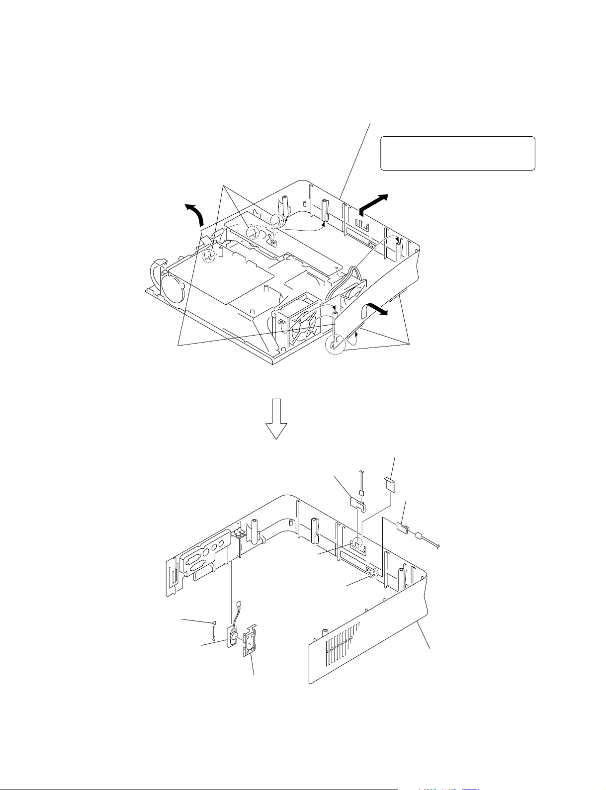
1-3. Disassembly
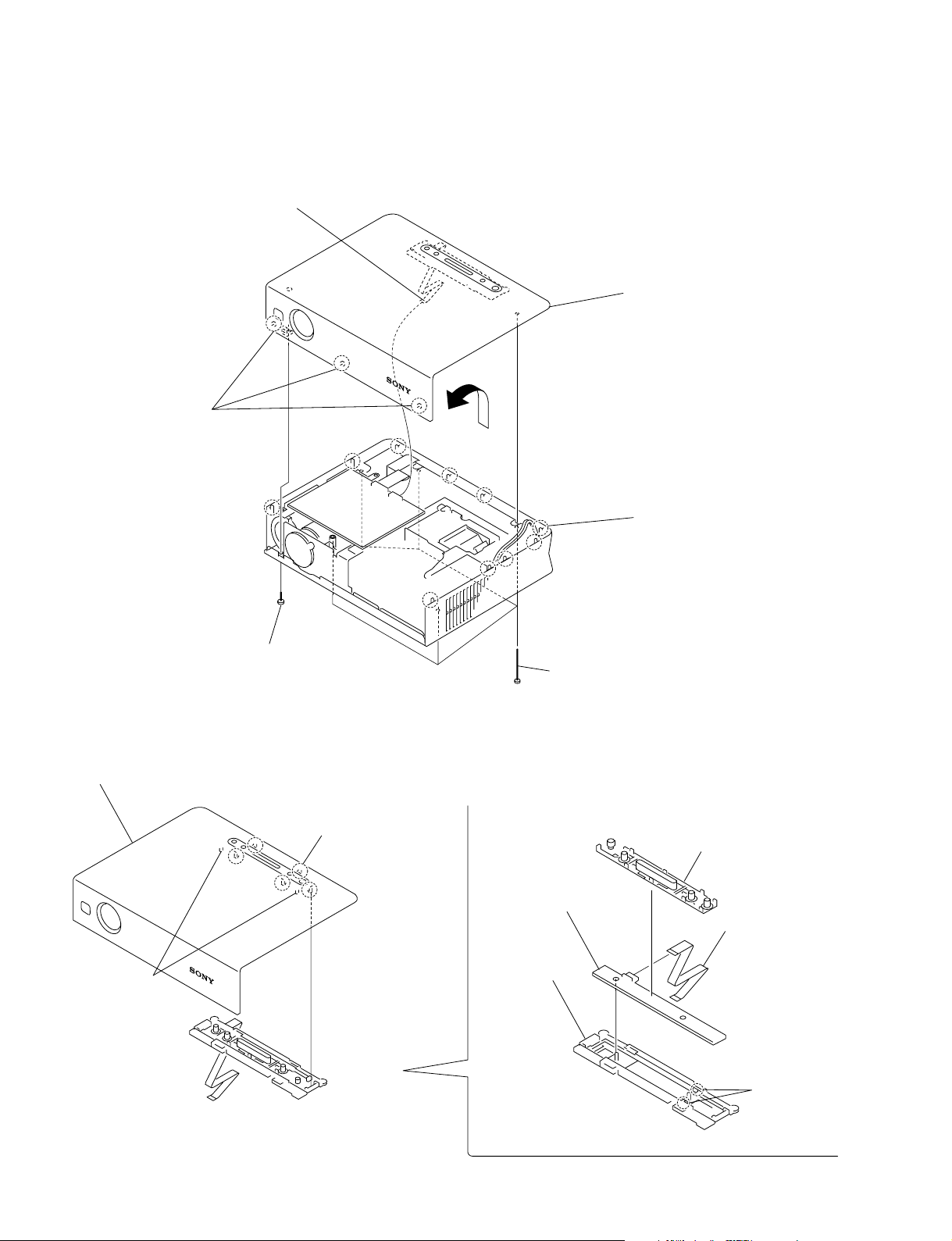
1-3-1. Top Panel Assembly
5 Flat connector assembly
(CN805)
3 Three claws
6 Remove the top panel assembly
in the direction of the arrow.
C board
2 Screw
(+B 3 x 6)
1-3-2. H Board
. Remove the top panel assembly. (Refer to 1-3-1.)
3 Top panel
1 Five claws
2 Two dowels
4 Ten claws
1 Five special shafts
(+BV 3 x 70)
7 Button (H)
8 H board
4 Flat connector
assembly
CN10
6 Holder (H)
1-2
5 Two claws
VPL-ES1
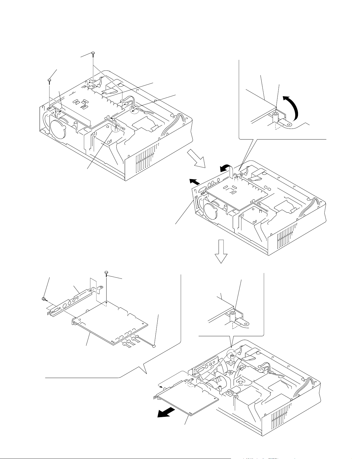
1-3-3. C Board
3 Four screws
(+B 3 x 6)
CN904
2 Remove the fuse
connector assembly
CN906
CN601
CN812
CN651
CN804
CN501
CN802
CN807
CN810
C board
5 Remove the C board
in the direction of the arrow B.
Side panel shaft
1 Remove the harneses
B
B
A
8 Two screws
9 Bracket (C)
!- C board
CN905
4 Open the side panel assembly in the
direction of the arrow A.
7 Screw
(+B 3 x 6)
0 Fuse connector
assembly
CN806
CN811
CN809
Side panel shaft
C board
VPL-ES1
C
6 Remove the C board
in the direction of the arrow C.
1-3

1-3-4. Lens Gear
. Remove the C board. (Refer to 1-3-3.)
ZOOM/FOCUS ZOOM/FOCUS
Engage the gears.
Lens gear
Lens
2 Open the side panel assembly in the
direction of the arrow A.
A
B
3 Two dowels
C board
4 Remove the Iens gear
1 Screw
(+B 3 x 6)
in the direction of the arrow B.
1-3-5. Fan Holder
1 Two screws
(+BVTP 3 x 10)
A
5 Remove the fan holder
while taking care so that it must
not be caught by other parts.
4 Dowel
3 Remove the four claws
in the direction of the arrow B.
Fan holder
B
Side panel assembly
1-4
2 Remove the side panel assembly
in the direction of the arrow A.
VPL-ES1
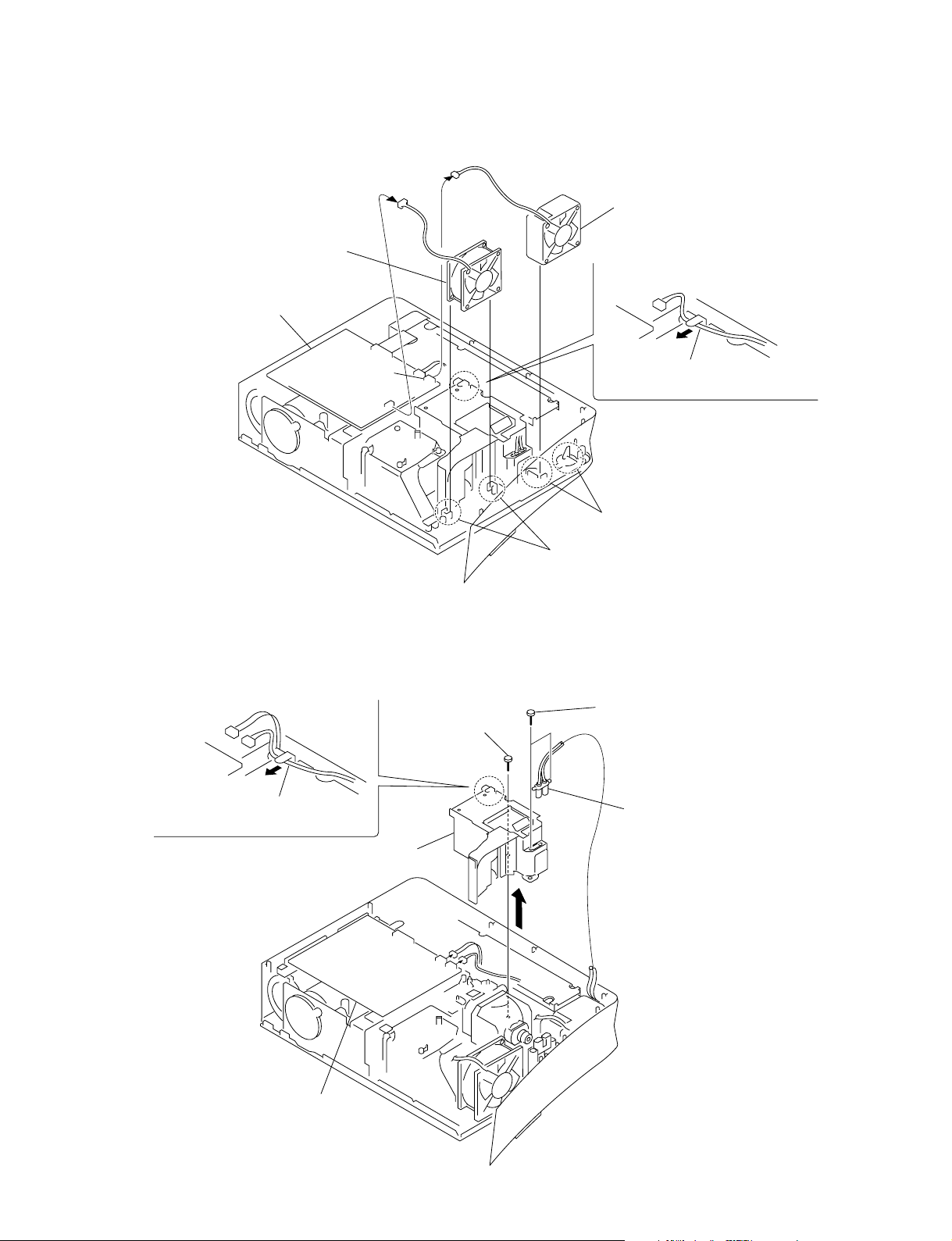
1-3-6. D.C. Fan (60mm) and D.C. Fan (70mm)
. Remove the fan holder. (Refer to 1-3-5.)
2 D.C. fan (70mm)
C board
5 D.C. fan (60mm)
CN810
CN811
1-3-7. Lamp House
. Remove the fan holder. (Refer to 1-3-5.)
1 Remove the harneses
4 Screw
(+BTP 3 x 10)
3 Remove the harneses
4 Two grooves
1 Two grooves
2 Two screws
(+BTP 3 x 10)
3 Lamp power supply
VPL-ES1
5 Lamp house
C board
CN807
CN810
1-5
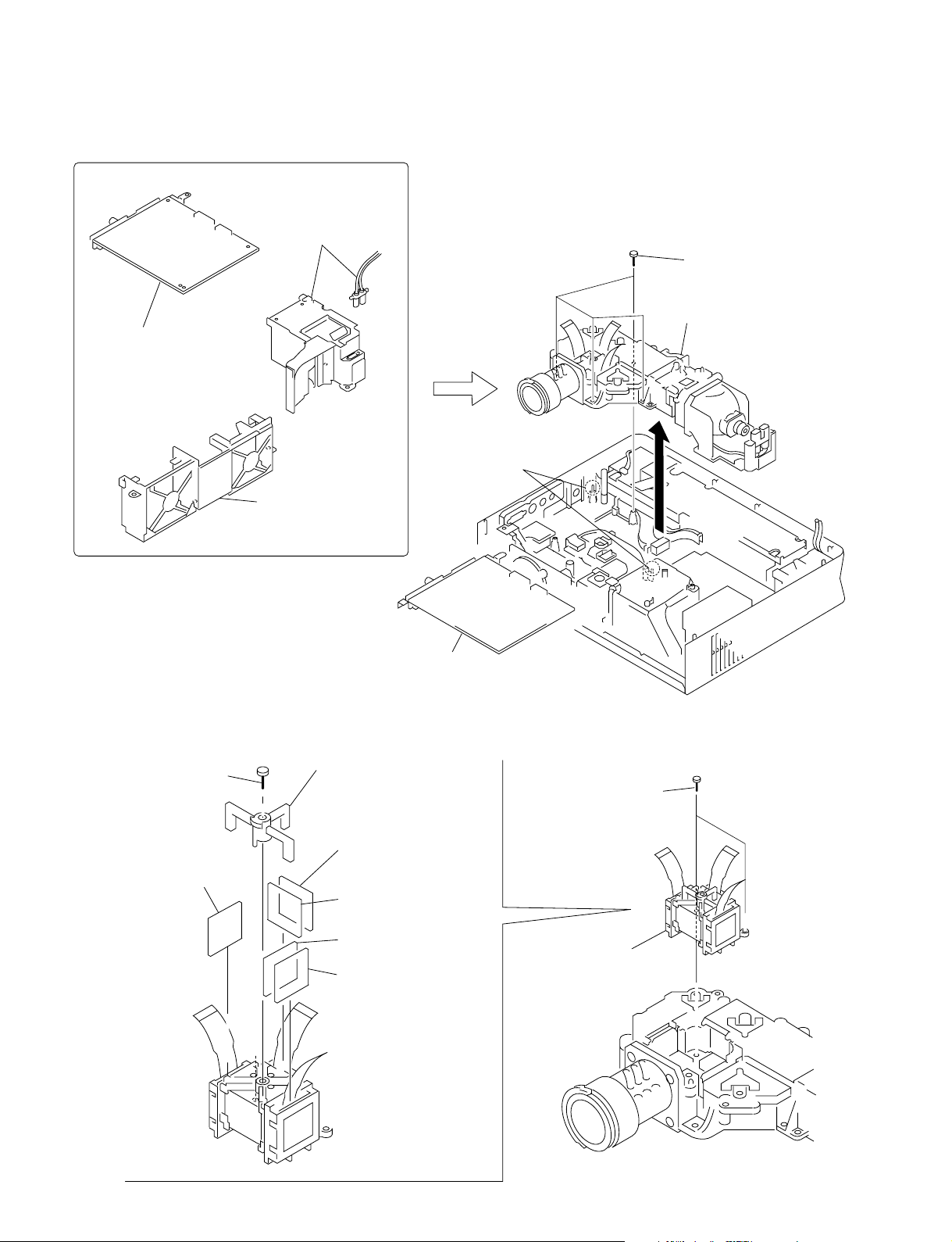
1-3-8. Optics Block Assembly
. To remove the optics block assembly, remove the related parts beforehand.
3 Lamp house
• Remove the lamp house.
(Refer to 1-3-7.)
1 C board
• Remove the C board.
(Refer to 1-3-3.)
5 Two dowels
2 Fan holder
• Remove the fan holder.
(Refer to 1-3-5.)
4 Four screws
(+BTP 3 x 10)
6 Optics block assembly
1-3-9. Prism Block Assembly
. Remove the optics block assembly. (Refer to 1-3-8.)
3 Screw
(+PTP 2 x 8)
5 Radiation polarizer
(R) assembly
4 Polarizer retainer
6 Pre radiation polarizer
(G) assembly
7 Radiation polarizer
(G) assembly
9 Radiation polarizer
(B) assembly
8 Pre radiation polarizer
(B) assembly
C board
1 Two precision screws
(+B 2 x 5)
2 Prism block assembly
1-6
VPL-ES1

1-3-10. Incidence Polarizer (R), (G), (B)
. Remove the optics unit assembly. (Refer to 1-3-8.)
. Remove the prism block assembly. (Refer to 1-3-9.)
1 Six screws
(+BTP 3 x 10)
3 Incidence polarizer (R) assembly
2 Unit cover
4 Incidence polarizer (G) assembly
5 Incidence polarizer (B) assembly
VPL-ES1
1-7

1-3-11. Side Panel Assembly-1
2 Four screws
(+B 3 x 6)
CN906
CN812
CN651
CN804
CN501
CN802
CN807
CN810
CN601
C board
4 Remove the C board
in the direction of the arrow B.
Side panel shaft
1 Remove the harneses
B
Cover (B2)
Cover (B)
A
3 Open the side panel assembly in the
direction of the arrow A.
Cover (G)
B
C board
5 Screw
(+B 3 x 6)
6 Cover (G),
Sheet (G)
1-8
Sheet (G)
G board
G board
C board
VPL-ES1
1-3-12. Side Panel Assembly-2
. Remove the C board and cover (G). (Refer to 1-3-11.)
Three claws
B
2 Remove the side panel assembly
in the direction of the arrow C.
Note : Remove the
while taking care so that it must
not be caught by other parts.
C
A
side panel assembly
1
Open the
in the direction of the arrow
side panel assembly
7
Sheet
(
speaker
8
Speaker assembly
)
AB
Three claws
.
3
Sheet
CN01
(NR)
5
L board
CN70
9 Side panel assembly
4
NR board
Claw
Two claws
VPL-ES1
Speaker bracket
6
1-9

1-3-13. G Board
. Remove the cover (G), sheet (G). (Refer to 1-3-11)
1
Flat connector assembly
2
G board
C board
1-3-14. Lamp Power Supply
. Remove the cover (G), sheet (G). (Refer to 1-3-11)
. Remove the G board. (Refer to 1-3-13.)
CN201
CN102
CN101
3 Sheet (B)
C board
1 Two screws
(+BTP 3 x 10)
CN1
CN2
2 Two screws
(+B 3 x 6)
4
Lamp power supply
1-10
VPL-ES1
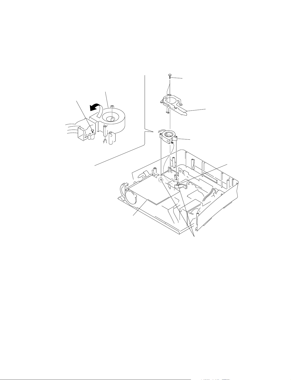
1-3-15. D.C. Fan (Sirocco/For Lamp)
. Remove the side panel assembly-1,2. (Refer to 1-3-11, 12)
. Remove the G board. (Refer to 1-3-13.)
5 Remove the D.C. fan (Sirocco/For lamp)
in the direction of the arrow.
4 Loosen the screw.
1 Two screws
(+BTP 3 x10)
2 Fan bracket
6 D.C. fan (Sirocco/For lamp)
Fan holder
C board
3 Two dowels
VPL-ES1
1-11

1-3-16. D.C. Fan (Sirocco)
CN802
CN806
CN811
CN809
CN905
1 Remove the
fuse connector assembly
2 Three screws
(+BTP 3 x 10)
C board
3 Remove the fan holder
in the direction of the arrow.
4 Fan holder
Dowel
7 D.C. fan (Sirocco)
1-12
5 Remove the
harneses
6 Two dowels
D.C. fan (Sirocco)
VPL-ES1

1-3-17. Adjuster Block Assembly
. To remove the adjuster block assembly, remove the related parts beforehand.
2 Fan holder
1 C board
• Remove the C board.
(Refer to 1-3-3.)
4 Optics block assembly
• Remove the optics block assembly.
(Refer to 1-3-8.)
• Remove the fan holder.
(Refer to 1-3-5.)
3 Lamp house
• Remove the lamp house.
(Refer to 1-3-7.)
7 Dowel
8 Remove the adjuster block assembly
in the direction of the arrow.
5 Three screws
(+BTP 3 x 10)
9 Adjuster block assembly
6 Dowel
VPL-ES1
1-13

1-4. Warning on Power Connection
n
. When a signal other than the preset signals shown above is input, the picture may not appear properly.
. Memory No. 22 shows the interlace signal.
Warning on power connection
Use a proper power cord for your local power supply.
The United States, Continental Europe UK, Ireland, Japan
Canada
Plug type VM0233 290B YP-12A COX-07
Connector type VM0089 386A YC-13B COX-02 VM0310B YC-13
Cord type SJT SJT H05VV-F H05VV-F N13237/CO-228 VCTF
Rated Voltage & Current 10A/125V 10A/125V 10A/250V 10A/250V 10A/250V 7A/125V
Safety approval UL/CSA UL/CSA VDE VDE VDE DENAN
Cord length (max.) 4.5m –
(1) Use an appropriate rating plug which is applied to local regulations.
Australia,
New Zealand
(1) YP332
-
1-14
VPL-ES1

Section 2
Lens projection
Lens gear
Gear alignment portion
Lens gear
Lens gear
Zoom
Focus
Electrical Adjustments
2-1. Preparation
2-1-1. Required Equipment
. NTSC, PAL, SECAM component signal generator
Sony Tektronix TG2000 + AVG1 (option module) +
AWVG1 (option module) or equivalent
. VG (programmable video signal generator)
VG854 or equivalent
. Illuminance meter
n
Allow the warm-up time of 5 minutes after the power is on
before starting the following adjustments.
2-1-2. Opt Unit Adjustment
1. Let the VPL-ES1 show the ALL WHITE screen.
2. Adjust the B-channel illumination adjustment mirror
so that the yellow frame must not appear in any of top,
bottom, right and left of the screen.
3. Tighten the adjustment plate fixing screw using a
torque screwdriver. (Torque 0.19 ±0.03 Nm)
4. Adjust the G-channel illumination adjustment mirror
so that the magenta frame must not appear in any of
top, bottom, right and left of the screen.
5. Tighten the adjustment plate fixing screw using a
torque screwdriver. (Torque 0.19 ±0.03 Nm)
6. Adjust the R-channel illumination adjustment mirror
so that the cyan frame must not appear in any of top,
bottom, right and left of the screen.
7. Tighten the adjustment plate fixing screw using a
torque screwdriver. (Torque 0.19 ±0.03 Nm)
8. Confirm that the illumination range error is within the
allowable range of product specification.
9. Install the VPL-ES1 in the cabinet. Confirm that the
illumination range error is within the allowable range
of product specification after the VPL-ES1 is installed
in the cabinet.
When installing the optical unit in this model, alignment of
the gear tooth position is required. Perform the following
steps.
Procedure
1. Rotate the lens focus and zoom in the fully clockwise
positions. Lock the lens gear in the direction shown in
Fig. 1.
Fig. 1
2. Align the marking position of the lens zoom gear with
the protrusion of the lens gear approximately by visual
observation as shown below.
Engage the gears.
VPL-ES1
Lens gear
Fig. 2 (inside view)
Lens
2-1

Confirmation
Install the side panel and confirm that the portions A and
B of the dial cannot be seen from the opening of the side
panel when the ZOOM and FOCUS are moved to their
very ends.
A
ZOOM FOCUS ZOOM FOCUS
B
Good No good
2-1-3. How to Enter the Factory Mode
1. Confirm that the MENU can be displayed.
2. Close the MENU.
3. Press the keys in the following order : [ENTER] →
[ENTER] → [&] → [ENTER].
The message [Do you want to enter the Factory Mode?
Yes : ↑ No : ↓] appears.
Select [Yes : ↑].
[Supplementary information: How to Exit the
Factory Mode]
Perform the step 3 KEY operation.
The message [Do you want to return to the User Mode?
Yes : ↑ No : ↓] appears.
Select [Yes : ↑].
2-2. V COM Adjustment
1. Connect the VG to the INPUT-A connector. Connect
the FLAT FIELD 100 IRE signal to the input connector. Leave the VPL-ES1 with POWER ON for 10
minutes or longer for aging.
2. Enter the Factory Mode. Enter the Device Adjust
MENU, and then enter the Panel Drive Adjustment
MENU.
3. Connect the SVGA, R-single color, 30 IRE, single-line
ON/OFF signal to the input connector.
4. Enter the P. DRV Adjustment MENU, and then enter
the VCOM R Adjustment screen.
5. Adjust the VCOM R value for minimum flicker.
6. Change the input signal to the SVGA, G-single color,
30 IRE, single-line ON/OFF signal, and connect it to
the input connector.
7. Enter the P. DRV Adjustment MENU, and then enter
the VCOM G Adjustment screen.
8. Adjust the VCOM G value for minimum flicker.
9. Change the input signal to the SVGA, B-single color,
30 IRE, single-line ON/OFF signal, and connect it to
the input connector.
10. Enter the P. DRV Adjustment MENU, and then enter
the VCOM B Adjustment screen.
11. Adjust the VCOM B value for minimum flicker.
12. Store the adjustment value in the memory.
13. Turn over the “Image flip” up side down and repeat
the steps from 1 through 12.
n
In the Factor mode, you can close the lens shutter if you
keep pressing the TILT key even though the lamp lights.
If the machine is left in this state for long hours, the lens
shutter may melt in the worst case. Be sure to confirm that
the lens shutter is not closed when the lamp lights in the
Factory mode.
2-2
VPL-ES1

VPL-ES1
MenuTitle ItemName MemoryName
Remark
Set Memory
Status
Memory
Picture Memory W/B Memory
Video
S Video Input-A Video Computer
Dynamic Standard Dynamic Standard Dynamic Standard High
Low
High
Low
PICTURE SETTING Picture Mode Standard
Adjust Picture...
Contrast 90 80 90 80 90 80
Brightness 40 50 40 50 40 50
Color 50 50 50 50 50 50
Hue 50 50 50 50 50 50
Sharpness High High Middle Middle Middle Middle
Gamma Mode ----Graphics Graphics
Color Temp. Low Low Low Low High High
Volume 30
INPUT SETTING Adjust Signal...
Dot Phase
15
(
*)
H Size *
Shift *
Wide Mode Off Off Off Off Off Off
Scan Conv On On
SET SETTING Smart APA On
Auto Input Search Off
Input-A Signal Sel. Computer
Color System Auto
Power Saving Off
Illumination On
MENU SETTING Status On
Languege English
Menu Position Center
Menu Color White
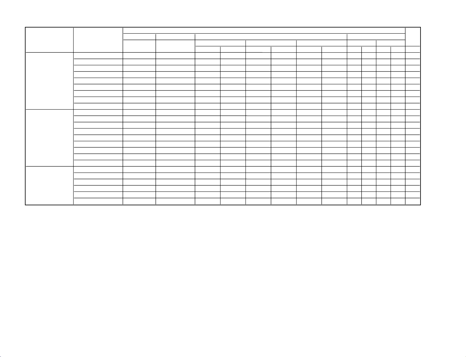
2-3. Initial Values of Adjustment Items
2-3
2-4
MenuTitle ItemName MemoryName
Set Memory Status
Picture Memory W/B Memory
Video
S Video Input-A Video
Computer
Dynamic Standard Dynamic Standard Dynamic Standard High
Low
High
Low
INSTALL SETTING Tilt...
V Keystone Auto
Manual... 0
Image Flip Off
Background Blue
Lamp Mode Standard
High Altitude Off
Security Lock Off
Key Enter x 4
INFORMATION fH
fV
(Memory No.)
(Resolution)
Lamp Timer
ROM Version
SC ROM Version
Operation Timer
Prev. Lamp Timer
W/B SETTING Gain R 155 165 150 150
G 145 120 140 140
B 130 130 150 140
Bias R 130 130 127 127
G 120 120 127 127
B 120 120 127 127
Remark
Display only
Display only
Display only
Display only
Display only
Display only
Display only
Display only
Display only
* : The “Dot Phase E, H Size, Shift H/V and Picture Mode” items in the “INPUT SETTING” menu have their respective initial values for each input signal (PRESET
MEMORY No.).
n
There are some adjustment items that cannot be adjusted, depending on the input signal.
VPL-ES1
 Loading...