

Sony UPA-P100MD, RM-P110 User Manual

3-206-230-11(1)
Digital Captur e
Unit
Remote Contr ol
Unit
User’s Guides
UPA-P100MD
RM-P110
© 2001 Sony Corporation
WARNING
To prevent fire or shock hazard, do not expose the unit to
rain or moisture.
To avoid electrical shock, do not open the cabinet. Refer
servicing to qualified personnel only.
THIS APPARATUS MUST BE EARTHED.
For UPA-P100MD
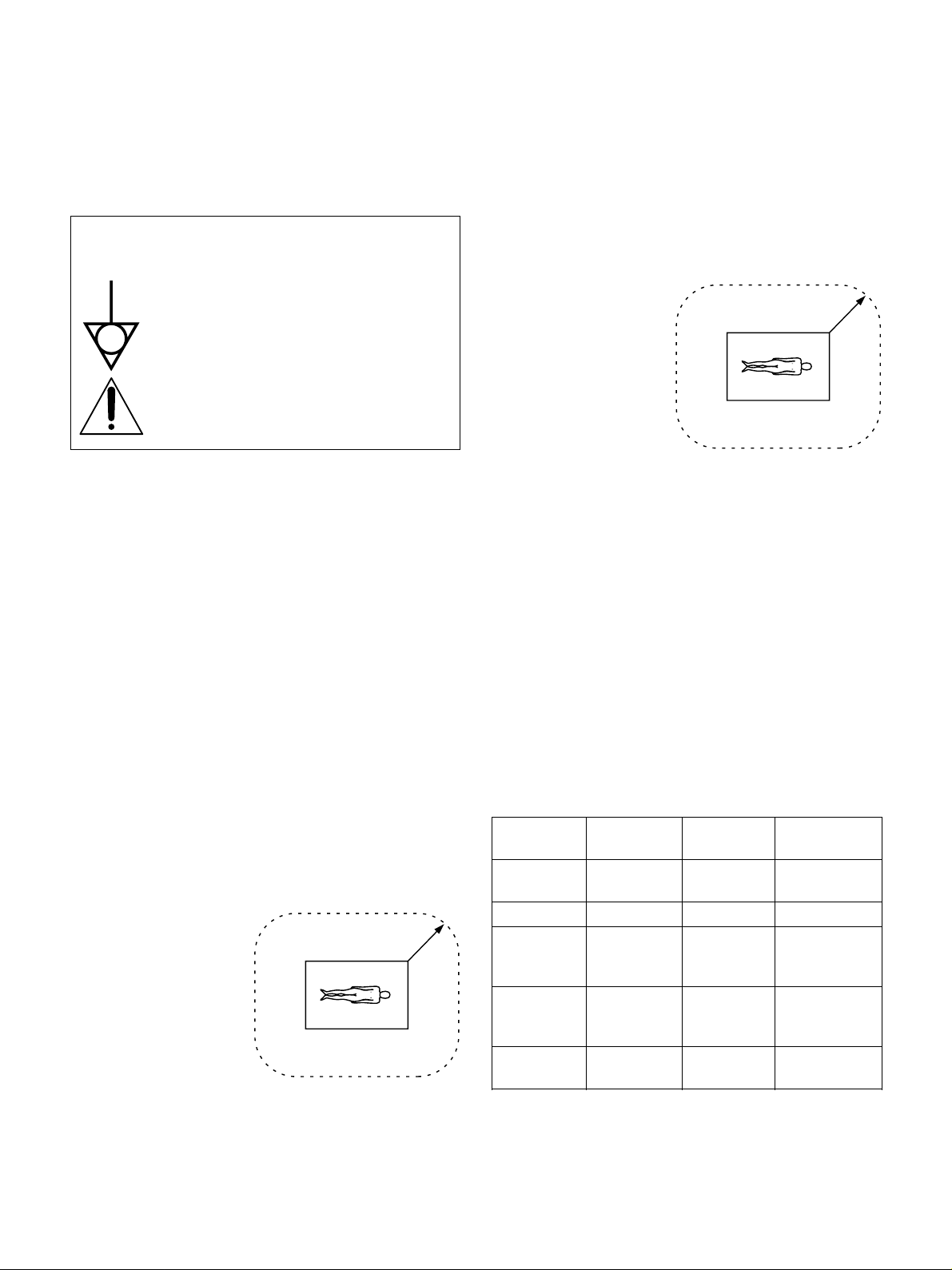
Symbol on the products
For UPA-P100MD
Important safeguards/notices for use in the
medical environments
1 All the equipments connected to this unit shall be certified
according to Standard IEC60601-1, IEC60950, IEC60065
or other IEC/ISO Standards applicable to the equipments.
2 When this unit is used together with other equipment in
the patient area*, the equipment shall be either powered
by an isolation transformer or connected via an additional
protective earth terminal to system ground unless it is
certified according to Standard IEC60601-1.
This symbol indicates the equipotential
terminal which brings the various parts of a
system to the same potential.
This symbol is intended to alert the user to the
presence of important operating and
maintenance (servicing) instructions in the
literature accompanying the appliance.
When using a LAN cable: For safety, do not connect to the
connector for peripheral device wiring that might have
excessive voltage.
For the customers in the U.S.A.
(for UPA-P100MD)
This equipment has been tested and found to comply with
the limits for a Class A digital device, pursuant to Part 15 of
the FCC Rules. These limits are designed to provide
reasonable protection against harmful interference when the
equipment is operated in a commercial environment. This
equipment generates, uses, and can radiate radio frequency
energy and, if not installed and used in accordance with the
instruction manual, may cause harmful interference to radio
communications. Operation of this equipment in a residential
area is likely to cause harmful interference in which case the
user will be required to correct the interference at his own
expense.
You are cautioned that any changes or modifications not
expressly approved in this manual could void your authority
to operate this equipment.
This device requires shielded interface cables to comply with
FCC emission limits.
Model UPA-P100MD is Non-Patient Equipment.
This unit can not be used in the vicinity of patients.
* Patient Vicinity
R1.83m
(6 feet)
* Patient Area
R1.5m
3 The leakage current could increase when connected to
other equipment.
4 This equipment generates, uses, and can radiate
frequency energy. If it is not installed and used in
accordance with the instruction manual, it may cause
interference to other equipment. If this unit causes
interference (which can be determined by unplugging the
power cord from the unit), try these measures: Relocate
the unit with respect to the susceptible equipment. Plug
this unit and the susceptible equipment into different
branch circuit. Consult your dealer. (According to
Standard EN60601-1-2 and CISPR11, Class B, Group 1)
Caution
When you dispose of the unit or accessories, you must obey
the law in the relative area or country and the regulation in
the relative hospital.
Warning on power connection for medical use
Use a proper power cord for your local power supply.
United States Canada Continental
Europe
Plug Type HOSPITAL HOSPITAL LP-34A
GRADE* GRADE*
Female end E62405 LR53182 LS-60
Cord type E159216 LL112007-1 H05VV-F
Min.Type SJT Min.Type SJT
Min.18AWG Min.18AWG
Minimum cord 10A/125V 10A/125V 10A/250V
For the customers in Canada
(for UPA-P100MD)
This unit has been certified according to Standard CSA
C22.2 NO.601.1.
set rating
Safety UL Listed CSA VDE
approval
*Note: Grounding reliability can only be achieved when the
equipment is connected to an equivalent receptacle
marked ‘Hospital Only’ or ‘Hospital Grade’.
2

The following specifications are applied only to the
UPA-P100MD:
Storage and transport temperature
–20°C to 60°C (–4°F to 140°F)
Storage and transport humidity
20 % to 80 % (no condensation allowed)
Protection against electric shock
Class I
Protection against harmful ingress of water
Ordinary
Degree of safety in the presence of flammable anesthetics
or oxygen
Not suitable for use in the presence of
flammable anesthetics or oxygen
Mode of operation
Continuous
Design and specifications are subject to change without
notice.
3

Before Using the Digital Capture Unit
About the Hard Disk
Compared to a floppy disk, a hard disk has a greater
memory capacity and needs less time to write or read
data. However, dust and vibrations affect a hard disk’s
performance. Furthermore, the same as for a floppy
disk, a hard disk should never be placed near magnetic
fields.
About the CD-R
Operation and Storage Precautions
When using the CD-R drive to write information on
discs, please pay attention to the following:
•Do not use or store the drive where it might be
subjected to vibrations or shocks.
•Do not use or store the drive in hot or humid
locations, or direct sunlight.
•When writing data on a disc, do not turn the Digital
Capture Unit off or push the Eject button of the CD-R
drive.
Hard disks contain built-in safety mechanisms to
protect data against dust and vibrations. However, to
avoid losing data, you should take the following
precautions.
•Do not use the hard disk in areas prone to vibrations
or on unstable surfaces.
•Do not move the hard disk while it is on.
•Do not turn the power off while the hard disk is
performing an operation.
•Do not use the hard disk in areas prone to sudden
temperature fluctuations (i.e. more than 10 ºC).
Note that if the hard disk is damaged, data may not be
recoverable.
Do not forget to back up the data on the hard disk.
Make sure to back up images saved on the hard disk of
the UPA-P100MD on a regular basis. Sony denies any
responsibility if data saved on the hard disk becomes
unrecoverable.
Make sure that the power cord and other
connectors are properly connected.
Improperly connected power cord or connectors
constitute a risk of fire or electric shock.
Avoiding Condensation Problems
As much as possible, avoid areas prone to sudden
temperature changes. Do not attempt to use the drive
immediately after moving it from a cold to a warm
location or raising the room temperature suddenly, as
condensation can form within the drive. If the
temperature changes suddenly while you are using the
drive, stop using it but keep the power on for at least
an hour.
Handling Discs
•Handle discs only by the edges as illustrated below.
Never touch the recording surface.
•Do not write (except with a felt-tip marker) or affix
labels to discs.
About the rear connectors
Confirm that the cable connectors you are using can be
inserted into the terminal outside of the molding. Also
note that the screw posts next to the D-sub connectors
on the rear panel of the unit are threaded in inches.
When using cables other that the one provided for use
with this unit, make sure that you use inch-threaded
screws.
Do not connect the RM-P110 to the UPA-P100MD
when it is on.
Please make sure that the UPA-P100MD is off before
connecting the RM-P110. Connecting the RM-P110 to
the UPA-P100MD when it is on could cause it to
malfunction.
•Do not store discs in dusty, dirty, or humid locations,
in direct sunlight, or near heat-generating devices.
•Avoid spilling liquid on discs.
•To protect important data, always keep discs in their
protective case.
4

Digital Captur e
Unit
User’s Guide
UPA-P100MD

Table of Contents
Before Using the Digital Capture Unit............ 4
About the Hard Disk.............................................. 4
About the rear connectors...................................... 4
About the CD-R..................................................... 4
Overview
Operation
Grabbing Images............................................ 19
Viewing Images .............................................. 20
Printing Images .............................................. 22
Saving Images to CD-R Discs ....................... 22
Accessing Images on a CD-R Disc............... 23
Finishing Examinations................................. 24
Managing UPA-P100MD Hard Disk Space ... 24
Digital Capture Unit Overview......................... 7
Features ............................................................ 8
Built-in CD-R ........................................................ 8
Remote Control Unit ............................................. 8
Linux Operating System........................................ 8
Networking Capabilities........................................ 8
Direct Printout Capabilities ................................... 8
Presentation of the Digital Capture
Unit
Front Panel ....................................................... 9
Rear Panel....................................................... 10
Remote Control .............................................. 11
Setup
Preliminary Connections............................... 12
Saving Images to Your Computer ....................... 24
Saving Images to CD-R discs.............................. 25
Specifications and Troubleshooting
General Specifications .................................. 26
UPA-P100MD Audible Signals ...................... 27
Pin Assignments ............................................ 28
Parallel Port Pin Assignments ............................. 28
Remote Control Port Pin Assignments................ 29
Troubleshooting............................................. 30
Troubleshooting................................................... 30
Preliminary Settings ...................................... 13
Connecting the Digital Capture Unit to a
Network ........................................................... 14
Configuring the UPA-P100MD....................... 15
The Configuration Screen ............................. 16
Microsoft and Windows are registered trademarks of Microsoft Corporation.
Other company names and product names mentioned in this guide are also trademarks and registered trademarks.
6
Overview
Digital Capture Unit Overview
The Digital Capture Unit is used to record analog
images from video devices in JPEG and TIFF format.
As need arises, it is also possible to save the recorded
images on CD with the built-in CD-R drive or print the
images with a digital color printer (UP-D50, UPD70XR). Furthermore, if the unit is connected to a
network, users can preview the images on the unit’s
hard disk using an Internet browser.
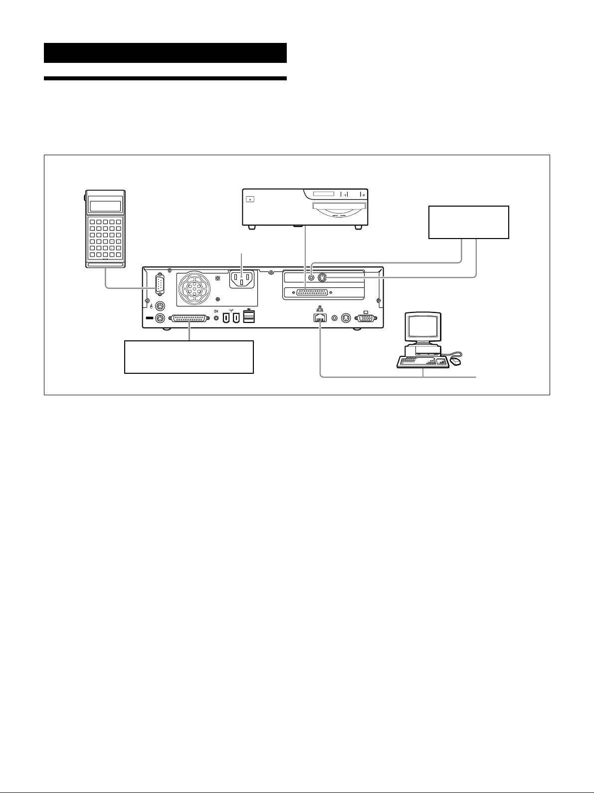
RM-P110 Remote
Control Unit
DBAC
ESCF4F2F1 F3
IHFEG
BSF8F6F5 F7
NMKJL
213
SRPOQ
546
XWUTV
879
ZY
ENTSPABCabc
0
RM-P110
AC Power Inlet
UP-D50 or UP-D70XR
Digital Color Printers
External Control Device
(not provided by Sony)
The illustration above presents the connections of the
UPA-P100MD. For explanations about the UPAP100MD connectors and rear panel, see “Rear Panel”
on page 10. For more about the RM-P110 Remote
Control Unit, see “Remote Control” on page 11 and
consult the Remote Control Unit User’s Guide on page
31. For explanations about how to connect the UPAP100MD to a network, see “Connecting the Digital
Capture Unit to a Network” on page 14.
TV OUT
AV S-VIDEO
Video Device
PC
Network
(if applicable)
7

Features
Built-in CD-R
The built in CD-R drive of the Digital Capture Unit
allows you to save images to CD-R discs. Using the
Digital Capture Unit’s configuration screen, you can
choose to write images to CD-R discs using either
single-session or multi-session recording.
Remote Control Unit
The remote control allows one-touch control of the
unit. With its standard 80-character display, its 8
function keys, and uppercase and lowercase typing
capabilities, the remote control unit is versatile and
easy to use.
Linux Operating System
The flexibility of the Linux operating system does not
require long shutdown and start-up procedures. This
means that you can turn the unit on or off as you like,
except when writing information on a CD-R disc or the
hard disk.
Networking Capabilities
Although the Digital Capture Unit is connected to a
single computer during setup, it can also be configured
for use through a local area network (LAN). This is
highly useful when it is necessary for several users to
share view images on the unit’s hard disk. However,
you can only control image capture and recording with
the remote control unit or a custom-made control unit,
not through the network.
Direct Printout Capabilities
Connecting a digital color printer such as the UP-D50
or UP-D70XR to the Digital Capture Unit allows
images to be printed directly from the Digital Capture
Unit.
8
Presentation of the Digital Capture Unit
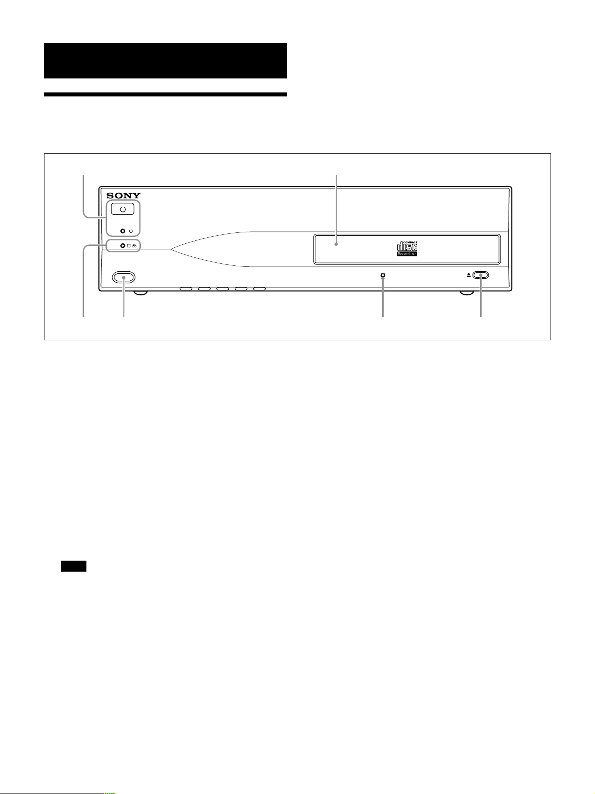
Front Panel
This section describes the unit’s front panel.
12
DIGITAL CAPTURE UNIT UPA-P100MD
6
1 Power switch and indicator
This button turns the unit on or off. The green
indicator lights up when the unit is on.
2 CD-R drive
The CD-R drive is used to write the images
captured on the unit’s hard disk to CD-R discs. The
images on the CD-R disc created with the unit's
CD-R drive can be accessed from any CD-ROM
drive.
3 CD-R drive eject button
This button is used to open or close the CD-R
drive. When writing to a CD-R disc, this button
should not be used.
Note
Because the CD-R tray opens automatically after
writing on a disc, do not place any obstruction in
front of the CD-R tray.
345
4 CD-R drive Busy indicator
This indicator blinks when the CD-R drive is busy
writing information on a CD-R disc.
5 IrDA infrared receptor
Currently not supported.
6 HDD, LAN access indicator
This indicator blinks amber when the hard disk of
the unit is being accessed. It blinks green when the
LAN is accessed.
9
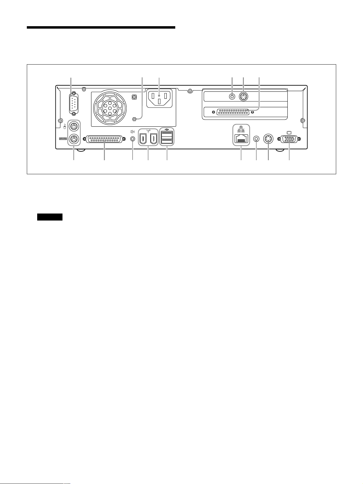
Rear Panel
This section describes the unit’s rear panel.
1
23 456
1 Remote control port (D-sub, 9-pin)
When using the RM-P110 Remote Control Unit
(sold separately), connect it to this port.
Warning
This connector outputs 5 V; therefore do not
connect it to any device other than the RM-P110
Remote Control Unit or other control device
designed for use with the UPA-P100MD. If you
connect a device other than the remote control to
this connector, there is a risk of damage to the
device.
TV OUT
AV S-VIDEO
7890qaqsqdqfqg
6 SCSI port (half-pitch, 50-pin)
This port connects to a digital color printer.
Compatible printers are the UP-D50 and UPD70XR.
Their SCSI default settings are:
•Terminator: on
•ID: 001
Refer to the appropriate printer user’s guide for
details.
7 RGB output (D-sub, 15-pin)
This port is used for servicing purposes only.
2 Equipotential terminal
When connected, this terminal ensures that all the
system components are at the same electrical
potential.
3 AC power inlet
Connect to a power outlet using the provided
power cord.
4 Video input (RCA PIN jack)
Input analog video signals. Connect to the optical
device's video output.
5 S-video input (mini DIN 4-pin)
Input analog s-video signals. Connect to the optical
device's s-video output.
8 S-video output (Mini DIN 4-pin)
Currently not supported.
9 Video output (RCA PIN jack)
Currently not supported.
0 Network port (10Base-T/100Base-TX, RJ-45)
This port is used to connect to a network with a
LAN cable.
qa USB port (2, series A, 4-pin)
Currently not supported.
qs IEEE 1394 port (2)
Currently not supported.
qd Speaker output
Currently not supported.
10
qf Parallel port (D-sub, 25-pin)
This port is used to connect to a custom-made
external control unit to control the device. Refer to
the pin assignments in the “Specifications and
Troubleshooting” chapter of this guide.
qg PS2 port (2, mini DIN, 6-pin)
These ports are used for servicing purposes only.
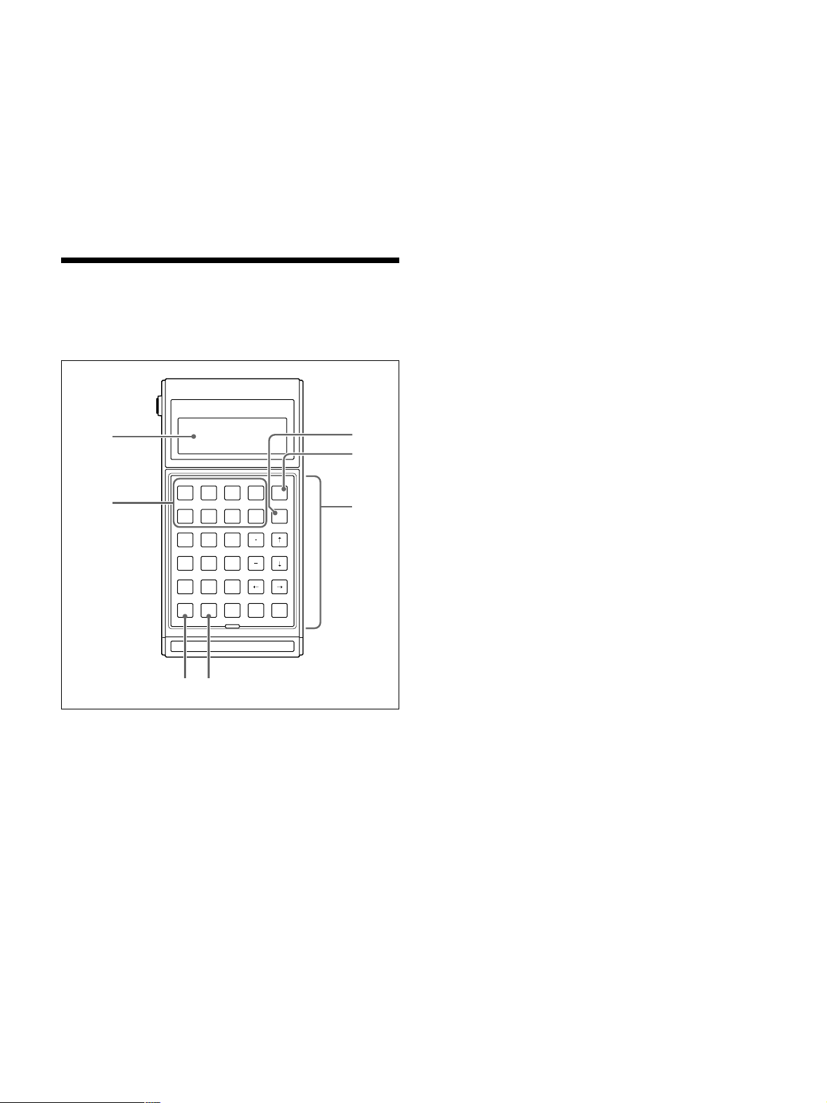
Remote Control
This section describes the RM-P110 Remote Control
Unit (sold separately).
1
4
3
DBAC
7
213
546
879
0
RM-P110
ESCF4F2F1 F3
IHFEG
BSF8F6F5 F7
NMKJL
SRPOQ
XWUTV
ZY
ENTSPABCabc
2
56
5 [ABC] key
Allows you to enter uppercase text. The operation
of this key can be changed. Refer to the RM-P110
Remote Control Unit User’s Guide for details.
6 [abc] key
Allows you to enter lowercase text. The operation
of this key can be changed. Refer to the RM-P110
Remote Control Unit User’s Guide for details.
7 Function keys
You can assign strings of up to 16 characters to
each of the 8 function keys. This allows you to
assign doctor names, patient names, or procedure
names to the function keys. Refer to the RM-P110
Remote Control Unit User’s Guide for details.
1 Display
The LCD display of the remote control displays
messages and input commands. It can display 4
lines of 20 alphanumerical characters.
2 Keyboard
The keyboard is composed of 26 alphanumerical
keys, 8 function keys, a backspace key, an escape
key, a space key, and an enter key.
3 Escape key
The [ESC] key allows you to cancel an operation,
such as typing the name of a doctor.
4 Backspace key
The [BS] key allows you to go back one space to
correct mistakes.
11
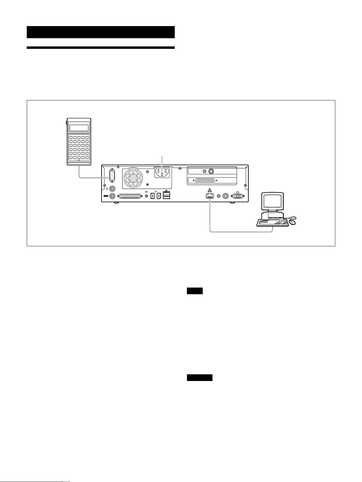
Setup
Preliminary Connections
Before using the UPA-P100MD (locally or through a
network), you need to make certain connections. To
make these connections, use the following procedure.
RM-P110 Remote
Control Unit
DBAC
ESCF4F2F1 F3
IHFEG
BSF8F6F5 F7
NMKJL
213
SRPOQ
546
XWUTV
879
0
RM-P110
ZY
ENTSPABCabc
AC Power Inlet
1 Locate the UPA-P100MD’s power cord.
2 On the rear panel of the device, locate the AC inlet.
3 Connect the female end of the power cord to the
AC inlet.
4 Connect the RM-P110 Remote Control Unit
connector to the remote control port on the rear
panel. When using a foot switch or other such
external control device, connect the foot switch to
the parallel port on the rear panel of the UPAP100MD.
5 On the rear panel of the UPA-P100MD, locate the
network port. Connect a LAN cross cable to this
port.
TV OUT
AV S-VIDEO
PC
6 Connect the other end of the LAN cross cable to
the network port of your computer. You are now
ready to make preliminary settings.
Note
•Before connecting the unit, make sure that you are
using the appropriate type of cross cable. If you are
not sure of what type of cable to use, ask your system
administrator.
•If your computer is connected to a network, to be able
to make the preliminary settings of the UPAP100MD, it is necessary to isolate your computer
from the network so that the connection between the
UPA-P100MD and your computer is local.
Warning
The Remote control port outputs 5 V; therefore do not
connect it to the RM-P110 Remote Control Unit when
the UPA-P100MD is on.
12
 Loading...