

Page 1

REMOTE CONTROL UNIT
RM-B750
電気製品は、安全のための注意事項を守らないと、火災
や人身事故になることがあります。
このオペレーションマニュアルには、事故を防ぐための重要な注意事項と製
品の取り扱いかたを示してあります。このオペレーションマニュアルをよく
お読みのうえ、製品を安全にお使いください。お読みになったあとは、いつ
でも見られるところに必ず保管してください。
OPERATION MANUAL
[Japanese/English]
1st Edition
Page 2
安全のために
ソニー製品は安全に十分に配慮して設計されています。しかし、電気製品は
まちがった使い方をすると、火災や感電などにより死亡や大けがなど人身事
故につながることがあり、危険です。
事故を防ぐために次のことを必ずお守りください。
安全のための注意事項を守る
2(J)〜3(J)ページの注意事項をよくお読みください。
定期点検を実施する
長期間安全に使用していただくために、定期点検を実施することをおすすめ
します。点検の内容や費用については、ソニーのサービス担当者または営業
担当者にご相談ください。
故障したら使用を中止する
ソニーのサービス担当者または営業担当者にご連絡ください。
万一、異常が起きたら
警告表示の意味
このオペレーションマニュアル
および製品では、次のような表
示をしています。表示の内容を
よく理解してから本文をお読み
ください。
この表示の注意事項を守らない
と、火災や感電などにより死亡
や大けがなど人身事故につなが
ることがあります。
この表示の注意事項を守らない
と、感電やその他の事故により
けがをしたり周辺の物品に損害
を与えたりすることがあります。
異常な音、に
おい、煙が出
たら
炎が出たら
1 電源を切る。
,
2 ソニーのサービス担当者または営業担当者に修
理を依頼する。
すぐに接続コードを抜き、消火する。
,
注意を促す記号
行為を禁止する記号
Page 3

目次
警告 ....................................................................................................................
注意 ....................................................................................................................
概要 .........................................................................................................................
特長 .................................................................................................................................. 4(J)
各部の名称と働き ....................................................................................................
操作パネル ...................................................................................................................... 5(J)
コネクターパネル .......................................................................................................... 9(J)
メニューの構成と基本操作 ....................................................................................
基本操作手順 ................................................................................................................ 10(J)
メニュー画面の基本構成 ............................................................................................ 11(J)
メニュー項目 ................................................................................................................ 15(J)
初期設定 ................................................................................................................
RM-B750の動作環境の設定 ........................................................................................ 22(J)
時計を合わせる ............................................................................................................ 22(J)
ブザーを設定する ........................................................................................................ 23(J)
LEDの明るさを設定する ............................................................................................ 24(J)
液晶ディスプレイの明るさを設定する .................................................................... 24(J)
メモリースティック ...............................................................................................
メモリースティックの取り付け ................................................................................ 25(J)
メモリースティックについて .................................................................................... 25(J)
主な仕様 ................................................................................................................
2(J)
3(J)
4(J)
5(J)
10(J)
22(J)
25(J)
27(J)
日
本
語
1 (J)
Page 4
下記の注意を守らないと、
火災や感電により死亡や大けがにつながることがあります。
外装を外さない、改造しない
外装を外したり、改造したりすると、感電の原因となります。
内部の調整や設定および点検を行う必要がある場合は、必ずサービストレー
ニングを受けた技術者にご依頼ください。
内部に水や異物を入れない
水や異物が入ると火災や感電の原因となります。
万一、水や異物が入ったときは、接続コードを抜いて、ソニーのサービス担
当者または営業担当者にご相談ください。
油煙、湯気、湿気、ほこりの多い場所では設置•使用しない
上記のような場所で設置・使用すると、火災や感電の原因となります。
2 (J)
Page 5
下記の注意を守らないと、
けがをしたり周辺の物品に損害を与えることがあります。
CAMERA
続しない
このオペレーションマニュアルに記載している以外の機器を接続すると、
火災や感電の原因となることがあります。
リモートコントロールケーブルを傷つけない
リモートコントロールケーブルを傷つけると、火災の原因となることがあ
ります。
端子や
MONITOR
端子には指定以外の機器を接
3 (J)
Page 6

概要
RM-B750は、ソニーのBVP/HDCシリーズ放送局用CCDカラービ
デオカメラの調整機能を、手元でリモートコン トロールするためのリ
モートコントロールユニットです。
付属の専用ケーブルでカメラに直接接続することにより、カメ ラか
ら最大50m離して使用することができます。
特長
RM-B750の主な特長は次のとおりです。
カメラの基本的オペレーションに対応
カメ ラの基 本的オペレーションに必要な機能を、手元でコントロール
することが できます。
タッチパネルと
LCDに表示される機能をタッチパネルで選択することにより、各機
能の設定を変更することができます。
カメ ラのビューファ イ ンダーに表示されるカメ ラ側のメニュ ー を、本
機のLCDに表示させて設定することも可能です。
制御機能
VTR
カメ ラに接続されたVTRやカムコーダーのテープ走行を、本機から
制御する こ と ができ ます。
3.5型LCD
により各種機能に対応
S-EVS
スーパーEVS(EnhancedVerticalDefinitionSystem)機能対応
のカメラの垂直解像度を、本機から調整できます。
機能対応
メモリースティックスロット搭載
シー ン ファイル、リファレンスファイルなど各 種データをメモリース
ティックに保存し、必要なときに読み出して再現させるこ とができ
ます。
他のコントロールパネルとのパラレルコントロー
ルが可能
カメ ラコントロールユニットを介してカ メラに接続 した場合は、マス
ターセッ トアップユニットMSU-700A/750やRCP-700シリーズなど、
他のリモートコン トロー ラー との併用も可能になり ます。
HDCU-950
本機の裏蓋を取り外すことによって、HDカメラコントロールユニッ
トHDCU-950への取り付けが可能になります。HDCU-950一体型
の操作パネルとして、カメラやHDCUの機能をコントロールするこ
とができます。
◆HDCU-950への取り付けについては、HDCU-950のインストレーシ ョンマ
ニュ アルを参照 してください。
に取り付け可能
自動調整機能のコントロール
カメ ラのホワイトバランス、ブラックバランスの自動調整を、本機か
ら実行することができます。
カメラの
CCDカメラのECS(ExtendedClearScan)や電子シャッター機能
のON/OFFに加え、ECS周波数やシャッタースピードの切り 換えが
可能です。
シャッター機能をコントロール
ECS/
4 (J)
Page 7
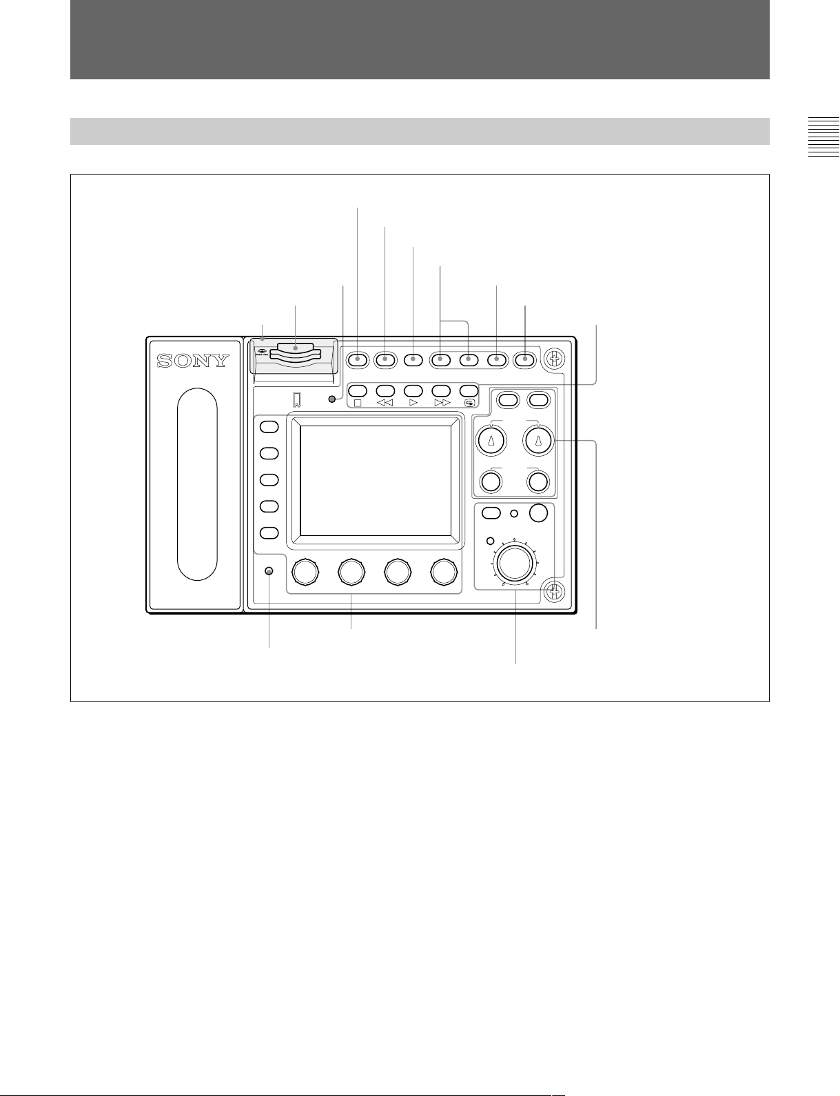
各部の名称と働き
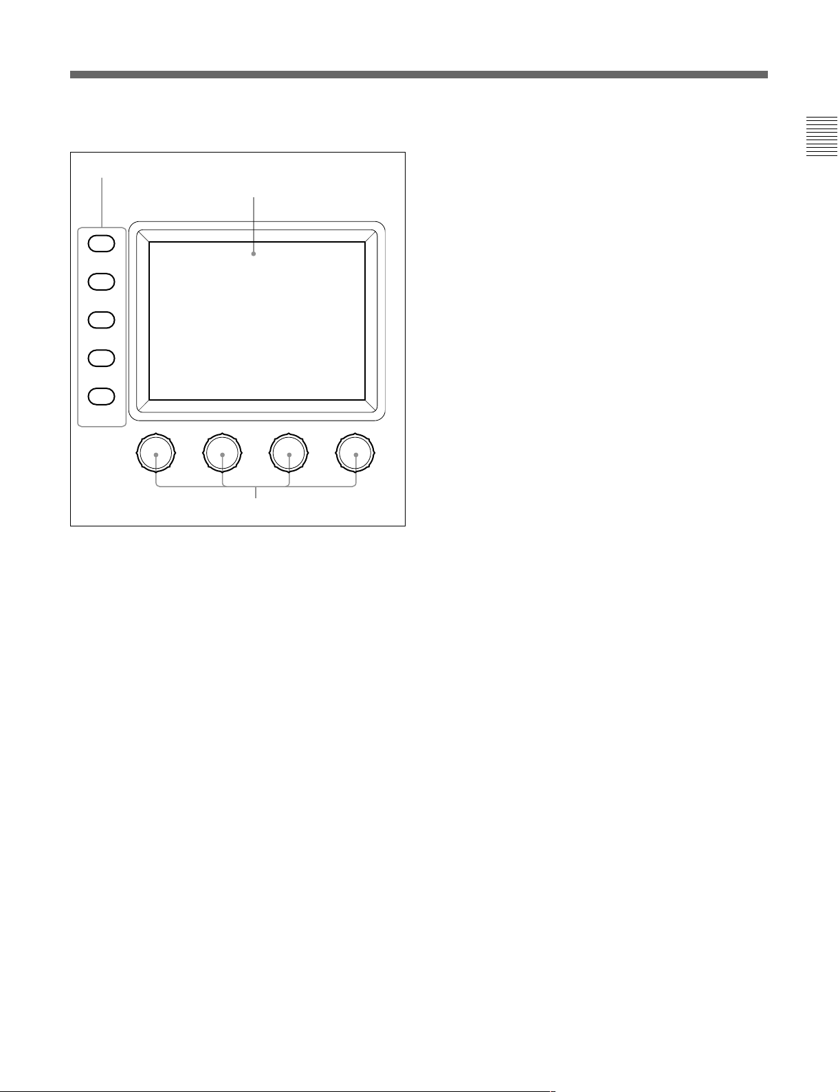
操作パネル
2
MEMORY STICK
1
メモリースティックスロット
ゴムキャップ
MONITOR
FUNCTION
VF DISP
MAINTENANCE
VF MENU
SCENE
CANCEL
PAI NT
ENTER
ALARM
MENU SELECT
MEMORY
STICK
ランプ
3
PANEL ACTIVE
4
STANDARD
5
スペアボタン
テスト信号出力選択ボタン
6
PAN EL
STANDARD TEST BARS CLOSE
ACTIVE
REMOTE CONTROL UNIT RM-B750
ボタン
ボタン
IRIS
AUTO
IRIS
EXT
7
CLOSE
START/STOP
AWB
WHITE
BLACK
IRIS/MB
ACTIVE
ボタン
8
VTR START/STOP
VTR
ABB
MASTER
BLACK
9
VTR
ボタン
再生制御ボタン
qa
メニュー操作部
0
ALARM
インジケーター
1 メモリースティックスロット
カメ ラやカメラ コントロールユニ ットのリ ファレンスフ ァイル、シーン
ファイル などを 保 存 する
メモリースティックをス ロットに 挿 入しま
す。
2
MEMORY STICK
(メモリースティックアクセス)ラン
プ
メモリースティックの状態を表示しま す 。
消灯:メモリースティックが挿入されていま せん。
緑点灯:
メモリースティックが挿入され ています。この状態のと
メモリースティックを安全に抜くことが できます。
きは
赤点灯:データの読み出し/書き込み中です。この状態でメモ
リースティック
を抜き差しすると、 データは保証されません。
全データが消えてしまうこともあります。
◆メモリースティ ックについては、25(J)ページをご覧ください。
qd
ホワイトバランス/ブラック
バランス調整部
qs
アイリス/マスターブラック調整部
3
PANEL ACTIVE
(パネルアクティブ)ボタン
本機に接続したカ メラシステムに対す る制御モードを切り換えます。
工場出荷時は、ボタンを押すごとに、FULLモード、PARTモード、
LOCKモードが切り換わるよう に設 定されています。
モード:本機のすべてのコントロール機能が有効です(パ
FULL
ネルアク テ ィブ状態)。このボタ ンと 、 アイリス / マ スターブラッ
ク調整部のIRIS/MBACTIVEインジケーターの両方が点 灯し
ます。
モード:アイリス/ マスターブラック調 整 部のコン トロール機
PART
能のみが有効です(アイリス/ マスターブラックアクティブ状
態)。このボタ ンは消灯し、IRIS/MB ACTIVEインジケーター
のみが点灯します。
モード:本機のすべてのコントロール機能が無効に なりま
LOCK
す(ロック状態)。このボタンとIRIS/MBACTIVEインジケー
ターの両方が消灯します。
5 (J)
Page 8

各部の名称と働き
メンテナンスメニューのR Mコンフ ィ ギュレ ー ション(RMConfig)メ
ニューでFULLとLOCKモードのみを切り換えるよ うに変更 するこ
と もでき ます
なお、RMコンフィギュ レー ションメニューは、どのモードに設 定され
ていても操作することができます。
4
STANDARD
押す とビデオカメラの各種設定が標準状態になり、ボタ ンが数秒間
点灯します。
ボタンが点灯している間にもう1度押すと、点灯する前の状態に戻
ります 。
5 スペアボタン
将来の機能拡張用です。現在は機能しません。
6 テスト信号出力選択ボタン
押して点灯させると、 カメ ラのテスト信号発生器が作動し、対応す
る信号が出力されます。
TEST
(20(J)ページ)。
BARS
ご注意
BARSボタンが点灯している場合は、BARSボタンの機能が優先し
ます。 TESTを選択するときは、BARSボタンを押して消灯させてく
ださい。
(20(J)ページ)。
(標準)ボタン
(テスト):ビデオ回路チェック用の テスト信号。
出力されるテスト信号の種類は、メンテナ ンスメニューの RM
コンフィギュレーショ ンメニューで選 択 することができます
(カラーバー):カ ラ ー バー信号
9
VTRの再生動作を制御します。
s(停止)ボタン
再生、早送り 、巻き戻し を停止します。
j(巻き戻し)ボタン
押して点灯させると、巻き戻しが始ま ります。
G(再生)ボタン
押して点灯させると、再生が始ま ります 。
J(早送り)ボタン
押して点灯させると、早送りが始ま ります。
7
押して点灯させると、記録レビューを実行します。
●
●
0
システム に異常が発生し、 カ メラヘ ッドやカメラコントロールユニッ
トで自己診断機能が動作すると、赤く点滅・点灯します。
再生制御ボタン
VTR
(記録レビュー)ボタン
ご注意
VTRSTART/STOPボタン点灯中は、VTR再生制御ボタンは機
能しません。 VTRSTART/STOPボタンを押して記録モードを解
除してから、希望のボタンを押してください。
カメラとVTRの組み合わせによっては、VTR制御が一部できな
い場合もあります。詳しく は、ソニーの 担当者にお問い合わせくだ
さい。
ALARM
(アラーム)インジケーター
7
CLOSE
押して点灯させると、絞りがクローズします。 もう1度押すとボタン
は消灯し、クローズが解除されます。
8
VTR START/STOP
押して点灯させると、 記録が始まります 。 もう1度押して消灯させる
と記録が停止します。
このボタンは、メンテナンスメニューのR Mコンフ ィ ギュレ ー ションメ
ニューでCALL(コ ール)ボタンとして機能するように設定すること
ができます
にコール信号が送出され、カメラ側のCALLボタンが点灯します。
また、カメ ラのタ リーランプとカメラコン トロールユニットのレッ ドタ リー
ランプは、それぞれ点灯していた場合は消灯し、消灯 し ていた場
合は点灯します。
カメラ側でCALLボタンが押されると、本機のこのボタンが点灯し、
ブザーが鳴りま す。
(アイリスクローズ)ボタン
(記録スタート/ストップ)ボタン
(20(J)ページ)。その場合、ボタンを押すとビデオカメラ
6 (J)
Page 9
qa メニュー操作部
A
メニュー選択/カメラメニュー操作ボタン
RM
MONITOR
FUNCTION
VF DISP
MAINTENANCE
VF MENU
SCENE
CANCEL
PAINT
ENTER
B
LCD/
タッチパネル
SCENE
(シーンファイル)
/CANCEL
(キャンセル):
MONITORボタン消灯時は、このボタンを押して点灯させる
と、本機のシーンファイル操作メニューが液晶ディスプレイに表
示されます。
MONITORボタン点灯時は、液晶ディスプレイで選択 したカ
メラメニュー項目の設定をキャンセルします。
PAINT
(ペイント)
/ENTER
(確定):MONITORボタン消灯時
は、このボタ ンを押して点灯させると 、本機のペイントメニ ュー
が液晶ディスプレイ に表示 されます。
MONITORボタン点灯時は、液晶ディスプレイで選択 したカ
メラメニュー項目の設定を確定します。
すべてのボタンを消灯さ せると、ステータス表示 (11(J)ページ)に
なります。
◆それぞれのメニ ュ ーの項目については、「メニュー項目」(15(J)ページ)
をご覧ください。 カメラメニューについ て詳しく は、カ メラのオペ レーショ
ンマニュアルまたはシス テ ムマニュアルを参照してください。
MENU SELECT
C
調整つまみ
A
メニュー選択/カメラメニュー操作ボタン
RM
MONITOR
(モニター):消灯時は、他のボタンで本機メニュー
を選択できます(RMメニューモード:白い文字で表示されて
いる機能が有効)。
押して点灯させると、接続したカメラのビデオ信号
(SDTV信号の場合のみ)が液晶ディスプレイ に表 示されま
す。またカメラのメニューを本機から操作可能になります(各
ボタンの青い文字で表示されている機能および左端の調
整つまみが有効)。
FUNCTION
(ファンクション)
/VF DISP
(ビューファイン
ダー表示):MONITORボタン消灯時は、このボタ ンを押し
て点灯 させると、本 機 のファンクションメニューが液晶ディスプ
レイ に表 示されます。
MONITORボタン点灯時は、このボタンを押して点灯させる
と、 カメラのキャラク ター表示が ONになり ます。
MAINTENANCE
(メンテナンス)
/VF MENU
(ビューファイ
ンダーメニュー):MONITORボタン消灯時は、このボタン
を押して点灯させると 、本機のメ ンテナンスメニューが液晶
ディ スプレイ に表示されます。
MONITORボタン点灯時は、このボタンを押して点灯させる
と、カメラメニューモードになり、カメラのメインメ
ニューが液晶ディスプレイに表示されます。
B
通常はステータス
(液晶ディスプレイ)/タッチパネル
LCD
(11(J)ページ参照)を表示します。
MONITORボタンを押して点灯させると、接続したカメラのビデオ
信号を表示します (ただしSDTV信号のみで、HDTV信号の場合
は表示されません)。
RMメニューモード ま たはカメラ メ ニューモードでは、それぞれ選択
したメニューが表示され、各種の設定が可能になります。
調整つまみ(ロータリーエンコーダー)
C
RMメニューモードでは、タッチパネルで選択した項目を調整しま
す。カ メラ メ ニュ ーモードでは、左端のつまみでメニューの選択や
設定を行います。
7 (J)
Page 10
各部の名称と働き
qs アイリス/マスターブラック調整部
D
IRIS/MB ACTIVE
インジケーター
A
AUTO IRIS
ボタン
B
EXT
ケーター
C
IRIS
A
AUTO IRIS
インジ
つまみ
IRIS/MB
AUTO
IRIS
EXT
IRIS
ACTIVE
MASTER
BLACK
(自動絞り)ボタン
E
MASTER BLACK
つまみ
押して点灯させると、レンズの絞りが入力光に応じて自動的に調整
されます。 も う1 度押すと消灯し、絞りの手動調 整が可能になりま
す。
B
(レンズエクステンダー)インジケーター
EXT
カメ ラ側でレンズエクステンダーを使用している とき点灯します。
C
(アイリス調整)つまみ
IRIS
AUTOIRISボタン消灯時は、レンズの絞りを手動調整します。
AUTOIRISボタン点灯時は、自動調整の基準値を微調整(±2F)
します。
工場出荷時は、絶対値モードで調整するように設定されています
が、メンテナンスメニューの RM コンフ ィギュレーションメニュー
で相対値モードでの調整に変更することもできます
D
IRIS/MB ACTIVE
(アイリス/マスターブラックアク
(20(J)ページ)。
ティブ)インジケーター
PANELACTIVEボタンで制御モードがFULLまたはPARTモード
に設定されていると点灯します。このボタンが点灯していると き は、
本機で絞りとマスタ ーブラッ クの調整が行えます。
E
MASTER BLACK
(マスターブラック調整)つまみ
マスターブラックの手動調整を行います。
工場出荷時は、相対値モードで調整するように設定されています
が、メンテナンスメニューの RM コンフ ィギュレーションメニュー
で絶対値モードでの調整に変更することもできます
(20(J)ページ)。
9 ホワイトバランス/ブラックバランス調整部
A
AWB
WHITE
BLACK
(ホワイトバランス自動調整)ボタン
AWB
ABB
A
B
C
D
ボタン
AWB
ボタン
ABB
WHITE
BLACK
つまみ
つまみ
押すと、ホワイトバランスが自動調整されます。
調整中はボタンが点灯し、調整が完了すると消灯します。
自動調整実行中にもう1度このボタン を押すと 、自動調整が中止さ
れ、ボタンが点滅します。もう1 度ボタ ンを押すと点滅が止まり ま
す。
B
(ブラックバランス自動調整)ボタン
ABB
押すと、 ブラ ッ クバラ ンス、 ブラ ッ クセ ットが自動調整されます。
調整中はボタンが点灯し、調整が完了すると消灯します。
自動調整実行中にもう1 度このボタ ンを押すと、 自動調整が中止さ
れ、ボタ ンが点滅します。もう 1度ボタン を押すと点滅が止まります。
ご注意
ブラ ックバランス手動調整つ まみが絶対値モードに設定されている
ときは 、 ABBボタンによるブラッ クバラ ンスの自動調整はできません。
C
WHITE
(ホワイトバランス手動調整)つまみ
R/Bのホワイトバランスを調 整します。
工場出荷時は、相対値モードで調整するように設定されています
が、メンテナンスメニューの RM コンフ ィギュレーションメニュー
で絶対値モードでの調整に変更することもできます
D
BLACK
(ブラックバランス手動調整)つまみ
(20(J)ページ)。
R/Bのブラックバランスを調整します。
工場出荷時は、相対値モードで調整するように設定されています
が、メンテナンスメニューの RM コンフ ィギュレーションメニュー
で絶対値モードでの調整に変更することもできます
(20(J)ページ)。
8 (J)
Page 11
コネクターパネル
2 リモートコントロールケーブルをCAMERA端子に、BNCケーブ
ルをMONITOR端子に差し込む。
1
CAMERA
端子
2
MONITOR
端子
カバー固定ネジ
1
CAMERA
(カメラ)端子(8ピン)
付属のリモートコン トロールケーブルでカメラに接続します。
2
MONITOR
(モニター)端子(
BNC
型)
カメ ラからの信 号をモニターするためのカラーモニターを接続しま
す。
接続のしかた
C
A
M
A
R
A
M
O
N
ITO
R
ケーブル(別売り)
BNC
リモートコントロールケーブル(付属)
3 カバ ーを 元通りに 閉め、ネジを 締める。
CAMARA
MONITOR
1 底面のカバー固定ネ ジ を緩めて、カバー を開け る。
C
A
M
A
R
A
M
O
N
IT
O
R
9 (J)
Page 12
メニューの構成と基本操作
RM-B750では、メニュー操作により、システム機器の調整など
様々 な機能に対応します。
基本操作手順
本機のメニューを設定する
ときは消灯
MONITOR
FUNCTION
VF DISP
MAINTENANCE
VF MENU
SCENE
CANCEL
PAINT
ENTER
MENU SELECT
2
2 操作する項目を選択する。
メニュー画面の項目ボタンを押し、設定・調整画面または操
作エリアを表示させます。
メニューが複数ページある場合は
ペイントメニュー やファンクションメ ニューのよう にメ ニュ ーが複
数ページある場合は、vまたは Vを押して 、必要に応じてメ
ニューのページを切り換えます。
◆次ページ「初期画面(ペイントメニュー)」参照。
サブメニューがある場合は
ボタンを押して設定・調整画面を切り換えます。
◆12(J)ページ「サブメニュー」参照。
3 項目を設定・調整する。
• 設定・調整項目(パラメーター) に対応するつまみを回して
(またはボタンを押して )、希望の値に調整(希望の設定を選
択)します。
◆12(J)ページ「設定・調整画面」参照。
• メッセージが表示された場合は、メッセー ジに従って操作 し、
[OK]を押します。
13
メニュー選択ボタンがすべて消 灯していると きは、ディ スプレイはス
テータス表示(次ページ参照)になっ ています。
1 本機のメニューを表 示させると きは、メニュー選択ボタンのい
ずれかを押して点灯させる。
メニュー操作モードになり 、押したボ タンに対応する メ ニュ ーが
ディ スプレイ に表示されます。
FUNCTION
◆画面構成については14(J)ページ、メニュー項目については21(J)
ページをご覧く ださい。
MAINTENANCE
◆メニュー項目については19(J)ページ、設定については「初期設
定」(22(J)ページ)をご覧く ださい。
SCENE
◆画面構成と操作については13(J)ページをご覧ください。
PAINT
◆画面構成については12(J)ページ、メニュー項目については15(J)
ページをご覧く ださい。
:ファンクションメ ニュー
:メンテナンスメニュー
:シーンフ ァイ ル操作メニュー
:ペイントメニュー
設定・調整が終わったら
• 引き続き同じメニューの別の項目を設定・調整するときは、その
項目のボタンを押します。
• 引き続き別のメニューの設定・調整を行うときは、対応するメ
ニュー選択ボタンを押してメ ニ ューを切り 換 えます。
• メニュー操作 モー ドを解除 するときは、 点灯しているメニ ュー 選択
ボタ ンを押します。
• ファンクションメニューは、 現在設定・調整しているメニューを解
除しないで選択することができます。
下記のいずれかの方法でファンクションメニューを解除 すると、
ファンクションメニューに切り 換える前に表示されていたメニュー
画面に戻ります。
- FUNCTIONボタンを押して消灯させる。
- 点灯 してい る(直前に表示さ れていたメニュ ーの)メニュー選
択ボタンを押す。
10 (J)
Page 13
メニュー画面の基本構成
ステータス表示
メニュー操作部でメニュー(FUNCTION、MAINTENANCE、
SCENE、PAINT)を選択 し ないと(メ ニ ュー選択ボタンがすべて
消灯)、ディ スプレイ は下図のようなステータス表示になります。
ステータス表示では、各項目は状態表示
のみで、設定はメニューや操作パネルの
つまみで行います。
これらの項目は、ファンクション
メニューで設定できます。
シーンファイル操作メニューで
選択したファイル番号が表示さ
れます。
Shutter
Gamma
0.45
White Mem : A
Scene File : 1
M. Gain
60 0dB
ND
1
ND
A
White
00
Black
0
0
M. Blk
0
Iris
CL
これらの項目は、操作パネルの
WHITE、BLACK、MASTER
、
BLACK
できます。
の各つまみで調整
IRIS
初期画面(ペイントメニュー)
メニュー操作部のPAINTボタンを押すと、ペイントメニューが表示
されます。ペイ ントメニューは8ページ構成です。
例:ページ2の初期画面
設定値をクリアすることができます。
この画面で調整可能な項目の名称が
表示されます。
調整したい項目の部分を押すと、押
した部分の色が変わり、パネルの下
半分が調整画面になります(次ぺ−
ジ参照)。
Clear
White Black Flare Gamma
ページ番号/総ページ数
2 / 8
押すと、メニューのページ(1〜8)が
順次切り換わります。
11 (J)
Page 14
メニューの構成と基本操作
設定・調整画面(ペイントメニュー)
ペイントメニューの初期画面で項目を選択すると、画面の下半分が
選択した項目の設定・調整画面になります。
例:ページ2の初期画面で
押すと、モニター出力設定画面(次
ページ参照)が上半分に表示されま
す。
を選択したとき
White
Clear
White Black Flare Gamma
WF/PIX
Select
R
0
G
0
サブメニュー
初期画面で選択した項目内で調整パラメーター等が多い場合 、サ
ブメニューが表示さ れます。
White
2 / 8
ATW
B
0
初期画面で選択した項目名が表示されま
す。
を押してからこの部分を押すと、
Clear
選択した項目の全調整値が標準状態に戻
ります。
調整に関連する
場合は、この列に表示されます。
選択した項目の調整パラメーターおよ
び調整値が表示されます。
それぞれに対応する位置の調整つまみ
で調整することができます。
を押して調整値を押すと、調整
Clear
値が標準状態に戻ります。
ON/OFF
機能がある
例:ページ3の初期画面で
Skin Detail
サブメニュー
を選択したとき
Clear
V Mod
Saw
WF/PIX
Select
123
Level
WF/PIX
Select
123
Level
2 / 8
Skin
Detail
Phase
0
Phase
0
Sat
Skin Detail
0
Skin Detail
0
Black
Gamma
Skin
Width
サブメニューで調整パラメーターを切り換えます。
Width
DTL 1
Sat
0
0
0
Skin
DTL 2
Sat
0
12 (J)
Page 15
モニター出力設定画面(拡張メニュー)
ペイントメニューの設定・調整画面で[WF/PIX Select]を押して点灯
させると、画面上半分にモニター出力設定画面が表示されます。
WF/PIX Monitor Select
R G B RGB SEQ ENC
表示を戻したいときは、もう1度
この項目を押してください。
WF/PIX
Select
シーンファイル操作メニュー画面
:それぞれR信号、G信号、
R/G/B
信号を選択します。
B
RGB:R
SEQ:WF
ENC
信号、G信号、B信号を組み
合わせて選択できます。
出力のみ有効で、R、G、
つの信号の波形をシーケン
Bの3
シャルモードでモニターすること
ができます。
:エンコードされた信号が出力
されます。
メニュー操作部のSCENEボタンを押すと、シーンファイル操作メ
ニュー画面にな ります。
シーンファイルの呼び出し:
呼び出したいシーンファイルの番号を選択
して押すと、登録されているファイルが呼
び出されます。
このとき呼び出されているシーンファイル
番号は色が変わります。
同じシーンファイル番号を押すと呼び出さ
れる前の状態に戻ります。
Scene File Recall
12345
Store
シーンファイルの登録:
を押して点灯させてから、希
Store
望するシーンファイル番号を選択し
ます。ファイル登録が終了すると
の色が元に戻ります。
Store
13 (J)
Page 16
メニューの構成と基本操作
ファンクションメニュー画面
メニュー操作部のFUNCTIONボタンを押すと、ファンクションメ
ニュー画面にな ります。
Operation
Filter Ctrl
この画面でフィルターを選択でき
る状態になります。
選択時
を押して色を変えると
v
Vを押して希望するフィルターを選択します。
/
フィルター、CCフィルターの枚数はカメラに依存します。
ND
Opera-
tion
Filter
Ctrl
SW WHITE
ND GammaCC
1 A 0.45
Shutter ECS
Master
Gain
60 30.00 0dB
それぞれ対応する位置の調整つまみで
調整できます。
v
Vを押してガンマ値を選択します。
/
±
ステップで変更できます。
0.05
v
Vを押してマスターゲインを選択し
/
ます。
vを押すたびに値が大きくなり、
Vを押すたびに小さくなります。
SW
選択時
Opera-
tion
S-Skin
Knee
Sat Mono
Black
Gamma
5600K
それぞれ対応する機能を
Off
の機能が
択(点灯)時に機能がONになります。
SW WHITE
Low Key
Sat
Auto
Knee
の表示があるボタンは選択(点灯)時にそ
OFF
ATW PsF
Knee
Aperture
Skin
Detail
になり、それ以外のボタンは選
Knee
Sat
Detail
Gate
ON/OFF
します。
ページ番号/総ページ数
1 / 2
押すと、メニューのページが切り換わ
ります。
14 (J)
Page 17
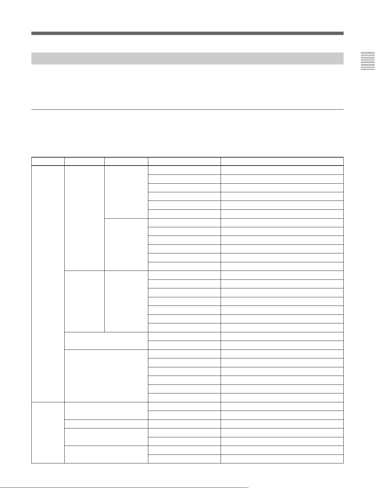
メニュー項目
操作/調整項目欄で●が付いている項目は調整つまみに割り当て
られる項目、それ以外の項目は、メニュー画面上で操作する項目
です。
ペイントメニュー
ペイントメ ニューは 8 ページで構成されています。
各ページのv/Vを押すこと によって、ページ1〜8を順 次切り換え
ることが できます。
ページ メニュー サブメニュー 操作/調整項目 機能
SD
a)
●Level HDディテールレベル調整
●Limiter HDディテールリミッター調 整
●Crispening HDディテールク リスプ ニン グ調整
●LevelDep HDレベルディペンド調整
DetailOff HDディテールON/OFF
SDDTLOff SDディテールON/OFF
a)
●Level SDディテールレベル調整
●Limiter SDディテールリミッター調 整
●Crispening SDディテールク リスプニング調整
●LevelDep SDレベルディペンド調整
DetailOff HDディテールON/OFF
SDDTLOff SDディテールON/OFF
●Phase スキンディテール色相調整
●Width スキンディテール色相幅調整
●Saturation スキンディテールサチュ レーション調整
DTLGate# スキンディテールゲートON/OFF(チャンネル別)
AutoHue# スキンディテールオートヒュー(チャンネル別)
SkinDTL# スキンディテールON/OFF(チャンネル別)
FlareOff フレアON/OFF
●BlkGamma マスターブラックガンマ調整
●KneePoint マスターニーポイント調整
●KneeSlope マスターニースロープ調整
GammaOff ガンマON/OFF
KneeOff ニーON/OFF
ATW オートトレース ホワイトバラ ンス調整
FlareOff フレアON/OFF
GammaOff ガンマON/OFF
Paint1/8 Detail1 HD
SkinDetail 1/2/3(項目共通) ●Level スキンディテールレベル調整
Flare ●R/G/B フレアバランス調整
Gamma/Knee ●Gamma マスターガンマ調整
Paint2/8 White ●R/G/B ホワイトバラ ンス調整
Black ●R/G/B/Master ブラックバランス調整
Flare ●R/G/B フレアバランス調整
Gamma ●R/G/B/Master ガンマ調整
a)HDカメラ接続時のみ、HD/SDのサブメニューが表示されます。
15 (J)
Page 18
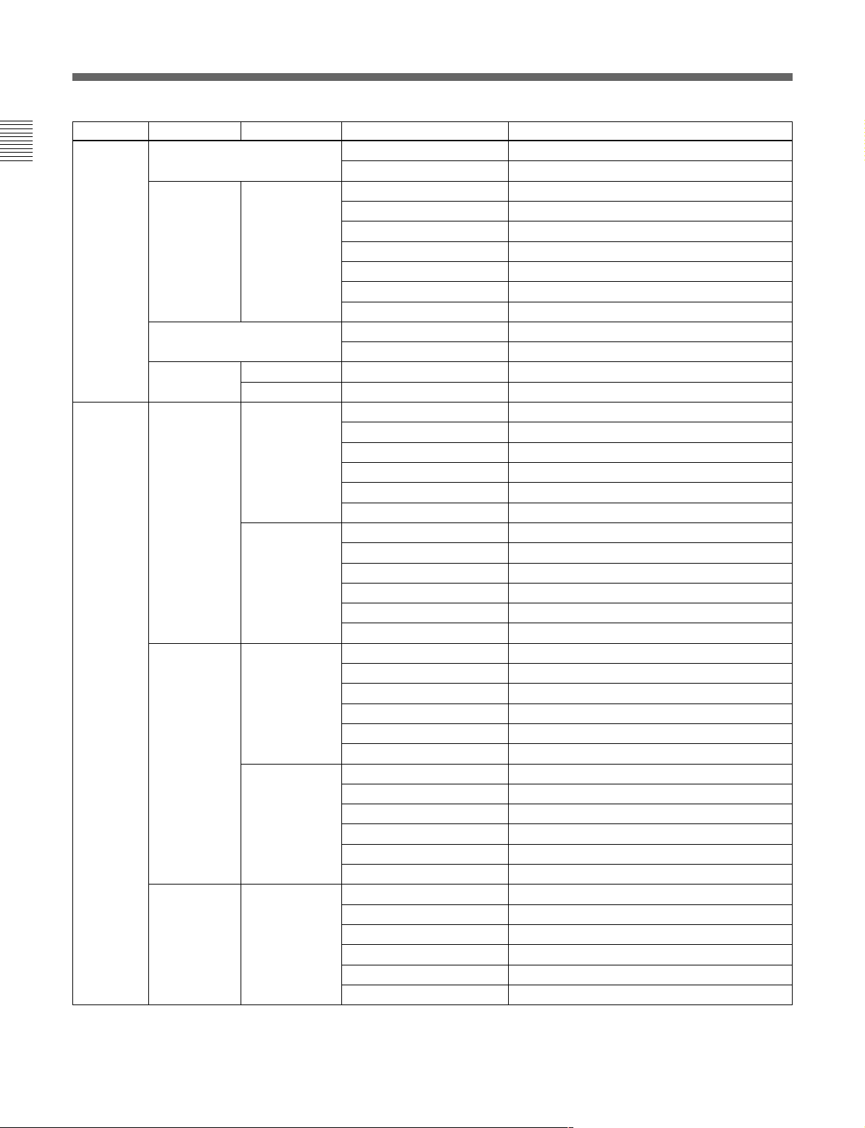
メニューの構成と基本操作
ページ メニュー サブメニュー 操作/調整項目 機能
Paint3/8 VModSaw ●R/G/B/Master Vモジュレーション調整
VModSawOff VモジュレーションON/OFF
SkinDetail 1/2/3(項目共通) ●Level スキンディテールレベル調整
●Phase スキンディテール色相調整
●Width スキンディテール色相幅調整
●Saturation スキンディテールサチュ レーション調整
DTLGate# スキンディテールゲートON/OFF(チャンネル別)
AutoHue# スキンディテールオートヒュー(チャンネル別)
SkinDTL# スキンディテールON/OFF(チャンネル別)
Saturation ●Saturation サチュレーション調整
Saturation サチュレーションON/OFF
BlackGamma RGB ●R/G/B/Master ブラックガンマ調整
Y ● Yブラックガンマ調整
SD
SD
a)
●Level HDディテールレベル調整
●Limiter HDディテールリミッター 調 整
●Crispening HDディテールク リスプ ニング 調 整
●LevelDep HDレベルディペンド調整
DetailOff HDディテールON/OFF
SDDTLOff SDディテールON/OFF
a)
●Level SDディテールレベル調整
●Limiter SDディテールリミッター 調 整
●Crispening SDディテールク リスプニング調整
●LevelDep SDレベルディペンド調整
DetailOff HDディテールON/OFF
SDDTLOff SDディテールON/OFF
a)
●H/VRatio HDディテールH/Vレシオ調整
●Frequency HDディテールブースト周波数調整
●MixRatio HDディテールミックスレシオ調整
●Comb HDディテールコム調整
DetailOff HDディテールON/OFF
SDDTLOff SDディテールON/OFF
a)
●H/VRatio SDディテールH/Vレシオ調整
●Frequency SDディテールブースト周波数調整
●MixRatio SDディテール ミックスレシオ 調 整
●Comb SDディテールコム調整
DetailOff HDディテールON/OFF
SDDTLOff SDディテールON/OFF
a)
●W.Limiter HDディテールホワ イトリミッター調 整
●B.Limiter HDディテールブラックリミッター 調 整
●Fine HDファインディテールレベル調整
●KneeApert HDニーアパーチャー調整
FineDetail HDファインディテールON/OFF
KneeAperture HDニーアパーチャーON/OFF
Paint4/8 Detail1 HD
Detail2 HD
Detail3 HD
a)HDカメラ接続時のみ、HD/SDのサブメニューが表示されます。
16 (J)
Page 19

ぺ−ジ メニュー サブメニュー 操作/調整項目 機能
Paint4/8 Detail3 SD
(続き) (続き)
a)
●W.Limiter SDディテールホワ イトリミッター 調 整
●B.Limiter SDディテールブ ラックリミッター 調整
●Coring SDクロスカラーレデュースコアリング調整
●Level SDクロスカラーレデュースレベル調整
CrsColReduce SDクロスカラーレデュースON/OFF
CrossColorSuppression ●CCSLevel クロスカラーサプレッションレベル調整
●N.Level ノッチレベル調整
●Frequency ノッチ周波数調整
CCS クロスカラーサプレッションON/OFF
Paint5/8 KneePoint ● R/G/B/Master ニーポイント調 整
KneeOff ニーON/OFF
KneeSlope ●R/G/B/Master ニースロープ調整
KneeOff ニーON/OFF
Matrix Matrix1 ●R-G/G-B/B-R マトリックス定数設定
UserMatrix ユーザーマトリックスON/OFF
PresetMatrix プリセットマトリックスON/OFF
MatrixOff 全マトリックスON/OFF
Matrix2 ●R-B/G-R/B-G マトリックス定数設定
UserMatrix ユーザーマトリックスON/OFF
PresetMatrix プリセットマトリックスON/OFF
MatrixOff 全マトリックスON/OFF
MultiMatrix ●Phase マルチマトリックス領 域選択
●Hue マルチマトリックス色 相 設定
●Sat マルチマトリックス彩 度 設定
MultiMatrix マルチマトリックスON/OFF
MatrixOff 全マトリックスON/OFF
AllClear 全マルチマトリックス設 定をクリア
Paint6/8 Gamma/Knee ●Gamma マスターガンマ調整
●BlkGamma マスターブラックガンマ調整
●KneePoint マスターニーポイント調整
●KneeSlope マスターニースロープ調整
GammaOff ガンマON/OFF
KneeOff ニーON/OFF
KneeSaturation ●KneePoint マスターニーポイント調 整
●KneeSlope マスターニースロープ調整
●Level ニーサチュレーションレベル調整
KneeOff ニーON/OFF
KneeSat ニーサチュレーションON/OFF
LowKeySaturation ●Level LowKeyサチュレーションレベル調整
LowKeySat LowKeyサチュレーションON/OFF
WhiteClip ●R/G/B/Master ホワイトクリップ調整
WhiteClipOff ホワイトクリップON/OFF
a)HDカメラ接続時のみ、HD/SDのサブメニューが表示されます。
17 (J)
Page 20

メニューの構成と基本操作
ぺ−ジ メニュー サブメニュー 操作/調整項目 機能
Paint7/8 GammaTable ●Standard ガンマテーブル設定
●User ユーザーガンマテーブル設定
Standard 標準ガンマテーブル選択
User ユーザーガンマテーブル選択
GammaOff ガンマON/OFF
AutoKnee ●PointLimit オートニー時のニー ポイントの下限値設定
●AutoSlope オートニー時のニースロ ープ調整
Adaptive アダプティブハイライトコントロールON/OFF
KneeOff ニーON/OFF
AutoIris ●Phase スキントーンオ ートア イ リス色相調整
●Width スキントーン オートアイリス色相幅調整
NormalMode オートアイリスノーマ ル モード選択
SkinMode オートアイリス ス キ ンモード選択
IrisAutoHue オートヒュー調整
AutoIrisGate スキントーン オートアイリス ゲートON/OFF
ECS/S-EVS ●Shutter シャッタースピード選択
●ECS ECS周波数選択
●S-EVS スーパーEVS調整
Shutter シャッターON/OFF
ECS ECSON/OFF
S-EVS スーパーEVSON/OFF
Paint8/8 SDGamma ●SDGamma SDガンマ調整
●BlkGamma ブラックガンマ調整
●MGamma マスターガンマ調整
GammaOff ガンマON/OFF
CrossColorReduce ●Comb クロスカラーレデュースコム調整
●Coring クロスカラーレデュースコアリング調整
●Level クロスカラーレデュースレベル調整
CrsColReduce クロスカラーレデュースON/OFF
18 (J)
Page 21

メンテナンスメニュー
次メニュー2次メニュー サブメニュー 操作/調整項目 機能
1
Adjusting BlackShading R/G/B ●HSaw/HPara/VSaw/VPara ブラックシェーディング調整
AutoBShading オートブラックシェーディング調整
WhiteShading R/G/B ●HSaw/HPara/VSaw/VPara ホワイトシェー ディング調整
AutoWShading オートホワイ トシェーディング調整
Phase HPhase ● HStep H位相の調整
●HCoarse
●HFine
SCPhase ●SC SC位相の調整
●BF ブラックバースト信号位相の調整
AutoIris ●(パターン) オートアイリスパターン の選択
●Level オートアイリスレベル調整
●APLRatio オートアイリスAPLレシオ調整
●IrisGain オートア イ リスゲ イン調整
AutoSetup AutoWhite ホワイトバラ ンス自動調整
AutoBlack ブラックバランス自動調整
AutoWhiteShading ホワイトシェー ディング自動調整
AutoBlackShading ブラックシェーディング自動調整
AutoLevel オートレベル自動調整
AutoHue SkinDetail1 スキンディテールオートヒュー調整
SkinDetail2
SkinDetail3
SkinAutoIris スキントーン オートアイ リス 調 整
Camera PresetMatrix SMPTE-240M プリセットマ トリックスの 設定
Config
RMConfig RMAdjusting BuzzerVolume ● Call コールブザーの音量設定
LEDBrightness ●Switch 各LEDの明るさの設定
ITU-709
SMPTEWide
NTSC
EBU
ITU-601
●Touch タッチパネルの反応音量の設定
●Switch 照光スイッチの確認音量の設定
●Master 全体の音量設定
CallBuzzer コールブザーのON/OFF
TouchClick タッチパネル音のON/OFF
SWClick スイッチ音のON/OFF
AllOff 全ブザー音のON/OFF
●Other
●Master 全体の明るさの設定
19 (J)
Page 22

メニューの構成と基本操作
次メニュー2次メニュー サブメニュー 操作/調整項目 機能
1
RMConfig Date/Time Date ● Year 本機内蔵の時計の日付合わせ
(続き) ●Month
●Day
Set
Cancel
Time ● Hour 本機内蔵の時計の時刻合わせ
●Minute
●Second
Set
Cancel
SWSetting ActiveMode ActiveMode PANELACTIVEボタンの動作モードの切り 換え
Setting Mode2:FULL/LOCK
Mode3:FULL/PART/LOCK
TEST TESTMode TESTボタンを押すと出力される信号(Saw、3STEP、
10STEP)の選択
VTRSTART/STOP SWMode VTRSTART/STOPボタンの機能(VTR機能、
CALL機能)の選択
CableComp Length ビデオ信号を利用する際のケーブル補正値の調整
VRSetting WhiteR/B ABS/REL ホワイト手動調整モード(絶対値/相対値)の切り換え
Scale 相対値モード時の可変範囲(1/1、1/2、1/4)
BlackR/B ABS/REL ブラック手動調整モード(絶対値/相対値)の切り換え
Scale 相対値モード時の可変範囲(1/1、1/2、1/4)
MasterBlack ABS/REL マスターブラック調整モード(絶対値/相対値)の
切り換え
Scale 相対値モード時の可変範囲(1/1、1/2、1/4)
IRIS ABS/REL アイリス調 整 モード(絶対値/相対値)の切り換え
●Min アイリスの最小コントロール値の設定
●Max アイリスの最大コントロール値の設定
Information 本機のソフトウェアバージョ ン表示
Security 本機のセキュリティの設定
LCD LCDBrightness ●Bright 本機の液晶ディスプレイ の明るさ 設定
File ReferenceFileStore リフ ァレンスファイル登録
ReferenceFileTransfer CAM–>MS リファレンスファイル 転 送( カメラからメモリースティック)
MS–>CAM リファレンスファイル 転 送(メモ リースティックからカメラ)
SceneFileTransfer CAM–>MS シーンファイル転送(カメラからメモリースティック)
MS–>CAM シーンファイル転送(メモリ ースティックからカメラ)
OHBFileStore OHBファイル登録
SuperMotion FieldRate [x1,x3] SuperMotionカメラ使用時のフィール ド レ ートの設定
FrameInterpolation [OFF,A,B,C] 3倍動作時に標準出力画像を作るパタ ーンの設定
FlickerReduction [OFF,Normal,Strong] 3倍動作時のフリッカー除去の設定
MemoryStick MemoryStick Format メモリースティックのフォ ーマット
20 (J)
Page 23

ファンクションメニュー
メニュー サブメニュー 操作/調整項目 機能
Operation FilterCtrl フィルターリモート/ローカルモー ドの選択
ND(1/2/3/4/5) NDフィルターの選択
CC(A/B/C/D/E) CCフィルターの選択
Gamma ステップガンマの選択
MasterGain マスターゲインの選択
Shutter シャッターモードのON/OFF
ECS ECSモードのON/OFF
●Shutter シャッタースピードの選択
●ECS ECS周波数の選択
SW page1 5600K 5600Kの電気色温度補正機能のON/OFF
AutoKnee オートニー機能のON/OFF。ONでは、ハイライト が入ると自動的にニーが働く。
SkinDetail 肌色部分(顔など)のディテールを抑制するスキントーン ディテール機能のON/OFF
DetailGate スキントーン ディテールゲート機能のON/OFF。
ONでは、スキントーン ディテールの調整範囲がモニター上に白く表示される。
BlackGamma ブラックガンマ機能のON/OFF
KneeAperture ニーアパーチャー機能のON/OFF
KneeSat ニーサチュレーション機能のON/OFF
Sat サチュレーション機能のON/OFF
Mono 輝度信号に単一色相のクロマ信号をミックスするためのモノカラー機能のON/OFF。
ONでは、クロマレベルが輝度信号で変調される。
S-SkinKnee スーパースキンニー機能のON/OFF
LowKeySat 暗部でのクロマレベル補正機能のON/OFF
ATW オートトレーシ ングホワイト機能のON/OFF
PsF CCDのプログレッシブ読み出し動作機能のON/OFF
page2 KneeOff ニー補償機能のON/OFF(点灯時OFF)
GammaOff ガンマ機能のON/OFF(点灯時OFF)
DetailOff 輪郭補正を行うディテール機能のON/OFF(点灯時OFF)
MatrixOff 忠実な色再現を行うためのリニアマトリックス機能のON/OFF(点灯時OFF)
WhiteClipOff ハイライト信号のリミッター機能のON/OFF(点灯時OFF)
LevelDepOff 暗部でのディテールを抑制する レベルディ ペ ンド機能のON/OFF(点灯時OFF)
ChromaOff クロマ機能のON/OFF(点灯時OFF)
SDDetailOff HDTVカメラ接続時にSD出力のディテール機能のON/OFF(点灯時OFF)
SDMatrixOff HDTVカメラ接続時にSD出力のリニアマトリックス機能のON/OFF(点灯時OFF)
WHITE Preset プリセット状態のホワイトバラ ンスの選択
MemoryA メモリーA状態のホワイト バラ ンスの選択
MemoryB メモリーB状態のホワイトバラ ンスの選択
21 (J)
Page 24

初期設定
RM-B750
の動作環境の設定
設定画面を表示させるときは、[LCD]を押す。
LCD
メンテナンスメニューのR Mコンフィ ギュレー ションメニュ ーやLCD
設定画面では、RM-B750に内蔵されている時計の時刻合わせや、
警告ブザー音の音量、インジケーターやディ スプレイの明るさを調 整
する こ ともでき ます。
コンフィギュレーションメニュー
RM
/LCD
設定
画面を表示させるには
次の手順で操作します。
本機のメニューを設定する
ときは消灯
1
MAINTENANCE
MONITOR
FUNCTION
VF DISP
VF MENU
SCENE
CANCEL
Adjusting File
RM
Config
Maintenance Menu
Auto
LCD
Camera
Config
Setup
Super
Motion
Memory
Stick
2
LCD設定画面(24(J)ページ)に切り換わります。
時計を合わせる
RM-B750には、メモリースティックにリ ファレンスファイルやシーン
ファイ ル を保存した日時を記録する ための時計が内蔵されていま
す。
時計合わせは、次の手順で行います。
1 RMコンフィギュ レー ション メ ニュ ーの[Date/Time]を押す。
時計合わせメニューに切り換わり、現在の設定が表示されま
す。
Date Time Set Menu
Date Time
2001/11/17
(Sat)
: 12 :
31
22
Exit
PAINT
ENTER
MENU SELECT
1 メニュー操作部のMAINTENANCEボタンを押して点灯させ
る。
メンテナンスメニューが表示されます。
2
コンフィギュレーションメニューを表示させるとき
RM
[RM Config]を押す。
は、
RMコンフィギュレーションメニューに切り換わり ます。
RM
Adjusting
Cable
Comp
RM Config Menu
SW
SettingVRSetting
Exit
Infor-
mation
Date
Time
Secu-
rity
2 日付を合わせる。
1) [Date]を押 して点灯させる。
Date Time Setting
2001/11/17
(Sat)
22 : 12 : 31
Date Time
Year
Month
2001
8
Set Cancel
Day
8
2) 左3つの調整つまみでそれぞれ年(Year)、月(Month)、
日(Day)を合わせる 。
[Set]を押す。
3)
設定した日付が有効になります。
[Set]を押す前に[Cancel]を押すと元の日付に戻ります。
Exit
22 (J)
Page 25

3 時刻を合わせる。
[Time]を押 して点灯させる。
1)
2 [Buzzer Volume]を押 して点灯させる。
ディ スプレイの下半分が、ブザー設定画面になります。
Date Time Setting
2001/11/17
(Sat)
22 : 12 : 31
Date Time
Hour
Minute32Second
17
2) 左の 3つの 調整つまみ でそれぞ れ 時(Hour)、分
(Minute)、秒(Second)を合わせる。
3)ラジオなどの時報に合わせて
設定した時刻が有効になります。
Set Cancel
25
Exit
[Set]を押す。
[Set]を押す前に[Cancel]を押すと元の時刻に戻ります。
日時の設定が終わったら
[Exit]を押して メニュ ーを抜けます。
ブザーを設定する
RM-B750では、コール信号を受信したときや、パネルを操作する
と ブザー音が聞こ えます。
必要に応じて、ON/OFFしたり、音量を調整してください。
設定は、次の手順で行います。
Clear
Buzzer
Volume
Call
Buzzer
Call
50
LED
Bright
Buzzer
Volume
Touch
Click
Touch50Switch Master
SW
Click
50 50
All
Off
Exit
3 対応する調整つまみで、ブザーの音量を調整する(標準設定
値はすべて50)。
:コール信号受信時のブザーの音量
Call
:メニュー画面 (タ ッ チパネル)に表示された操作ボ
Touch
タンを押 した ときのブザーの音量
Switch
右端のつまみ(
ブザーを個別に
対応するボタンを押します。点灯時がONになります。
[Call Buzzer]:コール信号受信時のブザー
[Touch Click]:メニュー画面(タ ッチパネル)に表示された操作
ボタ ンを押したと きのブザー
[SW Click]:操作パネル上のボタンを押したときのブザー
:操作パネル上のボタン を押したときの ブザーの音
量
Master
ON/OFF
)で、全体の音量を調整できます。
するには
1 RMコンフィギュレーションメ ニュ ーの[RM Adjusting]を押す。
RM設定メニューに切り換わります。
Clear
Buzzer
Volume
LED
Bright
Exit
ブザー音をすべて
OFF
にするには
[All Off]を押して点灯 させます。
設定が終わったら
[Exit]を押して メニュ ーを抜けます。
23 (J)
Page 26

メニューの構成と基本操作
の明るさを設定する
LED
RM-B750では、操作ボタンやインジケーターのLEDの明るさを調
整できます。
1 RMコンフィギュ レ ーションメニューの[RM Adjusting]を押 して、
RM設定メニューに切り換える。
2 RM設定メニューの[LED Bright]を押して点灯させる。
ディ スプレ イの下半分が、LED明るさ設定画面になります。
Clear
Buzzer
Volume
Switch
50
LED
Bright
Other
LED
Brightness
50
Exit
Master
50
液晶ディスプレイの明るさを設定する
LCD設定画面で、メニュー操作部の液晶ディスプレイの明るさ を調
整できます。
1 メンテナンスメニューの[LCD]を押して、LCD設定画面に切り
換える 。
Clear
LCD Brightness
Bright
Exit
50
2 左端の調整つまみで、Bright(明るさ)を調整する(標準設定
値は50)。
3 対応する調整つまみで、LEDの明るさを調整する(標準設定
値はすべて50)。
Switch
Other
右端のつまみ(
設定が終わったら
[Exit]を押して メニュ ーを抜けます。
:操作ボタン内蔵のLEDの明るさ
:インジケー ター/ラ ンプのLED の明る さ
Master
)で全体の明るさを調整できます。
設定が終わったら
[Exit]を押して メニュ ーを抜けます。
24 (J)
Page 27

MONITOR
FUNCTION
VF DISP
N
A
NC
E
PAN
EL
ACT
IVE
MEMOR
Y
STICK
STANDARD
メモリースティック
メモリースティックの取り付け
別売りの メモリースティックを使用すると 、ファイル情 報を 保 存し、
他のリモートコン トロールユニットで も同じファイル情報 を共有するこ
とができます。
メモリースティックを取り付けるには
ゴムキ ャッ プを はずし、ラ ベル面を手前に して 、端子を奥に向けて
メモリースティック装着部に差し込みます。カチッと 音がして、ア
クセスランプが赤く点灯するまで差し込んでください。
ラベル面
メモリースティック
ゴムキャップ
メモリースティックについて
メモリースティックとは?
メモリースティックは、小さ くて 軽く、しかもフロッピーディスクより
容量が大きい新世代のIC記録メディアです。
対応機器間でデータを やりとりする のにお使いいただける だけでな
く、着脱可能な外部記録メディアの1つとしてデータの保存にもお
使いいただけま す。
メモリースティックの種類
メモリースティックには、著作権保護技術(マジックゲ ート)を搭
載したマジック ゲ ートメモリースティ ックと、搭載 していない一般
のメモリースティックの2種類があります。
本機ではマジックゲートメモリースティ ックと一般のメモリー
スティックのどちらもご使用いただけます。ただし、本機はマ
ジックゲー ト規格に対応 していないため 、本機で記録したデータは
マジッ クゲートによる著作権の保護の対象にはなりません。
メモリースティック
アクセスランプ
ご注意
アクセス ランプが赤く 点灯している間はメモリースティックの抜き
差しはしないでく ださい。
メモリースティックを外すには
装着されている
メモリースティック を押します。先端が少し出てき
ますので、引き抜きます。
アクセスランプについて
アクセス ラ ンプがメモリースティックの状態を表示しま す 。
消灯:メモリースティックが挿入されていま せん。
緑点灯:
赤点灯:データの読み出し/書き込み中です。この状態でメモ
メモリースティックが挿入されています。この状態のと
メモリースティックを安全に抜くことが できます。
きは
リースティック
を抜き差しすると、 データは保証されません。
全データが消えてしまうこともあります。
マジックゲートとは?
マジ ッ クゲートは、暗号化技術を使って著作権を保護する技術で
す。
メモリースティックの構造
端子
誤消去防止つまみ
ラベル貼り付け部
誤消去防止つまみを「LOCK」にすると記録、消去などができなく
なります。
大切なデータはバックア ップを取っておく ことをお 奨めします。
25 (J)
Page 28

メモリースティック
メモリースティックの取り扱いについてのご注意
• 以下の場合、データが破壊されることがあります。
―読み込み中、書き込み中に
本機の電源を切った場合
―静電気や電気的ノイズの影響を受ける場所で使用した場合
大切なデータはバックア ップを取っておく ことをお 奨めします。
• 端子部に触れた り、金属を接触させたりしないでください。
• ラ ベルの貼 り 付け部には、専用ラベル以外は貼 らないでください。
• ラベルを貼るときは所定のラ ベル貼り付け部に 貼ってください。は
みださないようにご注意ください。
• 強い衝撃を与えたり、曲げたり、落したりしないでください。
• 分解したり、改造したりしないでください。
• 水にぬらさないでください。
• 以下のような場所でのご使用や保管は避けてください。
―高温になった車の中や炎天下などの気温の高い場所
―直射日光のあたる場所
―湿気の多い場所や腐食性のある場所
• 持ち運びや保管の際は付属の収納ケースに入れてください。
• RM-B750で使用できる容量の
では使用できない場合があります。
メモリースティックを使っ てカメラとデータ を交換する際は、カメ
ラとRM-B750双方で使用可能な容量の
使用ください。
メモリースティックを抜いた り、
メモリースティックは、カ メラ 側
メモリースティック をご
• MemoryStick(メモリースティック)および は、
ソニー株式会社の商標です。
• MagicGateMemoryStick(マジックゲートメモリースティック)
および
は、ソニー株式会社の商標です。
26 (J)
Page 29

主な仕様
一般
電源 DC10.5〜30V
消費電力 最大4W
最大ケーブル長 50m
動作温度 5℃〜40℃
最大外形寸法 197
質量 0.7kg
入出力
CAMERA 8ピンマルチコネクター(1)
MONITOR BNC(1)
付属品
×124×62mm
(幅/高さ/奥行き)
専用リモートコン トロールケーブル(10m)(1)
オペ レーションマニュアル(1)
別売りアクセサリー
メンテナンスマニュアル
メモリ ースティック
本機の仕様および外観は、改良のため予告なく変更することがあ
りますが、ご了承ください。
27 (J)
Page 30

Page 31

English
English
WARNING
To prevent fire or shock hazard, do not expose the unit to
rain or moisture.
To avoid electrical shock, do not open the cabinet. Refer
servicing to qualified personnel only.
AVERTISSEMENT
Afin d’éviter tout risque d’incendie ou d’électrocution, ne pas
exposer cet appareil à la pluie ou à l’humidité.
Afin d’écarter tout risque d’électrocution, garder le coffret
fermé. Ne confier l’entretien de l’appareil qu’à un personnel
qualifié.
WARNUNG
Um Feuergefahr und die Gefahr eines elektrischen Schlages
zu vermeiden, darf das Gerät weder Regen noch
Feuchtigkeit ausgesetzt werden.
Um einen elektrischen Schlag zu vermeiden, darf das
Gehäuse nicht geöffnet werden. Überlassen Sie
Wartungsarbeiten stets nur qualifiziertem Fachpersonal.
For the customers in the USA
This equipment has been tested and found to comply with
the limits for a Class A digital device, pursuant to Part 15 of
the FCC Rules. These limits are designed to provide
reasonable protection against harmful interference when the
equipment is operated in a commercial environment. This
equipment generates, uses, and can radiate radio frequency
energy and, if not installed and used in accordance with the
instruction manual, may cause harmful interference to radio
communications. Operation of this equipment in a residential
area is likely to cause harmful interference in which case the
user will be required to correct the interference at his own
expense.
For the customers in Europe
This product with the CE marking complies with the EMC
Directive (89/336/EEC) issued by the Commission of the
European Community.
Compliance with this directive implies conformity to the
following European standards:
• EN55103-1: Electromagnetic Interference (Emission)
• EN55103-2: Electromagnetic Susceptibility (Immunity)
This product is intended for use in the following
Electromagnetic Environment(s):
E1 (residential), E2 (commercial and light industrial),
E3 (urban outdoors) and E4 (controlled EMC environment,
ex. TV studio).
Pour les clients européens
Ce produit portant la marque CE est conforme à la Directive
sur la compatibilité électromagnétique (EMC) (89/336/CEE)
émise par la Commission de la Communauté Européenne.
La conformité à cette directive implique la conformité aux
normes européennes suivantes:
• EN55103-1: Interférences électromagnétiques (émission)
• EN55103-2: Sensibilité électromagnétique (immunité)
Ce produit est prévu pour être utilisé dans les
environnements électromagnétiques suivants:
E1 (résidentiel), E2 (commercial et industrie légère),
E3 (urbain extérieur) et E4 (environnement EMC contrôlé,
ex. studio de télévision).
Für Kunden in Europa
Dieses Produkt besitzt die CE-Kennzeichnung und erfüllt die
EMV-Direktive (89/336/EEC) der EG-Kommission.
Die Erfüllung dieser Direktive bedeutet Konformität für die
folgenden Europäischen Normen:
• EN55103-1: Elektromagnetische Interferenz (Emission)
• EN55103-2: Elektromagnetische Empfindlichkeit
(Immunität)
Dieses Produkt ist für den Einsatz unter folgenden
elektromagnetischen Bedingungen ausgelegt:
E1 (Wohnbereich), E2 (kommerzieller und in beschränktem
Maße industrieller Bereich), E3 (Stadtbereich im Freien) und
E4 (kontrollierter EMV-Bereich, z.B. Fernsehstudio).
You are cautioned that any changes or modifications not
expressly approved in this manual could void your authority
to operate this equipment.
The shielded interface cable recommended in this manual
must be used with this equipment in order to comply with the
limits for a digital device pursuant to Subpart B of Part 15 of
FCC Rules.
1(E)
Page 32

Table of Contents
Overview...............................................................................................3(E)
Features .......................................................................................... 3(E)
Locations and Functions of Parts.......................................................4(E)
Operation Panel .............................................................................. 4(E)
Connector Panel ............................................................................. 8(E)
Menu Configuration and Basic Menu Operations ...........................9(E)
Basic Operating Procedure ............................................................. 9(E)
Basic Configuration of Menu Display.......................................... 10(E)
Menu Items................................................................................... 14(E)
Initial Settings .................................................................................... 21(E)
Setting the Operating Conditions of the RM-B750...................... 21(E)
Setting the Built-in Clock............................................................. 21(E)
Adjusting the Buzzer Sound......................................................... 22(E)
Adjusting the Brightness of the LEDs.......................................... 23(E)
Adjusting the Brightness of the LCD ........................................... 23(E)
Memory Sticks ...................................................................................24(E)
Using a Memory Stick.................................................................. 24(E)
Notes on Memory Stick................................................................ 24(E)
Specifications...................................................................................... 26(E)
2(E)
Page 33

Overview
The RM-B750 Remote Control Unit is designed for
remote control of Sony BVP/HDC-series CCD color
video cameras.
Using the supplied special cable, the unit can be
directly connected to the camera to control it from a
distance of up to 50 m (164 feet).
Features
The principal features of the RM-B750 are as follows:
Covering basic camera operations
This remote control unit is provided with essential
control functions for basic operation of a camera.
Touch panel with 31/2-inch LCD for various
operations
The remote control unit has a touch panel that permits
various items to be selected and adjusted on the LCD
in menu format.
The camera menus that are displayed on the
viewfinder screen can also be displayed on the LCD
and set from this unit.
VTR control function
Tape transport of a VTR connected via the camera or
Camcorder can be controlled from this unit.
Controlling the S-EVS function of the
camera
The vertical resolution for the Super EVS (Enhanced
Vertical-Definition System) can be adjusted from this
unit.
Memory Stick slot
Various data, including scene files and reference files,
can be stored on a Memory Stick and reproduced at
any time.
Parallel operation with another control
panel
When this unit is connected to a camera via the
specific camera control unit, the camera can be
concurrently controlled from this unit and another
controller, such as the MSU-700A/750 Master Setup
Unit or RCP-700-series Remote Control Panel.
Attachable to the HDCU-950
If you detach the rear cover, this unit can be mounted
onto the HDCU-950 HD Camera Control Unit. The
camera and the HDCU-950 can be operated as if this
unit were the built-in operation panel of the HDCU-
950.
For details on installation, refer to the Installation Manual
of the HDCU-950.
Controlling the automatic adjustment
functions
Automatic black/white balance adjustments can be
performed from this unit.
Controlling the ECS/shutter function of
the camera
The ECS (Extended Clear Scan) and electronic shutter
functions of the CCD camera can be turned on/off
from this unit. The ECS frequency and shutter speed
are also adjusted using the rotary encoder of this unit.
3(E)
Page 34

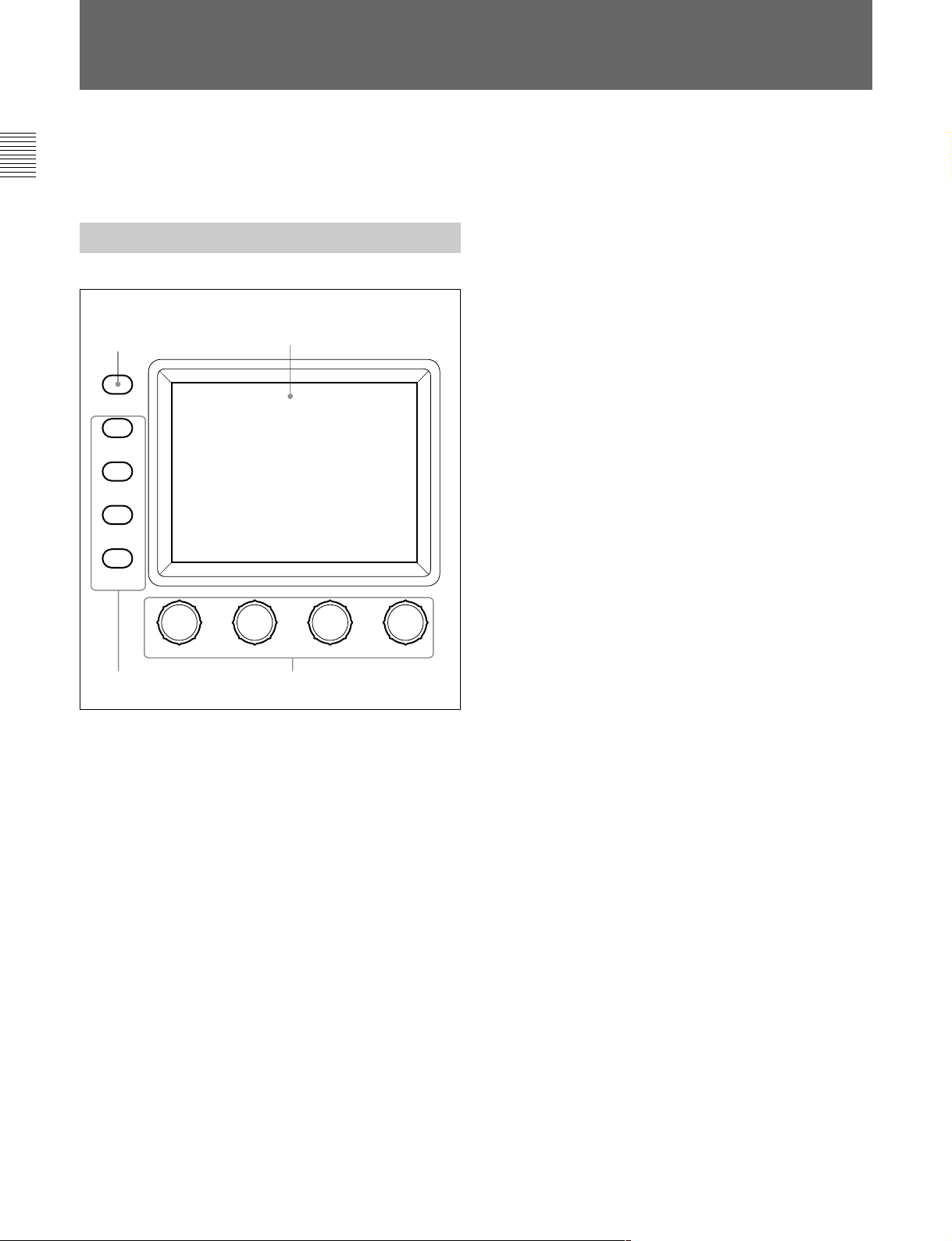
Locations and Functions of Parts
Operation Panel
3 PANEL ACTIVE button
4 STANDARD button
5 Spare button
6 Test signal output select buttons
2 MEMORY STICK lamp
1 Memory Stick slot
Rubber cap
7 CLOSE button
8 VTR START/STOP button
9 VTR playback control
buttons
PAN EL
STANDARD TEST BARS CLOSE
ACTIVE
MEMORY
STICK
MONITOR
FUNCTION
VF DISP
MAINTENANCE
VF MENU
SCENE
CANCEL
PAI NT
ENTER
ALARM
MENU SELECT
qa Menu operation block
0 ALARM indicator
1 Memory Stick slot
Insert a Memory Stick to store setting data, such as
reference files and scene files of the video camera or
camera control unit.
2 MEMORY STICK (Memory Stick access)
lamp
The lamp shows the status of the Memory Stick.
Off: No Memory Stick is inserted.
Lit in green: There is a Memory Stick in the slot.
In this condition, you can safely eject the Memory
Stick.
Lit in red: Data are being read/written. If you eject
the Memory Stick in this condition, the data are
not guaranteed. All the data may be lost.
For details on Memory Sticks, see page 24(E).
VTR
START/STOP
ABB
AWB
WHITE
BLACK
IRIS/MB
AUTO
IRIS
EXT
IRIS
REMOTE CONTROL UNIT RM-B750
MASTER
ACTIVE
BLACK
qd White balance/black
balance control block
qs Iris/master black control block
3 PANEL ACTIVE button
Press to select the control mode for the connected
camera system. Each time you press the button with
the factory setting, the control mode cyclically
switches among FULL, PART, and LOCK modes.
FULL mode: All controls from this unit are enabled
(panel active status). Both this button and the
IRIS/MB ACTIVE indicator in the iris/master
black control block light.
PART mode: Controls only from the iris/master black
control block are enabled (iris/master black active
status). This button goes dark, but the IRIS/MB
ACTIVE indicator stays lit.
LOCK mode: All controls from this unit are disabled
(lock status). Both this button and the IRIS/MB
ACTIVE indicator in the iris/master black control
block go dark.
4(E)
Page 35

Using the RM Configuration menu under the
Maintenance menu, the function of this button can be
changed to switch only between FULL and LOCK
modes
(see page 19(E)).
The RM Configuration menu operation is possible in
any mode.
9 VTR playback control buttons
Controls VTR playback operations.
s (stop) button
Press to stop a rewind, fast-forward or playback
operation.
4 STANDARD button
When you press this button, the video camera is
initialized to its standard state, and the button lights for
several seconds.
If you press the button while lit, the video camera
retrieves the state before the button was lit.
5 Spare button
For future use.
6 Test signal output select buttons
Press and light up one of these buttons to activate the
test signal generator of the video camera and send the
respective signals.
TEST: To send a signal to test the video circuits.
You can select the kind of the test signal to be
output using the RM Configuration menu under the
Maintenance menu
(see page 19(E)).
BARS: To send a color bar signal
Note
The BARS button takes priority to the TEST button. If
the BARS button is lit, press the button to turn it dark
before pressing the TEST button.
7 CLOSE button
Press and light the button to close the iris. To release
the close mode, press the button again so that it goes
dark.
j (rewind) button
Press and light this button to start a rewind operation.
G (play) button
Press and light this button to start a playback
operation.
J (fast forward) button
Press and light this button to start a fast-forward
operation.
7 (recording review) button
Press and light this button to execute a recording
review operation.
Notes
•When the VTR START/STOP button is lit, these
buttons are deactivated. To activate the buttons, first
press the VTR START/STOP button to cancel
Recording mode.
•A part of the VTR control functions of this unit may
be disabled depending on the combination of camera
and VTR. For details, ask your Sony dealer.
0 ALARM indicator
Flashes or lights in red when trouble occurs in the
camera system and the self-diagnostic function
activates at the video camera or the camera control
unit.
8 VTR START/STOP button
Press and light up this button to start a recording
operation. When you press the button when lit, it goes
dark, and recording stops.
Using the RM Configuration menu under the
Maintenance menu, you can assign the CALL button
function to this button
(see page 19(E)). In this case,
press to send a call signal to the video camera, on
which the CALL button lights. The tally lamps on the
camera and the red tally lamp on the camera control
unit light when not lit, or go dark when lit.
When the CALL button on the video camera is
pressed, the button on this unit lights and a buzzer
sounds.
5(E)
Page 36

Locations and Functions of Parts
qa Menu operation block
A RM menu select/camera
menu set buttons
MONITOR
FUNCTION
VF DISP
MAINTENANCE
VF MENU
SCENE
CANCEL
PAINT
ENTER
MENU SELECT
B LCD/touch panel
C Control knobs
A RM menu select/camera menu set buttons
MONITOR: When this button is unlit, you can
select the menus of this unit using the other
buttons (RM Menu mode in which the functions
indicated with white letters for the buttons are
valid).
Press and light this button to display the video
signal (SDTV signal only) from the connected
camera on the LCD. This also permits the menus
of the camera to be operated from this unit (the
functions indicated with blue letters for the
buttons and the leftmost control knob are valid).
FUNCTION/VF DISP (viewfinder display): With
the MONITOR button unlit, the Function menu of
this unit appears on the LCD when you press and
light this button.
With the MONITOR button lit, the character
display of the camera is turned on when you press
and light this button.
MAINTENANCE/VF MENU (viewfinder menu):
With the MONITOR button unlit, the
Maintenance menu of this unit appears on the
LCD when you press and light this button.
With the MONITOR button lit, the unit enters
Camera Menu mode when you press and light this
button. The main menu of the camera appears on
the LCD.
SCENE/CANCEL: With the MONITOR button
unlit, the Scene File menu of this unit appears on
the LCD when you press and light this button.
With the MONITOR button lit, you can cancel the
setting of the camera menu item selected on the
LCD by pressing this button.
PAINT/ENTER: With the MONITOR button unlit,
the Paint menu of this unit appears on the LCD
when you press and light this button.
With the MONITOR button lit, you can register
the setting of the camera menu item selected on
the LCD by pressing this button.
When none of the buttons are lit, the status display
(page 10(E)) is obtained.
For the items of each menu, see “Menu Items” on page 14(E).
For details on the camera menus, refer to the Operation
Manual or the System Manual for the camera.
B LCD/touch panel
Normally displays the statuses (see page 10(E)).
When you press and light the MONITOR button, it
displays the video signal from the connected camera
(SDTV signal only. HDTV signal will not be
displayed.).
In RM Menu or Camera Menu mode, the selected
menu is displayed to permit you to operate the menu.
C Control knobs (rotary encoders)
In RM Menu mode, adjust the selected items on the
touch panel.
In Camera Menu mode, select and adjust the menu
items using the leftmost knob.
6(E)
Page 37

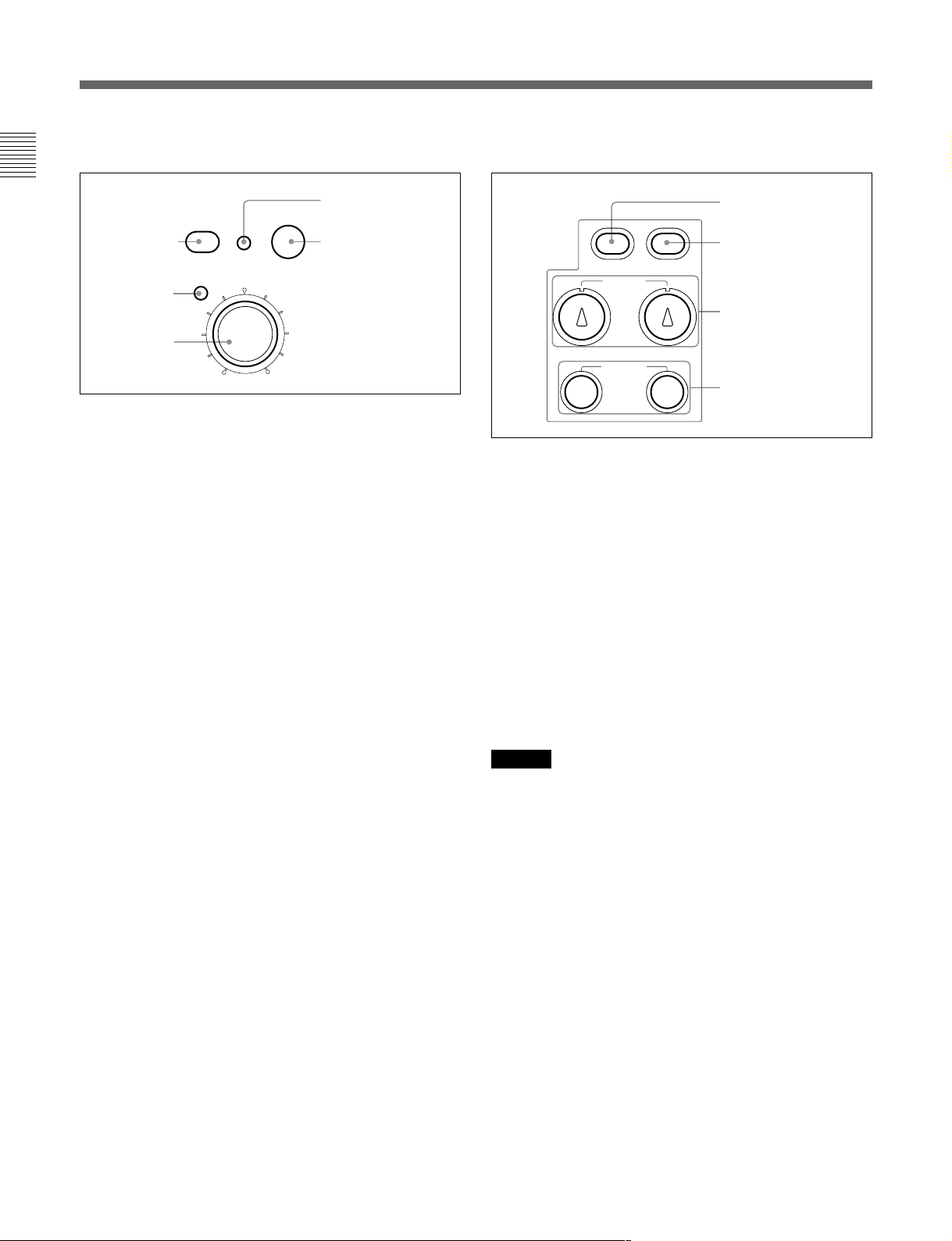
qs Iris/master black control block
qd White balance/black balance control block
D IRIS/MB ACTIVE
indicator
A AUTO IRIS
button
B EXT indicator
C IRIS control
AUTO
IRIS
EXT
IRIS
IRIS/MB
ACTIVE
MASTER
BLACK
E MASTER BLACK
control
A AUTO IRIS button
Press and light the button to automatically adjust the
iris according to the amount of input light.
If you press the button when lit, it goes dark, and
manual iris adjustment is enabled.
B EXT (lens extender) indicator
Lights when the lens extender is used on the connected
camera.
C IRIS control
When the AUTO IRIS button is not lit, you can adjust
the iris manually by turning the control.
When the AUTO IRIS button is lit, you can fine-adjust
the reference value for automatic iris adjustment in a
range of ±2f with this control.
The adjustment mode of this control is specified at the
factory as Absolute mode, which can also be changed
to Relative mode using the RM Configuration menu
under the Maintenance menu
(see page 19(E)).
D IRIS/MB ACTIVE (iris/master black active)
indicator
Lights when the control mode is set as FULL or PART
mode with the PANEL ACTIVE button. When this
indicator is lit, iris/master black controls from this unit
are enabled.
E MASTER BLACK control
Manually adjusts the master black level.
The adjustment mode of this control is specified at the
factory as Relative mode, which can be changed to
Absolute mode using the RM Configuration menu
under the Maintenance menu
(see page 19(E)).
A AWB button
B ABB button
AWB
WHITE
BLACK
ABB
C WHITE controls
D BLACK controls
A AWB (auto white balance) button
Press to automatically adjust the white balance.
The button lights during adjustment and goes dark
when adjustment is completed.
If you press this button when lit, the automatic
adjustment is canceled, and the button flashes. To stop
the flashing, press the button again.
B ABB (auto black balance) button
Press to automatically adjust the black balance and
black set.
The button lights during adjustment and goes dark
when adjustment is completed.
If you press this button when lit, the automatic
adjustment is canceled, and the button flashes. To stop
the flashing, press the button again.
Note
When the adjustment mode of the BLACK controls is
specified as Absolute mode, automatic black balance
adjustment with ABB button is disabled.
C WHITE (white balance) controls
Adjust the R/B white balance.
The adjustment mode of these controls is specified at
the factory as Relative mode, which can be changed to
Absolute mode using the RM Configuration menu
under the Maintenance menu
(see page 19(E)).
D BLACK (black balance) controls
Adjust the R/B black balance.
The adjustment mode of these controls is specified at
the factory as Relative mode, which can be changed to
Absolute mode using the RM Configuration menu
under the Maintenance menu
(see page 19(E)).
7(E)
Page 38

Locations and Functions of Parts
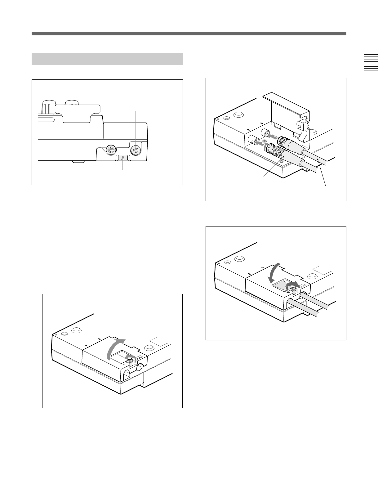
Connector Panel
1 CAMERA connector
2 MONITOR
connector
Cover fixing screw
1 CAMERA connector (8-pin)
Connect to the camera using the supplied remote
control cable.
2 MONITOR connector (BNC)
Connect to a color monitor to observe the signal from
the camera.
2 Connect the remote control cable to the CAMERA
connector and the BNC cable to the MONITOR
connector.
CAMARA
MONITOR
BNC cable (sold separately)
Remote control cable
(supplied)
3 Close the cover and secure the screw.
Connections
1 Loosen the cover fixing screw on the bottom and
open the cover.
C
A
M
A
R
A
M
O
N
IT
O
R
C
A
M
A
R
A
M
O
N
IT
O
R
8(E)
Page 39

Menu Configuration and Basic Menu Operations
The RM-B750 provides menu operations for various
functions such as adjustments of system equipment.
Basic Operating Procedure
Unlit when setting the
menus of this unit.
MONITOR
FUNCTION
VF DISP
MAINTENANCE
VF MENU
SCENE
CANCEL
PAINT
ENTER
MENU SELECT
2
2 Select the item to be adjusted.
Press the button that shows the name of the item on
the menu to obtain the corresponding adjustment
display or operation area.
When the selected menu is composed of
multiple pages
With the menu that is composed of multiple pages
such as Paint menu, press v or V to flip the pages.
See “Initial display (Paint menu)” on the next page.
When a submenu is shown
Press the desired submenu item to change the
display.
See “Submenu” on page 11(E).
3 Set or adjust the item (parameters).
• Turn the control knobs (or press the button) to
adjust (or set) the corresponding item
(parameters) to the desired values.
See “Adjustment display” on page 11(E).
• When a message is displayed, follow the
instruction and press
[OK].
1
3
When all the menu select buttons are not lit, the status
display (see the next page) is obtained.
1 To display a menu of this unit, press and light one
of the menu select buttons.
The menu operation mode is initiated and the menu
for the pressed button appears on the display.
FUNCTION: Function menu
See page 13(E) for the display configuration and page
20(E) for the menu items.
MAINTENANCE: Maintenance menu
See page 18(E) for the menu items and page 21(E) for
adjustments.
SCENE: Scene file operation menu
See page 12(E) for the display configuration and
operation.
PAINT: Paint menu
See page 10(E) for the display configuration and page
14(E) for the menu items.
When the adjustment is finished
• To adjust another item of the same menu, press the
names of that item.
• To adjust items of another menu, press the
corresponding menu select button.
• To release the menu operation mode, press the lit
menu select button.
• You may select Function menu without exiting the
currently selected menu. When you exit Function
menu by either of the following methods, the
previous menu is restored.
– Press the lit FUNCTION button so that it goes dark.
– Press the lit menu select button for the previous
menu.
9(E)
Page 40

Menu Configuration and Basic Menu Operations
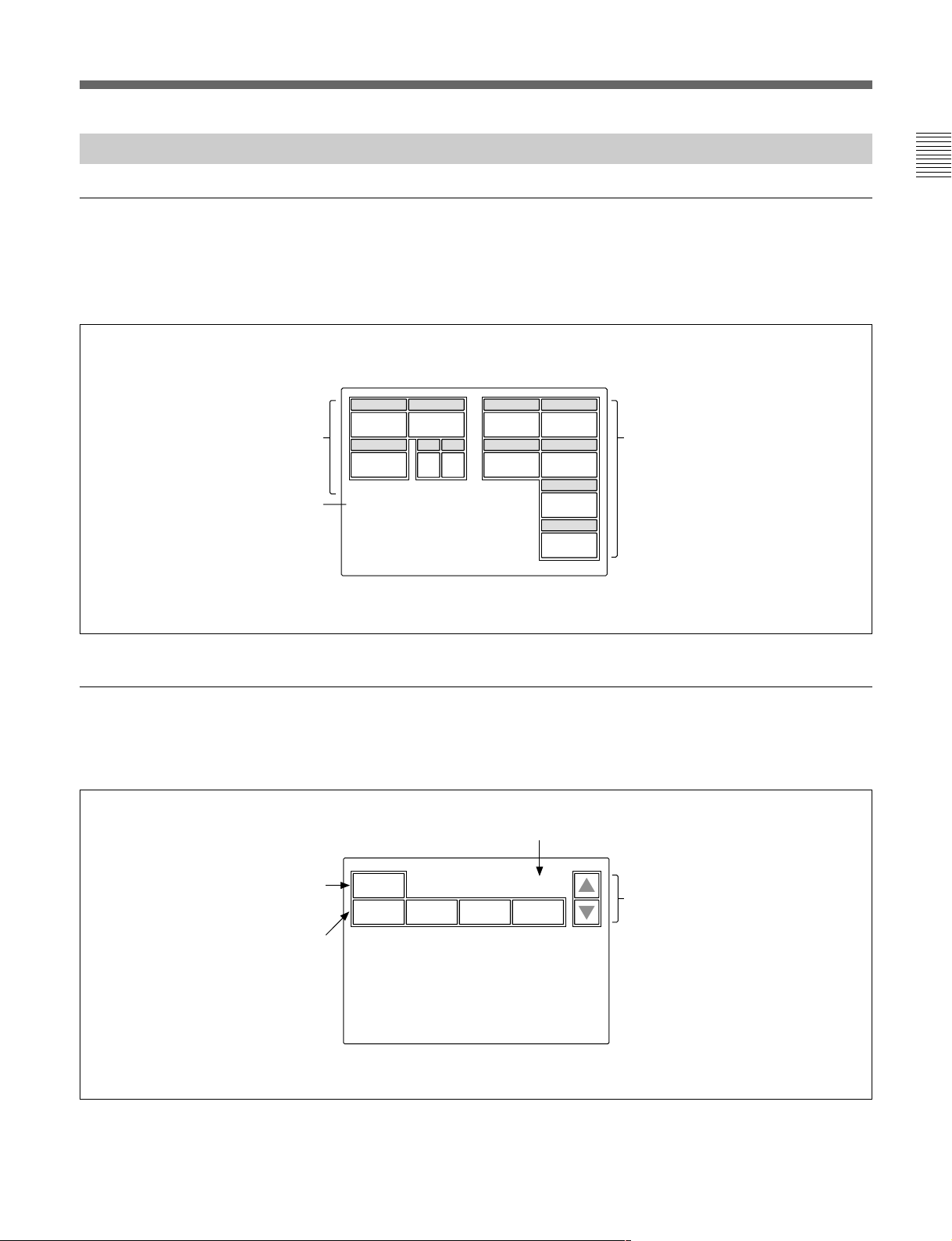
Basic Configuration of Menu Display
Status display
When you do not select any of the Menu select buttons
(FUNCTION, MAINTENANCE, SCENE, PAINT) of
the menu operation block (all unlit), the LCD shows
the following status display:
On the status display, each item is
only displayed. The setting is made
with the menu or with the
corresponding knob on the
operation panel.
You may set these items using
the Function menu.
The file number selected with
the Scen File Operation menu is
displayed.
Shutter
60 0dB
Gamma
0.45
White Mem : A
Scene File : 1
M. Gain
ND
1
ND
A
White
00
Black
0
0
M. Blk
0
Iris
CL
You may adjust these items using the
WHITE knobs, BLACK knobs, MASTER
BLACK knob or IRIS knob.
Initial display (Paint menu)
When you press and light the PAINT button of the
menu operation block, the Paint menu display is
obtained.
The Paint menu consists of 8 pages.
Example: Initial display of page 2
To clear the adjusted values
The names of the items are
displayed. Press the name
of the item to be adjusted.
The color of the pressed
name area will change, and
the lower half of the panel
will become the adjustment
display (see the next page).
Clear
White Black Flare Gamma
Current page number / total number of pages
2 / 8
Press either to flip the pages (1 to 8)
of the menu.
10(E)
Page 41

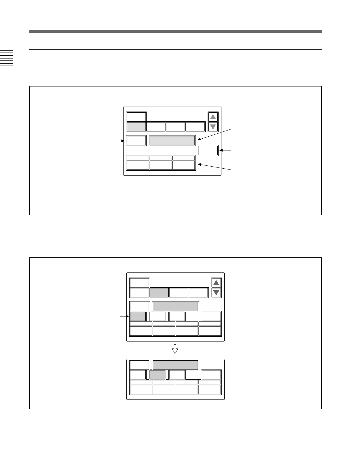
Adjustment display (Paint menu)
When you select an item on the initial display of the
Paint menu, the lower half of the panel becomes the
adjustment display for the selected item.
Example: when you select “White” from the initial display of page 2
Clear
White Black Flare Gamma
When you press this, the upper
half of the panel becomes the
WF/PIX
Select
White
monitor output setting display
(see the next page).
R
0
G
0
B
0
Submenu
If the selected item has many parameters, a submenu is
displayed.
Example: when you select “Skin Detail” from the initial display of page 3
2 / 8
ATW
The name of the item selected on the
initial display is displayed.
If you press this area after pressing
[Clear], all the adjustment values for the
selected item are initialized to standard.
When there are any ON/OFF functions
related to the adjustment, the names of
the functions are displayed on this line.
The adjustment parameters for the
selected item and their adjustment
values are displayed.
You may adjust these items using the
corresponding control knobs.
If you press a value area after
pressing [Clear], that adjustment value
is initialized to standard.
Submenu
Clear
V Mod
Saw
WF/PIX
Select
Skin
Detail
Sat
Skin Detail
123
Level
WF/PIX
Select
Phase
0
Width
0
Skin Detail
123
Level
Phase
0
Width
0
2 / 8
Black
Gamma
Skin
DTL 1
Sat
0
0
Press to switch the parameters.
Skin
DTL 2
Sat
0
0
11(E)
Page 42

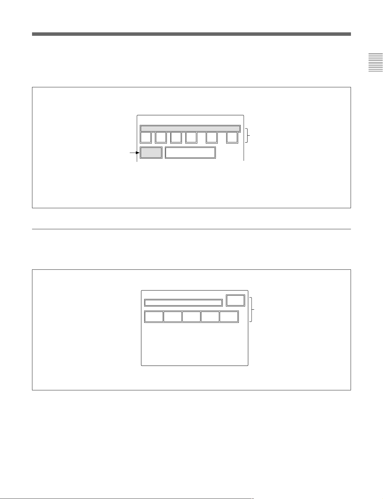
Menu Configuration and Basic Menu Operations
Monitor output set display (Expansion menu)
When you press
display of the Paint menu, the upper half of the panel
becomes the monitor output setting display.
[WF/PIX Select] on an adjustment
WF/PIX Monitor Select
R G B RGB SEQ ENC
Press again to return to
the previous display.
WF/PIX
Select
Scene File Operation menu display
When you press and light the SCENE button of the
menu operation block, the Scene File Operation menu
display is obtained.
R/G/B: To independently select the R,
G, or B signal.
RGB: To select the R, G, and B signals
in combination.
SEQ: Only the WF output is enabled,
and you can monitor the waveforms of
the R, G, and B signals in sequence.
ENC: The encoded signal is output.
To recall a scene file:
Press the number of the desired
scene file, and the settings stored
in the corresponding scene file
will be retrieved.
The color of the number of the
retrieved file changes.
When you press the same
number again, the previous
condition will be restored.
12(E)
Scene File Recall
Store
12345
To store the current settings
in a scene file:
First press and light [Store], then select
the desired scene file number.
When file registration is finished, [Store]
returns to its original color.
Page 43

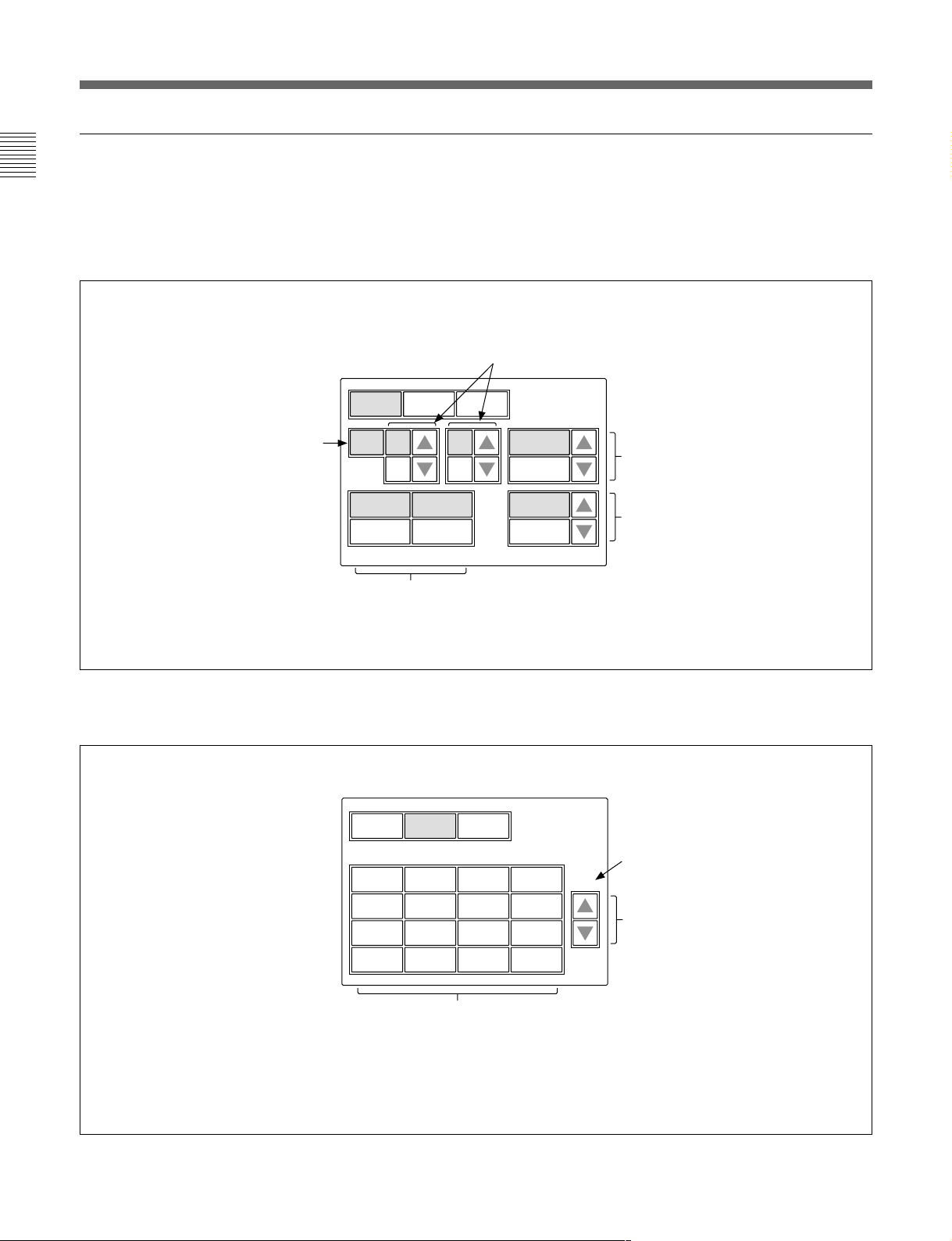
Function menu displays
When you press and light the FUNCTION button of
the menu operation block, the Function menu display
is obtained.
When “Operation” is selected
Press v or V to select the desired filter.
The number of ND and CC filters you may select
depends on the camera.
Press [Filter Ctrl] and change its
color to enable filter selection
from this display.
When “SW” is selected
Opera-
tion
Filter
Ctrl
SW WHITE
ND GammaCC
1 A 0.45
Shutter ECS
Master
Gain
60 30.00 0dB
You may adjust these items using the
corresponding control knobs.
Opera-
tion
S-Skin
Knee
Sat Mono
Black
Gamma
5600K
SW WHITE
Low Key
Sat
Aperture
Auto
Knee
ATW PsF
Knee
Skin
Detail
Knee
Sat
Detail
Gate
Press v or V to set the gamma value.
You may change it in ±0.05 steps.
Press v or V to set the master gain.
The value increases when v is pressed
and decreases when V is pressed.
Current page number /
total number of pages
1 / 2
Press either to flip the pages of
the menu.
These buttons turn on and off the
corresponding functions.
Any button whose designation includes “Off”
turns the respective function OFF when you
light it. Other buttons turn the respective
functions ON when you light them.
13(E)
Page 44

Menu Configuration and Basic Menu Operations
Menu Items
The “Control items” marked with z are those assigned
to the control knobs. The other items are operated on
the menu display.
Paint menu
Paint menu consists of pages 1 to 8.
Pressing v or V of each page flips pages 1 through 8
in sequence.
Page Menu Submenu Control item Function
SD
a)
z Level Adjusts the HD detail level.
z Limiter Adjusts the HD detail limiter.
z Crispening Adjusts the HD detail crispening.
z Level Dep Adjusts the HD level dependence.
Detail Off Turns the HD detail ON/OFF.
SD DTL Off Turns the SD detail ON/OFF.
a)
z Level Adjusts the SD detail level.
z Limiter Adjusts the SD detail limiter.
z Crispening Adjusts the SD detail crispening.
z Level Dep Adjusts the SD level dependence.
Detail Off Turns the HD detail ON/OFF.
SD DTL Off Turns the SD detail ON/OFF.
z Phase Adjusts the skin detail phase.
z Width Adjusts the skin detail width.
z Saturation Adjusts the skin detail saturation.
DTL Gate # Turns the skin detail gate ON/OFF (each channel).
Auto Hue # Executes the skin detail auto hue setup (each channel).
Skin DTL # Turns the skin detail ON/OFF (each channel).
Flare Off Turns the flare ON/OFF.
z Blk Gamma Adjusts the master black gamma.
z Knee Point Adjusts the master knee point.
z Knee Slope Adjusts the master knee slope.
Gamma Off Turns the gamma ON/OFF.
Knee Off Turns the knee ON/OFF.
ATW Executes the auto-trace white balance adjustment.
Flare Off Turns the flare ON/OFF.
Gamma Off Turns the gamma ON/OFF.
Paint 1/8 Detail 1 HD
Skin Detail 1/2/3 (common) z Level Adjusts the skin detail level.
Flare z R/G/B Adjusts the flare balance.
Gamma/Knee z Gamma Adjusts the master gamma.
Paint 2/8 White z R/G/B Adjusts the white balance.
Black z R/G/B/Master Adjusts the black balance.
Flare z R/G/B Adjusts the flare balance.
Gamma z R/G/B/Master Adjusts the gamma.
a) The submenu to select HD or SD is displayed only when an HD camera is connected.
14(E)
Page 45

Page Menu Submenu Control item Function
Paint 3/8 V Mod Saw z R/G/B/Master Adjusts the V modulation.
V Mod Saw Off Turns the V modulation ON/OFF.
Skin Detail 1/2/3 (common) z Level Adjusts the skin detail level.
z Phase Adjusts the skin detail phase.
z Width Adjusts the skin detail width.
z Saturation Adjusts the skin detail saturation.
DTL Gate # Turns the skin detail gate ON/OFF (each channel).
Auto Hue # Executes the skin detail auto hue setup (each channel).
Skin DTL # Turns the skin detail ON/OFF (each channel).
Saturation z Saturation Adjusts the saturation.
Saturation Turns the saturation ON/OFF.
Black Gamma RGB z R/G/B/Master Adjusts the black gamma.
Y z Y Adjusts the black gamma.
Paint 4/8 Detail 1 HD
a)
z Level Adjusts the HD detail level.
z Limiter Adjusts the HD detail limiter.
z Crispening Adjusts the HD detail crispening.
z Level Dep Adjusts the HD level dependence.
Detail Off Turns the HD detail ON/OFF.
SD DTL Off Turns the SD detail ON/OFF.
a)
SD
z Level Adjusts the SD detail level.
z Limiter Adjusts the SD detail limiter.
z Crispening Adjusts the SD detail crispening.
z Level Dep Adjusts the SD level dependence.
Detail Off Turns the HD detail ON/OFF.
SD DTL Off Turns the SD detail ON/OFF.
Detail 2 HD
a)
z H/V Ratio Adjusts the HD detail H/V ratio.
z Frequency Adjusts the HD detail boost frequency.
z Mix Ratio Adjusts the HD detail mix ratio.
z Comb Adjusts the HD detail comb.
Detail Off Turns the HD detail ON/OFF.
SD DTL Off Turns the SD detail ON/OFF.
a)
SD
z H/V Ratio Adjusts the SD detail H/V ratio.
z Frequency Adjusts the SD detail boost frequency.
z Mix Ratio Adjusts the SD detail mix ratio.
z Comb Adjusts the SD detail comb.
Detail Off Turns the HD detail ON/OFF.
SD DTL Off Turns the SD detail ON/OFF.
Detail 3 HD
a)
z W.Limiter Adjusts the HD detail white limiter.
z B.Limiter Adjusts the HD detail black limiter.
z Fine Adjusts the HD fine detail level.
z Knee Apert Adjusts the HD knee aperture.
Fine Detail Turns the HD fine detail ON/OFF.
Knee Aperture Turns the HD knee aperture ON/OFF.
a)
SD
z W.Limiter Adjusts the SD detail white limiter.
z B.Limiter Adjusts the SD detail black limiter.
z Coring Adjusts the coring for SD cross color reduction.
z Level Adjusts the level for SD cross color reduction.
Crs Col Reduce Turns the cross color reduction ON/OFF.
a) The submenu to select HD or SD is displayed only when an HD camera is connected.
15(E)
Page 46

Menu Configuration and Basic Menu Operations
Page Menu Submenu Control item Function
Paint 4/8 Cross Color Suppression z CCS Level Adjusts the level for cross color suppression.
(Continued)
Paint 5/8 Knee Point z R/G/B/Master Adjusts the knee point.
Knee Slope z R/G/B/Master Adjusts the knee slope.
Matrix Matrix 1 z R-G/G-B/B-R Adjusts the matrix coefficients.
Matrix 2 z R-B/G-R/B-G Adjusts the matrix coefficients.
Multi Matrix z Phase Adjusts the multi matrix phase.
Paint 6/8 Gamma/Knee z Gamma Adjusts the master gamma.
Knee Saturation z Knee Point Adjusts the master knee point.
Low Key Saturation z Level Adjusts the low key saturation level.
White Clip z R/G/B/Master Adjusts the white clip.
Paint 7/8 Gamma Table z Standard Adjusts the gamma table.
Auto Knee z Point Limit Adjusts the point limit for auto knee.
z N. Level Adjusts the notch level.
z Frequency Adjusts the notch frequency.
CCS Turns the cross color suppression ON/OFF.
Knee Off Turns the knee ON/OFF.
Knee Off Turns the knee ON/OFF.
User Matrix Turns the user matrix ON/OFF.
Preset Matrix Turns the preset matrix ON/OFF.
Matrix Off Turns all the matrixes ON/OFF.
User Matrix Turns the user matrix ON/OFF.
Preset Matrix Turns the preset matrix ON/OFF.
Matrix Off Turns all the matrixes ON/OFF.
z Hue Adjusts the multi matrix hue.
z Sat Adjusts the multi matrix saturation.
Multi Matrix Turns the multi matrix ON/OFF.
Matrix Off Turns all the matrixes ON/OFF.
All Clear Clears all the matrix settings.
z Blk Gamma Adjusts the master black gamma.
z Knee Point Adjusts the master knee point.
z Knee Slope Adjusts the master knee slope.
Gamma Off Turns the gamma ON/OFF.
Knee Off Turns the knee ON/OFF.
z Knee Slope Adjusts the master knee slope.
z Level Adjusts the knee saturation.
Knee Off Turns the knee ON/OFF.
Knee Sat Turns the knee saturation ON/OFF.
Low Key Sat Turns the low key saturation ON/OFF.
White Clip Off Turns the white clip ON/OFF.
z User Adjusts the user gamma table.
Standard Selects the standard gamma table.
User Selects the user gamma table.
Gamma Off Turns the gamma ON/OFF.
z Auto Slope Adjusts the knee slope for auto knee.
Adaptive Turns the adaptive highlight control for auto knee ON/OFF.
Knee Off Turns the knee ON/OFF.
16(E)
Page 47

Page Menu Submenu Control item Function
Paint 7/8 Auto Iris z Phase Adjusts the skin tone auto iris phase.
(Continued)
z Width Adjusts the skin tone auto iris width.
Normal Mode Selects Normal mode for auto iris.
Skin Mode Selects Skin mode for auto iris.
Iris Auto Hue Executes the auto hue.
Auto Iris Gate Turns the skin tone auto iris gate ON/OFF.
ECS/S-EVS z Shutter Adjusts the shutter speed.
z ECS Adjusts the ECS frequency.
z S-EVS Adjusts the Super EVS.
Shutter Turns the shutter mode ON/OFF.
ECS Turns the ECS mode ON/OFF.
S-EVS Turns the Super EVS mode ON/OFF.
Paint 8/8 SD Gamma z SD Gamma Adjusts the SD gamma.
z Blk Gamma Adjusts the black gamma.
z M Gamma Adjusts the master gamma.
Gamma Off Turns the gamma ON/OFF.
Cross Color Reduce z Comb Adjusts the comb for cross color reduction.
z Coring Adjusts the coring for cross color reduction.
z Level Adjusts the level for cross color reduction.
Crs Col Reduce Turns the cross color reduction ON/OFF.
17(E)
Page 48

Menu Configuration and Basic Menu Operations
Maintenance menu
Menu 2ndary menu Submenu Control item Function
Adjusting Black Shading R/G/B z H Saw/H Para/V Saw/V Para Adjusts the black shading.
Auto B Shading Executes the auto black shading.
White Shading R/G/B z H Saw/H Para/V Saw/V Para Adjusts the white shading.
Auto W Shading Executes the auto white shading.
Phase H Phase z H Step Adjusts the H phase.
z H Coarse
z H Fine
SC Phase z SC Adjusts the SC phase.
z BF Adjusts the black burst signal phase.
Auto Iris z (patterns) Selects the Auto Iris patterns.
z Level Adjusts the auto iris level.
z APL Ratio Adjusts the auto iris APL ratio.
z Iris Gain Adjusts the auto iris gain.
Auto Setup Auto White Performs automatic white balance adjustment.
Auto Black Performs automatic black balance adjustment.
Auto White Shading Performs automatic white shading adjustment.
Auto Black Shading Performs automatic black shading adjustment.
Auto Level Performs automatic level adjustment.
Auto Hue Skin Detail 1 Performs the corresponding automatic skin detail auto hue
Skin Detail 2 adjustment.
Skin Detail 3
Skin Auto Iris Performs skin tone auto iris adjustment.
Camera Config Preset Matrix SMPTE-240M Sets the preset matrix.
ITU-709
SMPTE Wide
NTSC
EBU
ITU-601
RM Config RM Adjusting Buzzer Volume z Call Adjusts the volume of the call buzzer.
z Touch Adjusts the volume of the response sound of the touch panel.
z Switch Adjusts the volume of the confirmation sound of self-
illuminating switches.
z Master Adjusts the total buzzer sound volume.
Call Buzzer Turns the call buzzer ON/OFF.
Touch Click Turns the response sound of the touch panel ON/OFF.
SW Click Turns the confirmation sound of switches ON/OFF.
All Off Turns all the buzzers ON/OFF.
LED Brightness z Switch Adjusts the brightness of the corresponding LEDs.
z Other
z Master Adjusts the master brightness of the LEDs.
18(E)
Page 49

Menu 2ndary menu Submenu Control item Function
RM Config Date/Time Date z Year Adjusts the date for the built-in clock of this unit.
(Continued)
z Month
z Day
Set
Cancel
Time z Hour Adjusts the time for the built-in clock of this unit.
z Minute
z Second
Set
Cancel
SW Setting Active Mode Setting Active Mode Switches the mode of the PANEL ACTIVE button.
Mode 2: FULL/LOCK
Mode 3: FULL/PART/LOCK.
TEST TEST Mode Select the signal to be output when pressing the TEST
button (Saw, 3STEP, 10STEP).
VTR START/STOP SW Mode Switches between VTR and CALL functions.
Cable Comp Length Sets the cable compensation value when using video signals.
VR Setting White R/B ABS/REL Switches between Absolute and Relative modes for manual
white adjustment.
Scale Selects the variable range of the white level in relative mode
(1/1, 1/2, 1/4).
Black R/B ABS/REL Switches between Absolute and Relative modes for manual
black adjustment.
Scale Sets the variable range of the black level in Relative mode
(1/1, 1/2, 1/4).
Master Black ABS/REL Switches between Absolute mode and Relative mode for
master black adjustment.
Scale Selects the variable range of the master black level in
Relative mode (1/1, 1/2, 1/4).
IRIS ABS/REL Switches between Absolute mode and Relative mode for
manual iris adjustment.
z Min Sets the minimum iris level.
z Max Sets of the maximum iris level.
Information Displays the software version of this unit.
Security Sets the security requirements of this unit.
LCD LCD Brightness z Bright Adjusts the brightness of the LCD of this unit.
File Reference File Store Stores a reference file.
Reference File Transfer CAM t MS Transfers a reference file (from a camera to a Memory
Stick).
MS t CAM Transfers a reference file (from a Memory Stick to a
camera).
Scene File Transfer CAM t MS Transfers a scene file (from a camera to a Memory Stick).
MS t CAM Transfers a scene file (from a Memory Stick to a camera).
OHB File Store Stores a OHB file.
Super Motion Field Rate [ x1, x3 ] Sets the field rate when using a Super-Motion camera.
Frame Interpolation [ OFF, A, B, C ] Sets the pattern to make the reference output picture in
3-times mode
Flicker Reduction [ OFF, Normal, Strong ] Sets the flicker suppression in 3-times mode.
Memory Stick Memory Stick Format Formats a Memory Stick.
19(E)
Page 50

Menu Configuration and Basic Menu Operations
Function menu
Menu Submenu Control item Function
Operation Filter Ctrl Selects the filter remote or local mode.
ND (1/2/3/4/5) Selects ND filters.
CC (A/B/C/D/E) Selects CC filters.
Gamma Selects the step gamma.
Master Gain Selects the master gain.
Shutter Turns the shutter mode ON/OFF.
ECS Turns the ECS mode ON/OFF.
z Shutter Selects the shutter speed.
z ECS Selects the ECS frequency.
SW page 1 5600K Turns 5600K electric color temperature conversion function ON/OFF.
Auto Knee Turns the auto knee function ON/OFF.
When this button is in inverse video (ON), the knee point is automatically adjusted according to
the light content of the picture.
Skin Detail Turns the skin detail function ON/OFF.
Detail Gate Skin tone detail gate function.
When this button is in inverse video (ON), the adjustment range of the skin tone detail is
displayed in white on the monitor screen.
Black Gamma Turns the black gamma function ON/OFF.
Knee Aperture Turns the knee aperture function ON/OFF.
Knee Sat Turns the knee saturation function ON/OFF.
Sat Turns the saturation function ON/OFF.
Mono Turns the mono color function ON/OFF. This function mixes the chroma signals of a single hue
to the luminance signal. The chroma level is modulated according to the luminance signal.
S-Skin Knee Turns the Super-skin knee function ON/OFF.
Low Key Sat Turns the function to compensate the chroma level in dark areas ON/OFF.
ATW Turns the auto-tracing white function ON/OFF.
PsF Turns the CCD progressive read function ON/OFF.
page 2 Knee Off Turns the knee compensation function ON/OFF (OFF when lit).
Gamma Off Turns the gamma function ON/OFF (OFF when lit).
Detail Off Turns the detail compensation function ON/OFF (OFF when lit).
Matrix Off Turns the linear matrix function to enhance color fidelity ON/OFF (OFF when lit).
White Clip Off Turns the limiter function for highlight signals ON/OFF (OFF when lit).
Level Dep Off Turns the level dependence which controls the details in the dark part of a picture ON/OFF
(OFF when lit).
Chroma Off Turns the chroma function ON/OFF (OFF when lit).
SD Detail Off Turns the detail function for SD output ON/OFF with a HDTV camera connected
(OFF when lit).
SD Matrix Off Turns the linear matrix function for SD output ON/OFF wit a HDTV camera connected
(OFF when lit).
WHITE Preset Selects the preset white balance setting.
Memory A Selects the white balance setting in memory A.
Memory B Selects the white balance setting in memory B.
20(E)
Page 51

Initial Settings
Setting the Operating Conditions of the RM-B750
By using the RM Configuration menu or LCD setting
display, you can set the built-in clock of the RM-B750
and adjust various conditions of the RM-B750, such as
the sound volume of the warning buzzer and the
brightness of the indicators and LCD.
To display the RM Configuration menu/
LCD setting display
Proceed as follows:
Unlit when setting the
menus of this unit.
FUNCTION
1
MAINTENANCE
MONITOR
VF DISP
VF MENU
SCENE
CANCEL
Adjusting File
RM
Config
Maintenance Menu
Auto
LCD
Camera
Config
Setup
Super
Motion
Memory
Stick
2
To obtain the LCD setting display, press [LCD].
The LCD setting display
(page 23(E)) appears.
Setting the Built-in Clock
The RM-B750 has a built-in clock to record the date
and time when reference and scene files are saved to
Memory Sticks.
To set the clock, proceed as follows:
1 Press [Date/Time] on the RM Configuration menu.
The current setting is displayed on the Date/Time
Set menu.
Date Time Set Menu
Date Time
2001/11/17
(Sat)
: 12 :
31
22
Exit
PAINT
ENTER
MENU SELECT
1 Press to light the MAINTENANCE button of the
menu operation block.
The Maintenance Menu appears.
2 To display RM Configuration menu, press
[RM Config].
The RM Configuration menu appears.
RM
Adjusting
Cable
Comp
RM Config Menu
SW
SettingVRSetting
Exit
Infor-
mation
Date
Time
Secu-
rity
2 To set the date:
1)Press and light
Date Time
Year
2001
2)Set the Year, Month and Day with the left three
control knobs.
3)Press
[Set].
The set date becomes valid.
To restore the previous setting, press
instead of [Set].
[Date].
Date Time Setting
2001/11/17
(Sat)
22 : 12 : 31
Set Cancel
Month
Day
8
Exit
8
[Cancel]
21(E)
Page 52

Initial Settings
3 To set the time:
1)Press and light
Date Time
Hour
17
2)Set the Hour, Minute and Second with the left
three control knobs.
3)Press
[Set] in synchronization with a time
signal.
The set time becomes valid.
To resume the previous setting, press
instead of [Set].
When the clock setting is completed
[Exit] to leave the menu.
Press
[Time].
Date Time Setting
2001/11/17
(Sat)
22 : 12 : 31
Set Cancel
Minute32Second
25
Exit
[Cancel]
2 Press and light [Buzzer Volume].
The lower half of the display becomes the Buzzer
Volume adjustment display.
Clear
Buzzer
Volume
Call
Buzzer
Call
50
LED
Bright
Buzzer
Volume
Touch
Click
Touch50Switch Master
SW
Click
50 50
All
Off
Exit
3 Adjust the levels with the corresponding control
knobs (50 is the standard value with all items).
Call: Sound volume of the buzzer when a call
signal is received
Touch: Sound volume of the buzzer when a
button displayed on the menu display is operated
Switch: Sound volume of the buzzer when a
button on the panel is operated
The master volume can be adjusted with the
rightmost control knob (Master).
Adjusting the Buzzer Sound
A buzzer sounds on the RM-B750 when it receives call
signal or a panel control is operated.
When required, you may turn on/off the buzzer or
adjust the sound volume.
To adjust the buzzer, proceed as follows:
1 Press [RM Adjusting] on the RM Configuration
menu.
The RM adjustment menu appears.
Clear
Buzzer
Volume
LED
Bright
Exit
To turn on/off the buzzers independently
Press the corresponding button. When it is lit, the
buzzer is on.
[Call Buzzer]: For the buzzer sound when a call signal
is received
[Touch Click]: For the buzzer sound when a button
displayed on the menu display is operated
[SW Click]: For the buzzer sound when a button on
the panel is operated
To turn off all the buzzers
Press and light
When the adjustment is completed
[Exit] to leave the menu.
Press
[All Off].
22(E)
Page 53

Adjusting the Brightness of the LEDs
Adjusting the Brightness of the LCD
You can adjust the brightness of the LEDs of the panel
buttons and indicators.
To adjust the brightness, proceed as follows:
1 Press [RM Adjusting] on the RM Configuration
menu to display the RM adjustment menu.
2 Press and light [LED Bright].
The lower half of the display becomes the LED
Brightness adjustment display.
Clear
Buzzer
Volume
Switch
50
LED
Bright
Other
LED
Brightness
50
Exit
Master
50
3 Adjust the brightness with the corresponding
control knobs (50 is the standard value with all
items).
Switch: Brightness of the built-in LEDs of the
control buttons
Other: Brightness of the other LED indicators/
lamps.
The master brightnesscan be adjusted with the
rightmost control knob (Master).
You can adjust the brightness of the display of the
menu control block.
Proceed as follows:
1 Press [LCD] on the Maintenance menu to display
the LCD setting display.
Clear
LCD Brightness
Bright
50
Exit
2 Adjust the brightness with the leftmost control
knob (50 is the standard value).
When the adjustment is completed
[Exit] to leave the menu.
Press
When the adjustment is completed
[Exit] to leave the menu.
Press
23(E)
Page 54

Memory Sticks
MONITOR
FUNCTION
VF DISP
N
AN
C
E
PAN
EL
ACT
IVE
MEMOR
Y
STICK
STANDARD
Using a Memory Stick
When a Memory Stick is inserted in the unit, the file
data can be stored on the Memory Stick, which
enables you to share data among RM units.
Inserting a Memory Stick
Open the rubber cap and insert a Memory Stick with
the label side to the front into the Memory Stick slot
until it clicks and the access lamp lights in red.
Label side
Memory Stick
Rubber cap
Notes on Memory Stick
On Memory Stick
Memory Stick is a new compact, portable and
versatile IC recording medium with a data capacity
that exceeds that of a floppy disk. Memory Stick is
specially designed for exchanging and sharing digital
data among Memory Stick compatible products.
Because it is removable, Memory Stick can also be
used for external data storage.
Types of Memory Stick
There are two types of Memory Stick: “MagicGate
Memory Stick” that are equipped with the MagicGate
copyright protection technology and general “Memory
Stick.” You can use either type of Memory Stick with
your camera. However, because your camera does not
support the MagicGate standards, data recorded with
your camera is not subject to MagicGate copyright
protection.
Access lamp
Note
Never insert/remove a Memory Stick while the access
lamp is lit in red.
To remove a Memory Stick
If you push the inserted Memory Stick, the Memory
Stick will pop out a little. Then pull the Memory
Stick out.
Access lamp
The access lamp shows the status of the Memory
Stick.
Off: No Memory Stick is inserted.
Lit in green: There is a Memory Stick in the slot. In
this condition, you can safely eject the Memory
Stick.
Lit in red: Data are being read/written. If you eject
the Memory Stick in this condition, the data are
not guaranteed. All the data may be lost.
We recommend backing up important data.
24(E)
On MagicGate
MagicGate is copyright-protection technology that
uses encryption technology.
Structure of Memory Stick
Terminal
Write-Protect tab
Labeling position
You cannot record or erase data when the write-protect
tab on the Memory Stick is set to LOCK.
Page 55

Handling of Memory Stick
•Image data may be damaged in the following cases:
– If you remove the Memory Stick, or turn the power
off when the access lamp is lit in red
– If you use a Memory Stick near static electricity or
a magnetic field
We recommend backing up important data.
•Prevent metallic objects or your finger from coming
into contact with the terminal of the connecting
section.
•Do not attach any material other than the supplied
label to the label space.
•Attach the label at the prescribed labeling position.
Make sure the label is attached at the labeling
position properly.
•Do not bend, drop, or apply strong shock to a
Memory Stick.
•Do not disassemble or modify a Memory Stick.
•Do not let the Memory Stick get wet.
•Do not use or keep a Memory Stick in locations that
are:
– Extremely hot such as in a car parked in the sun
– Under direct sunlight
– Very humid or subject to corrosive gases
•When you carry or store a Memory Stick, keep it in
its case.
•Memory Sticks of the sizes that can be used with the
RM-B750 may not be used with some cameras. To
exchagne the setting data with a camera via a
Memory Stick, be sure to use Memory Sticks of a
size that can be used with both the RM-B750 and the
camera.
Memory Stick and are the trademarks of Sony
Corporation.
MagicGate Memory Stick and are the trademarks
of Sony Corporation.
25(E)
Page 56

Specifications
General
Power requirements 10.5 to 30 V DC
Power consumption 4 W max.
Maximum cable length
50 m (164 feet)
Operating temperature
5°C to 40°C (41°F to 104°F)
Dimensions (w/h/d) 197 × 124 × 62 mm
Mass 0.7 kg (1 lb 9 oz)
Inputs/outputs
CAMERA 8-pin multiconnector (1)
MONITOR BNC connector (1)
Supplied accessories
7
/8 × 5 × 2 1/2 inches)
(7
Special remote control cable (10 m) (1)
Operation Manual (1)
Optional accessories
Maintenance Manual
Memory Stick
Design and specifications are subject to change
without notice.
26(E)
Page 57

The material contained in this manual consists of
information that is the property of Sony Corporation and is
intended solely for use by the purchasers of the equipment
described in this manual.
Sony Corporation expressly prohibits the duplication of any
portion of this manual or the use thereof for any purpose
other than the operation or maintenance of the equipment
described in this manual without the express written
permission of Sony Corporation.
Le matériel contenu dans ce manuel consiste en
informations qui sont la propriété de Sony Corporation et
sont destinées exclusivement à l’usage des acquéreurs de
l’équipement décrit dans ce manuel.
Sony Corporation interdit formellement la copie de quelque
partie que ce soit de ce manuel ou son emploi pour tout
autre but que des opérations ou entretiens de l’équipement
à moins d’une permission écrite de Sony Corporation.
Das in dieser Anleitung enthaltene Material besteht aus
Informationen, die Eigentum der Sony Corporation sind,
und ausschließlich zum Gebrauch durch den Käufer der in
dieser Anleitung beschriebenen Ausrüstung bestimmt sind.
Die Sony Corporation untersagt ausdrücklich die
Vervielfältigung jeglicher Teile dieser Anleitung oder den
Gebrauch derselben für irgendeinen anderen Zweck als die
Bedienung oder Wartung der in dieser Anleitung
beschriebenen Ausrüstung ohne ausdrückliche schriftliche
Erlaubnis der Sony Corporation.
Page 58

RM-B750(SY)
3-620-577-01(1)
Sony Corporation
B&P Company
Printed in Belguim
2002.07.08
2002
 Loading...