

Page 1

4-549-307-18(1)
Solid-State Memory
Camcorder
PXW-X200
Operating Instructions
Before operating the unit, please read this manual thoroughly
and retain it for future reference.
© 2014 Sony Corporation
Page 2

Table of Contents
Overview
Preparations
Part Identification ..................................................................... 8
Camcorder ...................................................................... 8
IR Remote Commander (Supplied) .............................. 13
On-Screen Indications ............................................................ 14
Direct Menu Operation ................................................ 16
Power Supply ........................................................................... 18
Using a Battery Pack .................................................... 18
Using AC Power (DC IN Power) ................................. 19
Turning the Power On/Off ........................................... 19
Setting the Clock ..................................................................... 20
Adjusting the LCD Monitor and Viewfinder ....................... 20
Adjusting the LCD Monitor ......................................... 20
Adjusting the Viewfinder ............................................. 20
Using the IR Remote Commander ........................................ 21
Using SxS Memory Cards ...................................................... 22
About SxS Memory Cards ........................................... 22
Inserting/Removing an SxS Memory Card .................. 23
Switching Between SxS Memory Cards ...................... 23
Formatting an SxS Memory Card ................................ 23
Checking the Remaining Time Available for
Recording ............................................................... 24
Restoring an SxS Memory Card .................................. 24
Using Other Media .................................................................. 25
XQD Memory Cards .................................................... 25
SD Cards ...................................................................... 25
USB Flash Drives ......................................................... 26
Recording
Table of Contents
2
Basic Operation Procedure .................................................... 28
Changing Basic Settings ......................................................... 30
Video Formats .............................................................. 30
ND Filter ...................................................................... 31
White Balance .............................................................. 31
Page 3

Markers/Zebra Patterns ................................................ 33
Gain .............................................................................. 33
Electronic Shutter ......................................................... 33
Iris ................................................................................ 34
Zoom ............................................................................ 34
Focus ............................................................................ 35
Steady Shot ................................................................... 36
Flickers ......................................................................... 36
Time Data ..................................................................... 36
Recording Audio Signals ........................................................ 37
Using the Built-in Stereo Microphones ........................ 37
Using External Inputs ................................................... 37
Using an External Microphone .................................... 37
Adjusting the Audio Recording Levels ........................ 38
Monitoring the Audio ................................................... 38
Useful Functions ...................................................................... 39
Color Bars/Reference Tone .......................................... 39
Shot Marks ................................................................... 39
OK/NG/KP Flags (UDF and exFAT) .......................... 39
OK Mark (FAT HD Mode Only) ................................. 39
Rec Review .................................................................. 40
Assignable Buttons ....................................................... 40
Interval Recording ........................................................ 40
Frame Recording .......................................................... 41
Clip Continuous Recording (UDF and exFAT) ........... 42
Picture Cache Recording: Retroactively Record .......... 42
Slow & Quick Motion .................................................. 43
Simultaneous Recording in the 2 slots ......................... 44
Freeze Mix: Image Alignment ..................................... 45
Automatic Adjustment of Flange Focal Length ........... 45
Picture Profiles ............................................................. 46
Deleting Clips ............................................................... 54
Storing/Retrieving the Setting Data ............................. 54
Planning Metadata ........................................................ 56
Obtaining Location Information (GPS) ....................... 58
Proxy Recording ..................................................................... 60
Usable SD Cards .......................................................... 60
Formatting an SD Card ................................................ 60
Checking the Remaining Time ..................................... 60
Performing Proxy Recording ....................................... 60
About the Automatic Upload of the Proxy File ........... 61
Changing the Proxy Recording Setting ........................ 61
About the Recorded File .............................................. 61
Storage Destination of the Recorded File .................... 61
About the File Name .................................................... 61
Recording of the proxy file’s still images .................... 61
Table of Contents
3
Page 4

Connecting to Other Device via Wireless LAN .................... 62
Attaching the wireless LAN module (IFU-WLM3) ..... 63
Attaching the wireless LAN module (CBK-WA02) .... 63
Connecting with the Wireless LAN Access Point
Mode ...................................................................... 63
Connecting with the Wireless LAN Station Mode ...... 65
Connecting to the Internet ..................................................... 67
Connecting with a modem ........................................... 67
Connecting with the wireless LAN Wi-Fi station
mode ....................................................................... 67
Connecting to the Internet with a LAN cable .............. 70
List of functions for network connections ................... 71
Required devices for network connections .................. 71
Uploading a File ...................................................................... 72
Preparations .................................................................. 72
Selecting the File and Uploading ................................. 72
Transmitting streaming video and audio .............................. 74
Preparations .................................................................. 74
Starting streaming ........................................................ 75
Stop streaming .............................................................. 76
About the Network Client Mode .................................. 76
Using the Wi-Fi Remote Commander ................................... 78
About the Web Menu ............................................................. 79
Streaming Format settings ............................................ 80
Monitoring settings ...................................................... 80
Streaming settings ........................................................ 81
Proxy Format settings .................................................. 82
Wireless LAN Settings (Station Settings) .................... 82
Wired LAN Settings ..................................................... 83
Upload Settings ............................................................ 84
Starting file transferring automatically after
recording ................................................................ 86
Re-starting file transferring (Resume function) ........... 86
Checking the File Transferring (Job List) .................... 86
Error/Warning Indicator ............................................... 86
Playback
Table of Contents
4
Thumbnail Screens ................................................................. 88
Configuration of the Thumbnail Screen ....................... 88
Changing the Type of Thumbnail Screen .................... 89
Playing Clips ............................................................................ 90
Playing the Selected and Subsequent Clips in
Sequence ................................................................ 90
Page 5

Monitoring Audio ......................................................... 91
Cueing Up .................................................................... 91
Adding Shot Marks During Playback (UDF, exFAT, and
FAT HD Mode) ..................................................... 91
Clip Operations ....................................................................... 91
Clip Operation Menus .................................................. 91
Basic Operations of the Clip Operation Menus ........... 92
Displaying the Detailed Information of a Clip ............. 93
Adding/Deleting a Flag (UDF and exFAT) ................. 94
Adding/Deleting the OK Mark (FAT HD Mode
Only) ...................................................................... 94
Copying Clips ............................................................... 94
Deleting Clips ............................................................... 95
Displaying the EXPAND CLIP Screen ........................ 95
Displaying the SHOT MARK Screen (UDF, exFAT, and
FAT HD Mode) ..................................................... 96
Adding/Deleting Shot Marks (UDF, exFAT, and FAT HD
Mode) ..................................................................... 97
Changing the Index Frame (UDF, exFAT, and FAT HD
Mode) ..................................................................... 97
Dividing a Clip (FAT HD Mode Only) ........................ 97
Showing the Status Screens .................................................... 98
Camera Status Screen ................................................... 98
Audio Status Screen ..................................................... 98
Video Status Screen ..................................................... 99
Button/Remote Status Screen ....................................... 99
Battery/Media Status Screen ........................................ 99
GPS positioning status indication .............................. 100
RECENT FILES Status Screen .................................. 100
Menu Configuration and Detailed Settings
Overview of the Setup Menus .............................................. 101
Setup Menu Layers .................................................... 101
Basic Menu Operations ........................................................ 103
Setup Menu List .................................................................... 105
USER Menu ............................................................... 105
USER MENU CUSTOMIZE Menu ........................... 105
CAMERA SET Menu ................................................ 108
AUDIO SET Menu .................................................... 115
VIDEO SET Menu ..................................................... 117
LCD/VF SET Menu ...................................................119
TC/UB SET Menu ...................................................... 122
NETWORK SET Menu ............................................. 124
OTHERS Menu .......................................................... 129
Table of Contents
5
Page 6

Connecting External Devices
Connecting External Monitors and Recording Devices .... 138
Operating Clips With a Computer ...................................... 139
Connecting via i.LINK (FAT only) ..................................... 141
External Synchronization ..................................................... 143
Appendices
Important Notes on Operation ............................................ 146
Video Format (Format) ........................................................ 150
Formats and Limitations of Outputs .................................. 153
Backup Battery Replacement .............................................. 166
Troubleshooting .................................................................... 167
Error/Warning Indications .................................................. 169
Licenses .................................................................................. 173
Recording the Camcorder Picture on an External
Device .................................................................. 141
Nonlinear Editing ....................................................... 142
Recording External Input Signals .............................. 142
UDF HD Mode ........................................................... 150
UDF SD Mode ........................................................... 150
exFAT HD Mode ....................................................... 151
exFAT SD Mode ........................................................ 151
FAT HD Mode ........................................................... 152
FAT SD Mode ............................................................ 152
Video Formats and Output Signals ............................ 153
Limitations of Inputs/Outputs .................................... 161
Video Format and the Recording Function ................ 162
Power .......................................................................... 167
Recording/Playback ...................................................167
External Devices ........................................................ 168
When Making a Wireless LAN Connection .............. 168
The Internet connection .............................................. 168
Wired LAN connection .............................................. 168
Error Indications .........................................................169
Warning Indications ................................................... 169
MPEG-4 AVC Patent Portfolio License .................... 173
Bitmap Fonts ..............................................................173
END USER LICENSE AGREEMENT ..................... 173
About JQuery, Sizzle.js and Jansson .......................... 177
About OpenSSL ......................................................... 178
Table of Contents
6
Page 7

Specifications ......................................................................... 180
General ....................................................................... 180
Lens ............................................................................ 183
Camera Section .......................................................... 184
Inputs/Outputs ............................................................ 184
Monitoring .................................................................. 185
Built-in Microphone ................................................... 185
Media .......................................................................... 185
Supplied Accessories ................................................. 185
Optional Accessories .................................................. 186
On trademarks ............................................................ 187
Index ....................................................................................... 188
Table of Contents
7
Page 8

Overview
Overview
Part Identification
For functions and usage, see the pages in parentheses.
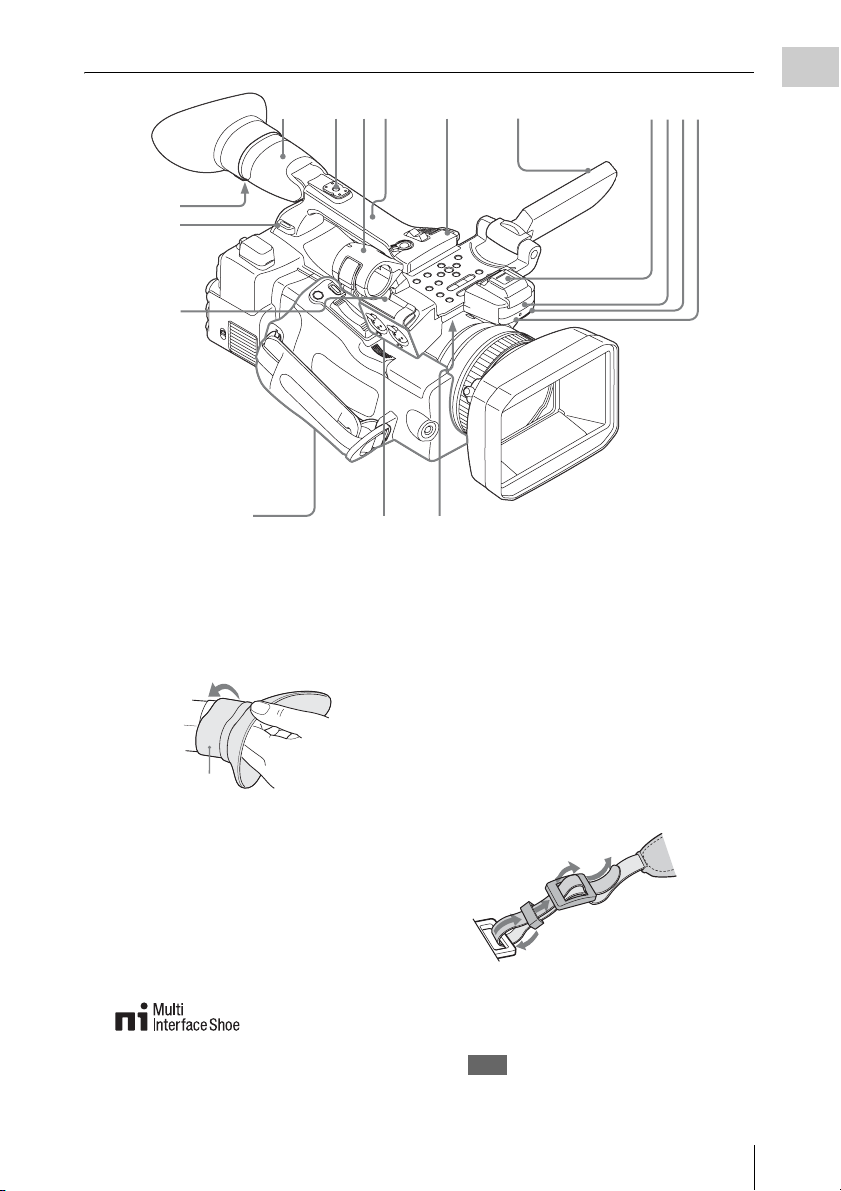
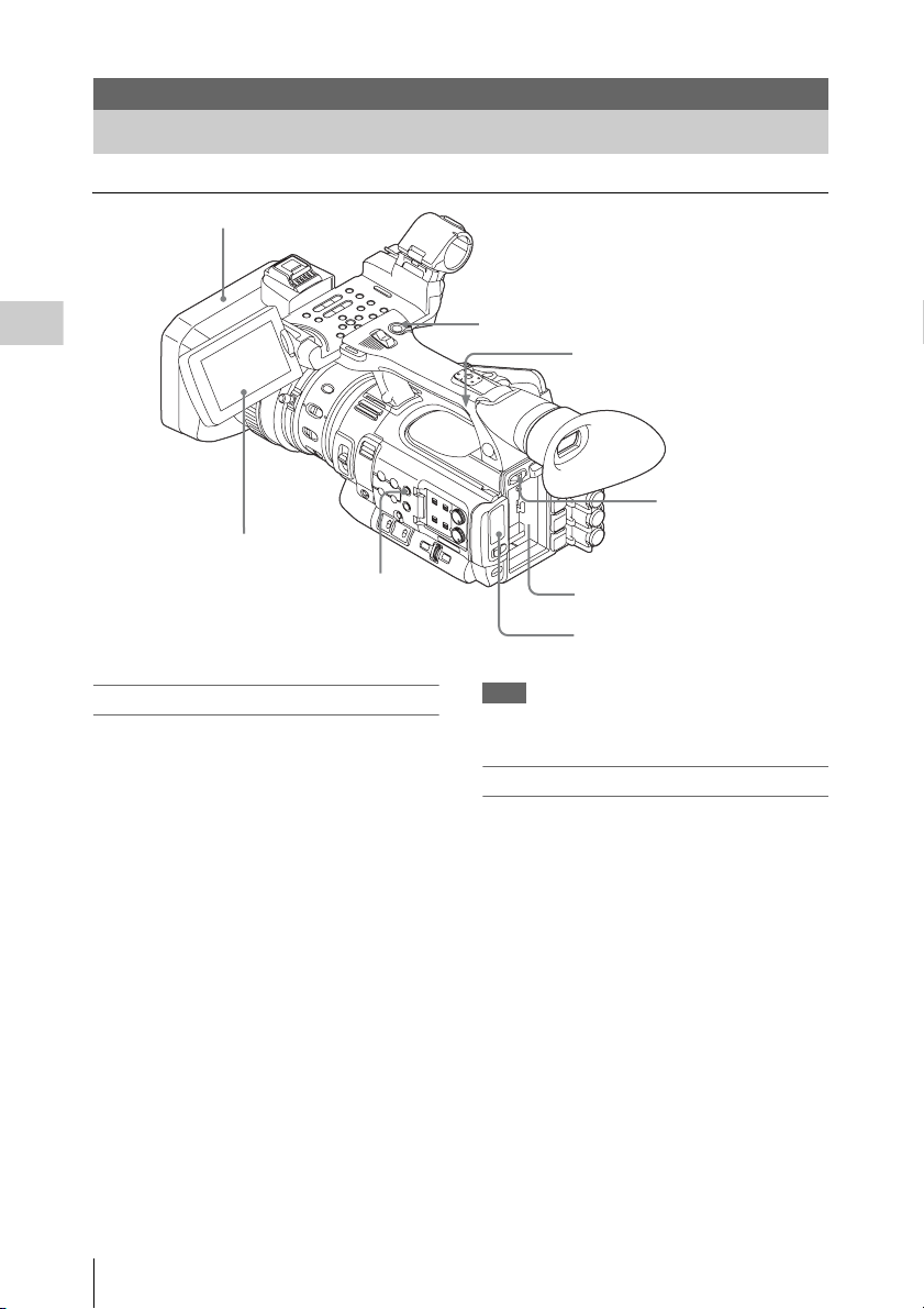
Camcorder
Operation panel on the
handle (page 10)
1
9
Lens control
block (page 11)
8
Side operation panel
(page 11)
1. Lens hood
Attach
Insert the hood by aligning the mark on the
camcorder and hood then turn the hood
clockwise (in the opposite direction of arrow 2
in the illustration below), with the front of the
camcorder facing forward, until the hood is
locked.
Detach
1 Press the PUSH (le ns food removing) button,
2 turn the hood in t he direction of the arrow, 3
then withdraw it.
4 5
2
3
Rear connector
panel (page 12)
6
7
Card slot block (page 12)
2. Headphone connector (stereo mini jack)
(page 38)
3. Rear remote sensor
4. Power switch (page 19)
5. BATT RELEASE button (page 18)
6. DC IN connector (page 19)
7. Battery pack receptacle (page 18)
8. WHITE BAL (automatic white balance
adjustment) button (page 32)
9. Lens cap open/close lever (page 28)
PUSH (lens hood
removing) button
Part Identification
8
Page 9
13
12
11
2
1
356
14
12
4
78
Overview
Controls on the grip
(page 13)
1. Viewfinder (page 20)
How to attach the EVF large eyecup
Stretch the EVF large eyecup for attaching to
the viewfinder and insert it aligning with the
horizontal groove of the eyecup.
EVF large eyecup
(supplied)
2. Rear accessory shoe (page 10)
3. External microphone holder (page 37)
4. LCD (Liquid Crystal Display) monitor
(page 20)
5. Front accessory shoe
The cover is attached. You can mount an
accessory compatible with the Multi
Interface Shoe.
For details about the compatible accessories
with the Multi Interface Shoe, contact your
dealer.
10
9
6. Built-in stereo microphone (page 37)
7. REC/TALLY lamp
8. Front IR remote control receptor
9. Built-in speaker (page 91)
10. AUDIO IN CH-1/CH-2 connectors (XLR)
and input selection (LINE/MIC/
MIC+48V) switches (page 37)
11. Microphone cable holder (page 37)
12. Hooks for the shoulder strap
Attach the supplied shoulder strap as shown
below.
4
3
2
1
13. Eyepiece focusing knob (page 21)
14. GPS module
This part contains the GPS module.
Note
Holding this part while using GPS functions may
affect the positioning accuracy.
Part Identification
9
Page 10
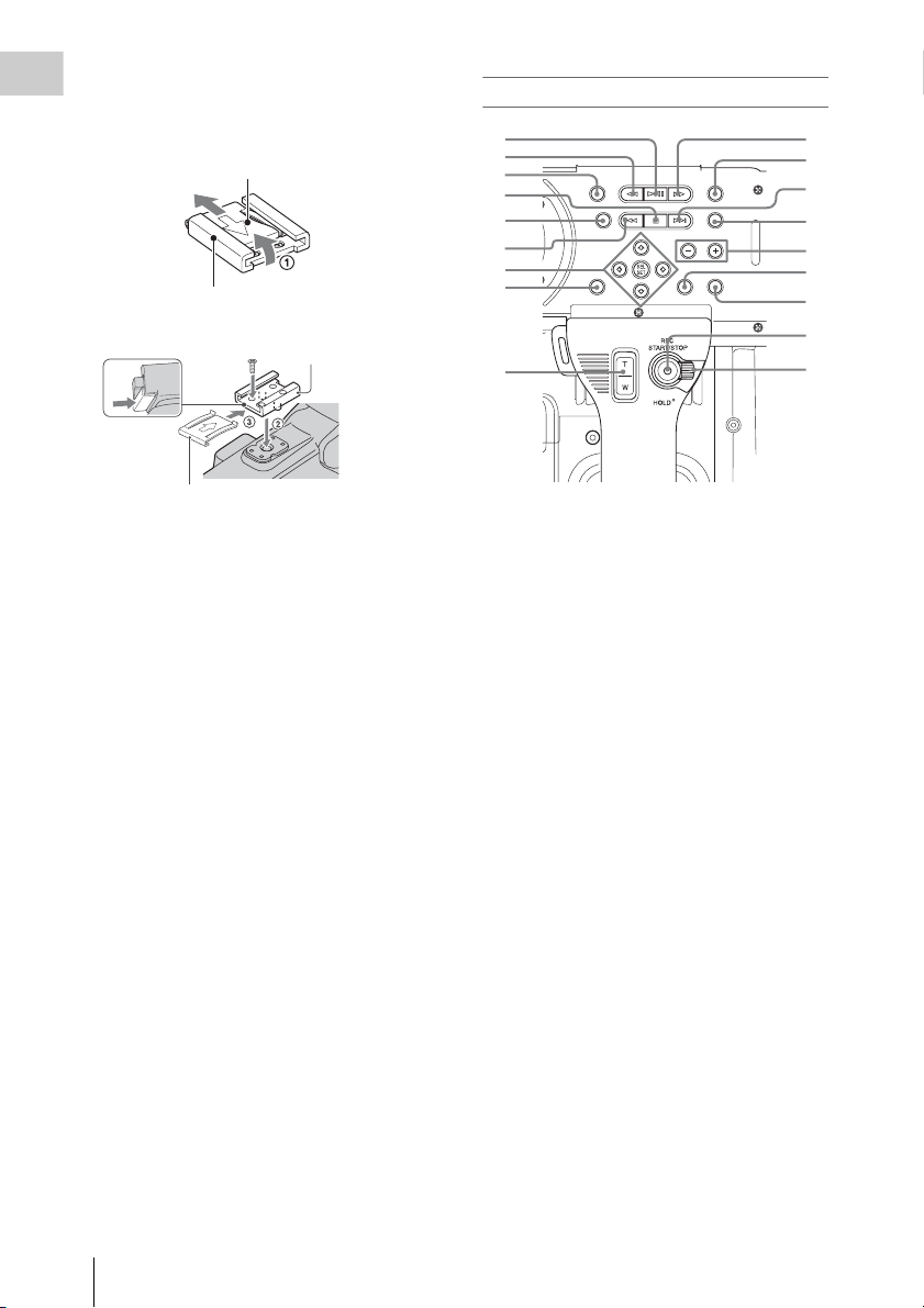
To mount the accessory shoe
Mount the accessory shoe on the accessory shoe
Overview
mount as illustrated.
Accessory shoe plate
Accessory shoe
Accessory shoe
Operation panel on the handle
1
2
3
4
5
6
7
8
9
10
11
12
13
14
15
16
17
18
Accessory shoe plate
1. Lift the edge of the accessory shoe plate and
pull it in the direction opposite to that of the
arrow on the accessory shoe plate and
remove it from the accessory shoe.
2. Place the accessory shoe so its protrusions
match recesses of the accessory shoe mount,
then fix it to the mount with four screws.
3. Insert the accessory shoe plate in the
direction of the arrow on the plate surface
until the end of the plate engages the end of
the shoe.
To remove the accessory shoe
Remove the shoe plate in the same way as step 1
of “To mount the accessory shoe.” Loosen the 4
screws and remove the accessory shoe from the
accessory shoe mount.
1. PLAY/PAUSE button (page 90)
2. F REV (fast reverse) button (page 91)
3. THUMBNAIL button (page 88)
4. STOP/CAM button (page 88)
5. STATUS (status display on/off) button
(page 98)
6. PREV (previous) button
7. Up/down/left/right buttons, SEL/SET
(select/set) button (page 103)
8. MENU (menu display on/off) button (page
103)
9. On-handle ZOOM button (page 34)
10. F FWD (fast forward) button (page 91)
11. LCD BRIGHT (LCD brightness
adjustment) button (page 20)
12. NEXT (clip directional jump) button
(page 91)
13. DISPLAY button (page 14)
14. VOLUME (monitor volume) buttons
(page 38)
15. CANCEL button
16. DURATION/TC/U-BIT (time data
selection) button (page 36)
17. REC START/STOP button (page 29)
18. REC HOLD lever (page 29)
Part Identification
10
Page 11
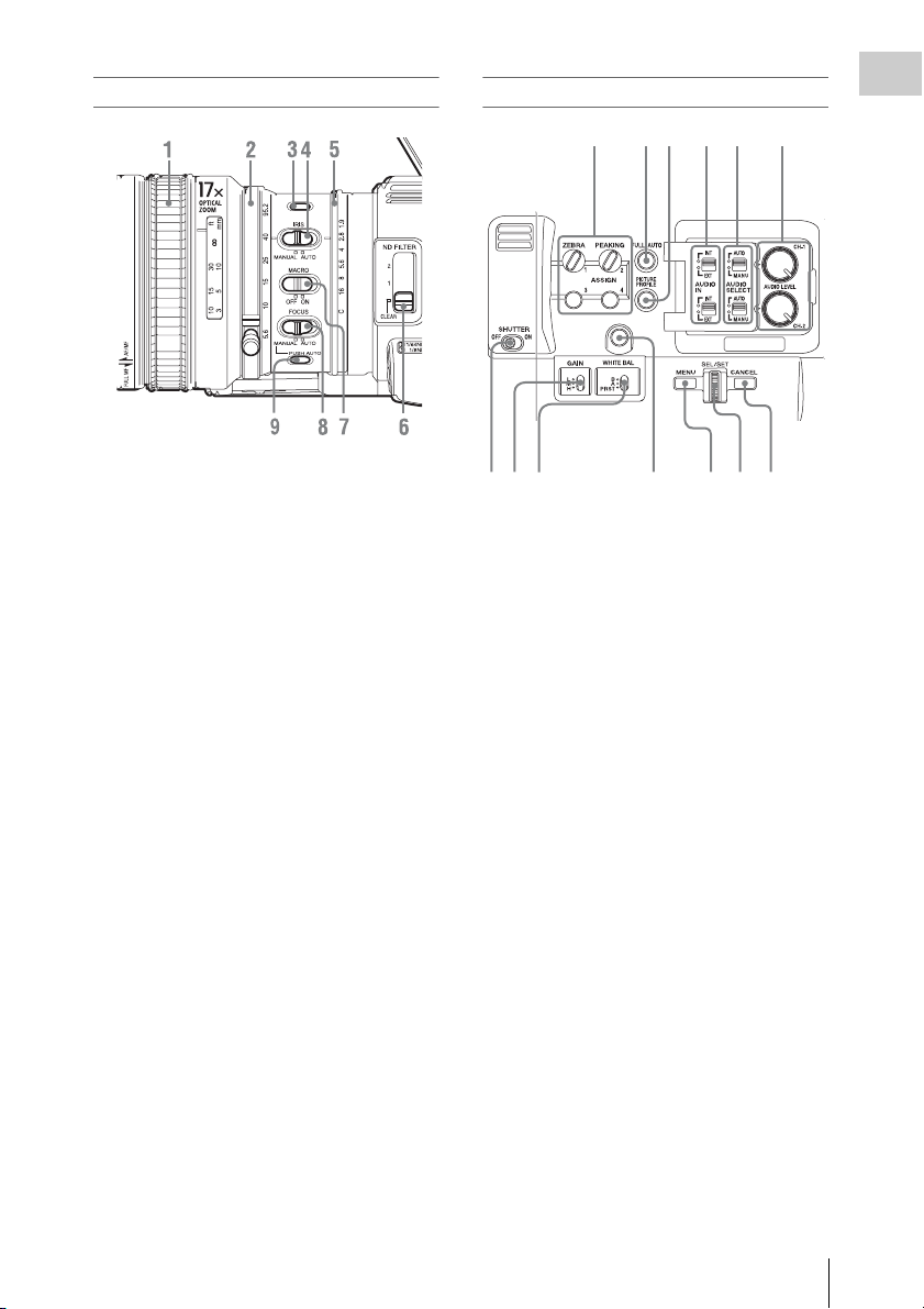
Lens control block
1. Focus ring (page 35)
2. Zoom ring (page 34)
3. STEADY SHOT button (page 36)
4. IRIS switch (page 34)
5. Iris ring (page 34)
6. ND FILTER select switch (page 31)
7. MACRO switch (page 36)
8. FOCUS switch (page 35)
9. PUSH AUTO (momentary auto focus)
button (page 35)
Side operation panel
1234
987
10
56
11 12 13
1. ASSIGN (assignable) 1/2/3/4 buttons (page
40)
“Zebra” is set to ASSIGN 1 and “Peaking” is
set to ASSIGN 2 by default.
2. FULL AUTO button and indicator (page
28)
3. PICTURE PROFILE button (page 46)
4. AUDIO IN (audio input selection)
switches (page 37)
5. AUDIO SELECT (audio level control
mode selection) switches (page 38)
6. AUDIO LEVEL CH-1/CH-2 knobs (page
38)
7. SHUTTER switch (page 33)
8. GAIN switch (page 33)
9. WHITE BAL (white balance memory)
switch (page 31)
10. ASSIGN (assignable) 5 button (page 40)
11. MENU (menu display on/off) button (page
103)
12. SEL/SET dial (jog dial) (page 103)
It functions accordingly when you turn it up or
down, or you push it horizontally.
It is called the “jog dial” in the subsequent
operating instructions.
13. CANCEL button
Overview
Part Identification
11
Page 12
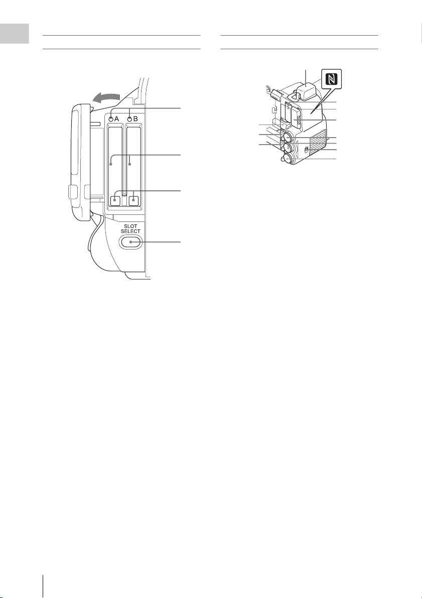
Card slot block
Overview
The SxS memory card slots and EJECT buttons
are located behind the cover.
Open the cover
Rear connector panel
1
5
1
2
3
4
1. ACCESS lamps (page 23)
2. SxS memory card slots (page 23)
3. EJECT (SxS memory card eject) buttons
(page 23)
4. SLOT SELECT (SxS memory card select)
button (page 23)
6
7
2
3
4
8
9
10
11
12
1. External device connector (page 26, 63)
2. PC connector (page 139)
3. i.LINK (HDV/DV) connector (4-pin, S400
conforming to IEEE1394) (page 139)
4. A/V OUT (audio/video multi output)
connector (page 139)
5. N mark
• Hold a NFC-compatible smartphone near
this mark when making wireless
connection between the camcorder and
smartphone. For details, refer to the
operating instructions of the smartphone.
• NFC (Near Field Communication) is the
international standard for the short range
radio communication technique.
6. HDMI OUT connector (page 138)
7. SD card ACCESS lamp
Lights in red while accessing the loaded SD
card.
8. SD card slot for proxy recording (page 60)
9. SDI OUT (serial digital output) connector
(BNC type) (page 138)
10. TC IN (timecode input)/TC OUT
(timecode output) connector (BNC type)
(page 144)
11. IN/OUT (input/output change) switch
(page 145)
Set this to IN to select TC IN and GENLOCK
IN, and set this to OUT to select TC OUT and
VIDEO OUT.
12. GENLOCK IN/VIDEO OUT (analog
video output) connector (BNC type) (page
138, 144)
Part Identification
12
Page 13
Controls on the grip
5
1. REC REVIEW button (page 29)
2. Power zoom lever (page 34)
3. FOCUS MAG button (page 35)
4. LENS REMOTE (lens remote controller)
connector (page 35)
5. REC START (start/stop recording)
button (page 29)
Bottom
1
23
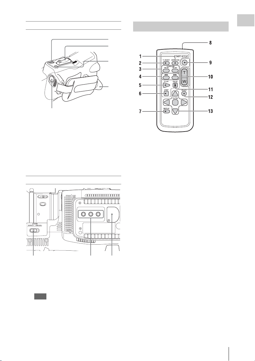
IR Remote Commander (Supplied)
Overview
1
2
3
4
1. DATA CODE button
This button does not work on the camcorder.
2. TC RESET (timecode reset) button
3. SCAN/SLOW (reverse high speed
playback/high speed playback) buttons
4. . > (PREV/NEXT(clip reverse/
forward direction jump)) buttons
5. PLAY button
6. STOP button
7. DISPLAY button
8. Transmitter
9. START/STOP (recording start/stop)
button
10. Power zoom lever
11. PAUSE button
12. MODE button
This button does not work on the camcorder.
13. b/B/v/V/ENTER buttons
1. ZOOM (zoom mode switching) switch
(page 34)
2. Tripod receptacles
Note
Check that the size of the hole matches the screw of
the tripod. If they do not match, the camcorder
cannot be attached to the tripod securely, and this
may lead to the physical injury of the camera
operator.
3. Backup battery holder (page 166)
Part Identification
13
Page 14
Overview
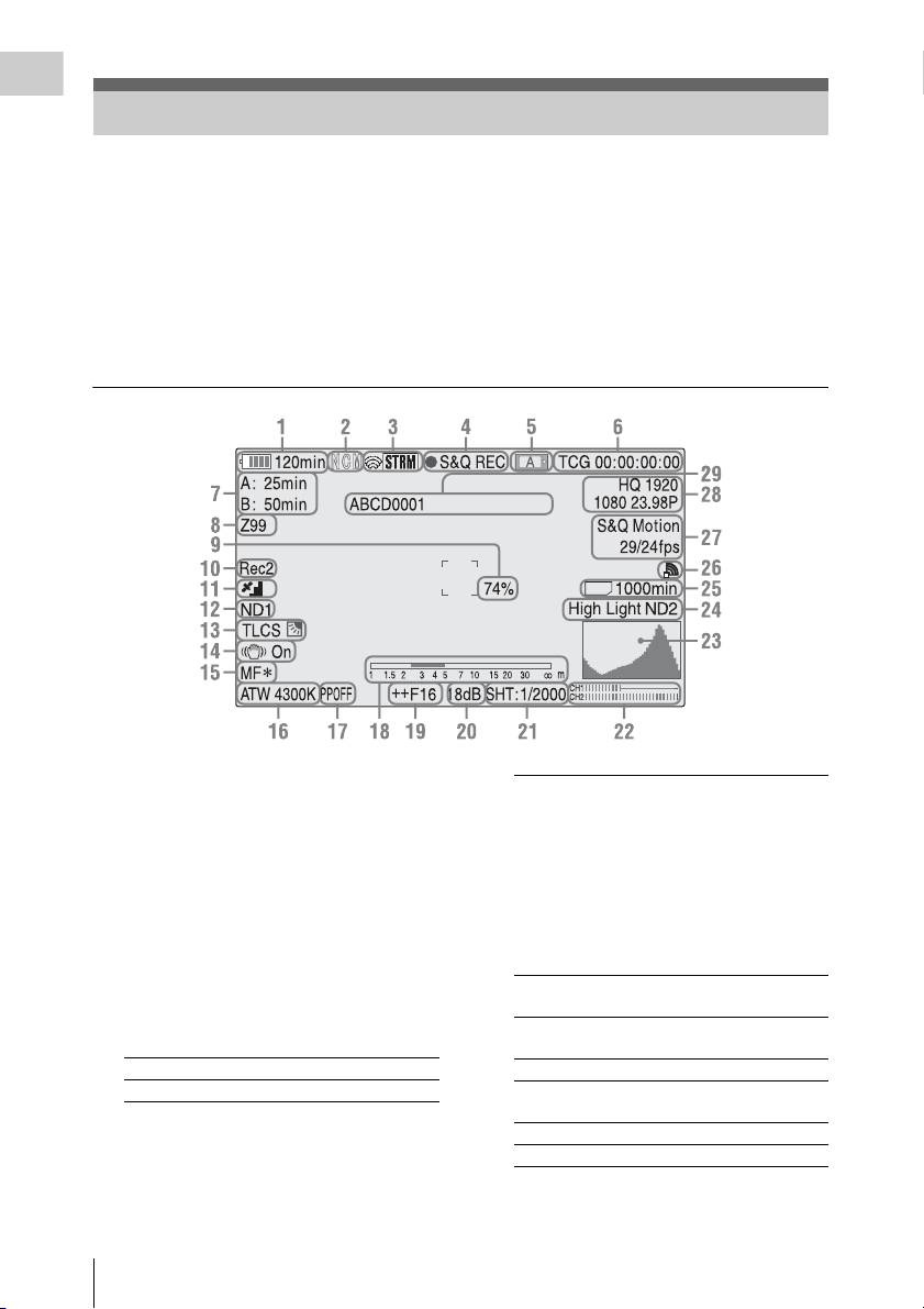
On-Screen Indications
While recording (or standing by to record), pressing the DISPLAY button displays the statuses and
settings of this unit on the LCD monitor/viewfinder screen.
Remarks
[M]: The indication of the items named with this suffix can be independently turned on/off with “Display
On/Off” of the LCD/VF SET menu (page 120).
[A]: The indication of items named with this suffix can be turned on/off using the assignable buttons to
which the corresponding on/off functions have been assigned (page 40).
[D]: The settings of the items named with this suffix can be changed using the Direct menu on the screen
(page 16).
SD
1. Battery remaining/DC IN voltage
indication [M] (page 18)
2. Network client mode status indication
The status of the connection in network client
mode is displayed (page 76).
3. i.LINK status indication/Streaming status
indication
The status of the connected equipment (page
141) or the streaming status is displayed (page
75).
4. Special recording/operation status
indication
zREC Recording in progress
STBY Standby for recording
On-Screen Indications
14
CONT Standby for Clip Continuous
Recording
“CONT” lit: Indicates that a
clip is being continued when
using Clip Continuous
Recording.
“CONT” flashing: Indicates
that there is no continuing clip
when using Clip Continuous
Recording.
zS&Q REC Slow & Quick Motion
recording in progress
S&Q STBY Standby for Slow & Quick
Motion recording
zINT REC Interval Recording in progress
INT STBY Standby for Interval
Recording
zFRM REC Frame Recording in progress
FRM STBY Standby for Frame Recording
Page 15
zCACHE z in green: Standby for
Picture Cache Recording
z in red: Picture Cache
Recording in progress
zSML REC Simultaneous Recording in
the 2 slots in progress
SML STBY Standby for Simultaneous
Recording of the 2 slots
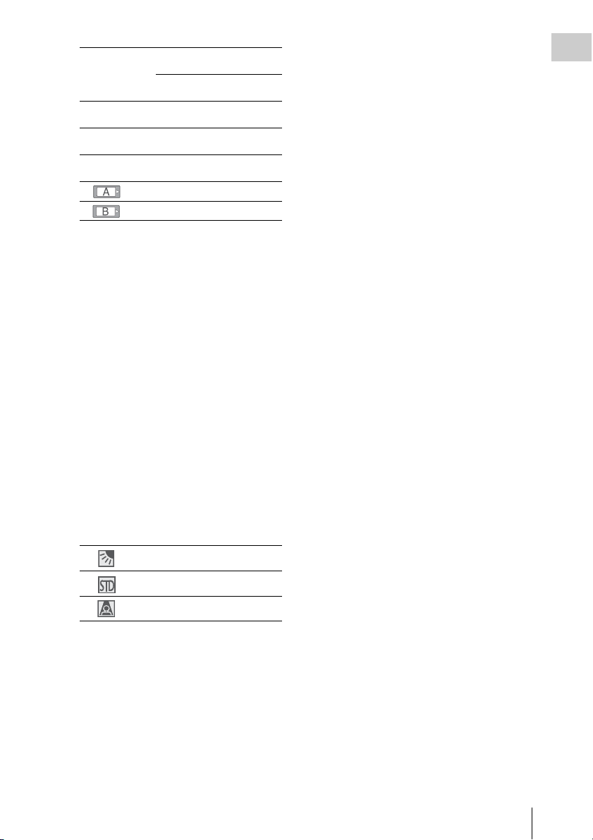
5. Media status indication
Memory card in slot A is active.
Memory card in slot B is active.
6. Time data indication [M] (page 36)
7. Media remaining indication [M] (page 24)
8. Zoom position indication [M] (page 34)
9. Brightness level indication [M][A]
10. Synchronous recording indication [M]
(page 138)
“Rec2” appears when recording while “SDI
Rec Control” of the VIDEO SET menu is set
to “HD SDI Remote I/F.”
“Rec2-P” appears when recording
synchronously while “Proxy” of the
CAMERA SET menu is set to “On.”
11. GPS status indication
The GPS positioning status are displayed as
icons.
“Obtaining Location Information (GPS)” (page 58)
12. ND FILTER position [M]
Displays the selected ND filter number (page
31).
13. TLCS mode indication [M][D] (page 113)
21. Shutter mode/shutter speed indication
[M][D] (page 33)
22. Audio level meters [M]
23. Histogram indication [M][A]
24. Video level cautioning indication [M]
/Recommended ND filter number
indication/Clip uploading status
indication
The clip uploading s tatus indication is displayed
when connected via wireless LAN. The number
of remaining clips for uploading and uploading
rate are displayed.
25. SD card remaining space indication
The remaining space of the SD card is displayed
while the SD card is inserted in the card slot of
the camcorder (page 60).
Overview
Backlight mode
Standard mode
Spotlight mode
14. Steady Shot indication [M] (page 36)
15. Focus mode indication [M] ([D] only in MF
mode) (page 35)
16. White balance mode and color
temperature indications [M][D] (page 31)
17. Picture profile indication [M][D] (page 46)
18. Depth-of-Field bar indication [M][A]
19. Iris position indication [M][D] (page 34)
20. Gain indication [M][D] (page 33)
On-Screen Indications
15
Page 16
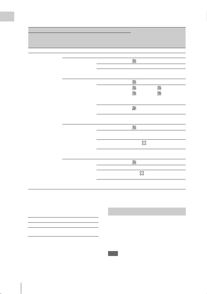
26. Network connection status indication
Overview
The network connection status is displayed as icons.
Conditions Icon
NETWORK SET
menu>”NW&
Proxy”/”USB”
“Off” or “USB A” – –
“Network&Proxy” “Off” –
NETWORK SET
menu>”Network
Mode
“Access Point” Preparing Wi-Fi
“Station” Preparing Wi-Fi
Modem Preparing 3G/4G
Network
connection status
Flashing
Connected to Wi-Fi AP
Wi-Fi cannot be
connected
Connected to Wi-Fi
Disconnected from WiFi
Wi-Fi cannot be
connected
Connected to 3G/4G 3G/4G
1)
Flashing
Intensity 1 Intensity 2
Intensity 3 Intensity 4
The icon changes depending on the
radio wave intensity.
No radio wave
1)
Flashing
Wired LAN Preparing LAN
1)
When the USB wireless LAN module is not connected, or the SSID is not set.
2)When the 3G/4G/LTE modem (optional) is not connected
3)When the USB-RJ45 adaptor (optional) is not connected
27. Special recording mode indication [M] ([D]
only in Slow & Quick Motion Standby)
Frame Rec Frame Rec mode
Interval Rec Interval Rec mode
S&Q Motion
xx/xx fps
Slow & Quick Motion mode
28. Video format indication [M] (page 30)
29. Clip name indication [M] (page 29)
On-Screen Indications
16
Disconnected from 3G/
4G
3G/4G cannot be
connected
Connected to LAN LAN
Disconnected from
LAN
LAN cannot be
connected
2)
3)
3G/4G
Flashing
LAN
Direct Menu Operation
The settings of the items named with a suffix [D]
can be changed using the Direct menu on the
screen.
Select “All,” “Part,” or “Off” for Direct Menu
using “Direct Menu” (page 137) of the OTHERS
menu.
Note
When the indicator of the FULL AUTO button is lit, the
Direct Menu operation is disabled for the functions that
are forcibly set to the automatic mode in Full Auto mode
(page 28).
Page 17

1 When the camcorder’s status or settings
are displayed on the screen, press the
SEL/SET button (page 10) or the jog
dial (page 11).
If “Direct Menu” is set to “All” or “Part,” the
cursor is displayed on one of the items for
which the Direct menu operation is
permitted.
2 Press the up/down/left/right buttons
(page 10) or rotate the jog dial to set the
cursor to the item to be operated, then
press the SEL/SET button or the jog
dial.
The Direct menu of the selected items appears.
3 Press the up/down/left/right buttons or
rotate the jog dial to select a setting,
then press the SEL/SET button or the
jog dial.
The menu disappears, and the new setting is
displayed.
Overview
On-Screen Indications
17
Page 18
Preparations
Power Supply
You can use a battery pack or AC power via an
AC adaptor.
Preparations
For safety, use only the Sony battery packs and
AC adaptors listed below.
Lithium-ion Battery Pack
BP-U30
BP-U60
BP-U60T
BP-U90
Battery Charger/AC Adaptor
BC-U1
BC-U2
The life expectancy of the AC adapter and the
electrolytic capacitor is about 5 years under
normal operating temperatures and normal usage
(8 hours per day; 25 days per month). If usage
exceeds the above normal usage frequency, the
life expectancy may be reduced correspondingly.
The battery terminal of this unit (the connector for
battery packs and AC adaptors) is a consumable
part.
Power may not be supplied to the unit properly if
the pins of the battery terminal are bent or
deformed by shock or vibrations, or if they
become corroded due to prolonged outdoor use.
Periodic inspections are recommended to keep
the unit working properly and to prolong its
usable lifetime.
Contact a Sony service or sales representative for
more information about inspections.
WARNING
Batteries shall not be exposed to excessive heat
such as sunshine, fire or the like.
Note
The AC adaptor cannot be connected to the camcorder
while the battery pack is inserted.
Using a Battery Pack
Fully insert the battery pack into the battery pack
receptacle (page 8), then slide it down to lock it.
To remove the battery pack, press and hold the
BATT RELEASE button (page 8), slide the
battery pack upward to unlock it, then pull it out.
Notes
• Before use, charge the battery pack with the supplied
BC-U1 or BC-U2 Battery Charger.
• A warm battery pack immediately after use m ay not be
able to be fully recharged.
• The high-capacity BP-U90 Battery Pack is large, and
protrudes from the camcorder when attached. When
using the camcorder with the BP-U90 attached for
extended recording periods, Sony recommends
attaching the camcorder to a tripod for convenience.
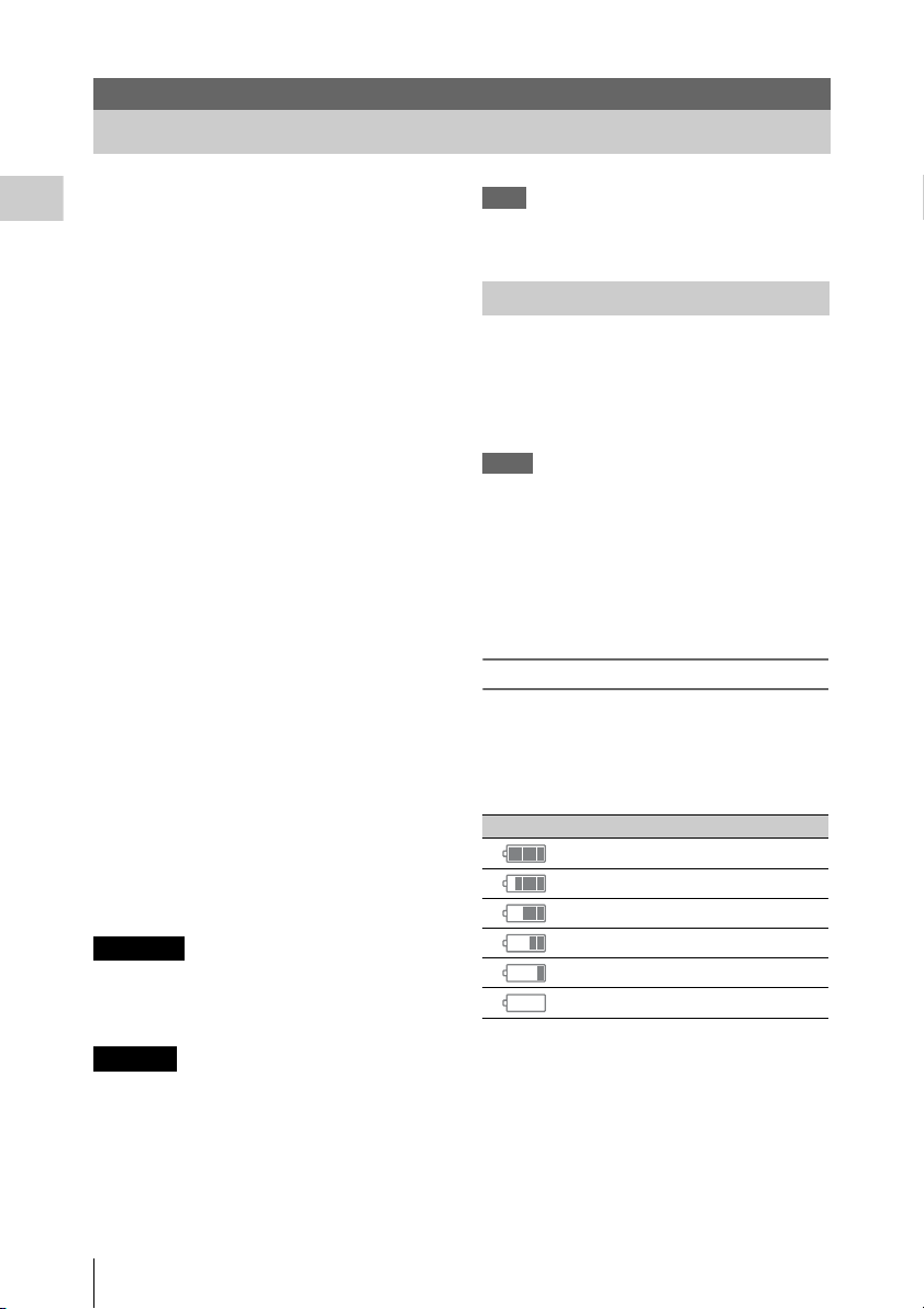
Checking battery charge remaining
When recording or playback is in progress on the
battery pack, an icon to show the current battery
charge level and usage time remaining are
displayed on the LCD monitor/viewfinder screen
(page 14).
Icon Remaining
100% to 91%
90% to 71%
70% to 51%
50% to 31%
30% to 11%
10% to 0%
CAUTION
Danger of explosion if battery is incorrectly
replaced. Replace only with the same or
equivalent type recommended by the
manufacturer.
When you dispose of the battery, you must obey
the law in the relative area or country.
Power Supply
18
The camcorder indicates the remaining usage
time in minutes by calculating the available time
with the battery pack if operation is continued at
the current rate of power consumption.
Page 19
If the battery charge remaining becomes
low
If the battery charge remaining decreases to a
certain level during operation (Low BATT
status), a low-battery message, flashing of the
tally lamps, and a beep sound will warn you.
If the remaining further decreases to a level at
which operation cannot be continued (BATT
Empty status), a battery-empty message appears.
Replace the battery pack with one that is fully
charged.
To change the message levels
The Low BATT level is set to 10% of full charge,
and the BATT Empty level is set to 3% of full
charge at the factory. These settings can be
changed with “Battery Alarm” (page 132) of the
OTHERS menu.
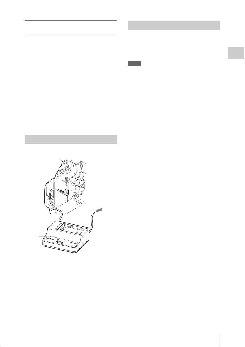
Using AC Power (DC IN Power)
Connection example: when connecting BC-U1
Turning the Power On/Off
To turn the power on, set the power switch (page
8) to the ON position (the ? position). To turn the
power off, set the power switch to the OFF
position (the 1 position).
Notes
• This camcorder uses a little standby power even when
the power switch is set to OFF. Remove the battery
pack if the camcorder will not be used for a prolonged
period.
• When removing the battery pack or the DC IN power,
be sure to first set the power switch to the OFF
position. Removing the battery pack or the DC IN
power while the camcorder is on may cause damage to
the camcorder or the SxS memory card.
Preparations
1
2
3
DC OUT
CHARGE
0%
80
BATTERY CHARGER
BC-U1
100
BC-U1
1 Connect the DC power output cable of
the BC-U1 to the DC IN connector of
the camcorder.
2 Connect the p ower cord of the BC-U1 to
an AC power source.
3 Set the mode switch of the BC-U1 to the
DC OUT position.
Power Supply
19
Page 20

Setting the Clock Adjusting the LCD
When you turn the camcorder on for the first time
after purchasing or replacing the backup battery
(page 166), the Initial Setting display appears on
Preparations
the LCD monitor/viewfinder screen.
Set the date and time of the built-in clock, using
this display.
Time Zone
The value shows the time difference from UTC
(Coordinated Universal Time).
Change the setting if needed.
Setting the time and date
Press the up/down/left/right buttons (page 10) or
turn the jog dial (page 11) to move the cursor,
then press the SEL/SET button or the jog dial to
set each menu item. When you press the SEL/
SET button or the jog dial when the cursor is on
“Finish,” the Initial Setting display disappears
and the clock setting is completed.
After the Initial Setting display disappears, “Time
Zone” (page 130) and “Clock Set” (page 130) of
the OTHERS menu can be used to set “Time
Zone” and “Date/Time.”
Notes
• If the clock setting is cleared because of exhaustion of
the backup battery while no operation power was being
supplied (no battery pack and no DC IN connection),
the Initial Setting display will be displayed when you
turn the camcorder on at the next opportunity.
• While the Initial Setting display is shown, no other
operation except turning the power off is permitted
until you finish the setting for this display.
Monitor and Viewfinder
Adjusting the LCD Monitor
The LCD monitor turns on when it is opened and
turns off when it is returned to the park position.
Adjusting the angle
It can be rotated as much as 90 degrees in the
direction facing the subject and as much as 180
degrees in the opposite direction.
When you rotate it 90 degrees toward the subject,
the image on the monitor becomes upside down,
indicating the mirror image of the subject. The
display direction of the textual information is
converted to the readable direction.
Adjusting the backlight
Press the LCD BRIGHT button (page 10) to
adjust the brightness of the backlight.
Adjusting the color, contrast, and
brightness
These adjustments can be made using “LCD”
(page 119) of the LCD/VF SET menu. These
adjustments of the LC D monitor have no effect on
pictures being recorded.
Adjusting the Viewfinder
If the picture on the LCD monitor is hard to view
under bright ambient light, you can use the
viewfinder to check the picture.
Setting the Clock / Adjusting the LCD Monitor and Viewfinder
20
Caution
Do not leave the camcorder with the eyepiece of
the viewfinder facing the sun. Direct sunlight can
enter through the eyepiece, be focused in the
viewfinder, and cause fire.
Hereafter the viewfinder is referred to as “EVF”
(abbreviation of Electronic Viewfinder).
Page 21
Turning the EVF on/off
With the factory setting, the EVF is turned on
when the LCD monitor is in its park position or is
rotated to face the subject.
You can change the setting so that the EVF is
always on regardless of the status in the LCD
monitor, using “EVF” (page 119) of the LCD/VF
SET menu. Change the “Power” setting from
“Auto” to “On.”
Adjusting the focus in the EVF
The eyepiece focusing (diopter compensation)
knob (page 9) enables adjustment to match the
eyesight of the operator, who can then view the
image clearly through the eyepiece.
Adjusting the backlight
The brightness of the backlight for the EVF can
be switched between High and Low.
Set “Backlight” in “EVF” (page 119) of the LCD/
VF SET menu.
Switching between color and
monochrome modes
For the EVF screen, color or monochrome display
can be selected.
Set “Mode” in “EVF” (page 119) of the LCD/VF
SET menu.
Select “B&W” if checking the subject and
focusing are easier on the monochrome display.
If you assign “EVF Mode” to one of the
assignable buttons (page 40), you can switch
between color and monochrome by pressing the
button.
Adjusting the contrast and brightness
Use “EVF” (page 119) of the LCD/VF SET menu
to make adjustments. Adjusting the brightness
and other items has no effect on pictures being
recorded.
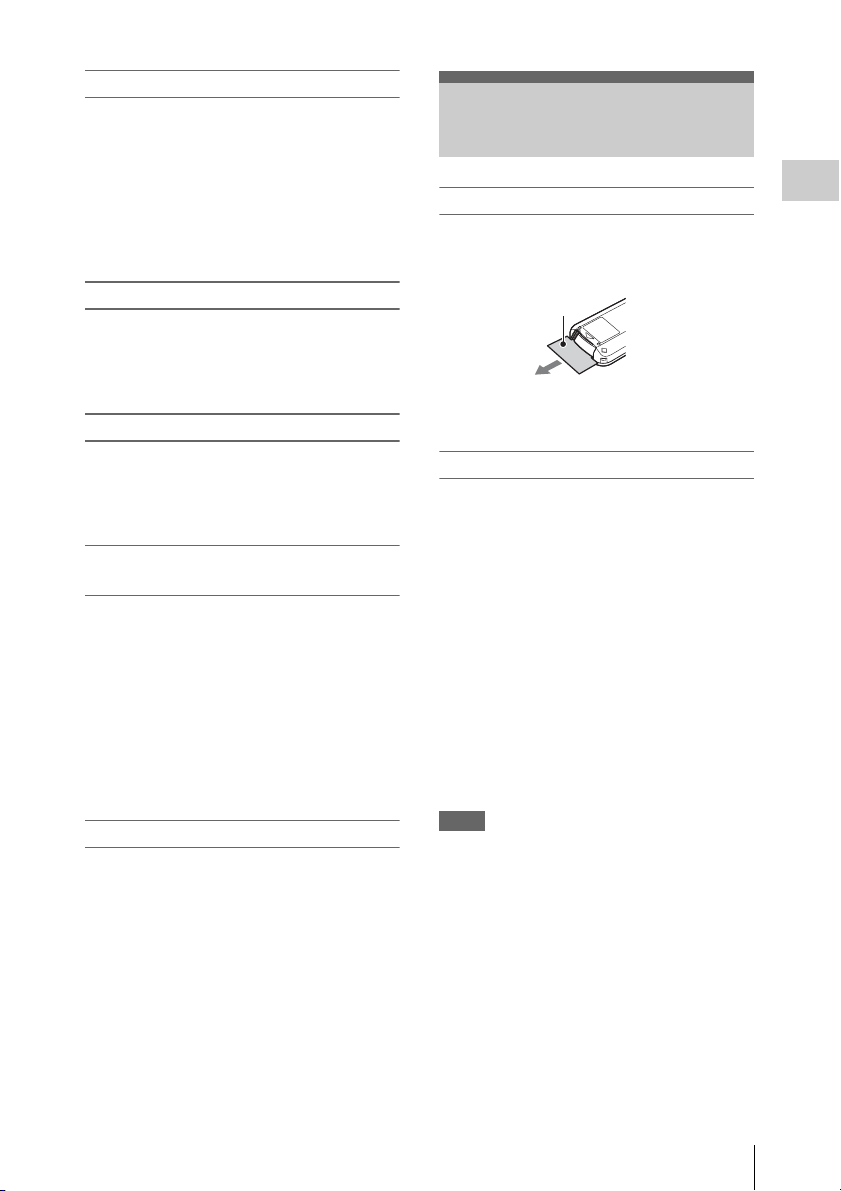
Using the IR Remote Commander
Before use
Before you use the supplied IR Remote
Commander for the first time, pull out the
insulation sheet from the battery holder.
Insulation sheet
A CR2025 lithium battery is set in the holder at
the factory.
Using the IR Remote Commander
For controlling the camcorder from the IR
Remote Commander, activate the remote control
function of the camcorder after turning the power
on.
Activating/deactivating the remote control
function can be achieved using the Setup menu.
To activate using the menu
Press the MENU button to set the camcorder to
Menu mode, then set “IR Remote” (page 132) of
the System menu to “On.”
To activate using the assignable button
If you assign “IR Remote” to one of the
assignable buttons (page 40), you can switch
between activating and deactivating the remote
control function by pressing the button.
Notes
• Aim the IR Remote Commander towards the remote
sensor to operate your camcorder.
• Point the remote sensor away from strong light sources
such as direct sunlight or overhead light ing. Otherwise,
the IR Remote Commander may not function properly.
• When you are operating with the IR Remote
Commander supplied with your camcorder, your video
device may also operate. In that case, select a
commander mode other than DVD2 for your video
device, or cover the sensor of your video device with
black paper.
• The remote control function is deactivated
automatically when the camcorder is turned off to
prevent a malfunction. To use the remote control
function, activate it when the camcorder is turned on.
Preparations
Using the IR Remote Commander
21
Page 22

Replacing the battery in the IR Remote
Commander
Use a commercially available CR2025 lithium
battery. Do not use any battery other than a
CR2025.
Preparations
1. While pressing on the tab, inset your
fingernail into the slit to pull out the battery
case.
2. Place a new battery with the + side facing up.
3. Insert the battery case back into the IR
Remote Commander until it clicks.
Tab
WARNING
• Battery may explode if mistreated.
Do not recharge, disassemble, or dispose of in
fire.
• Batteries shall not be exposed to excessive heat
such as sunshine, fire or the like.
CAUTION
Danger of explosion if battery is incorrectly
replaced. Replace only with the same or
equivalent type recommended by the
manufacturer.
When you dispose of the battery, you must obey
the law in the relative area or country.
Using SxS Memory Cards
This camcorder records audio and video on SxS
memory cards (optional) inserted in the card slots.
About SxS Memory Cards
Usable SxS memory cards
Use the following Sony-made SxS memory cards.
Operations are not guaranteed with memory ca rds
other than the following cards.
SxS PRO+ series
SxS PRO series
SxS-1 series
These cards comply with the ExpressCard
standard.
For details on using SxS memory cards and usagerelated precautions, refer to the instruction manual
for the SxS memory card.
SxS, SxS PRO and SxS-1 are trademarks of Sony
Corporation.
The ExpressCard word mark and logo are owned
by Personal Computer Memory Card
International Association (PCMCIA) and are
licensed to Sony Corporation. All other
trademarks are the property of their respective
owners.
Note
The Slow & Quick Motion recording (page 43) with
XAVC-I format may not be performed correctly
depending on the SxS-1 memory card used. An SxS PR O
or SxS PRO+ memory card is recommended.
Using SxS Memory Cards
22
Page 23

Inserting/Removing an SxS Memory Card
Switching Between SxS Memory Cards
Inserting an SxS memory card
1 Open the cover of the card slot block
(page 12).
2 Insert the SxS memory card into the slot
with the SxS label facing right.
The ACCESS lamp (page 12) lights in red
then changes to green once the memory card
is ready for use.
3 Close the cover.
Status indications by the ACCESS lamps
Card slots A and B are accompanied by the
respective ACCESS lamps to indicate their
statuses.
Lamp Slot statuses
Lights in
red
Lights in
green
Off • No SxS memory card is loaded.
Accessing the loaded SxS memory card
(writing/reading data)
Standby (ready for recording or
playback using the loaded SxS memory
card)
• The loaded card is invalid.
• An SxS memory card is loaded, but
another slot is active.
Removing an SxS memory card
1 Open the cover of the card slot block,
press the EJECT button (page 12), then
pull the button out.
2 Press the EJECT button again to
remove the card.
Note
Data are not guaranteed if the power is turned off or a
memory card is removed while the card is being
accessed. All data on the card may be destroyed. Be sure
that the ACCESS lamps are lit in green or off when you
turn off the power or remove memory cards.
When SxS memory cards are loaded in both card
slots A and B, press the SLOT SELECT button
(page 12) to select the card you wish to use.
If a card becomes fu ll during recording, switching
to the other card is automatically executed.
Note
The SLOT SELECT button is disabled while playback is
in progress. Switching is not executed even if you press
the button. The button is enabled while the thumbnail
screen is displayed (page 88).
Formatting an SxS Memory Card
For an SxS memory card that is not formatted or
that was formatted with another system, the
message “Unsupported File System” is displayed
on the LCD monitor/EVF screen.
Format the card as instructed in “To execute
formatting” below.
To execute formatting
Using “Format Media” (page 135) of the
OTHERS menu, specify “Media(A)” (slot
A) or “Media(B)” (slot B) then select
“Execute.” On a confirmation message,
select “Execute” again.
The in-progress message and status bar (%) are
displayed, and the ACCESS lamp lights in red.
When formatting is completed, the completion
message is displayed for three seconds.
Recording/playback during formatting
You can perform recording or playback using the
SxS memory card in the other card slot while
formatting is in progress.
If formatting fails
A write-protected SxS memory card or memory
card that cannot be used with this camcorder will
not be formatted.
As a warning message is displayed, replace the
card with an appropriate SxS memory card, as per
the instructions in the message.
Preparations
Using SxS Memory Cards
23
Page 24

Notes
• Use the format function of this camcorder to format
SxS memory cards for use on this camcorder. The
formats of cards formatted on other devices are not
recognized as valid formats, making it necessary to
format them again on this camcorder.
• All the data, including recorded pictures and setup
files, are erased when a memory card is formatted.
Preparations
Checking the Remaining Time Available for Recording
While recording (or standing by to record), you
can check the time remaining for the SxS memory
cards loaded in the card slots on the LCD
monitor/EVF screen (page 14).
The available time for recording with the current
video format (recording bit rate) is calculated
according to the remaining space of each card and
displayed in time units of minutes.
The remaining can also be checked in a meter
format on the Battery/Media status screen (page
99).
Notes
• A icon appears if the memory card is writeprotected.
• The displayed remaining time is only a guide.
The actual remaining time may be less than the one
displayed since the memory card has data other than
video such as the management area.
Replacing an SxS memory card
• If the available time on two cards in total
becomes less than 5 minutes, a message “Media
Near Full,” flashing of the tally lamps, and a
beep sound will warn you. Replace the cards
with those with sufficient space.
• If you continue recording until the total
remaining time reaches zero, the message
changes to “Media Full,” and recording stops.
Note
Approximately 600 clips can be recorded on one SxS
memory card at maximum.
If the number of recorded clips reaches the limit, the
remaining time indication becomes “0,” and the message
“Media Full” is displayed.
Restoring an SxS Memory Card
If an error occurs with data in a memory card for
some reason, the card must be restored.
If an SxS memory card that needs to be restored
is loaded, a message that prompts you to execute
a restore operation is displayed on the LCD
monitor/EVF screen.
To restore a card
Select “Execute” by pressing the up/down/
left/right buttons or turning the jog dial,
then push the SEL/SET button or the jog
dial.
During restoration, the in-progress message and
status bar (%) are displayed, and the ACCESS
lamp is lit in red.
When restoration is completed, the completion
message is displayed for three seconds.
If restoration fails
• A write-protected SxS memory card or one on
which an error occurred cannot be restored. For
such a card, a warning message is displayed.
Release the write protection or replace the card,
as per the instructions in the message.
• An SxS memory card on which an error
occurred may become usable again through
repeated formatting.
• In some cases, only parts of clips cannot be
restored. Playback of the restored clips becomes
possible again.
• The following operation may restore an SxS
memory card for which the message “Could not
Restore Some Clips” is repeatedly displayed
each time you try the restoration process:
1 Copy necessary clips to another SxS memory
card, using the copy function (page 94) of the
camcorder or the dedicated application
software (supplied) (page 140).
2 Format the problem SxS memory card, using
the format function of this camcorder.
3 Return the necessary clips to the SxS
memory card by copy operation.
Recording/playback during restoration
You can perform recording or playback using the
SxS memory card in the other card slot while
restoration is in progress.
Note
For restoration of media recorded with this unit, be sure
to use this unit. Media recorded with a device other than
this unit or with another unit of different version (even of
the same model) may not be restored using this unit.
Using SxS Memory Cards
24
Page 25

Using Other Media
Notes
• Medias other than an SxS memory card cannot obtain
the high reliability and durability equivalent to an SxS
memory card for professional use.
• Not all memory cards have been verified to function
with this camcorder. For compatible memory cards,
contact your dealer.
• When you use media with this camcorder, format the
media using the unit’s formatting function.
XQD Memory Cards
By using an optional QDA-EX1 Media Adaptor,
you can insert an XQD memory card into the SxS
memory card slot and use it instead of an SxS
memory card.
For details on using a QDA-EX1 Media Adaptor,
refer to the instruction manual supplied with it.
Notes
• High-speed playback (page 10) may not be properly
achieved with an XQD memory card.
• Recording with XAVC-I format or the Slow & Quick
Motion recording (page 43) may not be performed
correctly depending on the XQD memory card used.
An SxS PRO or SxS PRO+ memory card is
recommended.
Formatting
When you use an XQD memory card with this
camcorder, formatting is required.
An XQD memory card to be used with this
camcorder must be formatted using the format
function of this camcorder.
It is also necessary to format an XQD memory
card for use if a caution message is displayed
when you mount the XQD memory card.
For an XQD memory card that was formatted
with another system unsupported by this
camcorder, the message “Unsupported File
System” is displayed on the LCD monitor/EVF
screen.
Format the XQD memory card as instructed
below.
To execute formatting
Using “Format Media” (page 135) of the
OTHERS menu, specify “Media(A)” (slot
A) or “Media(B)” (slot B), then select
“Execute.”
An in-progress message and status bar (%) are
displayed, and the ACCESS lamp lights in red.
When formatting is completed, a completion
message is displayed for three seconds.
Note
When formatting, all data in an XQD memory card—
including protected images—are erased and cannot be
restored.
Connection between the camcorder and a PC
To use an XQD memory card in which data have
been recorded with an XDCAM/XDCAM EXseries product, insert it into the slot of the
camcorder and connect between the PC and this
camcorder using a USB cable.
To use media formatted with this camcorder in
the slots of other devices
Make a backup of the media, then format it using
the other device.
SD Cards
Use of the optional MEAD-SD02 Media Adaptor
permits you to insert an SD card into the SxS
memory card slot and use it for recording and
playback in the same way as with an SxS memory
card.
For details on use of the MEAD-SD02 Media
Adaptor, refer to the operating instructions supplied
with the respective adaptor.
Note
High-speed playback (page 10) may not be properly
achieved with an SD card.
SDHC card (FAT only)
Class 10 SDHC card
Note
SDHC cards cannot be used in UDF and exFAT.
SDXC card (exFAT only)
Class 10 SDXC card
Notes
• SDXC cards can only be used in exFAT.
• When you use an SDXC card, do not use other types of
memory cards simultaneously. If you use other types
of media simultaneously, switching to other media
cannot be executed when the media has no space while
recording.
Preparations
Using Other Media
25
Page 26

• Recording with XAVC-I format or the Slow & Quick
Motion recording (page 43) may not be performed
correctly depending on the SDXC card used. An SxS
PRO or SxS PRO+ memory card is recommended.
• An SDXC card recorded with the camcorder of the
PMW and PXW series may not be able to be used for
recording and playback with this unit depending on the
type of unit used. For details, contact your Sony dealer
or a Sony service representative.
Preparations
Formatting
When you use an SD card with this camcorder,
formatting is required.
An SD card to be used with this camcorder must
be formatted using the format function of this
camcorder.
It is also necessary to format an SD card for use if
a caution message is displayed when you mount
the SD card.
For an SD card that was formatted with another
system unsupported by this camcorder, the
message “Unsupported File System” is displayed
on the LCD monitor/EVF screen.
Format the SD card as instructed below.
To execute formatting
Using “Format Media” (page 135) of the
OTHERS menu, specify “Media(A)” (slot
A) or “Media(B)” (slot B), then select
“Execute.”
An in-progress message and status bar (%) are
displayed, and the ACCESS lamp lights in red.
When formatting is completed, a completion
message is displayed for three seconds.
Note
When formatting, all data in an SD card including
protected images are erased and cannot be restored.
Connection between the camcorder and a PC
To use an SD card in which data have been
recorded with an XDCAM/XDCAM EX-series
product, insert it into the slot of the camcorder
and connect between the PC and this camcorder
using a USB cable.
To use media formatted with this camcorder in
the slots of other devices
Make a backup of the media, then format it using
the other device.
USB Flash Drives
UDF
In UDF or exFAT, you can connect a USB flash
drive to the external device connector (page 12)
to record, save, and load the following data.
• “Loading a Planning Metadata file” (page 56)
• “Storing/Retrieving the Setting Data” (page
54)
Using Sony USB flash drives is recommended.
Notes
• Use USB flash drives with a capacity of 4 GB to
32 GB.
• USB flash drives other than those listed above may not
be recognized if connected to the external device
connector.
When using the external device connector
Set “NW&Proxy/USB” (page 124) of the
NETWORK SET menu to “USB A.”
Notes
• During this setting, “XAVC-L50 1920×1080/59.94P,
50P” and “XAVC-L35 1920×1080/59.94P, 50P”
cannot be selected for “Format” in “System” (page
133) of the OTHERS menu.
• During this setting, 60fps and 50fps cannot be selected
for “Frame Rate” in “S&Q Motion” when “Format” in
“System” of the OTHERS menu is set to “1920×1080/
29.97P, 23.98P, 25P.”
Formatting (Initializing) USB Flash
Drives
USB flash drives must be formatted with the
FAT32 file system.
Note
Before using a drive, format it on this camcorder or a PC.
If a drive formatted on a PC cannot be used, format it on
the camcorder.
1 Connect a USB flash drive to the
external device connector.
If the drive is unformatted or has been
formatted to other specifications, a message
to confirm whether formatting is to be
executed appears on the EVF screen.
2 Using the up/down/left/right buttons or
the jog dial, select “Execute,” then press
the SEL/SET button or the jog dial.
Using Other Media
26
Page 27

The in-progress message and status bar (%)
are displayed, and formatting is started.
When formatting is completed, the message
“Format USB Memory Done” is displayed.
The \MSSONY\PRO\XDCAM\MEMDISC
folder and the \G eneral\Sony\Planning folder
are automatically created in the drive.
If the format operation fails
A format operation may fail because the USB
flash drive is write protected, or because it is not
the type of drive specified for use with this
camcorder.
In this case, an error message appears. Follow the
instructions in the error message and exchange
the drive for one that can be used with this
camcorder.
Restoring USB Flash Drives
When you load a USB flash drive that cannot be
mounted normally because the file system is
destroyed, a message appears on the LCD
monitor/EVF screen to ask whether you want to
restore it.
Using the up/down/left/right buttons or the jog
dial, select “Execute,” then press the SEL/SET
button or the jog dial. The in-progress message
and status bar (%) are displayed, and restoration
is started.
When restoration is completed, the message
“Restore USB Memory Done” is displayed.
Preparations
• “XQD” is a trademark of Sony Corporation.
Using Other Media
27
Page 28
Recording
Basic Operation Procedure
Open the lens cap
4
Recording
3
LCD monitor
angle
adjustment
6
FULL AUTO
7, 8 REC START/STOP
9 REC REVIEW (on the grip)
5 Power switch:
ON (the " position)
1 Battery pack insertion
2 SxS memory card slots
Preparations
1 Mount a fully charged battery pack.
2 Load SxS memory card(s).
If you load two cards, recording is continued
by automatically switching to the second
card when the first card becomes full.
3 Adjust the angle of the LCD monitor for
the best view.
When you wish to use the EVF, fold the LCD
monitor to its park position and adjust the
angle of the EVF.
4 Open the lens cap.
Pull up the lens cap open/close lever to open
the lens cap built in the lens hood.
5 Set the power switch to the ON position.
The recording screen is displayed.
When using the remote commander, activate the
remote control mode (page 21).
Basic Operation Procedure
28
Note
When you hold the camcorder by the grip, support it
from underneath with your left hand.
Recording (Full Auto mode)
6 Press the FULL AUTO button so that
the button indicator lights.
Full Auto mode is turned on, TLCS (Total
Level Control System) (page 113) is
activated, Auto Iris, AGC (Auto Gain
Control), Auto Shutter, and ATW (Auto
Tracing White) are set to ON, then,
consequently the brightness and white
balance will always be adjusted
automatically.
When you wish to adjust them manually, turn
Full Auto mode off, and see;
“Iris” on page 34
“Gain” on page 33
“Electronic Shutter” on page 33
“White Balance” on page 31
Page 29
Note
AF (Auto Focus) is not activated by setting the
camcorder to Full Auto mode.
For information of automatic focus adjustment,
see “Focus” (page 35).
7 Press the REC START/STOP button.
You can also start recording with the REC
START button on the grip.
(If you are using the IR Remote Commander, press
the START/STOP button.)
The TALLY lamp lights and recording
begins.
8 To stop recording, press the REC
START/STOP button again.
You can also stop recording with the REC
START button on the grip.
(If you are using the IR Remote Commander, press
the START/STOP button.)
Recording stops and the camcorder enters
STBY (recording standby) mode.
Note
If you press the REC START/STOP button to start next
recording while previous data writing is not completed,
the message “Cannot Proceed” may be displayed and
recording may not start.
To prevent a switching error
The REC START/STOP button on the handle is
incorporated with the REC HOLD lever. If the
REC START/STOP button on the handle will not
be used, it is recommended to set the lever to the
HOLD position to lock the button and prevent
unintentional starting/stopping of recording if
you accidentally press the button.
To unlock the button, return the lever to its
original position.
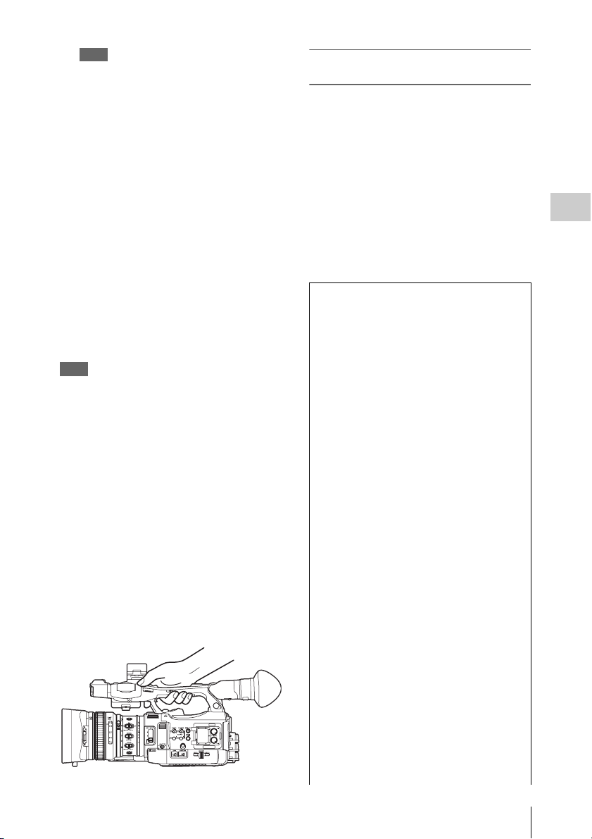
On holding the handle
When shooting by holding the handle, hold the
front end of the handle to keep the camcorder
steady.
Checking the last recorded clip (Rec
Review)
9 Press the REC REVIEW button.
The Rec Review function (page 40) is
activated, and the last recorded clip is played
back for the specified time on the LCD
monitor/EVF screen.
To delete clips
You can delete the last recorded clip by using the
Last Clip DEL function (page 54). Use the All
Clips DEL function (page 54) to delete all
recorded clips from an SxS memory card. To
specify a clip to be deleted, operate the camcorder
from the thumbnail screen (page 88).
Clip (recording data)
When you stop recording, video, audio and
subsidiary data from the start to end of the
recording are recorded as a single clip on an
SxS memory card.
Clip name
For each clip recorded with this camcorder, a
clip name is automatically generated according
to the method selected with “Auto Naming” in
(page 134)
“Clip”
The default setting of “A uto Naming” is “Plan.”
With this setting, a clip name defined in
planning metadata is applied if a planning
metadata file is loaded into the camcorder.
Change the “Auto Naming” setting to “Title” to
apply a clip name composed of 4 to 46
alphanumerics and 4 numerics.
Example: ABCD0001
The block of 4 to 46 alphanumerics can be
specified as desired using “Clip” in the
OTHERS menu before you start recording. (It
cannot be changed after recording.)
The value of the 4 numerics is automatically
counted up in sequence.
Notes on Clips
The maximum file size for a clip is 43 GB for
UDF and exFAT, 4 GB for FAT HD Mode, and
2 GB for FAT SD Mode. If you continue
recording for an extended period, recorded
materials may be segmented into multiple files,
depending on the file size (the maximum
number of partitions is 99). The camcorder
regards continuous recording as one clip even if
it has been segmented into multip le files in FAT
mode.
of the OTHERS menu.
Recording
Basic Operation Procedure
29
Page 30

A long clip can be recorded crossing over two
memory cards in slot A and B.
When you copy recorded clips to a hard disk,
etc., via computer, it is recommended to use the
dedicated application software, which you need
to download, to maintain the continuity of
recorded materials. For details, see “Software
Downloads” (page 186).
Note
If copying is done using Explorer (Windows) or
Finder (MAC), the continuity and relationships of
recorded materials may not be maintained.
Recording
Maximum duration of a clip
The maximum clip length is 24 hours for FAT
(MP4 or AVI) and 6 hours for UDF (MXF) and
exFAT (MXF).
If you exceed the maximum clip length, a new
clip will be automatically created. You can
check the new clip on the thumbnail screen.
Changing Basic Settings
You can make changes to the settings based on
the intended usage of the recorded video or
recording conditions.
Video Formats
Selectable formats vary depending on the UDF/
exFAT/FAT, HD Mode/SD Mode, and usage
region (NTSC Area/PAL Area) settings.
You can change the usage area by setting “Country”
in “System” (page 133) of the OTHERS menu.
Switching between UDF/exFAT/FAT
Switch by setting “F.Sys.” in “System” (page
133) of the OTHERS menu.
After switching this setting, the camcorder will
automatically restart.
Note
UDF/exFAT/FAT cannot be switched during recording
or playback.
Switching between HD Mode/SD Mode
For HD/SD switching, use “System” (page 133)
of the OTHERS menu.
After switching this setting, the camcorder will
automatically restart.
Note
HD/SD switching is disabled during recording and
playback.
Changing Basic Settings
30
Switching between XAVC/MPEG2
For XAVC/MPEG2 switching, use “System”
(page 133) of the OTHERS menu.
“XAVC/MPEG2” can be selected only when
“F.Sys.” of the OTHERS menu is set to “exFAT”
and “HD/SD” of the OTHERS menu is set to
“HD.”
Note
XAVC/MPEG2 switching is disabled during recording
and playback.
Page 31

Changing the format
To change the format, use “Format” in “System”
(page 133) of the OTHERS menu.
Signals from the SDI OUT, A/V OUT, and HDMI
OUT connectors are also output according to the
format selected with this menu.
ND Filter
ND filters are available for keeping the aperture
in a proper range.
1
/64ND
2:
1
1:
/8ND
CLEAR: ND filter not used
White Balance
You can select the adjustment mode according to
the shooting conditions.
Preset mode
The color temperature is adjusted to the preset
value (factory setting: 3200K) in this mode.
Select this mode when there is no time to adjust
the white balance or when you wish to fix the
white balance to the condition of you set for a
Picture Profile.
Memory A mode, Memory B mode
The white balance is adjusted to the value stored
in memory A or memory B.
Pressing the WHITE BAL button executes auto
white balance and stores the adjusted value in
memory A or memory B.
When the Wi-Fi remote commander is used and
the ATW function is set to off, the adjusted value
is changed to the one in memory A, irrespective
of the status of the WHITE BAL switch.
ATW (Auto-Tracing White balance) mode
In this mode, the camcorder automatically adjusts
the white balance to the appropriate condition.
When the color temperature of the light source
changes, the white balance adjustment is
automatically executed.
Five steps of adjustment speed can be selected
with “ATW Speed” (page 113) of the CAMERA
SET menu.
When the ATW Hold function is assigned to an
assignable button (page 40), you can
momentarily hold the ATW value to fix the white
balance, even in ATW mode, by pressing the
button.
Note
Under some conditions of lighting or the shooting
subject, adjustment by ATW may fail to provide proper
colors.
Examples:
• When the subject of a substantially single color like
sky, sea, ground, grass, or certain kinds of flowers
occupies most of the frame area.
• When the subject is under a light source of extremely
high or extremely low color temperature.
If execution of automatic tracing by the ATW function
takes an unacceptably long time or only results in an
inadequate effect, then execute the AWB function.
Using the switch
Make a selection with the WHITE BAL switch
(page 11).
B: ATW mode or Memory B mode
A: Memory A mode
PRST: Preset mode
The B position of the WHITE BAL switch is
assigned to ATW mode at the factory. The setting
can be changed with “White Switch <B>” (page
113) of the CAMERA SET menu to select
Memory B mode.
Setting the camcorder to Full Auto mode (page
28) forcibly activates ATW mode.
Assigning the ATW on/off function to an
assignable button (page 40) permits you to
independently activate/deactivate ATW when
Full Auto mode is off.
Using the Direct menu
When you press the DISPLAY button (page 10),
the current adjustment mode and color
temperature are displayed on the screen (page
14).
AT W: ATW mode
W:A : Memory A mode
W:B : Memory B mode
W:P : Preset mode
When the Direct menu (page 16) is in All mode,
you can select from among ATW, W:A, W:B, and
W:P.
When the Direct menu is in Part mode, you can
switch between ATW and the mode set with the
WHITE BAL switch.
When W:NS is displayed, switching via the
Direct menu is not possible.
Recording
Changing Basic Settings
31
Page 32

Using the assignable button
When recalling one of the picture profiles (PP1 to
PP6, 6 types) that are registered, you can switch
the preset color temperature from 4 types of
presets that are set on “Preset White” in “White”
by pressing the assignable button to which “WB
Preset” is assigned.
To set the preset color temperature
1 Press the PICTURE PROFILE button
(page 11).
Recording
The PICTURE PROFILE menu appears.
2 Select “SEL,” and select the picture
profile (PP1 to PP6).
3 Select “SET,” and select the preset
number 1, 2, 3, or 4 on “Preset White
Sel” in “White.”
4 Set the color temperature on “Preset
White” in “White.”
The color temperature of 1, 2, 3, or 4 that is
selected on “Preset White Sel” appears on
“Preset White.”
The default setting of the color temperature
for 1, 2, 3, or 4 that is selected on “Preset
White Sel” is as follows.
• 1 is selected for “Preset White Sel”: 3200K
• 2 is selected for “Preset White Sel”: 4300K
• 3 is selected for “Preset White Sel”: 5600K
• 4 is selected for “Preset White Sel”: 6300K
The color temperature can be set in step of
100K.
5 Press the SEL/SET button or the jog
dial after setting the color temperature.
6 Repeat Steps 3 to 5 to set the color
temperature for other preset number.
To operate by using the assignable button
1 Assign “WB Preset” to one of the
assignable buttons 1 to 5.
2 Select the preset mode by using the
WHITE BAL switch (page 11) or
operating on the Direct menu.
Note
When “Network Remote” is set to “On,” the
adjustment mode for white balance is set to the
Memory A mode and you cannot set to the preset
mode. To set to the preset mode, set “Network
Remote” to “Off.”
3 Press the assignable button to which
“WB Preset” is assigned.
The 4 preset color temperature settings that
are set on “To set the preset color
temperature” (page 32) are switched each
time you press the assignable button.
Note
The preset color temperature cannot be switched in the
following situations.
• When the adjustment mode for white balance is set to
the ATW mode, Memory A mode, or Memory B mode
• When “SEL” of “PICTURE PROFILE” is set to “Off”
• During playback, Rec Review, displaying the
thumbnail screen, displaying the color bars
• While performing ABB, AWB, Multi Matrix > Color
Detection, Color Correction > Area Indication, Skin
Tone Detail > Area Detection, APR, Auto FB, AWS,
or ABS
Executing Auto White Balance
1 To store the adjustment value in
memory, select Memory A or Memory
B mode.
2 Place a white subject under the same
lighting condition and zoom in on it so
that a white area is obtained on the
screen.
3 Adjust the brightness.
Adjust Iris as instructed in “Adjusting the
brightness manually” (page 34) below.
4 Press the WHITE BAL button (page 8).
When you execute the adjustment in a memory
mode, the adjusted value is stored in memory (A
or B) selected in step 1.
When you execute the adjustment in ATW mode,
adjustment in ATW is resumed.
Notes
• Auto white balance adjustment cannot be performed
when in Preset mode.
• If auto white balance adjustment fails, an error
message is displayed on the screen for approximately
3 seconds. If the error message continues to be
Changing Basic Settings
32
Page 33

displayed after several attempts, consult your Sony
service representative.
Markers/Zebra Patterns
During recording, various markers and zebra
patterns can be inserted into the image on the
LCD monitor/EVF screen.
This does not affect recording signals.
Displaying the Markers
Use “Marker” (page 120) of the LCD/VF SET
menu.
Displaying the Zebra Patterns
A zebra pattern(s) can be inserted to the picture
on LCD monitor/EVF screen to check the
appropriate luminance level.
Pressing the ZEBRA button (ASSIGN 1 button)
(page 11) turns the zebra pattern-indication on/
off.
When the Direct menu is in All mode, you can
change the gain in steps of 3 dB with the Direct
menu.
You can also select AGC mode with the Direct
menu.
When the Direct menu is in Part mode, you can
switch between only AGC mode and the gain
selected with the GAIN switch.
Recording in AGC Mode
The gain of the video amplifier is automatically
adjusted according to the picture brightness.
When you set the camcorder to Full Auto mode
(page 28), AGC mode is forcibly selected.
When Full Auto mode is off, you can
independently turn AGC mode on by setting
“AGC” in “TLCS” (page 113) of the CAMERA
SET menu to “On,” or selecting “AGC” with the
Direct menu.
Electronic Shutter
Recording
Changing the zebra pattern
Using “Zebra” (page 120) in the LCD/VF SET
menu, you can change the zebra pattern to be
displayed.
Gain
Recording with Fixed Gain
You can change the gain of the video amplifier.
Selecting the gain with the switch
The gain value at each of the GAIN switch (page
11) positions set at the factory are as follows:
L: 0 dB
M: 9 dB
H: 18 dB
These values can be changed in the range of
–3 dB to +18 dB, using the CAMERA SET
menu’s Gain Setup menu (page 108).
Note
You cannot select a fixed gain when AGC mode is set to
On.
Selecting gain using the Direct menu
When you press the DISPLAY button (page 10),
the current gain value is displayed on the screen
(page 14).
Recording with a fixed shutter
Set the shutter speed (cache time).
When you set the SHUTTER switch (page 11) to
ON, the fixed shutter is turned on in the mode and
with the shutter speed you specified with
“Shutter” (page 108) of the CAMERA SET
menu.
Notes
• When Auto Shutter mode is on, the fixed shutter
cannot be selected.
• When the SLS/EX SLS mode (page 34) is on, the fixed
shutter cannot be selected.
Setting with the CAMERA SET menu
The shutter mode and shutter speed can be set
with “Shutter” (page 108) of the CAMERA SET
menu.
Setting with the Direct menu
When you press the DISPLAY button, the current
shutter mode and the set value are displayed
(page 14).
When the Direct menu (page 16) is in All mode,
you can change the shutter mode and speed with
the Direct menu.
Notes
• When the Direct menu is in Part mode, you cannot tur n
the shutter off with the Direct menu if the SHUTTER
switch is set to ON.
Changing Basic Settings
33
Page 34

If the SHUTTER switch is set to OFF, you can switch
only between Auto Shutter and Shutter OFF.
• The Direct menu cannot be selected when Full Auto
mode is turned on (page 28) or when the SLS/EX SLS
mode is set.
Shooting in SLS/EX SLS Mode
The shutter speed is specified in the number of
accumulated frames. Up to 64 frames can be
accumulated in this mode, permitting you to
obtain low-noise clear pictures in low light levels
or surreal pictures with afterimages.
For SLS/EX SLS, specify the number of
Recording
accumulated frames with “SLS/EX SLS” (page
108) of the CAMERA SET menu. You can select
from 2 to 8, 16, 32, 64 frames.
When SLS/EX SLS is ON, you cannot set Full
Auto mode (page 28).
When Full Auto mode (page 28) is on or Auto
Shutter mode is on, and SLS/EX SLS is set to on,
Full Auto mode or Auto Shutter mode is
canceled.
Shooting in Auto Shutter Mode
The shutter speed is automatically adjusted
according to the picture brightness.
When you set the camcorder to Full Auto mode
(page 28), Auto Shutter is forcibly selected.
When Full Auto mode is off, you can
independently turn Auto Shutter mode on by
setting “Auto Shutter” in “TLCS” (page 113) of
the CAMERA SET menu to “On.”
Iris
Adjust the brightness according to the subject.
Recording in auto mode
When Full Auto mode (page 28) is set to on:
Iris is forcibly set to Auto mode.
When Full Auto mode is set to off:
When the IRIS switch is set to AUTO, Auto Iris
mode is set.
You can select the target level (to make the
picture darker or brighter) for Auto Iris via the
Setup menu or Direct menu. (The gain control in
AGC mode and the shutter speed control in Auto
Shutter mode are adjusted in synchronization.)
To adjust the target level with the Setup menu
Set “Level” in “TLCS” (page 113) of the
CAMERA SET menu.
To adjust the target level with the Direct menu
The target level can also be selected using the
Direct menu (page 16). When you press the
DISPLAY button, the current Exposure position
is displayed on the screen (page 14).
Adjusting the brightness manually
When Full Auto mode is set to off, setting the
IRIS switch to MANUAL sets to Manual Iris
mode. Rotate the iris ring for the desired iris
opening.
Switching to Auto Iris mode temporary
By pressing the assignable button to which “One
Push Auto Iris” is assigned during Manual Iris
mode, the One Push Auto Iris function is
activated. The One Push Auto Iris function is
activated while pressing the button. When the
button is released, the camcorder returns to
Manual Iris mode.
Zoom
Operating Zoom manually
Setting the ZOOM switch (page 13) on the
bottom of the camcorder to the MANUAL
position sets to manual zoom mode.
Using the Power Zoom
The power zoom lever (page 13) on the grip and
the on-handle ZOOM button (page 10) are
activated.
The supplied IR Remote Commander and
optional lens remote control unit can also be used.
Setting the ZOOM switch on the bottom of the
camcorder to the SERVO position sets to power
zoom mode.
The current zoom position is displayed on the
screen in the range of 0 (Wide) to 99 (Tele) when
you press the DISPLAY button.
The numerical indication can be changed to that
in a bar by changing “Zoom Position” in “Display
On/Off” (page 120) of the LCD/VF SET menu.
To adjust with the power zoom lever on the grip
Pressing the lever deeper sets zooming faster.
To adjust with the on-handle ZOOM button
You can select the zoom speed with “Handle
Zoom” (page 109) of the CAMERA SET menu.
The “Vari” setting enables faster zoom speed the
Changing Basic Settings
34
Page 35

deeper the on-handle ZOOM button is pressed as
in the case of the power zoom lever on the grip.
The zoom speed assignment can be changed with
“Zoom Speed” (page 109) of the CAMERA SET
menu.
You can select Soft mode for zooming by using
“Zoom Transition” (page 110) of the CAMERA
SET menu, in which the zooming speed is
gradually increased at the beginning then
gradually decreased for the end.
When adjusting with the ZOOM button of the IR
Remote Commander
The zooming speed depends on the “Remote”
(page 109) setting in “Zoom Speed” of the
CAMERA SET menu.
To use the IR Remote Commander, see “Using the IR
Remote Commander” (page 21).
When using a lens remote controller
Zooming can also be controlled from an optional
lens remote controller connected via the LENS
REMOTE connector.
For operation, refer to the operation guide of the lens
remote controller.
Focus
The infinity (∞ ) position has some margin to
compensate for focus change caused by variation
in ambient temperature. When shooting an image
at infinity in MF mode, adjust the focus while
observing the image on the LCD monitor/EVF
screen.
Adjusting in Full MF Mode
Pull the focus ring rearward (toward the
camcorder body) to set the camcorder to Full MF
mode. Focus can only be adjusted with the focus
ring manually.
Note
The focus instantly moves to the range index position
when you pull the focus ring rearward.
Rotate the focus ring for the best focus while
observing the picture on the LCD monitor/EVF
screen.
The range index of the focus ring is effective in
Full MF mode. The distances correspond to the
focus ring positions.
Focus Magnifier
When you press the FOCUS MAG button, the
center area of the picture is magnified on the LCD
monitor/EVF screen, making the focus
adjustment easier.
Press the FOCUS MAG button again or leave the
focus ring unmoved for 5 seconds to resume the
normal angle for recording.
Peaking
When you press the PEAKING button (ASSIGN
2 button), the peaking function is activated. This
function emphasizes the contours of the images
on the LCD monitor/EVF screen, making manual
focusing easier.
This function does not affect recording signals.
The emphasis level and color of the contours can
be set with “Peaking” (page 119) of the LCD/VF
SET menu.
Adjusting in MF Mode
MF (Manual Focus) mode allows you to activate
Auto Focus momentarily when required.
Slide the focus ring forward (to lens hood side),
then set the FOCUS switch (page 11) to
MANUAL.
In this mode, expanded focus function, peaking
function, one-push auto focus function, and the
MF Assist function are activated.
Rotate the focus ring while looking at the LCD
monitor/EVF screen to adjust the focus.
One-Push (Momentary) Auto Focusing
When you press the PUSH AUTO button, auto
focusing momentarily activates. One-Push Auto
Focusing is terminated when the subject comes
into focus.
MF Assist function
If you set “MF Assist” (page 109) of the
CAMERA SET menu to “On” to enable the MF
Assist function, auto focusing is engaged when
you stop rotating the lens operation ring,
performing fine focus adjustment for the subject
in the center of the screen. When the fine
adjustment is completed, automatic focusing with
the MF Assist function is terminated.
You can also enable the MF Assist function via
the Direct menu (page 16). When you press the
DISPLAY button, the selected focus mode is
displayed on the screen (page 14). The Direct
menu cannot be selected in a mode other than MF
mode.
Recording
Changing Basic Settings
35
Page 36

Adjusting in AF Mode
AF (Auto Focus) mode adjusts the focus
automatically.
Slide the focus ring forward, then set the FOCUS
switch to AUTO.
Using Macro Mode
When you set the MACRO switch to ON in AF or
MF mode, Macro mode is activated, permitting
you to adjust the focus in a range that includes the
macro area.
Recording
The Macro mode is invalid in Full MF mode.
Note
If the frame rate selected for recording is close to the
power-supply frequency, flicker may not be reduced
sufficiently even if you activate the Flicker-Reduction
function. In such cases, use the electronic shutter.
Time Data
Setting the Timecode
Specify the timecode to be recorded with
“Timecode” and “TC Format” of the TC/UB SET
menu (page 122).
Steady Shot
By activating the Steady Shot function, blurring
of images due to camera shaking can be reduced.
Press the STEADY SHOT button on the
lens.
Pressing the button turns the Steady Shot function
on or off.
The setting of the Steady Shot function is
displayed in the EVF screen.
Note
If the camcorder is fixed to a tripod for stable
condition, deactivate the Steady Shot function.
Flickers
Setting the shutter speed according to
the power-supply frequency
Activate the electronic shutter (page 33) and set
the shutter speed according to the power supply
frequency.
When the frequency is 50 Hz
Set the shutter speed to 1/50 or 1/100 seconds.
When the frequency is 60 Hz
Set the shutter speed to 1/60 or 1/120 seconds.
Setting the Users Bit
You can add a hexadecimal number of 8 digits for
pictures as the user bits.
The user bits can also be set to the current date.
Use “Users Bit” (page 122) of the TC/UB SET
menu.
Displaying the Time Data
Pressing the DISPLAY button displays the time
data on the screen (page 14).
The indication is switched among the timecode,
user bits, and recording duration each time you
press the DURATION/TC/U-BIT button (page
10).
Display Contents
TCG **:**:**:** Timecode
CLK **:**:**:** Timecode (Clock mode)
UBG ** ** ** ** User bits
DUR **:**:** Duration from the beginning of
recording
Using the Flicker-Reduction function
Set “Mode” in “Flicker Reduce” (page 109) of the
CAMERA SET menu to “Auto” or “On” and set
“Frequency” to the power-supply frequency (50
Hz or 60 Hz).
Changing Basic Settings
36
Page 37

Recording Audio Signals
2 Attach a microphone, then return the
external microphone holder cover to its
original position to secure it.
Four channels (CH-1/C H-2/CH-3/CH-4) of audio
can be recorded (Linear PCM recording) in
synchronization with video recording.
You can use the built-in stereo microphones
(omni-directional electret condenser
microphones) or 2-channel external audio inputs
to the AUDIO IN connectors by switching with
the AUDIO IN switches.
Using the Built-in Stereo Microphones
Set the AUDIO IN switches, both CH-1 and
CH-2 (page 11), to INT.
Using External Inputs
1 Set the CH-1 and CH-2 AUDIO IN
switches (page 11) to EXT.
2 Connect external audio sources to the
AUDIO IN connectors CH-1 and CH-2
(page 9).
3 Set “CH1 EXT Input” and “CH2 EXT
Input” in “Audio Input” of the AUDIO
SET menu to “XLR” (page 115).
4 Set the input (LINE/MIC/MIC+48V)
switches CH-1 and CH-2 (page 9) to
LINE (line level: +4 dBu).
Note
When using XLR input connector, set “CH1 EXT Input”
or “CH2 EXT Input” in “Audio Input” of the AUDIO
SET menu to “XLR”.
Using an External Microphone
You can use an external microphone for
recording, such as the ECM-673 Electret
Condenser Microphone.
1 Lift up the handle of the external
microphone holder (page 9) and open
the cover.
3 Connect the microphone cable to the
AUDIO IN CH-1/CH-2 connectors.
External
microphone
to AUDIO IN
Cable
clamp
4 Set the corresponding AUDIO IN
switch (CH-1/CH-2) (page 11) to EXT.
5 Set “CH1 EXT Input” and “CH2 EXT
Input” in “Audio Input” of the AUDIO
SET menu to “XLR” (page 115).
6 Set the corresponding input (LINE/
MIC/MIC+48V) switch (CH-1/CH-2)
(page 9) according to the connected
microphone.
MIC: For a microphone that requires no
power supply
MIC +48V: For a microphone that requires
+48V power supply (such as the ECM-
673)
Note
When using XLR input connector, set “CH1 EXT Input”
or “CH2 EXT Input” in “Audio Input” of the AUDIO
SET menu to “XLR”.
Using a microphone compatible with the Multi
Interface Shoe
1 Set the CH-1 and CH-2 AUDIO IN
switches to EXT.
2 Attach a microphone to the Multi
Interface Shoe
Recording
Recording Audio Signals
37
Page 38

3 Set “CH1 EXT Input” and “CH2 EXT
Input” in “Audio Input” of the AUDIO
SET menu to “SHOE MIC” (page 115).
Notes
• The action of the Multi Interface Shoe differs
depending on the used power source, AC adaptor (BCU1, BC-U2), or the battery pack.
When using the AC adaptor (BC-U1, BC-U2)
—When a Network function is used, no power is
supplied to the Multi Interface Shoe.
—When using the wireless microphone UWP-D11/
D12, set “NW&Proxy/USB” to values other than
“Network&Proxy.”
—Connect the wireless microphone UWP-D11/D12
Recording
with the XLR input connector of this unit when
using a Network function and wireless
microphone UWP-D11/D12 simultaneously.
In this case, use the wireless microphone UWPD11/D12 with a battery pack as no power is
supplied to the Multi Interface Shoe.
When using a battery pack
—The power is supplied to the Multi Interface Shoe
and the wireless microphone UWP-D11/D12 can
be used.
• When “CH1 EXT Input” and “CH2 EXT Input” in
“Audio Input” of the AUDIO SET menu are set to
“SHOE MIC,” the settings for the CH-1 and CH-2
input (LINE/MIC/MIC+48V) switches are disabled.
Any position is set to equivalent to MIC.
Adjusting the Audio Recording Levels
No audio recording is made in Slow & Quick
recording if the recording frame rate is set to a
value different from the playback frame rate.
Monitoring the Audio
You can monitor the sounds being recorded with
the headphones connected to the headphone
connector (stereo mini jack) (page 8).
Note
The built-in speaker is disabled during recording (or
when standing by to record).
To adjust the audio monitoring volume
Use the VOLUME buttons (page 10).
To adjust the levels automatically (AGC)
When the AUDIO SELECT switches CH-1 and
CH-2 (page 11) are set to AUTO, the audio
recording levels are automatically adjusted.
To adjust the levels manually
Set the AUDIO SELECT switches CH-1 and CH2 to MANUAL and adjust the audio recording
levels by turning the AUDIO LEVEL knobs
(page 11).
Set the controls to 5 for the reference setting (0
dB). Setting to 10 maximizes the level (+12 dB),
and setting to 0 minimizes it (–
∞ ).
The input levels are displayed on the screen when
you press the DISPLAY button (page 14).
Audio recording in special recording
modes
No audio recording is made in Interval Recording
or Frame Recording.
Recording Audio Signals
38
Page 39

Useful Functions
Color Bars/Reference Tone
By setting “Camera/Bars” in “Color Bars” (page
109) of the CAMERA SET menu to “Bars,” you
can output a color-bar signal in place of the
camera picture. When this item is set to
“Camera,” the output returns to the camera
picture.
A 1-kHz reference tone is output with the color
bar signal if “1KHz Tone” in “Audio Input” (page
115) of the AUDIO SET menu is set to “On.”
The color-bar signal and reference-tone signal are
also fed out from the SDI OUT, HDMI OUT,
i.LINK, VIDEO OUT (color bars only), and A/V
OUT connectors.
You can select the type of color bars with “Bars
Type” in “Color Bars” of the CAMERA SET
menu.
Notes
• The color bar mode cannot be output in Slow & Quick
Motion mode and SLS/EX SLS mode.
• You cannot switch to “Color Bars” while recording.
(Switching from “Color Bars” to “Camera” is
available.)
Shot Marks
When you record shot marks for important scenes
of a clip recorded in UDF, exFAT, or FAT HD
Mode as subsidiary data, you can access the
ma rk ed p oi nts ea sil y o n a S ho t Ma rk scr ee n (page
96), which only displays scenes with shot marks
only. This increases editing efficiency.
The camcorder permits yo u to record two types of
shot marks: shot mark 1 and shot mark 2.
Shot marks can be recorded as needed during
recording or can be added after recording while
checking the playback pictures on the thumbnail
screen.
Inserting a shot mark during recording
If the Shot Mark1 or Shot Mark2 function is
assigned to an assignable button (page 40), press
the button where you want to insert a shot mark.
For operations to add shot marks after recording,
see “Adding Shot Marks During Playback (UDF,
exFAT, and FAT HD Mode)” on page 91 and
“Adding/Deleting Shot Marks (UDF, exFAT, and
FAT HD Mode)” on page 97.
For operation to apply a name to a shot mark, see
“Defining Shot Mark names in Planning Metadata”
on page 58.
OK/NG/KP Flags (UDF and exFAT)
You can add OK/NG/KP flags to clips recorded
with UDF or exFAT. By adding flags, you can set
the camcorder to display only clips with certain
flag settings on the thumbnail screen “OK/NG/
KP/None-Clip thumbnail screen” (page 89).
Note
Use the “Lock Clip” setting (page 92) to protect clips.
Adding a flag
During recording or playback, press the
assignable button to which you assigned the
Clip Flag OK/Clip Flag NG/Clip Flag Keep
function.
You can add an OK/NG/KP flag to a clip during
recording or playback.
Deleting a flag
Press the assignable button, twice in
succession, to which you assigned the Clip
Flag OK/Clip Flag NG/Clip Flag Keep
function.
You can delete the OK/NG/KP flag from a clip.
OK/NG/KP flags can also be added and deleted from
the thumbnail screen. For details, see “Adding/
Deleting a Flag (UDF and exFAT)” (page 94).
Recording
OK Mark (FAT HD Mode Only)
By adding the OK mark to a clip recorded in FAT
HD Mode, you can prevent the clip from being
deleted or divided inadvertently. You can also set
the camcorder to display only clips with the OK
Useful Functions
39
Page 40

mark on the thumbnail screen “OK-Clip
thumbnail screen” (page 89).
Adding the OK mark
When recording of a clip ends, press the
assignable button to which you assigned the
OK Mark function.
While standing by to record, you can also add an
OK mark to the last-recorded clip (“Last Clip”)
on the selected memory card.
Deleting the OK mark
Recording
Press the assignable button to which you
assigned the OK Mark function, and select
“Execute.”
While standing by to record, you can also delete
the OK mark from the clip with the last-added OK
mark.
Adding or deleting the OK mark to or from
clips before the last one
Make changes via the thumbnail screen.
For details on maki ng settings, see “Adding/Deleti ng
the OK Mark (FAT HD Mode Only)” (page 94).
• If the video format was changed after recording, Rec
Review cannot be performed (except when the change
was from SP 1440×1080/23.98P to SP 1440×1080/
59.94i).
• The Setup and PICTURE PROFILE menus cannot be
operated during Rec Review.
Assignable Buttons
The camcorder has five assignable buttons (page
11) to which you can assign various functions for
convenience.
To change functions
Use “Assign Button” (page 131) of the OTHERS
menu.
The assigned functions can be viewed on the
“Button/Remote Status Screen” (page 99).
Interval Recording
The Interval Recording (time-lapse recording)
function is especially effective for shooting
objects that move very slowly.
The specified number of frames are automatically
recorded at the specified intervals.
Recording interval (Interval Time)
Rec Review
You can review the last recorded clip on the
screen (Rec Review).
Press the REC REVIEW button (page 13)
after recording is finished.
If the Rec Review function is assigned to an
assignable button (page 40), you can also use that
button.
The last 3 seconds, 10 seconds, or the entire part
of the clip is displayed, depending on the “Rec
Review” setting (page 113) of the CAMERA
SET menu.
Rec Review is terminated at the end of the clip,
resuming STBY (recording standby) status.
To interrupt Rec Review
Press the REC REVIEW or STOP/CAM button
or the assignable button to which you assigned the
Rec Review function.
Notes
• During Rec Review playback, the playback control
buttons other than the STOP/CAM bu tton are disabled.
Useful Functions
40
Number of frames for one recording session
(Number of Frames)
It is recommended to fix the camcorder to a tripod
or equivalent and use the IR Remote Commander
to start/stop recording rather than pressing the
REC START/STOP button of the camcorder.
Notes
• Audio cannot be recorded in Interval Recording mode.
• Interval Recording cannot be set to “On”
simultaneously with Frame Recording, Picture Cache
Recording, Slow & Quick Motion, Clip Continuous
Recording, Simultaneous Recording in the 2 slots, or
Proxy Recording. When you set Interval Recording to
“On,” these other functions are forcibly set to “Off.”
Page 41

• Interval Recording mode cannot be used when
“Format” in “System” (page 133) of the OTHERS
menu is set to “HQ 1280×720/23.98P” (in UDF HD
Mode and FAT HD Mode) or “SP 1 440×1080/23.98P”
(in FAT HD Mode).
• Interval Recording mode cannot be used when the
items “DVCAM” or “HDV” are set for “SDI/HDMI/
i.LINK I/O Select” (page 117) of the VIDEO SET
menu, and the video format of “Format” in “System”
(page 133) of the OTHERS menu is set to other than
“HQ mode/23.98P.”
Preparatory settings
Before starting Interval Recording, make the
necessary settings of the CAMERA SET menu
(page 110) in advance.
When the video light compatible with the Multi
Interface Shoe is mounted, you can set “PreLighting” in “Inte rval Rec” of the CAMERA SET
menu to “On” so that the light turns on
automatically approximately 2 seconds before
recording.
Notes
• While “Pre-Lighting” is set to “On”, the video light
remains on with “Interval Time” set to “3sec” or less,
even if “Rec Link” or “Rec Link + Stby” in “Video
Light Set” is set.
• While “Pre-Lighting” is set to “Off,” the video light
remains off, even if you start recording with “Rec
Link” in “Video Light Set” set. If “Rec Link + Stby” in
“Video Light Set” is set, the video light remains dimlylit.
Performing Interval Recording
When the preparatory settings are completed, you
can start recording.
Press the REC START/STOP button.
Notes
• You cannot change the “Interval Time” and “Number
of Frames” settings while Interval Recording is in
progress. To change them, pause recording.
• After starting Interval Recording, Rec Review
operation is disabled, even during an interval.
• The timecode is recorded in Rec Run mode (page 122)
during Interval Recording.
• Some extra frames may be recorded if you stop
recording or switch the card slot while recording is
halted in Interval Recording mode.
• “Setting” for “Interval Rec” is automatically set to
“Off” when you set the power switch to OFF, while the
“Interval Time” and “Number of Frames” settings are
maintained.
Frame Recording
The Frame Recording function is especially
effective for clay animation recording.
The specified number of frames are recorded
intermittently when you press the REC START/
STOP button.
It is recommended to fix the camcorder to a tripod
or equivalent and use the IR Remote Commander
to start/stop recording rather than pressing the
REC START/STOP button of the camcorder.
Notes
• Audio cannot be recorded in Frame Recording mode.
• Frame Recording cannot be set to “On” simultaneously
with Interval Recording, Picture Cache Recording,
Slow & Quick Motion, Clip Continuous Recording,
Simultaneous Recording in the 2 slots, or Proxy
Recording. When you set Frame Recording to “On,”
these other functions are forcibly set to “Off.”
• Frame Recording mode cannot be used when “Form at”
in “System” (page 133) of the OTHERS menu is set to
“HQ 1280×720/23.98P” (in UDF HD Mode and
exFAT HD Mode) or “SP 1440×1080/23.98P” (in
FAT HD Mode).
• Frame Recording mode cannot be used when the items
“DVCAM” or “HDV” are set for “SDI/HDMI/i.LINK
I/O Select” (page 117) of the VIDEO SET menu, and
the video format of “Format” in “System” (page 133)
of the OTHERS menu is set to other than “HQ mode/
23.98P.”
Preparatory settings
Before starting Frame Recording, make the
necessary settings of the CAMERA SET menu
(page 110) in advance.
Performing Frame Recording
When the preparatory settings are completed, you
can start recording.
1 Press the REC START/STOP button.
When the number of frames you specified
with the menu are recorded, the camcorder
automatical ly enters FRM ST BY (Frame Rec
Standby) status.
2 Press the REC START/STOP button
again.
Each time you press the REC START/STOP
button, the camcorder records the specified
number of frames then enters FRM STBY
status.
Recording
Useful Functions
41
Page 42

Notes
• Recording cannot be stopped until the specified
number of frames are recorded. If the power switch is
set to OFF during recording, the power is only shut off
after the specified number of frames are recorded.
• The Rec Review function cannot be used while
recording in Frame Rec mode is in progress.
• You cannot change the “Number of Frames” setting
while recording in Frame Rec mode is in progress. To
change it, pause the recording.
• The timecode is recorded in Rec Run mode (page 122)
during Frame Recording.
• Some extra frames may be recorded if you stop
recording or switch the card slot while recording is
paused in Frame Rec mode.
Recording
• “Setting” for “Frame Rec” is automatically set to “Off”
when you set the power switch to OFF, while the
“Number of Frames” setting is maintained.
• When the video light compatible with the Multi
Interface Shoe is mounted, the video light remains off
during recording, even if “Rec Link” in “Video Light
Set” is set. If “Rec Link + Stby” in “Video Light Set”
is set, the video light remains dimly-lit.
Clip Continuous Recording (UDF and exFAT)
Clips are normally created individually for each
time you start and sto p recording, but you can also
continue recording to a single clip regardless of
the number of times you start and stop recording
by using the Clip Continuous Recording function,
which will add recordings to the same clip until
the function is disabled or turned off.
This is convenient for when you do not want to
create a large number of short clips, or when you
do not want to be restricted by a maximum
number of clips.
A recording start mark is added to each point at
which you resume recording, making it easy to
search for each point.
Preparatory settings
Before starting Clip Continuous Recording, make
the necessary settings to “Clip Cont. Rec” (page
110) of the CAMERA SET menu in advance.
When you set “Setting” to “On,” the Clip
Continuous Recording function is enabled, and
“CONT” appears on the screen (page 14).
You can also assign “Clip Cont. Rec” to an
assignable button (page 40), and set “Setting” to
“On”/“Off” by pressing the button.
Notes
• Clip Continuous Recording cannot be set to “On”
simultaneously with Picture Cache Recording, Interval
Recording, Frame Recording, Slow & Quick Motion,
Simultaneous Recording in the 2 slots, or Proxy
Recording. When you set Clip Continuous Recording
to “On,” these other functions are forcibly set to “Off.”
• Clip Continuous Recording cannot be used while
recording.
• This function cannot be used with FAT.
Performing Clip Continuous Recording
When the preparatory settings are completed, you
can start recording.
Press the REC START/STOP button.
When recording starts, the “CONT” indication on
the screen changes to “zREC” (with z in red).
Notes
• If you remove the SxS memory card or the battery
while recording or standing by to record (the “CONT”
indication appears), the SxS memory card must be
restored. Only remove the SxS memory card after Clip
Continuous Recording is complete. If “CONT” is
flashing (1 time per second), you can remove the SxS
memory card.
• Record for at least 2 seconds before you stop
recording.
To disable Clip Continuous Recording mode
While standing by to record, set “Setting” in
“Clip Cont. Rec” (page 110) of the CAMERA
SET menu to “Off.”
Restricted Operations
If you perform any of the following operations
while recording or standing by to record, 1
continuous clip will not be created. The next time
you start recording, a new clip will be created.
• Performing clip operations (locking, deleting,
or changing the names of clips).
• Switching the memory card slot.
• Changing the recording format.
• Setting the power switch to OFF.
• Displaying the thumbnail screen.
• Playing clips.
Picture Cache Recording: Retroactively Record
When the Picture Cache Recording function is
active, the camcorder stores the last few seconds
of video captured in the built-in cache memory to
permit you to start recording video on an SxS
memory card from a point before you press the
Useful Functions
42
Page 43

REC START/STOP button. The maximum
picture cache time is 15 seconds.
Notes
• Picture Cache Recording cannot be set to “On”
simultaneously with Frame Recording, Interval
Recording, Slow & Quick Motion, Clip Continuous
Recording, Simultaneous Recording in the 2 slots, or
Proxy Recording. When you set Picture Cache
Recording to “On,” these functions are forcefully
disabled.
• Picture Cache Recording mode cannot be used while
recording, or while using Recording Review or Freeze
Mix.
• Picture Cache Recording is set to “Off” when you
change any of the settings in “System” (page 133) of
the OTHERS menu.
• When Picture Cache Recording is “On,” the time code
is always recorded in Free Run mode regardless of the
TC/UB SET menu settings (page 122).
• When “Format” in “System” of the OTHERS menu is
set to XAVC-I, the Picture Cache time can be set up to
4 seconds.
Preparatory settings
Before starting Picture Cache Recording, set
“P.Cache Rec” (page 110) of the CAMERA SET
menu.
“Setting” for Picture Cache Recording can also be
set to “On”/“Off” by assigning it to an assignable
button (page 40) and using that button.
When the setting has been made, the special
recording/operation status indication block on the
screen shows “zCACHE,” with z in green
(page 14).
Performing Picture Cache Recording
Press the REC START/STOP button.
Recording begins, and stored video in the cache
memory is written first to the SxS memory card.
The on-screen “
“
zREC” (z is red).
To cancel the Picture Cache Recording function
Set “Setting” in “P.Cache Rec” of the CAMERA
SET menu to “Off” or press the assignable button
to which you assigned the Picture Cache function.
Notes
• If you change the recording format, the cached data are
cleared and caching is newly started. Therefore, data
cached before you changed the format cannot be
recorded if you start Picture Cache Recording
immediately after changing the format.
• If you start/stop Picture Cache Recording immediately
after you insert an SxS memory card, data may not be
recorded on the card.
zCACHE” indication changes to
• Picture caching starts when you activate the Picture
Cache Recording function. Therefore, video before the
function is activated cannot be recorded with Picture
Cache Recording.
• Picture Cache Recording is invalid for external input
signal (HDV).
• As picture caching is disabled while an SxS memory
card is being accessed, such as during playback, Rec
Review, or thumbnail screen display, Picture Cache
Recording of such a period cannot be made.
• Although you can change the cache time setting while
recording, any new value becomes valid only after
recording has stopped.
• When the video light compatible with the Multi
Interface Shoe is mounted, retroactively recording
before the start of recording is not supported, even if
“Rec Link” or “Rec Link + Stby” in “Video Light Set”
is set. The video light is turned on/off when the REC
START/STOP button is pressed.
Slow & Quick Motion
When the cam corder is in UDF HD Mod e, exFAT
HD Mode, or FAT HD Mode and the video
format (page 133) is set to one of the following
settings, you can set the recording frame rate and
playback frame rate to different values.
NTSC Area
HD422 50/1080/29.97P
HD422 50/1080/23.98P
HD422 50/720/59.94P
HD422 50/720/29.97P
HD422 50/720/23.98P
XAVC-I 1080/29.97P
XAVC-L50 1080/29.97P
XAVC-L35 1080/29.97P
XAVC-I 1080/23.98P
XAVC-L50 1080/23.98P
XAVC-L35 1080/23.98P
XAVC-I 720/59.94P
XAVC-L50 720/59.94P
HQ 1920×1080/29.97P
HQ 1920×1080/23.98P
HQ 1280×720/59.94P
HQ 1280×720/29.97P (FAT HD Mode only)
HQ 1280×720/23.98P (FAT HD Mode only)
PAL Area
HD422 50/1080/25P
HD422 50/720/50P
HD422 50/720/25P
XAVC-I 1080/25P
XAVC-L50 1080/25P
XAVC-L35 1080/25P
XAVC-I 720/50P
XAVC-L50 720/50P
Recording
Useful Functions
43
Page 44

HQ 1920×1080/25P
HQ 1280×720/50P
HQ 1280×720/25P (FAT HD Mode only)
Notes
• Slow & Quick Motion recording cannot be used in SD
Mode.
• Slow & Quick Motion cannot be set to “On”
simultaneously with Frame Recording, Interval
Recording, Picture Cache Recording, Clip Continuous
Recording, Simultaneous Recording in the 2 slots, or
Proxy Recording. When you set Slow & Quick Motion
to “On,” these other functions are forcibly set to “Off.”
• Slow & Quick Motion mode cannot be used while
recording, or while using Recording Review or Freeze
Recording
Mix.
• Slow & Quick Motion mode cannot be used when
“SLS/EX SLS” (page 108) of the CAMERA SET
menu is set to other than “OFF.”
• Audio cannot be recorded when the recording and
playback frame rates differ.
Preparatory settings
Before starting Slow & Quick Motion recording,
set “S&Q Motion” (page 111) of the CAMERA
SET menu.
When the special recording mode indication on
the screen is active, “S&Q Motion” is displayed
on the screen (page 14).
Setting the recording frame rate with the Direct
menu
When the special recording mode indication on
the screen is active, [Recording frame rate]/
[Playback frame rate fps] is displayed under
“S&Q Motion.”
You can change the recording frame rate with the
Direct menu (page 16).
Recording in Slow & Quick Motion Mode
When the preparatory settings are completed, you
can start recording.
Press the REC START/STOP button.
Notes
• You cannot change the Frame Rate settings while Slow
& Quick Motion recording is in progress. To change
them, pause the recording.
• The timecode is recorded in Rec Run mode during
Slow & Quick Motion recording (page 122).
• When recording at a low-speed frame rate, it may take
time until recording stops after you press the REC
START/STOP button.
• Slow & Quick Motion mode is automatically set to
“Off” when you set the camcorder’s power switch to
OFF. However, the Frame Rate setting is saved.
Simultaneous Recording in the 2 slots
Simultaneous recording is available using both
memory card A and B.
Preparatory settings
Before starting Simultaneous Recording in the 2
slots, set “Simul Rec” in the CAMERA SET
menu to “Simul” (page 112).
Notes
• When using Simultaneous Recording in the 2 slots, use
memory cards with the same type and size.
• Using SxS memory cards is recommended.
• SDHC cards are not supported for using Simultaneous
Recording in 2 slots.
Compatible media
SxS PRO+ Series
SxS PRO Series
SxS-1 Series
XQD Memory Card Series
SDXC Card (exFAT Mode only)
Compatible format
When any of the following formats for the exFAT
HD mode is set in “System” of the OTHERS
• XAVC-I
• XAVC-L50
• XAVC-L35
• XAVC-L25
• MPEG2 HD422
• MPEG2 HD420HQ
When any of the following formats for the UDF/
HD mode is set in “System” of the OTHERS
• MPEG2 HD422
• MPEG2 HD420HQ
For details, refer to “Video Format (Format)” (page
150).
Recording in Simultaneous Recording in
the 2 slots mode
When the preparatory settings are completed, you
can start recording.
Press the REC START/STOP button.
The operations of recording start/stop are the
same as those of normal recording.
Useful Functions
44
Page 45

Notes
• Simultaneous Recording in the 2 slots cannot be set to
“On” simultaneously with the following functions.
—Frame Recording,
—Clip Continuous Recording,
—Picture Cache Recording,
—Slow & Quick Motion,
—Interval Recording
—Proxy Recording
—Network connection (NW&Proxy/USB is set to
Network&Proxy)
—Streaming
• Simultaneous Recording in the 2 slots cannot be set
while recording, playing back or displaying thumbnail
screen.
• When a memory card in one slot becomes full, if a
memory card in the other slot is recordable, recording
continues as normal recording. When you switch the
memory card during continuous recording as normal
recording, simultaneous recor ding or relay recording is
not available.
• When you start recording with Simultaneous
Recording in the 2 slots, if only one memory card is
inserted in either of slots or one of memory cards is
full, recording starts in a recordable memory card.
Freeze Mix: Image Alignment
In UDF HD Mode, exFAT Mode, or FAT HD
Mode, an image (still picture) of a recorded clip
can be temporarily superimposed on the current
camera picture, permitting you to easily align
images for your next recording.
To use the Freeze Mix function
Assign the Freeze Mix function to one of the
assignable buttons in advance (page 40).
Superimposing a Freeze Mix image
While recording or reviewing images by pressing
the REC REVIEW button, press the ASSIGN
button to which you assigned “Freeze Mix” at the
image with which you want to align. The image is
displayed as a still picture over the current camera
picture.
Canceling Freeze Mix status
You can cancel it with the ASSIGN button to
which you assigned “Freeze Mix” or the REC
START/STOP button.
When you cancel Freeze Mix status by pressing
the ASSIGN button, the normal camera picture is
displayed.
When you cancel Freeze Mix status by pressing
the REC START/STOP button, normal recording
begins.
Notes
• The Freeze Mix function cannot be used in SD Mode.
• Freeze Mix cannot be used when “Format” in
“System” (page 133) of the OTHERS menu is set to
“HQ 1280×720/23.98P” (in UDF HD Mode and
exFAT HD Mode) or “SP 1440×1080/23.98P” (in
FAT HD Mode).
• If the “Format” setting of the recorded picture and the
current camera picture differ, the Freeze Mix display
cannot be achieved.
• The Freeze Mix display cannot be obtained in Slow &
Quick Motion mode or Slow Shutter mode.
• You cannot operate the Setup menus and PICTURE
PROFILE menu in Freeze Mix status.
Automatic Adjustment of Flange Focal Length
When automatic adjustment of flange focal
length is activated, focusing is performed both at
the wide-angle and telephoto ends of the zoom for
flange focal length adjustment and the result is
stored so th at the in-focus condition is maintained
even if you change the zoom position after
focusing.
Notes
• If a subject of insufficient contrast is used, or if the
camcorder or subject moves during the adjustment,
adjustment cannot be made properly. Once the
adjustment begins, do not touch the camcorder body or
lens until it ends.
• Set “SLS/EX SLS” of the CAMERA SET menu to
“OFF” before starting the adjustment.
• Be careful that no light source, such as a lamp, the sun,
or a bright window, is in field of view during flange
focal length adjustment.
• Contact your dealer if a flange focal length adjustment
chart is required.
1 Set the power switch to ON.
2 Set the ND FILTER switch to CLEAR.
3 Place a high-contrast subject, such as a
flange focal length adjustment chart,
about 3 m (10 ft.) away from the
camcorder, and light it well enough to
provide a sufficient video output level.
Recording
Useful Functions
45
Page 46

Frame the subject so that it is located in the
center at the te lephoto end of the zoom. Make
sure that any object located closer to the lens
than the subject is out of frame at the wideangle end.
4 Set the ZOOM switch on the bottom of
the camcorder to SERVO (Power Zoom
mode).
5 Set “Auto FB Adjust” of the CAMERA
SET menu to “Execute” in the setup
Recording
menu, then press the SEL/SET button
or the jog dial.
The adjustment begins.
During adjustment, the in-progress message
is displayed.
When the adjustment finished, the
completion message is displayed.
Notes
• “Auto FB Adjust” cannot be selected when the ND
filter is set to 1 or 2.
• Do not change the ND filter while “Auto FB Adjust” is
in operation.
If you press the CANCEL button during
adjustment
Automatic adjustment of the fla nge focal length is
aborted and the condition before starting the
adjustment is resumed.
If the adjustment fails
An error message is displayed.
Check the conditions of the subject and lighting
then perform the adjustment again.
Picture Profiles
You can customize the picture quality, depending
on the conditions or circumstances of recording,
and store settings as a picture profile, enabling
you to recall the profile as necessary.
Six different picture profiles (PP1 to PP6) can be
stored in memory.
The same standard (reference) values are
registered to six picture profiles at the factory as
those specified for the Picture Profile Off status.
Note
Picture profiles can be set while recording or standing by
to record. They cannot be operated from the thumbnail
screen.
Registering the customized settings as a
Picture Profile
1 Set the power switch (page 8) to ON to
turn on the camcorder.
2 Press the PICTURE PROFILE button
(page 11).
The PICTURE PROFILE menu is displayed.
3 Using the up/down/left/right buttons or
the jog dial, select “SEL,” then press the
SEL/SET button or the jog dial.
4 Select the number of the picture profile
to register from the list, then press the
SEL/SET button or the jog dial.
5 Use the up/down buttons or the jog dial
to select “SET,” then press the SEL/
SET button or the jog dial.
6 Make each setting (page 47).
7 When the settings have been made,
press the PICTURE PROFILE button.
Selecting a registered Picture Profile
Once you store a picture profile, you can recall
the picture quality registered in the picture
profile.
1 While standing by to record, press the
PICTURE PROFILE button (page 11).
The PICTURE PROFILE menu is displayed.
2 Using the up/down/left/right buttons or
the jog dial, select “SEL,” then press the
SEL/SET button or the jog dial.
3 Select the number of the picture profile
to use from the list, then press the SEL/
SET button or the jog dial.
If OFF is selected, the picture quality is set to
standard and cannot be changed.
4 Press the PICTURE PROFILE button.
The picture profile being selected is displayed
when you press the DISPLAY button (page 14).
You can also select picture profiles with the
Direct menu (page 16).
Useful Functions
46
Page 47

Picture Profile Items
The values when “Off” is selected at “SEL” of the PICTURE PROFILE menu are shown in bold face
(example:
PICTURE PROFILE SET
Items Subitems and setting values Contents
Profile Name
Changing the picture profile
name
Matrix
Adjusting the color phase
over the entire area with
matrix operations
Multi Matrix mode
Selecting multi-matrix
correction and color phase
adjustment for the specified
area
Standard).
Profile name
Standard
Setting
On / Off
Set the profile name in 8 characters at maximum.
You can use upper- and lowercase alphabetics,
numerics 0 to 9, - (hyphen), _ (underscore) and
space.
Set to “On” to activate the color phase adjustment
function with matrix operations for the entire
picture.
Notes
• When this function is set to “Off,” Multi Matrix is
also set to “Off” in synchronization.
• If color saturation occurs under lighting that
contains excessive blue components (such as blue
LED lighting), set the “Setting” of “Matrix” to
“Off” to reduce the color saturation.
Select
1 / 2 / 3 / 4 / 5 / 6
Level
–99 to +99 (±0)
Phase
–99 to +99 (±0)
R-G, R-B, G-R, G-B, B-R, B-G
–99 to +99 (±0)
Multi Matrix / Color Correction Select the setting items of the Multi Matrix or the
Select the built-in preset matrix provided for
convenience.
1: Equivalent to SMPTE-240M / 2: Equivalent to
ITU-709 / 3: Equivalent to SMPTE WIDE / 4:
Equivalent to NTSC / 5: Equivalent to EBU / 6:
Equivalent to PAL
Adjust the color saturation for the entire picture
area.
Adjust the hue for the entire picture area.
Finely adjust the color phase for the entire picture
area by independently setting each of the factors.
setting items of the Color Correction.
Recording
Useful Functions
47
Page 48

PICTURE PROFILE SET
Items Subitems and setting values Contents
Multi Matrix
Makes settings related to
multi-matrix correction.
(Unselectable when “Color
Correction” is selected in the
Multi Matrix mode)
Recording
Color Correction
Adjusting the color phase in
a specific area (Unselectable
when “Multi Matrix” is
selected in the Multi Matrix
mode)
Setting
On / Off
Area Indication
On / Off
Color Detection
Execute/Cancel
Preset
Execute/Cancel
Axis
B / B+ /MG- / MG / MG+ / R /
R+ / YL- / YL /YL+ / G- / G /
G+ / CY / CY+ / B-
Hue
–99 to +99 (±0)
Saturation
–99 to +99 (±0)
Setting
On / Off
Area Detection
Execute/Cancel
Area Indication
On / Off
Target Phase
0 to 359 (130)
Target Width
0 to 90 (40)
Level
–99 to +99 (±0)
Phase
–99 to +99 (±0)
1)
2)
2)
1)
Set to “On” to enable the multi-matrix correction,
which allows specific colors to be selected for
saturation correction in a 16-axis hue space.
Set to “On” to display a zebra pattern in the areas of
the specified color for multi-matrix correction.
Execute to detect the target color on the screen for
multi-matrix correction.
Execute to return the “Hue” and “Saturation”
setting in “Multi Matrix” to the preset value.
Specify a color targeted by multi-matrix correction
(16-axis mode).
Set the the hue of the color targeted by multi-matrix
correction for each 16-axis mode.
Adjust the saturation of the color targeted by multimatrix correction for each 16-axis mode.
Set to “On” to enable the color phase adjustment
for a specific area. (Simultaneous adjustment of
multiple areas is not allowed. You can adjust it for
one area only.)
Execute to detect the color in the center of the
screen. The area centering around the detected
color of the range specified by “Target Width”
becomes the target area of Color Correction.
Set to “On” to display the Zebra 1 pattern for the
area targeted for Color Correction.
Note
The area where the Zebra 1 pattern is displayed and
the area targeted for Color Correction, may differ.
Manually adjust the center color for the area
targeted for Color Correction.
Note
When Area Detection is executed, this setting is
overwritten by the Area Detection result. Perform
fine adjustment with this item as required.
Set the width of color phase for the area targeted for
Color Correction.
Set the saturation for the color in the target area.
Adjust the hue for the color in the target area.
Useful Functions
48
Page 49

PICTURE PROFILE SET
Items Subitems and setting values Contents
White
Setting the white balance
offset and the color
temperature of the preset
white
Offset White
On / Off
Offset<A>
–99 to +99 (±0)
Offset<B>
–99 to +99 (±0)
Offset<ATW>
–99 to +99 (±0)
Preset White Sel
1 / 2 / 3 / 4
Preset White
2100 to 10000
(3200: When “1” is selected for
“Preset White Sel”)
(4300: When “2” is selected for
“Preset White Sel”)
(5600: When “3” is selected for
“Preset White Sel”)
(6300: When “4” is selected for
“Preset White Sel”)
Set to “On” to shift the conversion value for auto
white balance in Memory A or B mode and that for
auto tracing white in ATW mode to a lower color
temperature or a higher color temperature.
Adjust the volume of the offset white (shifting
volumes) of the conversion value in Memory A,
Memory B, or ATW mode, respectively.
Select the preset color temperature from the preset
1 to 4 when the adjustment mode for white balance
is set to the preset mode.
Adjust the color temperature for the preset 1 to 4
that is selected on “Preset White Sel” in steps of
100K.
Notes
• Except when the white balance is in Memory A
or B mode or when ATW is active, you cannot
confirm the result of changing the Offset White
and Offset settings on the screen.
• Except when Preset white balance mode is
selected, you cannot confirm the result of
changing the Preset White settings on the screen.
• When “Network Remote” (page 125) is set to
“On,” the adjustment mode for white balance is
fixed to the Memory A mode regardless of the
position of the WHITE BAL switch.
Recording
Useful Functions
49
Page 50

PICTURE PROFILE SET
Items Subitems and setting values Contents
HD Detail
Adjusting the details to be
applied to the picture in HD
Mode
Setting
On / Off
Level
–99 to +99 (±0)
Frequency
–99 to +99 (±0)
Crispening
–99 to +99 (±0)
Recording
H/V Ratio
–99 to +99 (±0)
White Limiter
–99 to +99 (±0)
Black Limiter
–99 to +99 (±0)
V DTL Creation
NAM / Y / G / G+R
Knee APT Level
–99 to +99 (±0)
SD Detail
Adjusting the details to be
applied to the picture in SD
Mode
Setting
On / Off
Level
–99 to +99 (±0)
Frequency
–99 to +99 (±0)
Crispening
–99 to +99 (±0)
H/V Ratio
–99 to +99 (±0)
White Limiter
–99 to +99 (±0)
Black Limiter
–99 to +99 (±0)
V DTL Creation
NAM / Y / G / G+R
Knee APT Level
–99 to +99 (±0)
Set to “On” to apply the details to the video signal.
Adjust the detail level.
Set the center frequency of the details.
Setting the center frequency higher decreases the
details, and setting it lower increases the details.
Adjust the noise-suppression level.
When you set it to a higher level, less noise may be
seen, as fine elements of details are deleted leaving
only high-level elements.
When you set it to a lower level, fine elements are
applied while increasing noise.
Adjust the horizontal-to-vertical ratio of detail
elements.
A higher value makes the vertical elements
increased with respect to the horizontal elements.
Limit the white details.
Limit the black details.
Select the source signal to generate vertical details from
among NAM (G or R whichever is higher), Y, G, and G+R.
Adjust the knee aperture level (level of details to be
applied to the sections above the knee point).
Set to “On” to apply the details to the video signal.
Adjust the detail level.
Set the center frequency of the details.
Setting the center frequency higher decreases the
details, and setting it lower increases the details.
Adjust the noise-suppression level.
When you set it to a higher level, less noise may be
seen, as fine elements of details are deleted leaving
only high-level elements.When you set it to a lower
level, fine elements are applied while increasing noise.
Adjust the horizontal-to-vertical ratio of detail
elements.
A higher value makes the vertical elements
increased with respect to the horizontal elements.
Limit the white details.
Limit the black details.
Select the source signal to generate vertical details
from among NAM (G or R whichever is higher), Y,
G, and G+R.
Adjust the knee aperture level (level of details to be
applied to the sections above the knee point).
Useful Functions
50
Page 51

PICTURE PROFILE SET
Items Subitems and setting values Contents
Skin Tone Detail
Adjusting the details to be
applied to the areas of a
specific color phase
Setting
On / Off
Level
–99 to +99 (±0)
Area Detection
Execute/Cancel
Area Indication
On / Off
Saturation
–99 to +99 (±0)
2)
1)
Set to “On” to enable the detail level adjustment for
specific color-phase areas.
The detail level is uniform over the entire picture
with the Off setting.
Adjust the skin-tone detail level.
Select “Execute” to detect the color in the center of
the screen. The area centering on the detected color
becomes the target area for Skin Tone Detail
control.
Set to “On” to display the Zebra 1 pattern for the
target area for Skin Tone Detail control.
Adjust the color (saturation) level for Skin Tone
Detail control.
Note
When Area Detection is executed, this setting is
automatically returned to 0.
Phase
0 to 359 (130)
Adjust the center color-phase value for the target
area for Skin Tone Detail control.
Note
When Area Detection is executed, this setting is
automatically changed to the value equivalent to
that of the detected color.
Width
0 to 90 (40)
Adjust the width of the color phase of the target
area for Skin Tone Detail control.
Note
When Area Detection is executed, the Width
setting automatically returns to 40.
Aperture
Making settings related to
aperture correction
Setting
On / Off
Level
–99 to +99 (±0)
Set to “On” to enable aperture correction
(processing to improve resolution by adding highfrequency aperture signals to the video signal,
which corrects degeneration due to high-frequency
characteristics).
Select the level for the aperture correction.
Recording
Useful Functions
51
Page 52

PICTURE PROFILE SET
Items Subitems and setting values Contents
Knee
Adjusting the knee level
Recording
White Clip
Gamma
Adjusting the gamma
compensation level and
selecting the gamma curve
Black
Adjusting the black
Black Gamma
Adjusting the black gamma
level
Low Key SAT
Adjusting the low key
saturation
Copy
Copying a picture profile
Setting
On / Off
Auto Knee
On / Off
Point
50 to 109 (90)
Slope
–99 to +99 (±0)
Knee SAT
On / Off
Knee SAT Level
–99 to +99 (±0)
Setting
On / Off
Level
When “Country” is set to other
than “PAL Area”
90.0%~109.0% (108.0%)
When “Country” is set to “PAL
Area”
90.0%~109.0% (105.0%)
Level
–99 to +99 (±0)
3)
Select
STD1 to STD6 / HG1 to HG4
(HD: STD5, SD: STD4)
–99 to +99 (±0) Adjust the master black level.
–99 to +99 (HD: ±0, SD: -16) Adjust the level of black gamma function that
–99 to +99 (±0) Adjust the level of the low key saturation to
Execute / Cancel Select “Execute” to copy.
Set to “On” to compress the high-luminance area of
the picture.
Notes
Knee is fixed and cannot be changed in the
following cases:
• When Gamma is set to HG1 to 4
• When the electronic shutter is in slow shutter
mode
• When EX SLS is active
Set to “On” to automatically set the best knee
conditions according to the luminance level of the
picture.
With “Off” the knee conditions can be manually
adjusted independently of the luminance level of
the picture.
Set the knee point when Auto Knee is “Off.”
Set the knee slope (volume of compression) when
Auto Knee is “Off.”
Set to “On” to enable the knee saturation
adjustment (level for the area over the knee point).
Adjust the knee saturation level for the area over
the knee point.
Turns white clipping adjustment on or off.
Specifies the white clip level.
Adjust the gamma compensation level.
Select the type of reference curve for gamma
compensation.
emphasizes only the dark areas of the picture to
clear the tones or on the contrary de-emphasizes it
to reduce noise.
heighten the colors only in the dark areas of the
picture or pale them to reduce noise.
Useful Functions
52
Page 53

PICTURE PROFILE SET
Items Subitems and setting values Contents
PP Data
Writing/loading a picture
profile
Reset
Resetting a picture profile
Display Mode
Date&Time / Model Name
Store(SxS)
Execute / Cancel
Recall(SxS)
Execute / Cancel
Store(USB)
Execute / Cancel
Recall(USB)
Execute / Cancel
Execute / Cancel Select “Execute” to reset.
Select the displayed item on the list box that
appears when storing or loading.
Select “Execute” to store a picture profile on an
SxS memory card (up to 64 files can be stored).
Select “Execute” to load a picture profile from an
SxS memory card.
Select “Execute” to store a picture profile on a USB
flash drive (up to 64 files can be stored).
Select “Execute” to load a picture profile from a
USB flash drive.
Recording
1)The Area Indication “On”/“Off” setting is common to
all picture profiles PP1 to PP6.
2)To execute “Color Detection” of “Multi Matrix” or
“Area Detection” of “Color Correction”/”Skin Tone
Detail”
1. Select “Color Detection” or “Area
Detection.”
A square marker that indicates the detection
area appears in the center of the screen, and
“Execute” and “Cancel” are displayed below.
2. Select “Execute.”
Color-phase detection in the marker area is
performed.
When detection successfully ends, a
completion message is displayed then the
screen is restored.
With Multi Matrix, the target color of multimatrix correction is changed to the color
detected by “Color Detection,” and the Area
Indication (zebra pattern) appears on the
screen.
With Skin Tone Detail, the target area for the
adjustment is changed to the area centering
around the color detected by “Area
Detection,” and the Area Indication (zebra
pattern) appears on the screen.
If detection fails, an error message appears,
then the precious screen is restored.
3)Available gamma curves from “Select” in “Gamma”
(STD: Standard gamma, HG: Hyper gamma)
STD1: A gamma table equivalent to an SD camcorder.
STD2: A gamma table with ×4.5 gain.
STD3: A gamma table with ×3.5 gain.
STD4: A gamma table equivalent to the SMPTE-240M
standard.
STD5: A gamma table equivalent to the ITU-R709
standard.
STD6: A gamma table with ×5.0 gain.
HG1: A gamma table for turning 325% D-range input
into 100% output.
HG2: A gamma table for turning 460% D-range input
into 100% output.
HG3: A gamma table for turning 325% D-range input
into 109% output.
HG4: A gamma table for turning 460% D-range input
into 109% output.
Useful Functions
53
Page 54

Deleting Clips
While standing by to record, the Last Clip DEL
function for deleting the last recorded clip and the
All Clips DEL function for deleting all clips from
an SxS memory card are available.
For clip deletion on the thumbnail screen, see
“Deleting Clips” on page 95.
To delete using the assignable button
Assign the Last Clip DEL function to one of the
assignable buttons (page 40) in advance.
Recording
Press the assignable button to which you have
assigned “Last Clip DEL,” and select “Execute”
to delete the last recorded clip from the SxS
memory card.
To delete using the Setup menu
Select “Last Clip DEL” in “Clip” (page 134) of
the OTHERS menu, select “Execute,” then select
“Execute” again to delete the last recorded clip
from the SxS memory card.
Note
When Clip Continuous Recording is set to “On,” “Last
Clip DEL” cannot be selected.
Deleting clips collectively
Select “All Clips DEL” in “Clip” (page 134) of
the OTHERS menu, select “Execute,” then select
“Execute” again to delete all the clips from the
SxS memory card.
Notes
• If the SxS memory card contains clips of both of HD
Mode and SD Mode, only the clips of the currently
selected mode are deleted.
• Clips with the OK mark (page 39) cannot be deleted if
FAT is selected for the file system. If UDF or exFAT
is selected, clips set to “Lock Clip ” (page 92) cannot be
deleted.
Storing/Retrieving the Setting Data
You can store the setup menu settings on an SxS
memory card or a USB flash drive (for UDF or
exFAT Mode).
By using the stored file, the proper setup
condition can be immediately obtained.
Note
Values for “Clock Set” and “Hours Meter” of the
OTHERS menu are not stored.
Setup file
All the menu settings (including picture profiles)
are stored.
Up to 64 files can be stored on an SxS memory
card or a USB flash drive (for UDF or exFAT
Mode).
The setup files are stored using the file name
“SETUP.SUF,” “SETUP002.SUF” “SETUP064.SUF.”
User file
The customized setting items of the USER menu
and setting data are stored.
Up to 64 files can be stored on an SxS memory
card or a USB flash drive (for UDF or exFAT
Mode).
By retrieving the file, you can set the USER menu
to the customized setup condition.
The user files are stored using the file name
“001.USER” - “064USER.”
Picture profile
The setting values of the picture profile that are
set for the imaged scene are stored.
Up to 5 files can be stored on an internal memory
of the camcorder. Up to 64 files can be stored on
an SxS memory card or a USB flash drive (for
UDF or exFAT Mode).
The picture profiles are stored using the file name
“PPDATA.SUF,” “PPDATA002.SUF” “PPDATA064.SUF.”
Storing the file
1 Prepare the media for storing the files.
To use an SxS memory card
Insert an SxS memory card to a card slot.
Check that the corresponding memory card
icon is displayed on the screen. If a memory
card in another slot is selected, press the
SLOT SELECT button to switch.
To use a USB flash drive
When using a USB flash drive (for UDF or
exFAT Mode), connect the formatted USB
flash drive to the external device connector
(page 26).
2 For the setup files, select “Camera
Data” (page 129) of the OTHERS menu.
Useful Functions
54
Page 55

Select “User Data” (page 129) of the
OTHERS menu for the User file.
Select “PP Data” (page 53) of the PICTURE
PROFILE menu for the picture profile.
To name the stored file
Name the stored file before proceeding to
step 3.
For details, see “Naming the stored file”
(page 55).
3 For the setup files, select “Store(SxS)”
or “Store(USB)” in “Camera Data.”
Select “Store(SxS)” or “Store(USB)” in
“User Data” for the User file.
Select “Store(SxS)” or “Store(USB)” in “PP
Data” for the picture profile.
The list box of the files appears.
“No File” is displayed on the file number for
which no files are stored.
Date, time, and file na me are displayed on the
file number for which a file is stored.
4 Select the file number to be stored the
file, then press the SEL/SET button or
the jog dial.
A waiting message is displayed.
Note
If a setup file already exists on the memory card you
stored in step 3, a message to confirm whether to
overwrite the file is displayed.
5 To execute storing, select “Execute,”
then press the SEL/SET button or the
jog dial.
To cancel storing, select “Cancel,” then
press the SEL/SET button or the jog
dial.
When executing storing, an in-progress
message is displayed while writing. When
writing is completed, a completion message
is displayed.
Note
If the writable media is not inserted or there is not
sufficient space on the media, an error message is
displayed.
Naming the stored file
It is useful for identifying a file to name the stored
file before storing the setting data as the file.
The following characters can be used for naming.
Numbers, alphabets, special characters (! # $ % &
‘ ( ) * + , - . / : ; < = > ? @ [ \ ] ~)
Note
Characters that can be used for naming the picture profile
are numbers, alphabets, - (hyphen), _ (underscore), and
space.
1 Select “File ID” in “Camera Data” of
the OTHERS menu.
Select “File ID” in “User Data” of the
OTHERS menu for the User file.
Select “Profile Name” of the PICTURE
PROFILE menu for the picture profile.
2 Select the character by using the jog
dial or the up/down buttons, then press
the SEL/SET button or the jog dial.
3 Repeat step 2.
4 After finishing character input, move
the cursor to SEL by using the SEL/
SET button or the jog dial, then press
the SEL/SET button or the jog dial.
The input name is displayed. When
performing the storing oper ation for the setup
file (page 54), the data is stored with the
input name.
Retrieving the file
Note
If the stored file on an SxS memory or USB flash drive
(for UDF or exFAT Mode) is retrieved, the setup data
that is stored on the internal memory of the camcorder is
overwritten.
1 Prepare the media for storing the files.
To use an SxS memory card
Insert an SxS memory card in which the file
is stored to a card slot.
Check that the corresponding memory card
icon is displayed on the screen. If a memory
card in another slot is selected, press the
SLOT SELECT button to switch.
To use a USB flash drive
Connect the USB flash drive in which the file
is stored to the external device connector.
Recording
Useful Functions
55
Page 56

2 For the setup files, select “Camera
Data” (page 129) of the OTHERS menu.
Select “User Data” (page 129) of the
OTHERS menu for the User file.
Select “PP Data” (page 53) of the PICTURE
PROFILE menu for the picture profile.
3 For the setup files, select “Recall(SxS)”
or “Recall(USB)” in “Camera Data.”
Select “Recall(SxS)” or “Recall(USB)” in
“User Data” for the User file.
Select “Recall(SxS)” or “Recall(USB)” in
Recording
“PP Data” for the picture profile.
The list box of the files appears.
“No File” is displayed on the file number for
which no files are stored.
Date, time, and file na me are displayed on the
file number for which a file is stored.
4 Select the file number to be recalled,
then press the SEL/SET button or the
jog dial.
A waiting message is displayed.
Note
If the selected file includes a setting change that
needs to restart the camcorder, the message for
permission to restart is displayed.
5 To execute recalling, select “Execute,”
then press the SEL/SET button or the
jog dial.
To cancel recalling, select “Cancel,”
then press the SEL/SET button or the
jog dial.
When executing recalling, an in-progress
message is displayed while recalling. When
recalling is completed, a completion message
is displayed and the setting of the camcorder
is changed to the recalled setting.
Note
If the readable media is not inserted or there is not a
corresponding file on the media, an error message is
displayed.
Resetting to the standard values
The current camcorder settings you made through
various menu and button operations can be
collectively returned to the standard statuses
(factory settings) by executing “All Reset” of the
OTHERS menu.
Planning Metadata
Planning metadata is information about shooting
and recording plans, recorded in an XML file.
Example of a planning metadata file
You can shoot using clip names and shot mark
names defined in advance in a planning metadata
file.
This camcorder can display clip names and shot
mark names defined in the following languages:
•English
• Chinese
•German
• French
•Italian
• Spanish
•Dutch
• Portuguese
• Swedish
• Norwegian
•Danish
•Finnish
Notes
• If you define clip and shot mark names in languages
other than those listed above, they may not be
displayed on the LCD monitor/EVF screen.
• If you define clip and shot mark names in French,
Dutch, or Finnish, some characters are displayed in a
different but similar font.
Loading a Planning Metadata file
To record planning metadata together with clips,
it is necessary to load a planning metadata file
into the camcorder’s memory in advance.
To use an SxS memory card
Insert the SxS memory card with the planning
metadata file (.xml) saved to the directory below
into the camcorder’s card slot, then select and
load the file via “Load / Slot(A)” or “Load /
Useful Functions
56
Page 57

Slot(B)” in “Plan.Metadata” (page 136) of the
OTHERS menu.
UDF: General/Sony/Planning
exFAT: XDROOT/General/Sony/Planning
FAT: BPAV/General/Sony/Planning
To use a USB flash drive (in UDF and exFAT)
Set “NW&Proxy/USB” (page 124) in the
NETWORK SET menu to “USB A” in advance.
Note
“USB A” cannot be selected when “ Format” in “System”
(page 133) of the OTHERS menu is set to the following
settings.
• XAVC-L50 1080/59.94P, 50P
• XAVC-L35 1080/59.94P, 50P
1 Connect a USB flash drive formatted
with the FAT32 file system to the
external device connector (page 26).
A file list appears.
Note
The file list displays up to 64 files.
Even if the total number of planning metadata files
is 64 or less, all of the planning metadata files may
not appear if the directory where they are located on
the USB flash drive (General/Sony/Planning)
contains 512 or more files.
2 Using the up/down/left/right buttons or
the jog dial, select the file which you
want to load in the file list, then press
the SEL/SET button or the jog dial.
Confirming the detailed information in planning
metadata
After loading a planning metadata file into
memory of the camcorder, you can check the
details of the file, such as the filename, time and
date of file creation, and the titles specified in the
file.
Select “Properties” in “Plan.Metadata” (page
136) of the OTHERS menu, then select
“Execute.”
Using the wireless LAN connection
When connecting the unit with a device via
wireless LAN, the file transmission can be done
accessing the unit’s Web menu from a device.
Planning metadata can be transmitted and
received with the “Content Browser Mobile”
application.
1 Launch the browser and input http://
<camcorder’s IP address> (page 126) in
the address bar.
Example: When the IP address is
192.168.1.10, input http://192.168.1.10/ in
the address bar.
2 Input the user name and password, then
click OK.
User name: admin
Password: (your unit’s model in lowercase;
pxw-x200, as appropriate)
Clearing the loaded planning metadata
To clear the planning data loaded in the
camcorder’s memory, proceed as follows:
Select “Clear” in “Plan.Metadata” (page 136) of
the OTHERS menu, then select “Execute.”
Defining a clip name in Planning
Metadata
The following two types of clip name strings can
be written in a planning metadata file.
• ASCII-format name, which is displayed on the
EVF screen
• UTF-8-format name, which is actually
registered as the clip name
You can select the type for displaying the clip
name with “Clip Name Disp” in “Plan.Metadata”
(page 136) of the OTHERS menu.
When you specify a clip name in planning
metadata, the name is displayed under the
operation status indication on the EVF screen.
Example of clip name strings
Use a text editor to modify the description for the
<Title> tag.
The shaded fields in the example are clip name
strings. “Typhoon” is described in ASCII format
(up to 44 characters).
“Typhoon_Strikes_Tokyo” is described in UTF-8
format (up to 44 bytes).
Here, “sp” indicates a space, and 3 indicates a
carriage return.
version="1.0"spencoding="
<?xml
sp
UTF-8"?>3
<PlanningMetadata
xmlns.sony.net/pro/metadata/
planningmetadata"
creationDate="
P0001"
sp
2011-08-20T17:00:00+09:00"
lastUpdate="
2011-09-28T10:30:00+09:00"
version="1.00">3
xmlns="http://
sp
assignId="
sp
sp
sp
Recording
Useful Functions
57
Page 58

<PropertiessppropertyId="
o
assignment"
2011-09-28T10:30:00+09:00"
update="
sp
sp
modifiedBy="Chris">3
usAscii=" "
<Title
sp
xml:lang="en">
Typhoon
Typhoon_Strikes_Toky
</Title>3
</Properties>3
</PlanningMetadata>3
Notes
• When you create a file, enter each statement as a single
line by breaking a line with a CRLF only after the last
character of the line, and do not enter spaces except
Recording
where specified with “sp.”
• A string of up to 44 bytes (or 44 characters) is valid as
a clip name. If a UTF-8-format string exceeds 44 bytes,
the string up to the 44th byte is used as the clip name.
If only a string in ASCII format is specified, the
ASCII-format name up to the 44th characters is used as
the clip name. When neither the ASCII-format name
string nor UTF-8-format name string is valid, a clip
name in the standard format is used.
Using a clip name defined in planning metadata
Load a planning metadata file that contains the
clip name into memory of the camcorder, then
select “Plan” for “Auto Naming” in “Clip” (page
134) of the OTHERS menu.
Clip names are generated by adding an
underscore (_) and a 5-digit serial number (00001
to 99999).
Example: Typhoon_Strikes_Tokyo_00001,
Typhoon_Strikes_Tokyo_00002, ...
Notes
• If the serial number reaches 99999, it returns to 00001
upon the next recording.
• When you load another planning metadata file, the 5digit serial number returns to 00001.
Defining Shot Mark names in Planning
Metadata
When you record shot mark 1 or shot mark 2, you
can apply a name to the shot mark, using a string
defined in planning metadata.
Example of shot mark name strings
Use a text editor to modify the description for the
<Meta name> tag.
The shaded fields in the example are shot mark
name strings.
Names can be either in ASCII format (up to 32
characters) or UTF-8 format (up to 16 characters).
Here, “sp” indicates a space and 3 indicates a
carriage return.
Note
If a name string contains even one non-ASCII character,
the maximum length of that string is limited to 16
characters.
sp
<?xmlspversion="1.0"spencoding="
UTF-8"?>3
<PlanningMetadata xmlns="http://
xmlns.sony.net/pro/metadata/
planningmetadata"
H00123"
creationDate="
sp
2011-04-15T08:00:00Z"
2011-04-15T15:00:00Z"
assignId="
sp
sp
sp
lastUpdate="
version=
"1.00">3
<Properties
"assignment"
update="2011-04-15T15:00:00Z"
propertyId=
sp
class="original"
sp
sp
sp
modifiedBy="Chris">3
usAscii="Football
<Title
sp
Game"
xml:lang="en">
sp
Football Game 15/04/2011
</Title>3
name="_ShotMark1"
<Meta
sp
content=" "/>3
<Meta
content=" "/>3
Goal
name="_ShotMark2"
sp
Shoot
sp
sp
</Properties>3
</PlanningMetadata>3
Note
When you create a file, enter each statement as a single
line by breaking a line with a CRLF only after the last
character of the line, and do not enter spaces except
where specified with “sp,” except within shot mark name
strings.
Copying Planning Metadata files
collectively
You can copy planning metadata files stored in
the General folder on an SxS memory card
collectively to another SxS memory card.
Select “General Files” in “Copy All” (page 135)
of the OTHERS menu.
Obtaining Location Information (GPS)
Location and time information of video shot
when GPS positioning is enabled is recorded by
the camcorder.
The GPS function is set to “Off” by factory
default.
Useful Functions
58
Page 59

Compatible format for GPS recording
When the camcorder is in exFAT/HD/XAVC
Mode, you can select any of the following video
formats (page 151).
GPS reception state
The icon displayed in the viewfinder varies,
depending on the signal reception from the GPS
satellites.
NTSC Area
XAVC-I 1080/59.94i
XAVC-L50 1080/59.94P
XAVC-L35 1080/59.94P
XAVC-L50 1080/59.94i
XAVC-L35 1080/59.94i
XAVC-L25 1080/59.94i
XAVC-I 1080/29.97P
XAVC-L50 1080/29.97P
XAVC-L35 1080/29.97P
XAVC-I 1080/23.98P
XAVC-L50 1080/23.98P
XAVC-L35 1080/23.98P
XAVC-I 720/59.94P
XAVC-L50 720/59.94P
PAL Area
XAVC-I 1080/50i
XAVC-L50 1080/50P
XAVC-L35 1080/50P
XAVC-L50 1080/50i
XAVC-L35 1080/50i
XAVC-L25 1080/50i
XAVC-I 1080/25P
XAVC-L50 1080/25P
XAVC-L35 1080/25P
XAVC-I 720/50P
XAVC-L50 720/50P
• While [SDI/HDMI/i.LINK I/O Select] is set to
[3G SDI&HD HDMI] and [HD SDI&HD
HDMI], positioning information is output from
the SDI output during positioning, even if a
format other than supported format is set.
1 Check that the camcorder is in standby.
2 To display the GPS reception status on
the LCD monitor/EVF screen, check
that “GPS” in “Display On/Off” of the
LCD/VF SET menu is set to “On.”
Positioning
status
Off Not
Difficult to
acquire
positioning
Detecting the
satellite
Positioning Weak GPS signal is
Display GPS reception
status
displayed
GPS is set to off or an
error occurs.
Positioning information
cannot be acquired
because the GPS signal
cannot be received.
Move to a place with a
clear view of the sky.
The camcorder is
detecting the satellite. It
may takes several
minutes to acquire
positioning.
being received.
GPS signal is being
received. Positioning
information can be
acquired.
Strong GPS signal is
being received.
Positioning information
can be acquired.
• It may take some time to start acquiring location
information after turning on the camcorder.
• If a positioning icon is not displayed after
several minutes, there may be a problem with
signal reception. Start shooting without location
information, or move to an area with a clear
view of the sky. Shooting when a positioning
icon is not displayed means that location
information will not be recorded.
• The GPS signal may not be received when
indoors or near tall structures. Move to a
location with a clear view of the sky.
• The recording of location information may be
interrupted, depending on the strength of the
received signal, even if a positioning icon is
displayed.
Recording
3 Set the OTHERS menu>GPS to “On.”
• appears on the LCD monitor/EVF
screen and positioning is prepared. When
positioning is complete, positioning
information is recorded when recording a
video with a compatible format.
Useful Functions
59
Page 60

Proxy Recording
1 Set “NW&Proxy/USB” (page 124) in
the NETWORK SET menu to
“Network&Proxy.”
You can record proxy file on an SD card
simultaneously while recording on an SxS
memory card.
Usable SD Cards
SDHC memory card* (Speed Class: Higher than
4, Capacity: Up to 32 GB)
Recording
SDXC memory card* (Speed Class: Higher than
4)
* Indicated as “SD card” in this Operating Instructions.
Formatting an SD Card
When you use an SD card with this camcorder, it
must be formatted using the format function of
this camcorder.
It is also necessary to format an SD card if a
caution message is displayed when you mount it.
1 Set “NW&Proxy/USB” (page 124) in
the NETWORK SET menu to
“Network&Proxy.”
2 Insert the SD card into the slot with the
label facing right.
3 In “Proxy File” (page 125) of the
NETWORK SET menu, specify
“Format SD Card” then select
“Execute.”
The in-progress message and progress status
are displayed. When formatting is complete,
a completion message is displayed. Press the
SEL/SET dial to hide the message.
Notes
• All the data is erased when an SD card is formatted,
and the data cannot be restored.
• The SDHC card is formatted in FAT32, and the SDXC
card is formatted in exFAT.
Checking the Remaining Time
The remaining time of an SD card can be checked
on the LCD monitor/EVF screen (page 121).
2 Insert the SD card into the slot with the
label facing right.
To use media formatted with this camcorder in
the slots of other devices
Make a backup of the media, then format it using
the other device.
Performing Proxy Recording
1 Set “NW&Proxy/USB” (page 124) in
the NETWORK SET menu to
“Network&Proxy.”
2 Insert the SD card into the slot with the
label facing right.
3 Start recording.
When the recording on an SxS memory card
is stopped, proxy recording is also stopped.
Memo
“Rec2-P” appears on the LCD monitor/EVF screen
during proxy recording.
Pressing the assignable button with the proxy feature
assigned enables or disables the proxy recording.
Notes
• The proxy recording does not work when “Format” in
“System” of the OTHERS menu is set to the following
settings.
—exFAT:
XAVC-L50 1080/59.94P, 50P
XAVC-L35 1080/59.94P, 50P
—UDF, exFAT:
HD422 50/720/29.97P, 25P, 23.98P
HQ 1280×720/23.98P
DVCAM 59.94i, 50i, 29.97P, 25P
IMX50 59.94i, 50i, 29.97P, 25P
—FAT:
SP 1440×1080/23.98P
HQ 1280×720/29.97P, 25P, 23.98P
DVCAM 59.94i, 50i, 29.97P, 25P
• When “Size” in “Proxy File” of the NETWORK SET
menu is set to “HD/SD Auto” while “Format” in
“System” of the OTHERS menu is set to “1080/
23.98P” and “23.98P Output” of the VIDEO SET
menu is set to “23.98PsF,” the proxy recording is
disabled.
• The proxy recording does not work during
Simultaneous Recording in the 2 slots, Interval
Recording, Frame Recording, Picture Cache
Recording, Clip Continuous Recording, and Slow &
Quick Motion.
Proxy Recording
60
Page 61

• When performing proxy recording, set Simultaneous
Recording in the 2 slots, Interval Recording, Frame
Recording, Picture Cache Recording, Clip Continuous
Recording, and Slow & Quick Motion to off, and set
“Proxy” of the CAMERA SET menu to “On” (page
112).
• Data integrity is not guaranteed if the power is turned
off or an SD card is removed while it is being accessed.
Data on the SD card may be destroyed. The camcorder
does not have the salvage function that can recover the
damaged material. Be sure that the camcorder is turned
off when you remove the SD card from the camcorder.
Be sure that the ACCESS lamp of the used SD card is
turned off when you turn the camcorder off.
• Make sure that the SD card does not pop out when
inserting or removing it.
• Proxy recording is not available when the following
functions are activated.
—While streaming (when “Setting” in “Streaming”
of the NETWORK SET menu is set to “On”)
About the Automatic Upload of the Proxy File
About the File Name
The file name is same as the clip name that is
recorded on an SxS memory card.
When “Match Clip Name” is set to “Off,” the file
name generated as the timecode at the start of
recording. (Example: When the recording starts at
14:30:20 05 frame, the file name will be
“14_30_20_05.mp4.”) If there is the file that was
recorded at same time, the camcorder does not
overwrite it and the serial number is added to the
new file name.
Note
When switching memory cards with the SLOT
SELECT button during proxy recording, the clip
name on an SxS memory card is same as the
proxy file name, even if “Match Clip Name” is set
to “On.”
Recording
When “Auto Upload” in “Proxy File” (page 125)
of the NETWORK SET menu is set to “On,” and
the camcorder is connected to the Internet, the
camcorder automatically uploads a proxy file to
the server set as default on the “Upload Settings”
screen when recording is completed.
For details, see “Auto Upload On/Off” (page 84).
Changing the Proxy Recording Setting
Setting the picture size
Select the picture size with “Size” in “Proxy File”
(page 125) of the NETWORK SET menu.
About the Recorded File
The file extension is “.mp4.”
The timecode is also recorded simultaneously.
When the GPS function is set to “On,” the GPS
positioning information is recorded.
Storage Destination of the Recorded File
The recorded file is stored under the “/PRIVATE/
PXROOT/Clip” directory.
Recording of the proxy file’s still images
When proxy recording is performed, the still
image of proxy file’s first frame is recorded
simultaneously.
When you use the “Content Browser Mobile”
application, you can display the proxy file’s
thumbnails displayed on the device quickly using
the first frame’s still image.
Proxy Recording
61
Page 62

Connecting to Other Device via Wireless LAN
You can make a wireless LAN connection
between the camcorder and a device such as a
smartphone or tablet by attaching the supplied
IFU-WLM3 USB wireless LAN module.
Notes
• You cannot use a USB wireless LAN module other
than the IFU-WLM3 (supplied) or CBK-WA02
Recording
(optional).
• You cannot make a wireless LAN connection when
“Format” in “System” is set to the following settings.
XAVC-L50 1080/59.94P, 50P
XAVC-L35 1080/59.94P, 50P
Making a wireless LAN connection between a
device and the camcorder enables you to do the
following.
• Planning metadata (page 56)
Planning metadata can be sent or received
between the device and this unit.
You can transfer the existing planning metadata
to the unit and apply a clip name or shot marks.
• Remote operation via a wireless LAN (page 78)
You can control the camcorder from a
smartphone, tablet, or computer that is
connected to the camcorder via the wireless
LAN.
• File transferring via a wireless LAN (page 72)
You can transfer a proxy file (low resolution)
that is recorded on an SD card in the camcorder
or original file (high resolution) that is recorded
by the camcorder to the server via the wireless
LAN.
• “Content Browser Mobile” application
In addition to the operations mentioned above,
you can operate the camcorder remotely while
streaming the audio/video of the camcorder,
and perform the settings of the camcorder by
using the “Content Browser Mobile”
application.
When you use the “Content Browser Mobile”
application, confirm you are using the latest
version.
You can operate the following by using this
application.
—Monitoring
You can create a stream (H.264) from the
video/audio of a camcorder, and monitor the
video via the wireless LAN.
—Live Logging Function
You can add shot marks with monitoring
while recording via the device.
The marks are also applied to the proxy file.
You can set the clip position of a file simply
by using this essence mark information.
Notes
• This is only enabled for the same recording
duration proxy file which succeeds the original
file information recorded to this unit.
• When the original file is divided, the essence
marks are not applied to the proxy file.
—Partially transferring the proxy file (page
73) and the original file (page 73)
You can transfer the trimmed partial data by
specifying the In and Out points from the
proxy file and the original file.
For details about the “Content Browser Mobile”
application, contact your Sony dealer or a Sony
service representative.
High quality streaming transmission function
with Sony’s QoS Technology (page 76)
The camcorder can perform high quality
streaming transmission when connected to the
Connection Control Manager (CCM) of the Sony
Network RX Station (optional) or XDCAM air*
in network client mode.
* XDCAM air is a cloud service that is provided by
Sony.
To use this service, registration is required.
XDCAM air is not provided in some regions. For
details on areas where the service is provided, refer to
the following site.
https://www.xdcam-air.com
For more details, contact Sony professional sales
representative.
Compatible devices
You can use a smartphone, tablet, or computer for
setting and operating the camcorder. Compatible
devices, operating systems, and browsers are as
follows.
Device OS Browser
Smartphone Android4.4/5.x/
6.x/7.x/8.0
iOS9.x/10.x/11 Safari
Tablet Android4.4/5.x/
6.x/7.x/8.0
iOS9.x/10.x/11 Safari
Chrome
Chrome
Connecting to Other Device via Wireless LAN
62
Page 63

Device OS Browser
Computer Windows 7/
Windows 8/
Windows 10
Mac OS X
10.10/10.11/
macOS 10.12/
10.13
Chrome/Safari
Safari
Internet
Attaching the wireless LAN module (IFU-WLM3)
1 Open the cover of the external device
connector, then attach the supplied
wireless LAN module (IFU-WLM3).
Note
Attach/remove the IFU-WLM3 while the camcorder is
turned off.
Attaching the wireless LAN module (CBK-WA02)
You can use the CBK-WA02 wireless LAN module
(optional) that is compatible with the 5GHz range.
1 Open the cover of the external device
connector.
2 Attach the network module extension
adaptor (CBK-NA1E) supplied with the
wireless LAN module CBK-WA02
(optional) to the camcorder.
Connect the convex terminal to the external
device connector on the camcorder and
connect the wireless LAN module to the
concave terminal. You can attach the adaptor
to the screw hole (1/4 in.) of the accessory
shoe mount.
Extension adaptor
for network module
+
Wireless LAN
module
3 Attach the wireless LAN module to the
network module extension adaptor.
When the wireless LAN module compatible
with 5GHz is installed and the operation
mode of the wireless LAN is set to “Station”
in the “Network Mode” of the NETWORK
SET menu, you can connect to the access
point compatible with 5GHz.
Note
Attach/remove the CBK-WA02 while the camcorder is
turned off.
Connecting with the Wireless LAN Access Point Mode
The camcorder works as an access point, and
connects to a device via a wireless LAN.
Smartphone/
tablet
Computer
Recording
Connecting to Other Device via Wireless LAN
63
Page 64

Connecting to an NFC-compatible device
with one-touch operation
You can connect the camcorder to an NFCcompatible device with one-touch operation by
using the NFC function.
1 Start “Settings” on the device, select
“Other Settings,” then mark the “NFC”
checkbox.
Recording
Notes
• Cancel the sleep or screen lock function of the
smartphone in advance.
• Hold the device near to the camcorder without moving
the device until “Content Browser Mobile” starts (1 to
2 seconds).
• If the same SSID is already set in the device, the device
may not connect to the unit depending on the version
of the OS. In this case, delete the registered SSID from
the device.
Connecting to a WPS-compatible device
You can connect the camcorder to a WPScompatible device by using the WPS function.
1 Turn the camcorder on.
2 Turn the camcorder on.
3 Set “NW&Proxy/USB” (page 124) in
the NETWORK SET menu to
“Network&Proxy.”
Note
It may take time (for about 1 minute) until the
wireless LAN function is activated.
The radio wave intensity indication on the LCD/
EVF screen flashes. Wait until the radio wave
intensity indication stops flashing.
4 Activate the NFC function.
Select “Execute” for “NFC” in the
NETWORK SET menu (page 126).
5 Hold the smartphone near the
camcorder.
The smartphone is connected to the
camcorder and “Content Browser Mobile”
starts.
The “AP” indication appears on the LCD
monitor/EVF screen when smartphone is
connected to the camcorder.
2 Set “NW&Proxy/USB” (page 124) in
the NETWORK SET menu to
“Network&Proxy.”
Note
It may take time (for about 1 minute) until the
wireless LAN function is activated.
The radio wave intensity indication on the LCD/
EVF screen flashes. Wait until the radio wave
intensity indication stops flashing.
3 Select “Access Point” for “Network
Mode” in the NETWORK SET menu
(page 124).
The “AP” indication appears on the LCD
monitor/EVF screen.
4 Select “Execute” for “WPS” in the
NETWORK SET menu (page 126).
5 Select “Network Setting” > “Wi-Fi
Setting” on the device, then set “Wi-Fi”
to on.
6 Select the camcorder’s SSID from the
SSID list in “Wi-Fi Network” on the
device, then select “WPS Push Button”
in “Option” on the device.
Notes
• The operation method differs depending on the
device.
• For the SSID and password of the camcorder,
check “SSID & Key(AP)” in the NETWORK
SET menu (page 126).
Connecting to Other Device via Wireless LAN
64
7 Start the browser on the device, then
access “http://192.168.1.1:8080/
index.html.”
Page 65

The screen for inputting “User Name” and
“Password” appears.
For the user name and password of the access
authentication, check “User Name” and
“Password” in the NETWORK SET menu
(page 128).
The screen for inputting “User Name” and
“Password” appears.
For the user name and password of the access
authentication, check “User Name” and
“Password” in the NETWORK SET menu
(page 124).
8 Input the user name and password, then
select “OK.”
Connecting by inputting an SSID and
password on a device
You can connect the camcorder to a device by
inputting an SSID and password on a device.
1 Turn the camcorder on.
2 Set “NW&Proxy/USB” (page 124) in
the NETWORK SET menu to
“Network&Proxy.”
Note
It may take time (for about 1 minute) until the
wireless LAN function is activated.
The radio wave intensity indication on the LCD/
EVF screen flashes. Wait until the radio wave
intensity indication stops flashing.
3 Select “Access Point” for “Network
Mode” in the NETWORK SET menu
(page 124).
The “AP” indication appears on the LCD
monitor/EVF screen.
4 Select “Network Setting” > “Wi-Fi
Setting” on the device, then set “Wi-Fi”
to on.
7 Input the user name and password, then
select “OK.”
Connecting with the Wireless LAN Station Mode
The camcorder connects to an existing access
point of the wireless LAN as a client. The
camcorder and device connect via the access
point.
Smartphone/
tablet
Computer
Access
point
Recording
5 Connect the device to the camcorder by
selecting the camcorder’s SSID from
the SSID list in “Wi-Fi Network” and
inputting the password on the device.
For the SSID and password of the camcorder,
check “SSID & Key(AP)” in the NETWORK
SET menu (page 126).
Note
The operation method differs depending on the
device.
6 Start the browser on the device, then
access “http://192.168.1.1:8080/
index.html.”
Connecting to the access point with the
WPS function
If the access point is compatible with the WPS
function, you can connect to the access point with
simple settings. If the access point is not
compatible with the WPS function, see “To
connect to the access point in the station mode
without the WPS function” (page 83).
1 Turn the access point on.
Connecting to Other Device via Wireless LAN
65
Page 66

2 Turn the camcorder on.
3 Set “NW&Proxy/USB” (page 124) in
the NETWORK SET menu to
“Network&Proxy.”
Note
It may take time (for about 1 minute) until the
wireless LAN function is activated.
The radio wave intensity indication on the LCD/
EVF screen flashes. Wait until the radio wave
intensity indication stops flashing.
4 Set “Network Mode” in the
Recording
NETWORK SET menu (page 124) to
“Station.”
Note
It may take time (for about 1 minute) until the
camcorder is in the station mode.
5 Execute “WPS” in the NETWORK
SET menu.
6 Press the WPS button of the access
point.
For the operation of the WPS button, refer to
the operating instructions of the access point.
When the connection is completed, the radio
wave intensity indication on the LCD/EVF
screen lights at a strength of more than 1.
Note
If the connection fails, perform steps from step 1
again.
9 Input the user name and password, then
select “OK.”
The Web menu of the camcorder appears on
the browser. For details, see “About the Web
Menu” (page 79).
7 Connect the device to the access point.
For connecting, refer to the operating
instructions of the device.
8 Start the browser on the device, then
access to “http://<IP address that the
access point assigns to the
camcorder>:8080/index.html.”
For the camcorder’s IP address, check “IP
Address” in the NETWORK SET menu
(page 126).
The screen for inputting “User Name” and
“Password” appears.
For the user name and password of the access
authentication, check “User Name” and
“Password” in the NETWORK SET menu
(page 124).
Connecting to Other Device via Wireless LAN
66
Page 67

Connecting to the Internet
You can connect the camcorder to the Internet by
attaching an optional modem, a wireless USB
module IFU-WLM3 (supplied), or a USB-RJ45
adaptor supplied with an optional network
adaptor kit CBK-NA1 to the camcorder.
Connecting with a modem
You can connect the camcorder to the Internet via
a 3G/4G networ k by attaching an optional modem
to the unit.
For compatible modems, contact your Sony
dealer or a Sony service representative.
Attaching the modem to the camcorder
1 Open the cover of the external device
connector.
2 Attach the extension adaptor for
network module supplied with the
optional netw ork adaptor kit CBK-NA1
to the camcorder.
Connect the convex terminal to the terminal
for the USB wireless LAN module on the
camcorder and connect the concave terminal
to the modem. You can attach the adaptor to
the screw hole (1/4 in.) of the accessory shoe
mount.
Note
Attach/remove the modem while the camcorder is
turned off.
Connecting
1 Turn the camcorder on.
2 Set “NW&Proxy/USB” (page 124) in
the NETWORK SET menu to
“Network&Proxy.”
• When an optional m odem compatible to the
camcorder is attached, “Network Mode” in
the NETWORK SET menu is
automatically set to “Modem,” then the
camcorder is ready to be connected to the
Internet.
Note
It may take a time (for 30 to 60 seconds) until the
camcorder is in the modem mode. Wait until the
“3G/4G” indication for the network connection
status on the LCD Monitor/EVF screen (page 16) is
turned on.
Connecting with the wireless LAN Wi-Fi station mode
You can connect the camcorder to the Internet in
the Wi-Fi station mode by attaching the USB
wireless LAN module IFU-WLM3 (supplied),
via an optional 3G/4G/LTE access point or by
tethering to a device.
Recording
Internet
Extension adaptor
for network module
+ Modem
3 Attach the modem to the extension
adaptor for network module.
Connecting to the Internet
67
Page 68

Recording
Smartphone/
tablet
Smartphone/
tablet
Computer
Access
point
Internet
Internet
Connecting to the access point using the
Setup menu
By using the Setup menu, you can connect the
camcorder to the access point that you want to
connect, and configure connection settings.
To detect the desired access point, you can use the
automatic network detection feature.
Using the automatic network detection feature
1 Refer to “Connecting to the access point
with the WPS function” (page 65), and
follow the steps from 1 to 4.
2 Select “Execute” for “Scan Networks”
(page 127) of “Station Set” in the
NETWORK SET menu.
The camcorder starts to detect the connection
destinations.
When the destinations ar e detected, the result
list of “Scan Networks” is displayed.
3 Use the up/down button or the jog dial
to select the destination, and then press
the SEL/SET button or the jog dial.
The display returns to the “Station Set”
screen, and the selected destination is
displayed in “SSID.”
Connecting to the Internet using a device
If the access point or device is compatible with
the WPS function, connect the camcorder to the
Internet by performing procedures of
“Connecting to the access point with the WPS
function” (page 65). If the access point or device
is not compatible with the WPS function, connect
the camcorder to the Internet by performing
procedures of “To connect to the access point in
the station mode without the WPS function”
(page 83).
Before connecting, turn the access point or device
on, and activate its tethering function.
Connecting to the Internet
68
4 Select “Password,” and set the
password on the password entering
screen.
When the camcorder has been connected to
the access point before the connection
destinations are detected automatically, and
the same SSID is selected, the password is
displayed.
After the password has been set, the display
returns to the “Station Set” screen.
5 Perform the following connection
settings in “Station Set.”
•“DHCP”
Set the DHCP setting.
When it is set to “On,” the IP address is
assigned to the camcorder automatically.
To assign the IP address to the camcorder
manually, set it to “Off.”
• “IP Address”
Input the IP address of the camcorder.
Page 69

This setting is available only when
“DHCP” is set to “Off.”
•“Subnet mask”
Input the subnet mask of the camcorder.
This setting is available only when
“DHCP” is set to “Off.”
• “Gateway”
Input the default gateway for the access
point.
This setting is available only when
“DHCP” is set to “Off.”
• “DNS Auto”
Set to acquire DNS automatically.
When it is set to “On,” the DNS server
address is automatically acquired.
• “1st DNS Server”
Input the primary DNS server for the
access point.
This setting is available when “DNS Auto”
is set to “Off.”
• “2nd DNS Server”
Input the secondary DNS server for the
access point.
This setting is available only when “DNS
Auto” is set to “Off.”
6 When you complete the inputs, select
“Execute” in “Set” to confirm settings.
Note
If you changed the settings, make sure to select
“Execute” in “Set.”
If you do not select “Execute,” changed settings are
not applied.
Note
It may take some time (for 30 to 60 seconds) before
the camcorder enters in the “Station” mode. Wait
until the “radio wave” icon that indicates the
network connection status on the LCD Monitor/
EVF screen (page 16) lights up.
Entering the SSID of the access point manually
1 Refer to “Connecting to the access point
with the WPS function” (page 65), and
follow the steps from 1 to 4.
2 Configure connection settings in
“Station Set” (page 127) of the
NETWORK SET menu.
• “SSID”
Enter the SSID of the destination access
point.
• “Password”
Enter the password of the destination
access point.
•“DHCP”
Set the DHCP setting.
When it is set to “On,” the IP address is
assigned to the camcorder automatically.
To assign the IP address to the camcorder
manually, set it to “Off.”
• “IP Address”
Input the IP address of the camcorder.
This setting is available only when
“DHCP” is set to “Off.”
• “Subnet mask”
Input the subnet mask of the camcorder.
This setting is available only when
“DHCP” is set to “Off.”
•“Gateway”
Input the default gateway for the access
point.
This setting is available only when
“DHCP” is set to “Off.”
• “DNS Auto”
Set to acquire DNS automatically.
When it is set to “On,” the DNS server
address is automatically acquired.
• “1st DNS Server”
Input the primary DNS server for the
access point.
This setting is available when “DNS Auto”
is set to “Off.”
• “2nd DNS Server”
Input the secondary DNS server for the
access point.
This setting is available only when “DNS
Auto” is set to “Off.”
3 When you complete the inputs, select
“Execute” in “Set” to confirm settings.
Note
If you changed the settings, make sure to select
“Execute” in “Set.”
If you do not select “Execute,” changed settings are
not applied.
Note
It may take some time (for 30 to 60 seconds) before
the camcorder enters in the “Station” mode. Wait
until the “radio wave” icon that indicates the
network connection status on the LCD Monitor/
EVF screen (page 16) lights up.
Recording
Connecting to the Internet
69
Page 70

Connecting to the Internet with a LAN cable
You can connect the camcorder to the Internet by
attaching the USB-RJ45 adaptor supplied with
the optional network adaptor kit CBK-NA1, via
LAN cables connected to an internet router.
Computer
Recording
Router
USB-RJ45 adaptor
Attaching the USB-RJ45 adaptor to the
camcorder
1 Open the cover of the external device
connector.
2 Attach the USB-RJ45 adaptor to the
camcorder.
Use the belt supplied with the network
adaptor kit CBK-NA1 to attach the network
cable connected to a USB-RJ45 adaptor to
the camcorder.
Note
Attach/remove the USB-RJ45 adaptor while the
camcorder is turned off.
Internet
Connecting
1 Turn the camcorder on.
2 Set “NW&Proxy/USB” (page 124) in
the NETWORK SET menu to
“Network&Proxy.”
• If USB-RJ45 adaptor is attached properly,
“Network Mode” is automatically set to
“Wired LAN.”
3 Perform connection settings in the
Wired LAN Set menu.
•“DHCP”
Set the DHCP setting.
When you set to “On,” the IP address is
assigned to the camcorder automatically.
To assign the IP address to the camcorder
manually, set to “Off.”
• “IP Address”
Input the IP address of the camcorder.
This setting is available only when
“DHCP” is set to “Off.”
• “Subnet mask”
Input the subnet mask of the camcorder.
This setting is available only when
“DHCP” is set to “Off.”
•“Gateway”
Input the default gateway for the access
point.
This setting is available only when
“DHCP” is set to “Off.”
• “DNS Auto”
Set to acquire DNS automatically.
When set to “On”, the DNS server address
is automatically acquired.
• “1st DNS Server”
Input the primary DNS server for the
access point.
This setting is available when “DNS Auto”
is set to “Off.”
• “2nd DNS Server”
Input the secondary DNS server for the
access point.
This setting is available only when “DNS
Auto” is set to “Off.”
4 When you complete the inputs, select
“Execute” in “Set” to confirm settings.
Connecting to the Internet
70
Page 71

Note
If you changed the settings, make sure to select
“Execute” in “Set.”
If you do not select “Execute”, changed settings are
not applied.
Note
It may take a time (for 30 to 60 seconds) until the
camcorder is in the wired LAN mode. Wait until the
“LAN icon” indication for the network connection
status on the LCD Monitor/EVF screen (page 16) is
turned on.
List of functions for network connections
A list of functions for each Network Mode in NETWORK SET menu is as follows.
Functions Network Mode
Access Point Station Modem Wired LAN Off
Proxy Recording (page 60) aaaaa
Proxy playback (page 79)
Transferring a file (page 72) × aa a ×
Transmitting streaming (page 74) × aa a ×
Monitoring (page 80)
Remote Commander (page 78)
1) The function of a device connected with the camcorder via a network
1)
a
1)
a
1)
a
1)
a
a
a
×× ×
1)
×
1)
×
1)
a
1)
a
×
×
Notes
• When you use monitoring of the “Content Browser Mobile” application, the monitoring video image
may stop due to signal conditions when used on mobile devices.
• To prevent unauthorized access from the internet, we recommend to operate the unit remotely (set
“Network Remote” to “On”) when the wired LAN network is not connected to the internet. When
connecting to the internet, confirm whether the connecting destination is a secure network.
Recording
Required devices for network connections
For a network connection, the USB wireless LAN module, 3G/4G/LTE USB modem, or USB-RJ45
adaptor is required.
Notes
• The wireless LAN module may not be available in some countries/regions.
• The frequency band for the wireless LAN module is shared by various devices. Depending on the use
environment, transmission speed and distance may be decreased, or communication may be
disconnected, by using other devices.
• To use the 3G/4G/LTE services, you need to contract with a cell phone company.
• For details about the required compatible device for the network connection, contact your Sony dealer
or a Sony service representative.
Connecting to the Internet
71
Page 72

Uploading a File
You can upload a proxy file or original file that is
recorded on the camcorder to the server on the
Internet via a 3G/4G/LTE network or an access
point.
Preparations
To connect to the Internet
Recording
Connect the camcorder to the Internet by
following the procedure in “Connecting to the
Internet” (page 67).
To register the server for uploading
Register the server for uploading in advance.
For details about registering the server, see
“Register the server for uploading” (page 85).
Selecting the File and Uploading
Upload the file that is recorded on an SD card, or
the original file that is recorded on an SxS
memory card, to the server.
Uploading a proxy file on an SD card
1 Connect a device to the camcorder via a
wireless LAN, start the browser on the
device, then access the camcorder from
the browser (page 62).
2 Display the file list screen to select the
file.
Touch “ ” > “Media Info” > “SD Card.”
The “SD Card,” “Slot A,” or “Slot B” screen
appears.
Example: “SD Card” screen
3 Select the file.
Select the file by touching the file. To cancel,
touch the file again.
You can check the file by double touching
the file to play back (SD card only).
4 Touch “Transfer.”
The server that you set to the default server at
“Default Server” in “Register the server for
uploading” (page 85) appears.
To change the server, touch the server to
display the server list, then select a server.
Input the directory for the server to
“Directory” if necessary.
5 Touch “Transfer.”
The camcorder starts uploading the selected
file.
To cancel uploading, touch “Cancel.”
Uploading an original file on an SxS
memory card
1 Connect a device to the camcorder via a
wireless LAN, start the browser on the
terminal device, then access the
camcorder from the browser (page 62).
2 Display the file list screen to select the
file.
Touch “ ” > “Media Info” > “Slot A” (for
a memory card in the slot A) or “Slot B” (for
a memory card in the slot B).
The “SD Card,” “Slot A,” or “Slot B” screen
appears.
Example: “SD Card” screen
Uploading a File
72
Page 73

3 Select the file.
Select the file by touching the file. To cancel,
touch the file again.
You can check the file by double touching
the file to play back (SD card only).
4 Touch “Transfer.”
The server that you set to the default server at
“Default Server” in “Register the server for
uploading” (page 85) appears.
To change the server, touch a server to
display the server list, then select the server.
Input the directory for the server to
“Directory” if necessary.
5 Touch “Transfer.”
The camcorder starts uploading the selected
file.
To cancel uploading, touch “Cancel.”
Checking the file uploading
You can check the upload status on the “Job List”
screen that is displayed by touching “Job List” on
the “SD Card,” “Slot A,” or “Slot B” screen (page
86).
Partial transfer of a proxy file
When you use the “Content Browser Mobile”
application, you can transfer a cutout part of a file
by specifying In and Out points in the proxy file.
You can also transfer the cutout parts of multiple
files using the Storyboard.
Notes
• The maximum 15-frame margin is attached in front
and behind the clipped point in a generated file.
• When you clip the proxy file recorded with network
function software V1.32 or earlier, the data m ay not be
taken to the non-linear editor.
• When you transfer the data partially based on the
Storyboard, the file to transmit the information of the
Storyboard to the non-linear editor is displayed in the
“Job List.” To transfer this f ile, “General/Sony/tmp” is
created in the SD card. This file is saved temporally in
it while transferring and it is deleted when transfer is
completed.
Partial transfer of an original file
recorded on this unit
When you use the “Content Browser Mobile”
application, you can transfer a cutout part of a file
by specifying In and Out points in the original file
recorded by this unit.
You can also transfer the cutout parts of multiple
files using the Storyboard.
Compatible formats for the original file are as
follows:
exFAT Mode
XAVC-I
XAVC-L50,35,25
MPEG2 HD422
MPEG2 HD420HQ
UDF Mode
MPEG2 HD422
MPEG2 HD420HQ
Notes
• To transfer the original file partially using the “Content
Browser Mobile,” record the proxy file with the same
file name as the original file with the following
settings.
—Set “Proxy” of the CAMERA SET menu to “On.”
—Set “Match Clip Name” of the VIDEO SET menu
to “On.”
—Set “NCM with Proxy” in “NW Client Edit” of the
NETWORK SET menu to “Enable” when the
network client mode is activated.
• While transferring the original file partially, the
following operations cannot be done.
—Clip operation
—Formatting media
—Connecting to the PC via USB
• While transferring the original file partially, the time
for storing the images to the picture cache memory of
the Picture Cache Recording will be less than the time
set by “Rec Time” in “P.Cache Rec” of the CAMERA
SET menu.
Recording
Uploading a File
73
Page 74

Transmitting streaming video and audio
You can transmit the video and audio captured/
played back with the camcorder via Internet or
local network.
Preparations
Recording
To connect to the Internet
Connect the camcorder to the Internet by
following the procedure of “Connecting to the
Internet” (page 67).
To connect to the local network
Connect the camcorder to the local network by
following the procedure of “Connecting to Other
Device via Wireless LAN” (page 62).
To set the transmission destination of the
streaming
Up to 3 settings for the streaming can be
maintained as presets.
The streaming methods for the camcorder are
MPEG2-TS/UDP and MPEG2-TS/RTP.
Set in “Type.”
To view streaming video and audio, use a rece iver
that supports these methods.
For details about the receiver, see the operating
instructions of the receiver.
1 Specify “Preset Edit” in “Streaming
Edit” of the NETWORK SET menu
(page 125) and select “Preset1” (or
“Preset2,” “Preset3”) for the
transmission destination.
2 Set “Type,” “Size,” “Bit Rate,”
“Dest.Address,” and “Dest.Port” for
the stream.
For details such as limitations, see
“Streaming settings” (page 81) in “Abou t the
Web Menu.”
3 When you complete the settings in step
2, Select “Execute” in “Set” to confirm
settings.
Note
When you change the settings of “Type,” “Size,”
“Bit Rate,” “Dest.Address,” and “Dest.Port”, select
“Execute” in “Set.” If you do not select “Execute”,
changed settings are not applied.
Transmitting streaming video and audio
74
Page 75

Starting streaming
1 Set “Setting” to “On” in “Streaming” of the NETWORK SET menu (page 124).
The streaming status is displayed on the LCD monitor/EVF screen, and streaming starts.
You can assign the “Streaming” to an assignable button. For details about assigning, refer to
“Assignable Buttons” (page 40) in the Operating Guide.
The streaming status is displayed in the streaming status indication area (page 14) on the LCD monitor/
EVF screen.
Conditions
NETWORK SET
menu>Network Mode
Off – – No display
Except for “Off” Off – No display
Notes
• You cannot start streaming when “NW&Proxy/USB” in the NETWORK SET menu is set to “USB A” or “Off.”
• You cannot start streaming when “Setting” in “NW Client Mode” of the NETWORK SET menu is set to “On.”
• The setting automatically turns to “Off” when the camcorder is turned off. To transmit streaming again, set
“Setting” to “On” in “Streaming.”
• It may take several tens of seconds to stream actual video or audio after starting streaming.
• If you set the transmission destination of the streaming incorrectly or the camcorder does not connect to the
network, “×” appears on the screen as the streaming status indication.
• Video/audio data is transmitted via the Internet as is. Therefore, there is a possibility of data leakage. Make sure
that the destination is able to receive the streaming data. Data may be transmitted to an unexpected receiver due
to the incorrect setting of an address, etc.
• Depending on the network conditions, not all frames may be played back.
• The picture quality deteriorates at scenes where there is quick motion.
• When streaming is set to a large size and small bit rate, not all frames may be played back.
To improve this situation, select a smaller size in “Size.”
• When you start streaming, proxy recording and file transferring are not available.
When you start streaming during proxy recording or a file transfer, proxy recording or file transferring
automatically stops.
• When you start streaming during proxy recording or file transfer by pressing the assignable button to which
“Streaming” is assigned, proxy recording or file transferring automatically stops. If streaming stops after the pr oxy
recording is stopped, proxy recording starts. In this case, the clip of the proxy recording is different from that of
the stopped one. In the case of a file transfer, file transferring resumes.
NETWORK SET
Streaming status Icon
menu>Streaming>Setting
On No streaming
Streaming video
Error
Recording
Transmitting streaming video and audio
75
Page 76

Stop streaming
1 Set “Setting” to “Off” in “Streaming”
of the NETWORK SET menu (page
124).
Streaming also stops by pressing the
assignable button to which “Streaming” is
assigned.
When the camcorder is connected to a device via
Wireless LAN (page 62) or is connecting to the
Internet with the wireless LAN station mode
Recording
(page 67), you can also set the transmission
destination and starting/stopping streaming from
the Web menu (page 79).
About the Network Client Mode
By using the Sony network RX station (optional)
or XDCAM air in combination with this network
client mode, high quality streaming with less
packet loss using the Sony QoS technology is
available.
Notes
• When you set “NCM wi th Proxy” in “NW Client Edit”
to “Enable,” the proxy recording is available even if
the network client mode is activated. To activate the
“NCM with Proxy” settings, set “Proxy” in the
CAMERA SET menu to “On.”
• While selecting “Disable” of “NCM with Proxy” in
“NW Client Edit” and you are recording, the proxy
recording stops if you set the network client mode to
“On.” In case the recording to the SxS memory card
continues, the proxy recording restarts by setting the
network client mode to “Off.”
• While selecting “HD/SD Auto” of “Size” in “Proxy
File,” “NCM with Proxy” cannot be set. When setting
to “Enable,” the value is held and storing operation is
not performed.
• When you input “User Name” and “Password,” yen
sign (¥) is displayed instead of a backslash (\) on this
camcorder.
4 When you complete the settings, select
“Execute” in “Set” to confirm settings.
The set items are confirmed.
5 Select “Preset1,” “Preset2,” or
“Preset3” for “Preset Select” in “NW
Client Mode” (page 124) of the
NETWORK SET menu.
While using the camcorder with “NW Client
Mode,” operate the camcorder from the
Connection Control Manager (CCM) application
of Network RX Station or XDCAM air.
High Quality Streaming Transmission
with Sony’s QoS Technology
1 Connect the camcorder with the
network.
2 To specify the connection destination,
select “Preset1” (“Preset2” or
“Preset3”) for “Preset Edit” in “NW
Client Edit” (page 124) of the
NETWORK SET menu.
To specify the connection destination in
“NW Client Mode,” “Preset1,” “Preset2,”
and “Preset3” are available.
3 Set “CCM Address,” “CCM Port,”
“User Name,” “Password,” and “NCM
with Proxy” accordingly.
Transmitting streaming video and audio
76
6 Set “Setting” in “NW Client Mode” of
the NETWORK SET menu to “On.”
The network client mode is enabled and the
camcorder is connected with the network RX
station or XDCAM air. The transmission of live
video is started by operating the network RX
station or XDCAM air. For details, refer to the
operating instructions of the network RX station
or the online help of XDCAM air. You can assign
“Setting” (On/Off) in “NW Client Mode” to an
assignable button.
Notes
• Switching to the network client mode cannot be not
performed during normal streaming (page 74).
• When switched to the network client mode, streaming
or monitoring cannot be performed.
• When switched to the network client mode while
monitoring, the operation stops.
• File transferring cannot be not performed while
streaming by network client mode.
• File transferring stops if you start streaming in network
client mode while transferring. File transferring
restarts if you stop streaming.
• The streaming bit rate that can be set on the Network
RX Station or XDCAM air is limited depending on the
proxy recording format.
Page 77

—When the proxy recording format is 1280 × 720
9Mbps/6Mbps: The streaming bit rate is 1Mbps or
less of Very Low.
—When the proxy recording format is 640 × 360
3Mbps or less: The streaming bit rate is 3Mbps or
less of Low.
• The proxy format cannot be changed while in the
network client mode. To change the proxy format, turn
the network client mode off.
File Transferring in Network Client Mode
You can transfer the file to the server set on CCM
by connecting the unit to the CCM of Network
RX Station (optional) or XDCAM air in network
client mode.
To operate on the CCM
You can perform the fi le transferring operation on
the CCM that is connected in network client
mode.
1 Connect to the CCM in network client
mode.
2 Perform the file transferring operation
on the CCM.
For details about the file transferring
operation on the CCM, refer to the operating
instructions of the CCM.
To operate on the device that is connected to the
camcorder
You can perform the fi le transferring operation on
the device (such as smartphone, tablet, PC, etc.)
that is connected to the camcorder in the same
network.
1 Connect to the CCM in network client
mode.
2 Start the browser of the device that is
connected to the camcorder in the same
network, then access the camcorder.
3 Select the file to transfer on the file list
screen.
Refer to steps 2 and 3 of “Uploading a proxy
file on an SD card” (page 72) or “Uploading
an original file on an SxS memory card”
(page 72).
4 Tap “Transfer.”
“NCM: RX Server” is displayed on the
destination.
Specify “NCM: RX Server” for the
destination.
5 Tap “Transfer.”
File transferring to the server set by the CCM
starts.
Note
You can set “NCM: RX Server” as the destination even
if the camcorder is not connected in network client mode.
In this case, file transferring is suspended. File
transferring to the server set on the CCM starts after the
camcorder is connected to the CCM in network client
mode.
Recording
When “NW Client Mode” is set to “On,” the connection status with CCM (Connection Control Manager
for the network RX station (optional) or XDCAM air) is displayed.
Conditions
NETWORK SET
menu>Network
Mode
Off Off – No display
Off On Not connected to CCM No display
Other than “Off” Connected to CCM Lit
NETWORK SET
menu>NW Client
Mode>Setting
Status
Connecting to CCM Flashing
CCM connection error Lit
Transmitting streaming video and audio
Indication
77
Page 78

Using the Wi-Fi Remote Commander
When a wireless LAN connection is established
between a device such as smartphone, tablet, PC,
etc., and the camcorder, the Wi-Fi remote
commander appears on the device screen and the
device can be used as a remote commander.
You can start/stop recording, adjust iris/focus/
zoom, etc., with a Wi-Fi connected device. This
Recording
function is useful for setting the camcorder in a
remote place, such as the top of a crane, etc.
Notes
• When iris is not set to auto, “IR IS” slider operation and
ON/OFF setting of “Auto IRIS” are not available.
• When the focus ring is pulled rearward, “FOCUS”
slider operation and ON/OFF setting of “Auto Focus”
are not available.
• When the ZOOM switch is set to MANUAL, “ZOOM”
slider operation is not available.
The displays of Wi-Fi remote commander
For smartphone
For Tablet
To display the Wi-Fi remote commander
To display the Wi-Fi remote commander on a
device screen, settings are required on both the
device and camcorder.
Camcorder settings
1 Set “Network Remote” in the
NETWORK SET menu (page 124) to
“On.”
Device settings
Set the smartphone, tablet, PC, etc., to be used as
the Wi-Fi remote commander.
1 Make a wireless LAN connection
between the device and camcorder
(page 62).
Using the Wi-Fi Remote Commander
78
2 Launch the browser and input http://
<camcorder’s IP address> (refer to “IP
Address” in the NETWORK SET menu
(page 126))/rm.html.
Example: When the IP address is
192.168.1.10, input “http://192.168.1.10/
rm.html” in the address bar.
The Wi-Fi remote commander will appear on
the device screen when the Wi-Fi connection
is established.
Thereafter operate the camcorder as shown
on the screen of the Wi-Fi connected device.
The REC button becomes unavailable when
the Lock switch is dragged to the right.
Notes
• Depending on the device, the Wi-Fi remote
commander may not appear properly on the device’s
screen even though you input “http://<camcorder’s IP
address> (page 126)/rm.html” in the address bar. In
this case, input “rms.html” for a smartphone or
“rmt.html” for a tablet at the end of the address to
display the Wi-Fi remote commander properly.
Page 79

• The Wi-Fi remote commander on the device’s screen
may no longer match the actual status of the camcorder
in the following cases. When this happens, refresh the
browser on the device.
—when the camcorder is restarted while the Wi-Fi
connection is established
—when the camcorder is controlled directly while
the Wi-Fi connection is established
—when the device is reconnected
—when you operate forward/backward on the
device’s browser.
• If the Wi-Fi signal is poor, the Wi-Fi remote
commander may not work properly.
About the Web Menu
The Web menu of the camcorder appears by
accessing the camcorder from the browser of a
device that is connected to the camcorder via a
wireless LAN. You can perform the settings for the
wireless function or the operation of the file transfer.
Initial screen
When starting the browser on the device and
accessing “http://<camcorder’s IP address>
(NETWORK SET>IP Address) /rm.html,” the
“SD Card
camcorder appears on the browser.
About the setting menu
The setting menu appears by touching at the
upper left of the screen. Touch the item that you
want to set.
“Device Status”
• “Short Cut”
• “Status”
•Network Client
When “Certificate is not yet valid ” appears, the date may
be set to an invalid value. Check the date setting.
•Streaming
” screen in “Media Info” of the
“Media”: Short-cut button for the “SD Card”
screen (page 72)
Settings: Shortcut to the setting screen (page
80) for the camcorder
Displayed when the network client mode is on.
Connected to CCM Name: Connection
completed
Error display: “Destination Address Error,”
“Authentication Failed,” “No Internet Access,”
“Certificate is not yet valid,” “Certification
Error”
Note
Monitoring: Streaming is on the “Off” status
Running: MPEG2-TS/UDP or MPEG2-TS/
RTP
Displayed as follows when the network client
mode is on.
Running: While streaming
Stop: Streaming is stopped
Initializing: Streaming is preparing
Error Indications: Destination Address Error,
No Internet Access
Recording
About the Web Menu
79
Page 80

• Proxy
Recording: Recording a proxy file
Stop: Recording is stopped
Disabling: Cannot record
“Remain”: SD card remaining space indication
“Warning/Error”: Warning/Error indication
(“Wxx-xxx” is a warning number. “Exx-xxx” is
an error number (page 169))
•“Network”
“Wireless LAN IP Address”: Camcorder’s IP
address
• “Hardware”
“Serial Number”: Camcorder’s serial number
Recording
“Media Info”
Displays the screen for displaying the status of the
media, or selecting the file that is uploaded (page
72).
• “SD Card”: Media that is inserted into the
PROXY SD slot of the camcorder.
• “Slot A”: Media that is inserted into card slot A
of the camcorder.
• “Slot B”: Media that is inserted into card slot B
of the camcorder.
“Job List”
Displays the screen for managing the uploaded
files (page 86).
“Cam Remote Control”
Displays the Wi-Fi remote commander (page 78).
“OSS Information”
Displays copyright information.
Streaming Format settings
“Settings”
Displays the screen for the settings of the
camcorder.
• “Wireless Module”
Streaming Format: Streaming Format settings
(page 80)
Proxy Format: Proxy Format settings (page 82)
“Format”: Format settings (page 82)
• “Wireless LAN”
“Station Settings”: Wireless LAN settings
(page 82)
“Status”: Status for the wireless LAN settings
(page 83)
• “Upload Settings”
Upload settings (page 84)
Note
When the “Settings” screen is displayed, the desired
setting screen appears by touching the following.
You can set the format of the stream that is
monitored with the device. Alternatively, you can
set the format/transmission destination of the
stream that transmits streaming via the Internet or
local network.
Video
• AVC/H.264 Main Profile, 4:2:0 Long GOP
• Size is selected in the following settings.
Audio
• AAC-LC compression
• Sampling frequency: 48 kHz
• Bit rate: 128 kbps for Stereo
Monitoring settings
You can set the format when monitoring on the
terminal device.
“Size” (“Monitoring”)
Set the size and bit rate of the video for the
monitoring.
“480 × 270”: 1 Mbps (VBR)
About the Web Menu
80
Page 81

“480 × 270”: 0.5 Mbps (VBR)
Note
This bit rate is the average value. The actual bit rate may
be more than the average value.
“Frame Rate”
Displays the frame rate of the video.
“23.98fps”: 23.975 fps
“25fps”: 25 fps
“29.97fps”: 29.97 fps
“50fps”: 50 fps
“59.94fps”: 59.94 fps
Note
“24 fps” is not supported.
“Bit Rate”
Displays the bit rate of the video.
“1Mbps (VBR)”: 480 × 270
“0.5Mbps (VBR)”: 480 × 270
Streaming settings
“480 × 270”
“320 × 180”
When you select “HD/SD Auto,” the size is set
according to the setting of the recording format
recorded in the SxS memory card or format of the
clip to be played back.
“Bit Rate”
Set the bit rate of the streaming video.
“9Mbps”
“6Mbps”
“3Mbps”
“2Mbps”
“1Mbps”
“0.5Mbps”
“0.3Mbps(Mono L)”
“0.3Mbps(Mono R)”
“0.2Mbps(Mono L)”
“0.2Mbps(Mono R)”
Selectable bit rate differs depending on the setting
of “Size.”
Recording
You can set the format or transmission destination
for streaming. Up to three settings can be preset.
“On/Off”
Switches between on/off for the streaming
transmission.
Note
When “On” is selected, the monitoring function is not
available.
“Preset”
Select the preset from “Preset 1” to “Preset 3.”
You can edit “Preset” by touching “Preset Edit.”
“Type”
Select the type of streaming video from “MPEG2 TS/UDP” or “MPEG-2 TS/RTP.”
“Size”
Set the size of streaming video.
“HD/SD Auto”
“1280 × 720”
“640 × 360”
When using a network bandwidth of 500 kbps or
lower, select the following;
“Size” 480 × 270: “Bit Rate” 0.3 Mbps(Mono L)/
0.3 Mbps(Mono R)
“Size” 480 × 270: “Bit Rate” 0.2 Mbps(Mono L)/
0.2 Mbps(Mono R)
“Size” 320 × 180: “Bit Rate” 0.2 Mbps(Mono L)/
0.2 Mbps(Mono R)
In this case, the video framerate is 10fps, and the
audio sampling frequency is 48 kHz and Audio
bitrate is 56 kbps for Mono.
“Destination Address”
Input the address of the transmission destination
server for the streaming data.
“Destination Port”
Input the port number of the transmission
destination server used for streaming.
“Audio Channel Select”
Selects the audio channel.
“Ch-1 & Ch-2”: Audio of the channel 1 and 2
(default setting)
“Ch-3 & Ch-4”: Audio of the channel 3 and 4
Notes
• The left of the item name is played on the left channel,
the right of the item name is played on the right
channel.
• “Size” 480 × 270: “Bit Rate” 0.3 Mbps(Mono L)/0.3
Mbps(Mono R)
About the Web Menu
81
Page 82

“Size” 480 × 270: “Bit Rate” 0.2 Mbps(Mono L)/0.2
Mbps(Mono R)
“Size” 320 × 180: “Bit Rate” 0.2 Mbps(Mono L)/0.2
Mbps(Mono R)
When above settings are made, select the following.
For Mono L
Ch-1 from “Ch-1 & Ch-2”
Ch-3 from “Ch-3 & Ch-4”
For Mono R
Ch-2 from “Ch-1 & Ch-2”
Ch-4 from “Ch-3 & Ch-4”
Proxy Format settings
Recording
You can set the format of the proxy file that is
recorded on the SD card of the camcorder.
Video
XAVC Proxy (AVC/H.264 Main Profile, 4:2:0
Long GOP)
Size is selected in the following settings.
Audio
AAC-LC compression
Sampling frequency: 48 kHz
Bit rate: 128 kbps for Stereo
“Frame Rate”
Displays the frame rate of the video.
“23.98 fps”: 23.975 fps
“25 fps”: 25 fps
“29.97 fps”: 29.97 fps
“50 fps”: 50 fps
“59.94 fps”: 59.94 fps
Note
“24 fps” is not supported.
“Bit Rate”
Displays the bit rate of the video.
“9 Mbps (VBR)”: HD/SD Auto/1280 × 720
“6 Mbps (VBR)”: HD/SD Auto/1280 × 720
“3 Mbps (VBR)”: 640 × 360
“1 Mbps (VBR)”: 480 × 270
“0.5 Mbps (VBR)”: 480 × 270
“Audio Channel Select”
Selects the audio channel for recording.
“Ch-1 & Ch-2”: Audio of the channel 1 and 2
(default setting)
“Ch-3 & Ch-4”: Audio of the channel 3 and 4
Note
The left of the item name is played on the left channel,
the right of the item name is played on the right channel.
Wireless LAN Settings (Station Settings)
“Size”
Set the size and bit rate of the video for the proxy
file.
“HD/SD Auto”: 9 Mbps (VBR)
“HD/SD Auto”: 6 Mbps (VBR)
“1280 × 720”: 9 Mbps (VBR)
“1280 × 720”: 6 Mbps (VBR)
“640 × 360”: 3 Mbps (VBR)
“480 × 270”: 1 Mbps (VBR)
“480 × 270”: 0.5 Mbps (VBR)
Notes
• This bit rate is the average value. The actual bit rate
may be more than the average value.
• When you select “HD/SD Auto,” the size is set
according to the setting of the recording format
recorded in the SxS memory card or format of the clip
to be played back.
• The proxy file recorded with “HD/SD Auto” may not
be played back with the Web browser and Content
Browser Mobile. Insert the SD card with the proxy file
recorded to the computer directly to play back.
About the Web Menu
82
You can perform the settings for connecting to a
wireless LAN.
“Host Name”
Displays the host name o f the camcorder. (Cannot
be changed).
“SSID”
Displays the SSID that is selected at “Access
Point.”
“Key”
Input the password for the access point.
Page 83

“DHCP”
Set the DHCP setting.
When you set to “On,” the IP address is assigned
to the camcorder automatically.
To assign the IP address to the camcorder
manually, set to “Off.”
“IP Address”
Input the IP address of the camcorder. This
setting is available only when “DHCP” is set to
“Off.”
“Subnet mask”
Input the subnet mask of the camcorder. This
setting is available only when “DHCP” is set to
“Off.”
“Gateway”
Input the default gateway for the access point.
This setting is available only when “DHCP” is set
to “Off.”
“DNS Auto”
Set to acquire DNS automatically.
When set to “On,” the DNS server address is
automatically acquired.
“Primary DNS Server”
Input the primary DNS server for the access
point. This setting is available only when “DNS
Auto” is set to “Off.”
“Secondary DNS Server”
Input the secondary DNS server for the access
point. This setting is available only when “DNS
Auto” is set to “Off.”
“Submit”
Confirms the wireless LAN settings.
To connect to the access point in the station
mode without the WPS function
1 Connect the device to the camcorder in
the access point mode (page 63).
2 Set the items on the “Station Settings”
screen.
Perform settings in accordance with the
access point settings.
For details about the access point settings,
see the operating instructions of the access
point.
4 Select “Access Point” for “Network
Mode” in the NETWORK SET menu
(page 124).
The camcorder starts connecting in the
station mode. Access the camcorder from the
device by performing procedure from step 8
of “Connecting to the access point with the
WPS function” (page 65).
Checking the wireless LAN settings
Display the screen for checking the wireless LAN
settings by touching “Wireless LAN” > “Status.”
The displayed items differ depending on the
wireless LAN mode of the camcorder.
Access point mode
Station mode
Wired LAN Settings
You can perform the settings for connecting to a
wired LAN.
Recording
3 Touch “Submit.”
The set items are confirmed.
About the Web Menu
83
Page 84

“DHCP”
Set the DHCP setting.
When you set to “On,” the IP address is assigned
to the camcorder automatically.
To assign the IP address to the camcorder
manually, set to “Off.”
“IP Address”
Input the IP address of the camcorder. This
setting is available only when “DHCP” is set to
“Off.”
“Subnet mask”
Input the subnet mask of the camcorder. This
Recording
setting is available only when “DHCP” is set to
“Off.”
“Gateway”
Input the default gateway for the access point.
This setting is available only when “DHCP” is set
to “Off.”
“DNS Auto”
Set the DNS automatic acquisition function.
The DNS server ad dress is acquired automatically
by setting to “On.”
“Primary DNS Server”
Input the primary DNS server for the access
point. This setting is available only when
“DHCP” is set to “Off.”
“Secondary DNS Server”
Input the secondary DNS server for the access
point. This setting is available only when
“DHCP” is set to “Off.”
“Web/Cam Remote”
Set the access permission for the Web menu of
the camcorder or the Wi-Fi remote commander of
the camcorder. The access is permitted by setting
to on.
Note
We recommend that “Web/Cam Remote” is set to
on while wired LAN network is not connected to
the Internet to prevent unauthorized access. If
connecting to the Internet, be sure to confirm that
the connected network is protected securely.
“Submit”
Determines the wired LAN settings.
Checking the wired LAN settings
Display the screen for checking the wired LAN
settings by touching “Wired LAN” > “Status.”
Upload Settings
You can register the server for uploading a proxy
file or an original file that is recorded on the
camcorder, or change the server setting that is
registered.
Delete the registered
server.
Select the server.
Turn the auto upload
function on/off.
“Auto Upload On/Off”
When “Auto Upload On/Off” is set to “On” and
the camcorder is connected to the Internet, the
camcorder automatically uploads a proxy file to
the server that is set to the default server at
“Upload Settings” after recording.
“Sony Ci” is set for the server as the default.
Sony Ci is “Media Cloud Services” that is
provided by Sony. You can upload files to the
Sony cloud service, Sony Ci.
Note
To use Sony Ci, registration is required.
For more details, please visit www.SonyMCS.com/
wireless
Change the
server settings.
Register the server.
About the Web Menu
84
Page 85

To register “Sony Ci”
1 Make sure that “Sony Ci” is displayed
on the “Upload Settings” screen, then
touch “Edit.”
The setting screen for Sony Ci appears.
2 Input the user name in “User” and
password in “Password.”
For more details, please visit
www.SonyMCS.com/wireless
3 Touch “Link.”
After a few moments, the completion
message appears.
Note
“Link” is the operation to associate the user with the
camcorder. To perform “Link,” you need to connect
the camcorder to the Internet.
4 Touch “OK.”
Note
After registering with Sony Ci, “Unlink” will
appear on the setting screen. If you touch “Unlink,”
the current user account will be unlinked, and you
can link with a different user account.
Register the server for uploading
The setting screen appears by touching “Create
New.”
“Host Name”
Input the address of the server.
Note
If using a port other than the default Port 21, add “:123”
(example) after the address.
“User”
Input the user name of the server.
“Password”
Input the password of the server.
“PASV Mode”
Turn the PASV mode on/off.
“Destination Directory”
Specify the directory for uploading.
If illegal characters are input as a directory name,
the directory is not generated and a file is
uploaded to the directory directly under the target
directory.
“Using Secure Protocol”
Set whether to perform secure FTP uploading.
“Load Certification”
Reads the CA certificate.
* Format the certificate that is read in PEM format and
store it on the root directory of an SD card with the file
name, “certification.pem.”
“Clear Certification”
Clear the CA certificate.
Note
Using FTPS is recommended because FTP
communications are not encrypted.
Recording
The setting is applied by touching “OK.” To
cancel, touch “Cancel.”
“Default Server”
When you set to “On,” the server takes priority
for displaying the server name on the list when
uploading.
“Display Name”
Input the server name that is displayed on the list.
“Service”
Displays the server type.
“FTP”: FTP server
Changing the registered server settings
Touch “Edit” after selecting the server for which
you want to change the settings on the “Upload
Settings” screen. Change the settings on the
screen for changing the settings.
For details about the setting items, see “Register
the server for uploading” (page 85).
Deleting the registered server
Touch “Delete” after selecting the server that you
want to delete on the “Upload Settings” screen.
When the confirmation screen appears, touch
“OK.” The selected server is deleted and the
display returns to the previous screen.
About the Web Menu
85
Page 86

Starting file transferring automatically after recording
Set “Auto upload” to “On” to automatically start
transferring the file that is stored on an SD card
after recording.
When the camcorder records the proxy file that
inherits the information and recording duration
from the original based on the planning metadata,
a folder is created based on the information of the
<Title> tag in the planning metadata, and the file
is transferred into this folder. Also, the ID of the
Recording
media is added to the file name of the planning
metadata file and transferred.
Note
The target folder is named after the set folder
selected in “Selecting the File and Uploading”
(page 72). When a target folder is not set, it is
named in date format. To change the target folder,
perform settings in “Selecting the file and
uploading.”
Re-starting file transferring (Resume function)
If file transferring fails, the file transferring starts
where transferring failed when re-transferring.
Note
This function is available only on a server that is
compatible with the resume function.
• “Total”: Progress of all the files to be uploaded.
• “Status”: Progress of the file that is currently
being uploaded.
• “Remain Time”: Estimated remaining time for
uploading.
• “Transfer data rate”: Transfer rate indication.
To cancel or start uploading, or delete a file from
the file list
1 Select the file on the list.
2 Touch at the upper right of the
screen.
Select the item.
• “Abort selected”: Cancels uploading the
selected file.
• “Delete from list”: Deletes the selected file
from the list.
• “Start selected”: Starts uploading the
selected file.
• “Select All”: Selects all files on the list.
• “Clear completed”: Deletes the list of all
the uploaded files.
Checking the File Transferring (Job List)
You can check the list of the files to be uploaded,
the file that is being uploaded, cancel or start the
file upload, and delete the file from the file list.
The camcorder is compatible with the FTP
resume function (re-upload function for a file
whose transfer was suspended).
About the Web Menu
86
Error/Warning Indicator
If the camcorder detects an error, the error
message appears on the “Device Status” screen of
the device that is connected via wireless LAN
(page 79).
Type Error/
warning ID
Hard E01-003 Device Error
E01-004 3G/4G Device Error
E01-005 Firmware update error
AV E02-002 SDI Signal Error
Description
Page 87

Type Error/
Description
warning ID
Communication
Media W04-001 No Media
* Sony Ci authentication is expired, or FTP server
authentication failed.
E03-001 Communication Error
E03-002 Not supported device
E03-003 File Transfer Error
E03-004 Firmware update error
E03-005
E03-006 Server Capacity Over
E03-007
E03-008 Certification Error
W04-002 Media Full
E04-003 Read Error
E04-004 Write Error (other
W04-005 Locked Media
W04-006 Clips Full (reached to
W04-008 Media Near Full
W04-009 Clips Near Full
W04-010 Last Clip Recording
E04-007 Not supported media
Authentication failed
IP Address setting error
than Media Capacity
Over)
600 clips)
*
Recording
About the Web Menu
87
Page 88

Playback
Thumbnail Screens
When you press the THUMBNAIL button (page 10), clips recorded on the SxS memory card are
displayed as thumbnails on the screen. If no clips are recorded on the card, a no-clip message is displayed.
You can start playback from the clip selected on the thumbnail screen. The playback picture can be seen
on the LCD monitor/EVF and external monitors.
Press the STOP/CAM button (page 10) to exit the thumbnail screen and return to the recording screen.
Note
Even if the SxS memory card contains a mixture of HD and SD clips, the normal thumbnail screen shows only clips of
the mode selected in “HD/SD” in “System” (page 133) of the OTHERS menu.
To display all recorded clips regar dless of the HD/SD Mode, switch the screen to the All-Clip thumbnail s creen (page 89).
Configuration of the Thumbnail Screen
Data for the clip selected with the cursor are displayed at the bottom of the screen.
Playback
The icon of the current SxS memory card is highlighted, shading the nonselected
one. (If the card is write-protected, a lock icon is displayed to the left.)
Current clip No./ Total number of clips
Cursor
(yellow)
1. Thumbnail
In UDF, exFAT, and FAT HD Mode: The
thumbnail image for each clip is an index frame
from the clip. When recording, the first frame of
a clip is automatically set as the index frame.
This frame can be adjusted (page 97). If the clip
is locked or is set with an OK mark, the lock
mark is displayed.
In FAT SD mode: Th e thumbnail image for each
clip is the first frame of the clip. If the file was
split into multiple parts because its file size
exceeded 2 GB, the take mark is displayed.
Thumbnail Screens
88
01 / JAN/ 2009 10:53 S&Q 29 / 24
JPAN0011(1)
HQ 1920 /23.9P MP4
Split files can be viewed via the EXPAND CLIP
screen (page 95).
2. Date and starting time of recording
3. Clip name
In FAT SD Mode, if the file was split into
multiple parts because its file size exceeded 2
GB, the segment number is displayed after the
name, separated with a slash.
Page 89

4. Lock mark (UDF, exFAT, and FAT HD
Mode)
UDF and exFAT: A lock mark appears if the
selected clip is locked.
FAT HD Mode: A lock mark appears if the
selected clip has an OK mark.
5. AV independent file icon (UDF, exFAT,
and FAT HD Mode)
Displayed only if the selected clip is an AV
independent file. This indicates that not all
operations and indications may be available,
because the clip may have been added manually
to the SxS file via a computer, etc., and there is
no management file for it.
6. Recording video format
7. GPS positioning information (exFAT/
XAVC format)
If GPS positioning information is contained in a
recorded clip, the icon appears.
8. File format
The file format (MXF, MP4, AVI) of the
selected clip is displayed. (This item is not
indicated when the recording mode is UDF HD
Mode or exFAT HD.)
9. Duration of the clip
10. Timecode
The timecode of the index frame is displayed.
11. OK/NG/KP mark (UDF, exFAT, and FAT
HD Mode)
UDF and exFAT: The mark is displayed if the
selected clip has an OK/NG/KP flag.
FAT HD Mode: The OK mark is displayed if the
selected clip has an OK mark.
12. Special recording information (UDF,
exFAT, and FAT HD Mode)
If the selected clip was recorded in a special
recording mode (S low & Quick Motion, Interval
Recording, or Frame Recording), the mode is
displayed.
Clips recorded in Slow & Quick Motion display
the “Recording frame rate/playback frame rate
fps” to the right.
Changing the Type of Thumbnail Screen
The type of thumbnail screen can be changed as
follows by pressing the THUMBNAIL button
(page 10).
UDF, exFAT
The normal thumbnail screen, OK/NG/KP/None
clip thumbnail screen, and All-Clip thumbnail
screen are cyclically displayed.
FAT HD Mode
The normal thumbnail screen, OK clip thumbnail
screen, and All-Clip thumbnail screen are
cyclically displayed.
FAT SD Mode
The normal thumbnail screen and All-Clip
thumbnail screen are alternately displayed.
OK/NG/KP/None-Clip thumbnail screen
Only the clips flagged OK/NG/KP—or clips with
no flag (“None”)—among the clips on the current
SxS memory card are displayed.
You can select the type of flag to display with
“Filter Clips” in “Clip” (page 134) of the
OTHERS menu.
OK-Clip thumbnail screen
Only the clips marked OK among the clips on the
current SxS memory card are displayed.
All-Clip thumbnail screen
The All-Clip thumbnail screen shows all clips on
the current SxS memory card regardless of the
HD or SD Mode, perm itting you to check whether
the card contains any clips of another mode than
that currently selected.
Note
You cannot start playback from the All-Clip thumbnail
screen.
Press the THUMBNAIL button again to return to the
normal thumbnail screen, and playback and clip
operations are enabled.
Switching the SxS memory cards
When two memory cards are loaded, press the
SLOT SELECT button (page 12) to switch
memory cards.
Note
Card switching is enabled only when the thumbnail
screen is displayed or when an external input picture is
displayed by pressing the STOP/CAM button.
You cannot switch memory cards during playback.
Continuous playback of cards in slots A and B is not
possible.
Playback
Thumbnail Screens
89
Page 90

Playing Clips
For playback operations, use the playback control
buttons on the handle (page 10). When the IR
Remote Commander is enabled, you can use its
playback control buttons instead (page 21).
Playing the Selected and Subsequent Clips in Sequence
1 Using the up/down/left/right buttons or
the jog dial, move the cursor to the
thumbnail image of the clip with which
you wish to start playback.
Playback
2 Press the PLAY/PAUSE button.
Playback starts from the beginning of the
selected clip.
Notes
• The playback picture may be momentarily distorted or
frozen between clips. The playback control buttons
and THUMBNAIL button do not function during this
condition.
• When you select a clip on the thumbnail screen and
start playback, the playback picture at the beginning of
the clip may be distorted. To start playback without
distortion, once pause playback after starting it, press
the PREV button to return to the top of the clip, then
restart playback.
Information displayed on the playback
screen
The following information is superimposed on
the playback picture.
12345
120min B PLAY
TCR 00 : 00 : 00 :00
0011/ 03 00
CH1
CH2
7
1. Battery remaining/DC IN voltage
2. Playback mode
3. SxS memory card
A mark appears to the left if the SxS memory
card is write-protected.
4. Time data
The time data for the playback picture are
displayed. Each time you press the
DURATION/TC/U-BIT button, the indication
is switched between timecode (TCR) and userbit (UB) data.
5. Clip no./total number of clips
This is displayed for FAT. It is also displayed
for UDF and exFAT if “Find Mode” in “Clip”
(page 134) of the OTHERS menu is set to
“Clip.”
6. Clip no./total number of clips, essence
mark no./total number of essence marks
This is displayed for UDF and exFAT if “Find
Mode” in “Clip” (page 134) of the OTHERS
menu is set to “Rec Start.”
7. Audio levels
The audio levels for the recording are displayed.
90
Playing Clips
Page 91

Monitoring Audio
In Normal playback mode, you can monitor the
recorded audio signals through the built-in
speaker (page 9) or connected headphones.
With the headphones connected to the headphone
connector (page 8), the built-in speaker is turned
off.
Press the VOLUME buttons (page 10) to adjust
the sound volume.
You can select audio channel(s) to be monitored
with “Audio Output” (page 116) of the AUDIO
SET menu.
Cueing Up
To start playback from the top of the first clip
Press the PREV button and F REV button
simultaneously. The top of the first-recorded clip
on the memory card is cued up.
To start playback from the top of the last clip
Press the F FWD button and NEXT button
simultaneously. The top of the last-recorded clip
on the memory card is cued up.
Adding Shot Marks During Playback (UDF, exFAT, and FAT HD Mode)
In the same manner as in recording, you can add
shot marks to the clip during playback.
At the point where you wish to add a shot
mark, press the “Shot Mark1” or “Shot
Mark2” assigned button.
Notes
• No shot mark can be added if the memory ca rd is writeprotected.
• No shot mark can be added to the first or last frame of
a clip.
Clip Operations
During thumbnail screen playback, etc., you can
operate the clips or confirm and change the
subsidiary data for clips using the Clip Operation
menus. The corresponding Clip Operation menu
pops up on the screens as shown below when you
press the SEL/SET button or the jog dial.
Clip Operation Menus
Thumbnail screen (page 92)
CANCEL
DISP CLIP INFO
OK MARK ADD (FAT only)
OK MARK DELETE (FAT only)
OK FLAG ADD (UDF and exFAT)
NG FLAG ADD (UDF and exFAT)
KEEP FLAG ADD (UDF and exFAT)
CLIP FLAG DELETE (UDF and exFAT)
LOCK CLIP (UDF and exFAT)
UNLOCK CLIP (UDF and exFAT)
COPY CLIP
DELETE CLIP
ALL MARKS
SHOT MARK1
SHOT MARK2
REC START MARK (UDF and exFAT)
EXPAND CLIP
Playback
Clip Operations
91
Page 92

Expand Clip screen (page 96)
CANCEL
EXPAND (COARSE)
EXPAND (FINE)
PAUSE
SET INDEX PIC
SHOT MARK1 ADD
SHOT MARK2 ADD
SHOT MARK1 DEL
SHOT MARK2 DEL
DIVIDE CLIP (FAT only)
Shot Mark screen (page 97)
CANCEL
Playback
PAUSE
SET INDEX PIC
SHOT MARK1 DEL
SHOT MARK2 DEL
DIVIDE CLIP (FAT only)
Note
Selectable menu items are limited in SD Mode.
Basic Operations of the Clip Operation Menus
Use the up/down/left/right buttons or the jog dial
to select a menu item, then press the SEL/SET
button or the jog dial.
Pressing the CANCEL button restores the
previous condition.
Selecting “CANCEL” from a Clip Operation
menu turns the Clip Operation menu off.
Notes
• While the camcorder is transferring the original file
partially (page 73), you cannot operate some of the
menus.
• When the SxS memory card is write-protected, some
operations are unavailable.
• There may be items that cannot be selected depending
on the status when the menu is displayed.
Clip Operation menu on the thumbnail
screen
Pressing the SEL/SET button or the jog dial with
the thumbnail scree n (page 88) displayed calls the
Clip Operation menu for the clip at the cursor.
Item Function
DISP CLIP INFO Displays the clip’s information
OK MARK
1)
ADD
OK MARK
DELETE
OK FLAG
2)
ADD
NG FLAG
2)
ADD
KEEP FLAG
2)
ADD
CLIP FLAG
DELETE
LOCK CLIP
UNLOCK CLIP
COPY CLIP Copies the clip to another SxS
DELETE CLIP Deletes the clip (page 95).
ALL MARKS
SHOT MARK1
SHOT MARK2
REC START
MARK
EXPAND CLIP Switches to the EXPAND CLIP
Effective with FAT HD Mode only.
1)
2)Effective with UDF and exFAT only.
3)Effective with UDF, exFAT, and FAT HD Mode.
screen (page 93).
Adds an OK mark (page 94).
Deletes the OK mark (page 94).
1)
Adds an OK flag (page 94).
Adds a NG flag (page 94).
Adds a KP flag (page 94).
Deletes the flag (page 94).
2)
2)
Locks and protects a clip (page
94).
2)
Unlocks a protected clip (page
94).
memory card (page 94).
3)
Displays thumbnails of all frames
with an essence mark recorded
(page 96).
3)
Displays only thumbnails of
frames with shot mark 1 recorded
(page 96).
3)
Displays only thumbnails of
frames with shot mark 2 recorded
(page 96).
Displays thumbnails of frames
with a Recording Start mark and
the first frames of clips without
Recording Start marks (page 96).
screen (page 95).
92
Clip Operations
Page 93

Displaying the Detailed Information of a Clip
OK
Select “DISP CLIP INFO” from a Clip Operation menu.
120min CLIP I NFO
1
2
PREV
CLIP NEXT CLIP
3
1. Image of the current clip
2. Image of the previous clip
Press the PREV button to switch to the clip info
screen of the previous clip.
In FAT SD Mode, the previous segment of a
segmented clip is displayed.
3. Image of the next clip
Press the NEXT button to switch to the clip info
screen of the next clip.
In FAT SD Mode, the next segment of a
segmented clip is displayed.
4. Clip name
For a clip name of 12 characters or longer, only
the first 5 and last 5 characters of the name are
displayed. To check the non-displayed block of
the name, press the jog dial or the
button to display the entire clip name (LongDisplay mode). Press the jog dial or the
SET
button again to cancel Long -Display mode.
Long-Display mode is also canceled by
switching to the previous or next clip with the
PREV or NEXT button.
In FAT SD Mode, if the file was split into
multiple parts because its file size exceeded 2
GB, the segment number is displayed after the
name, separated with a slash.
SEL/SET
SEL/
5. Lock mark (UDF, exFAT, and FAT HD
Mode)
UDF and exFAT: A lock mark appears if the
selected clip is locked.
FAT HD Mode: A lock mark appears if the
selected clip has an OK mark.
0011 / 0300
JPAN0011
01 / JAN/ 2009 10:53
HQ 1920 / 23.9P MP4
S
TCR
TCR
TCR
DUR
CH1/2/3/4/5/6/7/8
(1)
OK
&Q Motion 29 /24fps
00:05:00:02
00:05:00:00 STR
00:08:19:23 END
00:03:20:00
10
11
12
13
14
15
5
6
7
8
9
16
6. OK/NG/KP mark (UDF, exFAT, and FAT
4
HD Mode)
UDF and exFAT: The mark is displayed if the
selected clip has an OK/NG/KP flag.
FAT HD Mode: The OK mark is displayed if the
selected clip has an OK mark.
7. GPS positioning information (exFAT/
XAVC format)
If GPS positioning information is contained in a
recorded clip, the icon appears.
8. Date and starting time of recording
9. File format
The file format (MXF, MP4, AVI) of the
selected clip is displayed.
10. Special recording information (UDF,
exFAT, and FAT HD Mode)
If the selected clip was recorded in a special
recording mode (Slow & Quick Motion, Interval
Recording, or Frame Recording), the mode is
displayed.
Clips recorded in Slow & Quick Motion display
the “Recording frame rate/playback frame rate
fps” to the right.
11. Timecode of the displayed frame
12. Timecode at the recording starting point
13. Timecode at the recording ending point
14. Duration of the clip
15. Recorded audio channels
16. Recorded video format
Playback
Clip Operations
93
Page 94

Adding/Deleting a Flag (UDF and exFAT)
You can add an OK/NG/KP flag to clips recorded
in UDF or exFAT. By adding flags, you can set
the camcorder to display only clips with certain
flag settings on the thumbnail screen (OK/NG/
KP/None-Clip thumbnail screen) (page 89).
When adding a flag, you can select from OK
FLAG ADD, NG FLAG ADD, and KEEP FLAG
ADD in the Clip Operation menu (page 92) on the
thumbnail screen. When deleting a flag, select
CLIP FLAG DELETE.
Note
Flagged clips are not protected. To protect clips from
deletion, select LOCK CLIP in the Clip Operation menu
(page 92) on the thumbnail screen. To remove the
protection, select UNLOCK CLIP.
Playback
Adding/Deleting the OK Mark (FAT HD Mode Only)
By adding an OK mark to clips recorded in FAT
HD Mode, you can set the camcorder to display
only the necessary clips on the thumbnail screen
(page 89). Clips with an OK mark added are
blocked from being deleted or segmented. To
delete or segment them, remove the OK mark.
From the thumbnail screen Clip Operation menu
(page 92), you can select OK MARK ADD to add
an OK mark, or OK MARK DELETE to delete
the OK mark.
Copying Clips
You can copy clips on an SxS memory card to
another SxS memory card.
Each clip is copied with the same name to the
destination SxS memory card.
Notes
• If there is another clip having the same name on the
destination SxS memory card, the clip is copied under
a name adding a single-digit number in parentheses to
the end of the original clip name.
The parenthetical number is the minimum value that
does not exist in the destination memory card.
Examples:
ABCD0002(1) if ABCD0002 exists
ABCD0002(2) if ABCD0002(1) exists
ABCD0005(4) if ABCD0005(3) exists
• When using FAT, you cannot copy a file 10 times or
more if clips with the same clip name followed by
parenthetical numbers (1) to (9) already exist on the
card.
• When using UDF or exFAT, you cannot copy a file
1000 times or more if clips with the same clip name
followed by parenthetical numbers (1) to (999) already
exist on the card.
• A warning message is displayed if there is not
sufficient space on the destination SxS memory card.
Replace the SxS memory card with one with sufficient
space.
• When copying an SxS m emory card on which multiple
clips have been recorded, copying all clips to the end
may not be achieved, even if the destination card has
the same capacity as the source card, depending on
usage conditions, memory characteristics, etc.
Copying a specified clip
You can copy a clip selected on the thumbnail
screen to another SxS memory card.
Select “COPY CLIP” from the Clip Operation
menu.
94
Copying clips collectively
By using the Setup menu, you can copy clips on
an SxS memory card collectively to another SxS
memory card.
If the memory card contains clips of both HD and
SD Mode, only the clips of the currently selected
mode are copied. This may be convenient when
you wish to extract clips of the same mode only.
Select “Clips” in “Copy All” (page 135) of the
OTHERS menu.
Clip Operations
Page 95

Deleting Clips
You can delete clips from the SxS memory card.
Select “DELETE CLIP” from the Clip Operation
menu.
Note
Clips with an OK mark and flagged clips set to LOCK
CLIP cannot be deleted.
To delete them, release the OK mark or the LOCK CLIP
setting before performing the delete operation.
Deleting clips collectively
By using the Setup menu, you can delete clips
from an SxS memory card collectively.
Select “All Clips DEL” in “Clip” (page 134) of
the OTHERS menu.
Notes
• If the memory card contains clips of both HD and SD
Mode, only the clips of the currently selected mode are
deleted.
• Clips with an OK mark and flagged clips set to LOCK
CLIP cannot be deleted.
Displaying the EXPAND CLIP Screen
In UDF, exFAT, and FAT HD Mode, the
EXPAND CLIP screen permits you to divide a
clip into 12 blocks of equal duration and show a
thumbnail image of the first frame of each block
on the screen.
In FAT SD Mode, the EXPAND CLIP screen
shows the thumbnail images of the first frames of
the segment files only for a clip segmented
because its file size exceeded 2 GB.
This helps you to quickly cue up to a desired
scene in a clip of long duration.
You can display the EXPAND CLIP screen by
selecting the clip on the thumbnail screen.
Note
If GPS positioning information is contained in a recorded
clip, no icon appears on the EXPAND CLIP screen.
2 Select “EXPAND CLIP.”
The EXPAND CLIP screen appears for the
clip that you selected on the thumbnail
screen.
EXPAND CLIP screen in UDF, exFAT, and
FAT HD Mode
Current frame number
120min
01:10:20:00 01:10:30:00 01:10:40:00 01:10:50:00
S1 S2
01:11:00:00 01:11:10:00 01:11:20:00 01:11:30:00
01:11:40:00 01:11:50:00 01:12:00:00 01:12:10:00
01 /JAN /2009
JPAN0011
Detailed information for the clip is displayed at
the bottom of the screen.
The items other than the following are the same as
those on the normal thumbnail screen (page 88):
1. Frame information
The following icons show the marking for the
frame at the cursor.
The same icons may also be displayed below the
thumbnail image of each frame. If the frame has
multiple markings, o ne of the icons is displayed,
in the priority order of index frame, shot mark 1,
and shot mark 2.
2. Timecode indication
The timecode of the frame at the cursor is
displayed.
10: 53 S&Q 29 /24
(1)
HQ
S1
S2
EXPAND CLIP
S2 S1
1920 /23 .9P
DUR
1
Index frame
Frame with shot mark 1 added
Frame with shot mark 2 added
TCR
00: 03: 19: 23
0000123
01: 10:20 : 00
2
Playback
1 Select a clip on the thumbnail screen,
then press the SEL/SET button or the
jog dial.
The corresponding Clip Operation menu
pops up.
Clip Operations
95
Page 96

EXPAND CLIP screen in FAT SD Mode
SHO
Current frame number
120min
00:00:00:00 00:09:30:00 00:19:00:00
01 /JAN /2009
JPAN0011
EXPAND CLIP
10: 53
_01
DVCAM
29.9PsF SQ
TCR
DUR
Detailed information for the clip is displayed at
the bottom of the screen.
Playback
The items other than the following are the same as
those on the normal thumbnail screen (page 88):
1. Timecode indication
The timecode of the segmentation file at the
cursor is displayed.
2. Duration
The duration of the segmentation file at the
cursor is displayed.
Clip Operation menu on the EXPAND CLIP
screen
UDF, exFAT, and FAT HD Mode
When you select a frame on the EXPAND CLIP
screen and press the SEL/SET button or the jog
dial, the Clip Operation menu pops up to enable
operations such as displaying more detailed split
displays and saving the frames after the selected
frame as different clip.
Item Function
EXPAND
(COARSE)
EXPAND
(FINE)
PAUSE To set to Pause mode at the
SET INDEX PIC To specify the selected frame for
SHOT MARK1
ADD
SHOT MARK2
ADD
To decrease the number of
partitions of the clip
To increase the number of
partitions of the clip
selected frame
the index frame of the clip (page
97)
To add shot mark 1 to the selected
frame (page 97)
To add shot mark 2 to the selected
frame (page 97)
0000001
00:00:00:00
00:09:30:00
21
Item Function
SHOT MARK1
DEL
SHOT MARK2
DEL
DIVIDE CLIP To divide the clip into two clips at
To delete shot mark 1 from the
selected frame (page 97)
To delete shot mark 2 from the
selected frame (page 97)
the selected frame (page 97)
FAT SD Mode
You can select “PAUSE” only on the EXPAND
CLIP screen in FAT SD Mode.
Displaying the SHOT MARK Screen (UDF, exFAT, and FAT HD Mode)
When one or more shot marks or recording start
marks are recorded for a single clip, you can
display only frames with those marks as
thumbnail images on the screen.
Note
If GPS positioning information is contained in a recorded
clip, no icon appears on the SHOT MARK screen.
1 Select a clip on the thumbnail screen,
then press the SEL/SET button or the
jog dial.
2 Select ALL MARK, SHOT MARK1,
SHOT MARK2, or REC START
MARK from the Clip Operation menu
(page 92).
SHOT MARK screen example (when ALL
MARKS is selected)
120min
S1 S2 S2 S1
01:10:20:00 01:10:30:00 01:10:40:00 01:10:50:00
S1 S1
01:11:00:00 01:11:10:00
- - -
01 /JAN /2009
(1)
JPAN0011
The detailed information of the clip is displayed
at the bottom of the screen.
TSHOT MARK1
- - -
10: 53 S&Q 29 /24
HQ
1920 /23 .9P
- - -
- - -
0031 / 0031
TCR
DUR
- - -
- - -
01: 12:00 : 00
00: 03: 19: 23
1
96
Clip Operations
Page 97

The items other than the following are the same as
those on the EXPAND CLIP screen (page 95) in
UDF, exFAT, and FAT HD mode:
1. Timecode indication
The timecode of the frame at the cursor on the
SHOT MARK screen is displayed.
Move the cursor to the first/last frame
When the cursor is at a user-designated position,
press the F REV and PREV buttons
simultaneously to move the cursor the first frame.
Press the F FWD and NEXT buttons
simultaneously to move the cursor to the last
frame.
Switch to the clip shot mark screen for a different
clip
When the cursor is at the first frame for a clip,
press the PREV or up button, or turn the jog dial
up to switch to the previous displayable clip shot
mark screen.
When the cursor is at the last frame for a clip,
press the NEXT or down button, or turn the jog
dial down to switch to the next displayable clip
shot mark screen.
Clip Operation menu on the SHOT MARK
screen
When you select a frame on the SHOT MARK
screen and press the SEL/SET button or the jog
dial, the Clip Operation menu pops up to permit
you further operations.
Item Function
PAUSE To set to Pause mode at the selected
SET INDEX PIC To specify the selected frame for the
SHOT MARK1
DEL
SHOT MARK2
DEL
DIVIDE CLIP To divide the clip into two clips at
frame
index frame of the clip (page 97)
To delete the shot mark 1 from the
selected frame (page 97)
To delete the shot mark 2 from the
selected frame (page 97)
the selected frame (page 97) (FAT
HD mode Only)
Adding/Deleting Shot Marks (UDF, exFAT, and FAT HD Mode)
Adding a shot mark on the EXPAND CLIP
screen
Select “SHOT MARK1 ADD” or “SHOT
MARK2 ADD” from the Clip Operation menu.
Deleting a shot mark
You can delete shot marks on the EXPAND CLIP
screen (page 95) or on the SHOT MARK screen
(page 96).
Select “SHOT MARK1 DEL” or “SHOT
MARK2 DEL” from the Clip Operation menu.
Changing the Index Frame (UDF, exFAT, and FAT HD Mode)
You can change the index frame to another frame
you selected on the EXPAND CLIP screen (page
95) or the SHOT MARK screen (page 96).
Select “SET INDEX PIC” from the Clip
Operation menu.
Note
Even if you specify a frame other than the top frame for
the index frame, playback always begins from the top
frame when you start it from the thumbnail screen.
Dividing a Clip (FAT HD Mode Only)
In FAT HD Mode, you can divide a clip into two
different clips at the frame you select on the
EXPAND CLIP screen (page 95) or the SHOT
MARK screen (page 96).
Select “DIVIDE CLIP” from the Clip Operation
menu.
The first 4 characters of the original clip name are
carried on, continuing to the last number on the
memory card by the second 4 numerics.
Example: If you divide a clip named ABCD0002
into two clips under the condition where a
new clip will be named EFGH0100, clip
ABCD0100 and clip ABCD0101 are created.
Note
If the remaining space on the memory card is insufficient
for divided clips, a message informing you of it appears.
Playback
Adding a shot mark in Pause mode
Select “SHOT MARK1 ADD” or “SHOT
MARK2 ADD” from the Clip Operation menu.
Clip Operations
97
Page 98

Showing the Status Screens
Press the STATUS button (page 10) to display
status screens on the LCD monitor/EVF screen/
external video monitor.
Use the up/down buttons (page 10) or the jog dial
(page 11) to perform operations and switch the
screens in sequence.
When you press the STATUS button again, the
status screen display is canceled.
For connections of an external monitor, see
“Connecting External Monitors and Recording
Devices” on page 138.
Playback
Camera Status Screen
White Bal: White balance status
Display Contents
B The color temperature stored in white
A The color temperature stored in white
PRST The color temperature set as the preset
Gain: GAIN switch settings
The gain values of the positions L, M, and H of
the GAIN switch assigned of the CAMERA SET
menu are displayed.
Handle Zoom Speed: Handle zoom speed
settings
The zoom speed that is set at “High”/“Low” of
“Zoom Speed” (page 109) of the CAMERA SET
menu are displayed.
Display Contents
L Zoom speed that is set at “Low” of “Zoom
H Zoom speed that is set at “High” of “Zoom
memory B is indicated.
memory A is indicated.
white is indicated. The color temperature of
preset white can be changed using the
PICTURE PROFILE menu.
Speed.”
Speed.”
Zebra: Zebra status
Display Contents
1 “On” is displayed and the setting of
“Zebra1 Level” in “Zebra” of the LCD/VF
SET menu is displayed to the right when
“Zebra Select” in “Zebra” of the LCD/VF
SET menu is set to “1” or “Both” and you
set the Zebra function to “On.” If the Zebra
function is set to “Off” or “Zebra Select” is
set to “2,” “Off” appears.
2 “On” is displayed when “Zebra Select” in
“Zebra” of the LCD/VF SET menu is set to
“2” or “Both” and you set the Zebra
function to “On.” If the Zebra function is
set to “Off” or “Zebra Select” is set to “1,”
“Off” appears.
Skin Tone Detail: Skin-tone detail status
The current status (On or Off) of “Setting” of
“Skin Tone Detail” of the PICTURE PROFILE
menu is displayed.
Picture Profile: Picture Profile selection status
The selected Picture Profile number and name are
displayed. (If Picture Profile is off, “Off” is
displayed.)
Audio Status Screen
Output CH: External output/headphone output
Depending on the setting of “Output CH” in
“Audio Output” of the AUDIO SET menu and the
setting of “Monitor CH,” the audio channel(s)
external output and headphones output is
displayed as follows.
• CH-1: When left/right are CH-1
• CH-2: When left/right are CH-2
• CH-3: When left/right are CH-3
• CH-4: When left/right are CH-4
• CH-1/CH-2: When left is CH-1 and right is CH2 (stereo)
• CH-3/CH-4: When left is CH-3 and right is CH4 (stereo)
• CH-1+CH-2: When both left and right are CH1 and CH-2 (monaural)
• CH-3+CH-4: When both left and right are CH3 and CH-4 (monaural)
Speaker: Speaker output
The audio channel(s) output to the internal
speaker is displayed.
As the speaker is monaural, CH-1+CH-2 or CH3+CH-4 is displayed when “Monitor CH” is set to
Showing the Status Screens
98
Page 99

stereo. With non-stereo settings, the setting of
“Monitor CH” in “Audio Output” of the AUDIO
SET menu is displayed as it is.
CH-1/CH-2/CH-3/CH-4: Audio level meters
The 4-channel audio level meters (2 meters when
using 2-channel settings) and input source are
displayed.
While recording (or standing by to record), the
level of the audio inputs (the EE audio levels) are
displayed. During playback, the audio playback
level is displayed according to the setting of
“Output CH” in “Audio Output” of the AUDIO
SET menu.
If audio is input from the i.LINK (HDV/DV)
connector while displaying thumbnails, while
playback is stopped, or while recording an
external signal, the audio input level is displayed.
In this case, the leftmost channels that are
displayed are CH-1 and CH-2, regardless of the
setting of “Output CH” in “Audio Output” of the
AUDIO SET menu.
Wind Filter
The “On”/“Off” setting of Wind Filter is
displayed to the right of each input source. Wind
Filter settings can be made from “Wind Filter
CH1” to “Wind Filter CH4” in “Audio Input” of
the AUDIO SET menu.
Video Status Screen
Video Format
Video Format: Video format setting
The number of vertical lines, frame rate, and scan
format (i/P) of the v ideo format set in “Format” in
“System” of the OTHERS menu are displayed.
Rec Mode: Recording bit rate
The video format set in “Format” in “System” of
the OTHERS menu is displayed.
3G SDI OUT Level: Data mapping method of the
3G SDI signal
The data mapping method of the 3G SDI signal
set in “3G SDI OUT Level A/B” of the VIDEO
SET menu is displayed.
SDI Output: Output for SDI
The “SDI” setting in “SDI/HDMI/i.LINK I/O
Select” of the VIDEO SET menu is displayed.
HDMI Output: Output for HDMI
The “HDMI” setting in “SDI/HDMI/i.LINK I/O
Select” of the VIDEO SET menu is displayed.
i.LINK I/O: Input and output for i.LINK
The “i.LINK” setting in “SDI/HDMI/i.LINK I/O
Select” of the VIDEO SET menu is displayed.
Down Converter: SD output down-converter
setting
In HD Mode, the “Down Converter” setting
(Squeeze, Letterbox, Edge Crop) of the VIDEO
SET menu is displayed.
In SD Mode, “Edge Crop” is displayed when EC
(Edge Crop) in “Format” in “System” of the
OTHERS menu is selected, and “Squeeze” is
displayed when SQ (Squeeze) in “Format” in
“System” of the OTHERS menu is selected.
23.98P Output: 23.98P output mode
The “23.98P Output” setting (23.98PsF, 59.94i
(2-3 Pull Down)) of the VIDEO SET menu is
displayed.
Playback
Button/Remote Status Screen
Assign Button: Assignable button statuses
The functions assigned with the “Assign Button”
of the OTHERS menu to the respective
assignable buttons are displayed.
IR Remote: IR Remote Commander status
The “IR Remote” setting of the OTHERS menu is
displayed.
Network Remote: Wi-Fi Remote Commander
status
The “Network Remote” setting of the
NETWORK SET menu is displayed.
Battery/Media Status Screen
Battery: Battery charge remaining
The remaining charge level of the mounted
battery pack is displayed.
Charge Count: Repeated charge times
The number of times that the mounted battery
pack has been charged is displayed.
HDD A/HDD B: Battery remaining of PHU-220R
units
When professional hard disk units are connected,
the remaining power levels of the batteries of the
professional hard disk units connected via the
respective card slots are displayed.
Showing the Status Screens
99
Page 100

Media A/Media B: Remaining space, available
recording time, and estimated service life
(rewriting limit)
The remaining space of the SxS memory cards in
the respective card slots is indicated on the
meters.
At the right, the available time for recording if
done at the current bit rate is displayed, in
minutes.
The time indication will be “- - min” if no SxS
memory card or an invalid card is in the slot.
If the card is write-protected, a icon is shown
to the right of the time indication.
The Life value is displayed only for an SxS
memory card which supports the life value
indication. It indicates the estimated remaining
usable period of the card (virgin status as 100%).
If an alarm is generated, make a backup of the
card as soon as possible and replace it with a new
Playback
card.
SD Card: Remaining space and available
recording time of an SD card
The remaining space of the SD card in the SD
card slot is indicated on the meters.
At the right, the available time for recording is
displayed.
The time indication will be “- - min” if no SD card
or an invalid card is in the SD card slot.
GPS positioning status indication
GPS: GPS positioning status
Displays the positioning status for the current
GPS signal as icons.
DOP: Horizontal dilution of precision
Displays positioning accuracy.
Displays “---” when there is no positioning
information.
LATITUDE: Latitude
Displays latitude information.
Displays “---” when there is no positioning
information.
LONGITUDE: Longitude
Displays longitude information.
Displays “---” when there is no positioning
information.
ALTITUDE: Altitude
Displays altitude information.
Displays “---” when there is no positioning
information.
CALC: Positioning date and time
Displays time and date when positioning
information is obtained.
Displays according to the setting in “Clock Set”
of the OTHERS menu.
Displays “---” when there is no positioning
information.
REAL: Current data and time
Displays current data and time of the camcorder.
Displays according to the setting in “Clock Set”
of the OTHERS menu.
TIME ZONE: Time zone
Displays the setting in “Time Zone” of the
OTHERS menu.
Notes
• While “GPS” of the OTHERS menu is set to “Off” and
during playing back, “---” is displayed except for
“REAL” and “TIME ZONE.”
• Right after “GPS” of the OTHERS menu is set to
“On”, “---” is displayed except for “REAL” and
“TIME ZONE” until positioning information is
obtained.
• When the positioning status changes to the detecting
status, the last obtained positioning information is
displayed. If information is not obtained for some
items, “---” may be displayed for the items.
RECENT FILES Status Screen
You can display file informa tion that was recent ly
loaded on the list in the loaded order. Up to 9 files
of the file information can be displayed (up to 3
files each for Camera Data, User Data, or PP
Data).
Load Date/Time: Loaded time and date
The file information is listed in the loaded order.
The time and date are displayed by the internal
clock of the camcorder.
Type: File type
The type of the loaded file (Camera Data, User
Data, PP Data) is displayed.
Src: Media type
The type of the media from which the file is
loaded is displayed.
File ID: File name
When the loaded file is named in “File ID,” the
file name is displayed.
For details about naming in “File ID,” see
“Naming the stored file” (page 55).
Showing the Status Screens
100
 Loading...