

Page 1
2-661-379-01(1)
Projector
Suspension Support
プロジェクターサスペンションサポート
特約店様用取付説明書
お買い上げいただきありがとうございます。この取付説明書は、特約店様用に書かれたも
のです。
お客様へ
本製品の取り付けには、確実な作業が必要になります。必ず、販売店や工事店に依頼
して、安全性に充分考慮して確実な取り付けを行ってください。
安全のための注意事項を守らないと、火災や人身事故になることがあります。
この説明書には、事故を防ぐための重要な注意事項と製品の取り扱い
かたを示してあります。この説明書をよくお読みのうえ、製品を安全
にお使いください。お読みになったあとは、いつでも見られるところ
に必ず保管してください。
特約店様へ
本製品の取り付けには特別な技術が必要ですので、設置の際には取付
説明書をよくご覧の上、設置を行ってください。取り付け不備や取り
扱い不備による事故、損傷については、当社では責任を負いません。
なお、この取付説明書は、取り付け作業後にお客様に渡してくださ
い。
このプロジェクターサスペンションサポートはプロジェクター専用で
す。プロジェクター以外の機器には使わないでください。
Installation manual for Dealers
Manuel d’installation destiné aux revendeurs
Installationshandbuch für Händler
Manual de instalación para proveedores
Manuale d’installazione per i rivenditori
PSS-H10
2005 Sony Corporation
Page 2
日本語
耐用荷重:最大
PSS-H10はソニーのプロジェクター用の天井吊り下げ用サスペン
ションサポートで す。
20 kg
安全のために
警告表示の意味
取扱説明書および製品では、次のような表示をしています。
表示の内容をよく理解してから本文をお読みください。
この表示の注意事項を守らないと、火災や感電などによ
り死亡や大けがなど人身事故につながることがあります。
この表示の注意事項を守らないと、感電やその他の事故
によりけがをしたり周辺の物品に損害を与えたりするこ
とがあります。
注意を促す記号
行為を禁止する記号
行為を指示する記号
下記の注意を守らないと、
火災
感電
火災や感電により死亡や大けがにつながることがあります。
製品の落下による死亡、大けがなどの事故
を避けるため、下記の注意事項を必ずお守
りください。
• 設置については、お買い上げ店にご依頼くださ
い。
• 天井は少なくとも
ように、必要に応じて補強を行ってください。
• ブラケットを天井に直接取り付ける場合には、
天井に合わせて、市販の
ワッシャーをご使用ください。
ルト、ナット、ワッシャーで取り付けると落下
する危険があります。
• 取り付けは手順に従ってください。手順に従わ
ないと落下する危険や、死亡・大けがにつなが
ることがあります。
•
PSS-H10
り下げ用サスペンションサポートです。それ以
外の用途には使用しないでください。
はソニーのプロジェクターの天井吊
120 kg
の重量を支えられる
ボルトとナット、
M10
以外のボ
M10
人以上で運搬する
2
本機は重量物ですので、1人で運搬すると腰を痛
めたり、けがをすることがあります。
設置は専門の工事業者に依頼する
設置については、必ずお買い上げ店にご相談くだ
さい。
天井への設置は、プロジェクターと取り付け金具
を含む重量に充分耐えられる強度があることをお
確かめください。充分な強度がないと、落下して、
大けがの原因となります。
また、
ことを点検してください。
度は、取り付けがゆるんでいない
1年に1
2
Page 3
分解や改造をしない
設置場所の移動は、設置業者に依頼する
分解や改造をすると、火災や感電、けがの原因と
なることがあります。
内部の点検や修理は、お買い上げ店にご依頼く
ださい。
下記の注意を守らないと、
けがをしたり周辺の物品に損傷を与えることがあります。
取り付け時にネジを確実に締める
ネジの締め付けが不充分な場合、本機が落下し、
けがをする原因となることがあります。
不安定な場所で設置作業を行わない
不安定な場所で設置作業を行わないでください。
腰を痛めたり、プロジェクターが落下したりして
大けがの原因となります。
お客様による設置場所の移動は、火災や人身事故
につながることがあります。設置場所の移動は、
お買い上げ店または、専門の設置業者にご依頼く
ださい。
レンズをのぞかない
プロジェクターの調整中や投影中にプロジェク
ターのレンズをのぞくと、強い光が目に入り、目
に悪影響を与えることがあります。
ぬれた手で電源プラグをさわらない
ぬれた手で電源プラグを抜き差しすると、感電の
原因となることがあります。
English Français
Maximum load: 20 kg (44 lb 2 oz)
The PSS-H10 suspension support is designed
used with the Sony projector.
Caution
• For installation, consult with qualified Sony
personnel.
• The ceiling should be capable of supporting a
weight of at least 120 kg (264 lb 9 oz); if not,
the ceiling must be reinforced.
• When you attach the bracket directly to the
ceiling, use commercially available M10 bolts
with nuts and washers, depending on the
ceiling. Use of other bolts, nuts, and washers
other than M10 may present a danger of falling.
• Be sure to assemble and attach the suspension
support in the order indicated; otherwise the
projector may fall.
• The PSS-H10 suspension support is designed
for use with Sony projector. Never use it for
another purpose.
to be
Charge maximale : 20 kg (44 lb 2 oz)
Le support de suspension PSS-H10 est conçu pour
être utilisé avec le projecteur Sony.
Attention
• Pour l’installation, adressez-vous à un personnel
Sony qualifié.
• Le plafond doit pouvoir supporter un poids d’au
moins 120 kg (264 lb 9 oz) ; dans le cas
contraire, il y a lieu de renforcer le plafond.
• Lorsque vous attachez le support directement au
plafond, utilisez des boulons M10 disponibles
dans le commerce avec des écrous et rondelles,
en fonction du plafond. L’utilisation de boulons,
écrous et rondelles différents peut représenter
un danger de chute.
• Assemblez et fixez le support dans l’ordre
indiqué; sinon, le projecteur risque de tomber.
• Le support de suspension PSS-H10 est conçu
pour être utilisé avec un projecteur Sony. Ne
l’utilisez jamais à d’autres fins.
3
Page 4

Deutsch
Español
Maximale Belastbarkeit: 20 kg
Die Aufhängung PSS-H10 ist zur Verwendung mit
den Projektoren von Sony konzipiert.
Vorsicht
• Wenden Sie sich bei der Installation an
qualifizierte Fachkräfte von Sony.
• Die Decke sollte für eine Tragfähigkeit von
mindestens 120 kg ausgelegt sein. Andernfalls
muss die Decke verstärkt werden.
•Wenn Sie die Halterung direkt an der Decke
befestigen, verwenden Sie handelsübliche M10Schrauben mit Muttern und Unterlegscheiben (je
nach Decke). Wenn Sie keine M10-Schrauben,
-Muttern und -Unterlegscheiben verwenden,
besteht die Gefahr, dass das Gerät herunterfällt.
• Achten Sie darauf, die Halterung in der
angegebenen Reihenfolge zu montieren und
anzubringen. Andernfalls kann der Projektor
herunterfallen.
•Die Aufhängung PSS-H10 wurde speziell für
den Projektor von Sony konzipiert. Verwenden
Sie sie ausschließlich für diesen Projektor.
• Kein weiterer Einsatz bei Schäden.
Carga máxima: 20 kg (44 lb 2 oz)
El soporte de suspensión PSS-H10 está diseñado para
utilizarse con el proyector de Sony.
Precaución
• Para realizar la instalación, consulte con
personal cualificado de Sony.
•El techo debe ser capaz de soportar un peso de
al menos 120 kg (264 lb 9 oz). De no ser así, es
necesario reforzarlo.
• Al fijar el soporte directamente en el techo,
utilice pernos M10, disponibles en el mercado,
con tuercas y arandelas en función del techo. El
uso de pernos, tuercas y arandelas que no sean
M10 puede presentar peligro de caída.
• Asegúrese de montar y fijar el soporte en el
orden indicado, ya que en caso contrario es
posible que el proyector se caiga.
•El soporte de suspensión PSS-H10 está
diseñado para utilizarse con el proyector de
Sony. No lo utilice para ningún otro propósito.
Italiano
Portata massima: 20 kg
Il supporto di sospensione PSS-H10 è progettato per
essere utilizzato con un proiettore Sony.
Attenzione
• Per l’installazione, consultare personale
qualificato Sony.
• Il soffitto deve essere in grado di sopportare un
peso di almeno 120 kg. Altrimenti il soffitto
dovrà essere rinforzato.
• Per l’applicazione della staffa direttamente al
soffitto, utilizzare bulloni, dadi e rondelle di
tipo M10, comunemente disponibili in
commercio, in funzione del soffitto. L’uso di
altri tipi di bulloni, dadi e rondelle potrebbe
rappresentare un pericolo di caduta.
• Assicurarsi di montare ed applicare la staffa
seguendo l’ordine indicato. Diversamente il
proiettore potrebbe cadere.
•
Il supporto di sospensione PSS-H10 è stato
progettato per essere utilizzato con il proiettore
Sony. Non utilizzarlo per altri scopi.
4
Page 5
目次/Table of contents/Table des matières/Inhalt/
Indice/Indice/
日本語
部品表 ................................................................................. 6
設置寸法 .............................................................................. 7
天井への取り付けかた ........................................................8
天井への取り付け例 ......................................................... 12
角度を調整する ................................................................ 16
主な仕様 ........................................................................... 17
English
Parts List ................................................................... 6
Installation Diagram .................................................. 7
Attaching to the Ceiling ............................................. 8
Installation Examples .............................................. 12
Adjusting the Angle of the Projector ........................ 16
Specifications .......................................................... 17
Français Deutsch
Composants .............................................................. 6
Schéma d’installation ................................................ 7
Montage au plafond .................................................. 9
Exemples d’installation au plafond .......................... 12
Réglage de l’angle du projecteur ............................ 16
Spécifications .......................................................... 17
Español
Lista de componentes ............................................... 6
Diagrama de instalación............................................ 7
Montaje en el techo ................................................... 9
Ejemplos de instalación en el techo ........................ 12
Ajuste del ángulo del proyector ............................... 16
Especificaciones ..................................................... 17
Teileliste .................................................................... 6
Installationsdiagramm ............................................... 7
Montage an der Decke .............................................. 9
Installationsbeispiele ............................................... 12
Anpassen des Projektorwinkels .............................. 16
Technische Daten ................................................... 17
Italiano
Elenco dei componenti .............................................. 6
Schema dell’installazione .......................................... 7
Montaggio al soffitto .................................................. 9
Esempi di installazione al soffitto ............................ 12
Regolazione dell’angolazione del proiettore ........... 16
Caratteristiche tecniche........................................... 17
5
Page 6
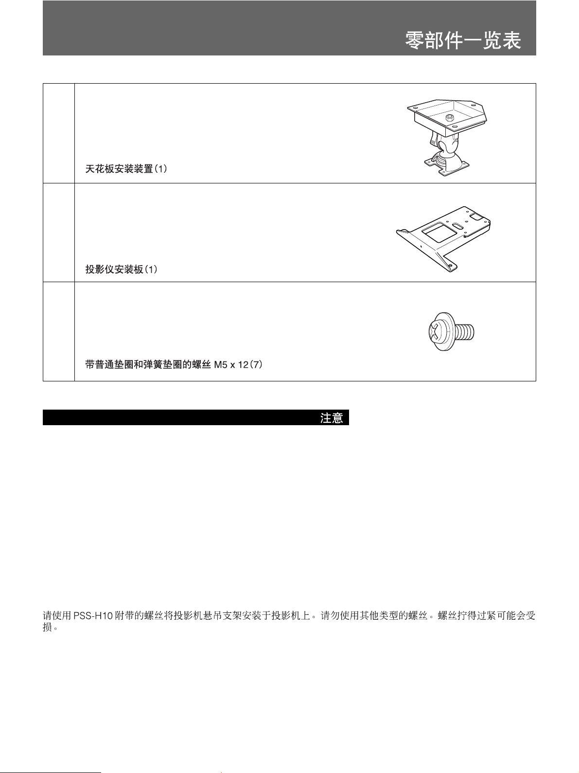
部品表/Parts List/Composants/Teileliste/Lista de
componentes/Elenco dei componenti/
(a)
(b)
(c)
天井つりユニット
Ceiling mount unit (1)
Dispositif de montage au plafond (1)
Deckenmontagevorrichtung (1)
Unidad de montaje en el techo (1)
Unità per l’installazione al soffitto (1)
プロジェクターマウントプレート
Projector mount plate (1)
Plaque de montage du projecteur (1)
Projektormontageplatte (1)
Placa de montaje del proyector (1)
Staffa di montaggio del proiettore (1)
平/バネ座金付きネジ M5×
Screw with plain washer and spring washer M5 x 12 (7)
Serrez la vis avec une rondelle plate et une rondelle frein M5 x 12 (7)
Schraube mit einfacher M5 x 12-Unterlegscheibe und -Federscheibe (7)
Tornillo con arandela plana y arandela elástica M5 x 12 (7)
Vite M5 x 12 con rondella semplice e rondella elastica (7)
(1)
(1)
12 (7)
ご注意 / Note / Remarque / Nota / Hinweis / Nota /
プロジェクターサスペンションサポートPSS-H10をプロジェクターに取り付ける際は本機に付属のネジを使用し、他のネジは使用し
ないでください。ネジを締めすぎた場合、プロジェクターの取り付け部分が破損することがあります。
Use the screws supplied with the PSS-H10 to install the projector suspension support on the projector. Do not use any other
type of screws. To tighten the screws too hard may cause damage.
Utilisez les vis fournies avec le PSS-H10 pour installer le support de suspension du projecteur sur le projecteur. N’utilisez
aucun autre type de vis. Ne vissez pas excessivement les vis. Vous pourriez endommager votre matériel.
Utilice los tornillos suministrados con el PSS-H10 para instalar el soporte de suspensión para proyector en éste. No utilice otro
tipo de tornillos. Si aprieta los tornillos con demasiada fuerza, pueden producirse daños.
Montieren Sie die Projektoraufhängung PSS-H10 mit den mitgelieferten Schrauben am Projektor. Verwenden Sie keine
anderen Schraubentypen. Wenn die Schrauben zu fest angezogen werden, kann es zu Schäden kommen.
Per l’installazione del supporto di sospensione sul proiettore, utilizzare le viti in dotazione con il modello PSS-H10. Non
utilizzare altri tipi di viti. Stringere eccessivamente le viti potrebbe causare danni.
6
Page 7

設置寸法/Installation Diagram/Schéma d’installation/ Installationsdiagramm/
Diagrama de instalación/
Schema dell’installazione/
スクリーンサイズと 投射距離の寸法および天井からプロジェクターまでの距離の寸法については、以下の説明書をご覧ください 。
-プロジェクター本体の取扱説明書
-レンズの取付説明書(別売りのレンズ使用時)
For details of screen size and installation measurement for projection and the distance between the ceiling and the
projector, refer to the following manuals.
- Operating Instructions of your projector
- Installation Manual of the projection lens (when using the optional lens)
Pour plus de détails sur le format d’écran, la distance de projection ainsi que la distance entre le plafond et le
projecteur, consultez les manuels ci-dessous :
- Mode d’emploi de votre projecteur
- Manuel d’installation de l’objectif (lors de l’utilisation de l’objectif optionnel)
Genaue Angaben zur Projektionsschirmgröße und zu den Installationsmaßen für die Projektion sowie zum
Abstand zwischen Decke und Projektor entnehmen Sie bitte den folgenden Handbüchern:
- Bedienungsanleitung zum Projektor
- Installationshandbuch zum Objektiv (bei Verwendung des gesondert erhältlichen Objektivs)
Para obtener información detallada sobre las medidas de instalación y el tamaño de la pantalla para la proyección y
sobre la distancia entre el techo y el proyector, consulte los siguientes manuales.
- Manual de instrucciones del proyector
- Manual de instalación del objetivo de proyección (al utilizar el objetivo opcional)
Per ulteriori informazioni sulle dimensioni dello schermo e sulle misure di installazione per la proiezione e sulla
distanza tra il proiettore e il soffitto, fare riferimento ai seguenti manuali.
- Istruzioni per l’uso del proiettore
- Manuale d’installazione dell’obiettivo (quando si utilizza l’obiettivo opzionale)
7
Page 8

天井への取り付けかた/Attaching to the Ceiling/ Montage au plafond/Montage an der Decke/
1
プロジェクター底面
Bottom of projector
Base du projecteur
Unterseite des Projektors
Base del proyector
Base del proiettore
B
(b)
A
(b)
(c)
(c)
2
スクリーン方向
Screen forward
Ecran ver l’avant
Projektionsschirm
Pantalla
Direzione dello
schermo
(a)
日本語
A レン ズ 側 にネジ 穴 が2つの場合
B レン ズ 側 にネジ 穴 が1つの場合
上記イラストAとBの取り付 け 作業上の違いはプロジェクターマ
ウントプレ ートの向きが180度 違うだけです。
1 プロジェクターを裏返し、プロジェクターマウントプ レ ート(b)
を取り付ける。
平/バネ座金付きネジ M5 ×12(c)(3 本)を使用します。
ご注意
• 取り付け の 際に、ネジをきつく締めすぎないように注意し
てください。
• プロジェクターや机に傷がつかないよう布などを敷いた
上で作業を行ってください。
2 天井つりユニット(a)を天井に取り付ける。
市販のM10ボルト、 ナット、ワッシ ャ ー を ご使用ください。
ご注意 ご注意
取り付けの向きに注意してください。
English
A: Two screw holes for the lens side
B: One screw hole for the lens side
The difference between A and B in the above figures is
that the projector mount plate direction is different (180°).
1 Turn the projector upside down and attach the
projector mount plate (b) using three screws with
plain washer and spring washer M5 × 12 (c).
Notes
•When attaching the projector mount plate, be
careful not to overtighten the screws.
• Before attaching the projector mount plate, place a
protective sheet (cloth) beneath the projector.
2 Attach the ceiling mount unit (a) to the ceiling.
Use M10 bolts, nuts and washers (not supplied).
Notes Notes
Be careful of the installation direction of the ceiling
mount unit.
8
Page 9

Montaje en el techo/Montaggio al soffitto/
Français
A: Deux trous de vis du côté de l’objectif
B: Un trou de vis du côté de l’objectif
La différence entre A et B dans les figures ci-dessus est que le
sens de montage de la plaque est différent (180 °).
1 Retournez le projecteur et fixez la plaque de montage du
projecteur (b) à l’aide de trois vis avec une rondelle plate
et une rondelle frein M5 × 12 (c).
Remarques
• Lors de l’installation de la plaque de montage du
projecteur, veillez à ne pas trop serrer les vis.
• Avant de fixer la plaque de montage du projecteur,
placez une protection (chiffon) sous le projecteur.
2 Fixez au plafond le dispositif de montage au plafond (a).
Utilisez des boulons M10, des écrous et des rondelles (non
fournis).
Remarques
Faites attention au sens d’installation du dispositif de
montage au plafond.
Español
A: Dos orificios de tornillo para el lateral del objetivo
B: Un orificio de tornillo para el lateral del objetivo
La diferencia entre A y B en las figuras anteriores es que la
dirección de la placa de montaje del proyector es diferente (180º).
1 Dé la vuelta al proyector y fije la placa de montaje del
proyector (b) mediante tres tornillos con arandela plana y
arandela elástica M5 × 12 (c).
Notas
• Al instalar la placa de montaje del proyector, tenga
cuidado de no apretar en exceso los tornillos.
• Antes de instalar la placa de montaje del proyector,
coloque una hoja protectora (paño) debajo del proyector.
2 Coloque la unidad de montaje en el techo (a) en el techo.
Utilice pernos M10, tuercas y arandelas (no
suministrados).
Nota
Preste atención a la dirección de la instalación de la unidad
de montaje en el techo.
Deutsch
A: Zwei Schraubenbohrungen auf der Objektivseite
B: Eine Schraubenbohrung auf der Objektivseite
Der Unterschied zwischen der Abbildung A und B oben liegt in
der unterschiedlichen Ausrichtung der Projektormontageplatte
(180°).
1 Drehen Sie den Projektor um und bringen Sie die
Projektormontageplatte (b) mit drei M5 × 12-Schrauben
und einfachen Unterlegscheiben und Federscheiben (c) an.
Hinweise
• Achten Sie beim Anbringen der Projektormontageplatte
darauf, die Schrauben nicht zu fest anzuziehen.
• Legen Sie vor dem Anbringen der
Projektormontageplatte zum Schutz ein Tuch o. ä. unter
den Projektor.
2 Bringen Sie die Deckenmontagevorrichtung (a) an der
Decke an.
Verwenden Sie M10-Schrauben, -Muttern und
–Unterlegscheiben (nicht mitgeliefert).
Hinweis
Achten Sie beim Installieren auf die Ausrichtung der
Deckenmontagevorrichtung.
Italiano
A: Due fori delle viti per la parte laterale dell’obiettivo
B: Un foro della vite per la parte laterale dell’obiettivo
La differenza tra A e B nelle figure sopra è la direzione della
staffa di montaggio del proiettore (180°).
1 Capovolgere il proiettore e applicare la relativa staffa di
montaggio (b) utilizzando tre viti M5 × 12 con rondella
semplice e rondella elastica (c).
Note
• Durante l’applicazione della staffa di montaggio,
assicurarsi di non serrare eccessivamente le viti.
• Prima di applicare la staffa di montaggio, sistemare un
foglio (panno) di protezione sotto il proiettore.
2 Applicare al soffitto l’apposita unità per l’installazione (a).
Utilizzare bulloni, dadi e rondelle di tipo M10 (non in
dotazione).
Nota
Prestare attenzione alla direzione in cui viene installata
l’unità per l’installazione al soffitto.
9
Page 10

天井への取り付けかた/Attaching to the ceiling/
Montage au plafond/Montage an der Decke/Montaje en el techo/
3
A
スクリーン方向
Screen forward
Ecran vers l’avant
Projektionsschirm
Pantalla
Direzione dello
schermo
B
スクリーン方向
Screen forward
Ecran vers l’avant
Projektionsschirm
Pantalla
Direzione dello
schermo
(a)
(a)
(b)
(b)
(2)
(2)
(3)
(3)
4
A
(c)
(1)
B
(c)
(1)
日本語
3 プロジェクターマウントプ レ ート(b)を天井つりユ ニット(a)に
仮どめする。
天井つりユニットの 仮固定用ネジ(1)をプロジェクターマウ
ントプレ ートのネジ 穴 に 差し込 み、確実に締め付けるため、
プロジェクターを手で上に押し上げながら仮固定用つまみ
(上)(2)を回して固定する。
さらに 仮固定用つまみ(下)(3)を回して締め付ける。
4 手順3で仮どめした天井つりユニットとプロジェクターマウ
ントプレ ートを固定する。
ネジ M 5 × 12(c)(4本)を使用します。
10
English
3 Temporarily attach the projector mount plate (b) to
the ceiling mount unit (a).
Insert the temporary fixing screw (1) on the ceiling
mount unit into the screw hole on the projector
mount plate, and while pushing the projector upward
with your hand, turn the upper temporary fixing
knob (2) to fix the projector mount plate securely.
Then turn the lower temporary fixing know (3) to
tighten the projector mount plate.
4 Secure the ceiling mount unit and the projector
mount plate you attached temporarily in step 3.
Use four M5 × 12 screws (c).
Page 11

Montaggio al soffitto/
Français
3 Fixez temporairement la plaque de montage du
projecteur (b) sur le dispositif de montage au
plafond (a).
Insérez la vis de fixation temporaire (1) du dispositif
de montage au plafond dans l’orifice prévu à cet
effet sur la plaque de montage du projecteur, puis
tournez le bouton de fixation temporaire supérieur
(2) tout en poussant le projecteur vers le haut avec
votre main, afin de fixer correctement la plaque de
montage du projecteur.
Tournez ensuite le bouton de fixation temporaire
inférieur (3) pour visser la plaque de montage du
projecteur.
4 Fixez correctement le dispositif de montage au
plafond et la plaque de montage du projecteur que
vous aviez fixés temporairement à l’étape 3.
Utilisez quatre vis M5 × 12 (c).
Español
Deutsch
3 Bringen Sie die Projektormontageplatte (b)
provisorisch an der Deckenmontagevorrichtung (a)
an.
Setzen Sie die Schraube (1) zur provisorischen
Befestigung an der Deckenmontagevorrichtung in
die Schraubenbohrung an der
Projektormontageplatte ein. Halten Sie den Projektor
mit der Hand nach oben gedrückt und drehen Sie
den oberen Fixierknopf (2), um die
Projektormontageplatte provisorisch sicher zu
befestigen.
Drehen Sie dann den unteren Fixierknopf (3), um die
Projektormontageplatte provisorisch zu fixieren.
4 Sichern Sie die Deckenmontagevorrichtung und die
Projektormontageplatte, die Sie in Schritt 3
provisorisch angebracht haben.
Verwenden Sie dazu vier M5 × 12-Schrauben (c).
Italiano
3 Instale temporalmente la placa de montaje del
proyector (b) en la unidad de montaje en el techo (a).
Inserte el tornillo de fijación temporal (1) de la
unidad de montaje en el techo en el orificio del
tornillo de la placa de montaje del proyector y,
mientras empuja el proyector hacia arriba con la
mano, gire el mando de fijación temporal superior
(2) para fijar la placa de montaje del proyector
firmemente.
A continuación, gire el mando de fijación temporal
inferior (3) para apretar la placa de montaje del
proyector.
4 Fije la unidad de montaje en el techo y la placa de
montaje del proyector que instaló temporalmente en
el paso 3.
Utilice cuatro tornillos M5 × 12 (c).
3 Applicare temporaneamente la staffa di montaggio
del proiettore (b) all’unità per l’installazione al
soffitto (a).
Inserire la vite di fissaggio temporaneo (1) dell’unità
per l’installazione al soffitto nell’apposito foro sulla
staffa di montaggio del proiettore, quindi, mentre il
proiettore viene spinto manualmente verso l’alto,
ruotare la manopola di fissaggio temporaneo
superiore (2) per fissare saldamente la staffa di
montaggio del proiettore.
Infine, ruotare la manopola di fissaggio temporaneo
inferiore (3) per stringere la staffa di montaggio del
proiettore.
4 Fissare l’unità per l’installazione al soffitto e la
staffa di montaggio del proiettore, applicate
temporaneamente al punto 3.
Utilizzare quattro viti M5 × 12 (c).
11
Page 12

天井への取り付け例/Installation Examples/Exemples d’installation au plafond/Installationsbeispiele/
以下はサスペンションサポートが天井に取り付けられたときの様子を示します。天井の材質によって補強方法は多少異なります。
ご注意
取り付ける前に天井の最大耐用荷重が120kg以上あることをお確かめください。
The following illustrations show the projector suspension support attached to the ceiling. Installation is different
depending on the material of ceiling.
Caution
Before installation, check that the maximum ceiling loading is in excess of 120 kg (264 lb 9 oz) .
Les illustrations suivantes représentent le support de suspension du projecteur fixé au plafond. L’installation
s’effectue différemment en fonction de la constitution du plafond.
Remarque
Vérifiez que la charge maximale du plafond est supérieure à 120 kg (264 lb 9 oz) avant l’installation.
In den folgenden Abbildungen ist dargestellt, wie die Projektoraufhängung an der Decke angebracht wird. Die
Installation unterscheidet sich je nach Material der Decke.
Hinweis
Überprüfen Sie vor der Installation, ob die maximale Belastbarkeit der Decke mindestens 120 kg beträgt.
Las siguientes ilustraciones muestran el soporte de suspensión para proyector fijado al techo. La instalación varía
en función del material del techo.
Nota
Compruebe la capacidad de carga máxima del techo sea superior a 120 kg (264 lb 9 oz) antes de realizar la
instalación.
Le seguenti illustrazioni mostrano il montaggio al soffitto del supporto di sospensione del proiettore. La procedura
di installazione varia a seconda del tipo di soffitto.
Attenzione
Prima di procedere con l’installazione, verificare che il peso massimo di portata del soffitto sia superiore a 120 kg.
12
Page 13

Ejemplos de instalación en el techo/Esempi di
installazione al soffitto/
板天井に取り付ける場合/For wooden ceiling/Pour un plafond en bois/Montage
an einer Holzdecke/Para techos de madera/Montaggio ad un soffitto in
legno/
平屋または最上階の場合/For-one-story house or uppermost floor/Pour une maison à un étage ou pour
l’étage supérieur/Decke eines einstöckigen Hauses oder des obersten Stockwerks/ Para casas de
una planta o para las plantas superiores/Montaggio in una casa a piano unico o all’ultimo piano/
キャビネット前面
Front of the cabinet
Avant du meuble
Vorderseite des Gehäuses
Parte frontal de la caja
Parte anteriore dell’apparecchio
150
(6)
75
(3)
支柱中心
Center of the supporting pole
Centre du pivot de support
Mitte des Ständers
Centro de la columna de soporte
Centro per l’asta di supporto
補強材/Reinforcing material/Matériau de renfort/
Verstärkungsmaterial/Material de refuerzo/
Materiale di rinforzo/
梁
(5×20 cm)
/Roof beam (5 × 20 cm (2” × 8”)) /
Poutre (5 × 20 cm) /Trägerbalken (5 × 20 cm) /
Viga del techo (5 × 20 cm) /Trave del soffitto
(5 × 20 cm) /
天井/Ceiling line/Niveau du plafond/Deckenlinie/
Línea de techo/Livello del soffitto/
ナットとワッシャーで締めた
M10
ボルト
/
M10 bolt with nut and washer/Boulon M10 avec
écrou et rondelle/M10-Schraube mit Mutter und
Unterlegscheibe/Perno M10 con tuerca y
arandela/Bullone M10 con dado e rondella/
天井つりユニット
Ceiling mount unit
Dispositif de montage au plafond
Deckenmontagevorrichtung
Unidad de montaje en el techo
Unità per l’installazione al soffitto
レンズ中心
Center of the lens
Centre de I’objectif
Mitte des Objektivs
Centro del objetivo
Centro della lente
くぎ
Nail
Clou
130
(5
Nagel
1
/8)
Punta
Chiodo
単位
: mm
Units : mm (inches)
Unité : mm (pouces)
Einheit : mm
Unidades : mm (pulgadas)
Unità : mm
支柱中心からレンズ中心までの距離は機種によって異なりますので、プロジェクター本体の特約店様用設置説明書をご覧ください。
*
機種によってはプロジェクターマウントプレートが逆方向に装着されます。
*
* The distance between the center of the supporting pole and the center of the lens differs depending on the model. For details, refer to the Installation Manual for Dealers.
*In some models, the projector mount plate will be installed in the opposite direction.
* La distance entre l’axe du pivot de support et l’axe de l’objectif diffère suivant les modèles. Pour plus de détails, reportez-vous au manuel d’installation destiné aux revendeurs.
* Sur certains modèles, la plaque de montage du projecteur est installée dans l’autre sens.
*
Der Abstand zwischen der Mitte des Ständers und der Mitte des Objektivs hängt vom jeweiligen Modell ab. Einzelheiten dazu finden Sie in der
Installationsanleitung für Händler.
*
Bei einigen Modellen wird die Projektormontageplatte in umgekehrter Richtung installiert.
*
La distancia entre el centro del polo de apoyo y el centro del objetivo varía en función del modelo. Para obtener información detallada, consulte el manual de
instalación para proveedores.
*
En determinados modelos, la placa de montaje del proyector se instala en la dirección contraria.
*
La distanza tra il centro dell’asta di supporto e il centro dell’obiettivo cambia in base al modello. Per ulteriori informazioni, fare riferimento al manuale di
installazione per i rivenditori.
*
In alcuni modelli, la staffa di montaggio del proiettore viene installata nella direzione opposta.
13
Page 14

天井への取り付け例/Installation Examples/Exemples d’installation
au plafond/Installationsbeispiele/
その他の階の場合/For other floors/Autres sols/Zwischendecken/Para otros suelos/Per altri piani/
キャビネット前面
Front of the cabinet
Avant du meuble
Vorderseite des Gehäuses
Parte frontal de la caja
Parte anteriore dell’apparecchio
上の階の床/Floor line/Niveau du plancher/
Bodenlinie/Línea de suelo/Livello del pavimento/
150
(6)
75
(3)
支柱中心
Center of the supporting pole
Centre du pivot de support
Mitte des Ständers
Centro de la columna de soporte
Centro per l’asta di supporto
梁
(5×20 cm)
/Joist (5 × 20 cm (2” × 8”)) /Traverse
(5 × 20 cm) /Deckenbalken (5 × 20 cm) /Traviesa
(5 × 20 cm) /Travetto (5 × 20 cm) /
梁
(5×20 cm)
/Roof beam (5 × 20 cm (2” × 8”)) /
Poutre (5 × 20 cm) /Trägerbalken (5 × 20 cm) /
Viga de techo (5 × 20 cm) /Trave del soffitto
(5 × 20 cm) /
天井/Ceiling line/Niveau du plafond/Deckenlinie/
Línea de techo/Livello del soffitto/
ナットとワッシャーで締めた
M10
ボルト
M10 bolt
/
with nut and washer/Boulon M10 avec écrou et
rondelle/M10-Schraube mit Mutter und
Unterlegscheibe/Perno M10 con tuerca y
arandela/Bullone M10 con dado e rondella/
天井つりユニット
Ceiling mount unit
Dispositif de montage au plafond
Deckenmontagevorrichtung
Unidad de montaje en el techo
Unità per l’installazione al soffitto
レンズ中心
Center of the lens
Centre de I’objectif
Mitte des Objektivs
Centro del objetivo
Centro della lente
130
1
(5
/8)
単位
: mm
Units : mm (inches)
Unité : mm (pouces)
Einheit : mm
Unidades : mm (pulgadas)
Unità : mm
支柱中心からレンズ中心までの距離は機種によって異なりますので、プロジェクター本体の特約店様用設置説明書をご覧ください。
*
機種によってはプロジェクターマウントプレートが逆方向に装着されます。
*
*
The distance between the center of the supporting pole and the center of the lens differs depending on the model. For details, refer to the Installation Manual for Dealers.
* In some models, the projector mount plate will be installed in the opposite direction.
*
La distance entre l’axe du pivot de support et l’axe de l’objectif diffère suivant les modèles. Pour plus de détails, reportez-vous au manuel d’installation destiné aux revendeurs.
* Sur certains modèles, la plaque de montage du projecteur est installée dans l’autre sens.
* Der Abstand zwischen der Mitte des Ständers und der Mitte des Objektivs hängt vom jeweiligen Modell ab. Einzelheiten dazu finden Sie in der
Installationsanleitung für Händler.
* Bei einigen Modellen wird die Projektormontageplatte in umgekehrter Richtung installiert.
* La distancia entre el centro del polo de apoyo y el centro del objetivo varía en función del modelo. Para obtener información detallada, consulte el manual de
instalación para proveedores.
* En determinados modelos, la placa de montaje del proyector se instala en la dirección contraria.
* La distanza tra il centro dell’asta di supporto e il centro dell’obiettivo cambia in base al modello. Per ulteriori informazioni, fare riferimento al manuale di
installazione per i rivenditori.
* In alcuni modelli, la staffa di montaggio del proiettore viene installata nella direzione opposta.
14
Page 15

Ejemplos de instalación en el techo/Esempi di installazione al
soffitto/
コンクリート天井に取り付ける場合/For concrete ceiling/Pour un plafond en
béton/Betondecke/Para techos de hormigón/Montaggio ad un soffitto di
cemento/
コンクリート天井/Concrete ceiling/
Plafond en béton/Betondecke/Techo de
hormigón/Soffitto di cemento/
壁端から
てください。
Place bolts at least 80 mm (3
1
/4 inches) away from wall. /
Ecartez les boulons de 80
1
mm (3
minimum. /Schrauben
mindestens 80 mm von der
Wand entfernt anbringen. /
Coloque los pernos a una
distancia de al menos 80 mm
1
/4 pulgadas)
(3
Collocare i bulloni ad almeno
/
80 mm dal muro. /
以上距離をとっ
80 mm
/4 pouces) du mur
de la pared.
プロジェクター
Projector
Projecteur
Projektor
Proyector
Proiettore
コンクリートアンカー
Anchor for concrete (over 12 mm;
dia.) / Ancrage pour béton (supérieur à
12 mm; 1/2 pouce de diamètre) /
Betonanker (mehr als 12 mm
Durchmesser) /Anclaje para hormigón
(con diámetro superior a 12 mm;
pulgada) /Catena per cemento (oltre 12
mm di diametro)/
天井つりユニット
Ceiling mount unit
Dispositif de montage au plafond
Deckenmontagevorrichtung
Unidad de montaje en el techo
Unità per l’installazione al soffitto
(12 mm
径以上
/
)
1
/2 inch
1
/2
15
Page 16

角度を調整する/Adjusting the Angle of the Projector/Réglage de l’angle du projecteur/Anpassen des Projektorwinkels/Ajuste del ángulo del proyector/Regolazione dell’angolazione del proiettore/
(2)
日本語
つまみ(e)を反時計方向(1)に回して充分にゆるませ、プロジェク
ターの 左 右 、水平、上下方向の角度を調整します。調整が終わっ
たら、つまみ(e)を時計方向(2)に回して固定します。
ご注意
調整可能な角度は、プロジェクターにより異なります。プロジェク
ター本体の取扱説明書をご覧ください。
Français
Tournez le bouton (e) dans le sens anti-horaire (1)
pour le desserrer et ajustez l’angle du projecteur
horizontalement et verticalement. Après le réglage,
tournez le bouton (e) dans le sens horaire (2) pour le
visser.
Remarque
L’angle de réglage varie d’un projecteur à l’autre.
Reportez-vous au mode d’emploi du projecteur.
Español
Gire el mando (e) hacia la izquierda (1) para aflojarlo
y ajuste el ángulo del proyector horizontal y
verticalmente. Una vez ajustado, gire el mando (e)
hacia la derecha (2) para apretarlo.
Nota
El ángulo ajustable varía en función del proyector.
Consulte el manual de instrucciones del proyector.
(1)
(e)
English
Turn the knob (e) counterclockwise (1) to loose it,
and adjust the angle of the projector horizontally and
vertically. After adjusting, turn the knob (e)
clockwise (2) to tighten it.
Note
The adjustable angle differs depending on the
projector. Refer to the Operating Instructions of the
projector.
Deutsch
Drehen Sie den Knopf (e) zum Lösen gegen den
Uhrzeigersinn (1) und stellen Sie den Winkel des
Projektors horizontal und vertikal ein. Drehen Sie
danach den Knopf (e) zum Anziehen im
Uhrzeigersinn (2).
Hinweis
Welcher Winkel eingestellt werden kann, hängt vom
Projektor ab. Informationen dazu finden Sie in der
Bedienungsanleitung zum Projektor.
Italiano
Ruotare la manopola (e) in senso antiorario (1) per
allentarla e regolare l’angolazione del proiettore
orizzontalmente e verticalmente. Dopo avere
completato la regolazione, ruotare la manopola (e) in
senso orario (2) per stringerla.
Nota
L’angolazione regolabile varia in base al tipo di
proiettore in uso. Consultare le istruzioni per l’uso del
proiettore.
16
Page 17

主な仕様
/Specifications/Spécifications/Technische
Daten/Especificaciones/Caratteristiche tecniche/
組み上げ時の寸法/Dimensions of the assembled bracket/Dimensions du support assemblé/
Abmessungen de montierten Halterung/Dimensiones del soporte de montaje/Dimensioni della staffa
montata/
上から見た図/Top view/Vue du dessus/Draufsicht/Vista superior/Vista dall’alto/
150.6 (6)
7
/16)
35 (1
13
/16) 85 (3 3/8)
45 (1
)
8
/
5
)
32
/
11
)
2
/
1
89.5 (3
8 (
75 (3)
188 (7
73.5 (3)
前から見た図/Front view/Vue frontale/Vorderansicht/Vista frontal/Vista frontale/
180 (7 1/8)
)
16
/
3
29.5
(1
)
8
/
5
115.5 (4
)
16
/
3
30
(1
8 (11/32)
1
188 (7
/2)
75 (3)
175 (7)
単位
Units : mm (inches)/Unité : mm (pouces)/Einheit : mm (Zoll)/
: mm/
Unidades : mm (pulgadas)/Unità : mm (pollici)/
17
Page 18

主な仕様
/Specifications/Spécifications/Technische Daten/
Especificaciones/Caratteristiche tecniche/
横から見た図/Side view/Vue de côté/Seitenansicht/Vista lateral/Vista laterale/
160 (6 3/8)
176 (7)
222.3 (7
1
/2)
単位
Unidades : mm (pulgadas)/Unità : mm (pollici)/
質量 約
Units : mm (inches)/Unité : mm (pouces)/Einheit : mm (Zoll)/
: mm/
2.5 kg
/Mass: Approx. 2.5 kg (5 lb 8 oz) /Poids : 2,5 kg approx. (5 lb 8 oz) /Gewicht: ca. 2,5 kg/
Masa: 2,5 kg aprox. (5 lb 8 oz) /Peso approssimativo: 2,5 kg/
耐用荷重 最大
20 kg
/Maximum loading: 20 kg (44 lb 2 oz) /Charge maximale : 20 kg (44 lb 2 oz) /
Maximale Belastbarkeit: 20 kg/Carga máxima: 20 kg/Carico massimo: 20 kg (44 lb 2 oz) /Portata
massima: 20 kg/
仕様および外観は、 改良のため予告なく変更することがありますが、 ご了承ください。
Design and specifications are subject to change without notice.
La conception et les spécifications sont sujettes à modifications sans préavis.
Änderungen, die dem technischen Fortschritt dienen, bleiben vorbehalten.
El diseño y las especificaciones están sujetos a cambios sin previo aviso.
Il design e le caratteristiche tecniche sono soggetti a modifiche senza preavviso.
18
Page 19

19
Page 20

商品の修理、お取扱い方法、お買い物相談などの問い合わせ
ホームページ ●
「ソニードライブ」は、ソニーの商品情報とライフスタイルをご提案するホームページです。
「良くあるご質問」「修理情報」「ショッピング情報」は、ホームページをご活用ください。
http://www.sony.co.jp/SonyDrive/
お客様ご相談センター
● ナビダイヤル*........................................ 0570-00-3311
(全国どこからでも市内通話でご利用いただけます)
●
携帯電話・PHSでのご利用は*........................ 03-5448-3311
(ナビダイヤルがご利用できない場合はこちらをご利用ください)
●FAX .................................................................. 0466-31-2595
受付時間:月〜金曜日9:00〜20:00 土・日・祝 日 9:00〜17:00
*
お電話は自動音声応答にてお受けし、内容に応じて専門の相談員が対応します。
はじめにご用件を下記より、次に音声案内にそって商品カテゴリーの番号を押してください。
選択番号は変更になることがありますので、ご容赦願います。
1:修理受付
2:使用方法や故障と思われるご相談
3:お買物相談
4:業務用・プロ用商品に関するご相談全般
5:その他のご相談
ソニー株式会社 〒141-0001 東京都品川区北品川6-7-35
6-7-35 Kitashinagawa, Shinagawa-ku, Tokyo, JAPAN 141-0001
この説明書は 100% 古紙再生紙を使用しています。
Printed on 100 % recycled paper.
Sony Corporation Printed in Japan
 Loading...