

Sony PSS-70 User Manual
3-859-049-02(1)
Projector
Suspension Support
プロジェクターサスペンションサポート
特約店様用取付説明書
お買い上げいただきありがとうございます。
お客様へ
この取付説明書は、特約店様用に書かれたものです。
警告
お客様が取付説明書に記載された取付工事を行うと、事故などにより死亡や大けがにつな
がることがあります。お客様自身では絶対に取付工事をしないでください。取り付けにつ
いては必ずお買い上げ店またはソニーのサービス窓口にご依頼ください。
特約店の方は、取り付けを安全に行うために、必ずこの説明書をよくお読みください。
Installation manual for Dealers
Manuel d’installation destiné aux revendeurs
Installationshandbuch für Händler
Manual de instalación para proveedores
Manuale d’installazione per i rivenditori
CCCCCC
PSS-70
1996 by Sony Corporation
日本語
English
耐用荷重:最大
PSS-70はソニーのマルチスキャンプロジェクターの天井吊り下げ
用サスペンションサポートです。
120 kg
安全のために
下記の注意事項を守らないと、死亡や
警告
製品の落下による死亡、大けがなどの事
故を避けるため、下記の注意事項を必ず
お守りください。
・設置は、ソニーサービス窓口またはお買い上げ店にご依頼ください。
・天井は少なくとも
じて補強を行ってください。
・ブラケットを天井に直接取り付ける場合には、天井に合わせて、
市販の
以外のボルト、ナット、ワッシャーで取り付けると落下する危険
があります。
・取り付けは手順に従ってください。手順に従わないと落下する危
険や、死亡・大けがになることがあります。
・
PSS-70
下げ用サスペンションサポートです。それ以外の用途には使用
しないでください。
ボルトとナット、ワッシャーをご使用ください。
M10
はソニーのマルチスキャンプロジェクターの天井吊り
大けがになることがあります。
の重量を支えられるように、必要に応
650 kg
M10
Maximum load: 120 kg (264 lb 9 oz)
The PSS-70 suspension support is designed for use
with Sony Multiscan projector.
Caution
• For installation, consult with qualified Sony
personnel.
• The ceiling should be capable of supporting a
weight of at least 650 kg (1410 lb 15 oz); if not,
the ceiling must be reinforced.
• When you attach the bracket directly to the
ceiling, use commercially available M10 bolts
with nuts and washers, depending on the
ceiling. Use of other bolts, nuts, and washers
other than M10 may present a danger of falling.
• Be sure to assemble and attach the bracket in
the order indicated; otherwise the projector may
fall, resulting in grievous bodily injury or even
death.
• The PSS-70 suspension support is designed for
use with Sony Multiscan projctor. Never use it
for another purpose.
Deutsch
Français
Charge maximale: 120 kg (264 lb 9 oz)
Le support de suspension PSS-70 est conçu pour être
utilisé avec un projecteur Multiscan Sony.
Attention
• Pour l’installation, adressez-vous à un personnel
Sony qualifié.
• Le plafond doit pouvoir supporter un poids d’au
moins 650 kg (1410 lb 15 on) ; dans le cas
contraire, il y a lieu de renforcer le plafond.
• Lorsque vous attachez le support directement au
plafond, utilisez des boulons M10 disponibles
dans le commerce avec les écrous et rondelles, en
fonction du plafond. L’utilisation de boulons,
écrous et rondelles différents peut représenter un
danger de chute auquel cas vous courez un risque
de blessure voire un danger de mort.
• Assemblez et fixez le support dans l’ordre
indiqué; sinon, le projecteur risque de tomber
auquel cas vous courez un risque de blessure
voire un danger de mort.
• Le support de suspension PSS-70 est conçu pour
être utilisé avec un projecteur Multiscan Sony. Ne
l’utilisez jamais à d’autres fins.
2
Maximale Belastbarkeit: 120 kg
Die Aufhängung PSS-70 wurde speziell für
Multiscan-Projektoren von Sony konzipiert.
Vorsicht
• Wenden Sie sich bei der Installation an
qualifizierte Fachkräfte von Sony.
• Die Decke sollte für eine Tragfähigkeit von
mindestens 650 kg ausgelegt ist. Andernfalls muß
die Decke verstärkt werden.
• Wenn Sie die Halterung direkt an der Decke
befestigen, verwenden Sie handelsübliche M10Schrauben mit Muttern und Unterlegscheiben (je
nach Decke). Wenn Sie keine M10-Schrauben, Muttern und -Unterlegscheiben verwenden,
besteht die Gefahr, daß das Gerät herunterfällt.
• Achten Sie darauf, die Halterung in der
angegebenen Reihenfolge zu montieren und
anzubringen. Andernfalls kann der Projektor
herunterfallen. Dabei könnte es zu schweren
Unfällen kommen!
• Die Aufhängung PSS-70 wurde speziell für
Multiscan-Projektoren von Sony konzipiert.
Verwenden Sie sie ausschließlich für diese
Projektoren.
Español
Italiano
Carga máxima: 120 kg (264 lb 9 oz)
El soporte de suspensión PSS-70 está diseñado para
utilizarse con el proyector Sony Multiscan.
Precaución
• Para realizar la instalación, consulte con personal
Sony especializado.
• El techo debe ser capaz de soportar un peso de al
menos 650 kg (1410 lb 15 oz). De no ser así, es
necesario reforzarlo.
• Al fijar el soporte directamente en el techo, utilice
pernos M10, disponibles en las tiendas del ramo,
con tuercas y arandelas en función del techo. El
uso de pernos, tuercas y arandelas que no sean
M10 puede presentar peligro de caída.
• Asegúrese de montar y fijar el soporte en el orden
indicado, ya que en caso contrario es posible que
el proyector se caiga, y puede existir riesgo de
lesiones graves o fallecimiento.
• El soporte de suspensión PSS-70 está diseñado
para utilizarse con el proyector Sony Multiscan.
No lo utilice para ningún otro propósito.
Portata massima: 120 kg
Il supporto di sospensione PSS-70 è stato progettato
per essere utilizzato con il proiettore Sony Multiscan.
Attenzione
• Per l’installazione, consultare personale
qualificato Sony.
• Il soffitto deve essere in grado di sopportare un
peso di almeno 650 kg. Altrimenti il soffitto
dovrà essere rinforzato.
• Per l’applicazione della staffa direttamente al
soffitto, utilizzare bulloni, dadi e rondelle di
tipo M10, comunemente disponibili in
commercio, in funzione del soffitto. L’uso di
altri tipi di bulloni, dadi e rondelle potrebbe
rappresentare un pericolo di caduta.
• Assicurarsi di montare ed applicare la staffa
seguendo l’ordine indicato. Diversamente il
proiettore potrebbe cadere si potrebbero correre
grossi rischi.
• Il supporto di sospensione PSS-70 è stato
progettato per essere utilizzato con il proiettore
Sony Multiscan. Non utilizzarlo per altri scopi.
CCCCCC
3

目次/Table of contents/Table des matières/Inhalt/
Indice/Indice/CCCCC
部品表.......................................................................................
天井への取り付けかた............................................................
天井への取り付け例..............................................................
主な仕様.................................................................................
Parts List ................................................................... 5
Attaching to the ceiling .............................................. 7
Installation examples............................................... 17
Specifications .......................................................... 21
Composants .............................................................. 5
Montage au plafond................................................... 7
Examples d’installation au plafond ..........................17
Spécifications .......................................................... 21
Teileliste .................................................................... 5
Montage an der Decke ..............................................7
Installationsbeispiele ............................................... 17
Technische Daten ................................................... 21
17
21
5
7
Lista de componentes ............................................... 5
Montaje en el techo ................................................... 7
Ejemplos de instalación en el techo ........................ 17
Especificaciones...................................................... 21
Elenco dei componenti .............................................. 5
Montaggio al soffitto .................................................. 7
Esempi di installazione al soffitto............................. 17
Caratteristiche tecniche........................................... 21
CCCCCCCC
CCCCCCCCC
CCCCCCCC
CCCCCCC
4
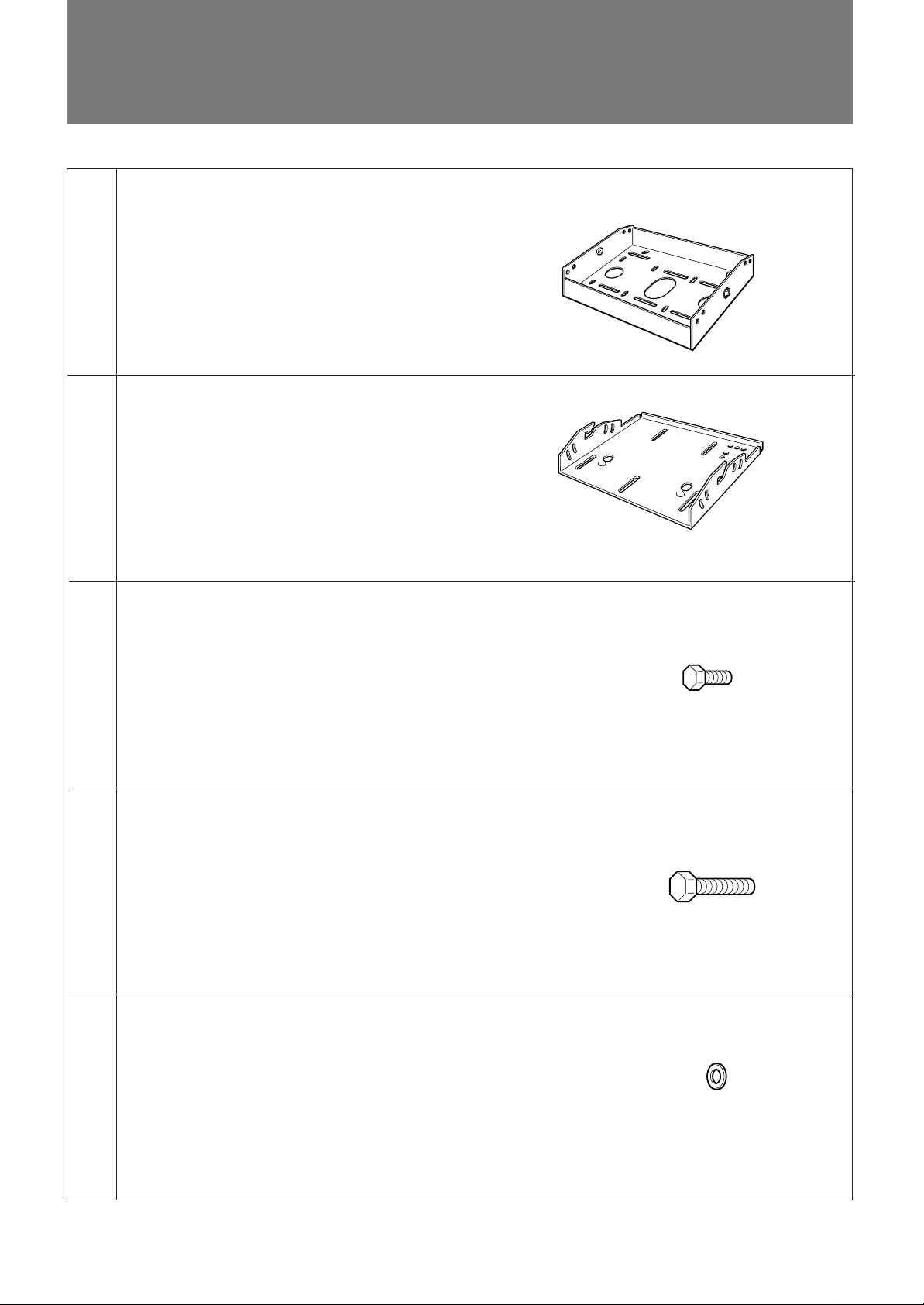
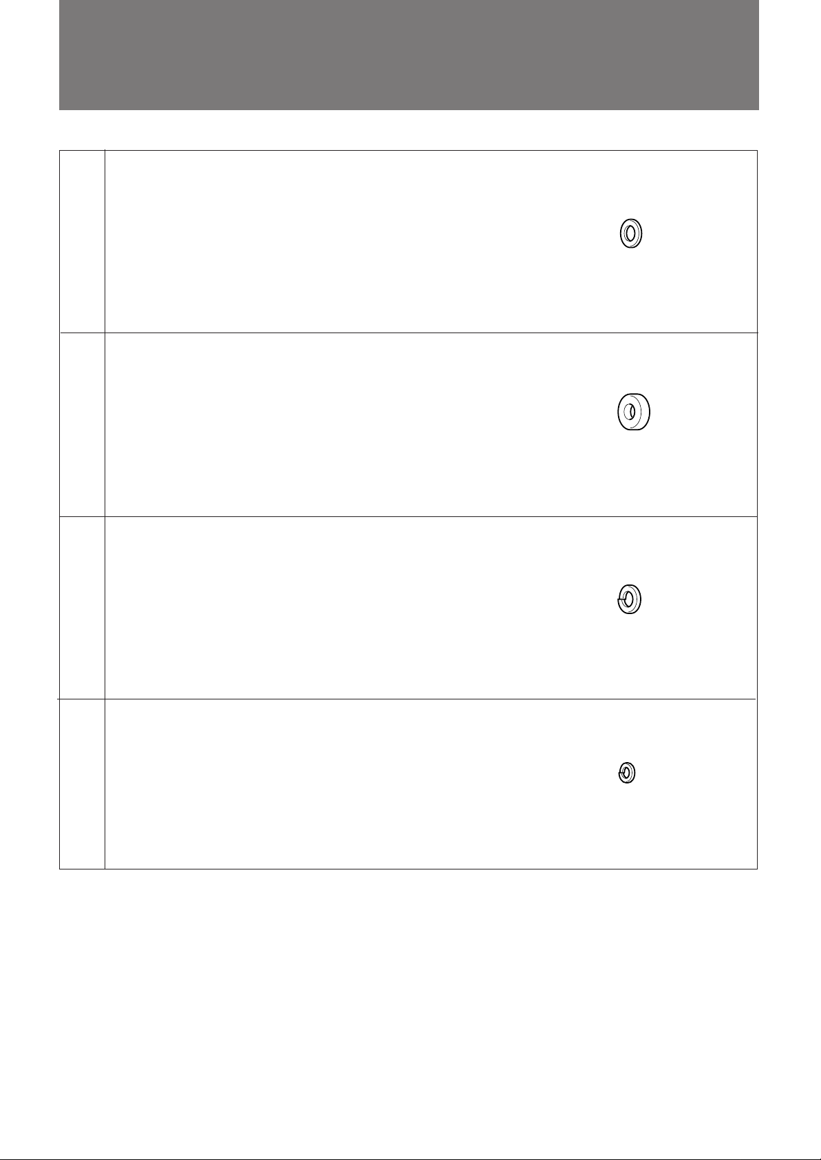
部品表/Parts List/Composants/Teileliste/Lista de
componentes/Elenco dei componenti/CCCCC
天井用マウントブラケット(1)
Upper ceiling mount bracket (1)
Support supérieur de montage pour plafond (1)
Obere Deckenmontagehalterung (1)
(a)
(b)
Soporte superior de montaje para techo (1)
Staffa superiore di montaggio al soffitto (1)
CCCCC
プロジェクターマウントブラケット(1)
Projector mount bracket (1)
Support de montage du projecteur (1)
Projektormontagehalterung (1)
Soporte de montaje de proyector (1)
Staffa di montaggio del proiettore (1)
CCCCCCC
(c)
(d)
(e)
ボルトM6×12(4)
Bolt M6 × 12 (4)
Boulon M6 × 12 (4)
Schraube M6 × 12 (4)
Perno M6 × 12 (4)
Bullone M6 × 12 (4)
CCCCCC
ボルトM8×20(7)
Bolt M8 × 20 (7)
Boulon M8 × 20 (7)
Schraube M8 × 20 (7)
Perno M8 × 20 (7)
Bullone M8 × 20 (7)
CCCCCCC
ワッシャーM6用(4)
Washer M6 (4)
Rondelle M6 (4)
Unterlegscheibe M6 (4)
Arandela M6 (4)
Rondella M6 (4)
CCCCC
部品番号/Parts number
Référence de pièce
Teilenummer
Número de piezas
Numero dei componenti
CCCC
4-056-754-01
部品番号/Parts number
Référence de pièce
Teilenummer
Número de piezas
Numero dei componenti
CCCC
4-047-766-01
部品番号/Parts number
Référence de pièce
Teilenummer
Número de piezas
Numero dei componenti
CCCC
4-056-755-01
5
部品表/Parts List/Composants/Teileliste/Lista de componentes/
Elenco dei componenti/CCCCC
(f)
(g)
(h)
ワッシャーM8用(7)
Washer M8 (7)
Rondelle M8 (7)
Unterlegscheibe M8 (7)
Arandela M8 (7)
Rondella M8 (7)
CCCCC
スペーサー(2)
Spacer (2)
Entretoise (2)
Abstandsring (2)
Espaciadore (2)
Distanziatore (2)
CCCCC
スプリングワッシャーM8用(7)
Spring washer M8 (7)
Rondelle frein M8 (7)
Federscheibe M8 (7)
Arandela de resorte M8 (7)
Rondella a molla M8 (7)
CCCCCC
部品番号/Parts number
Référence de pièce
Teilenummer
Número de piezas
Numero dei componenti
CCCC
4-047-748-01
部品番号/Parts number
Référence de pièce
Teilenummer
Número de piezas
Numero dei componenti
CCCC
4-056-753-01
部品番号/Parts number
Référence de pièce
Teilenummer
Número de piezas
Numero dei componenti
CCCC
4-047-749-01
部品番号/Parts number
Référence de pièce
Teilenummer
Número de piezas
Numero dei componenti
CCCC
4-055-230-01
(i)
スプリングワッシャーM6用(4)
Spring washer M6 (4)
Rondelle frein M6 (4)
Federscheibe M6 (4)
Arandela de resorte M6 (4)
Rondella a molla M6 (4)
CCCCCC
6
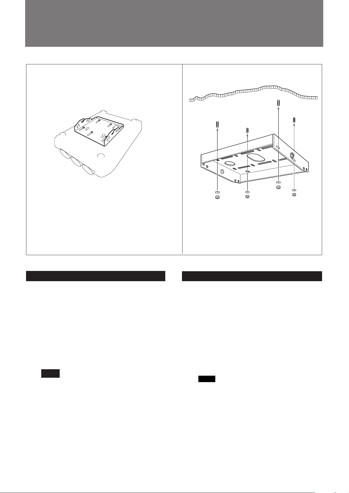
天井への取り付けかた/Attaching to the ceiling/
Montage au plafond/Montage an der Decke/
1
2
(b)
(a)
プロジェクター底面
Bottom of projector
Base du projecteur
Unterseite des Projektors
Base del proyector
Base del proiettore
CCCCC
日本語
1 プロ ジェ クターマ ウ ントブラケット(b)をプロジェ ク ターに取
り付ける。
ボルトM8×20(d)、ワッシャーM8用(f)、スプリングワ ッ
シャーM8用(h) を使用します。(5か所)
プロジェクターへ の 取り付け か たは、 取り付けるプロジェク
ターの設置説明書をご覧ください。
2 天井用マウントブラケッ ト (a) を天井に取り付け る。
市販のM10ボルト、ナット、ワッシャーをご使用ください。
ご注意
スクリーンに対する天井用マウントブラケッ ト(a) の向きに
ついては、「角度を調整するには」(13〜14ページ)をご覧
ください。
English
1 Attach the projector mount bracket (b) to the
projector.
Use five bolts M8×20 (d), washers M8 (f) and spring
washers M8 (h).
To attach the projector mount bracket to the
projector, refer to the “Installation Manual” of the
projector to be attached.
2 Attach the upper ceiling mount bracket (a) to the
ceiling.
Use M10 bolts, nuts and washers (all commercially
available).
Note
The direction of the upper ceilling mount bracket (a)
facing a screen, refer to “Adjusting the Angle of the
Projector” on pages 13-14.
7
Montaje en el techo/Montaggio al soffitto/CCCCC
Français
1 Fixez le support de montage du projecteur (b) sur le
projecteur. Utilisez les boulons M8×20 (d), les
rondelles M8 (f) et les rondelles frein M8 (h).
Pour fixer le support de montage du projecteur sur le
projecteur, reportez-vous au “Manuel d’installation”
du projecteur à installer.
2 Fixez le support supérieur de montage pour plafond
(a) au plafond. Utilisez les boulons M10, les écrous
et les rondelles (tous disponibles dans le commerce).
Remarque
Pour régler le sens du support supérieur de montage
pour plafond (a) face à un écran, reportez-vous à la
section “Réglage de l’angle du projecteur” aux
pages 13-14.
Español
1 Fije el soporte de montaje de proyector (b) a éste.
Emplee pernos M8×20 (d), arandelas M8 (f) y
arandelas resorte M8 (h).
Para ajustar el soporte de montaje al proyector,
consulte el “Manual de instalación” del proyector
correspondiente.
2 Fije al techo el soporte superior de montaje para
techo (a).
Emplee arandelas, tuercas y pernos M10 (todos
disponibles en las tiendas del ramo).
Nota
Para conocer la dirección del soporte de montaje
superior para techo (a) orientado a una pantalla,
consulte “Ajuste de ángulo del proyector” en las
páginas 13-14.
CCCCC
Deutsch
1 Bringen Sie die Projektormontagehalterung (b) an
den Projektor an.
Verwenden Sie dazu M8×20-Schrauben (d), M8Unterlegscheiben (f) und M8-Federscheiben (h).
Wie Sie die Projektormontagehalterung am
Projektor anbringen, schlagen Sie bitte in der
Installationsanleitung des zu montierenden
Projektors nach.
2 Bringen Sie die Deckenmontagehalterung (a) mit
M10-Schrauben, -Muttern und -Unterlegscheiben
(alle handelsüblich) an der Decke an.
Hinweis
In welcher Richtung die Deckenmontagehalterung
(a) auf den Projektionsschirm weisen muß, erfahren
Sie unter “Anpassen des Projektorwinkels” auf Seite
13-14.
Italiano
1 Fissare la staffa di montaggio del proiettore (b) al
proiettore.
Usare bulloni M8×20 (d), rondelle M8 (f) e
rondelle a molla M8 (h).
Per collegare la staffa di supporto al proiettore, fare
riferimento al manuale di installazione del proiettore
da collegare.
2 Fissare la staffa superiore di montaggio al soffitto
(a) al soffitto.
Usare bulloni M10, dadi e rondelle (tutti disponibili
in commercio).
Nota
Per la direzione della staffa di montaggio al soffitto
(a) di fronte allo schermo, fare riferimento alla
sezione sulla regolazione dell’angolazione del
proiettore alle pagine 13-14.
8
 Loading...