

Page 1

Professional
4-488-667-11(1)
Video Monitor
Operating Instructions
Before operating the unit, please read this manual thoroughly
and retain it for future reference.
PVM-A250
PVM-A170
© 2013 Sony Corporation
Page 2
Owner’s Record
The model and serial numbers are located at the rear.
Record these numbers in the spaces provided below.
Refer to these numbers whenever you call upon your
Sony dealer regarding this product.
Model No.
Serial No.
Important Safety Instructions
Read these instructions.
Keep these instructions.
Heed all warnings.
Follow all instructions.
Do not use this apparatus near water.
Clean only with dry cloth.
Do not block any ventilation openings.
Install in accordance with the manufacturer’s
instructions.
Do not install near any heat sources such as radiators,
heat registers, stoves, or other apparatus (including
amplifiers) that produce heat.
Do not defeat the safety purpose of the polarized or
grounding-type plug. A polarized plug has two blades
with one wider than the other. A grounding-type plug
has two blades and a third grounding prong. The wide
blade or the third prong are provided for your safety.
If the provided plug does not fit into your outlet,
consult an electrician for replacement of the obsolete
outlet.
Protect the power cord from being walked on or
pinched particularly at plugs, convenience receptacles,
and the point where they exit from the apparatus.
Only use attachments/accessories specified by the
manufacturer.
Use only with the cart, stand, tripod,
bracket, or table specified by the
manufacturer, or sold with the apparatus.
When a cart is used, use caution when
moving the cart/apparatus combination to avoid
injury from tip-over.
Unplug this apparatus during lightning storms or
when unused for long periods of time.
Refer all servicing to qualified service personnel.
Servicing is required when the apparatus has been
damaged in any way, such as power-supply cord or
plug is damaged, liquid has been spilled or objects
have fallen into the apparatus, the apparatus has been
exposed to rain or moisture, does not operate
normally, or has been dropped.
WARNING
To reduce the risk of fire or electric shock, do not
expose this apparatus to rain or moisture.
To avoid electrical shock, do not open the cabinet.
Refer servicing to qualified personnel only.
THIS APPARATUS MUST BE EARTHED.
WAR NIN G
When installing the unit, incorporate a readily accessible
disconnect device in the fixed wiring, or connect the
power plug to an easily accessible socket-outlet near the
unit. If a fault should occur during operation of the unit,
operate the disconnect device to switch the power supply
off, or disconnect the power plug.
CAUTION
This Professional Video Monitor should only be used
with a specified monitor stand. For information on
suitable stands, refer to “Specifications.” Installation of
the Professional Video Monitor on any other stand may
result in instability, possibly leading to injury.
This symbol is intended to alert the user
to the presence of uninsulated “dangerous
voltage” within the product’s enclosure
that may be of sufficient magnitude to
constitute a risk of electric shock to
persons.
This symbol is intended to alert the user
to the presence of important operating
and maintenance (servicing) instructions
in the literature accompanying the
appliance.
Attention-when the product is installed in Rack:
(For PVM-A170)
1. Prevention against overloading of branch circuit
When this product is installed in a rack and is supplied
power from an outlet on the rack, please make sure that
the rack does not overload the supply circuit.
2. Providing protective earth
When this product is installed in a rack and is supplied
power from an outlet on the rack, please confirm that the
outlet is provided with a suitable protective earth
connection.
2
Page 3

3. Internal air ambient temperature of the rack
When this product is installed in a rack, please make
sure that the internal air ambient temperature of the rack
is within the specified limit of this product.
4. Prevention against achieving hazardous
condition due to uneven mechanical loading
When this product is installed in a rack, please make
sure that the rack does not achieve hazardous condition
due to uneven mechanical loading.
5. Install the equipment while taking the operating
temperature of the equipment into
consideration
For the operating temperature of the equipment, refer to
the specifications of the Operation Manual.
6. When performing the installation, keep the
following space away from walls in order to
obtain proper exhaust and radiation of heat.
Lower, Upper: 4.4 cm (1 3/4 inches) or more
Right, Left: 1.0 cm (3/8 inches) or more
For PVM-A250
When installing the installation space must be secured
in consideration of the ventilation and service operation.
Do not block the ventilation slots at the rear panel, and
vents of the fans.
Leave a space around the unit for ventilation.
Leave more than 40 cm of space in the rear of the unit
to secure the operation area.
When the unit is installed on the desk or the like, leave at
least 1U (4.4 cm) or more of space above and below the
unit. Leaving 40 cm or more of space above the unit is
recommended for service operation.
CAUTION
The apparatus shall not be exposed to dripping or
splashing. No objects filled with liquids, such as vases,
shall be placed on the apparatus.
CAUTION
The unit is not disconnected from the AC power source
(mains) as long as it is connected to the wall outlet, even
if the unit itself has been turned off.
WAR NIN G
Excessive sound pressure from earphones and
headphones can cause hearing loss.
In order to use this product safely, avoid prolonged
listening at excessive sound pressure levels.
WARNING: THIS WARNING IS APPLICABLE FOR
USA ONLY.
If used in U SA, use the UL L IST ED p ower cord specif ied
below.
DO NOT USE ANY OTHER POWER CORD.
Plug Cap Parallel blade with ground pin
(NEMA 5-15P Configuration)
Cord Type SJT or SVT, three 16 or 18 AWG wires
Length Minimum 1.5 m (4 ft 11 in), Less than 2.5 m
(8 ft 3 in)
Rating Minimum 10A, 125V
Using this unit at a voltage other than 120V may require
the use of a different line cord or attachment plug, or
both. To reduce the risk of fire or electric shock, refer
servicing to qualified service personnel.
WARNING: THIS WARNING IS APPLICABLE FOR
OTHER COUNTRIES.
1. Use the approved Power Cord (3-core mains lead) /
Appliance Connector / Plug with earthing-contacts
that conforms to the safety regulations of each
country if applicable.
2. Use the Power Cord (3-core mains lead) / Appliance
Connector / Plug conforming to the proper ratings
(Voltage, Ampere).
If you have questions on the use of the above Power Cord
/ Appliance Connector / Plug, please consult a qualified
service personnel.
For the customers in the U.S.A.
This equipment has been tested and found to comply
with the limits for a Class A digital device, pursuant to
part 15 of the FCC Rules. These limits are designed to
provide reasonable protection against harmful
interference when the equipment is operated in a
commercial environment. This equipment generates,
uses, and can radiate radio frequency energy and, if not
installed and used in accordance with the instruction
manual, may cause harmful interference to radio
communications. Operation of this equipment in a
residential area is likely to cause harmful interference in
which case the user will be required to correct the
interference at his own expense.
You are cautioned that any changes or modifications not
expressly approved in this manual could void your
authority to operate this equipment.
All interface cables used to connect peripherals must be
shielded in order to comply with the limits for a digital
device pursuant to Subpart B of part 15 of FCC Rules.
This device complies with part 15 of the FCC Rules.
Operation is subject to the following two conditions: (1)
This device may not cause harmful interference, and (2)
this device must accept any interference received,
including interference that may cause undesired
operation.
For the customers in Canada
CAN ICES-3 (A)/NMB-3(A)
3
Page 4
For the customers in Europe
This product with the CE marking complies with the
EMC Directive issued by the Commission of the
European Community.
Compliance with this directive implies conformity to the
following European standards:
EN55103-1 : Electromagnetic Interference(Emission)
EN55103-2 : Electromagnetic
Susceptibility(Immunity)
This product is intended for use in the following
Electromagnetic Environments: E1 (residential), E2
(commercial and light industrial), E3 (urban outdoors),
E4 (controlled EMC environment, ex. TV studio).
For the customers in Europe
This product has been manufactured by or on behalf of
Sony Corporation, 1-7-1 Konan Minato-ku Tokyo, 1080075 Japan. Inquiries related to product compliance
based on European Union legislation shall be addressed
to the authorized representative, Sony Deutschland
GmbH, Hedelfinger Strasse 61, 70327 Stuttgart,
Germany. For any service or guarantee matters, please
refer to the addresses provided in the separate service or
guarantee documents.
For PVM-A170
Consult with Sony qualified personnel for wall mount
and rack mount installation.
For the customers in the U.S.A.
SONY LIMITED WARRANTY
- Please visit http://
www.sony.com/psa/warranty for important
information and complete terms and conditions of
Sony’s limited warranty applicable to this product.
For kundene i Norge
Dette utstyret kan kobles til et ITstrømfordelingssystem.
Apparatet må tilkoples jordet stikkontakt
Suomessa asuville asiakkaille
Laite on liitettävä suojamaadoituskoskettimilla
varustettuun pistorasiaan
För kunderna i Sverige
Apparaten skall anslutas till jordat uttag
ПРЕДУПРЕЖДЕНИЕ
Для снижения риска возгорания и поражения
электрическим током не допускайте
воздействия на аппарат влаги и сырости.
Чтобы исключить риск поражения
электрическим током, не вскрывайте корпус.
Обслуживание аппарата должны выполнять
только квалифицированные специалисты.
ДАННОЕ УСТРОЙСТВО ДОЛЖНО БЫТЬ
ЗАЗЕМЛЕНО.
ПРЕДУПРЕЖДЕНИЕ
При установке устройства используйте
легкодоступный прерыватель питания с
фиксированной проводкой или подключите провод
питания к легкодоступной настенной розетка,
расположенной рядом с устройством. Если в
процессе эксплуатации блока возникнет
неисправность, с помощью прерывателя отключите
питание, или отсоедините провод питания.
For the customers in Canada
SONY LIMITED WARRANTY
- Please visit http://
www.sonybiz.ca/solutions/Support.do for important
information and complete terms and conditions of
Sony’s limited warranty applicable to this product.
For the customers in Europe
Sony Professional Solutions Europe - Standard
Warranty and Exceptions on Standard Warranty.
Please visit http://www.pro.sony.eu/warranty
for
important information and complete terms and
conditions.
For the customers in Korea
SONY LIMITED WARRANTY
- Please visit http://
bpeng.sony.co.kr/handler/BPAS-Start for important
information and complete terms and conditions of
Sony’s limited warranty applicable to this product.
Меры предосторожности, когда устройство
установлено в стойку (для PVM-A170)
1. Меры предотвращения перегрузки
ответвления цепи
Когда устройство установлено в стойку, в которую
подается питание из электророзетки на стойке,
убедитесь, что стойка не перегружает цепь питания.
2. Обеспечение защитного заземления
Когда устройство установлено в стойку, в которую
подается питание из электророзетки на стойке,
убедитесь, что розетка имеет соответствующее
защитное заземление.
3. Температура воздуха внутри стойки
Когда устройство установлено в стойку, убедитесь,
что температура воздуха внутри стойки находится в
пределах допустимого диапазона.
4
Page 5

4. Предотвращение возникновения опасных
условий из-за неравномерной механической
нагрузки
Когда устройство установлено в стойку, убедитесь,
что в стойке не возникают опасные условия из-за
неравномерной механической нагрузки.
5. Устанавливайте оборудование с учетом
рабочей температуры оборудования
Чтобы узнать рабочий температурный диапазон
устройства см. руководство по эксплуатации.
6. При выполнении устройства оставьте до стен
следующее расстояние для обеспечения
правильного теплоотвода и вентиляции
устройства.
Сверху, снизу: 4,4 см (1 3/4 дюймов) или
больше
Справа, слева: 1,0 см (3/8 дюймов) или
больше
Для PVM-A250
Место установки должно соответствовать
требованиям к надлежащей вентиляции и
выполнению работ.
Не блокируйте вентиляционные отверстия на
задней панели и отверстия вентиляторов.
Оставьте вокруг устройства достаточное
пространство для вентиляции.
Для обеспечения области обслуживания оставьте
не менее 40 см между задней панелью устройства и
стеной.
Если устройство устанавливается на стол или
подобную поверхность, оставьте минимум 1U (4,4
см) сверху и снизу устройства. Для выполнения
работ по обслуживанию рекомендуется оставить не
менее 40 см сверху устройства.
ПРЕДУПРЕЖДЕНИЕ
1. Используйте разрешенные к применению шнур
питания (с 3-жильным силовым проводом) /
разъем для подключения бытовых приборов /
штепсельную вилку с заземляющими
контактами, соответствующие действующим
нормам техники безопасности каждой отдельной
страны.
2. Используйте шнур питания (с 3-жильным
силовым проводом) / разъем для подключения
бытовых приборов / штепсельную вилку,
соответствующие допустимым номинальным
характеристикам (напряжение, сила тока).
В случае вопросов относительно использования
упомянутых выше шнура питания / разъема для
подключения бытовых приборов / штепсельной
вилки, пожалуйста, обращайтесь к
квалифицированным специалистам по сервисному
обслуживанию.
Для клиентов в России и Белоруссии
Профессиональный видеомонитор PVM-A250 (тип
25) или PVM-A170 (тип 17) является
высокопроизводительным цветным
видеомонитором.
Название продукта: Профессиональный
Видеомонитор
Производитель: Сони Корпорейшн
1-7-1, Конан, Минато-ку, Токио, 108-0075, Япония
Импортер на территории стран Таможенного
союзаЗАО «Сони Электроникс», Россия, 123103,
Москва, Карамышевский проезд, 6
Сделано в Японии
ВНИМАНИЕ
Аппарат не должен подвергаться воздействию
капель или брызг. Запрещается помещать какиелибо наполненные жидкостью предметы, например,
вазы, на аппарат.
ВНИМАНИЕ
Устройство не считается отключенным от
источника питания переменного тока (сети), пока
оно остается подключенным к настенной розетке,
несмотря на то, что само устройство может быть
выключено.
ПРЕДУПРЕЖДЕНИЕ
Излишнее звуковое давление из наушников может
привести к потере слуха.
Для безопасного использования изделия избегайте
продолжительного прослушивания при излишнем
уровне звукового давления.
Год производства: см. паспортную табличку на
изделии.
Пример: (2013-01)
2013: означает год
01: означает месяц
Номинальные значения: см. стр. 30 данного
руководства.
Размеры, вес: см. стр. 32 данного руководства.
5
Page 6
6
Page 7
7
Page 8

Table of Contents
Precaution ....................................................... 9
On Safety .................................................................. 9
On Installation ......................................................... 9
Handling the Screen ............................................... 9
On Burn-in .............................................................. 9
On a Long Period of Use ........................................ 9
Handling and Maintenance of the Screen .......... 10
On Dew Condensation ......................................... 10
On Repacking ........................................................ 10
Disposal of the Unit .............................................. 10
Location and Function of Parts and
Controls ........................................................ 11
Front Panel............................................................. 11
Input Signals and Adjustable/Setting Items....... 13
Rear Panel .............................................................. 14
Removing the Monitor Stand
(Pre-Attached) .............................................. 16
Attaching the handle (PVM-A170 only) ...... 17
Connecting the AC Power Cord ...................17
Initial settings ............................................... 18
Using the Menu .............................................18
Adjustment Using the Menus ....................... 19
Items ........................................................................ 19
Adjusting and Changing the Settings ................. 20
[Status] menu ................................................... 20
[Color Temp/Color Space/Gamma]
menu ............................................................... 21
[User Control] menu ...................................... 22
[User Configuration] menu ........................... 22
[Remote] menu ................................................ 28
[Key Inhibit] menu ......................................... 29
Troubleshooting ...........................................29
Specifications ................................................ 30
Dimensions ...................................................32
8
Table of Contents
Page 9

Precaution
The screen and the cabinet become warm during
operation. This is not a malfunction.
On Safety
Operate the unit only with a power source as specified
in the “Specifications” section.
A nameplate indicating operating voltage, etc., is
located on the rear panel.
Should any solid object or liquid fall into the cabinet,
unplug the unit and have it checked by qualified
personnel before operating it any further.
Do not drop or place heavy objects on the power cord.
If the power cord is damaged, turn off the power
immediately. It is dangerous to use the unit with a
damaged power cord.
Unplug the unit from the wall outlet if it is not to be
used for several days or more.
Disconnect the power cord from the AC outlet by
grasping the plug, not by pulling the cord.
The socket-outlet shall be installed near the
equipment and shall be easily accessible.
On Installation
Allow adequate air circulation to prevent internal heat
build-up.
Do not place the unit on surfaces (rugs, blankets, etc.)
or near materials (curtains, draperies) that may block
the ventilation holes.
Do not install the unit in a location near heat sources
such as radiators or air ducts, or in a place subject to
direct sunlight, excessive dust, mechanical vibration or
shock.
On Burn-in
Due to the characteristics of the material used in the
OLED panel, permanent burn-in or reduction in
brightness may occur.
These problems are not a malfunction.
Images that may cause burn-in
Masked images with aspect ratios other than 16:9
Color bars or images that remain static for a long time
Character or message displays that indicate settings or
the operating state
On-screen displays such as center markers or area
markers
To reduce the risk of burn-in
Turn off the character and marker displays
Press the MENU button to turn off the character
displays. To turn off the character or marker displays
of the connected equipment, operate the connected
equipment accordingly. For details, refer to the
operation manual of the connected equipment.
Turn off the power when not in use
Turn off the power if the monitor is not to be used for
a prolonged period of time.
Screen saver
This product has a built-in screen saver function to
reduce burn-in. When an almost still image is displayed
for more than 10 minutes, the screen saver starts
automatically and the brightness of the screen decreases.
On a Long Period of Use
Handling the Screen
The OLED panel fitted to this unit is manufactured
with high precision technology, giving a functioning
pixel ratio of at least 99.99%. Thus a very small
proportion of pixels may be “stuck”, either always off
(black), always on (red, green, or blue), or flashing. In
addition, over a long period of use, because of the
physical characteristics of the organic light-emitting
diode, such “stuck” pixels may appear spontaneously.
These problems are not a malfunction.
Do not leave the screen facing the sun as it can damage
the screen. Take care when you place the unit by a
window.
Do not push or scratch the monitor’s screen. Do not
place a heavy object on the monitor’s screen. This may
cause the screen to lose uniformity.
Due to an OLED’s panel structure and characteristics of
materials in its design, displaying static images for
extended periods, or using the unit repeatedly in a high
temperature/high humidity environments may cause
image smearing, burn-in, areas of which brightness is
permanently changed, lines, or a decrease in overall
brightness.
In particular, continued display of an image smaller than
the monitor screen, such as in a different aspect ratio,
may shorten the life of the unit.
Avoid displaying a still image for an extended period, or
using the unit repeatedly in a high temperature/high
humidity environment such an airtight room, or around
the outlet of an air conditioner.
To prevent any of the above issues, we recommend
reducing brightness slightly, and to turn off the power
whenever the unit is not in use.
Precaution
9
Page 10

Handling and Maintenance of the Screen
The surface of the screen is specially coated to reduce
image reflection. Make sure to observe the following
points as improper maintenance procedures may impair
the screen’s performance. In addition, the screen is
vulnerable to damage. Do not scratch or knock against it
using a hard object.
Be sure to disconnect the AC power cord from the AC
outlet before performing maintenance.
The surface of the screen is specially coated. Do not
attach adhesive objects, such as stickers, on it.
The surface of the screen is specially coated. Do not
touch the screen directly.
Wipe the screen surface gently with the supplied
cleaning cloth or a soft dry cloth to remove dirt.
Stubborn stains may be removed with the supplied
cleaning cloth, or a soft cloth slightly dampened with a
mild detergent solution.
The screen may become scratched if the cleaning cloth
is dusty.
Never use strong solvents such as alcohol, benzene,
thinner, acidic or alkaline detergent, detergent with
abrasives, or chemical wipe as these may damage the
screen.
Use a blower to remove dust from the screen surface.
About this manual
The instructions in this manual are for the following
two models:
PVM-A250
PVM-A170
The illustration of PVM-A250 is used for the
explanations. Any differences in specifications are
clearly indicated in the text.
On Dew Condensation
If the unit is suddenly taken from a cold to a warm
location, or if ambient temperature suddenly rises,
moisture may form on the outer surface of the unit and/
or inside of the unit. This is known as condensation. If
condensation occurs, turn off the unit and wait until the
condensation clears before operating the unit. Operating
the unit while condensation is present may damage the
unit.
On Repacking
Do not throw away the carton and packing materials.
They make an ideal container which to transport the
unit.
Disposal of the Unit
Do not dispose of the unit with general waste.
Do not include the monitor with household waste.
When you dispose of the monitor, you must obey the
law in the relative area or country.
10
Precaution
Page 11
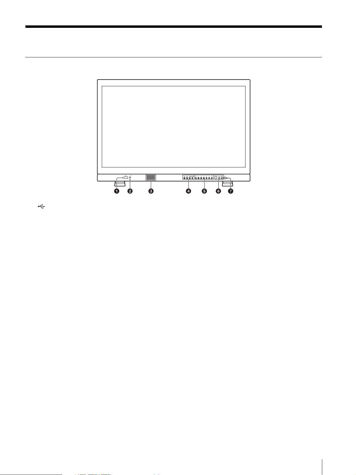
Location and Function of Parts and Controls
Front Panel
(USB) connector
Used for future expansion.
(headphones) jack
The audio signal which is selected by the input select
button is output in stereo sound.
Speaker
The audio signal which is selected by the input select
button is output in monaural sound (L + R).
The outputting audio can be changed in [Audio Setting]
(page 27) of the [User Configuration] menu.
The audio signals from the speaker are output from the
AUDIO OUT connector on the rear (see page 14).
Audio signals will not be output when headphones are
connected to the jack.
Input select buttons
Press to monitor the signal input to each connector.
SDI 1 button: to monitor the signal through the SDI
IN connector
SDI 2 button: to monitor the signal through the SDI
IN connector
HDMI button: to monitor the signal through the
HDMI IN connector
COMPOSITE button: to monitor the signal through
the COMPOSITE IN connector
Function buttons
You can turn the assigned function on or off.
The factory setting is as follows;
F1 button: [Brightness]
F2 button: [Contrast]
F3 button: [Chroma]
F4 button: [Scan]
F5 button: [Marker]
F6 button: [Volume]
F7 button: [WFM/ALM/Vector]
You can assign various functions in [Function Button
Setting] (page 23) of the [User Configuration] menu.
Press the button [Brightness], [Contrast], [Chroma],
[Volume], [WFM Line Position], [Phase], [Aperture], or
[Focus Gain] function assigned to display the
adjustment screen. Press the same button again, and the
adjustment screen disappears, but you can adjust the
value without the setting value display.
Menu operation buttons
Displays or sets the on-screen menu.
Menu selection control
When the menu is displayed, turn the control to select
a menu item or setting value, and then press the
control to confirm the setting.
If the menu is not displayed and the menu selection
control is pressed, the characters that represent the
names of the buttons light up. Also, the names of the
functions assigned to the function buttons appear on
the screen. Press again to clear it.
Alternatively, if the menu is not displayed and the
menu selection control is pressed for more than two
seconds, the signal format is displayed on the screen.
BACK button
Location and Function of Parts and Controls
11
Page 12

When the menu is displayed, press the button to reset
the value of an item to the previous value (except some
items).
MENU button
Press to display the on-screen menu.
Press again to clear the menu.
(Power) switch and indicator
When the unit is turned off, press the switch to turn it
on. The indicator lights in green.
Press the switch again to turn off the unit. The indicator
goes out.
About error/warning signals of the indicator
While the unit is in use, error or warning signals may
appear on the (Power) switch indicator of the front
panel.
Refer to Sony qualified service personnel should any
error display appear.
Error display Symptom
Flashes red There is an abnormality with the panel,
power or sensor. The error also displays
if the DC input voltage goes outside the
acceptable range (PVM-A170 only).
Warning display Symptom
Flashes amber Decreases the brightness to protect the
panel from overheating.
Lights amber The screen is at its brightest. Use with
the contrast or brightness decreased.
12
Location and Function of Parts and Controls
Page 13

Input Signals and Adjustable/Setting Items
Item
[Color Temp]
[Color Space]
[Gamma]
[Aperture]
[V Sharpness]
[ACC]
[Shift H], [Shift V]
[SDI RGB Range]
[DVI RGB Range]
[NTSC Setup]
[Flicker Free]
[Marker]
[Time Code]
[Focus Assist]
[WFM/ALM/Vector]
[Closed Caption]
[Scan]
[Aspect]
[Blue Only]
[Mono]
[Brightness]
[Contrast]
[Chroma]
[Phase]
: Adjustable/can be set
× : Not adjustable/cannot be set
Composite SDI HDMI HDMI/DVI
Color B & W SD HD 3G SD HD PC
×
ЧЧЧЧЧЧ
ЧЧЧЧЧЧЧ
ЧЧЧЧЧЧ
××××
ЧЧЧЧЧЧЧ
ЧЧЧЧЧЧ
×
×××××
×××
××
××
×× ××
5)
ЧЧЧЧЧЧЧ
4)
Input signal
1)
3)
×××
2)
3)
3)
3)
××××
1) Available only when RGB format signal is input.
2) Available only when DVI/PC signal format is input.
HDMI/PC is followed by AVI info.
3) When RGB format signal is input, [Vector] does not
function.
4) Available only when 480/59.94i format signal is input.
5) Available only when NTSC format signal is input.
Location and Function of Parts and Controls
13
Page 14

Rear Panel
Note
Note
PVM-A250
PVM-A170
SDI (3G/HD/SD) input and output connectors
(BNC)
IN connector, IN connector
Input connector for serial digital component signals.
SDI 1 and SDI 2 inputs are available.
OUT connector, OUT connector
Output connector for serial digital component signals.
SDI 1 and SDI 2 outputs are available.
Output is only activated when the power is on.
COMPOSITE input and output connectors
(BNC)
IN connector
Input connector for composite video signals.
OUT connector
Loop-through output connector.
When inputting a video signal with the jitters, etc. the
picture may be disturbed. We recommend using the
TBC (time base corrector).
AUDIO input and output connectors (stereo mini
jack)
IN connector
Connect to the audio outputs of external equipment
such as a VCR.
OUT connector
Outputs the audio signal which is selected by the input
select button on the front panel.
14
Location and Function of Parts and Controls
Page 15

The outputting audio can be changed in [Audio
Note
Note
CAUTION
CAUTION
Close
Cable
Setting] (page 27) of the [User Configuration] menu.
Output is only activated when the power is on.
Pin assignment
HDMI cable holder
Secures the HDMI cable (Ø7 mm or less).
HDMI IN connector
Input connector for HDMI
1)
signals.
HDMI (High-Definition Multimedia Interface) is an
interface that supports both video and audio on a single
digital connection, allowing you to enjoy high quality
digital picture and sound. The HDMI specification
supports HDCP (High-bandwidth Digital Content
Protection), a copy protection technology that
incorporates coding technology for digital video signals.
1) The terms HDMI and HDMI High-Definition Multimedia
Interface, and the HDMI Logo are trademarks or
registered trademarks of HDMI Licensing LLC in the
United States and other countries.
Pin number Functions
1 Designating [SDI1] input signal
2 Designating [SDI2] input signal
3 Designating [HDMI] input signal
4 Designating [Composite] input signal
5GND
6 [WFM/ALM/Vector]
7 [Tally Green]
8 [Tally Red]
You can allocate functions using the [Remote] menu (see
page 28).
Wiring required to use the Remote Control
Connect the function you want to use with a Remote
Control to the Ground (Pin 5).
SERIAL REMOTE connector (RJ-45)
Connect to the Sony BKM-15R/16R Monitor Control
Unit by using a 10BASE-T/100BASE-TX LAN cable
(shielded type, optional).
Use an HDMI cable bearing the High-Speed logo (Sony
product recommended).
PARALLEL REMOTE connector (RJ-45, 8-pin)
Forms a parallel switch and controls the monitor
externally.
For safety, do not connect the connector for peripheral
device wiring that might have excessive voltage to this
port. Follow the instructions for this port.
For safety, do not connect the connector for peripheral
device wiring that might have excessive voltage to this
port. Follow the instructions for this port.
When you connect the SERIAL REMOTE cable of the
unit to peripheral device, use a shielded-type cable to
prevent malfunction due to radiation noise.
The connection speed may be affected by the network
system. This unit does not guarantee the
communication speed or quality of 10BASE-T/
100BASE-TX.
Location and Function of Parts and Controls
15
Page 16

(DC) input connector (PVM-A170 only)
CAUTION
Note
Plug the DC power supply to this connector to provide
power to the monitor.
It runs on DC 12 V to 16 V.
Be sure to connect to a power supply of the specified
voltage.
Pin assignment
Pin number Functions
1– (GND)
2– (GND)
3 + (DC 12 V to 16 V)
4 + (DC 12 V to 16 V)
Removing the Monitor Stand (Pre-Attached)
To install the monitor on a rack, remove the bottom
stand as follows.
1
Put the monitor on a soft cloth with the surface of
the monitor downward.
2
Remove the one screw.
3
Remove the stand.
If only the 1st and 4th pins are connected the unit may
function, but this is not guaranteed. You should connect
all four pins to use the external DC power supply.
AC IN socket
Connect the supplied AC power cord.
16
Removing the Monitor Stand (Pre-Attached)
Page 17

Attaching the handle
AC IN socket
AC power cord
AC plug holder
(supplied)
Connecting the AC Power
(PVM-A170 only)
The handle (supplied) can be attached to the rear panel
using the four screws (supplied).
Cord
1
Plug the AC power cord into the AC IN socket on
the rear panel. Then, attach the AC plug holder
(supplied) to the AC power cord.
2
Slide the AC plug holder over the cord until it locks.
To remove the AC power cord
Pull out the AC plug holder while pressing the lock
levers.
Attaching the handle (PVM-A170 only) / Connecting the AC Power Cord
17
Page 18

Initial settings
BACK button
Using the Menu
When you turn on the unit for the first time after
purchasing it, select the language you wish to use. You
can select the language from among English, French,
German, Spanish, Italian, Japanese, Simplified Chinese.
For details on operating the unit, see “Using the Menu”
(page 18).
When the language has been selected, the following
items are set.
Language [Color Temp] [NTSC Setup]
English
French
German
Spanish
Ita lian
Japanese
Simplified Chinese
The setting of the color temperature and NTSC setup
can be changed. For details, refer to the following pages.
[Color Temp] (page 21)
[NTSC Setup] (page 22)
[D65] [7.5]
[D93] [0]
[D65] [7.5]
The unit is equipped with an on-screen menu for
making various adjustments and settings such as picture
control, input setting, set setting change, etc.
The current settings are displayed in place of the
marks on the illustrations of the menu screen.
1
Press the MENU button.
The menu appears.
The menu presently selected is shown in yellow.
18
Initial settings / Using the Menu
2
Turn the menu selection control to select a menu,
then press the menu selection control.
The menu icon presently selected is shown in
yellow and setting items are displayed.
3
Select an item.
Page 19

Turn the menu selection control to select the item,
Notes
then press the menu selection control.
The item to be changed is displayed in yellow.
If the menu consists of multiple pages, turn the
menu selection control to go to the desired menu
page.
Adjustment Using the Menus
4
Make the setting or adjustment on an item.
When changing the adjustment level:
To increase the number, turn the menu selection
control right.
To decrease the number, turn the menu selection
control left.
Press the menu selection control to confirm the
number, then restore the original screen.
When changing the setting:
Turn the menu selection control to change the
setting, then press the menu selection control to
confirm the setting.
When returning the adjustment or setting to the
previous value:
Press the BACK button before pressing the menu
selection control.
An item displayed in black cannot be accessed.
You can access the item if it is displayed in white.
If the [Key Inhibit] has been turned [On], all
items are displayed in black. To change any of the
items, turn the [Key Inhibit] to [Off] first.
Items
The screen menu of this monitor consists of the
following items.
[Status] (the items indicate the current
settings.)
Displays the unit setting status, etc.
For details on the displayed items, see “[Status] menu”
(page 20).
[Color Temp/Color Space/Gamma]
[Color Temp]
[Manual Adjustment]
[Color Space]
[Gamma]
[User Control]
[Volume]
[Aperture]
[Composite Video Control]
For details on the key inhibit, see “[Key Inhibit]
menu” (page 29).
To return the display to the previous screen
Press the BACK button.
To clear the menu
Press the MENU button.
The menu disappears automatically if a button is not
pressed for one minute.
About the memory of the settings
The settings are automatically stored in the monitor
memory.
[User Configuration]
[System Setting]
[Language]
[SDI RGB Range]
[DVI RGB Range]
[NTSC Setup]
[LED Brightness]
[Screen Saver]
[Format Display]
[Flicker Free]
[Function Button Setting]
[Marker Setting]
[Marker]
[Aspect Marker]
[Center Marker]
[Area Marker]
[Marker Intensity]
[Aspect Mat]
[Time Code Setting]
[Time Code]
[Format]
[Position]
[Focus Assist Setting]
[Focus Assist]
[Focus Mode]
Adjustment Using the Menus
19
Page 20

[Frequency]
[Range]
[Gain]
[WFM/ALM/Vector (waveform monitor, audio level
meter, and vectorscope) Setting]
[Display]
[WFM/ALM/Vector]
[Position]
[Intensity]
[Zoom]
[Line Select]
[Target]
[Audio Setting]
[SDI Audio Setting]
[Analog Audio Output]
[Closed Caption Setting]
[Closed Caption]
[Type]
[708]
[608]
[Intensity]
[On Screen Tally Setting]
[Tally Bckgnd Display]
Page 2
Color temperature
Color space
Gamma
Brightness
Contrast
Chroma
Aperture
Page 3 (for the SDI signal input)
[Remote]
[Parallel Remote]
[Serial Remote]
[Key Inhibit]
[Key Inhibit]
Adjusting and Changing the Settings
[Status] menu
The status menu displays the current status of the unit.
The following items are displayed:
Page 1
Format
RGB range
Scan mode
Flicker free
Payload ID
Video standard
Bit depth
Sampling structure
Picture rate
Scanning method
Page 3 (for the HDMI signal input)
Pixel encoding
RGB range
Color depth
Matrix
fH
fV
20
Adjustment Using the Menus
Page 21

Page 3 (for the composite signal input)
Note
Phase
V sharpness
NTSC setup
ACC
Shift H
Shift V
Page 4
Model name
Serial No.
Software version
FPGA1 version
FPGA2 version
[Color Temp/Color Space/Gamma] menu
This menu is used for adjusting the color temperature,
color space and gamma.
You need to use the measurement instrument to adjust
the white balance.
Recommended: Konica Minolta Color Analyzer CA210/CA-310
Submenu Setting
[Color Temp] Selects the color temperature from
among [D65], [D93], [User1], [User2].
If you measure the color temperatures
of different display types, such as CRT,
LCD, or OLED, by using a common (or
general) color analyzer that is based on
CIE 1931, and adjust the xy
chromaticity to the same value, the
appearance may be different because of
optical spectrum differences.
To compensate for this difference, the
[D65] and [D93] settings of the monitor
are adjusted by an offset
1)
.
1) The offset value applied (x-0.006, y-
0.011) is based on the Judd's function
to the CIE 1931 (x, y) value.
[Manual Adjustment] If you set the [Color Temp] to the
[User1] or [User2] setting, the item
displayed is changed from black to
white, which means you can adjust the
color temperature.
The set values are memorized.
[Adjust Gain/Bias]:
[R Gain]: Adjusts the color
balance (gain) of R (red).
[G Gain]: Adjusts the color
balance (gain) of G (green).
[B Gain]: Adjusts the color
balance (gain) of B (blue).
[R Bias]: Adjusts the color
balance (bias) of R (red).
[G Bias]: Adjusts the color
balance (bias) of G (green).
[B Bias]: Adjusts the color
balance (bias) of B (blue).
[Copy From]: If you select [D65] or
[D93], the white balance data for
the selected color temperature
will be copied to the [User1] or
[User2] setting.
[Color Space] Selects the color space from among
[ITU-709], [EBU], [SMPTE-C], [SGAMUT], [Native]. [Native] sets the
color space to the original color
reproduction of the panel.
[Gamma] Select the appropriate gamma mode
from among [2.2], [2.4], [CRT], [SLOG2 to 709(800%)].
The factory setting is gamma 2.4 that is
specified by ITU-R BT.1886. By using
this gamma the dark areas may appear
darker than that of a CRT or LCD. If
you want to set the gamma to that of a
CRT or LCD, select [CRT] or [2.2].
Also, if the shaded areas lack detail,
adjust [Brightness] (page 23).
Adjustment Using the Menus
21
Page 22

[User Control] menu
The user control menu is used for adjusting the picture.
Submenu Setting
[Volume] Adjusts the volume.
[Aperture] Sharpens the picture outline. The
higher the setting, the sharper the
picture. The lower the setting, the softer
the picture. The aperture does not work
when [Focus Assist] is [On].
[Composite Video
Control]
[V Sharpness]: A crisp image can be
displayed.
When the setting is higher, the
picture becomes even more
crisp.
[ACC] (Auto Color Control): Sets
the ACC circuit [On] or [Off].
To confirm the fine adjustment,
select [Off]. Normally select
[On].
[Shift H]: Adjusts the position of the
picture. As the setting increases,
the picture moves to the right,
and as the setting decreases, the
picture moves to the left.
[Shift V]: Adjusts the position of the
picture. As the setting increases,
the picture moves up, and as the
setting decreases, the picture
moves down.
[User Configuration] menu
The user configuration menu is used for [System
Setting], [Function Button Setting], [Marker Setting],
[Time Code Setting], [Focus Assist Setting], [WFM/
ALM/Vector (waveform monitor, audio level meter, and
vectorscope) Setting], [Audio Setting], [Closed Caption
Setting] and [On Screen Tally Setting].
[System Setting]
Submenu Setting
[Language] Selects the menu or message language
from among seven languages.
[English]: English
[Français]: French
[Deutsch]: German
[Español]: Spanish
[Italiano]: Italian
[]: Japanese
[]: Chinese
[SDI RGB Range] Sets the black level and white level for
the RGB format of SDI input.
[Limited]: [64] (black level) to [940]
(white level)
[Full]: [0] (black level) to [1023]
(white level)
[DVI RGB Range] Sets the black level and white level for
the RGB format of DVI input.
[Limited]: [16] (black level) to [235]
(white level)
[Full]: [0] (black level) to [255] (white
level)
[NTSC Setup] Selects the NTSC setup level from two
modes.
The 7.5 setup level is used mainly in
North America. The 0 setup level is
used mainly in Japan. You can select
between [0] and [7.5].
[LED Brightness] Selects the brightness of the indicator’s
LED of the buttons and power switch.
[High]: The LED becomes brighter.
[Low]: The LED becomes darker.
[Screen Saver] Sets the screen saver function [On] or
[Off ].
[On]: If a still image is displayed for
more than 10 minutes, the
brightness of the screen is
automatically decreased to
reduce burn-in. The screen
returns to normal brightness
when you input an image to the
unit or operate the buttons on
the front panel of the unit. While
the screen saver is activated, the
LED of the selected input select
button flashes (To decrease the
brightness of the LED, see [LED
Brightness] (page 22)).
[Off]: The screen saver function is
deactivated.
22
Adjustment Using the Menus
Page 23

Submenu Setting
[Format Display] Selects the display mode of the signal
format.
[Auto]: The format and scan mode
are displayed for about five
seconds when the input of the
signal starts.
[Off]: The display is hidden.
[Flicker Free] Set this to [On] to enable view images
without flicker.
An OLED panel can provide superior
video responsiveness and scan driving,
reproducing images with little
contouring or afterimaging. However,
scan driving can cause flicker when
input signals have a low vertical
frequency (24P/PsF, 50i, etc.). Set
[Flicker Free] to [On] to greatly reduce
this phenomenon.
With this mode set to on, quick-moving
images may exhibit contours or an
afterimage.
[WFM/ALM/Vector]
Press the button to display the WFM/ALM/vectorscope
display. Set the WFM/ALM/vectorscope display setting
in the [WFM/ALM/Vector Setting] menu (see page 25).
[WFM/VS Zoom]
Press the button to zoom in the WFM/vectorscope
display. Set the zoom setting in the [WFM/ALM/Vector
Setting] menu (see page 26).
[WFM Line Position]
Press the button to display the adjustment screen and
adjust the WFM line position. Press again to hide the
adjustment screen. However, the WFM line position
remains adjustable. Turn the menu selection control
right to lower the line position, or left to raise it.
[Time Code]
Press the button to display the time code display. Adjust
the settings for the time code display in [Time Code
Setting] (see page 25).
[Function Button Setting]
Submenu Setting
[F1] to [F7] Assigns the function to the function
buttons of the front panel and turns the
function on or off.
About the function assigned to the function
button
[Marker]
Press the button to display the marker. Set the marker in
the [Marker Setting] menu (see page 24).
[Focus Assist]
Press the button to confirm the camera focus. An image
with sharpened edges is displayed. Set the camera focus
in [Focus Assist Setting] (see page 25).
[Mono]
Press the button to display a monochrome picture.
When the buttons is pressed again, the monitor switches
automatically to color mode.
[Blue Only]
Press the button to eliminate the red and green signals.
Only blue signal is displayed as an apparent
monochrome picture on the screen. This facilitates
“chroma” and “phase” adjustments and observation of
signal noise.
[Scan]
Press the button to change the scan size of the picture.
With every press of the button, the picture switches in
the sequence [Normal] scan or [Native] scan. (see “Scan
mode image” (page 24)).
[Aspect]
Press the button to set the aspect ratio of the picture,
[16:9] or [4:3].
[Brightness]
Press the button to display the adjustment screen and
adjust the picture brightness. Press again to hide the
adjustment screen. However, the picture brightness
remains adjustable. Turn the menu selection control
right to increase the brightness, or left to decrease it.
[Focus Gain]
Press the button to display the adjustment screen and
adjust the level of edge sharpening. Press again to hide
the adjustment screen. However, the level of edge
sharpening remains adjustable. Turn the menu selection
control right to increase the edge sharpening, or left to
decrease it.
[Contrast]
Press the button to display the adjustment screen and
adjust the picture contrast. Press again to hide the
adjustment screen. However, the picture contrast
remains adjustable. Turn the menu selection control
right to increase the contrast, or left to decrease it.
Adjustment Using the Menus
23
Page 24

[Chroma]
Press the button to display the adjustment screen and
adjust the color intensity. Press again to hide the
adjustment screen. However, the color intensity remains
adjustable. Turn the menu selection control right to
increase the intensity, or left to decrease it.
[Phase]
Press the button to display the adjustment screen and
adjust the color tones. Press again to hide the adjustment
screen. However, the color tones remain adjustable. Turn
the menu selection control right to increase the green
tone, or left to increase the purple tone.
[Aperture]
Press the button to display the adjustment screen and
sharpen the picture outline. Press again to hide the
adjustment screen. However, the picture sharpness
remains adjustable. Turn the menu selection control
right to make the picture sharper, or left to make the
picture softer.
[Volume]
Press the button to display the adjustment screen and
adjust the volume. Press again to hide the adjustment
screen. However, the volume remains adjustable. Turn
the menu selection control right to increase the volume,
or left to decrease it.
Scan mode image
InputNormal scan
480i, 575i, 480p, 576p
Vertical pixels are set to
1080 and horizontal
pixels are displayed with
scaling to the appropriate
aspect ratio.
When an NTSC or PAL
signal is input, the screen
(zeroscan)
may appear small
depending on the signal.
480i, 575i, 480p, 576p
Horizontal pixels are set
to 1920 and vertical pixels
are displayed with scaling
to the appropriate aspect
ratio.
When an NTSC or PAL
signal is input, the screen
may appear small
depending on the signal.
1080i, 1080PsF, 1080p,
720p
[Closed Caption]
Press the button to display the closed caption. Set the
closed caption setting in the [Closed Caption Setting]
menu (see page 27).
[Flicker Free]
Press the button to change the flicker free setting.
480i, 575i, 480p, 576p
Displays the original
video signal pixels. If a
format other than 640 ×
480p is input, the screen
will not be displayed in
Native scan
the appropriate aspect
ratio.
[Marker Setting]
1080i, 1080PsF, 1080p
720p
24
Adjustment Using the Menus
Page 25

Submenu Setting
[Marker] Selects [On] to display the marker and
[Off] not to display.
[Aspect Marker] Selects the aspect ratio of the aspect
marker. You can select from among
[Off], [4:3], [16:9], [15:9], [14:9], [13:9],
[1.85:1], [2.35:1].
[Center Marker] Selects [On] to display the center
marker of the picture and [Off] not to
display.
[Area Marker] Selects the safe area size for the aspect
marker. When the aspect marker is set
to [Off], this menu selects the safe area
size for the effective screen area. You
can select from among [Off], [80%],
[85%], [88%], [90%], [93%], [95%].
[Marker Intensity] Sets the luminance to display the
[Aspect Marker], [Center Marker], and
[Area Marker]. You can select between
[High] and [Low].
[Aspect Mat] Selects whether you put mat on the
outside of the marker display.
[Off]: No mat is put.
[Gray]: Gray mat is put.
[Time Code Setting]
[Focus Assist Setting]
Submenu Setting
[Focus Assist] Selects [On] to use the camera focus
and [Off] not to use.
[Focus Mode] Switches the camera focus mode.
[Color]: Displays the intensified areas
of images with color selected in
the color setting below.
[Color]: Selects the displayed
intensified color from among
[Red], [Green], [Blue],
[Yellow], [White].
[Standard]: An image with
sharpened edges is displayed.
[Frequency] Sets the center frequency of the edge
sharpening signal. You can select from
among [Low], [Middle], [Middle High],
[High].
[Range] Sets the target of edge sharpening. You
can select from among [Narrow],
[Middle], [Wide].
[Gain] Sets the level of edge sharpening.
Submenu Setting
[Time Code] Selects [On] to display the time code
and [Off] not to display.
[Format] Sets the time code format.
[VITC]: To display the time code in
VITC format.
[LTC]: To display the time code in
LTC f ormat.
[Position] Sets the position of the time code
display. You can select between [Top]
and [Bottom].
[WFM/ALM/Vector (waveform monitor,
audio level meter, and vectorscope) Setting]
Submenu Setting
[Display] Select [On] to display the [WFM]
(waveform monitor), [ALM] (audio
level meter), or [Vector] (Vectorscope);
or [Off] not to display.
Adjustment Using the Menus
25
Page 26

Submenu Setting
When [WFM] is selected
Waveform
Audio level
Channel number
When [ALM] is selected
Audio level
Channel number
(When SDI signal is input, the eight channels are
displayed, including the channel which is selected in
[SDI Audio Setting]. The selected channels are displayed
brightly.)
When [Vector] is selected
Red
Magenta
Audio level
Bar I
Yellow
Bar Q
Black
Green
Cyan
Blue
Color target frame
Channel number
[WFM/ALM/Vector] [WFM]: Displays the waveform
monitor.
[ALM]: Displays the audio level
meter.
[Vector]: Displays the vectorscope.
When [WFM] is selected, the waveform
and audio level are displayed. When
YCbCr format signal is input, the Y
signal waveform is displayed. When
RGB format signal is input, the G signal
waveform is displayed. When [ALM] is
selected, the audio level is displayed in
eight channels.
When [Vector] is selected, the color
component of the image signal and the
audio levels are displayed.
When SDI signal is input, the audio
levels for channels selected in [SDI
Audio Setting] are displayed.
Each display type is illustrated below.
(The waveform percentage and audio
level units/values do not appear on the
display.)
Submenu Setting
26
Adjustment Using the Menus
[Position] Sets the position of the WFM/ALM/
vectorscope display. You can select from
among [Top Left], [Top Right], [Bottom
Left], [Bottom Right].
[Intensity] Sets the brightness of the waveform, etc.
You can select from among [Low],
[Middle], [High].
[Zoom] When [On] is set, 0-20 IRE areas will be
zoomed when [WFM] is selected, or
black areas will be zoomed when
[Vector] is selected.
Page 27

Submenu Setting
[Line Select] Select [On] to display the waveform of
the line assigned in [Position] below,
when [WFM] is selected.
[Color]: Selects the displayed line
color from among [Red], [Green],
[Blue], [Yellow], [White].
[Position]: Sets the line position.
When the numerical value is
increased, the line will move down;
when decreased, the line will move
up.
[Target] Select [75%] or [100%]. Switches the
vectorscope target between 75% and
100%.
[Audio Setting]
Submenu Setting
[SDI Audio Setting] Sets the audio channel when SDI signal
[Analog Audio
Output]
is input.
[Left Audio]: Selects from channels
[CH1] to [CH16].
[Right Audio]: Selects from channels
[CH1] to [CH16].
When a channel from [CH1] to [CH8]
is selected in [Left Audio], you can
select a channel from [CH1] to [CH8]
in [Right Audio]. When a channel from
[CH9] to [CH16] is selected in [Left
Audio], you can select a channel from
[CH9] to [CH16] in [Right Audio].
You can display the L/R audio levels of
the selected channels. (see [WFM/
ALM/Vector (waveform monitor, audio
level meter, and vectorscope) Setting]
(page 25)).
Select an audio format to output from
speakers, headphone jack, and AUDIO
OUT connector.
[Embedded]: Outputs an audio signal
embedded in SDI or HDMI
signal.
[Analog]: Outputs an audio signal
that comes from the AUDIO IN
connector.
[Closed Caption Setting]
Submenu Setting
[Closed Caption] Select [On] to display closed caption
and [Off] not to display.
[Type] Sets the closed caption display type.
[708] Sets the closed caption type for 708.
[608] Sets the closed caption type for
[Intensity] Sets the luminance of the displayed
[Auto1]: Select this to display
automatically 608(VBI)
SD-SDI signal is input, or to
display automatically 708
3)
when
1)
when HD-SDI signal is input.
[Auto2]: Select this to display
automatically 608(VBI)
3)
when
SD-SDI signal is input, or to
display automatically 608(708)
when HD-SDI signal is input.
[708]: Select this to display 708
when HD-SDI signal is input.
[608(708)]: Select this to display
608(708)
2)
when HD-SDI signal
is input.
[608(VBI)]: Select this to display
608(VBI)
3)
when SD-SDI signal
is input.
1) 708 is a closed caption signal
conforming to the EIA/CEA-708
standard.
2) 608(708) is a closed caption signal
conforming to the EIA/CEA-608
standard, and which is transmitted as
EIA/CEA-708 standard.
3) 608(VBI) is a closed caption signal
conforming to the EIA/CEA-608
standards, and which is transmitted
as Line 21.
Select from [Service1] to [Service6].
608(708) and 608(VBI). Select from
among [CC1], [CC2], [CC3], [CC4],
[Text1], [Text2], [Text3], [Text4].
characters. Select [Low] or [High].
2)
1)
Adjustment Using the Menus
27
Page 28

[On Screen Tally Setting]
Notes
Note
Submenu Setting
[Tally Bckgnd
Display]
The tally is displayed on the screen of
this unit.
When [Tally Bckgnd Display] is set to
[On], the mat is displayed on the tally
display area. When [Off], the tally is
displayed directly on the video signal.
[Remote] menu
[Parallel Remote]
Submenu Setting
[Parallel Remote] Selects the PARALLEL REMOTE
connector pins for which you want to
change the function.
You can assign various functions to pins
1 to 4 and pins 6 to 8. The following lists
the functions you can assign to the pins.
[SDI1]
[SDI2]
[HDMI]
[Composite]
[80% Area Maker]
[85% Area Maker]
[88% Area Maker]
[90% Area Maker]
[93% Area Maker]
[95% Area Maker]
[Center Marker]
[16:9 Marker]
[15:9 Marker]
[14:9 Marker]
[13:9 Marker]
[1.85:1 Marker]
[2.35:1 Marker]
[4:3 Marker]
[Aspect Mat]
[Tally Red]
[Tally Green]
[Normal Scan]
[Native Scan]
[4:3]
[16:9]
[WFM/ALM/Vector]
[Focus Assist]
[Mono]
[Blue Only]
[Flicker Free]
[– – –] ([– – –]: No function is
assigned.)
If you use the parallel remote
function, you need to connect
cables. For more details, see page 15.
Set [Marker] (page 25) in [Marker
Setting] to [On] to control the aspect
marker and center marker.
[Forced Tally] The tally lamp function is forcibly
assigned to 7 pin and 8 pin of the
PARALLEL REMOTE connector.
Selecting [On] assigns tally lamp green
to 7 pin and tally lamp red to 8 pin.
[Off]: The tally lamp function is
not forcibly assigned.
[On]: Forcibly assigns the tally
lamp function.
When [Off] is selected, any listed
functions can be assigned to 7 and 8
pins. Selecting [On] with any function
other than the tally lamp assigned to 7
and 8 pins will ignore this setting, and
the tally lamp is forcibly assigned to 7
and 8 pins instead.
28
Adjustment Using the Menus
Page 29

[Serial Remote]
Submenu Setting
[Serial Remote] Selects the mode to be used.
[Off]: The serial remote does not
function.
[On]: The serial remote functions.
[Monitor] Sets the monitor setting.
[Monitor ID]: Sets the ID of the
monitor.
[Group ID]: Sets the group ID of the
monitor.
[IP Address]: Sets the IP address.
[Subnet Mask]: Sets the subnet mask.
([255.255.255.000])
[Default Gateway]: Sets the default
gateway [On] or [Off].
[Address]: Sets the default
gateway.
[Cancel]: Selects to cancel the setting.
[Confirm]: Selects to save the setting.
[Controller] Sets the address of the remote
controller.
[IP Address]: Sets the IP address.
[Subnet Mask]: Sets the subnet mask.
([255.255.255.000])
[Default Gateway]: Sets the default
gateway [On] or [Off].
[Address]: Sets the default
gateway.
[Cancel]: Selects to cancel the setting.
[Confirm]: Selects to save the setting.
[Connection] Sets the connection of the monitor and
the controller.
[LAN]: for connection via a
network
[Peer to Peer]: for one to one
connection
Troubleshooting
This section may help you isolate the cause of a problem
and as a result, eliminate the need to contact technical
support.
The unit cannot be operated The key protection
function works. Set the [Key Inhibit] setting to [Off ] in
the [Key Inhibit] menu.
Or, a function that does not work is assigned to a
function button. When the menu is not displayed,
press the menu selection control to confirm the
functions assigned to function buttons.
The black bars appear at the upper and lower or left
and right positions of the display When the
signal aspect ratio is different from that of the panel,
the black bars appear. This is not a failure of the unit.
Adjustments and settings cannot be made
Adjustments and settings may not be possible
depending on the input signals and the status of the
unit. See “Input Signals and Adjustable/Setting Items”
(page 13).
The screen becomes dark and the unit turns off
If the internal temperature of the unit increases,
the screen may become dark and the unit may turn off.
In this case, refer to Sony qualified service personnel.
[Key Inhibit] menu
You can lock the setting so that they cannot be changed
by an unauthorized user. Select [Off] or [On].
If you set to [On], all items are displayed in black,
indicating the items are locked.
Troubleshooting
29
Page 30

Specifications
Picture performance
Panel OLED panel
Picture size (diagonal)
PVM-A250: 623.4 mm (24
PVM-A170: 419.7 mm (16
Effective picture size (H × V)
PVM-A250: 543.4 × 305.6 mm
1
(21
/2 × 12 1/8 inches)
PVM-A170: 365.8 × 205.7 mm
1
(14
/2 × 8 1/8 inches)
Resolution (H × V)
1920 × 1080 pixels (Full HD)
Aspect 16:9
Pixel efficiency 99.99%
Panel drive RGB 10-bit
Viewing angle (Panel specification)
89°/89°/89°/89° (typical)
(up/down/left/right, contrast > 10:1)
Normal scan 0% scan
Color temperature
D65, D93
Warm-up time Approx. 30 minutes
To provide stable picture quality, turn
on the power of the monitor and
leave it in this state for more than 30
minutes.
Input
SDI input connector
BNC type (2)
HDMI input connector
HDMI (1)
HDCP correspondence
Composite input (NTSC/PAL) connector
BNC type (1)
1 Vp-p ± 3 dB sync negative
Audio input connector
Stereo mini jack (1)
–5 dBu 47 kΩ or higher
Remote input connector
Parallel remote
RJ-45 modular connector 8-pin (1)
Serial remote
RJ-45 modular connector (1)
(ETHERNET, 10BASE-T/100BASETX)
DC input connector
PVM-A170: XLR 4-pin (male) (1)
DC 12 V to 16 V (output impedance
0.05 Ω or less)
Output
SDI (3G/HD/SD) output connector
5
/8 inches)
5
/8 inches)
BNC type (2)
Output signal amplitude: 800 mVp-p
±10%
Output impedance: 75 Ω unbalanced
Composite output connector
BNC type (1)
Loop-through, with 75 Ω automatic
terminal function
Audio monitor output connector
Stereo mini jack (1)
Built-in speaker output
1.0 W Monaural
Headphones output connector
Stereo mini jack (1)
General
Power PVM-A250: AC 100 V to 240 V, 1.3 A
to 0.6 A, 50/60 Hz
PVM-A170: AC 100 V to 240 V, 0.9 A
to 0.5 A, 50/60 Hz
DC 12 V to 16 V, 6.4 A to 4.8 A
Power consumption
PVM-A250:
Approx. 115 W (max.)
Approx. 80 W (average power
consumption in the default status)
PVM-A170:
Approx. 75 W (max.)
Approx. 60 W (average power
consumption in the default status)
Inrush current
PVM-A250:
(1) Maximum possible inrush current
at initial switch-on (Voltage changes
caused by manual switching):
50 A peak, 6 A r.m.s. (240V AC)
(2) Inrush current after a mains
interruption of five seconds (Voltage
changes caused at zero-crossing):
15 A peak, 3 A r.m.s. (240V AC)
PVM-A170:
(1) Maximum possible inrush current
at initial switch-on (Voltage changes
caused by manual switching):
45 A peak, 5 A r.m.s. (240V AC)
(2) Inrush current after a mains
interruption of five seconds (Voltage
changes caused at zero-crossing):
15 A peak, 3 A r.m.s. (240V AC)
Operating conditions
Te m pe r a tu r e
0 °C to 35 °C (32 °F to 95 °F)
Recommended temperature
20 °C to 30 °C (68 °F to 86 °F)
Humidity 30% to 85% (no condensation)
Pressure 700 hPa to 1060 hPa
Storage and transport conditions
30
Specifications
Page 31

Te mp e r a tu r e
Note
–20 °C to +60 °C (–4 °F to +140 °F)
Humidity 0% to 90%
Pressure 700 hPa to 1060 hPa
Accessories supplied
AC power cord (1)
AC plug holder (1)
Handle (1) (PVM-A170 only)
Screws for the handle (4) (PVM-A170
only)
Before Using This Unit (1)
CD-ROM (1)
Optional accessories
Monitor stand
SU-561
Mounting bracket
MB-P17 (For PVM-A170)
Protection kit
BKM-PP25 (For PVM-A250)
BKM-PP17 (For PVM-A170)
Design and specifications are subject to change without
notice.
Notes
Always verify that the unit is operating properly
before use. SONY WILL NOT BE LIABLE FOR
DAMAGES OF ANY KIND INCLUDING, BUT
NOT LIMITED TO, COMPENSATION OR
REIMBURSEMENT ON ACCOUNT OF THE
LOSS OF PRESENT OR PROSPECTIVE PROFITS
DUE TO FAILURE OF THIS UNIT, EITHER
DURING THE WARRANTY PERIOD OR AFTER
EXPIRATION OF THE WARRANTY, OR FOR
ANY OTHER REASON WHATSOEVER.
SONY WILL NOT BE LIABLE FOR CLAIMS OF
ANY KIND MADE BY USERS OF THIS UNIT
OR MADE BY THIRD PARTIES.
SONY WILL NOT BE LIABLE FOR THE
TERMINATION OR DISCONTINUATION OF
ANY SERVICES RELATED TO THIS UNIT
THAT MAY RESULT DUE TO
CIRCUMSTANCES OF ANY KIND.
SONY WILL NOT BE LIABLE FOR DAMAGES OF
ANY KIND RESULTING FROM A FAILURE TO
IMPLEMENT PROPER SECURITY MEASURES
ON TRANSMISSION DEVICES, UNAVOIDABLE
DATA LEAKS RESULTING FROM
TRANSMISSION SPECIFICATIONS, OR
SECURITY PROBLEMS OF ANY KIND.
Available video signal formats
The unit is applicable to the following video signal
formats.
System
575/50i (PAL) –
480/60i (NTSC)
576/50p – – –
480/60p
640 × 480/60p
1080/24PsF
1080/25PsF
1080/30PsF
1080/24p
1080/25p –
1080/30p
1080/50i –
1080/60i
1080/50p – –
1080/60p
720/24p
720/25p – ––
720/30p
720/50p –
720/60p
: Adjustable/can be set
– : Not adjustable/cannot be set
1) Compatible with 1/1.001 frame rates.
2) 1080/25PsF, 30PsF are displayed as 1080/25PsF, 30PsF on the screen
3) 10-bit 4:4:4 YCbCr and 4:4:4 RGB of 3G-SDI signals are supported.
4) 10-bit 4:2:2 YCbCr of 3G-SDI signal is supported.
1)
1)
2)
1) 2)
1)
1)
1)
1)
1)
1)
1)
if the payload ID is added to the video signal, or displayed as 1080/50I,
60I if the ID is not added.
1)
Composi te
1)
–
SD/HD 3G HDMI
–––
–––
–
–
––
–
–
–
––
– ––
– ––
–
3)
3)
3)
3)
3)
3)
3)
3)
4)
4)
3)
3)
–
–
–
Applicable signals from PC
This unit is compatible with the following PC signals.
System HDMI/DVI
Resolution
640 × 480 25.175 31.5
1280 × 768 68.250 47.4
1280 × 1024 108.000 64.0
1360 × 768 85.500 47.7
1440 × 900 88.750 55.5
1680 × 1050 119.000 64.7
Dot clock
(MHz)
The sides of the displayed picture may be hidden
depending on the input signal.
fH (kHz) fV (Hz)
60
Specifications
31
Page 32

Dimensions
4-M4 hole
5-M4 hole
4-M4 hole
PVM-A250
Front
Rear
Side
Unit: mm (inches)
Mass:
Approx. 6.1 kg (13 lb 7.2 oz)
PVM-A170
Front
Rear
32
Dimensions
Page 33

Side
5-M4 hole
* Length of M4 screws (side)
Monitor cabinet
Attached object
M4 screw
8 (
11
/32) to 12 (1/2)
Torque: 1.2 ± 0.1 N·m
* Length of M4 screws (rear)
Monitor cabinet
Attached object
7 (
9
/32) to 10 (13/32)
M4 screw
Mass:
Approx. 4.2 kg (9 lb 4.2 oz)
PVM-A250/A170
Unit: mm (inches)
Unit: mm (inches)
Dimensions
33
Page 34

Sony Corporation
 Loading...