

Page 1

4-198-307-11 (1)
Solid-State Memory
Camcorder
Operating Instructions
Before operating the unit, please read this manual thoroughly
and retain it for future reference.
PMW-320K
PMW-320L
© 2010 Sony Corporation
Page 2

WARNING
To reduce the risk of fire or
electric shock, do not
expose this apparatus to
rain or moisture.
To avoid electrical shock,
do not open the cabinet.
Refer servicing to qualified
personnel only.
Important Safety Instructions
• Read these instructions.
• Keep these instructions.
• Heed all warnings.
• Follow all instructions.
• Do not use this apparatus near water.
• Clean only with dry cloth.
• Do not block any ventilation openings.
Install in accordance with the
manufacturer’s instructions.
• Do not install near any heat sources such
as radiators, heat registers, stoves, or
other apparatus (including amplifiers) that
produce heat.
• Do not defeat the safety purpose of the
polarized or grounding-type plug. A
polarized plug has two blades with one
wider than the other. A grounding-type
plug has two blades and a third grounding
prong. The wide blade or the third prong
are provided for your safety. If the
provided plug does not fit into your outlet,
consult an electrician for replacement of
the obsolete outlet.
• Protect the power cord from being walked
on or pinched particularly at plugs,
convenience receptacles, and the point
where they exit from the apparatus.
• Only use attachments/accessories
specified by the manufacturer.
• Use only with the cart, stand, tripod,
bracket, or table specified by the
manufacturer, or sold with the apparatus.
When a cart is used, use caution when
moving the cart/apparatus combination to
avoid injury from tip-over.
• Unplug this apparatus during lightning
storms or when unused for long periods of
time.
• Refer all servicing to qualified service
personnel. Servicing is required when the
apparatus has been damaged in any way,
such as power-supply cord or plug is
damaged, liquid has been spilled or
objects have fallen into the apparatus, the
apparatus has been exposed to rain or
moisture, does not operate normally, or
has been dropped.
WARNING
Excessive sound pressure from earphones
and headphones can cause hearing loss.
In order to use this product safely, avoid
prolonged listening at excessive sound
pressure levels.
For the customers in the U.S.A.
This equipment has been tested and found
to comply with the limits for a Class A digital
device, pursuant to Part 15 of the FCC
Rules. These limits are designed to provide
reasonable protection against harmful
interference when the equipment is operated
in a commercial environment. This
equipment generates, uses, and can radiate
radio frequency energy and, if not installed
and used in accordance with the instruction
manual, may cause harmful interference to
radio communications. Operation of this
equipment in a residential area is likely to
cause harmful interference in which case the
user will be required to correct the
interference at his own expense.
You are cautioned that any changes or
modifications not expressly approved in this
manual could void your authority to operate
this equipment.
All interface cables used to connect
peripherals must be shielded in order to
comply with the limits for a digital device
pursuant to Subpart B of Part 15 of FCC
Rules.
2
Page 3

This device complies with Part 15 of the FCC
Rules. Operation is subject to the following
two conditions: (1) this device may not cause
harmful interference, and (2) this device
must accept any interference received,
including interference that may cause
undesired operation.
For the customers in Canada
This Class A digital apparatus complies with
Canadian ICES-003.
For the customers in Europe
This product with the CE marking complies
with the EMC Directive issued by the
Commission of the European Community.
Compliance with this directive implies
conformity to the following European
standards:
• EN55103-1: Electromagnetic Interference
(Emission)
• EN55103-2: Electromagnetic
Susceptibility (Immunity)
This product is intended for use in the
following Electromagnetic Environments: E1
(residential), E2 (commercial and light
industrial), E3 (urban outdoors), E4
(controlled EMC environment, ex. TV
studio).
The manufacturer of this product is Sony
Corporation, 1-7-1 Konan, Minato-ku,
Tokyo, Japan.
The Authorized Representative for EMC and
product safety is Sony Deutschland GmbH,
Hedelfinger Strasse 61, 70327 Stuttgart,
Germany. For any service or guarantee
matters please refer to the addresses given
in separate service or guarantee documents.
For the customers in Taiwan only
For the State of California, USA only
Perchlorate Material - special handling may
apply, See
www.dtsc.ca.gov/hazardouswaste/
perchlorate
Perchlorate Material : Lithium battery
contains perchlorate.
3
Page 4

Table of Contents
Foreword ...................................................................................................... 9
Before Use......................................................................................... 9
Chapter 1 : Overview
Features ...................................................................................................... 10
Using the Software..................................................................................... 11
Reading the CD-ROM Manuals...................................................... 11
System Requirements for Using the Applications .......................... 12
Software Installation ....................................................................... 12
Locations and Functions of Parts and Controls...................................... 13
Power Supply .................................................................................. 13
Accessory Attachments................................................................... 13
Operating and Connectors Section.................................................. 15
Monochrome LCD Panel ................................................................ 24
Auto Focus Lens (Supplied with the PMW-320K)......................... 25
Viewfinder....................................................................................... 26
Viewfinder Screen Display........................................................................ 28
Chapter 2 : Preparations
Preparing a Power Supply ........................................................................ 32
Attaching the Viewfinder .......................................................................... 33
Setting the Area of Use .............................................................................. 38
Setting the Date/Time of the Internal Clock ........................................... 39
Mounting and Adjusting the Lens............................................................ 39
Table of Contents
4
Using a Battery Pack....................................................................... 32
Using AC Power ............................................................................. 33
Attaching the Supplied Viewfinder................................................. 33
Adjusting the Viewfinder Position.................................................. 34
Adjusting the Viewfinder Angle..................................................... 34
Lifting Up the Viewfinder Barrel and Eyepiece ............................. 34
Adjusting the Viewfinder Focus and Screen................................... 36
Using the BKW-401 Viewfinder Rotation Bracket ........................ 36
Attaching a 5-inch Electronic Viewfinder ...................................... 37
Adjusting the Flange Focal Length................................................. 40
Page 5

Preparing the Audio Input System .......................................................... 41
Connecting a Microphone to the MIC IN Connector...................... 41
Connecting Microphones to the AUDIO IN Connectors................ 42
Attaching a UHF Portable Tuner (for a UHF Wireless Microphone
System) ..................................................................................... 43
Tripod Mounting ....................................................................................... 44
Connecting a Video Light ......................................................................... 45
Using the Shoulder Strap .......................................................................... 45
Adjusting the Shoulder Pad Position....................................................... 46
Chapter 3 : Adjustments and Settings
Setting the Video Format .......................................................................... 47
Changing the Video Format............................................................ 48
Adjusting the Black Balance and the White Balance............................. 48
Adjusting the Black Balance........................................................... 48
Adjusting the White Balance .......................................................... 49
Setting the Electronic Shutter................................................................... 52
Shutter Modes ................................................................................. 52
Selecting the Shutter Mode and Shutter Speed............................... 52
Changing the Reference Value for Automatic Iris Adjustment............ 54
Zooming...................................................................................................... 55
Switching between Zoom Modes.................................................... 55
Using Manual Zoom ....................................................................... 55
Using Servo Zoom .......................................................................... 55
Adjusting the Focus ................................................................................... 55
Adjusting in Full MF Mode ............................................................ 55
Adjusting in MF Mode.................................................................... 56
Adjusting in AF Mode .................................................................... 56
Using Macro Mode ......................................................................... 56
Adjusting the Audio Level ........................................................................ 57
Manually Adjusting the Audio Levels of the Audio Inputs from the
AUDIO IN CH1/CH2 Connectors............................................ 57
Manually Adjusting the Audio Level of the MIC IN Connector.... 57
Recording Audio on Channels 3 and 4 ........................................... 58
Setting the Time Data................................................................................ 59
Setting the Timecode....................................................................... 59
Setting the User Bits........................................................................ 60
Synchronizing the Timecode........................................................... 60
Table of Contents
5
Page 6

Checking Camcorder Settings and Status Information (Status Screens)
............................................................................................................... 62
Chapter 4 : Shooting
Handling S×S Memory Cards................................................................... 64
Basic Operations........................................................................................ 68
Advanced Operations ................................................................................ 71
About S×S Memory Cards.............................................................. 64
Loading and Ejecting S×S Memory Cards ..................................... 65
Selecting the S×S Memory Card to Use ......................................... 66
Formatting (Initializing) S×S Memory Cards................................. 66
Checking the Remaining Recording Time...................................... 67
Restoring S×S Memory Cards ........................................................ 67
Playing Recorded Clips................................................................... 69
Deleting Recorded Clips ................................................................. 70
Recording Shot Marks..................................................................... 71
Setting OK Marks ........................................................................... 71
Starting to Record from Pre-stored Video (Picture Cache Function)
.................................................................................................. 71
Recording Time-lapse Video (Interval Rec Function).................... 73
Shooting Stop Motion Animations (Frame Rec Function) ............. 74
Shooting with Slow & Quick Motion ............................................. 75
Framing Shots with the Freeze Mix Function................................. 77
Chapter 5 : Clip Operations
Clip Playback ............................................................................................. 78
Thumbnail Operations.............................................................................. 82
Table of Contents
6
Thumbnail Screen ........................................................................... 78
Playing Clips................................................................................... 80
Using Thumbnails to Search Inside Clips....................................... 81
THUMBNAIL Menu Configuration............................................... 82
Basic THUMBNAIL Menu Operations.......................................... 83
Changing the Thumbnail Screen Type............................................ 83
Displaying Clip Properties .............................................................. 84
Adding and Deleting OK Marks (HD Mode Only) ........................ 85
Copying Clips ................................................................................. 85
Deleting Clips.................................................................................. 86
Displaying the Expand Thumbnail Screen...................................... 87
Displaying the Shot Mark Thumbnail Screen (HD Mode Only).... 88
Adding and Deleting Shot Marks (HD Mode Only)....................... 88
Changing Clip Index Pictures (HD Mode Only)............................. 89
Page 7

Dividing Clips (HD Mode Only) .................................................... 89
Chapter 6 : Menu and Detailed Settings
Setup Menu Organization and Levels...................................................... 90
Setup Menu Organization ............................................................... 90
Setup Menu Levels.......................................................................... 90
Basic Setup Menu Operations .................................................................. 91
Menu List.................................................................................................... 94
OPERATION Menu........................................................................ 94
PAINT Menu................................................................................. 108
MAINTENANCE Menu............................................................... 114
FILE Menu.................................................................................... 125
Assigning Functions to Assignable Switches ......................................... 129
Functions that can be assigned to the ASSIGN. 0 switch............. 129
Functions that can be assigned to the ASSIGN. 2 switch............. 130
Functions that can be assigned to the ASSIGN. 1 and 3 switches, the
ASSIGNABLE 4 and 5 switches, and the COLOR TEMP. button
................................................................................................ 130
Functions that can be assigned to the RET button on the lens...... 132
Adjusting Picture Characteristics to Match the PMW-EX1R ............ 133
Chapter 7 : Saving and Loading User Setting Data
Saving and Loading Settings................................................................... 134
Saving Setting Data....................................................................... 134
Loading Setting Data..................................................................... 135
Resetting a File after Changing Its Contents................................. 135
Saving and Loading Scene Files ............................................................. 136
Saving Scene Files ........................................................................ 136
Loading Scene Files...................................................................... 136
Saving and Loading Lens Files............................................................... 137
Setting Lens File Data................................................................... 137
Saving Lens Files.......................................................................... 137
Loading Lens Files........................................................................ 138
Loading Lens Files Automatically................................................ 138
Chapter 8 : Connecting External Devices
Connecting External Monitors ............................................................... 139
Table of Contents
7
Page 8

Operating Clips with a Computer.......................................................... 141
Connecting an External Device (i.LINK Connection).......................... 143
Recording the Camera Picture on an External Device.................. 143
Nonlinear Editing.......................................................................... 144
Recording External Input Signals ................................................. 144
Chapter 9 : Maintenance
Testing the Camcorder............................................................................ 146
Maintenance............................................................................................. 146
Cleaning the Viewfinder ............................................................... 146
Note about the Battery Terminal................................................... 146
Operation Warnings................................................................................ 147
Appendix
Important Notes on Operation ............................................................... 154
Exchanging the Battery of the Internal Clock ...................................... 156
Specifications............................................................................................ 156
General.......................................................................................... 156
Camera Block................................................................................ 157
Audio Block .................................................................................. 157
Display .......................................................................................... 157
Media Block.................................................................................. 158
Inputs/Outputs............................................................................... 158
Lens Block (PMW-320K only)..................................................... 158
Supplied Accessories .................................................................... 159
Recommended Additional Equipment.......................................... 159
Chart of Optional Components and Accessories .................................. 161
About i.LINK ........................................................................................... 162
MPEG-2 Video Patent Portfolio License............................................... 163
Index.......................................................................................................... 164
Table of Contents
8
Page 9

Foreword
Before Use
After purchasing the PMW-320K/320L SolidState Memory Camcorder, before operating, it is
necessary to set the area of use.
(Unless this setting is made, the camcorder will
not operate.)
For details of these settings, see “Setting the Area of
Use” (page 38).
Note
Before attaching/removing optional components or
accessories to/from the PMW-320K/320L (referred to as
“the camcorder”), be sure to turn the power of the
camcorder off.
Foreword
9
Page 10

Chapter 1 Overview
Chapter1 Overview
Features
The camcorder is a shoulder-mount HD memory
camcorder. It is provided with three
(diagonal 8 mm (
(1920×1080) “Exmor” CMOS image sensors.
1
/2-type bayonet mount
The camcorder is provided with a 1/2-type
bayonet mount (flange focal length 38 mm (
inches), allowing you to use Sony
bayonet mount exchangeable lenses.
11
/32 inches)) full-HD
S×S memory cards as recording media
Using S×S memory cards, the camcorder offers
nonlinear capabilities such as instant random
access and file-based operation.
Light weight, low power consumption
Design features such as CMOS image sensors,
custom video signal processing ICs, and S×S
memory card recording enable fanless operation
and power consumption of 15 W or less. The
camcorder’s light weight (3.2 kg (7 lb 0.88 oz))
and low center of gravity make it easy to carry on
the shoulder while ensuring superior stability.
HD recording using the “MPEG-2 Long
GOP” codec
The camcorder records 1920 × 1080, 1440 ×
1080, and 1280 × 720 HD images using “MPEG2 Long GOP” codec compression. It offers a
choice of bit rates: either 35 Mbps (HQ mode) or
25 Mbps (SP mode).
By utilizing an efficient compression format, the
camcorder records high-quality HD images for
long recording time of approx. 100 minutes at 35
Mbps (HQ mode) or approx. 140 minutes at 25
Mbps (SP mode) on a single 32-GB S×S memory
card.
1
/2-type
1
/2-type
1
/2
Multi-format support
The camcorder supports interlace format
recording (1080/59.94i or 1080/50i), progressive
format recording (1080/29.97P, 1080/23.98P,
720/59.94P, 720/29.97P, 720/23.98P, or 1080/
25P, 720/50P, 720/25P), thus offering the
flexibility needed for worldwide HD recording.
(For 23.98P, native frequency recording is
possible.)
It also supports recording and playback of SD
signals (both NTSC and PAL). The camcorder
has an optional capability to record and play back
SD signals in DVCAM-AVI format, and can
output HD signals down-converted to SD.
A special auto focus lens
The camcorder is provided with the 1/2-type auto
focus lens, which ensures high-quality shooting
in all situations from wide angle to telephoto
(PMW-320K only).
A variety of functions for improved
performance under various shooting
conditions
• Picture Cache function
• Optical ND filters and electrical CC filters
• Hyper gamma
• Slow shutter function
• Frame Recording function
• Time lapse function (interval recording)
• Slow & quick motion function
• Freeze mix function
• Focus magnification function
• Image inversion function
• Assignable switches
• 3.5-inch high-resolution color LCD viewfinder
• Remote control
10
Features
Page 11

Inherits unique features of XDCAM EX
series
The camcorder inherits the workflow features of
the XDCAM EX series, including thumbnail
display and metadata management, and improves
them by introducing an improved man-machine
interface.
XDCAM EX web sites
For information on XDCAM EX, visit the
following web sites:
United States
http://www.sony.com/xdcamex
Canada
http://www.sony.ca/xdcamex
Europe, Middle East, Africa, and Russia
http://www.sonybiz.net/xdcamex
Latin America
http://www.sonypro-latin.com/xdcamex
Australia
http://www.sony.com.au/xdcamex
Asia (except Korea, China, and Japan)
http://pro.sony-asia.com
Korea
http://bp.sony.co.kr/xdcamex
China
http://pro.sony.com.cn/minisite/XDCAMEX
Japan
http://www.sony.co.jp/XDCAMEX
Using the Software
The supplied CD-ROM (labeled “Utility
Software for Solid-State Memory Camcorder and
Recorder”) cont ains application and device driver
software required to access to SxS memory cards
from a computer and to manage material shot
with the camcorder.
Information about how to install the software is
provided in PDF format.
Note
You must install the SxS device driver on your com puter
if your computer is equipped with an ExpressCard slot
and you want to use it to access SxS memory cards.
Reading the CD-ROM Manuals
Preparations
The following program must be installed on your
computer in order to read the operation manuals
contained on the CD-ROM.
Adobe Reader Version 6.0 or higher
Memo
If Adobe Reader is not installed, you can download it
from the following URL:
http://www.adobe.com/
Adobe and Adobe Reader are trademarks of Adobe
Systems Incorporated in the United States and/or other
countries.
Chapter 1 Overview
To read the documents
Do the following:
1 Insert the CD-ROM in your CD-ROM
drive.
A cover page appears automatically in your
browser.
If it does not appear automatically in the
browser, double-click on the index.htm file
on the CD-ROM.
2 Select and click on the manual that you
wish to read.
This opens the PDF file.
Using the Software
11
Page 12

Memo
Chapter 1 Overview
The files may not be displayed properly, depending on
the version of Adobe Reader. In such a case, install the
latest version you can download from the URL
mentioned in “Preparations” above.
Note
If you have lost or damaged the CD-ROM, you can
purchase a new one to replace it. Contact a Sony service
representative.
System Requirements for Using the Applications
The following operating conditions are
recommended for using the software recorded on
the CD-ROM:
S×S Device Driver Software
Applicable hardware
Computer conforming to ExpressCard/34 or
ExpressCard/54
OS
• Microsoft Windows XP SP2 or later, Microsoft
Windows Vista, Microsoft Windows 7
• Mac OS X v10.4.9 or later, v10.5.0 or later,
v10.6.0 or later
For details, refer to the User’s Guide or ReadMe of
the software.
Uninstalling an application program
Windows computer
Choose “Start,” “Control Panel” then “Add or
Remove Programs” and specify the program to be
deleted.
Macintosh computer
Drop the folder of the software into Trash.
For support information on the driver, refer to the
following URL:
http://www.sony.net/S×S-Support/
Software Installation
Do the following to install the software on the
CD-ROM on your computer:
1 Insert the CD-ROM in your CD-ROM
drive.
A cover page appears automatically in your
browser.
If it does not appear automatically in the
browser, double-click on the index.htm file
on the CD-ROM.
2 Select and click on the software that you
wish to install.
The installer for the software starts up.
Follow the displayed instructions:
Using the Software
12
Page 13
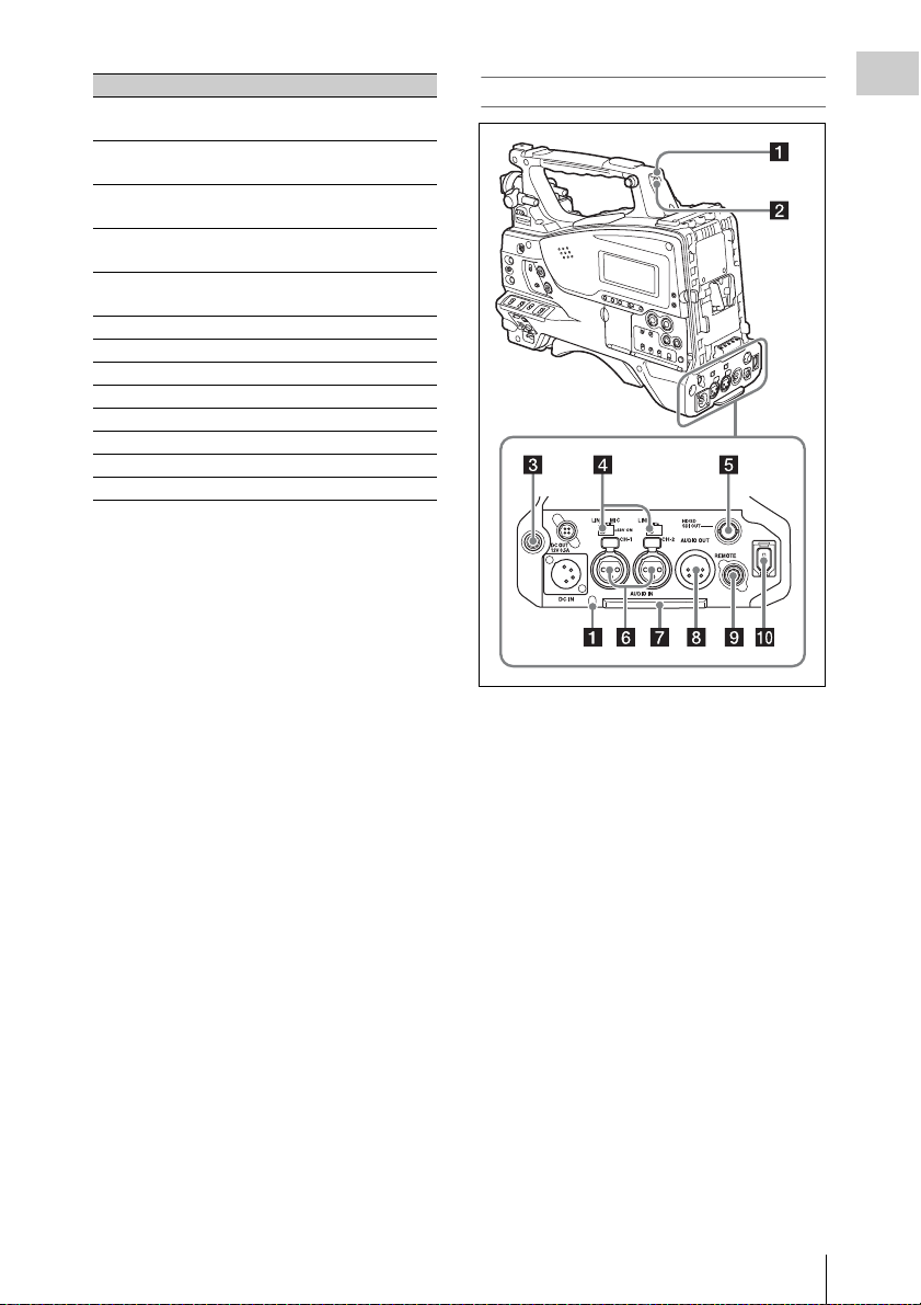
Locations and Functions of Parts and Controls
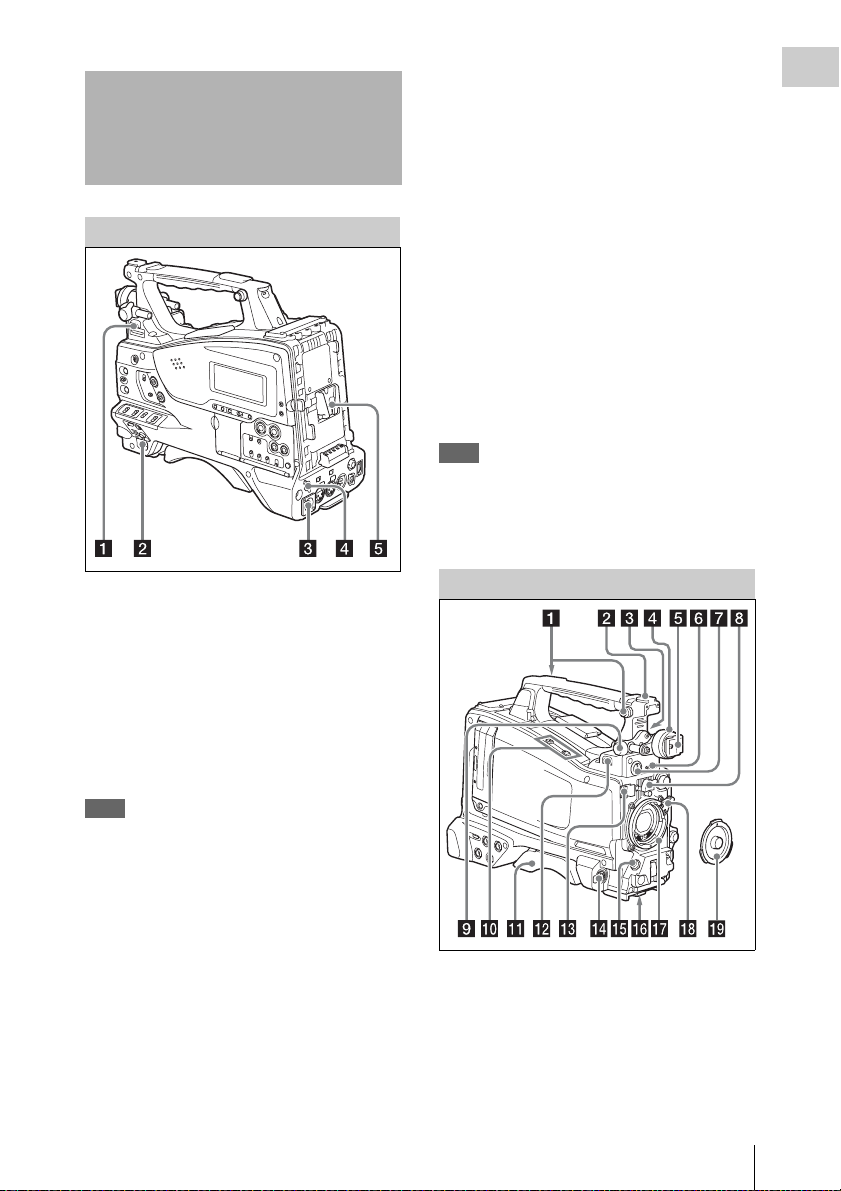
d DC OUT 12V (DC power output)
connector (4-pin, female)
Supplies power for an optional WRR-860A/861/
862 UHF Synthesized Diversity Tuner
(maximum 0.5 A).
Do not connect any equipment other than the
UHF synthesized diversity tuner.
Chapter 1 Overview
Power Supply
a LIGHT switch
Determines how a video light connected to the
LIGHT connector (see page 14) is turned on and
off.
AUTO : When the POWER switch of the video
light is in the on position, the video light is
turned on automatically while the camcorder
is recording.
MANUAL: You can turn the video light on or off
manually, using its own switch.
Note
When the camcorder is set for recording in Picture Cache
mode, it is not possible to turn on the light before
operation to start recording is carried out (or while data
is being stored in memory).
e Battery attachment shoe
Attach a BP-GL95/GL65/L80S/L60S Battery
Pack. Alternatively, you can attach an ACDN2B/DN10 AC Adaptor to operate the
camcorder on AC power supply.
For details, see “Preparing a Power Supply”
(page 32).
For details, see “Attaching a UHF Portable Tuner
(for a UHF Wireless Microphone System)”
(page 43).
Note
For your safety, and to ensure proper operation of the
camcorder, Sony recommends the use of the following
battery packs: BP-GL95, BP-GL65, BP-L60S, and
BP-L80S.
Accessory Attachments
b POWER switch
Turns the main power supply on and off.
c DC IN (DC power input) connector
(XLR type, 4-pin, male)
To operate the camcorder from an AC power
supply, connect an optional DC power cord to this
terminal and then connect the cord to the DC
output terminal of the BC-L70, BC-L160, or
another battery charger.
a Shoulder strap fitting
Attach the supplied shoulder strap (see page 45).
b Accessory fitting shoe
Attach an optional accessory such as a video light
(see page 45).
Locations and Functions of Parts and Controls
13
Page 14

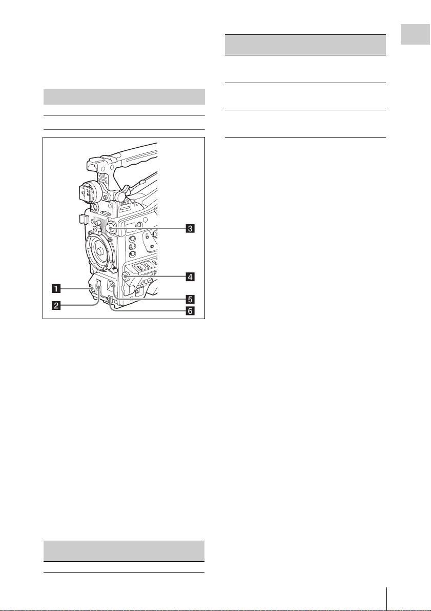
c Viewfinder front-to-back positioning
Chapter 1 Overview
lever
To adjust the viewfinder position in the front-toback direction, loosen this lever and the LOCK
knob. After adjustment, retighten this lever and
the LOCK knob.
l LIGHT (video light) connector (2-pin,
female)
A video light with a maximum power
consumption of 50 W, such as the Anton Bauer
Ultralight 2 or equivalent can be connected (see
page 45).
d Viewfinder left-to-right positioning ring
Loosen this ring to adjust the left-to-right position
of the viewfinder (see page 34).
e Viewfinder fitting shoe
Attach the viewfinder.
f VF (viewfinder) connector (26-pin,
rectangular)
Connect the cable of the supplied viewfinder.
g VF (viewfinder) connector (20-pin,
round)
Connect the cable of the optional DXF-51, DXFC50W or DXF-20W viewfinder.
For connecting the DXF-51 or DXF-C50W, optional
parts are required. Consult a Sony service
representative for information about connecting the
DXF-51 or DXF-C50W.
h Lens mount securing rubber
After locking the lens in position using the lens
locking lever, fit this rubber over the lower of the
two projections. This fixes the lens mount,
preventing it from coming loose.
i Viewfinder front-to-back positioning
knob (LOCK knob)
Loosen this knob to adjust the front-to-back
position of the viewfinder (see page 34).
j Fitting for optional microphone holder
Fit an optional CAC-12 Microphone Holder (see
page 42).
k Shoulder pad
Raise the shoulder pad fixing lever to adjust the
position in the front-to-rear direction. Adjust the
position for maximum convenience when
operating the camcorder on your shoulder (see
page 46).
m Lens cable clamp
Clamp a lens cable.
n MIC IN (microphone input) (+48 V)
connector (XLR type, 5-pin, female)
Connect a stereo microphone to this connector.
The power (+48 V) is supplied via this connector.
o LENS connector (12-pin)
Connect a lens cable to this connector.
This connector is not used for a
which is connected by a hot shoe inside the lens
mount.
Note
When connecting or disconnecting the lens cable to this
connector, power off the camcorder first.
1
/2-inch lens
p Tripod mount
When using the camcorder on a tripod, attach the
tripod adaptor (optional).
q Lens mount (special bayonet mount)
Attach the lens.
On the inner side of the lens mount is a 14-pin
connector (two 7-pin connectors) for connecting
the lens.
Consult a Sony service representative for
information about available lenses.
Note
The auto iris function is not available if the mounted lens
has a 7-pin connector for connection to the camera.
The video level indication and the iris position indication
are also disabled.
r Lens locking lever
After inserting the lens in the lens mount, rotate
the lens mount ring with this lever to lock the lens
in position.
After locking the lens, be sure to use the lens
mount securing rubber to prevent the lens from
becoming detached.
Locations and Functions of Parts and Controls
14
Page 15
s Lens mount cap
Remove by pushing up the lens locking lever.
When no lens is mounted, keep this cap fitted for
protection from dust.
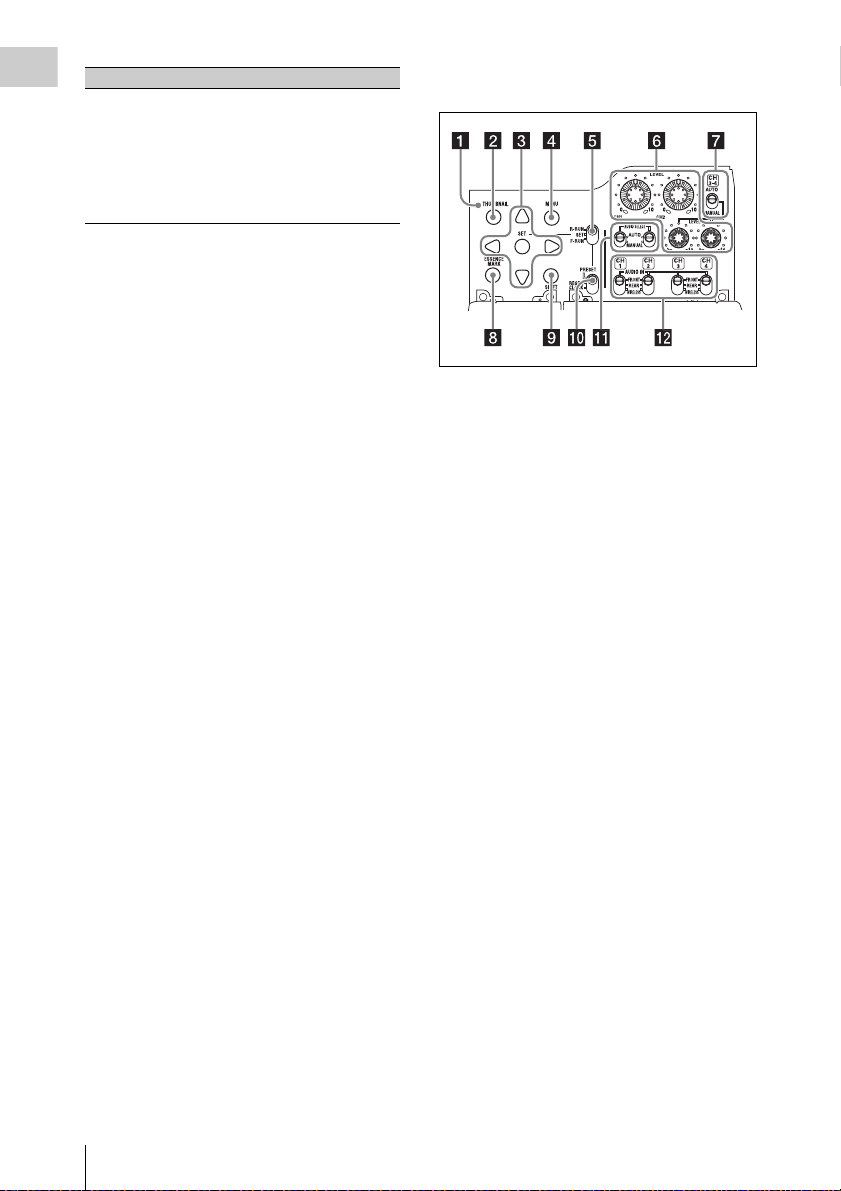
Operating and Connectors Section
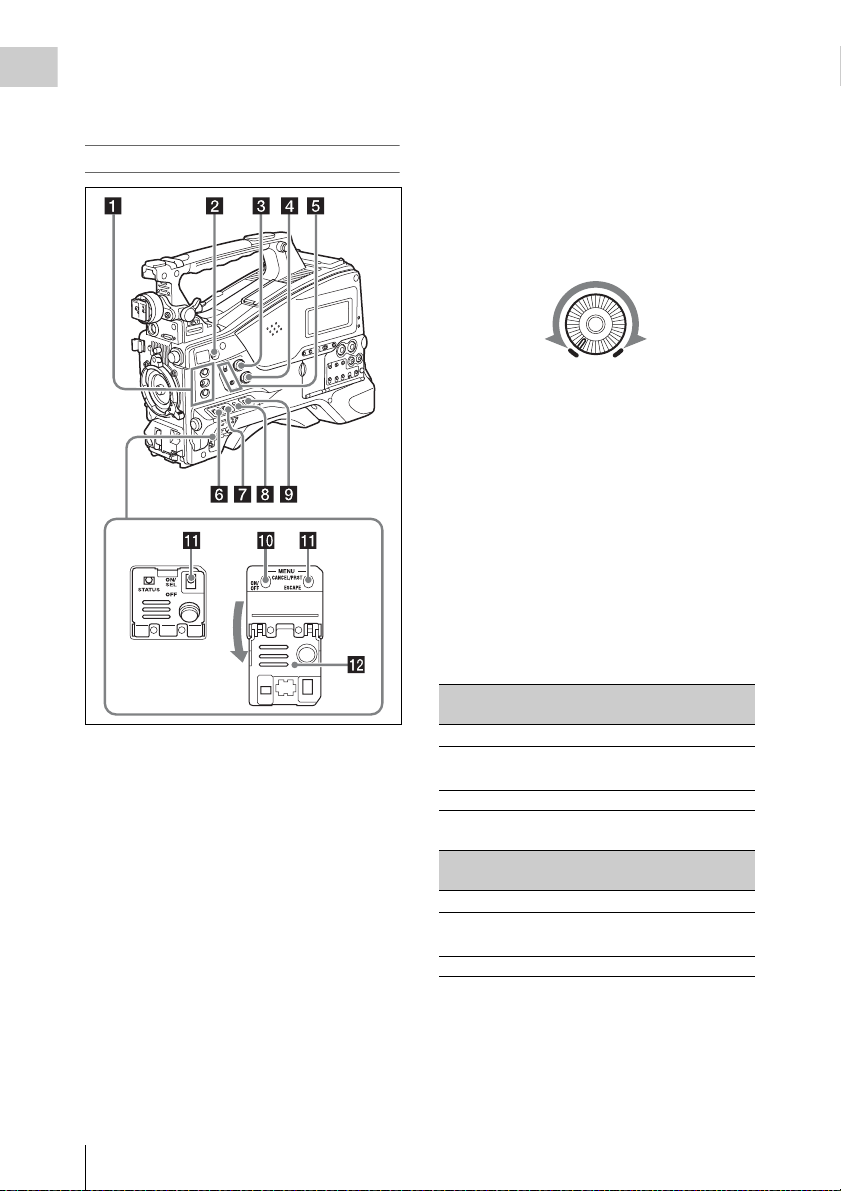
Front
a REC START (recording start) button
Press to start recording. Press it again to stop
recording. The effect is the same as that of the
REC button on the lens.
b SHUTTER selector
Set to ON to use the electronic shutter. Push to
SELECT to switch the shutter speed or shutter
mode setting. When this switch is operated, the
new setting appears on the viewfinder screen for
about three seconds.
For details, see “Setting the Electronic Shutter”
(page 52).
c FILTER selector
Switches between four ND filters built into this
camcorder.
When this selector is used, the new setting
appears on the viewfinder screen for about three
seconds.
FILTER selector
setting
1 CLEAR
ND filter
FILTER selector
setting
2
3
4
ND filter
1
/4 ND (attenuates light to
approximately
1
/16 ND (attenuates light to
approximately
1
/64 ND (attenuates light to
approximately
1
/4)
1
/16)
1
/64)
You can change a MAINTENANCE menu
setting so that different white balance settings can
be stored for different FILTER selector positions.
This allows you to automatically obtain optimum
white balance for the current shooting conditions
in linkage with the filter selection.
For details, see “Adjusting the White Balance”
(page 49).
d MENU knob
Changes the item selection or a setting within the
menu (see page 91).
e AUTO W/B BAL (automatic white/
black balance adjustment) switch
Activates the automatic white/black balance
adjustment functions.
WHITE: Adjust the white balance automatically.
If the WHITE BAL switch (see page 17) is
set to A or B, the white balance setting is
stored in the corresponding memory. If the
WHITE BAL switch is set to PRST, the
automatic white balance adjustment function
does not operate.
BLACK: Adjust the black set and black balance
automatically.
You can use the AUTO W/B BAL switch even
when the ATW (Auto Tracing White Balance)
function is operating.
If you push the switch to the WHITE side once
more during the automatic white balance
adjustment, the adjustment is cancelled and the
white balance setting returns to the original
setting.
If you push the switch to the BLACK side once
more during the automatic black balance
adjustment, the adjustment is cancelled and the
black balance setting returns to the original
setting.
Chapter 1 Overview
Locations and Functions of Parts and Controls
15
Page 16
f MIC (microphone) LEVEL control
Adjusts the input level of audio channels 1, 2, 3
Chapter 1 Overview
and 4 (see page 57).
Right side (near the front)
c ALARM (alarm tone volume
adjustment) knob
Controls the volume of the warning tone that is
output via the built-in speaker or optional
earphones. When the knob is turned to the
minimum position, no sound can be heard.
However, if MAINTENANCE >Audio >Min
Alarm Volume in the setup menu is set to [Set],
the alarm tone is audible even when this volume
control is at the minimum position.
ALARM
Minimum Maximum
d MONITOR (monitor volume
adjustment) knob
Controls the volume of the sound other than the
warning tone that is output via the built-in speaker
or earphones. When the knob is turned to the
minimum position, no sound can be heard.
e MONITOR (audio monitor selection)
switches
By means of combinations of the two switches,
you can select audio that you want to hear through
the built-in speaker or earphones.
a ASSIGN. (assignable) 1/2/3 switches
You can assign the desired functions to these
switches on OPERATION >Assignable SW in
the setup menu (see page 129).
EZ Mode is assigned to the ASSIGN. 1 switch,
and Off is assigned to the ASSIGN. 2/3 switches
as the factory default setting.
The ASSIGN.1/3 switches are provided with an
indicator to show whether a function is assigned
to the switch (ON) or not (OFF).
b COLOR TEMP. (color temperature)
button
Press to light the button and change the color
temperature for shooting (factory default setting).
You can use this as an assignable switch (see
page 129).
Locations and Functions of Parts and Controls
16
Position of down-side switch: CH-1/2
Position of up-side
switch
CH-1/CH-3 Channel 1 audio
MIX Channels 1 and 2 mixed
CH-2/CH-4 Channel 2 audio
Audio outp ut
audio (stereo)
a)
Position of down-side switch: CH-3/4
Position of up-side
switch
CH-1/CH-3 Channel 3 audio
MIX Channels 3 and 4 mixed
CH-2/CH-4 Channel 4 audio
a) By connecting stereo headphones to the EARPHONE
jack, you can hear the audio in stereo. (Under
MAINTENANCE >Audio in the setup menu,
Headphone Out must be set to STEREO.)
Audio outp ut
audio (stereo)
a)
Page 17

f ASSIGN. (assignable) 0 switch
You can assign the desired function to this switch
on OPERATION >Assignable SW in the setup
menu (see page 130).
Off is assigned to this switch when the camcorder
is shipped from the factory.
This is a momentary type switch. Each press of
the switch turns the function assigned to this
switch on or off.
g GAIN selector
Switches the gain of the video amplifier to match
the lighting conditi ons during shooting. The gains
corresponding to the L, M, and H settings can be
selected on OPERATION >Gain Switch in the
setup menu (see page 102). (The factory settings
are L=0 dB, M=6 dB, and H=12 dB.)
When this switch is adjusted, the new setting
appears on the viewfinder screen for about three
seconds.
h OUTPUT/DCC (output signal/dynamic
contrast control) switch
Switches the video signal output from the camera
module, between the following two.
BARS: Output the color bar signal.
CAM: Output the video signal being shot. When
this is selected, you can switch DCC
1)
on and
off.
1) DCC (Dynamic Contrast Control): Against a very
bright background with the iris opening adjusted to the
subject, objects in the background will be lost in the
glare. The DCC function will suppress the high
intensity and restore much of the lost detail and is
particularly effective in the following cases.
• Shooting people in the shade on a sunny day
• Shooting a subject indoors, against a background
through a window
• Any high contrast scene
i WHITE BAL (white balance memory)
switch
Controls adjustment of the white balance.
PRST: Adjust the color temperature to the preset
value (the factory default setting: 3200K).
Use this setting when you have no time to
adjust the white balance.
A or B: Recall the white balance adjustment
settings already stored in A or B. Push the
AUTO W/B BAL switch (see page 15) on
the WHITE side, to automatically adjust the
white balance, and save the adjustment
settings in memory A or memory B.
1)
B (ATW
): When this switch is set to B and
OPERATION >White Setting >White
Switch<B> is set to [ATW] in the setup
menu, ATW is activated.
You can use the AUTO W/B BAL switch
even when ATW is in use.
When this switch is adjusted, the new setting
appears on the viewfinder screen for about three
seconds.
1) ATW (Auto Tracing White Balance): The white
balance of the picture being shot is adjusted
automatically for varying lighting conditions.
j MENU ON/OFF switch
To use this switch, open the cover.
This switch is used to display the menu on the
viewfinder screen or the test signal screen. Each
time the switch is pushed down, the menu screen
is turned on and off.
The function of this switch is the same as that of
the MENU button in the thumbnail screen
operations section.
k STATUS ON/SEL/OFF (menu display
on/page selection/display off) switch
MENU CANCEL/PRST (preset) /
ESCAPE switch
When the menu is not displayed, this switch
functions as the STATUS ON/SEL/OFF switch.
When the menu is displayed, the switch functions
as the MENU CANCEL/PRST/ESCAPE switch.
(To use the MENU CANCEL/PRST/ESCAPE
switch, open the cover.)
Use the STATUS ON/SEL/OFF switch in the
following way.
ON/SEL: Each time this switch is pushed
upward, a window to confirm the menu
settings and status of the camcorder appears
on the viewfinder screen (see page 62). The
window consists of five pages, which are
switched each time the switch is pushed
upward. Each page is displayed for about 10
seconds.
OFF: To clear the page immediately after
display, push this switch down to the OFF
position.
Use the MENU CANCEL/PRST/ESCAPE in the
following way.
Chapter 1 Overview
Locations and Functions of Parts and Controls
17
Page 18
CANCEL/PRST: Pushing this switch up to this
Chapter 1 Overview
position after a setting is changed in the setup
menu displays the message to confirm
whether the previous settings are cancelled.
Pushing this switch up to this position again
cancels the previous settings.
Pushing this switch up to this position before
a setting is changed in the setup menu or after
a setting change is cancelled in the setup
menu displays the message to confirm
whether the setting is reset to the initial
value.
Pushing this switch up to this position again
resets the settings to the initial value.
ESCAPE: Use this switch when the menu page,
which has a hierarchical structure, is opened.
Each time the switch is pushed to this
position, the page returns to one stage higher
in the hierarchy.
l Cover
Open this cover to use the MENU ON/OFF
switch or the MENU CANCEL/PRST/ESCAPE
switch.
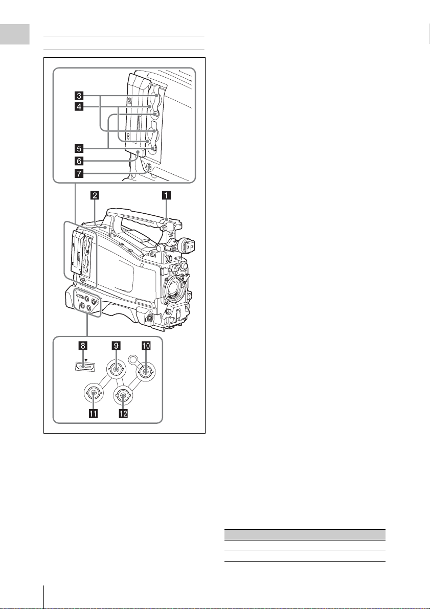
Right side (near the rear)
Locations and Functions of Parts and Controls
18
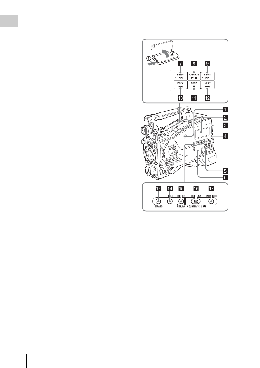
a Built-in speaker
The speaker can be used to monitor E-E1) sound
during recording, and playback sound during
playback. The speaker also sounds alarms to
reinforce visual warnings (see page 147).
If you connect earphones to the EARPHONE
jack, the speaker output is suppressed
automatically.
1) E-E: Abbreviation of “Electric-to-Electric”. In E-E
mode, video and audio signals input to the camcorder
are output after passing through internal electric
circuits only. This can be used to check input signals.
b Monochrome LCD panel
Displays remaining battery capacity, remaining
media capacity, audio levels, time data, and so on
(see page 24).
Page 19

c WARNING indicator
Lights up or flashes when an abnormality occurs
(see page 147).
d ACCESS lamp
Lights up when data is written to or read from the
recording media.
e Protection cover of the audio control
section
Open to access the audio control section (see
page 20).
f Protection cover of the thumbnail
screen operations section
Open to access the thumbnail screen operations
section (see page 20).
g F REV (fast reverse) button and
indicator
This plays back at high speed in the reverse
direction. The playback speed changes in the
order ×4 t ×15 t ×24 with each press of the
button. The indicator lights during high-speed
playback in the reverse direction.
h PLAY/PAUSE button and indicator
Press this button to view play back video images
using the viewfinder screen or the LCD monitor.
The indicator lights during playback.
Press this button again during playback to pause,
outputting a still image. At this time the indicator
flashes at a rate of once per second.
Pressing the F REV or F FWD button during
playback or pause starts high speed playback in
the forward or reverse direction.
i F FWD (fast forward) button and
indicator
This plays back at high speed in the forward
direction. The playback speed changes in the
order ×4 t ×15 t ×24 with each press of the
button. The indicator lights during high-speed
playback in the forward direction.
j PREV button
This jumps to the first frame of the current clip.
If you press this together with the F REV button,
the jump is to the first frame of the first recorded
clip on the recording media.
If you press this button twice in rapid succession,
the jump is to the first frame of the last preceding
clip (or the first frame of the current clip when no
preceding clips exist).
k STOP button
Press this button to stop playback.
l NEXT button
This jumps to the first frame of the next clip.
If you press this together with the F FWD button,
the jump is to the first frame of the last recorded
clip on the recording media.
m EXPAND (expand function) button
If you press this button when the thumbnail
screen is displayed, the duration of the selected
clip is divided into fractions, and the first frame of
each of the divisions is shown in a further
thumbnail display (expand function). For an HD
recorded MP4 clip, its duration is divided into 12.
If an SD recorded AVI clip comprises multiple
files, the divisions are displayed for the individual
files.
For MP4 clips, each time you press this button the
division is repeated. Ho ld down the SHIFT button
and press this button to step back through the
division process.
n HOLD (display hold) button
Pressing this button instan tly freezes the time d ata
displayed in the monochrome LCD panel. (The
timecode generator continues running.) Pressing
this button again releases the hold.
For details of the counter display, see page 24.
o RESET/RETURN button
Resets the value shown in the time counter
display in the monochrome LCD panel.
According to the settings of the PRESET/
REGEN/CLOCK switch (see page 21) and the
F-RUN/SET/R-RUN switch (see page 20), this
button resets the display as follows.
Settings of switches To reset
DISPLAY switch:
COUNTER
DISPLAY switch:
TC
PRESET/REGEN/
CLOCK switch:
PRESET
F-RUN/SET/R-RUN
switch: SET
Counter to 0:00:00:00
Timecode to 00:00:00:00
Chapter 1 Overview
Locations and Functions of Parts and Controls
19
Page 20
Settings of switches To r eset
Chapter 1 Overview
DISPLAY switch:
U-BIT
PRESET/REGEN/
CLOCK switch:
PRESET
F-RUN/SET/R-RUN
switch: SET
a) Of the timecode bits for every frame recorded on the
media, those bits which can be used to record useful
information for the user such as scene number,
shooting place, etc.
For details, see “Setting the Time Data” (page 59).
User bits data
00
This button returns to the previous screen when
pressed during thumbnail screen display, expand
thumbnail screen display, or shot mark thumbnail
screen display.
p DISPLAY switch
This cycles the data displayed in the time counter
display in the monochrome LCD panel through
the sequence COUNTER, TC, and U-BIT (see
page 24).
COUNTER: Display the elapsed recording/
playback time (hours, minutes, seconds,
frames).
TC: Display timecode.
U-BIT: Display user bits data.
q BACKLIGHT button
Turns the backlight of the monochrome LCD on
and off. The backlight of the monochrome LCD
panel will be turned on when the camcorder is
powered on for the first time after shipped from
the factory.
a)
to 00 00 00
Thumbnail screen operations section and audio
control section
a THUMBNAIL indicator
This lights when thumbnail screen is displayed.
b THUMBNAIL button
Press this button to display the thumbnail screen
(see page 78) and to carry out a thumbnail
operation.
Press once more to return to the original display.
c SET (set) button and arrow buttons
Use these buttons to make timecode and user bit
settings, and for thumbnail screen operations (see
page 83).
When the menu is displayed, press this button to
select an item or to confirm the setting change.
d MENU button
Each press of this button turns the setup menu
display on and off.
The function of this button is the same as that of
the MENU ON/OFF switch.
Locations and Functions of Parts and Controls
20
e F-RUN/SET/R-RUN (free run/set/
recording run) switch
Selects the operating mode of the internal
timecode generator. The operating mode is set as
explained below, depending on the position of the
switch.
F-RUN: Timecode keeps advancing, regardless
of whether the camcorder is recording. Use
this setting when synchronizing the timecode
with external timecode.
SET: Sets the timecode or user bits.
R-RUN: Timecode advances only during
recording. Use this setting to have a
consecutive timecode on the recording
media.
Page 21

For details, see “Setting the Timecode” (page 59)
and “Setting the User Bits” (page 60).
f LEVEL CH-1/CH-2/CH-3/CH-4 (audio
channel 1/2/3/4 recording level) knobs
Adjust the audio levels to be recorded on channels
1, 2, 3, and 4 when the AUDIO SELECT CH-1/
CH-2 and AUDIO SELECT CH 3-4 switches are
set to MANUAL.
g AUDIO SELECT CH 3-4 (audio
channel 3/4 adjustment method
selection) switch
Select the audio level adjustment method for each
of audio channels 3 and 4.
AUTO : Automatic adjustment
MANUAL: Manual adjustment
h ESSENCE MARK button
By pressing this button when the thumbnail
display of a clip is on the screen, you can view the
following thumbnail display of the shot-marked
frames of that clip, depending on the item
selected in a list displayed on the screen.
Shot Mark1: Thumbnail display of the frames
marked with Shot Mark 1
Shot Mark2: Thumbnail display of the frames
marked with Shot Mark 2
Shot Mark: Thumbnail display of the frames
marked with either Shot Mark 1 or Shot Mark
2
k AUDIO SELECT CH-1/CH-2 (audio
channel 1/2 adjustment method
selection) switches
Select the audio level adjustment method for each
of audio channels 1 and 2.
AUT O: Automatic adjustment
MANUAL: Manual adjustment
l AUDIO IN CH1/CH2/CH3/CH4 (audio
channel 1/2/3/4 input selection) switches
Select the audio input signals to be recorded on
audio channels 1, 2, 3 and 4.
FRONT: Audio input signals from the
microphone connected to the MIC IN
connector
REAR: Audio input signals from an audio device
connected to the AUDIO IN CH1/CH2
connectors
WIRELESS: Audio input signals from the UHF
portable tuner if it is installed
Chapter 1 Overview
i SHIFT button
Use this in combination with other buttons.
j PRESET/REGEN (regeneration)/
CLOCK switch
Selects the type of timecode to record.
PRESET: Record new timecode on the media.
REGEN: Record timecode continuous with the
existing timecode recorded on the media.
Regardless of the setting of the F-RUN/SET/
R-RUN switch, the camcorder operates in RRUN mode.
CLOCK: Record timecode synchronized to the
internal clock. Regardless of the setting of
the F-RUN/SET/R-RUN switch, the
camcorder operates in F-RUN mode.
Locations and Functions of Parts and Controls
21
Page 22
Left side and upper section
Chapter 1 Overview
H
D
M
I
G
E
N
IN
V
ID
E
O
O
U
T
b USB connector
Used to put this camcorder into USB connection
mode and use it as an external storage device for
a computer. When a computer without
ExpressCard slot is connected to this connector,
every memory card inserted in the camcorder is
recognized as a drive for that computer.
c S×S memory card slots
These two slots (A and B) can receive S×S
memory cards or other recording media (see
page 65).
d ACCESS lamps
Indicate the state of slots A and B (see page 65).
You can check whether the lamps are lit even
when the slot cover is closed.
e EJECT buttons
To remove the recording media from the slot,
press the EJECT button to release the lock, then
press the button once more. This makes the media
come out of the slot partially (see page 66).
f Slot cover
Slide to the left and right to open and close.
g SLOT SELECT (S×S memory card
select) button
When S×S memory cards are loaded in both card
slots A and B, press this button to select the card
L
O
C
K
T
C
IN
T
C
O
U
T
you want to use (see page 66).
h HDMI output connector
Outputs HDMI signals for video monitoring.
When a video monitor provided with an HDMI
signal input connector is connected to this
connector, you can monitor picture being shot
(camera picture) or playback picture.
a ASSIGNABLE 4/5 switches
You can assign the desired functions to these
switches on OPERATION >Assignable SW in
the setup menu (see page 130).
Off is assigned to these switches when the
camcorder is shipped from the factory.
Locations and Functions of Parts and Controls
22
i GENLOCK IN (genlock signal input)
connector (BNC type)
This connector inputs a reference signal when the
camcorder is to be genlocked or when timecode is
to be synchronized with external equipment.
Available reference signals vary de pending on the
current system frequency as shown in the
following table.
System frequency Available reference signals
1080/59.94i 1080/59.94i, 480/59.94i
1080/29.97P 1080/59.94i, 480/59.94i
Page 23
System frequency Available reference signals
1080/23.98P (PsF
output)
1080/23.98P
(Pulldown output)
720/59.94P 1080/59.94i, 720/59.94P,
720/29.97P 1080/59.94i, 720/59.94P,
720/23.98P 1080/59.94i, 720/59.94P,
480/59.94i 1080/59.94i, 480/59.94i
480/29.97P 1080/59.94i, 480/59.94i
1080/50i 1080/50i, 576/50i
1080/25P 1080/50i, 576/50i
720/50P 1080/50i, 720/50P, 576/50i
720/25P 1080/50i, 720/50P, 576/50i
576/50i 1080/50i, 576/50i
576/25P 1080/50i, 576/50i
1080/23.98PsF, 480/59.94i
1080/59.94i, 480/59.94i
480/59.94i
480/59.94i
480/59.94i
(Genlock for the camera module supports
horizontal sync signals only.) Use
MAINTENANCE >GENLOCK in the setup
menu to adjust the genlock H-phase (phase of
horizontal sync signal).
j TC IN (timecode input) connector
(BNC type)
To apply an external lock to the timecode of the
camcorder, input the reference timecode.
For details, see “Setting the Timecode” (page 59).
k VIDEO OUT connector (BNC type)
Outputs video signals for monitoring. The output
signals can be selected either composite video or
HD-Y depending on the setting of OPERATION
>Input/Output >Output&i.LINK in the setup
menu.
l TC OUT (timecode output) connector
(BNC type)
To lock the timecode of an external VTR to the
timecode of this camcorder, connect this
connector to the external VTR’s timecode input
connector.
Rear
a TALLY (back tally) indicators (red)
Light up during recording. They will not light if
the TALLY switch is set to OFF. These indicators
also flash to indicate warnings (see page 19). The
tally indicator on the front of the viewfinder and
the REC indication on the viewfinder screen light
or flash in the same manner.
For details, see “Operation Warnings” (page 147).
b TALLY switch
Set to ON to activate the TALLY indicator
function.
c EARPHONE jack (stereo, minijack)
You can monitor the E-E sound during recording
and playback sound during playback. When an
alarm is indicated, you can hear the alarm sound
through the earphone. Plugging an earphone into
the jack automatically cuts off the built-in
speaker.
You can select monaural or stereo on
MAINTENANCE >Audio in the setup menu.
Chapter 1 Overview
Locations and Functions of Parts and Controls
23
Page 24
d AUDIO IN selectors
Select the audio source you connect to the
Chapter 1 Overview
AUDIO IN CH1/CH2 connectors.
LINE: When connecting a stereo amplifier or
other external audio signal source
MIC: When connecting a microphone that does
not require 48 V power supply
+48V: When connecting a microphone that
requires 48 V power supply
e HD/SD SDI OUT connector (BNC type)
Outputs an HDSDI or SDSDI signal (with
embedded audio). The output from this connector
can be turned on and off with OPERATION
>Input/Output >SDI Output in the setup menu.
f AUDIO IN CH1/CH2 (audio channel 1
and channel 2 input) connectors (XLR
type, 3-pin, female)
These are audio input connectors for channels 1
and 2 to which you can connect audio equipment
or a microphone.
g Bottom cover
This is provided for protecting the cables
connected to the connectors on the rear panel.
By loosening the screws which retain the cover to
the bottom of the camcorder, you can adjust the
position of the cover depending on the size and
shape of the microphone or audio cable plugs.
After adjusting the position, tighten the screws to
secure the cover.
h AUDIO OUT connector (XLR type, 5-
pin, male)
Outputs the audio signals recorded on audio
channels 1 and 2 or audio channels 3 and 4. The
audio signals are selected by the MONITOR
switch.
i REMOTE connector (8-pin)
Connect a remote control unit, which makes it
possible to control the camcorder remotely.
Note
Before connecting/disconnecting the Remote Control
Unit to/from the camcorder, be sure to turn off the
camcorder POWER switch.
j i.LINK (HDV/DV) connector (6-pin,
IEEE1394 compliant, S400)
To input and output HDV /DV streams, connect to
an HDV/DV device.
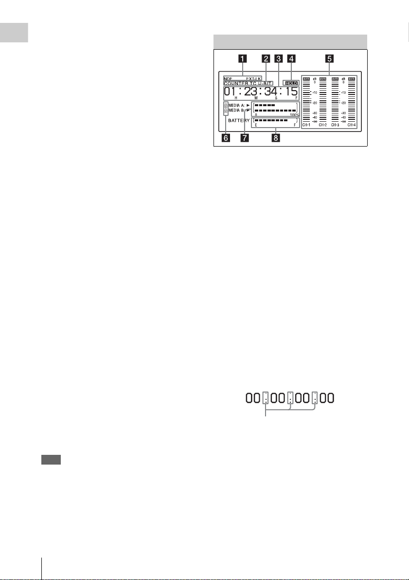
Monochrome LCD Panel
a Timecode status
NDF: Appears when non-drop-frame timecode is
selected.
EXT-LK: Appears when the internal timecode
generator is locked to an external signal input
to the TC IN (timecode input) connector.
b Counter display mode
Shows the type of information selected by the
DISPLAY switch to be displayed in the time
counter display.
COUNTER: Counter values
TC: Timecode
U-BIT: User bits data
c Time counter display
Switches displays of time counter values,
timecode, and user bits data, depending on the
position of the DISPLAY switch.
When the HOLD button is pressed to hold the
timecode value, the timecode is displayed in the
format shown below. When the HOLD button is
pressed again to release the hold, the timecode is
displayed in the normal format.
The three dots indicates that timecode is
displayed in the hold mode.
d HOLD indication
Appears when the timecode generator output is
displayed in the hold mode.
e Audio level indicators
Indicate the audio recording or playback levels of
channels 1 to 4.
Locations and Functions of Parts and Controls
24
Page 25
f Lock icon
Appears when the recording media is writeprotected.
g Remaining media capacity indicator
Shows bar segments indicating the remaining
capacity of recording media in the slots.
h Remaining battery capacity indicator
Shows bar segments indicating the remaining
battery capacity.
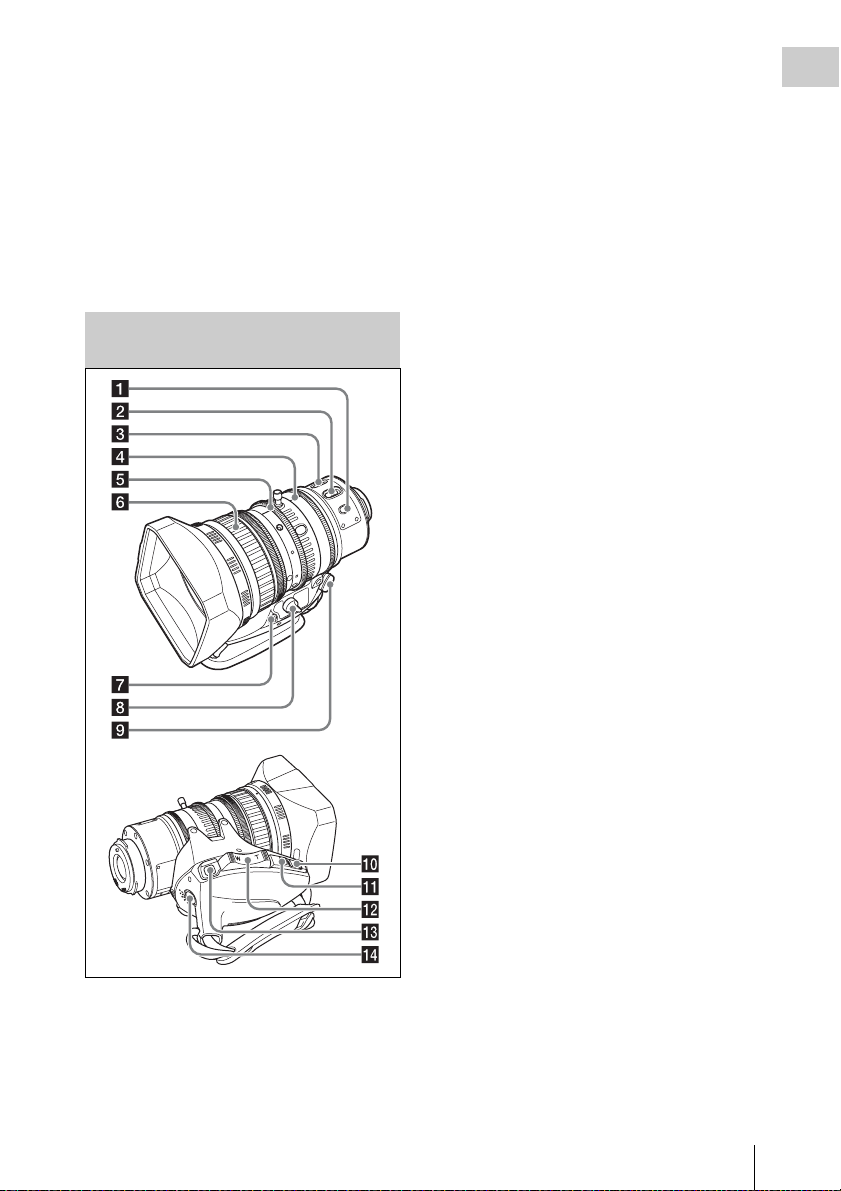
Auto Focus Lens (Supplied with the PMW-320K)
When the button is pressed, the auto focus
operates until the image is in focus, then
disengages.
Even when the FOCUS switch is set to A (auto),
by pressing this button, you can restart the auto
focus.
b FOCUS switch
A (auto): The auto focus function is constantly
active. Even with the switch in the A
position, you can manually adjust the focus
by operating the focus ring.
M (manual): The manual mode allows focusing
adjustment with the focus ring.
In manual mode, auto focus adjustment is also
possible, by pressing the PUSH AF button.
c MACRO switch
When this switch is in the ON position, the macro
mode is enabled, allowing focusing over the
whole range (5 cm
range (from 5 cm
lens).
This operation is independent of whether the
focus adjustment mode is auto or manual.
In the macro range, the auto focusing speed is
lower.
1) At the wide-angle setting
1)
to ∞) including the macro
1)
to 90 cm from the front of the
d Iris ring
For manual iris adjustment, set the IRIS switch to
the M (manual) position, then turn this ring.
Chapter 1 Overview
a PUSH AF (auto focus) button
When the focus adjustment is in the manual
mode, by pressing this b utton you can use the auto
focus for an instantaneous adjustment to the
subject.
e Zoom ring
For manual zoom adjustment, set the ZOOM
switch to the MANUAL position, then turn this
ring.
f Focus ring
Turn this ring to adjust the focus.
This ring can be turned endlessly in both
directions. The faster you turn, the faster the
focusing mechanism operates, to minimize the
amount of turning required for focusing.
When you slide the focus ring back (toward the
camcorder), the focus mode becomes Full MF
mode (see page 56).
g Flange focal length adjustment button
Press this to adjust the flange focal length (the
distance from the lens mounting flange plane to
the focusing plane) (see page 40).
Locations and Functions of Parts and Controls
25
Page 26
h Zoom control connector (8-pin)
Connecting an optional zoom servo controller
Chapter 1 Overview
allows remote control of zooming.
i ZOOM switch
SERVO: Motorized zoom. Operate the zoom
with the power zoom lever.
MANU. (manual): Manual zoom. Operate the
zoom with the zoom ring.
j PUSH AUTO button
When the IRIS switch is in the M position for
manual adjustment, press this button for an
instantaneous auto adjustment.
The iris is automatically adjusted while the button
is held down.
k IRIS switch
A (auto): The iris is adjusted automatically.
M (manual): Adjust the iris with the iris ring.
l Power zoom lever
This is enabled when the ZOOM switch is in the
SERVO position. Press the W end for wide-angle
and the T end for telephoto.
Press the lever harder for a faster zoom action.
Notes on auto focus
• In the following cases, it may be difficult to
focus on the subject. If this does happen, use
manual focusing.
- If the subject has no contrast
- If the subject is moving rapidly
- When shooting point light sources, under
street lighting or at night
- When there are very bright objects close to the
subject
- When shooting through a glass window
• If there are a number of objects within the
screen at close and far range, the focus may not
be on the intended subject. In this case, with the
subject on which you want to focus in the center
of the screen, press the PUSH AF button.
• After focusing with the PUSH AF button, if you
operate the zoom or adjust the iris, the depth of
field may become shallower, losing crisp focus.
In such cases, press the PUSH AF button once
more.
• If you focus at wide-angle then zoom to
telephoto, the subject may no longer be in focus.
• It may take time until the image is in focus
while using the slow shutter mode.
Note on zoom speed
Depending on the shooting distance, the zoom
speed may fall as the lens approaches the
telephoto end.
m RET (return video) button
You can use this as an assignable switch (see
page 132).
Use this to check the video when Lens RET is
assigned to this button (factory default setting). If
you press this during recording pause, the last few
seconds recorded appear on the viewfinder screen
(recording review) (see page 69).
Pressing this button (single click) during
recording or playback records a Shot Mark 1
mark, and double-clicking records a Shot Mark 2
mark (see page 71).
n VTR button
Use this to start and stop recording. Press once to
start recording, then press once more to stop.
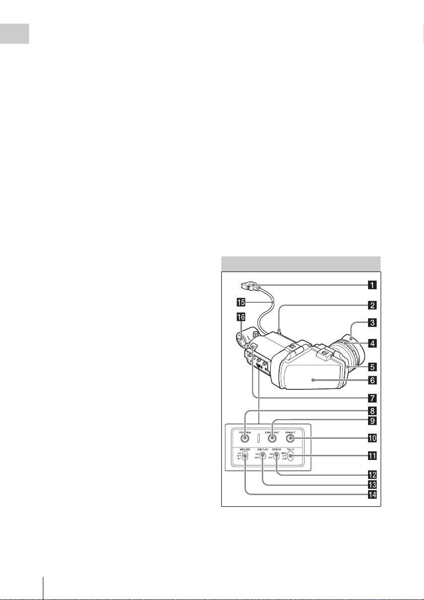
Viewfinder
a Plug
Connect to the VF connector (rectangular) on the
camcorder.
Locations and Functions of Parts and Controls
26
Page 27

b Stopper
Prevents the viewfinder from coming off the
camcorder when it is slid from side to side.
c Eyecup
d Diopter adjustment ring
Allows for optimal focus adjustment.
e Eyepiece
You can raise this up when required by the
situation.
f Viewfinder barrel
You can raise this up or rotate when required by
the situation.
OFF: Do not display a zebra pattern.
m DISPLAY switch
Turns the display of text information on and off.
ON: Display text information.
OFF: Do not display text information.
n MIRROR switch
The image display on the monitor screen becomes
reversed horizontally or vertically when the
viewfinder barrel is raised up or rotated. Use this
switch to control the image display in such
situation.
L/R: Reverse the image horizontally.
OFF: Do not reverse the image.
B/T: Reverse the image vertically.
Chapter 1 Overview
g Tally indicator
Lights up when recording is started by a press of
the REC START button on this camcorder, the
VTR button on the lens, or the VTR button on the
remote control unit.
When an abnormality occurs, the tally indicator
flashes to indicate a warning.
h PEAKING control
Turning this control clockwise adjusts the picture
sharpness, and makes focusing easier. This
control has no effect on the output signals of the
camcorder.
i CONTRAST control
Adjusts the contrast of the screen. This control
has no effect on the output signals of the
camcorder.
j BRIGHT control
Adjusts the brightness of the screen. This control
has no effect on the output signals of the
camcorder.
k TALLY switch
Controls the tally indicator located on the front of
the viewfinder.
HIGH: The tally indicator brightness is set to
high.
OFF: The tally indicator is disabled.
LOW: The tally indicator brightness is set to low.
o Viewfinder cable
p Microphone holder
l ZEBRA (zebra pattern) switch
Controls the zebra pattern display on the
viewfinder screen as follows.
ON: Display a zebra pattern.
Locations and Functions of Parts and Controls
27
Page 28
Chapter 1 Overview
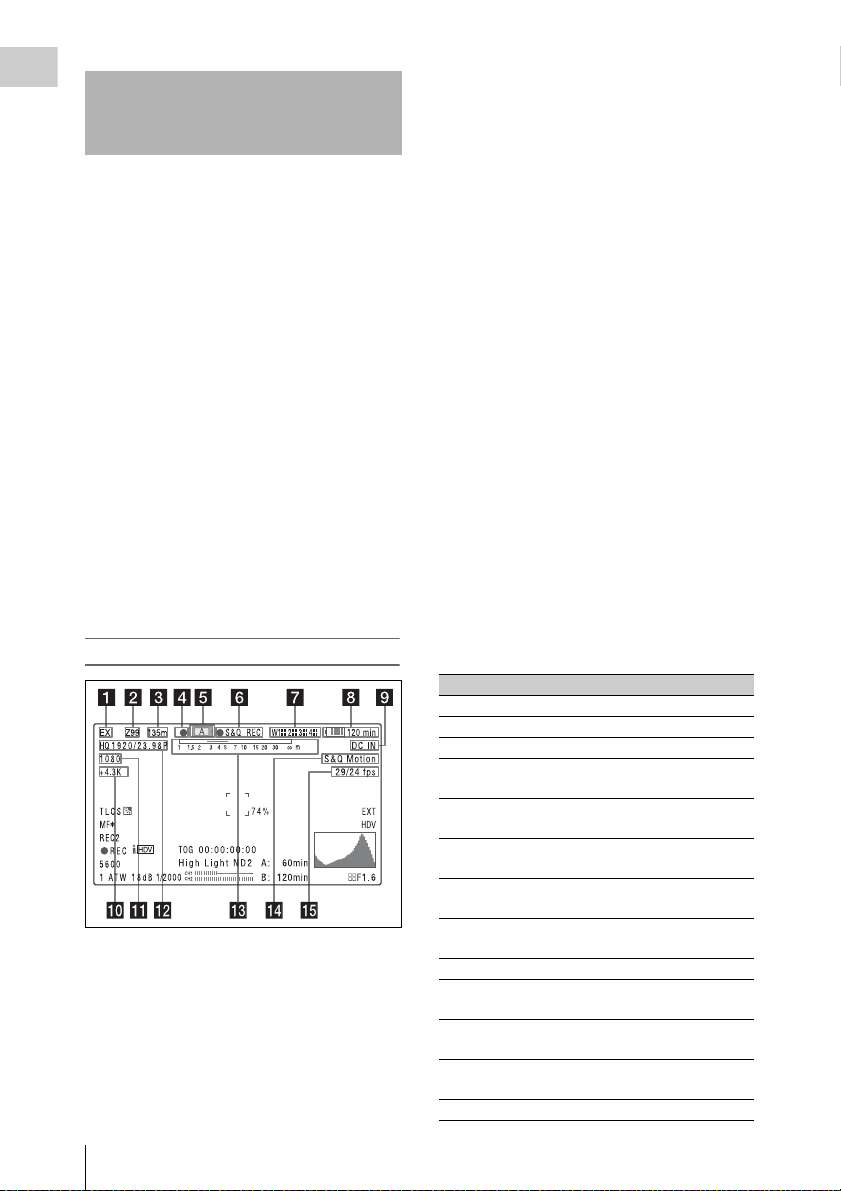
Viewfinder Screen Display
The viewfinder screen displays not only the video
picture but also characters and messages
indicating the camcorder settings and operating
status, a center marker, a safety zone marker, etc.
When the menu screen is not displayed and the
DISPLAY switch is set to ON, the items for
which an ON setting was made with
OPERATION >Super Impose in the setup menu
or with related switches are displayed at the top
and bottom of the screen.
Caution messages are indicated for three seconds
when you carry out operations to change
camcorder settings. Adjustment execution
messages are indicated while adjustments
proceed. When adjustments are finished,
messages showing the results of adjustments
appear for three seconds.
Not only these indications are displayed on the
viewfinder screen, but a menu setting enables
them to be output as video signals.
All items that can be displayed on the viewfinder
screen are shown below.
Top of viewfinder screen
a Extender settings
Indicates the setting of the digital extender
function (by digital extender option) of this
camcorder and the setting of the lens extender.
EX: The lens extender is on.
08: The lens shrinker is on.
x2D: The optional digital extender function of
this camcorder is on.
Ex2D: The lens extender and the optional digital
extender function of this camcorder are both
on.
b Zoom position (when the serial lens is
mounted)
Indicates the zoom position of the zoom lens in
the range from 0 to 99.
c Focus position (when the serial lens is
mounted)
Indicates the focus position as distance to the
subject (in units of m).
d Green tally
Lights when the camcorder is the following
states.
• MAINTENANCE >Camera Config >HD-SDI
Remote I/F is set to [G-Tally] in the setup menu
and a recording control signal is output from the
HD/SD SDI OUT connector.
• When the Picture Cache mode is enabled
e Media status
Displays the name of the currently active media
slot (A or B).
f Recording mode/operation status
Indicates the current recording mode/operation
status as follows.
Indication Meaning
zREC Recording in progress
STBY Standby for recording
zCACHE Standby in Picture Cache mode
zINT REC Recording in progress in Interval
zINT STBY Standby for next recording in
INT STBY Standby in Interval Recording
zFRM REC Recording in progress in Frame
zFRM
STBY
FRM STBY Standby in Frame Recording mode
zS&Q REC Recording in progress in Slow &
S&Q STBY Standby in Slow & Quick Motion
zCALL Being called from a connected
BREVIEW During recording review
Recording mode
Interval Recording mode
mode
Recording mode
Standby for next recording in
Frame Recording mode
Quick Motion mode
mode
device
Viewfinder Screen Display
28
Page 29
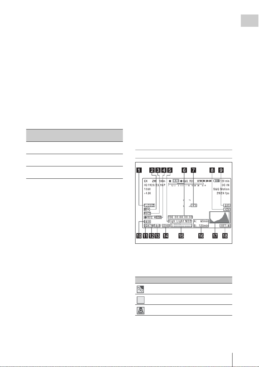
g Wireless receiver reception level
STD
When a wireless receiver is installed in the
camcorder, “W” appears together with four
segment reception level indicators for each of the
channels (1 to 4) that can be used by the receiver.
The indications are as follows.
In normal situation: The number of white
segments indicates the strength of the signal
level.
Muting (for an analog receiver) or error rate
aggravation (for a digital receiver): The
number of gray segments indicates the
strength of the signal level.
h Battery remaining/voltage capacity
The following is displayed depending on the type
of power source.
Type of pow er
source
InfoLithium
battery
Anton Bauer
battery
Other type than
above
What is displayed
Remaining battery capacity icon
and remaining recording time
Remaining battery capacity (%
indication)
Input voltage
i External power input
Appears when power is supplied from an external
power source connected to the DC IN connector.
m Depth of field indication (when the
serial lens is mounted)
Error/warning indication
A bar indicates the depth of field. The display unit
is meters or feet, as selected by OPERATION
>Display On/Off >Lens Info in the setup menu.
An error or warning message is displayed here
depending on the situation.
n Special recording mode indication
The following is displayed when the camcorder is
in a special recording mode.
• Frame Rec (Frame Recording mode)
• Interval Rec (Interval Recording mode)
• S&Q Motion (Slow & Quick Motion mode)
o Special recording mode settings
indication
Appears when the camcorder is in a special
recording mode.
Bottom of viewfinder screen
Chapter 1 Overview
j Color temperature
Displays a color temperature calculated from the
gain of R and B, in the range 1.5 K to 50.0 K (in
steps of 0.1 K). The +/– signs may be displayed
depending on the Offset White setting (see
page 90).
No display: Offset White is OFF
+: The value of Offset White is greater than
3200K.
–: The value of Offset White is less than 3200K.
k Number of system lines
Indicates the number of system lines (1080/720/
576/480) of video currently being recorded or
played back.
l Video format
Indicates the format of video being currently
played back or recorded (see page 47).
The video aspect ratio (16:9 or 4:3) can also be
displayed when the recording format is set to
DVCAM.
a TLCS iris control mode
The following icons are displayed to indicate the
video level control modes based on the Total
Level Control System (TLCS).
Icon TLCS control mode
Backlight mode
STD
Standard mode
Spotlight mode
b Focus adjustment mode (when the auto
focus lens is mounted)
Indicates the current focus adjustment mode of
the camcorder.
Viewfinder Screen Display
29
Page 30
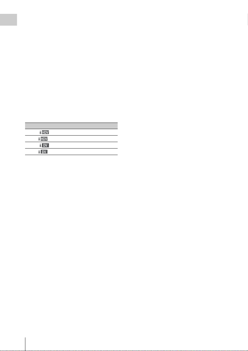
• AF (Auto Focus mode)
• MF (Manual Focus mode)
Chapter 1 Overview
• MF* (Manual Focus mode when the MF Assist
function is on)
• Full MF (Full Manual Focus mode)
c External device control
“REC2” is displayed when MAINTENANCE
>Camera Config >HD-SDI Remote I/F is set to
[Chara] in the setup menu and a recording control
signal is output from the HD/SD SDI OUT
connector.
d Operation status of connected i.LINK
device
The operating format (HDV or DV) and operation
status of that device are indicated as follows.
Indication Meaning
zREC
STBY
zREC
STBY
HDV recording in progress
Standby for HDV recording
DV recording in progress
Standby for DV recording
e Video level indication
An indication is displayed together with an
appropriate ND filter position number when the
light level of the subject is too high or too low.
f Timecode
Caution message
Indicates the elapsed recording/playback time,
timecode, user bits data or other information
selected by the DISPLAY switch (see page 20).
Also indicates a caution message when caution is
required such as when you try to change settings.
g Brightness level
Indicates the average brightness level (%) of the
detection area.
h External input source
Indicates the type of external input signal (HDV)
to be recorded.
i Recording of external input
Indicates “EXT” when an external input is
recorded.
j Electric color temperature filter
Appears when the CC 5600K function is set to on.
k Filter position
Indicates the currently selected ND filter position
number. (see page 15).
When ELECTRICAL CC is assigned to an
assignable switch, the electrical filter position (A/
B/C/D) appears to the right of the ND filter
position (1 to 4), as shown on the previous page.
l White balance memory
Indicates the currently selected white balance
automatic adjustment memory.
AT W: ATW (Auto Tracing White Balance) mode
W:A : Memory A mode
W:B : Memory B mode
W:P : Preset mode
3200: When the assignable switch to which Color
Temp SW 3200K has been assigned is on
4300: When the assignable switch to which Color
Temp SW 4300K has been assigned is on
5600: When the assignable switch to which Color
Temp SW 5600K has been assigned is on
6300: When the assignable switch to which Color
Temp SW 6300K has been assigned is on
m Gain value
Indicates the gain value (in dB) of the video
amplifier, as set by the GAIN selector.
n Shutter
Indicates the shutter speed or the shutter mode.
For details, see “Setting the Electronic Shutter”
(page 52).
o Audio level meters
Indicate the audio levels of channel 1 and channel
2.
p Remaining media capacity
Indicates the recordi ng time remaining for each of
the media loaded in the slots. The available time
for recording with the current video format
(recording bit rate) is calculated according to the
remaining space of each media and indicated in
time units of minutes. A lock icon appears if the
media is write-protected.
q Histogram
Shows a pixel distribution of video luminance
(HD mode only).
Viewfinder Screen Display
30
Page 31

r Iris position (when the lens is mounted)
Indicates the iris position and the setting for iris
override (reference value for the lens iris) (see
page 54).
The iris override setting is indicated by four
segments indicator as follows.
Reference
value
+0.25
+0.5 xxLeft two segments are lit in grey.
Indicator
Lower left segment is lit in grey.
x
Chapter 1 Overview
+0.75 xxxLeft two segments and lower
+1 xxxxAll segments are lit in grey.
–0.25
–0.5 ssLeft two segments are lit in
–0.75 sssLeft two segments and lower
–1 ssssAll segments are lit in white.
right segment are lit in grey.
Lower left segment is lit in
s
white.
white.
right segment are lit in white.
Viewfinder Screen Display
31
Page 32

Chapter2 Preparations
Preparing a Power
Chapter 2 Preparations
Supply
Note on using the battery pack
A warm battery pack may not be able to be fully
recharged.
To attach the battery pack
For safety, use only the Sony battery packs and
AC adaptors listed below.
• BP-GL95/GL65/L60S/L80S Lithium-ion
Battery Pack
• AC power using the AC-DN2B/DN10 AC
Adaptor
CAUTION
Danger of explosion if battery is incorrectly replaced.
Replace only with the same or equivalent type
recommended by the manufacturer.
When you dispose of the battery, you must obey the law
in the relative area or country.
Using a Battery Pack
When a BP-GL95/GL65/L60S/L80S Battery
Pack is used, the camcorder will operate
continuously for the time shown below.
Model name Operating time
BP-GL95 Approx. 310 minutes
BP-GL65 Approx. 210 minutes
BP-L60S Approx. 210 minutes
BP-L80S Approx. 270 minutes
WARNING
Batteries shall not be exposed to excessive heat such as
sunshine, fire or the like.
Note
The battery pack operating time depends on the
frequency of use of the battery pack, and the ambient
temperature when used.
1 Press the battery pack against the back
of the camcorder, aligning the line on
the side of the battery pack with the
matching line on the camcorder.
1 BP-GL95/GL65/L60S/L80S
2 Align these lines.
2 Slide the battery pack down until its
“LOCK” arrow points at the matching
line on the camcorder.
Before use, charge the battery pack with a charger
suitable for each battery.
For details on the battery charging procedure, refer
to the battery charger operation manual.
Preparing a Power Supply
32
1 “LOCK” arrow
2 Matching line on the camcorder
Page 33

Note
If the battery pack is not attached correctly, the terminal
may be damaged.
To detach the battery pack
Holding the release button in, pull the battery
pack up.
Release button
Notes
• During recording and playback (while the ACCESS
indicator is lit), be careful never to remove the battery
pack.
• Make sure to power the camcorder off before replacing
the battery pack.
Using AC Power
Mount an AC-DN2B/DN10 on the camcorder in
the same way as a battery pack, then connect to
the AC power supply.
The AC-DN2B/DN10 can supply up to 100 W of
power.
Attaching the Viewfinder
CAUTION
When the viewfinder is attached, do not leave the
camcorder with the eyepiece facing the sun.
Direct sunlight can enter through the eyepiece, be
focused in the viewfinder and cause fire.
Attaching the Supplied Viewfinder
Note
When attaching the viewfinder, make notes of the
following points.
• Be sure to power off the camcorder before coupli ng the
viewfinder connector to the camcorder’s VF connector
(rectangular). If you make this connection when the
camcorder power is on, the viewfinder may not
function properly.
• Couple the viewfinder connector firmly to the
camcorder’s VF connector (rectangular). If the
coupling is loose, noise may appear on the video or the
tally indicator may not operate properly.
1 1 Loosen the viewfinder left-to-right
positioning ring, 2 attach the
viewfinder to the viewfinder fitting
shoe, and 3 tighten the viewfinder leftto-right positioning ring.
Stopper
Viewfinder leftto-right
positioning ring
Chapter 2 Preparations
To an AC outlet
Attaching the Viewfinder
33
Page 34

2 Couple the viewfinder connector to the
VF connector (rectangular).
VF connector (rectangular)
Chapter 2 Preparations
Detaching the viewfinder
You can detach the viewfinder by following the
attaching procedure in reverse order, but there is
an additional action to take: when detaching the
viewfinder from the fitting shoe, pull up the
stopper.
Adjusting the Viewfinder Position
To adjust the viewfinder left-to-right position,
loosen the left-to-right positioning ring, and to
adjust the front-to-back position, loosen the frontto-back positioning knob.
Viewfinder left-to-right positioning ring
Adjusting the Viewfinder Angle
You can adjust the angle of the viewfinder.
To reverse the display (image/text indication)
vertically
The viewfinder can be rotated as much as 180
degrees toward the direction facing the subject.
When you do this, the picture and other
information displayed in the viewfinder appear
upside down. To restore the normal display, set
the MIRROR switch on the rear panel of the
viewfinder to B/T.
Lifting Up the Viewfinder Barrel and Eyepiece
You can view the LCD screen inside the
viewfinder or its mirrored image by lifting up the
viewfinder barrel or the eyepiece.
This section describes how to lift up the
viewfinder barrel and detach it. The eyepiece can
also be lifted up and detached in the same way.
Viewfinder front-to-back positioning knob
Attaching the Viewfinder
34
LCD screen
Page 35

To raise up the viewfinder barrel
Push the clip on the bottom to release (1) and
flip up the viewfinder barrel (2).
It locks at the 120-degree position.
Normally use it in the locked position.
Although you can open it farther from the lock
position, once return it to the closed position to
lock it at the 120-degree position again.
To detach the viewfinder barrel
Chapter 2 Preparations
1 Push the clip on the bottom to release.
2 Flip up the viewfinder barrel.
3 Slide the knob on the top to the opposite
side of the viewfinder barrel.
4 Detach the viewfinder barrel by
horizontally sliding it.
To reverse the display (image/text indication)
horizontally
By setting the MIRROR switch on the rear panel
of the viewfinder to L/R, you can reverse the
picture and other information displayed in the
viewfinder horizontally.
Attaching the Viewfinder
35
Page 36

Adjusting the Viewfinder Focus and Screen
To adjust the viewfinder focus
Turn the diopter adjustment ring until the
viewfinder image is sharpest.
Chapter 2 Preparations
1 Loosen the front-to-back viewfinder
positioning levers and the front-to-back
viewfinder positioning knobs, and then
pull the viewfinder slide assembly
forward.
2 Using a 2.5 mm diameter hexagonal
wrench, detach the viewfinder slide
assembly.
Diopter adjustment ring
To adjust the viewfinder screen
Adjust the brightness, con trast, and peaking of the
viewfinder screen with the controls shown below.
1 PEAKING control
2 CONTRAST control
3 BRIGHT control
Using the BKW-401 Viewfinder Rotation Bracket
By fitting an optional BKW-401 Viewfinder
Rotation Bracket, you can rotate the viewfinder
out of the way so that your right leg does not hit
the viewfinder while you are carrying the
camcorder.
Bolts with
hexagonal
hole
Viewfinder slide assembly
3 Attach the BKW-401 with the supplied
bolts.
Bolts supplied with the BKW-401
Attaching the Viewfinder
36
Page 37

4 Adjust the front-to-back position so
that the arm of the BKW-401 does not
touch the handle when it is raised.
Adjust position so that arm
does not touch handle
Attaching a 5-inch Electronic Viewfinder
You can attach an optional DXF-51or DXF-C50W (5-inch) Electronic Viewfinder. To attach it, an
Accessory Shoe Kit (service part number: A-8274-968-B) is required.
For details, consult a Sony service representative.
Note
It is not possible to use the supplied viewfinder and a 5-inch viewfinder at the same time.
Remove the cover of the grip, and attach the shoe and stopper screw of the Accessory Shoe Kit.
Fixing ring
VF cable
Guide plate
Chapter 2 Preparations
a) Supplied with the Accessory Shoe Kit
a)
Shoe
Stopper screw
Attaching the Viewfinder
a)
37
Page 38

Setting the Area of Use
Chapter 2 Preparations
When using the camcorder for the first
time
The area of use is not factory preset. Before using
the camcorder, you need to set this item. (You
cannot use the camcorder without setting this
item.)
To set the area of use
POWER switch
MENU knob
1 Set the POWER switch to the ON
position.
The screen for setting the area of use appears
in the viewfinder.
2 Press the MENU knob.
The settings for selectable areas of use are
displayed.
3 Turn the MENU knob to select the
desired area of use.
Setting Area of use
NTSC Area NTSC area (for areas other
than Japan)
NTSC(J) Area
PAL Area
a) The composite signal output from this camcorder
is an NTSC signal with a black setup (7.5 IRE).
The system frequency is 59.94i.
b) The composite signal output from this camcor der
is an NTSC signal with no black setup. The
system frequency is 59.94i.
c) The composite signal output from this camcorder
is a PAL signal. The system frequency is 50i.
NTSC area (Japan)
PAL area
a)
b)
c)
4 Set the following items.
•Time Zone
• Date/Time
See “Basic Setup Menu Operations” (page 91).
Setting the Area of Use
38
5 Turn the MENU knob to select
“Finish”, then press the MENU knob.
The camcorder is now ready for use.
Page 39

Setting the Date/Time of the Internal Clock
Mounting and Adjusting the Lens
You can set or change the date and time of the
internal clock. The date and time set are reflected
in the timecode.
For menu operations, see “Basic Setup Menu
Operations” (page 91).
1 Select MAINTENANCE >Clock Set
>Date/Time in the setup menu.
2 Press the MENU knob.
The Date/Time setting window appears.
Note
Always power the camcorder off before mounting or
removing a lens.
For information about using the lens, refer to the
operation manual for the lens.
Lens mount
securing rubber
Chapter 2 Preparations
3 Turn the MENU knob to display the
desired value, and press the knob.
The selection shifts to the next item on the
right.
4 To continue the remaining settings,
repeat step 3.
5 Making sure that “SET” is selected,
press the MENU knob.
The internal clock is set with the date and
time set in steps 3 and 4.
To cancel the setting
Before executing step 5, push the MENU
CANCEL/PRST/ESCAPE switch up to the
CANCEL/PRST side.
Setting the Date/Time of the Internal Clock / Mounting and Adjusting the Lens
1 Push the lens locking lever up and
remove the lens mount cap from the
lens mount.
2 Align the center pin on the lens with the
center slot in the lens mount, and insert
the lens into the mount.
3 Holding the lens in place, push the lens
locking lever down to lock the lens.
Caution
If the lens is not firmly locked, it may come off
while the camcorder is being used. This could
cause a serious accident. Make sure the lens is
firmly locked. It is recommended that the lens
39
Page 40

mount securing rubber be put on the lens locking
lever as illustrated above.
If you have attached an aberration correction
lens
The aberration correction function is activated
automatically. Starting the camcorder with an
aberration correction lens may require more time
Chapter 2 Preparations
than normally because of data loading at start-up.
The lens supplied with the PMW-320K is an
aberration correction lens. Contact a Sony service
representative for information about other
aberration correction lenses.
Adjusting the Flange Focal Length
If the lens does not stay in focus properly as you
zoom from telephoto to wide angle, adjust the
flange focal length (the distance from the plane of
the lens mounting flange to the imaging plane).
Make this adjustment just one time after
mounting or changing the lens.
When carrying out the adjustment, use the
supplied flange focal length adjustment chart as
the subject.
1 Open the iris, position the supplied
flange focal length adjustment chart
approximately 3 meters (10 ft) away
from the camcorder, and arrange the
lighting to obtain a satisfactory video
output.
2 Set the ZOOM switch to SERVO
(power zoom mode).
3 Hold down the flange focal length
adjustment button for 3 seconds.
The flange focal length adjustment starts.
During adjustment
The message “AUTO FB Adjust
EXECUTING” appears on the viewfinder
screen.
If the adjustment completes correctly
The message on the viewfinder screen
changes to “Auto FB Adjust: OK”.
If the flange focal length adjustment does
not complete correctly
Check the subject and lighting conditions,
and repeat the adjustment.
When using a non-auto focus lens
1 Set the iris to manual.
About 3 m (10 ft)
Notes
• If you use a subject with insufficient contrast, or move
the camcorder or subject during adjustment, this will
cause an adjustment error.
• Place the subject (the flange focal length adjustment
chart) so that it appears at the center of the screen at the
telephoto end. Arrange so that no nearby object (no
object closer to the camera than the chart) enters the
screen at the wide-angle end.
Carrying out the adjustment
When using the auto focus lens
With the lens supplied with the PMW-320K,
zoom and focus operations automatically adjust
the flange focal length.
Mounting and Adjusting the Lens
40
2 Open the iris, position the supplied
flange focal length adjustment chart
approximately 3 meters (10 ft) away
from the camcorder, and arrange the
lighting to obtain a satisfactory video
output.
3 Loosen the fixing screws on the F.f or
F.B ring (flange focal length adjustment
ring).
4 Use manual or power zoom to set the
lens to telephoto.
5 Point the camcorder at the chart by
turning the focus ring and focus on it.
6 Set the zoom ring to wide angle.
7 Turn the F.f or F.B ring until the chart
is in focus, being careful not to disturb
the focus ring.
Page 41

8 Repeat steps 4 to 7 until the chart stays
in focus all the way from wide angle to
telephoto.
9 Tighten the F.f or F.B ring fixing
screws.
Preparing the Audio Input System
Chapter 2 Preparations
Connecting a Microphone to the MIC IN Connector
Attach the supplied microphone to the
microphone holder of the supplied viewfinder.
1 Loosen the screw (1) and open the
microphone holder clamp (2).
Microphone holder clamp
2 Place the microphone in the
microphone holder.
1 Place the microphone in the holder so
that “UP” is at the top.
2 Close the microphone holder.
3 Tighten the screw.
3 Plug the microphone cable into the MIC
IN connector, then set the AUDIO IN
CH1/CH2/CH3/CH4 switch for the
Preparing the Audio Input System
41
Page 42

channel on which you want to record
the audio from this microphone to
FRONT.
Chapter 2 Preparations
4 Secure the microphone cable with the
cable clamp.
Connecting Microphones to the AUDIO IN Connectors
You can connect up to two monaural
microphones to the AUDIO IN CH1/CH2
connectors, using an optional CAC-12
Microphone Holder.
The following is the procedure for attaching an
electret condenser microphone such as the ECM674/678.
On how to attach the CAC-12, refer to the operation
manual for the CAC-12.
1 Attach the electret condenser
microphone.
1 Loosen the ball joint lock lever.
2 Wind the microphone spacer (sheet
type, supplied with the microphone)
around the microphone, while peeling
off the protective sheets on both sides
of the microphone spacer.
3 Place the microphone in the holder so
that “UP” is at the top.
4 Close the microphone holder.
5 Tighten the screw.
6 Position so that the microphone does
not interfere with the viewfinder and
tighten the ball joint lock lever.
Microphone
2 Connect the microphone cable to the
AUDIO IN CH1 or CH2 connector.
3 Set the switches as follows.
• Set the AUDIO IN selectors indicated
below, depending on the power supply type
of the microphone.
Internal power supply: MIC
External power supply: +48V
• Set the AUDIO IN CH1/CH2 swit ch for the
channel to which the microphone is
connected to REAR.
Preparing the Audio Input System
42
Page 43

1 AUDIO IN selectors
2 Monaural microphone
3 AUDIO IN CH1/CH2 switches
4 To AUDIO IN CH1 or CH2 connector
4 Switch the input level to match the
sensitivity of the microphone used.
Switch the input level by changing the setting of
MAINTENANCE >Audio >Rear MIC CH1/
CH2 Ref in the setup menu (factory default
setting is –60 dB). For details, see page 116.
Notes
• If the input level on the camcorder is not at an
appropriate setting for the microphone se nsitivity, loud
sounds may be distorted, and the signal-to-noise ratio
may be affected.
• In order for the AUDIO IN CH1 and CH2 connectors
on the camcorder to be able to provide a phantom 48 V
power supply, female XLR connectors (3-pin) are
fitted. If the microphone cable has a female connector,
use an adaptor.
• When you detach a CAC-12 Microphone Holder once
you have attached to the camcorder, be careful not to
lose the two screws fixing the CAC-12 (in step 1).
After detaching the CAC-12, be sure to put the two
screws back into their original places.
Attaching a UHF Portable Tuner (for a UHF Wireless Microphone System)
For details of these units, refer to the operation
manuals for them.
Note
The optional WRR Mount Bracket (service part number:
A-8278-057-B) is required to fit the WRR-862.
For details, contact your vendor or a Sony service
representative
To fit the DWR-S01D or WRR-855S
1 Remove the four fixing screws holding
the cover of the portable tuner/receiver
housing slot located in the rear of the
camcorder, to remove the cover.
2 Insert the DWR-S01D or WRR-855S
into the housing slot, and fasten the four
fixing screws.
DWR-S01D or WRR-855S
3 Set the AUDIO IN selector for the
channel to which you want to input
audio signal to WIRELESS (see
page 21).
Chapter 2 Preparations
To use a Sony UHF wireless microphone system,
power the camcorder off and then fit one of the
following UHF portable tuners.
• DWR-S01D Digital Wireless Receiver
• WRR-855S UHF Synthesized Tuner Unit
• WRR-860A/861/862 UHF Synthesized
Diversity Tuner
Preparing the Audio Input System
43
Page 44

Tripod Mounting
Chapter 2 Preparations
1 Attach the optional VCT-14/U14
Tripod Adaptor to the tripod.
Tripod adaptor
2 Mount the camcorder on the tripod
adaptor.
Red button
Lever
Note
The tripod adaptor pin may remain in the engaged
position even after the camcorder is removed. If this
happens, press the red button and move the lever as
shown above until the pin returns to the stowed position.
If the pin remains in the engaged position, you will not
be able to mount the camcorder on the tripod adaptor.
Camera mount
Slide the camcorder forward along the
groove in the adaptor until it clicks.
To remove the camcorder from the tripod
adaptor
Hold down the red button and pull the lever in the
direction of the arrow.
Tripod Mounting
44
Page 45

Connecting a Video Light
Using the Shoulder Strap
With this camcorder, you can use the Anton
Bauer Ultralight 2 or equivalent video light
(powered by 12 V with maximum power
consumption of 50 W).
• If you connect the video light to the LIGHT
connector on the camcorder and set the LIGHT
switch to AUTO, you can turn the light on and
off automatically a s you start and stop recording
on this camcorder.
• The output of the LIGHT connector on the
camcorder is controlled to 12 V even when the
camcorder is supplied with over 12 V power
(through the DC IN connector or battery pack).
The brightness or color temperature of the light
will not change according to voltage increase.
Notes
• Do not use a video light with power consumption of
over 50 W.
• The brightness or color temperature of the light will
change when the voltage (supplied through the DC IN
connector or from the battery pack) is under 12 V.
To attach the video light
Fit the video light to the accessory fitting shoe on
the camcorder grip, and connect the video light
cable to the LIGHT connector.
Note
The accessory fitting shoe on the camcorder is of the
1
/4-inch tapped hole type. If you want to replace this with
a slide-type shoe, use the supplied cold shoe kit. On how
to fit the cold shoe kit, refer to “Using a External Hard
Disk” in the Supplement supplied in the CD-ROM
(labeled “Manuals for Solid-State Memory
Camcorder”).
Chapter 2 Preparations
To attach the shoulder strap
1 Fit one of the clips to a shoulder strap
fitting.
Pull up the strap to lock the fitting.
Clip
2 Fit the other clip to the shoulder strap
fitting on the other side of the grip in the
same way as in step 1.
Connecting a Video Light / Using the Shoulder Strap
45
Page 46

To remove the shoulder strap
Press here and pull in the direction
shown by the arrow to release.
Adjusting the Shoulder Pad Position
Chapter 2 Preparations
You can slide the shoulder pad back and forth
within a 40 mm range. This adjustment helps you
get the best balance for shooting with the
camcorder on your shoulder.
Shoulder pad
1 Raise the lever in the center of the
shoulder pad to unlock the shoulder
pad.
2 Slide the shoulder pad backward or
forward until it is in the most
convenient position.
Adjusting the Shoulder Pad Position
46
3 Bring down the lever to lock the
shoulder pad in the selected position.
Page 47

Chapter3 Adjustments and Settings
For menu operations, see “Basic Setup Menu Operations” (page 91).
Setting the Video Format
The following recording formats can be selected for different combinations of video resolution and system
frequency.
OPERATION >Format menu settings Video format (recording
HD/SD System Line Rec Format
HD 1080 HQ 1920 59.94i HQ 1920/59.94i 1920×1080
HQ 1440 59.94i HQ 1440/59.94i 1440×1080
SP 1440 59.94i SP 1440/59.94i
720 HQ 1280 59.94P HQ 1280/59.94P 720×1280
SD — DVCAM 59.94i DVCAM/59.94i 720×480
a) 59.94i/29.97P/59.94P/23.98P: When OPERATION >Format >Country in the setup menu is set to [NTSC Area] or
[NTSC(J) Area]
50i/25P/50P: When OPERATION >Format >Country in the setup menu is set to [PAL Area]
b) 59.94i after 2-3 pulldown is recorded
c) Converted to PsF and recorded
System Frequency
50i HQ 1920/50i
29.97P HQ 1920/29.97P
25P HQ 1920/25P
23.98P HQ 1920/23.98P
50i HQ 1440/50i
29.97P HQ 1440/29.97P
25P HQ 1440/25P
23.98P HQ 1440/23.98P
50i SP 1440/50i
b)
23.98P
50P HQ 1280/50P
29.97P HQ 1280/29.97P
25P HQ 1280/25P
23.98P HQ 1280/23.98P
50i DVCAM/50i 720×576
c)
29.97P
c)
25P
format/system frequency)
a)
SP 1440/23.98P
DVCAM/29.97P 720×480
DVCAM/25P 720×576
Frame size
Chapter 3 Adjustments and Settings
Setting the Video Format
47
Page 48

Changing the Video Format
Refer to the above table and change the settings of
the relevant items.
1 Select OPERATION >Format in the
setup menu (see page 94).
Chapter 3 Adjustments and Settings
Adjusting the Black Balance and the White Balance
To ensure ex cellent image quali ty when using this
camcorder, conditions may require that both the
black balance and the white balance be adjusted.
Black balance and white balance adjustment
values that are automatically set by the camcorder
and the various settings are stored in the
camcorder memory and retained even when the
power is turned off.
2 Turn the MENU knob to select the item
to change, and press the knob.
3 Turn the MENU knob to change the
setting, and press the knob.
A confirmation message appears.
4 Select [Execute] to execute, or select
[Cancel] to cancel, and then press the
MENU knob.
5 When the setting of HD/SD or Country
was changed, power the camcorder off
and on again.
Black balance adjustment
The black balance will require adjustment in the
following cases.
• When the camcorder is used for the first time
• When the camcorder has not been used for a
long time
• When the camcorder is used under conditions in
which the surroundin g temperature has changed
greatly
• When the GAIN select or (L/M/H/Turbo) values
have been changed by using OPERATION
>Gain Switch in the setup menu.
It is not usually necessary to adjust the black
balance when using the camcorder after it has
been off.
White balance adjustment
Always readjust the white balance when the
lighting conditions change.
Adjusting the Black Balance
In automatic black balance mode, adjustments are
performed in the following order: black set and
black balance. Manual black balance adjustment
can be selected from the setup menu.
For details of manual black balance adjustment,
refer to the Maintenance Manual.
Automatic black balance adjustment is disabled
in the following case.
• During recording
• In a special recording modes (Picture Cache
Rec, Interval Rec, Frame Rec, Slow & Quick)
• When the shutter mode is SLS
Adjusting the Black Balance and the White Balance
48
Page 49

1 Set the OUTPUT/DCC switch to CAM.
2 Push the AUTO W/B BAL switch to
BLACK and release the switch.
The message “Executing...” appears during
execution, and changes to “Done” when the
adjustment finishes. Adjustment values are
saved to memory automatically.
Notes
• During the black balance adjustment, the iris is
automatically closed.
• During the black balance adjustment, the gain
selection circuit is automatically activated so you may
see flickering on the viewfinder screen, but this is not
a fault.
• Output from the i.LINK connector stops temporarily if
you execute black balance adjustment during i.LINK
output. Output from the connector resumes when black
balance adjustment finishes.
If automatic black balance adjustment
cannot be made
If the black balance adjustment cannot be
completed normally, an error message will appear
for about three seconds on the viewfinder screen.
Possible messages are listed below.
Error message Meaning
NG: Iris Not
Closed
NG: Timeout Adjustment could not be
NG: Out of
Range
If any of the above error messages is displayed,
retry the black balance adjustment.
If the error message occurs again, an internal
check is necessary.
For information about this internal check, refer to
the Maintenance Manual.
Note
If the lens cable is not firmly connected to the LENS
connector, it may not be po ssible to adjust the lens iris. If
this happens, the black balance will be incorrect.
The lens iris did not close;
adjustment was impossible.
completed within the standard
number of attempts.
The difference between the
reference value and the current
value is so great that it exceeds
the range. Adjustment was
impossible.
Adjusting the White Balance
1 Set the switches and selectors as shown
below.
• GAIN switch: L (set to a gain value that is
as small as possible)
• OUTPUT/DCC switch: CAM
• WHITE BAL switch: A or B
a) Adjustment values are saved to memory B only
when OPERATION >White Setting >White
Switch<B> in the setup menu, is set to
[Memory].
a)
2 Set the FILTER selector to suit the
lighting conditions as follows.
3 Place a white test card under the same
lighting conditions as for the subject to
be shot and zoom up to it.
Alternatively, any white object such as a
cloth or a wall can be used.
The absolute minimum white area is as
follows.
Rectangle centered on the screen. The
lengths of the sides are 70% of the length
and width of the screen.
Note
Make sure there are not bright spots in the
rectangle.
4 Adjust the lens iris.
Manually adjusted lens: set the iris to an
appropriate setting.
Lens with automatic iris: set the automatic/
manual switch on the lens to automatic.
5 Push the AUTO W/B BAL switch to
WHITE and then release the switch.
Chapter 3 Adjustments and Settings
Adjusting the Black Balance and the White Balance
49
Page 50

AUTO W/B BAL switch
The message “Executing...” appears during
execution, and changes to “OK: (color
Chapter 3 Adjustments and Settings
temperature of subject)” when the
adjustment finishes.
The adjustment values are saved
automatically in the memory selected in
step 1 (A or B).
Note
If the camcorder has a zoom lens with an automatic
iris, the iris may hunt
prevent this, adjust the iris gain knob (indicated as
IG, IS, or S) on the lens.
For details, refer to the lens operation manual.
1) Hunting: Repeated brightening and darkening of
the image, resulting from repeated response to
automatic iris control.
If the automatic white balance adjustment
cannot be made
If the white balance adjustment cannot be
completed normally, an error message will appear
for about three seconds on the viewfinder screen.
Possible messages are listed below.
Error message Meaning
NG: Low Light The white video level is too low.
NG: Timeout Adjustment could not be
NG: High Light The white video level is too
If any of the above error messages is displayed,
retry the white balance adjustment. If the error
message occurs again, an internal check is
necessary.
For information about this internal check, refer to
the Maintenance Manual.
1)
during the adjustment. To
Either open the lens iris or
increase the gain.
completed within the standard
number of attempts.
high. Either stop down the lens
iris or change the ND filter.
If you have no time to adjust the white
balance
Set the WHITE BAL switch to PRST.
This makes it possible to automatically set the
white balance to 5600 K (factory default value) by
pressing the COLOR TEMP. button.
The color temperature to which the white balance
is set when the COLOR TEMP. button is pressed
can be selected from among 3200K, 4300K,
5600K, and 6300K on OPERATION
>Assignable SW in the setup menu. You can also
assign color temperatures to the ASSIGN. 1/3
switches or ASSIGNABLE 4/5 switches.
To change the color temperature when
the ND filter is switched
You can assign electrical CC (color correction)
filters to ND filters (see page 15). This allows y ou
to change the color temperature automatically
when the ND filter is switched.
1 Set MAINTENANCE >White Filter
>ND Filter C.Temp in the setup menu
(see page 122) to On.
2 To assign an electrical CC filter to
FILTER selector position number 1,
select [ND FLT C.Temp<1>]. To assign
it to positions 2 to 4, select [ND FLT
C.Temp<2-4>].
3 Turn the MENU knob to select the
desired color temperature.
As you turn the MENU knob, the color
temperature changes as follows: 3200K y
4300K y 5600K y 6300K.
4 Repeat steps 2 and 3 as required.
Adjusting the Black Balance and the White Balance
50
Page 51

To switch between electrical CC filters
with an assignable switch
You can assign the function that switches
between electrical CC filters to an assignable
switch. This allows you to switch between color
temperatures (3200K/4300K/5600K/6300K) that
have been assigned to up to four positions (A to
D) with each press of the assignable switch.
Regardless of assignments to assignable
switches, you can also switch between the color
temperatures assigned to each position from a
RM-B150/B750 Remote Control Unit.
1 Select MAINTENANCE >White Filter
in the setup menu (see page 122).
2 Select the position to which to assign a
CC filter by selecting one of [Electrical
CC<A>] to [Electrical CC <D>], and
then turn the MENU knob to select the
desired color temperature.
As you turn the MENU knob, the color
temperature changes as follows: 3200K y
4300K y 5600K y 6300K.
To set no color temperature
Select “-----” with
selected.
When the assignable switch is pressed, the
setting for that position is not displayed. For
example, if “-----” is set for one position, then
switching between the remaining three
positions is carried out.
Electrical CC<C> or <D>
of the memories are not linked to ND filter
settings in the following cases.
• When the number of memories allocated to
each of A and B is limited to one by setting
OPERATION >White Setting >Filter White
Memory in the setup menu to Off.
• When the electrical CC filter switching function
has been assigned to an assignable switch, or
when a remote control unit has been connected.
(In these cases, the contents of white balance
memory are linked to electrical CC filter
positions (A to D).)
Also, when OPERATION >White Setting
>White Switch<B> in the setup menu is set to
[ATW (Auto Tracing White Balance)], and the
WHITE BAL switch is set to B, the ATW
function is activated to automatically adjust the
white balance of the picture being shot for
varying lighting conditions.
Chapter 3 Adjustments and Settings
3 Repeat step 2 as required.
4 Assign the electrical CC filter switching
function (ELECTRICAL CC) to an
assignable switch (see page 131).
White balance memory
Values stored in memory are held until the white
balance is next adjusted even when the camcorder
power is turned off.
The camcorder has two white balance memories,
A and B. You can automatically save adjustment
values for each ND filter in the memory that
corresponds to the WHITE BAL switch setting
(A or B). The camcorder has four built-in ND
filters, allowing you to save a total of eight
adjustment values (4 × 2). However, the contents
Adjusting the Black Balance and the White Balance
51
Page 52

Setting the Electronic Shutter
Shutter Modes
The shutter modes that can be used with the
electronic shutter and the shutter speeds that can
be selected are listed below.
Chapter 3 Adjustments and Settings
Standard mode
Select this mode for shooting fast-moving
subjects with little blurring.
You can set the shutter speed in one of two shutter
modes: Speed mode, in which the speed is set in
seconds, and Angle mode, in which the speed is
set in degrees.
Speed mode
System
frequency
59.94i
59.94P
50i
50P
29.97P
25P
23.98P
a) This speed cannot be selected when the camcorder is
in Slow & Quick Motion mode and OPERATION
>Rec Function >Frame Rate in the setup menu is set
to a value that is greater than the system frequency.
Angle mode
180°, 90°, 45°, 22.5°, and 11.25°
ECS (Extended Clear Scan) mode
Select this mode for obtaining images with no
horizontal bands of noise when shooting subjects
such as monitor screens.
Shutter speed (unit: seconds)
1
1
1
/
/
/
, 1/
a), 1
a), 1
120
1
/60, 1/
1000
/
1000
/
250
50
60,
, 1/
125
, 1/
1
, 1/
a), 1
500
/
, 1/
100,
2000
100
2000
60,
100,
1
/
, 1/
1000
2000
1
a), 1
/
/
40
50a),
1
/
, 1/
, 1/
250
500
1
a), 1
/
/
33
50
1
/
, 1/
, 1/
250
500
1
a), 1
/
/
32
48
1
1
/
/
, 1/
120,
125
, 1/
250
1
/
, 1/
120
, 1/
120,
/60, 1/96, 1/
, 1/
, 1/
1000
500
1
/
125
125
100
2000
As shown in the following tables, the range of
shutter speeds that can be set varies depending on
whether the Slow & Quick Motion (S&Q)
function is on or off.
System lines: 1080
System
frequency
Shutter speed (unit: Hz)
S&Q: Off S&Q: On
59.94i 60.00 to 3800 —
50i 50.00 to 3500 —
29.97P 29.99 to 4100 32.01 to 4100
23.98P 23.99 to 3700 32.02 to 3700
25P 25.00 to 3900 32.03 to 3900
System lines: 720
System
frequency
Shutter speed (unit: Hz)
S&Q: Off S&Q: On
59.94P 60.07 to 4100 32.01 to 4100
50P 50.03 to 3900 32.03 to 3900
29.97P 29.99 to 4100 32.01 to 4100
23.98P 23.99 to 3700 32.02 to 3700
25P 25.00 to 3900 32.03 to 3900
SLS (slow speed shutter) mode
,
Select this mode for shoot ing subjects in low level
lighting conditions.
Number of accumulated frames
2, 3, 4, 5, 6, 7, 8, 16, 32, 64
,
Notes
• SLS mode cannot be used when the video format is SP
,
,
1440/23.98P or when the camcorder is in Slow &
Quick Motion mode.
• It is not possible to output the color bar signal, turn the
SLS mode on or off, or change the number of
accumulated frames when the number of accumulated
frames is set to 16, 32 or 64.
Selecting the Shutter Mode and Shutter Speed
Notes
• When the autom atic iris is used, the iris opens wider as
the shutter speed increases, thus reducing the depth of
field.
• The selectable shutter speeds vary depending on the
current system frequency.
Setting the Electronic Shutter
52
Page 53

To switch between Speed mode and
Angle mode
To set the shutter speed in ECS or SLS
mode
1 Select OPEARTION >Shutter Select
>Shutter Select in the setup menu (see
page 106).
2 Turn the MENU knob to select Second
or Degree, and then press the knob.
To set the shutter mode and standardmode shutter speed
Once the shutter speed is selected, it is retained
even when the camcorder power is turned off.
1 Push the SHUTTER selector from ON
to SELECT.
The current shutter setting indication appears
for about three seconds.
2 Before the shutter setting indication
disappears, push the SHUTTER
selector down to SELECT again and
repeat this until the desired mode or
speed appears.
When all modes and speeds are displayed,
the display changes in the following order.
Speed Mode (with system frequency 59.94i)
1 Set the shutter mode to ECS or SLS (see
the previous item).
2 Turn the MENU knob to select the
desired frequency or number of frames.
Chapter 3 Adjustments and Settings
ECS ModeSLS Mode
Note
Depending on the frame rate setting (see page 76), some
shutter speeds cannot be selected in Slow & Quick
Motion mode. These speeds are replaced by the slowest
selectable shutter speed.
Example: If you perform Slow & Quick Motion
shooting when setting the frame rate to 60 and the video
format to HQ1280/29.97P
The shutter speed is indicated as follows.
When Slow & Quick Motion mode is off
1/40t1/50t1/60t1/100t...
When Slow & Quick Motion mode is on
1/60t1/60t1/60t1/100t...
Setting the Electronic Shutter
53
Page 54

Changing the Reference Value for Automatic Iris Adjustment
The reference value for automatic iris adjustment
can be changed to aid the shooting of clear
pictures of back-lit subjects, or to prevent blownout highlights. The reference value for the lens
iris can be set within the following range with
respect to the standard value.
Chapter 3 Adjustments and Settings
• 0.25 to 1 (increasing by increments of 0.25):
About 0.25 to 1 stop further open
• –0.25 to –1 (decreasing by increments of 0.25):
About 0.25 to 1 stop further close
Also you can set the area where light detection
occurs.
To change the reference value
To set the automatic iris window
1 Set OPERATION >Auto Iris >Iris
Window Indication in the setup menu to
On.
The current automatic iris window appears
on the viewfinder screen.
If it is not necessary to display the auto iris
window on the screen, set to Off.
2 Turn the MENU knob to select Iris
Window, and then press the knob.
3 Turn the MENU knob until the desired
auto iris window appears, and then
press the knob.
The shaded parts indicate the
area where light detection
1 Set OPERATION >Auto Iris >Iris
Override in the setup menu to On (see
page 104).
2 Set the MENU ON/OFF switch to OFF.
3 Turn the MENU knob to change the
reference value.
Note
Be sure to confirm that the current shutter mode is
not ECS.
An indicator of the current reference value is
shown at the iris position indication (see
page 31) on the viewfinder screen.
To make the iris more open
Turn the MENU knob counterclockwise as
seen from the front of the camcorder.
Select one of 0.25, 0.5, 0.75, or 1.
To stop down the iris
Turn the MENU knob clockwise as seen
from the front of the camcorder.
Select one of –0.25, –0.5, –0.75, or –1.
The changed reference value is retained until
the power of the camcorder is turned off.
Even if the reference value is changed, it
reverts to the standard value every time the
power is turned on.
If you select “Var”, the following items
become effective and you can set the window
of the desired size. Set the following items
with MAINTENANCE >Auto Iris2.
Item Setting
Iris Var Width The width of the window
Iris Var Height The height of the window
Iris Var H Pos The position of the window
in the horizontal direction
Iris Var V Pos. The position of the window
in the vertical direction.
When you exit the menu, the auto iris window
selected in step 3 appears.
Unless you need to keep this window displayed,
set OPERATION >Auto Iris >Iris Window
Indication in the setup menu to Off.
To counter problems with very bright
highlights
If the subject is too bright, the iris may close too
much, leaving the overall image dark, or the
highlights may be blown out. In such cases,
setting the highlight clip function on reduces the
luminance range, avoiding problems from the
automatic iris correction.
Set OPERATION >Auto Iris >Clip High Light in
the setup menu to On.
Changing the Reference Value for Automatic Iris Adjustment
54
Page 55

Zooming
Adjusting the Focus
The lens supplied with the PMW-320K allows
you to shoot with manual and servo zooming.
Switching between Zoom Modes
Set the ZOOM switch to SERVO (servo zoom) or
MANU (manual zoom).
Using Manual Zoom
With the ZOOM switch set to MANU, turn the
zoom ring.
Using Servo Zoom
With the ZOOM switch set to SERVO, operate
the power zoom lever. The current lens zoom
position appears in the viewfinder, over the range
0 (wide-angle) to 99 (telephoto) (see page 28).
Push to the W (wide) side when you want wideangle, and push to the T (telephoto) side when
you want telephoto. The zoom speed increases
when you push the lever deeply, and decreases
when you push less deeply.
The lens supplied with the PMW-320K allows
you to adjust the focus in the following three
ways.
Full MF (full manual focus) mode
This mode supports focusing with the focus ring
only.
Without changing your grip, you can focus all the
way from ∞ to the shortest shooting distance.
MF (manual focus) mode
In this mode, auto focus is enabled temporarily
when you press the PUSH AF button.
You can also use the MF assist function.
AF (auto focus) mode
In this mode, auto focus is always enabled.
The focus ring and the PUSH AF button are also
enabled.
Note
The lens is designed with an extra margin at the infinity
position (
∞), to compensate for focus drifting due to
variations in temperature. When shooting a subject at
infinity in MF or Full MF mode, check the picture in the
viewfinder as you focus.
Adjusting in Full MF Mode
When you slide the focus ring back (toward the
camcorder), the focus mode becomes Full MF
mode, in which all focus adjustments are manual.
Note
When you slide the focus ring back, the focus instantly
moves to the mark position.
Chapter 3 Adjustments and Settings
Focus by turning the focus ring while viewing the
viewfinder.
The distance indications on the ring are valid in
Full MF mode. The distances where the picture is
in focus correspond to absolute positions of the
focus ring.
Zooming / Adjusting the Focus
55
Page 56

White line indicating the current distance
Adjusting in AF Mode
When you slid e the focus ring forward, an d set the
FOCUS switch to A (auto), the focus mode
becomes AF mode, in which auto focus is always
active.
The distance indications on the ring are invalid in
AF mode.
Distance indication
Focus ring
Chapter 3 Adjustments and Settings
Peaking
You can turn the PEAKING knob on the
viewfinder to use the peaking function. Edges are
emphasized in the monitor picture, which
facilitates manual focusing.
The recorded video signals are not affected.
Adjusting in MF Mode
When you slide the focus ring forward (toward
the lens hood), and set the FOCUS switch to M
(manual), the focus mode becomes MF mode, in
which focus adjustments are manual but auto
focus is available only when necessary.
Using the focus ring
Focus by turning the focus ring while viewing the
viewfinder.
The distance indications on the ring are invalid in
MF mode.
One-push auto focus
Press the PUSH AF button. Auto focus is enabled
temporarily (one-push auto focus).
One-push auto focus ends when the subject is
brought into focus.
Focusing in AF mode
In AF mode, the camcorder monitors the video
for changes, and starts auto focus whenever it
detects a change. Auto focusing ends when the
subject is in focus, but the auto focus function
remains on standby.
In AF mode, you can also start auto focusing by
pressing the PUSH AF button or by turning the
focus ring.
Using Macro Mode
When the focus mode is MF or AF, you can set
the MACRO switch to the ON side to enable
macro mode. Macro mode allows you to focus
over the range that includes the macro area.
Macro mode is disabled in Full MF mode.
MF assist function
When the MF assist function is on, auto focus
starts when you stop adjusting with the focus ring,
enabling fine adjustments with the subject at the
center of the screen.
Auto focusing by the MF assist function ends
when the fine adjustments end.
Adjusting the Focus
56
Page 57

Adjusting the Audio Level
When you set the AUDIO SELECT switch to
AUTO, the input levels of analog audio signals
recorded on each channel are adjusted
automatically. You can also make manual
adjustments.
Note
Even if you set the AUDIO SELECT switch to AUTO,
the input levels of digital audio signals are not adjusted
automatically.
Target audio level for manual audio level
adjustment
Make adjustment using –20 dB as the target level.
If the audio level meter shows a maximum level
of 0 dB, then it indicates that the input audio level
is excessive.
Excessive input level
Target input level
Manually Adjusting the Audio Levels of the Audio Inputs from the AUDIO IN CH1/CH2 Connectors
1 To adjust the signal input to the AUDIO
IN CH1 or CH2 connector, set the
AUDIO IN CH1 or CH2 switch to
REAR.
To adjust both input signals, set both
switches to REAR.
2 Set the AUDIO SELECT switch(es)
corresponding to the channel(s) selected
in step 1 to MANUAL.
3 With the LEVEL control(s) for the
channel(s) selected in step 1, adjust so
that the audio level meter shows up to
–20 dB for a normal input volume.
Correspondence between recording level
adjustments and audio level controls
On MAINTENANCE >Audio in the setup menu,
you can select which audio level control controls
the audio recording level of the input to each of
the AUDIO IN CH1/CH2 connectors. The
correspondence s between the settings of the m enu
items and the controls are as follows.
Rear1/WRR Level: Channel 1 recording level
Setting Knob
Side1 LEVEL (CH1) knob
Front MIC LEVEL knob
Front+Side1 LEVEL (CH1) knob and MIC
LEVEL knob (linked operation)
Rear2/WRR Level: Channel 2 recording level
Setting Knob
Side2 LEVEL (CH2) knob
Front MIC LEVEL knob
Front+Side2 LEVEL (CH2) knob and MIC
LEVEL knob (linked operation)
Note
When you have operation of the LEVEL (CH-1/CH-2)
controls and MIC LEVEL control linked together, if the
MIC LEVEL control is set to 0, the audio signals on
channels 1 and 2 cannot be recorded. Check the position
of the MIC LEVEL control before adjusting the LEVEL
(CH-1/CH-2) controls.
Manually Adjusting the Audio Level of the MIC IN Connector
1 Set either or both of the AUDIO IN
switch(es) to FRONT.
2 Set the AUDIO SELECT switch(es) for
the desired channel(s) selected in step 1
to MANUAL.
Chapter 3 Adjustments and Settings
Adjusting the Audio Level
57
Page 58

3 Turn the MIC LEVEL control, and
adjust so that the audio level meter
shows up to –20 dB for a normal input
volume.
Correspondence between recording level
adjustments and audio level controls
On MAINTENANCE >Audio in the setup menu,
you can select which audio level control controls
the audio recording level of the front microphone
input. The correspondences between the settings
of the menu items and the controls are as follows.
Chapter 3 Adjustments and Settings
MIC CH1 Level: Channel 1 recording level
Setting Knob
Side1 LEVEL (CH1) knob
Front MIC LEVEL knob
Front+Side1 LEVEL (CH1) knob and MIC
MIC CH2 Level: Channel 2 recording level
Setting Knob
Side2 LEVEL (CH2) knob
Front MIC LEVEL knob
Front+Side2 LEVEL (CH2) knob and MIC
Note
When you have operation of the MIC LEVEL control
and LEVEL (CH-1/CH-2) controls linked together, if the
LEVEL (CH-1/CH-2) controls are set to 0, the audio
signals on channels 1 and 2 cannot be recorded. Check
the position of the LEVEL (CH-1/CH-2) controls before
adjusting the MIC LEVEL control.
LEVEL knob (linked operation)
LEVEL knob (linked operation)
CH3 switch Channel 3 recording target
FRONT Front microphone audio
REAR Audio signal input to AUDIO IN
CH1 connector
WIRELESS Wireless microphone audio
CH4 switch Channel 4 recording target
FRONT Front microphone audio
REAR Audio signal input to AUDIO IN
CH2 connector
WIRELESS Wireless microphone audio
You can have the selection made automatically,
as follows.
To automatically select the same audio as on
channels 1 and 2
Set MAINTENANCE >Audio >Audio CH3/4
Mode of the setup menu to [Ch 1/2].
Adjusting the audio recording levels
To adjust automatically
Set the AUDIO SELECT CH 3-4 switch to
AUTO.
To adjust manually
1 Set the AUDIO SELECT CH 3-4 switch
to MANUAL.
2 Select the knobs that adjust the audio
levels with the Audio CH3 Level and
Audio CH4 Level items under
MAINTENANCE >Audio in the setup
menu.
Recording Audio on Channels 3 and 4
Selecting the recorded audio
You can select the audio recorded on audio
channels 3 and 4 with the AUDIO IN CH3/CH4
switches.
Adjusting the Audio Level
58
Audio CH3 Level: Channel 3 recording
level
Setting Knob
Side3 LEVEL (CH3) knob
Front MIC LEVEL knob
Front+Side3 LEVEL (CH3) knob and
MIC LEVEL knob (linked
operation)
Audio CH4 Level: Channel 4 recording
level
Page 59

Setting Knob
Side4 LEVEL (CH4) knob
Front MIC LEVEL knob
Front+Side4 LEVEL (CH4) knob and
MIC LEVEL knob (linked
operation)
You can now adjust the levels of audio
channels 3 and 4 with the knobs selected
here.
Setting the Time Data
Note
When picture cache mode is enabled, it is not possible to
set time data, even if you set the F-RUN/SET/R-RUN
switch to SET. If you want to set time data, first exit
picture cache mode.
Chapter 3 Adjustments and Settings
Setting the Timecode
The timecode setting range is from 00 : 00 : 00 :
00 to 23 : 59 : 59 : 29 (hours : minutes : seconds :
frames).
1 Set the DISPLAY switch to TC.
2 Set the PRESET/REGEN/CLOCK
switch to PRESET.
3 Set the F-RUN/SET/R-RUN switch to
SET.
The first (leftmost) digit of timecode flashes.
4 Use the up and down arrow buttons to
change values, and use the left and right
arrow buttons to move the flashing
digit. Repeat until all digits are set.
To reset the timecode value to 00:00:00:00
Press the RESET/RETURN button.
5 Set the F-RUN/SET/R-RUN switch to
F-RUN or R-RUN.
F-RUN: Free run. The timecode generator
keeps running.
R-RUN: Recording run. The timecode
generator runs only while recording.
To set the drop frame mode/non-drop frame
mode
You can select the drop frame (DF) mode or nondrop frame (NDF) mode on MAINTENANCE
>Timecode in the setup menu.
Setting the Time Data
59
Page 60

To make the timecode consecutive
When the F-RUN/SET/R-RUN switch is set to
R-RUN, recording a number of scenes on the
media normally produces consecutive timecode.
However, once you remove the media and record
on another media, the timecode will no longer be
consecutive when you use the original media
again for recording. In this case, to make the
timecode consecutive, set the PRESET/REGEN/
CLOCK switch to REGEN.
Saving the real Time in the Timecode
Setting the PRESET/REGEN/CLOCK switch to
CLOCK saves the real time in the timecode.
Chapter 3 Adjustments and Settings
When it is necessary to set the actual time, use
MAINTENANCE >Clock Set >Date/Time in the
setup menu.
For details, see “Setting the Date/Time of the
Internal Clock” (page 39).
Setting the User Bits
By setting the user bits (up to 8 hexadecimal
digits), you can record user information such as
the date, time, or scene number on the timecode
track.
Synchronizing the Timecode
You can synchronize the internal timecode
generator of this camcorder with an external
generator for the regeneration of an external
timecode. You can also synchronize the timecode
generators of other camcorders/VTRs with the
internal generator of this camcorder.
Connections for timecode
synchronization
Connect both the reference video signal and the
external timecode as illustrated below.
Example 1: Synchronizing with an external
timecode
External timecode
Reference video signal
1 Set the DISPLAY switch to U-BIT.
2 Set the F-RUN/SET/R-RUN switch to
SET.
The first (leftmost) digit flashes.
3 Use the up and down arrow buttons to
change values, and use the left and right
arrow buttons to move the flashing
digit. Repeat until all digits are set.
To reset the user bit data to 00 00 00 00
Press the RESET/RETURN button.
4 Set the F-RUN/SET/R-RUN switch to
F-RUN or R-RUN, corresponding to the
desired operating mode for the
timecode generator.
To store the user bit setting in memory
The user bit setting (apart from the real time) is
automatically retained in memory even when the
power is turned off.
Setting the Time Data
60
1 GENLOCK IN connector
2 TC IN connector
Page 61

Example 2: Interconnecting a number of
camcorders (including one reference
camcorder)
To another camcorder to be synchronized
1 VIDEO OUT connector
2 TC OUT connector
3 TC IN connector
4 GENLOCK IN connector
To lock the timecode to an external
source
1 Turn on the POWER switch.
2 Set the PRESET/REGEN/CLOCK
switch to PRESET.
3 Set the F-RUN/SET/R-RUN switch to
F-RUN.
This operation synchronizes the internal
timecode generator with the external
timecode. After about 10 seconds, you can
disconnect the external timecode without
losing the synchronization.
Notes
• When you finish the above procedure, the internal
timecode is immediately synchronized with the
external timecode and the counter display will show
the value of the external timecode. However, wait for
a few seconds until the sync generator stabilizes bef ore
recording.
• If the frequency of the reference video signal is not the
same as the system frequency of the camcorder, the
camcorder cannot be correctly genlocked. In such a
case, the internal timecode is not correctly
synchronized with the external timecode.
User bit settings during timecode
synchronization
When the timec ode is synchronized, on ly the time
data is synchronized with the external timecode
value.
To release the timecode synchronization
First disconnect the external timecode, then set
the F-RUN/SET/R-RUN switch to R-RUN.
To change the power supply from the battery
pack to an external power supply during
timecode synchronization
To maintain a continuous power supply, connect
the external power supply to the DC IN connector
before removing the battery pack. You may lose
timecode synchronization if you remove the
battery pack first.
Camcorder synchronization during timecode
synchronization
During timecode synchronization, the camcorder
is genlocked to the reference video signal input
from the GENLOCK IN connector.
Chapter 3 Adjustments and Settings
4 Set the DISPLAY switch to TC.
5 Supply a timecode signal and a
reference video signal complying with
the SMPTE standard and in proper
phase relationship, to the TC IN
connector and to the GENLOCK IN
connector, respectively.
Setting the Time Data
61
Page 62

Checking Camcorder Settings and Status Information (Status Screens)
The status screens allow you to check camcorder
settings and various types of status information.
There are five status screens, listed below.
Chapter 3 Adjustments and Settings
Status screen Information displayed
CAMERA status Settings and status information
AUDIO status Settin gs and status information
VIDEO status Settings and status in formation
ASSIGN
SWITCH status
BATTERY/
MEDIA status
To display status screens
With no menu is displayed, push the STATUS
ON/SEL/OFF switch up to the ON/SEL side.
Each push selects the next status screen, in the
order given in the table above.
CAMERA status screen
This screen displays settings and status
information related to shooting.
related to shooting
related to audio input and
output
related to recording and
playback
Names of functions assigned
to assignable switches
Status of the battery mounted
on the camcorder and the
media status
AUDIO status screen
This screen displays settings and status
information related to audio input and output.
CH-1/CH-2/CH-3/CH-4: Audio level meters
and input sources
Wind Filter: Wind filter settings
VIDEO status screen
This screen displays settings and status
information related to recording and playback.
Video Format: Video format
Rec Mode: Recording bit rate (HD mode only)
Output&i.LINK: Output&i.LINK setting and
i.LINK usage status
SDI Output: HD/SD SDI OUT connector output
setting
HDMI Output: HDMI connector output setting
Down Converter: SD output down converter
setting (HD mode only)
ASSIGN SWITCH status screen
This screen displays the names of the functions
assigned to assignable switches
White Bal: White balance status
Gain: GAIN switch status
Zoom Speed: Zoom speed set with the lens
ZOOM button
Zebra: Zebra status
Skin Tone Detail: Skin details status
Checking Camcorder Settings and Status Information (Status Screens)
62
Page 63

BATTERY/MEDIA status screen
This screen displays the status of the battery
mounted on the camcorder and the media status.
Battery: The remaining battery capacity
Charge Count: The number of times the battery
has been charged
HDD A/HDD B: Remaining battery capacity of
PHU-60K/120K/120R
Media A/Media B:
• Remaining capacity of media
• Recordable time
• Approximate writable lifetime (Life)
“Life 100%” is shown for unused media.
Chapter 3 Adjustments and Settings
Checking Camcorder Settings and Status Information (Status Screens)
63
Page 64

Chapter4 Shooting
Handling S×S Memory Cards
This camcorder records video and audio on S×S
memory cards (not supplied) loaded into one or
both of its memory card slots.
The PHU-60K/120K/120R Professional
Harddisk Unit or MEAD-MS01 Media Adaptor
Chapter 4 Shooting
can also be used fo r recording. For details, refer to
the Supplement supplied in the CD-ROM
(labeled “Manuals for Solid-State Memory
Camcorder”).
About S×S Memory Cards
S×S memory cards that can be used with
this camcorder
Use the following Sony S×S memory cards (S×S
PRO or S×S-1) with this camcorder.
S×S PRO
• SBP-8 (8 GB)
• SBP-16 (16 GB)
• SBP-32 (32 GB)
S×S-1
SBS-32G1 (32 GB)
Proper operation cannot be guaranteed when
memory cards other than S×S PRO and S×S-1 are
used.
The memory cards listed above comply with the
ExpressCard memory card standard.
• S×S, S×S PRO and S×S-1 are trademarks of
Sony Corporation.
• The ExpressCard label and logo are property of
the Personal Computer Memory Card
International Association (PCMCIA) and are
licensed to Sony Corporation. Other trademarks
and trade names are the property of their
respective owners.
Notes on the use of S×S memory cards
• Recorded data may be lost or corrupted in the
following cases.
- When the camcorder is subjected to shock or
vibrations during reading, writing, or
formatting of an S×S memory card, and when
the camcorder is powered off or an S×S
memory card is removed during reading,
writing, or formatting
- When the camcorder is used in an
environment subject to static electricity or
electric noise
• Do not use or store S×S memory cards in
locations that are:
- Outside the specified environmental ranges
- Very hot, such in as vehicles parked in the sun
during summer, or exposed to direct sunlight,
or near heaters
- Subject to high humidity and corrosion
• When inserting a memory card, insert with the
label side facing the correct direction.
• Carry and store S×S memory cards in their
cases, and lock the cases securely.
• Guard against accidents and inadvertent data
loss by backing up the data stored on S×S
memory cards. Sony cannot be responsible for
any consequences of damage to or loss of data
stored on S×S memory cards.
• Do not attach anything other than the supplied
labels in the designated label space. When
attaching a label, make sure it does not protrude
beyond the label space.
Handling S×S Memory Cards
64
Page 65

SxS PRO 8GB
Loading and Ejecting S×S Memory Cards
To load S×S memory cards
Label space
• Use this camcorder to format S×S memory
cards that will be used with this camcorder.
When memory cards are formatted on another
unit, the format is regarded as an invalid format,
making it necessary to format the memory cards
again.
However, note that the format and delete
functions of this camcorder do not completely
remove data from memory cards. Before
discarding or disposing of a memory card, erase
it using commercial data erasure software, or
physically destroy it. Sony cannot be
responsible for any failure to erase data
completely.
• Clip operations may not be possible when the
remaining capacity of the media is low. In this
case, use a computer to delete unneeded files
and try again.
• Open the memory card case completely before
storing a card in the case or removing a card
from the case.
Preventing accidental erasure
You can prevent accidental recording, editing,
and deletion of data on an S×S memory card by
setting the write protect switch to the WP side.
Write protect switch
1 Slide the cover to the left to open.
2 Insert an S×S memory card into a card
slot.
Insert with the label
side facing right.
The ACCESS lamp lights in orange, and then
lights in green to indicate that the memory
card is usable.
3 Close the cover.
ACCESS lamp status indications
Card slots A and B each have an ACCESS lamp
to indicate the slot status.
Lamp Slot status
Lights in orange Accessing t he S×S memory card
Lights in green Standby (the loaded S×S
Not lit
(lights during data reading and
writing)
memory card is ready for
recording or playback)
• No S×S memory card is loaded.
• An unusable card is loaded.
• An S×S memory card is loaded,
but the other slot is selected.
Chapter 4 Shooting
Note
Do not touch the write protect switch while an S×S
memory card is loaded in a card slot. Eject the card
before setting the write protect switch.
Handling S×S Memory Cards
65
Page 66

To eject S×S memory cards
1 Open the cover, and then press the
EJECT button to release the lock and
pull the button out.
Chapter 4 Shooting
Press the button once
to release the lock.
2 Press the EJECT button again to eject
the card.
The camcorder switches automatically to the
other card if the selected card becomes full during
recording.
Note
The SLOT SELECT button is disabled during playback.
Even when pressed, it does not change the selected slot.
Button operations are enabled when a thumbnail screen
(see page 78) is displayed.
Formatting (Initializing) S×S Memory Cards
When you load an unformatted S×S memory
card, or load an S×S memory card that has been
formatted to other specifications, a message
“Cannot Use Media(A)/Unsupported File
System” appears in the viewfinder. In this case,
format the memory card in the following way.
Note
S×S memory cards must be formatted on an XDCAM
EX device. Cards in other formats cannot be used.
To format (initialize) a memory card
1 Select OPERATION >Format Media in
the setup menu (see page 95).
Note
Data integrity cannot be guaranteed if you power the
camcorder off or remove a memory card while the card
is being accessed. Doing so may corrupt all data recorded
on the card. Always make sure that the ACCESS lamp is
lit green or not lit before you power the camcorder off or
remove a memory card.
Selecting the S×S Memory Card to Use
When S×S memory cards are loaded in both slot
A and slot B, you can press the SLOT SELECT
button to select the S×S memory card to use.
Handling S×S Memory Cards
66
2 Select [Media(A)] (slot A) or [Media(B)]
(slot B).
3 Turn the MENU knob to select
“Execute”, and then press the knob.
The confirmation message for formatting is
displayed on the viewfinder screen.
4 Turn the MENU knob to select
“Execute”, and press the knob.
Execution of the format starts.
During execution of the format, a progress
indication appears (%), and the ACCESS lamp
lights in orange.
Recording and playback during format execution
Even during execution of a format, recording and
playback are possible using an S×S memory card
loaded into the other card slot.
If the format operation fails
A format operation may fail because the S×S
memory card is write protected, or because it is
not the type of card specified for use with this
camcorder.
Page 67

In this case, an error message appears. Following
the instructions in the error message and
exchange the card for an S×S memory card that
can be used with this camcorder.
Notes
• All data is erased when you format a memory card,
including setup files and all of the recorded video data.
• Use the format function of this camcorder to format
S×S memory cards for use on this camcorder. The
formats of cards formatted on other devices are not
recognized as valid formats, making it necessary to
format them again on this camcorder.
Checking the Remaining Recording Time
You can check the remaining capacity of the S×S
memory cards loaded in the two slots by checking
the recording media remaining capacity display
in the viewfinder.
The camcorder calculates the remaining
recording time for the media in each slot on the
basis of the current video format (recording bit
rate), and displays it in units of minutes.
You can also check the remaining time in the
BATTERY/MEDIA status screen (see page 63).
Note
The mark appears when a memory card is write
protected.
When to exchange S×S memory cards
• The warning message “Media Near Full”
appears, the WARNING indicator and the REC
indication on the viewfinder screen flash, and
the buzzer sounds when the total remaining
recording time of the two memory cards falls to
five minutes during recording.
Exchange one of the cards for media with
available recording capacity.
• If you continue recording, the message “Media
Full” appears and recording stops when the total
remaining recording time falls to 0.
Note
About up to 600 clips can be recorded on one S×S
memory card.
The display of remaining recording time changes to “0”
and the message “Media Full” appears when the clip
limit is reached.
Restoring S×S Memory Cards
If for any reason an error should occur in a
memory card, the card must be restored before
use.
When you load an S×S memory card that needs to
be restored, a message appears in the viewfinder
to ask whether you want to restore it.
To restore a card
Turn the MENU knob to select [Execute], and
then press the knob.
The restoration starts.
During the restoration, a execution message
appears, the progress is displayed (%), and the
ACCESS lamp lights in orange.
When the restoration finishes, a completion
message is displayed for three seconds.
If restoration fails
• Write protected S×S memory cards and cards
on which memory errors have occurred cannot
be restored. A warning message appears for
such cards. Follow the instructions in the
message and unprotect the card or replace it
with another card.
• S×S memory cards on which memory errors
have occurred may become usable if they are
reformatted.
• In some cases, some clips can be restored while
others cannot. The restored clips can be played
normally.
• If the message “Could not Restore Some Clips”
keeps appearing after repeated attempts at
restoration, it may be possible to restore the S×S
memory card with the following procedure.
1 Use the camcorder’s copy function
(see page 85) or the supplied
application software (see page 142) to
copy the required clips to another S×S
memory card.
2 Format the unusable S×S memory card
on the camcorder.
Chapter 4 Shooting
Handling S×S Memory Cards
67
Page 68

3 Copy the required clips back to the
newly formatted S×S memory card.
Recording and playback during restoration
Even while restoration is in progress, you can
record and play an S×S memory card in the other
card slot.
Note
For restoration of media recorded with this camcorder,
be sure to use this camcorder. Media recorded with a
device other than this camcorder or with another
camcorder of different version (even of the same model)
may not be restored using this camcorder.
Chapter 4 Shooting
Basic Operations
This section explains the basic shooting and
recording procedures.
Before starting to shoot, inspect the camera
system to verify that it is operating properly.
1 Attach a fully charged battery pack (see
page 32).
2 Load one or two S×S memory cards (see
page 65).
If you load two cards, the camcorder
switches automatically to the second card
when the first card becomes full.
3 Set the camcorder’s POWER switch
(see page 13) to ON.
4 Make the following settings.
Marker display: On (see page 101)
Iris: Auto (see page 54)
Zoom: Auto (see page 55)
Camera output: Select the picture currently
being shot (camera picture), and turn the
DCC function on (see page 17).
Timecode advance mode: F-RUN (Free
Run) or R-RUN (Rec Run) (see page 59)
Audio input channel selection: Auto (see
page 24)
Basic Operations
68
5 Push the AUTO W/B BAL switch to the
BLACK side to adjust the black balance
(see page 48).
6 Select a filter according to the lighting
conditions, and adjust the white balance
(see page 49).
7 Point the camcorder at the subject, and
adjust the focus (see page 55) and zoom.
8 If you are using the electronic shutter,
select an appropriate shutter mode and
speed (see page 52).
9 Do one of the following to start
recording.
Page 69

- Press the REC START button (see
page 15).
- Press the VTR button on the lens (see
page 26).
- Turn on the assignable switch to which the
Rec function has been assigned (see
page 130).
During recording, the TALLY indicators, the
tally indicator on the front panel of the
viewfinder, and the REC indication on the
viewfinder screen light. Adjust the zoom and
focus as required.
Notes
• Never remove the battery pack while the
camcorder is recording (while an ACCESS lamp
is lit). Doing so risks the loss of several seconds
of data before the recording was interrupted,
because internal processing will not end
normally.
• The playback control buttons (EJECT, F REV, F
FWD, NEXT, PREV, PLAY/PAUSE, STOP) do
not function during recording.
10 To stop recording, perform one of the
operations listed in step 9.
The TALLY indicators, the tally indicator on
the front panel of the viewfinder, and the
REC indication on the viewfinder screen go
out, and camcorder enters recording standby
(STBY) mode.
A clip is created from the video and audio
data and the metadata recorded between steps
9 and 10.
To check the recording (recording review)
With the camcorder in recording standby
(STBY) mode, turn on the assignable switch
to which the Rec Review function or the
Freeze Mix function has been assigned (see
page 129).
The camcorder plays the entire last clip, or
the last few seconds of that clip (3 seconds or
10 seconds), and then returns to standby
mode.
You can use MAINTENANCE >Camera
Config >Rec Review in the setup menu (see
page 121) to change the playback time.
When the Rec Review function is assigned to
the RET button on the lens, you can also
conduct a review by using the RET button.
11 Repeat steps 9 and 10 to continue
recording.
With each repetition, another clip is created
on the memory card.
Clip 1
Notes
• You cannot resume recording for about one second
after stopping recording.
• The maximum number of clips that can be recorded on
one memory card is 600. Even if the memory card has
enough free capacity to record more clips, when 600
clips have been recorded, no further recording is
possible.
Clip file sizes
The XDCAM EX-series products limit the
maximum file size of an HD clip to 4 GB and that
of an SD clip to 2 GB.
If you continue recording for an extended period,
recorded materials may be segmented into
multiple files, depending on the file size (the
maximum number of partitions is 99).
The camcorder regards continuous recording as
one clip even if it has been segmented into
multiple files.
Clip names
Eight-character clips names (consisting of a fourcharacter prefix and a four-digit number) are
generated automatically for clips recorded by this
camcorder.
Example: ABCD0001
You can also use OPERATION >Clip >Title
Prefix (see page 107) in the setup menu to set the
clip name prefix to a user-specified string of
characters (four to 46 characters in length). (A
user-specified prefix cannot be changed after
recording.)
The four-digit number at the end of clip names is
generated automatically, counting up in order as
clips are recorded.
Playing Recorded Clips
When the camcorder is in standby (STBY) mode,
you can play all or part of the most recently
recorded clip (see page 69).
Clip 2
Clip 3
Chapter 4 Shooting
Basic Operations
69
Page 70

1 Insert the S×S memory card to play (see
page 65).
2 Press the PREV button (see page 19) or
the F REV button (see page 19) to cue
up the clip to play.
3 Press the PLAY/PAUSE button.
The PLAY/PAUSE indicator lights, and the
playback picture appears in the viewfinder.
To pause the playback
Press the PLAY/PAUSE button.
The PLAY/PAUSE indicator flashes during
pause.
Press the button again to return to playback mode.
To play at high speed
Press the F FWD button (see page 19) or the
F REV button (see page 19).
Chapter 4 Shooting
To return to normal playback, press the PLAY/
PAUSE button.
To switch between memory cards
When two memory cards are loaded, press the
SLOT SELECT button (see page 22) to select the
active slot.
It is not possible to switch between memory cards
during playback.
To end playback
Press the STOP button: Playback stops, and the
camcorder enters E-E mode.
Press the THUMBNAIL button: Playback
stops, and a thumbnail screen (see page 78)
appears in the viewfinder.
Playback also stops and the timecode screen
appears in the viewfinder when you start
recording during playback, and when you eject an
S×S memory card.
2 Turn the MENU knob to select
[Execute], and then press the knob. Or
use the J or j button to select
[Execute], and then press the SET
button.
Deleting Recorded Clips
You can use the assignable switches to delete the
last recorded clips (Last Clip DEL function).
You can also use the THUMB NAIL menu to delete all
recorded clips (All Clips DEL function) or to delete
selected clips. For details, see “Deleting Clips”
(page 86).
1 Turn on the assignable switch to which
the Last Clip DEL function has been
assigned (see page 130).
A confirmation message appears.
Basic Operations
70
Page 71

Advanced Operations
Recording Shot Marks
On this camcorder, two types of shot marks are
available in HD mode. You can record them at
user-specified positions to make it easier for
editors to cue up those positions. You can record
up to 127 shot marks per clip.
Note
Shot marks cannot be recorded in SD mode.
You can also use the THUMBNAIL menu to add and
delete shot marks in clips. For details, see “Adding
and Deleting Shot Marks (HD Mode Only)”
(page 88).
To record shot marks
Do one of the following.
• Turn on an assignable switch to which Shot
Mark 1 or Shot Mark 2 has been assigned (see
page 129).
• If Lens RET has been assigned to the RET
button on the lens, operate as follows.
To record shot mark 1: Press the RET button
once.
To record shot mark 2: Press the RET button
twice in quick succession.
details, see “Adding and Deleting OK Marks (HD
Mode Only)” (page 85).
To set OK marks
After recording of a clip ends, turn on the
assignable switch to which the OK Mark function
has been assigned (see page 129). If the OK Mark
function has been assigned to the RET button on
the lens, press RET button on the lens.
An OK mark is set in the most recently recorded
clip, and an “OK Mark” indication appears in the
viewfinder for about three seconds near the
timecode indication.
To delete OK marks
1 If an OK mark has been set in the most
recently recorded clip, turn on the
assignable switch to which the OK
Mark function has been assigned (see
page 129).
If the OK Mark function has been
assigned to the RET button on the lens,
press RET button on the lens.
A confirmation message appears.
2 Turn the MENU knob to select
[Execute], and then press the knob.
The OK mark is deleted from the most
recently recorded clip.
Starting to Record from Prestored Video (Picture Cache
Function)
Chapter 4 Shooting
When a shot mark is recorded, a “Shot Mark 1” or
“Shot Mark 2” indication appears in the
viewfinder for about three seconds near the
timecode indication.
Setting OK Marks
To make it easier for editors to select good clips,
you can set OK marks in clips recorded in HD
mode.
Notes
• OK marks cannot be set in SD mode.
• OK marks cannot be set or deleted during recording or
playback.
You can also use the THUMBNAIL menu to add and
delete OK marks in previously recorded clips. For
The camcorder is equipped with enough internal
memory to pre-store up to 15 seconds of video
and audio data in a picture cache. This allows you
to begin recording a specified number of seconds
in advance of the time when you press a recording
start button.
Selecting picture cache mode and setting
the picture cache time
Before recording in picture cache mode, you must
select picture cache mode and set the picture
cache time (the number of seconds of video and
audio data stored to memory) in the
OPERATION menu.
The picture cache time determines how far in
advance you can start recording, counting back in
seconds from the operation that starts recording.
Advanced Operations
71
Page 72

Note that it may not be possible to start this far in
advance in the special cases explained in the
following notes.
Notes
• Storage of picture data to memory begins when you
select picture cache mode. Therefore, if you start
recording immediately after selecting picture cache
mode, the picture data from before the selection is not
recorded.
• No data is recorded to picture cache memory during
playback or recording review and display of
thumbnails. It is not possible to record picture data
from the time you were conducting playback or a
recording review.
To select picture cache mode and set the picture
cache time
Notes
• Picture cache recording is not possible in Frame Rec,
Chapter 4 Shooting
Interval Rec, and Slow & Quick Motion mode. The
camcorder exits Frame Rec, Interval Rec, or Slow &
Quick Motion mode whenever you select picture cache
mode. The camcorder exits picture cache mode
automatically whenever you select Frame Rec,
Interval Rec, or Slow & Quick Motion mode.
• The data stored in picture cache memory is cleared
when you change the system settings, for example by
selecting a different video format. Picture data from
before the change is not recorded even if you start
recording immediately after the change. The
camcorder exits picture cache mode automatically.
• It is not possible to set the picture cache time during
recording.
1 In the setup menu, select OPERATION
>Rec Function >Picture Cache Rec.
For menu operations, see “Basic Setup Menu
Operations” (page 91).
2 Turn the MENU knob to select [On],
and then press the knob.
3 Select [P. Cache Rec Time], turn the
MENU knob to select the desired
picture cache time, and then press the
knob.
You can select from 0-2sec, 2-4sec, 4-6sec,
6-8sec, 8-10sec, 10-12sec, 12-14sec, and
13-15sec.
Once made, picture cache mode settings remain
in effect until changed.
Instead of carrying out steps 1 and 2, you can also
select picture cache mode by using an assignable
switch to which the Picture Cache function has
been assigned (see page 129).
Camcorder data handling while recording in
picture cache mode
Recording procedures in picture cache mode are
basically the same as normal recording
procedures. However, note the following
differences with respect to how the camcorder
handles video, time, and output data.
• If you start recording while the media is being
accessed, the start point of the video that is
actually recorded may be later than the
currently specified picture cache time. Because
the delay increases as the number of recorded
clips increases, you should avoid rapid startand-stop recording operations in picture cache
mode.
• Regardless of the setting of the F-RUN/SET/
R-RUN switch, the advance mode of the
internal timecode generator is always F-RUN.
• In picture cache mode, you cannot set time data
by setting the F-RUN/SET/R-RUN switch to
SET.
To set time data, exit picture cache mode.
• If the remaining free capacity of the media in
the currently selected slot is less than the picture
cache time, and the media in the other slot has
enough remaining capacity, then data is
recorded to the media in the other slot.
However, no data is recorded when there is no
media in the other slot, and when the media in
the other slot does not have enough remaining
capacity. (A message appears in the viewfinder
to inform you that there is not enough remaining
capacity.)
• Shot marks are not recorded if they are set
before the recording start operation.
• When you select a video format that supports
i.LINK HDV output and play a clip that was
recorded in picture cache mode, two or more
frames with the same picture and timecode may
follow on each other.
• i.LINK output is possible during picture cache
recording. However, the picture cache time is
limited.
If power is lost during recording
• If you set the camcorder’s POWER switch to
OFF, the camcorder is powered off
automatically after a few seconds, during which
the media is accessed to record the video and
audio data stored in the camcorder’s memory up
to that point.
Advanced Operations
72
Page 73

• If power is lost because the battery was
removed, the DC cable was disconnected, or the
power was turned off on the AC adaptor side,
then the video and audio data stored in memory
is lost. The data stored in memory is not
recorded. Be careful to avoid this when
exchanging the battery.
Recording Time-lapse Video (Interval Rec Function)
The camcorder’s Interval Rec function allows
you to capture time-lapse video to the
camcorder’s internal memory. This function is an
effective way to shoot slow-moving subjects.
When you start recording, the camcorder
automatically records a specified number of
frames at a specified interval time.
Interval time
• The data stored in picture cache memory is cleared
when you change the system settings, for example by
selecting a different video format. Picture data from
before the change is not recorded even if you start
recording immediately after the change. The
camcorder exits picture cache mode automatically.
• Interval Rec settings cannot be changed during
recording.
• Interval Rec is disabled when the following formats
are selected.
- SP 1440/59.94i or SP 1440/50i, when the output
setting is HD and OPERATION >Input/Output
>i.LINK I/O in the setup menu is set to [Enable]
- SP 1440/23.98P (pull-down recording)
- Other than HQ 1920/23.98P or HQ 1280/23.98P,
when the output setting is SD and OPERATION
>Input/Output >i.LINK I/O in the setup menu is set
to [Enable]
To make Interval Rec settings
1 Select OPERATION >Rec Function
>Interval Rec in the setup menu.
For menu operations, see “Basic Setup Menu
Operations” (page 91).
2 Turn the MENU knob to select [On],
and then press the knob.
The camcorder enters Interval Rec mode, the
“Interval” indication on the viewfinder
screen flashes.
Chapter 4 Shooting
Number of frames in one take
A pre-lighting function is available when Interval
Rec is enabled. This function automatically turns
on a video light before recording starts, which
allows you to record pictures under stable light
and color temperature conditions.
Interval Rec settings and shooting
Notes
• The Interval Rec function cannot be used at the same
time as the picture cache, Frame Rec, or Slow & Quick
Motion function. When you select Interval Rec mode,
the picture cache, Frame Rec, and Slow & Quick
Motion functions are disabled. When you select
picture cache, Frame Rec, or Slow & Quick Motion
mode, the Interval Rec function is disabled.
3 Select [Number of Frames], turn the
MENU knob to select the number of
frames to record in one take, and then
press the knob.
You can select from 1, 3, 6, 9 (or from 2, 6,
12 when the video format setting is 720/
59.94P or 720/50P).
4 Select [Interval Time], turn the MENU
knob to select the desired interval, and
then press the knob.
You can select 1 to 10/15/20/30/40/50 sec,
1 to 10/15/20/30/40/50 min, 1 to 4/6/12/24
hour.
5 As required, select [Pre-Lighting], turn
the MENU knob to select the length of
lighting time before recording starts,
and then press the knob.
You can select 1 to 10/15/20/30/40/50 sec,
1 to 10/15/20/30/40/50 min, 1 to 4/6/12/24
hour.
Advanced Operations
73
Page 74

Notes
• If you want to turn the video light on before the start of
recording, set the camcorder’s LIGHT switch to
[AUTO]. The video light’s switch must also be turned
on. When this is done, the video light turns on and off
automatically. However, the video light remains lit
when the time that it is off is five seconds or less.
• If you set the LIGHT switch to [MANUAL] and turn
the video light’s switch on, the video light is always lit.
(It does not go on and off automatically.)
The camcorder exits Interval Rec mode when it is
powered off, but the number of frames, interval
time, and pre-lighting settings are maintained.
You do not need to set them again the next time
you shoot in Interval Rec mode.
To shoot in Interval Rec mode
Make the settings and preparations described in
“Basic Operations” (page 68), secure the
Chapter 4 Shooting
camcorder so that it does not move, and begin
shooting.
When recording starts, the “Interval” indication
in the viewfinder changes from flashing to lit, and
“INT REC” and “INT STBY” appear
alternatively at the position of the REC
indication. The TALLY indicators and the tally
indicator on the front panel of the viewfinder light
as they do during normal recording.
If you are using the pre-lighting function, the
video light comes on before recording starts.
To stop shooting
Stop the recording.
When shooting ends, the video data stored in
memory up to that point is written to the media.
To exit Interval Rec mode
Do one of the following.
• Set the POWER switch to OFF.
• With the camcorder in recording standby mode,
set OPERATION >Rec Function >Interval Rec
in the setup menu to “Off”.
Limitations during recording
• The i.LINK (HDV/DV) connector cannot be
used.
• Regardless of the setting of the F-RUN/SET/
R-RUN switch, the advance mode of the
internal timecode generator is always F-RUN.
• Audio cannot be recorded.
• Recording review is not possible.
• If you press the SLOT SELECT button, the
camcorder completes recording of the specified
number of frames, creates a clip, and switches
to the other media.
• Genlock is not possible.
If power is lost during recording
• If you set the camcorder’s POWER switch to
OFF, the camcorder is powered off
automatically after a few seconds, during which
the media is accessed to record the video and
audio data stored in the camcorder’s memory up
to that point.
• If power is lost because the battery was
removed, the DC cable was disconnected, or the
power was turned off on the AC adaptor side,
then the video and audio data shot up to that
point may be lost (maximum 10 seconds). Be
careful to avoid this when exchanging the
battery.
Shooting Stop Motion Animations (Frame Rec Function)
The Frame Rec function is useful for shooting
stop motion animations, such as animations with
puppets or clay figures.
Each time that you press the recording start
button, the camcorder shoots a specified number
of frames and then stops.
Frame Rec settings and shooting
Notes
• The Frame Rec function cannot be used at the same
time as the picture cache, Interval Rec, or Slow &
Quick Motion function. When you select Frame Rec
mode, the picture cache, Interval Rec, and Slow &
Quick Motion functions are disabled. When you select
picture cache, Interval Rec, or Slow & Quick Motion
mode, the Frame Rec function is disabled.
• The data stored in memory is cleared when you change
the system settings, for example by selecting a
different video format. Picture data from before the
change is not recorded even if you start recording
immediately after the change. The camcorder exits
Frame Rec mode automatically.
• Frame Rec settings cannot be changed during
recording.
• Frame Rec is disabled when the following formats are
selected.
- SP 1440/59.94i or SP 1440/50i, when the output
setting is HD and OPERATION >Input/Output
>i.LINK I/O in the setup menu is set to Enable
Advanced Operations
74
Page 75

- SP 1440/23.98P (pull-down recording)
- Other than HQ 1920/23.98P or HQ 1280/23.98P,
when the output setting is SD and OPERATION
>Input/Output >i.LINK I/O in the setup menu is set
to Enable
To make Frame Rec settings
1 Select OPERATION >Rec Function
>Frame Rec in the setup menu.
For menu operations, see “Basic Setup Menu
Operations” (page 91).
2 Turn the MENU knob to select [On],
and then press the knob.
The camcorder enters Frame Rec mode, the
“Frame Rec” indication on the viewfinder
screen flashes.
3 Select [Number of Frames], turn the
MENU knob to select the number of
frames to record in one take, and then
press the knob.
You can select from 1, 3, 6, 9 (or from 2, 6,
12 when the video format setting is 720/
59.94P or 720/50P).
The camcorder exits Frame Rec mode when it is
powered off, but the setting for the number of
frames setting is maintained. You do not need to
set it again the next time you shoot in Frame Rec
mode.
To shoot in Frame Rec mode
Make the settings and preparations described in
“Basic Operations” (page 68), secure the
camcorder so that it does not move, and begin
shooting.
When recording starts, the “Frame Rec”
indication in the viewfinder changes from
flashing to lit, and “FRM REC” and “FRM
STBY” appear alternatively at the position of the
REC indication. The TALLY indicators and the
tally indicator on the front panel of the viewfinder
light as they do during normal recording.
To stop shooting
Stop the recording.
When shooting ends, the video data stored in
memory up to that point is written to the media.
To exit Interval Rec mode
Do one of the following.
• Set the POWER switch to OFF
• With the camcorder in recording standby mode,
set OPERATION >Rec Function >Interval Rec
in the setup menu to “Off”.
Limitations during recording
• The i.LINK (HDV/DV) connector cannot be
used.
• Regardless of the setting of the F-RUN/SET/
R-RUN switch, the advance mode of the
internal timecode generator is always R-RUN.
• Audio cannot be recorded.
• Recording review is not possible.
• If you press the SLOT SELECT button, the
camcorder completes recording of the specified
number of frames, creates a clip, and switches
to the other media.
• Genlock is not possible.
If power is lost during recording
• If you set the camcorder’s POWER switch to
OFF, the camcorder is powered off
automatically after a few seconds, during which
the media is accessed to record the video and
audio data stored in the camcorder’s memory up
to that point.
• If power is lost because the battery was
removed, the DC cable was disconnected, or the
power was turned off on the AC adaptor side,
then the video and audio data shot up to that
point may be lost (maximum 10 seconds). Be
careful to avoid this when exchanging the
battery.
Shooting with Slow & Quick Motion
When the camcorder is in HD mode and the video
format (see page 47) is set to one of the formats
listed below, you can specify a recording frame
rate that is different from the playback frame rate.
When the Country setting is NTSC Area: HQ
1920/29.97P, HQ 1920/23.98P, HQ 1280/
59.94P, HQ 1280/29.97P, HQ 1280/23.98P
When the Country setting is PAL Area: HQ
1920/25P, HQ 1280/50P, HQ 1280/25P
By shooting with a frame rate that differs from the
playback frame rate, you can obtain slow and
quick motion effects that are smoother than lowspeed or high-speed playback of content recorded
at the normal frame rate.
Chapter 4 Shooting
Advanced Operations
75
Page 76

Example
When the video format is HQ 1280/23.98P, you
can obtain quick-motion effects by setting the
frame rate to 1 to 23, and obtain slow-motion
effects by setting the frame rate to 25 to 60.
Slow & Quick Motion settings and
shooting
Notes
• The Slow & Quick Motion function cannot be used at
the same time as the picture cache, Interval Rec, or
Frame Rec function. When you select Slow & Quick
Motion mode, the picture cache, Interval Rec, and
Frame Rec functions are disabled. When you select
picture cache, Frame Rec, or Interval Rec mode, the
Slow & Quick Motion function is disabled.
• Slow & Quick Motion is disabled when the slow
shutter function (viewfinder display “SL S”) function is
Chapter 4 Shooting
enabled. The slow shutter function is disabled when
the Slow & Quick Motion function is enabled.
• Slow & Quick Motion is disabled when OPERATION
>Input/Output >i.LINK I/O in the setup menu is set to
[Enable]. When Slow & Quick Motion is enabled,
i.LINK I/O is fixed as [Disable].
• Slow & Quick Motion settings cannot be changed
during recording.
To make Slow & Quick Motion settings
1 Select OPERATION >Rec Function >
Slow & Quick in the setup menu.
For menu operations, see “Basic Setup Menu
Operations” (page 91).
2 Turn the MENU knob to select [On],
and then press the knob.
The camcorder enters Slow & Quick Motion
mode, and the “S&Q STBY” indication
appears in the viewfinder.
3 Select [Frame Rate], turn the MENU
knob to select the recording frame rate,
and then press the knob.
The setting range for the frame rate is as
follows.
System lines Frame rate
1080 1 to 30
720 1 to 60
When you finish making these settings, the
system frequency and the frame rate appear at the
top of the viewfinder screen. You can change the
frame rate while viewing the display in the
viewfinder by turning the MENU knob, or by
using the J or j button and then pressing the
SET button.
The Slow & Quick Motion mode setting and the
frame rate are retained even after the camcorder is
powered off.
To shoot in Slow & Quick Motion mode
Shoot as described in “Basic Operations”
(page 68).
When recording starts, the “S&Q STBY”
indication in the viewfinder changes to the
“z S&Q REC” indication. The TALLY
indicators and the tally indicator on the front
panel of the viewfinder light as they do during
normal recording.
To stop shooting
Stop the recording.
Note
It takes longer than normal for recording to stop when
Frame Rate is set to a low value (for a slow frame rate).
To exit Slow & Quick Motion mode
With the camcorder in recording standby mode,
set OPERATION >Rec Function > Slow & Quick
in the setup menu to “Off”.
Limitations during recording
• The i.LINK (HDV/DV) connector cannot be
used.
• Regardless of the setting of the F-RUN/SET/
R-RUN switch, the advance mode of the
internal timecode generator is always R-RUN.
• Audio cannot be recorded when the recording
and playback frame rates differ.
• Recording review is not possible.
• If you change th e recording frame rate to a valu e
faster than the current shutter speed, the shutter
speed is changed to the slowest value for which
shooting is possible.
Example: If the frame rate is 32 and the shutter
1
speed is
55, then the shutter speed is changed to
/40, and you change the frame rate to
1
/60.
If is not possible to select a shutter speed that is
slower than the recording frame rate.
• Genlock is not possible.
Advanced Operations
76
Page 77

Framing Shots with the Freeze Mix Function
The freeze mix function allows you to
temporarily overlap a still image (freeze picture)
from a clip shot in HD mode onto the current
camera picture. This makes it easier to frame the
shot.
Note
The freeze mix function is not available in the following
cases.
• When the recording format is SP 1440/23.98P
• When the video for mats of the recorded picture and the
camera picture differ
• When you are shooting i n Slow & Quick Motion mode
or slow shutter mode
• When there is i.LINK input
To display a freeze mix picture
1 Play a clip or conduct a recording
review of a clip with the same format as
the camera picture.
2 Display the picture that you want to use
as the frame, and then turn on the
assignable switch to which the Freeze
Mix function has been assigned.
The recording review picture is frozen and
overlaps the camera picture.
Note
The following functions are disabled at the freeze mix
times.
• Menu operations
• During Focus Mag display
• Marker display
• Zebra display
• Peaking display
• Skin tone details display
Chapter 4 Shooting
To cancel the freeze mix display
Do one of the following.
• Press an assignable switch again to which the
Freeze Mix function has been assigned.
The freeze mix display is canceled and the
display returns to the normal camera picture.
• Start recording (see page 68).
Normal recording starts.
Advanced Operations
77
Page 78

Chapter5 Clip Operations
Clip Playback
A thumbnail screen appears if you press the THUMBNAIL button in E-E or playback mode. Thumbnail
screens display lists of the clips stored on S×S memory cards in the form of index pictures. (A message
appears if you insert a memory card that contains no clips.)
You can select any clip (see page 80) in a thumbnail screen and start playback of that clip (see page 80).
Thumbnail Screen
In thumbnail screens, the timecode of the index picture appears beneath the thumbnail for each clip. (An
OK mark also appears when a clip has been marked with an OK mark.)
Note
Normal thumbnail screens display SD clips only or HD clips only, even if the S×S memory card contains clips in both
formats. You can select the format to display by selecting a mode with OPERATION >Format >HD/SD (see page 94) in
Chapter 5 Clip Operations
the setup menu.
If you want to display all recorded clips, regardless of the HD/SD mode, switch to the all clips thumbnail screen.
However, it is not possible to start playback from the all clips thumbnail screen (see page 83).
HD mode thumbnail screen
78
Cursor (yellow)
Clip Playback
The icon of the currently selected S×S memory card is highlighted.
(If the card is write protected, a lock appears on the left.)
Clip number/Number of clips
Page 79

a Index picture
When a clip is recorded, its first frame is set
automatically as the index picture. You can
change to index picture to any frame (see
page 89).
b Lock mark
Indicates the selected clip is marked with an OK
mark and protected.
f Video format of recording
g Special recording information
This displays the mode of clips that have been
recorded in a special mode (Slow & Quick
Motion, Interval Rec, Frame Rec).
For Slow & Quick Motion clips, the frame rates
are displayed to the right as [Recording frame
rate/Playback frame rate] fps.
c Date and start time of recording
d Clip name
e Independent AV file icon
This appears only when a clip is an independent
AV file. S×S memory cards may contain
independent files that have been added directly
from a computer. Because independent files lack
the associated management files, some operations
and information displays may not be available.
SD mode thumbnail screen
The icon of the currently selected S×S memory card is highlighted.
Cursor (yellow)
(If the card is write protected, a lock appears on the left.)
h OK mark
An OK mark appears only when the clip has been
marked with an OK mark (see page 85).
i File format
Indicates the file format of the selected clip
(MP4).
j Clip duration
k Timecode
This is the timecode of the index picture.
Chapter 5 Clip Operations
Clip number/Number of components
a Take mark
Indicates that the file size is larger than 2 GB, and
that the clip has been split before being saved.
You can check the segment files on the expand
thumbnail screen (see page 87).
b Index picture
When a clip is recorded, its first frame is set
automatically as the index picture.
Clip Playback
79
Page 80

c Date and start time of recording
d Clip name/Number of components
The number after the clip name (delimited by /) is
the number of components. This appears only for
clips larger than 2 GB in size, which have been
split into smaller files for storage.
e Video format of recording
To play clips sequentially starting from a
selected clip
1 Select the thumbnail of the clip that you
want to play first.
2 Press the PLAY/PAUSE button.
Play begins from the top of the selected clip.
f File format
Indicates the file format of the selected clip
(AVI).
g Clip duration
h Timecode
This is the timecode of the index picture.
To switch between S×S memory cards
When two S×S memory cards are loaded, you can
switch between them by pressing the SLOT
SELECT button.
Note
Chapter 5 Clip Operations
Switching between memory cards is possible only in the
normal thumbnail screen, the OK clip thumbnail screen,
or the all clips thumbnail screen, or when you have
pressed the STOP button to display the camera picture.
To hide the thumbnail screen
Press the THUMBNAIL button.
Playing Clips
To select clip thumbnails
Do one of the following to move the yellow
cursor to the clip that you want to select.
• Press an arrow button (J, j, K, k).
• Turn the MENU knob.
• Press the PREV or NEXT button.
To select the first thumbnail
With the F REV button held down, press the
PREV button.
To select the last thumbnail
With the F FWD button held down, press the
NEXT button.
Play continues through all clips after the selected
clip.
When the last clip has been played to the end, the
camcorder enters pause (still image) mode at the
last frame of the last clip.
Press the THUMBNAIL button to return to the
thumbnail screen.
Notes
• There may be momentary picture breakup or still
image display at the transition from one clip to another.
During this time, the playback controls and the
THUMBNAIL button cannot be operated.
• When you select a clip in the thumbnail screen and
begin playback, there may be momentary picture
breakup at the top of the clip. To view the top of the
clip without breakup, put the camcorder into playback
mode, pause, use the PREV button to return to the top
of the clip, and start playback again.
• On S×S memory cards that contain both HD-mo de and
SD-mode clips, you cannot play all clips in sequence.
For example, while an HD mode thumbnail screen is
displayed, only HD mode clips are played in sequence.
To pause playback
Press the PLAY/PAUSE button.
The PLAY/PAUSE indicator flashes while
playback is paused.
Press the button again to return to playback mode.
To play at high speed
Press the F FWD button (see page 19) or the
F REV button (see page 19).
To return to normal playback, press the PLAY/
PAUSE button.
To stop playback
Press the STOP button: Playback stops and the
camcorder enters E-E mode.
Press the THUMBNAIL button: Playback stops
and the thumbnail screen (see page 78)
appears in the viewfinder.
Playback also stops if you eject the memory card.
In this case, the camera picture appears in the
viewfinder.
80
Clip Playback
Page 81

To cue up clips
To return to the top of the current clip
Press the PREV button.
• During playback or F FWD, this jumps to the
top of the current clip and starts playback.
• During F REV or pause, this jumps to the top of
the current clip and displays a still image.
• Each subsequent press of the button moves to
the previous clip.
To play from the top of the first clip
Simultaneously press the PREV and F REV
buttons. This jumps to the top of the first clip on
the S×S memory card.
To jump to the top of the next clip
Press the NEXT button.
• During playback or F FWD, this jumps to the
top of the next clip and starts playback.
• During F REV or pause, this jumps to the top of
the next clip and displays a still image.
• Each subsequent press of the button moves to
the next clip.
To play from the top of the last clip
Simultaneously press the NEXT and F FWD
buttons. This jumps to the top of the last clip on
the S×S memory card.
select clip thumbnails (see page 80) and to start
clip playback (see page 80).
To search for scenes in clips with the
expand thumbnail screen
The expand thumbnail screen is convenient when
you want to find and cue up a specific scene in a
long clip.
To display the expand thumbnail screen, select a
clip in the thumbnail screen and press the
EXPAND button (see page 19) or select
THUMBNAIL >Thumbnail View >Forward
Expansion in the setup menu. The selected clip is
displayed as follows.
HD mode: The clip is divided into 12 equally-
sized blocks, and a thumbnail of the first
frame in each block is displayed.
SD mode: Only in the case of clips that have been
split into partial files because the file size was
larger than 2 GB, a thumbnail of the first
frame of each partial file is displayed.
This helps you to quickly cue up to a desired
scene in a clip of long duration.
See “Displaying the Expand Thumbnail Screen”
(page 87) for more information about the expand
thumbnail screen.
Chapter 5 Clip Operations
To add a shot mark during playback
(HD mode only)
You can add shot marks to clips during playback
by using the same method used during recording
(see page 71).
Notes
• Shot marks cannot be recorded when the S×S memory
card is write protected.
• Shot marks cannot be added at the first or last frame of
a clip.
Using Thumbnails to Search Inside Clips
You can switch a thumbnail screen to the
following thumbnail search screens, which allow
you quickly find the clips you want.
• Expand thumbnail screen
• Shot mark thumbnail screen (HD mode only)
Like the normal thumbnail screen and the OK clip
thumbnail screen, these screens allow you to
To search for shot marks in clips with the
shot mark thumbnail screen (HD mode)
When a clip contains one or more shot marks, you
can easily find them with the shot mark thumbnail
screen. The shot mark thumbnail screen displays
a thumbnail of each shot mark frame in the clip.
To display the shot mark thumbnail screen, press
the ESSENCE MARK button (see page 21) or
select THUMBNAIL >Thumbnail View >
Essence Mark Thumbnail in the setup menu.
See “Displaying the Shot Mark Thumbnail Screen
(HD Mode Only)” (page 88) for more information
about the shot mark thumbnail screen.
Clip Playback
81
Page 82

Thumbnail Operations
You can use the THUMBNAIL menu to perform various operations on clips, to check clip properties, and
to change clip metadata.
THUMBNAIL Menu Configuration
Menu items Sub-items Description
Clip Properties — Displays detailed properties (see page 84)
a)
Set Index Picture
Thumbnail View Forward Expansion
Chapter 5 Clip Operations
Set Shot Mark
Add OK Mark
Delete OK Mark
Copy Clip — Copies a clip (see page 85)
Delete Clip — Deletes a clip (see page 86)
Divide Clip
Filter Clips
Copy All Clips Execute/Cancel Copies all clips (see page 86)
Delete All Clips Execute/Cancel Deletes all unprotected clips (see page 86)
a) HD mode only
— Changes index pictures in the expand thumbnail screen or
Back Expansion In the expand thumbnail screen, decreases the number of
Essence Mark Thumbnail
Clip Thumbnail Displays the normal thumbnail screen
All Clip Thumbnail Displays the all clips thumbnail screen (see page 83)
a)
Add Shot Mark1 In the expand thumbnail screen or the shot mark thumbnail
Delete Shot Mark1 In the expand thumbnail screen or the shot mark thumbnail
Add Shot Mark2 In the expand thumbnail screen or the shot mark thumbnail
Delete Shot Mark2 In the expand thumbnail screen or the shot mark thumbnail
a)
— Adds an OK mark and protects a clip (see page 85)
a)
— Deletes an OK mark and unprotects a clip (see page 85)
a)
— Divides a clip (see page 89)
a)
— Displays the OK clip thumbnail screen (see page 83)
the shot mark thumbnail screen (see page 89)
• Displays the expand thumbnail screen (see page 87)
• In the expand thumbnail screen, increases the number of
divisions (see page 87)
divisions
a)
Displays the shot mark thumbnail screen (see page 88)
screen, adds a Shot Mark1 mark (see page 88)
screen, deletes a Shot Mark1 mark (see page 89)
screen, adds a Shot Mark2 mark (see page 88)
screen, deletes a Shot Mark2 mark (see page 89)
Thumbnail Operations
82
Page 83

Basic THUMBNAIL Menu Operations
See “Basic Setup Menu Operations” (page 91) for
information about menu operations.
To display the THUMBNAIL menu
1 Set the MENU ON/OFF switch to ON,
or press the MENU button.
2 Turn the MENU knob to select “TH”,
and then press the knob. Or press the J
or j button to select “TH”, and then
press the SET button.
The THUMBNAIL menu appears.
To hide the THUMBNAIL menu, press the
MENU button again.
To select menu items and sub-items
Do one of the following.
• Turn the MENU knob to select an item or subitem, and then press the knob.
• Press the arrow buttons (J, j, K, k) to
select an item or sub-item, and then press the
SET button.
According to the selected item or sub-item, a
selection list or a clip properties screen appears
(see page 84).
To return to the previous state, push the MENU
CANCEL/PRST/ESCAPE switch down to the
ESCAPE side.
Notes
• When an S×S memory card is write protected, it is not
possible to copy, delete, or divide clips, to change
index pictures, or to add and delete OK marks and shot
marks.
• Some items cannot be selected, depending on the state
of the camcorder when the menu was displayed.
To hide the clip properties screen
Do one of the following.
Press the RESET/RETURN button: This
returns to the THUMBNAIL menu.
Press the THUMBNAIL button: The
camcorder enters E-E mode, and the camera
picture appears.
Press the PLAY/PAUSE button: Playback from
the selected clip starts.
Changing the Thumbnail Screen Type
To display OK clip thumbnails (HD mode
only)
From among all clips stored on the currently
selected S×S memory card, the OK clip
thumbnail screen displays only clips which have
been marked with an OK mark.
When the normal thumbnail screen is displayed,
you can select THUMBNAIL >Filter Clips to
switch to the OK clip thumbnail screen.
See “Adding and Deleting OK Marks (HD Mode
Only)” (page 85) for information about how to add
OK marks.
To display the all clips thumbnail screen
The all clips thumbnail screen displays
thumbnails of all of the clips on the selected
memory card, including both HD-mode and
SD-mode clips. This is useful when you want to
check whether the memory card contains clips in
another mode.
You can switch to the all clips thumbnail screen
by selecting THUMBNAIL >All Clip Thumbnail
in the setup menu in the normal thumbnails
screen.
Pressing the RESET/RETURN button returns
you to the normal thumbnails screen, where you
can perform playback and other clip operations.
Note
You cannot start playback from the all clips thumbnail
screen.
Chapter 5 Clip Operations
Thumbnail Operations
83
Page 84

Displaying Clip Properties
The clip properties screen appears when you select Clip Properties in the THUMBNAIL menu.
HD mode
SD mode
Chapter 5 Clip Operations
a Image of the current clip
b Image of the previous clip
Press the PREV button to display the properties
of the previous clip.
c Image of the next clip
Press the NEXT button to display the properties
of the next clip.
d Clip name
In SD mode, only for clips that have been
divided because the file size was greater than 2
GB, the number of component clips appears
after the clip name.
Thumbnail Operations
84
When clip names are 12 characters or longer,
only the first five characters and the last five
characters are displayed. If you want to check
the abbreviated characters, press the MENU
knob to switch to long display mode. In long
display mode, up to 53 characters are displayed
in clip names.
Press the MENU knob again to exit long
display mode. Pressing the PREV or NEXT
button to display the previous or next clip also
exists long display mode.
Page 85

e Lock mark (HD mode only)
This appears when the clip is marked with an
OK mark and protected.
f OK mark (HD mode only)
This appears only when an OK mark has been
added.
g Date and start time of recording
h File format
The file format of the clip (MP4 or AVI)
appears.
The screen changes to the clip properties
screen, and a confirmation message appears
beneath the index picture.
2 Select [Execute], and press the MENU
knob.
An OK mark is added to the selected clip.
To delete an OK mark
A Delete OK Mark item appears in the
THUMBNAIL menu when you have selected a
clip that has an OK mark.
i Special recording information (HD
mode only)
This displays the mode of clips that have been
recorded in a special mode (Slow & Quick
Motion, Interval Rec, Frame Rec).
For Slow & Quick Motion clips, the frame rates
are displayed to the right as [Recording frame
rate/Playback frame rate].
j Timecode of the displayed image
k Timecode of the recording start point
l Timecode of the recording end point
m Duration
n Recorded audio channels
o Video format of recording
Adding and Deleting OK Marks (HD Mode Only)
You can add OK marks to clips. This makes it
possible to display thumbnails of only the clips
that you need by pressing the THUMBNAIL
button.
Clips with OK marks cannot be deleted or
divided. If you want to delete or divide such a
clip, delete the OK mark first.
To add an OK mark
1 In the thumbnail screen, select
THUMBNAIL >Add OK Mark.
1 In the thumbnail screen, select
THUMBNAIL >Delete OK Mark.
The screen changes to the clip properties
screen, and a confirmation message appears
beneath the index picture.
2 Select [Execute], and press the MENU
knob.
The OK mark is deleted from the selected clip.
Copying Clips
You can copy clips to other S×S memory cards.
Clips are copied to destination S×S memory cards
using the same names as the original clips.
Notes
• If a clip with the same name already exists at the copy
destination S×S memory card, a one-digit number in
parentheses is added to the original name.
The number in parentheses is the smallest number that
does not exist at the copy destination.
Examples:
ABCD0002tABCD0002(1)
ABCD0002(1)tABCD0002(2)
ABCD0005(3)tABCD0005(4)
• If the parenthetical numbers (1) to (9) already exist at
the copy destination, it is not possible to copy any more
clips under that name. (A tenth clip cannot be copied.)
• A message appears if there is not enough free capacity
at the copy destination S×S memory card. Exchange
the card for one with more free capacity.
• When multiple clips are copied from a source SxS
memory card, it may not be possible to copy all clips
to the end. Depending on memory characteristics and
usage of the memory cards, this can occur even when
the source and destination memory cards have the
same capacity.
Chapter 5 Clip Operations
Thumbnail Operations
85
Page 86

1 In the thumbnail screen, select the
thumbnail of the clip to copy, and then
select THUMBNAIL >Copy Clip.
The screen changes to the properties screen
of that clip, and a confirmation message
appears beneath the index picture.
2 Select [Execute], and press the MENU
knob.
The copy starts.
During the copy, an execution message and
progress bar are displayed.
When the copy finishes, the display returns to the
thumbnail screen.
To cancel a copy operation
Press the RESET/RETURN button.
The copy is cancelled, and the display returns to
the thumbnail screen.
Deleting Clips
You can delete clips from S×S memory cards.
Note
HD clips with OK marks cannot be deleted.
If you want to delete such clips, first delete the OK marks
(see page 85).
1 In the thumbnail screen, select the
thumbnail of the clip to delete, and then
select THUMBNAIL >Delete Clip.
The screen changes to the properties screen
of that clip, and a confirmation message
appears beneath the index picture.
2 Select [Execute], and press the MENU
knob.
The clip is deleted.
To batch copy groups of clips
You can batch copy groups of clips from one S×S
memory card to another S×S memory card.
Chapter 5 Clip Operations
When both HD-mode and SD-mode clips exist on
the source S×S memory card, only clips in the
currently selected mode are copied. This is a
convenient way to extract clips in one of the
modes.
1 In the thumbnail screen, select the
thumbnails of the clips to copy and then
select THUMBNAIL >Copy All Clips.
The confirmation message “Copy All Clip?”
appears.
2 Select [Execute], and press the MENU
knob.
The copy starts.
During the copy, the progress of the copy is
displayed.
If you executed the copy in HD mode, only
HD-mode clips are copied.
If you executed the copy in SD mode, only
SD-mode clips are copied.
To cancel the copy operation
Press the RESET/RETURN button.
When the copy finishes
A completion message appears, and the
THUMBNAIL menu screen appears again.
In the thumbnail screen, the clips that followed
the deleted clip move up one position.
To batch delete groups of clips
You can batch delete groups of clips from an S×S
memory card.
Notes
• When both HD-mode and SD-mode clips exist on the
S×S memory card, only clips in the currently selected
mode are deleted.
• In HD mode, clips with OK marks are not deleted,
even when a deletion is executed for a group of clips
that includes them.
1 In the thumbnail screen, select the
thumbnails of the clips to delete and
then select THUMBNAIL >Delete All
Clips.
The confirmation message “Delete All
Clips?” appears.
2 Select [Execute], and press the MENU
knob.
The deletion starts.
During the deletion, the progress of the
deletion is displayed.
If you executed the deletion in HD mode,
only HD-mode clips are deleted.
If you executed the deletion in SD mode,
only SD-mode clips are deleted.
Thumbnail Operations
86
Page 87

To cancel the deletion
Press the RESET/RETURN button.
When the deletion finishes
A completion message appears, and the
THUMBNAIL menu screen appears again.
S1
S2
Index picture
Frame with Shot Mark1
Frame with Shot Mark2
Displaying the Expand Thumbnail Screen
The expand thumbnail screen allows you to
search inside clips by using thumbnails (see
page 81), to change index pictures (see page 89),
and to add and delete shot marks (see page 88).
To display the screen
In the thumbnail screen, select a thumbnail and
press the EXPAND button (see page 19) or select
THUMBNAIL >Thumbnail View >Forward
Expansion.
An expand thumbnail screen for the selected clip
appears.
Expand thumbnail screen in HD mode
In HD mode, the selected clip is divided into 12
equally-sized blocks, and a thumbnail of the first
frame in each block is displayed.
Number of the selected frame
S1 S2
The same icons are also displayed beneath the
thumbnails. However, when several icons could
be displayed for the same frame, one icon is
selected for display, in the order of priority
Index picture > Shot Mark1 > Shot Mark2.
b Timecode
This displays the timecode of the selected
frame in the expand thumbnail screen.
Expand thumbnail screen in SD mode
In SD mode, only in the case of clips that have
been split into partial files because the file size
was larger than 2 GB, a thumbnail of the first
frame of each partial file is displayed.
Number of the selected frame
Chapter 5 Clip Operations
S2 S1
Clip properties are shown at the bottom of the
screen.
Except for the items listed below, the information
displayed here is the same as the information
displayed in the normal thumbnail screen.
a Frame information
This displays frame information using icons.
Clip properties are displayed at the bottom of the
screen.
Except for the items listed below, the information
displayed here is the same as the information
displayed in the normal thumbnail screen.
a Timecode
This is the timecode of the selected partial file.
b Duration
This is the duration of the selected partial file.
To increase the number of divisions
When you press the EXPAND button, or select
THUMBNAIL >Thumbnail View >Forward
Expansion, the divided clip or file is further
Thumbnail Operations
87
Page 88

divided into 12 equally-sized blocks (a clip or file
that has been divided into 12 is further divided
into 12, for 12 × 12 = 144 divisions). You can
repeat the same operation to increase the number
of division.
To return to the previous division level
Press the EXPAND button wi th the SHIFT butt on
held down, or select THUMBNAIL >Thumbnail
View >Back Expansion. The expand thumbnail
screen returns to the previous division level.
Displaying the Shot Mark Thumbnail Screen (HD Mode Only)
In the shot mark thumbnail screen (shown only in
HD mode), you can search for shot marks in clips
(see page 81), change index pictures (see
page 89), and add and delete shot marks (see
page 88).
1 In the thumbnail screen, select the
Chapter 5 Clip Operations
thumbnail of a clip, and press the
ESSENCE MARK button (see page 21)
or select THUMBNAIL >Thumbnail
View >Essence Mark Thumbnail.
2 The shot mark thumbnail screen
appears, and a selection list is displayed.
3 Select Shot Mark, Shot Mark1, or Shot
Mark2.
Shot Mark1: Display only frames marked
with Shot Mark1 marks.
Shot Mark2: Display only frames marked
with Shot Mark2 marks.
Shot Mark: Display frames marked with
either Shot Mark1 or Shot Mark2 marks.
Example shot mark thumbnail screen
(with Shot Mark selected)
S1 S2 S2 S1
S1 S1
The properties of the clip appear at the bottom of
the screen.
Except for the following item, the information
displayed here is the same as the information
displayed in the expand thumbnail screen.
a Timecode
This is the timecode of the selected frame in the
shot mark thumbnail screen.
Adding and Deleting Shot Marks (HD Mode Only)
In the shot mark thumbnail screen (see page 88)
or the expand thumbnail screen (see page 87),
you can add thumbnails to any frame of clips
recorded in HD mode, and delete recorded shot
marks.
To add shot marks
1 Select the frame where you want to add
a shot mark, and then select
THUMBNAIL > Set Shot Mark > Add
Shot Mark1 (or Add Shot Mark2).
The properties screen of the selected frame
appears, and a confirmation message appears
below the image.
Thumbnail Operations
88
2 Select [Execute], and press the MENU
knob.
Page 89

To delete shot marks
1 Select the frame where you want to
delete a shot mark, and then select
THUMBNAIL > Set Shot Mark >
Delete Shot Mark1 (or Delete Shot
Mark2).
The properties screen of the selected frame
appears, and a confirmation message appears
below the image.
2 Select [Execute], and press the MENU
knob.
Changing Clip Index Pictures (HD Mode Only)
In the shot mark thumbnail screen (see page 88)
or the expand thumbnail screen (see page 87),
you can set the selected frame as the clip index
picture in HD mode.
The properties screen of the selected frame
appears, and a confirmation message appears
below the image.
2 Select [Execute], and press the MENU
knob.
The clip is divided at the selected frame, and
two clips with different names are created.
The first four characters of the clip name are
taken from the name of the original clips, and the
last four characters are new serial numbers.
Example: When the name of a newly recorded
clip would be EFGH0100, and a clip named
ABCD0002 is divided, the names of the two
newly created clips are ABCD0100 and
ABCD0101.
Note
When there is not enough remaining capacity on the S×S
memory cards to store the divided clips, a message
appears to inform you that there is not enough capacity.
1 Select the thumbnail of the frame that
you want to use as the index picture,
and then select THUMBNAIL >Set
Index Picture.
The properties screen of the selected frame
appears, and a confirmation message appears
below the image.
2 Select [Execute], and press the MENU
knob.
Note
Even if you set the index picture to a frame that is not the
first frame of a clip, playback of that clip from a
thumbnail screen always begins at the first frame.
Dividing Clips (HD Mode Only)
In the expand thumbnail screen (see page 87) and
the shot mark thumbnail screen (see page 88) ,
HD-mode clips can be divided into two clips at
the selected frame.
1 Select the thumbnail of the frame where
you want to divide the clip, and then
select THUMBNAIL >Divide Clip.
Chapter 5 Clip Operations
Thumbnail Operations
89
Page 90

Chapter6
Menu and Detailed Settings
Setup Menu Organization and Levels
On this camcorder, settings for shooting and
playback are made in the setup menu, which
appears in the viewfinder.
The setup menu can also be displayed on an
external video monitor (see page 139).
Setup Menu Organization
The setup menu consists of the following menus.
Op: OPERATION menu
Settings related to shooting, except settings
related to picture quality (see page 94)
Pa: PAINT menu
Settings related to picture quality (see page 108)
Th: THUMBNAIL menu
Settings related to clip thumbnails (see page 82)
Chapter 6 Menu and Detailed Settings
Note
The THUMBNAIL menu is used only when a thumbnail
screen (see page 78) is displayed. It is disabled when no
thumbnail screen is displayed.
Ma: MAINTENANCE menu
Settings related to audio and timecode (see
page 114)
Fi: FILE menu
Settings related to file operations (see page 125)
OPERATION Menu (see page 94)
OPERATION
Format
Format Media
Input/Output
Super Impose
Rec Function
Assignable SW
VF Setting
Marker
Gain Switch
TLCS
Zebra
Display On/Off
Auto Iris
White Setting
Offset White
Shutter Select
Time Zone
Clip
Setup Menu Levels
See “THUMBNAIL Menu Configuration” (page 82)
for the organization of the THUMBNAIL menu.
Setup Menu Organization and Levels
90
Page 91

PAINT Menu (see page 108)
PA IN T
Switch Status
White
Black
Flare
Gamma
Black Gamma
Knee
White Clip
Detail(HD Mode)
Detail(SD Mode)
Aperture
Skin Detail
Matrix
Multi Matrix
V Modulation
Low Key Saturation
MAINTENANCE Menu (see page 114)
MAINTENANCE
White Shading
Battery
Audio
WRR Setting
Timecode
Essence Mark
Camera Config
Preset White
White Filter
Auto Iris2
Flicker Reduce
Genlock
ND Comp
Lens
Trigger Mode
Clock set
Language
Hours Meter
Ve r si o n
FILE Menu (see page 125)
FILE
All
Scene
Reference
Lens
Basic Setup Menu Operations
To display the setup menu
Set the MENU ON/OFF switch to ON, or press
the MENU button.
The camcorder enters menu mode and the menu
list appears on the screen.
A cursor appears over the first two characters of the
most recently used menu,
menu item selection area appears to the right.
Example: When the cursor is positioned at the
OPERATION menu
Menu list
Menu item selection area
Note
The setup menu cannot be used when the camcorder is in
focus magnification mode. Exit focus magnification
mode by pressing the assignable switch to which the
Focus Mag function has been assigned.
To make menu settings
1 Turn the MENU knob, or press the J or
j button, to move the cursor to the item
that you want to set.
A list of selectable menu items appears in the
menu item selection area to the right of the
icon.
2 Press the MENU knob or the SET
button.
The cursor moves to the menu item selection
area.
You can also move the cursor to the menu
item selection area by pressing the k
button.
and the corresponding
Chapter 6 Menu and Detailed Settings
Basic Setup Menu Operations
91
Page 92

• The menu item selection area displays a
maximum of seven lines. You can scroll
through menus with more than seven lines
by moving the cursor up and down.
Triangles appear at the upper right and
lower right of the menu item selection area
to indicate that a menu is scrollable.
4 Turn the MENU knob, or press the J or
j button, to move the cursor to the sub-
item that you want to set, and then
confirm the selection by pressing the
MENU knob or the SET button.
The settings of the selected sub-item appear,
and the cursor moves to the currently
selected value.
Appears when more menu items
are available below the last line.
(v appears when more menu items
are available above the first line.)
Menu item selection area
•
B appears to the right when more detailed
sub-items are available.
•
Settings appear to the right when a menu
item has no sub-items.
•
You can select to return to the
previous level.
3 Turn the MENU knob, or press the J or
j button, to move the cursor to the item
that you want to set, and then confirm
by pressing the MENU knob or the SET
button.
Chapter 6 Menu and Detailed Settings
The sub-items area appears to the right of the
menu item selection area, and the cursor
moves to the first sub-item.
Sub-items area
• Displays sub-items and their current
settings
• To return to the previous level, select ,
press the K button, or push the MENU
CANCEL/PRST/ESCAPE switch down to
the ESCAPE side.
NTSC Area
Settings area
• The settings area displays a maximum of
seven lines. You can scroll through menus
with more than seven sub-items by moving
the cursor up and down. Triangles appear at
the upper right and lower right of the
settings area to indicate that a sub-item
menu is scrollable.
• For sub-items with a large settings range
(for example, –99 to +99), the settings area
is not displayed. Instead, the sub-item name
is highlighted to indicate that the sub-item
can be set.
5 Turn the MENU knob, or press the J or
j button, to select the value to set, and
then confirm by pressing the MENU
knob or the SET button.
The setting is changed, and the display is
updated to show the new setting.
If you select [Execute] for an executable
item, the corresponding function is executed.
Items that require confirmation before execution
In step 3, the menu disappears and a confirmation
message appears if you select an item that
requires confirmation before execution. Follow
the instructions in the message to execute or
cancel the operation.
To enter text
Some items, such as time data or file names, must
be set by entering text. When you select one of
these items , the text entry area is highlighted, with
“SET” displayed to the right.
Basic Setup Menu Operations
92
Page 93

1 Turn the MENU knob, or press the J or
j button, to select a character, and then
confirm by pressing the MENU knob or
the SET button.
The cursor moves to the next position.
To return to the previous position, push the
MENU CANCEL/PRST/ESCAPE switch
down to the ESCAPE side.
2 Select characters for all positions up to
the last.
The cursor moves to “SET”.
3 Press the MENU knob or the SET
button.
This confirms the setting.
To cancel the setting change
Push the MENU CANCEL/PRST/ESCAPE
switch down to the ESCAPE side.
To reset a setting to the initial value
1 Before a setting is changed or after a
setting change is cancelled, push the
MENU CANCEL/PRST/ESCAPE
switch up to the CANCEL/PRST side.
2 When the message to confirm whether
the current setting is reset to the initial
value, push the MENU CANCEL/
PRST/ESCAPE switch up to the
CANCEL/PRST side again.
The current setting is reset to the initial value.
To exit the menu
Set the MENU ON/OFF switch to OFF or press
the MENU button.
The normal camera picture reappears.
Basic Setup Menu Operations
Chapter 6 Menu and Detailed Settings
93
Page 94

Menu List
Settings in bold are the factory default values.
OPERATION Menu
OPERATION
Menu items Sub-item Settings Description
Format
Specifies the
camcorder’s operating
mode and recording
format.
Chapter 6 Menu and Detailed Settings
HD/SD HD/SD Switches between HD or SD as the
HD System Line 1080/720 When the operating mode is HD,
System Frequency The available settings
vary depending on the
settings in HD/SD, HD
System Line, and
Country.
59.94i/29.97P/23.98P When the HD/SD setting is [HD],
59.94P/29.97P/23.98P When the HD/SD setting is [HD],
59.94i/29.97P When the HD/SD setting is [SD],
50i/25P
50P/25P When the HD/SD setting is [HD],
operating mode (execute by
selecting Execute).
sets the number of system lines to
1080 or 720 (execute by selecting
Execute).
Selects the system frequency
(execute by selecting Execute).
the HD System Line setting is
[1080], and the Country setting is
other than [PAL Area].
the HD System Line setting is [720],
and the Country setting is other than
[PAL Area].
and the Country setting is other than
[PAL Area].
• When the HD/SD setting is [HD], the
HD System Line setting is [1080],
and the Country setting is [PAL
Area].
• When the HD/SD setting is [SD], and
the Country setting is [PAL Area].
the HD System Line setting is [720],
and the Country setting is [PAL
Area].
94
Menu List
Page 95

OPERATION
Menu items Sub-item Settings Description
Format
Specifies the
camcorder’s operating
mode and recording
format.
Rec Format The available settings
vary depending on the
settings in HD/SD, HD
System Line, and System
Frequency.
Selects the recording format
(execute by selecting Execute).
HQ 1920/HQ 1440 When the HD/SD setting is [HD],
the HD System Line setting is
[1080], and the System Frequency
setting is [29.97P] or [25P].
HQ 1920/HQ 1440/
SP 1440
When the HD/SD setting is [HD],
the HD System Line setting is
[1080], and the System Frequency
setting is other than [29.97P] and
[25P].
HQ 1280 When the HD/SD setting is [HD],
and the HD System Line setting is
[720].
DVCAM When the HD/SD setting is [SD].
Aspect Ratio (SD) 16:9/4:3 Selects the aspect ratio when SD
mode (recording format: DVCAM)
is selected (execute by selecting
Execute).
Format Media
Executes a media
format.
Country NTSC Area/NTSC(J)
Area/PAL Area
Media(A) Execute/Cancel Initializes the S×S memory card in
Selects the area of use (execute by
selecting Execute).
slot A (execute by selecting
Execute).
Media(B) Execute/Cancel Initializes the S×S memory card in
slot B (execute by selecting
Execute).
Chapter 6 Menu and Detailed Settings
Menu List
95
Page 96

OPERATION
Menu items Sub-item Settings Description
Input/Output
Makes settings related
to I/O signals.
Output& i.LINK HD&HDV/SD&HDV/
SD&DV/480P (576P)
23.98P Output PsF/Pull Down When the video format is HQ 1920/
Source Select Camera/i.LINK Selects whether to use the video
i.LINK I/O Enable/Disable Selects whether to enable or disable
SDI Output On/Off Turns on or off the output of signals
Chapter 6 Menu and Detailed Settings
HDMI Output On/Off Turns on or off the output of signals
SDI/HDMI Out
On/Off Turns on or off the superimposition
Super
Video Out Super On/Off Turns on or off the superimposition
Selects the signals output from the
video connectors and the i.LINK
(HDV/DV) connector.
• When the HD/SD setting is SD,
“SD&DV” is selected.
• On 480P576P, “480P” can be
selected when the Country setting is
other than “PAL Area”, and “576P”
can be selected when the Country
setting is “PAL Area”.
23.98P or HQ 1440/23.98P, selects
whether to use progressive output
(PsF) or pulldown output (Pull
Down).
camera picture (Camera) or the
signal input from the i.LINK (HDV/
DV) connector (i.LINK) as the video
input source.
input and output of signals via the
i.LINK (HDV/DV) connector.
When Enable is selected, you can
execute auto black balance
adjustment during i.LINK output.
from the HD/SD SDI OUT
connector.
from the HDMI connector.
of text information on the output of
the HD/SD SDI OUT and HDMI
connectors.
of text information on the output of
the VIDEO OUT connector.
96
Menu List
Page 97

OPERATION
Menu items Sub-item Settings Description
Input/Output
Makes settings related
to I/O signals.
Super Impose
Makes settings related
to superimposed text
and markers.
Down Converter Crop/Letter/Squeeze Selects the signal conversion mode
Wide ID Through/AUTO Selects whether to add wide picture
Super(VF Display) On/Off When the setting of Input/Output
Super(Menu) On/Off
Super(Timecode) On/Off
Super(Marker) On/Off When the setting of Input/Output
for output of SD signals.
Crop: Crop the edges of the 16:9
picture and output as a 4:3
picture.
Letter: Mask the top and bottom of
the 4:3 picture and display in
the center of the screen as a
16:9 picture.
Squeeze: Squeeze the 16:9 picture
horizontally and output as a 4:3
picture.
information to the SD output signal.
Through: Output without adding
wide picture information.
AUTO : Add and output wide
picture information when the
Down Converter setting is
Squeeze.
>SDI/HDMI Out Super or Video
Out Super is On, superimpose text
information on the output from the
HD/SD SDI OUT connector, HDMI
connector, and VIDEO OUT
connector, as specified (On or Off)
for each item.
>Video Out Super is On, specifies
whether to superimpose markers on
the output from the VIDEO OUT
connector.
Chapter 6 Menu and Detailed Settings
Menu List
97
Page 98

OPERATION
Menu items Sub-item Settings Description
Rec Function
Makes settings related
to special recording
modes.
Chapter 6 Menu and Detailed Settings
Slow & Quick On/Off Turns the Slow & Quick Motion
Frame Rate The available settings
vary depending on the
Format >HD System Line
setting.
When Format >Country
is set to other than [PAL
Area]: 1 to 30
When Format >Country
is set to [PAL Area]: 1 to
25 to 30
When Format >Country
is set to other than [PAL
Area]: 1 to 30 to 60
When Format >Country
is set to [PAL Area]: 1 to
25 to 60
Picture Cache Rec On/Off Turns the picture cache function on
P. Cache Rec Time 0-2sec/2-4sec/4-6sec/
6-8sec/8-10sec/10-12sec/
12-14sec/13-15sec
Interval Rec On/Off Turns the Interval Rec function on or
Frame Rec On/Off Turns the Frame Rec function on or
Number of Frames The available settings
vary depending on the
settings in Format >HD
System Line and Format
>System Frequency.
2frame/6frame/12frame When the HD System Line setting is
1frame/3frame/6frame/
9frame
function on or off. (When this is set
to On, the Picture Cache Rec,
Interval Rec, and Frame Rec subitems are set to Off.)
When the Slow & Quick setting is
On, sets the frame rate for Slow &
Quick Motion shooting.
When the HD System Line setting is
1080.
When the HD System Line setting is
720.
or off. (When this is set to On, the
Slow & Quick, Interval Rec, Frame
Rec sub-items are set to Off.)
When the Picture Cache Rec setting
is On, set the picture cache time.
off. (When this is set to On, the Slow
& Quick, Picture Cache Rec, and
Frame Rec sub-items are set to Off.)
off. (When this is set to On, the Slow
& Quick, Picture Cache Rec, and
Interval Rec sub-items are set to
Off.)
When Interval Rec or Frame Rec is
set to On, specifies the number of
frames to shoot in one Interval Rec
or Frame Rec take.
720, and the System Frequency
setting is 59.94P or 50P.
When the HD System Line setting is
other than 720, or the System
Frequency setting is other than
59.94P or 50P.
98
Menu List
Page 99

OPERATION
Menu items Sub-item Settings Description
Rec Function
Makes settings related
to special recording
modes.
Interval Time 1/2/3/4/5/6/7/8/9/10/15/
20/30/40/50 (sec)
1/2/3/4/5/6/7/8/9/10/15/
20/30/40/50 (min) 1/2/3/
When the Interval Rec setting is On,
sets the interval for Interval Rec
shooting.
4/6/12/24 (hour)
Pre-Lighting Off/2sec/5sec/10sec If you want the video light to be
turned on before Interval Rec
shooting, select a number of seconds
before the start of shooting. If you
do not want it to be turned on, select
Off.
Assignable SW
Assigns functions to
assignable switches.
See “Assigning
Functions to Assignable
Switches” (page 129)
for more information
about assigning
functions.
<0> See page 129. Assigns function to ASSIGN. 0
switch.
<1> Assigns function to ASSIGN. 1
switch.
<2> Assigns function to ASSIGN. 2
switch.
<3> Assigns function to ASSIGN. 3
switch.
<4> Assigns function to ASSIGNABLE
4 switch.
<5> Assigns function to ASSIGNABLE
5 switch.
RET Assigns function to RET button on
the lens.
C. Temp Assigns function to COLOR TEMP.
button.
Zoom Speed 0 to 20 to 99 When Zoom has been assigned to
the ASSIGNABLE 4 or 5 switch,
specifies the zoom speed.
Chapter 6 Menu and Detailed Settings
Menu List
99
Page 100

OPERATION
Menu items Sub-item Settings Description
VF Setting
Makes settings related
to the viewfinder
screen.
Color –99 to ±0 to +99 Adjusts the density of the colors
displayed in the viewfinder screen.
Mode Color/B&W Selects Color or B&W as the display
mode of the viewfinder screen.
(Even when B&W is selected, some
indications are always displayed in
color. Examples include tally
indications, thumbnails, and the skin
gate area.)
Peaking Type Normal/Color/Both Selects the peaking type.
Normal: Normal peaking
Color: Color peaking
Both: Both
Peaking Frequency Normal/High Selects Normal or High as the
peaking frequency.
Peaking Color White/Red/Yellow/Blue When the Peaking Type setting is
Color, selects the peaking color from
among White, Red, Yellow, and
Blue.
Peaking Level Low/Mid/High When the Peaking Type setting is
Both, selects the color peaking level
from among Low, Mid, and High.
DXF Rec Tally Upper/Both When a separately sold viewfinder is
installed, specified whether to light
the tally indicator on the upper side
only (Upper), or on both the upper
and lower sides (Both).
Chapter 6 Menu and Detailed Settings
100
Menu List
 Loading...