

Page 1

COMMUNICATION SYSTEM
PCS-1
PCS-1P
SYSTEM INTEGRATION MANUAL
1st Edition
Page 2

! WARNING
This manual is intended for qualified service personnel only.
To reduce the risk of electric shock, fire or injury, do not perform any servicing other than that
contained in the operating instructions unless you are qualified to do so. Refer all servicing to
qualified service personnel.
! WARNUNG
Die Anleitung ist nur für qualifiziertes Fachpersonal bestimmt.
Alle Wartungsarbeiten dürfen nur von qualifiziertem Fachpersonal ausgeführt werden. Um die
Gefahr eines elektrischen Schlages, Feuergefahr und Verletzungen zu vermeiden, sind bei
Wartungsarbeiten strikt die Angaben in der Anleitung zu befolgen. Andere als die angegeben
Wartungsarbeiten dürfen nur von Personen ausgeführt werden, die eine spezielle Befähigung
dazu besitzen.
! A VERTISSEMENT
Ce manual est destiné uniquement aux personnes compétentes en charge de l’entretien. Afin
de réduire les risques de décharge électrique, d’incendie ou de blessure n’effectuer que les
réparations indiquées dans le mode d’emploi à moins d’être qualifié pour en effectuer d’autres.
Pour toute réparation faire appel à une personne compétente uniquement.
PCS-1/PCS-1P
Page 3

Table of Contents
1. Installation
1-1. Caution on Installation ................................................................................1-1
1-1-1. Lay Out the Videoconferencing Room ...................................... 1-1
1-1-2. Operating Environment .............................................................. 1-6
1-2. Flowchart of Installation .............................................................................1-7
1-3. System Connections ....................................................................................1-8
1-3-1. When Used in LAN (100BASE-TX/10BASE-T) ......................1-8
1-3-2. When Used in ISDN...................................................................1-9
1-4. Initialization .............................................................................................. 1-10
1-4-1. Inserting Batteries into the Remote Commander .....................1-10
1-4-2. Turning On/Off the TV Monitor Together With the
Communication Terminal ........................................................ 1-11
1-4-3. Adjust the Volume of a Monitor Television ............................ 1-12
1-4-4. Installing the Communication Terminal and Camera ..............1-12
1-4-5. Turning On ...............................................................................1-13
1-4-6. When the Power was First Turned on after Installation...........1-14
1-5. System Setting...........................................................................................1-17
1-6. Flowchart of Opening Test........................................................................1-20
1-6-1. Outgoing Procedure of ISDN ...................................................1-21
1-6-2. Incoming Procedure of ISDN...................................................1-23
1-6-3. Outgoing Procedure of LAN .................................................... 1-24
1-6-4. Incoming Procedure of LAN....................................................1-26
2. Maintenance
2-1. Confirmation Procedure of Local Terminal Operation Using Self-Loop ...2-1
2-2. Separation of Components ..........................................................................2-2
2-3. Operation Log ........................................................................................... 2-18
2-4. Updating of Software ................................................................................2-28
2-4-1. Updating Using Memory Stick ................................................2-28
2-5. Service Mode ............................................................................................2-29
3. Compatibility in LAN Network
3-1. Connection via Hub.....................................................................................3-1
3-2. Connection via Router.................................................................................3-3
3-3. Connection via DHCP.................................................................................3-5
3-4. Connection via Gatekeeper .........................................................................3-7
3-5. Connection via DHCP and Gatekeeper.......................................................3-9
PCS-1/PCS-1P
1
Page 4

4. Technical Data
4-1. PCS-1/1P Port Number Used ......................................................................4-1
4-1-1. During Opposed Connection (Specified Value) ........................ 4-1
4-1-2. Opposed Connection (User Setting: When TCP port number is set
to 3000 and UDP port number is set to 3100)............................4-1
4-1-3. During Use of Internal MCU Function (Specified Value) ......... 4-2
4-1-4. During Use of Internal MCU Function (User Setting: When TCP
port number is set to 3000 and when UDP port number is set to
3100) ..........................................................................................4-2
4-2. Setting of PCS-1 and HUB .........................................................................4-3
2
PCS-1/PCS-1P
Page 5

Section 1
Installation
1-1. Caution on Installation
1-1-1. Lay Out the Videoconferencing Room
Arrange it in consideration of the space of a camera and
microphone when laying out the videoconferencing room.
Camera Range
represents the shooting area of the camera when the
zoom has been extended fully. indicates the shooting
area of the camera when the left/right angling function is
fully utilized. Use the measurements below as a guide for
the layout of your videoconference room.
Top view (horizontal range at maximum zoomout)
1.5 m
(4.92 ft)
100d
4 m
(13.12 ft)
65d
5.1 m (16.73 ft)
100d
Side view (vertical range at maximum zoom-out)
25d
3.1 m
(8.41 ft)
42d
25d
4 m (13.12 ft)
PCS-1/PCS-1P
1-1
Page 6

Highly directional range of microphone
The ideal directional range of a microphone is shown below. The numeric value is a rough standard.
Use the value as the reference of the videoconferencing room used.
1: For internal microphone
2: For extension microphone (PCS-A300)
3: For extension microphone (PCS-A1)
0.5 1
1-2
0.5 to 1.2m
PCS-1/PCS-1P
Page 7

The microphone built in the PCS-C1/C1P Camera Unit is
assumed to be used to conduct a conference among about
three participants. You can connect the optional PCS-A1 or
PCS-A300 microphone to the System, allowing more
persons to participate in the conference.
Microphone layout examples
Microphone built in the PCS-1/1P
PCS-1/1P
PCS-A300 microphones
PCS-A300
Notes on installation of the microphones
. Install microphone about 50 cm away from the
participants.
. Install the speakers behind the microphones.
. Place the microphone in a quiet, echo-free location.
. Install microphones away from equipment that may
cause noise.
. Avoid covering a microphone with paper, etc., or
moving it. If you do either, extreme noise and echo may
be heard temporarily by the remote party. In this case,
wait until the echo disappears.
PCS-A1 microphones
PCS-1/1P
PCS-A1
PCS-1/1P
PCS-1/PCS-1P
1-3
Page 8

Installation of document stand
a. Adjust the direction of an infrared light emitter.
Install so that the infrared light emitter of the document stand is linear in direction with the infrared
photosensor of PCS-1/1P when the video signal input to a document stand is transmitted to PCS-1/1P
using an infrared video transmission function. The range in which infrared rays reach is a maximum
of about 5 m.
Connect it with PCS-1/1P using a MONITOR OUT terminal when the infrared light emitter is used in
excess of about 5 m.
PCS-1/1P
Infrared rays
Document stand
: Adjustment in vertical direction
: Adjustment in horizontal direction
Infrared photosensor
Infrared light emitter
The blue line in the light
emitter indicates the
direction of infrared rays.
1-4
PCS-1/PCS-1P
Page 9

b. Installation range (Reference)
If an image is disturbed in the range shown below, bring it near PCS-1/1P with the infrared light
emitter of a documents stand turned toward PCS-1/1P.
Infrared
light emitter
PCS-1/1P
Infrared
light emitter
15d
5 m
Infrared
light emitter
3.5 m 2.5 m
30d
45d
Infrared
photosensor
m
. Install so that the infrared light emitter of a document stand is linear in direction with the infrared
photosensor of PCS-1/1P. Do not put an object that interrupts transmission. When the direction of the
infrared light emitter is shifted by five degrees or more, normal reception cannot be carried out, that is,
an image is disturbed or stands still.
. Multiple document stands cannot be used at the same time. Infrared rays interfere and any signal
cannot be received.
. The resolution of an image deteriorates when a video signal is transmitted using an infrared video
transmission function. Connect the infrared light emitter with PCS-1/1P using a MONITOR OUT
terminal when you do not want to deteriorate the resolution.
. Connect the infrared light emitter with PCS-1/1P using a MONITOR OUT terminal when an infrared
video transmission function cannot be used due to the situation of a videoconferencing room.
. An image may be disturbed when other infrared light emitters are used or when a remote controller is
used near the photosensor. Stop the use of other infrared light emitters or connect them with PCS-1/1P
using a MONITOR OUT terminal.
PCS-1/PCS-1P
1-5
Page 10

1-1-2. Operating Environment
Layout Considerations
. Avoid having large, moving objects, especially people,
behind the participants, as the quality of the picture
transmitted to the remote party will deteriorate.
. Do not seat participants in front of a wall with fine stripe
patterns.
. Choose a room where echo will not occur.
. Do not install the system near noise sources such as air
conditioners or copy machines.
. Avoid placing the system in a room where there are the
speakers used for an in-house broadcasting system.
Lighting Considerations
Do not point the camera toward a window where sunlight
comes in as back lighting may decrease the contrast. If it is
necessary, cover the window with a thick curtain.
Adjust room lighting so that it falls on the participants.
Avoid direct light on the TV monitor. Light intensity on
faces should be about 300 lux or more.
If an inverter type or brightness-adjustable type of
fluorescent lamp is used, the sensitivity of the Remote
Commander may deteriorate.
Installing the Communication Terminal and Camera
1-6
PCS-1/PCS-1P
Page 11
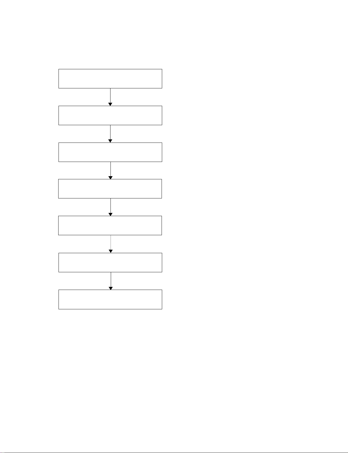
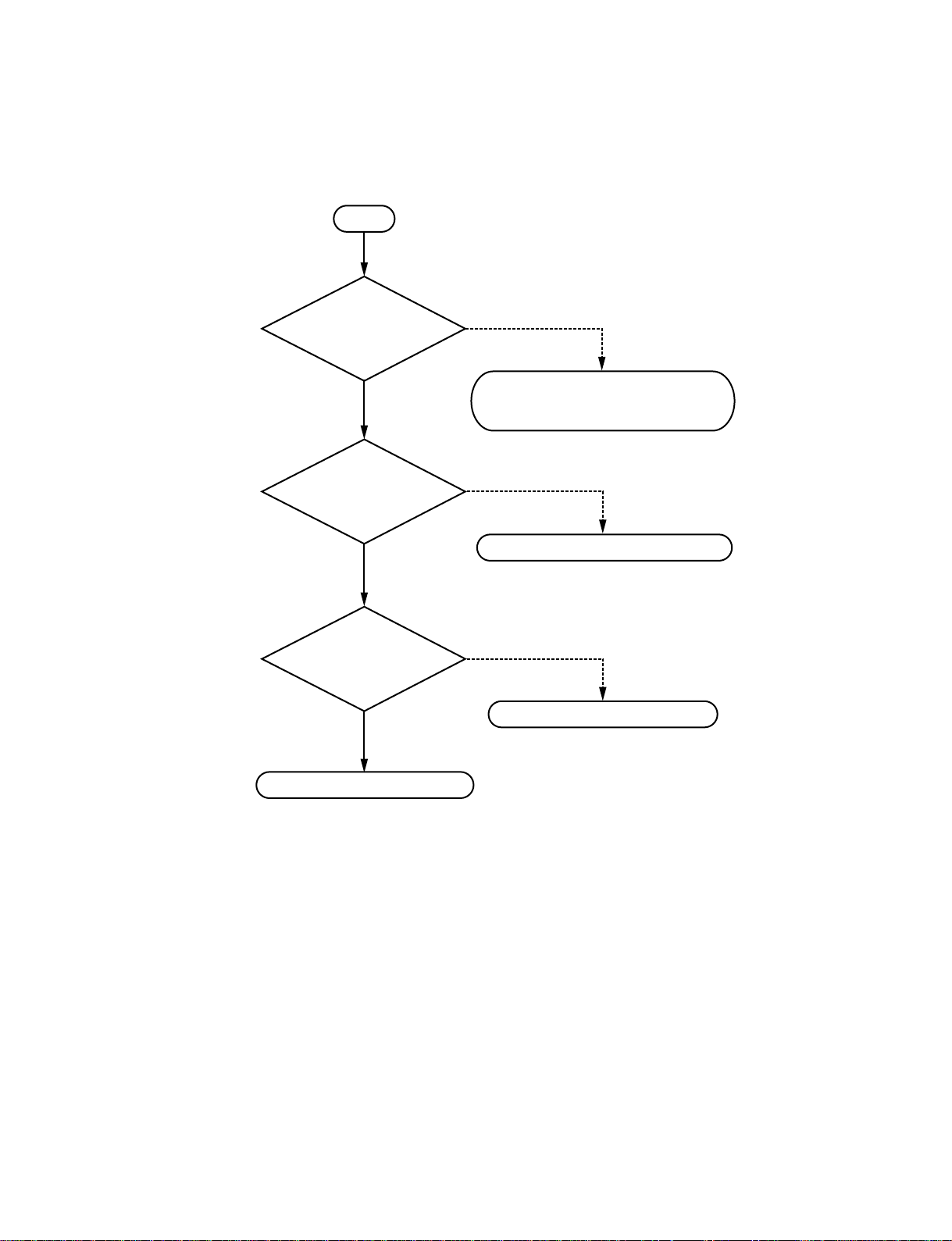
1-2. Flowchart of Installation
Place used
Unpacking
Check of supplied accessories
Power and cable connection, and
preparation
Start the power of the system and
initialize.
<Refer to “1-1. Caution on Installation” on page 1-1.>
<Refer to “1-3. System Connections” on page 1-8.>
<Refer to “1-4. Initialization” on page 1-10.>
Initialize the related block.
End
<“1-5. System Setting” on page 1-17.>
PCS-1/PCS-1P
1-7
Page 12

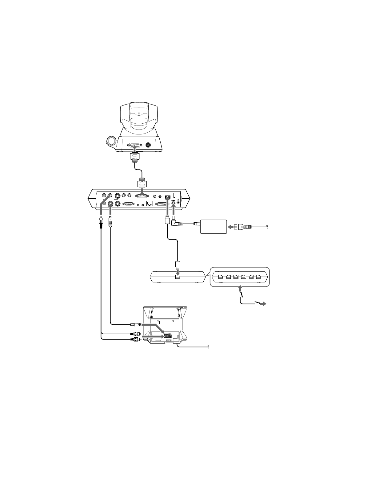
1-3. System Connections
This section describes the typical system connections.
m
. Be sure to turn off all the equipment before making any connections.
. Do not connect/disconnect the camera cable with the power on. Doing so may damage the Camera Unit
or Communication Terminal.
. For safety, do not connect the 100BASE-TX/10BASE-T connector to a network that applies an excess
voltage via the 100BASE-TX/10BASE-T connector
1-3-1. When Used in LAN (100BASE-TX/10BASE-T)
PCS-C1 Camera Unit
TERMINAL VISCA OUT
to TERMINAL
PCS-P1
Communication
Terminal
to AUDIO
OUT
Audio
connecting
cable
*
supplied
**
not supplied
AUDIO OUT
(MIXED)
AUX
*
AUDIO IN
AUX1–
VIDEO IN
–AUX2
VIDEO OUT
MAIN–MONITOR–SUB
RGB OUT DSB
to VIDEO
OUT
MONITOR
MAIN
S-video
connecting
*
cable
to S-video
to audio input
input
CAMERA UNIT MIC
IR OUT
12
Camera cable
*
to CAMERA UNIT
(PLUG IN POWER)
ISDN UNIT
100BASE-TX
10BASE-T
12
DC 19.5V
WHITE
BOARD
to DC19.5V
to 100BASE-TX/
10BADSE-T
UTP cable (category 5, straight)
TV monitor
**
PCS-AC195
AC adaptor
to a wall outlet
Power cord
to wall outlet
**
*
to LAN
1-8
PCS-1/PCS-1P
Page 13
1-3-2. When Used in ISDN
n
Do not connect/disconnect the camera cable or the interface cable with the power on. Doing so may
damage the Camera Unit, Communication Terminal or ISDN Unit.
PCS-C1 Camera Unit
TERMINAL VISCA OUT
to TERMINAL
PCS-P1
Communication
Terminal
to AUDIO
OUT
Audio
connecting
cable
*
supplied
**
not supplied
(MIXED)
AUX
AUDIO OUT
VIDEO OUT
AUX1–
VIDEO IN
–AUX2
MAIN–MONITOR–SUB
RGB OUT DSB
AUDIO IN
CAMERA UNIT MIC
IR OUT
12
to VIDEO
OUT
MONITOR
MAIN
(supplied with the PCS-B768)
S-video
connecting
*
cable
*
to S-video
input
to audio input
Camera cable
*
to CAMERA UNIT
(PLUG IN POWER)
ISDN UNIT WHITE
12
100BASE-TX
10BASE-T
DC 19.5V
to ISDN
UNIT
Interface cable
PCS-B768 ISDN Unit
TV monitor
BOARD
to DC19.5V
to
TERMINAL
**
PCS-AC195
AC adaptor
Front
**
to ISDN 1-6
ISDN modular
to a wall outlet
Power cord
to a wall outlet
123 45 6
to ISDN
**
cable
*
PCS-1/PCS-1P
1-9
Page 14

1-4. Initialization
1-4-1. Inserting Batteries into the Remote
Commander
Most of the operations with the Video Communication
System can be controlled with the supplied Remote
Commander.
1. Remove the battery compartment cover.
2. Insert two size AA (R6) batteries (supplied) with
correct polarities into the battery compartment.
n
Be sure to insert the batteries _ side first. Inserting them
forcibly + side first may damage the insulated film
covering the batteries and cause a short circuit.
3. Replace the cover.
m
Battery life
When the Remote Commander does not function properly,
replace both the batteries with new ones.
Notes on batteries
. To avoid damage from possible battery leakage or
corrosion, observe the following:
. Make sure to insert the batteries with the polarities in the
correct direction.
. Do not mix old and new batteries, or different types of
batteries.
. Do not attempt to charge the batteries.
. If you do not intend to use the Remote Commander for a
long period of time, remove the batteries.
. If battery leakage occurs, clean the battery compartment
and replace all the batteries with new ones.
1-10
PCS-1/PCS-1P
Page 15

1-4-2. Turning On/Off the TV Monitor Together With the Communication
Terminal
If you use a Sony TV, insert the IR repeater under the remote sensor of the TV. Once you set the IR
repeater, the TV will turn on or go to standby together with the Communication Terminal when you press
the I/O button on the supplied Remote Commander.
TV monitor
CAMERA UNIT MIC
IR OUT
12
100BASE-TX
10BASE-T
(PLUG IN POWER)
12
ISDN UNIT
WHITE
BOARD
DC 19.5V
DSB
Remoted sensor
IR repeater (supplied)
to IR OUT
n
If the TV monitor is not turned on by pressing the I/O button on the Remote Commander, change the “IR
Repeater Mode” setting in the General Setup menu.
For details on the “IR Repeater Mode” setting, see “General Setup Menu” on page 1-18.
PCS-1/PCS-1P
1-11
Page 16

1-4-3. Adjust the Volume of a Monitor
Television
1-4-4. Installing the Communication
Terminal and Camera
Adjust the television side after the volume is adjusted on
the PCS-1/1P side.
1. Press the volume/bright button of a remote controller
and adjust so that the volume adjustment bar is in the
center position
2. Adjust the volume of a monitor television.
Set to the volume in which the remote voice can be
heard well.
After adjustment is completed, adjust the volume on
the PCS-1/1P side.
You can fix the Communication Terminal or the Camera to
your chosen place of installation using the supplied Velcro.
1. Stick the supplied Velcro to the bottom of the
Communication Terminal or Camera.
3
3
Bottom of the Communication
Terminal
3
3
Bottom of the Camera Unit
2. Stick another piece of Velcro to the installation place.
3. Install the Communication Terminal or the Camera on
the installation place by securing the two pieces of
Velcro.
1-12
PCS-1/PCS-1P
Page 17

1-4-5. Turning On
1. Turn on the TV monitor.
If the IR repeater is installed in the TV monitor, set the
TV monitor to standby mode. The TV monitor will
turn on simultaneously when the Communication
Terminal is turned on.
2. Turn on the power of any other equipment to be used
for the videoconference.
3. Set the power switch on the right side of the
Communication Terminal to the on position (I).
POWER indicators
(Light in green.)
The Communication Terminal turns on after a while. Three
indicators on the front of the Communication Terminal and
the POWER indicator on the camera light, then only the
POWER indicators on both units remain on in green. The
launcher menu will appear on the monitor screen and the
picture shot by the local camera will also appear in the
launcher menu.
Launcher menu
Connect
Phone Book
Dial
Menu
Show Help
IP:0.0.0.0
Video:Main
Power switch
Angle Adj.
ISDN:012345678912
Audio:MIC(INT)+AUX
m
. After the power is turned on, the camera moves
automatically for trial operation. Be careful not to catch
your finger.
. If you use force to prevent the camera moving, it may
not resume moving and not output a signal to the
Communication Terminal. In this case, turn off the
Terminal, and turn it on again.
. When you turn on the power of the Communication
Terminal for the first time after installation, the setup
wizard will appear after the self-diagnosis is completed.
Set up your system following the wizard.
. For setups using the wizard, see “Setting Up the System
for the First Time - Initial Setup Wizard” on page 1-14.
Standby Mode Function
To save power the Communication Terminal will enter
standby mode if you do not operate it for a specified period
of time.
When the Communication Terminal is in standby mode,
the POWER indicator lights in orange. Once the
Communication Terminal receives a call, the standby
mode is automatically released.
To release the standby mode
Press the I/O button on the Remote Commander.
To specify the standby time
Specify the time that you want the system to remain on
before entering into standby mode (1 to 99 minutes) using
“Standby Time” in the General Setup menu. If you do not
want the system to enter the standby mode, set “Standby
Mode” in the General Setup menu to “Off”.
For the “Standby Time” and “Standby Mode” settings, see
“General Setup Menu” on page 1-17.
m
. The POWER indicator on the camera goes off when the
system enters standby mode.
. If you use a Sony TV monitor with the IR repeater
installed under the remote sensor, the TV monitor will
enter standby mode together with the Communication
Terminal.
PCS-1/PCS-1P
1-13
Page 18

1-4-6. When the Power was First Turned on
after Installation
When you turn on the Communication Terminal for the
first time after installation and the self-diagnosis is
completed, the setup wizard appears on the monitor screen.
Register your local system data with the setup wizard using
the Remote Commander.
n
You can change the settings made with the setup wizard
later using the Setup menus.
1. Select the language used for the on-screen menus and
messages in the Language Setup Wizard.
Language: Select one of seven languages; English,
French, German, Japanese, Spanish, Italian, Chinese.
Language Setup Wizard
Language
English
3. Set the following items on the ISDN line.
ISDN Setup Wizard
Country/Region
Country/Region Code
Protocol
USA
1
National ISDN
CancelNextPrevious
Country/Region:
Select your country or region.
Country/Region Code:
Enter your country code or region code with the
number buttons on the Remote Commander.
Protocol:
Select the protocol of the ISDN line you are using.
4. Use the ↑, ↓, ← or → button to select “Next”, then
press the PUSH ENTER button.
CancelNext
2. Use the ↑, ↓, ← or → button on the Remote
Commander to select “Next”, then press the PUSH
ENTER button.
The ISDN Setup Wizard appears.
n
When you are not using the ISDN line, select “Next”
to display the LAN Setup Wizard, then proceed to step
9.
1-14
PCS-1/PCS-1P
Page 19

5. Enter the telephone number of the ISDN used by the
system.
When you use one ISDN line, enter the same number
both in the A1 and A2 text boxes (except for the USA
and Canada).
7. Enter the sub-addresses.
Only numerals are available for a sub-address.
When you use one ISDN line, enter the same number
both in the A1 and A2 text boxes (except for the USA
and Canada).
Area Code Local Number
A1
A2
B1
B2
C1
C2
CancelNextPrevious
Area Code:
Enter the area code. Do not enter the first “0” number.
Local Number:
Enter the telephone number.
When you select Auto SPID (only for customers in
the USA and Canada)
You can automatically set up the Area Code and Local
Number on this page, and SPID items in the SPID
menu.
n
When 2-6 ISDN lines are used, enter the telephone
numbers in the B1 to F2 text boxes in addition to the
A1 and A2 boxes. To open the menu with D1 to F2
text boxes, select “Next”, then press the PUSH
ENTER button.
6. Use the ↑, ↓, ← or → button to select “Next”, then
press the PUSH ENTER button.
Sub Address
A1
A2
B1
B2
C1
C2
CancelNextPrevious
n
When 2-6 ISDN lines are used, enter the sub-addresses
in the B1 to F2 text boxes in addition to the A1 and A2
boxes. To open the menu with these text boxes, select
“Next”, then press the PUSH ENTER button.
8. Use the ↑, ↓, ← or → button to select “Next”, then
press the PUSH ENTER button.
For customers in other countries than the USA and
Canada
The LAN Setup Wizard appears.
For customers in the USA and Canada
The ISDN Setup Wizard (SPID menu) appears.
Set the SPID items, then select “Next” and press the
PUSH ENTER button.
The LAN Setup Wizard appears.
For details on the SPID settings, see “SPID Setting for
Customers in the USA and Canada” on page 46.
n
When you do not use the LAN, select “Next” to
display the message window for confirmation, then
proceed to step 11.
PCS-1/PCS-1P
1-15
Page 20

9. Set the following items on the LAN.
LAN Setup Wizard
11. Use the ↑, ↓, ← or → button to select “Save”, then
press the PUSH ENTER button.
The settings are saved.
DHCP Mode
Host Name
IP Address
Network Mask
Gateway Address
DNS Address
Auto
. . .
. . .
. . .
. . .
CancelNextPrevious
DHCP Mode:
Sets the DHCP (Dynamic Host Configuration Protocol).
Auto:
Automatically assigns your IP address, network mask,
gateway address and DNS address.
Off:
Deactivates DHCP. In this case set your IP address,
network mask, gateway address and DNS address
manually.
Host Name:
Enter your host name.
IP Address:
Enter your IP address.
Network Mask:
Enter your network mask.
Gateway Address:
Enter your default gateway address.
DNS Address:
Enter your DNS (Domain Name System) server
address.
n
When you set “DHCP Mode” to “Auto”, the assigned
IP address is shown in the launcher menu or Machine
Information menu.
When you do not know how to set up the LAN
configuration, contact your network administrator.
10. Use the ↑, ↓, ← or → button to select “Next”, then
press the PUSH ENTER button.
The message window for confirmation appears.
Save
CancelPrevious
To cancel the setting
Press the ↑, ↓, ← or → button to select “Cancel”, then
press the PUSH ENTER button.
To go back to the previous wizard
Press the ↑, ↓, ← or → button to select “Previous”, then
press the PUSH ENTER button.
1-16
PCS-1/PCS-1P
Page 21

1-5. System Setting
The contents of a setting menu are shown in the table below.
Change the setting as required.
Outgoing setting
Multipoint
A multipoint setting
menu can be set
only when optional
H.320 MCU
software or H.323
MCU software is
installed.
General setting
PCS-1/PCS-1P
Item
Line type
Bonding
Number of lines used
LAN band used
Prefix selection
Restricted network
Video system
Number of video frames
Audio system
Remote camera control
T.120 data
Prefix -A/-B/-C
Voice telephone
Detail setting
Name entry
Multipoint mode
Broadcasting mode
Number of lines used
LAN band used
Restricted network
Video system
Audio system
Terminal name display
Remote camera control
Terminal name
Dual monitor
Monitor output
(Sub-monitor output)
Standby mode
Standby time
Passage time display
Use of DSB
List registration after
conference termination
T.120 PC address
Select the line interface (LAN, ISDN, or voice telephone) used.
Contents of setting
Select “On” when connecting using a bonding interface through which the
remaining lines can also be connected by only dialing one line when multiple
ISDN lines are used. Select “Auto” when automatically adjusting to the remote
side.
Select the number of ISDN lines used during outgoing of bonding.
!B, 2B, 3B, 4B, 5B, 6B, 8B, or 12B channel can be selected.
Set the bandwidth (1 to 1920) when communicating via LAN.
Set the prefix number used when connecting using an ISDN line.
Select the communication rate (Auto or 56K) when connecting using an ISDN
line.
In a few countries (America, etc.) and regions, two types of rates (64 Kbps and 56
Kbps) are used.
Usually, select “Auto” as the communication rate of ISDN.
Select a video coding system.
Select the maximum number of video transmission frames (15 fps or 30 fps).
Select an audio coding system.
Set to “On” when controlling the camera on the remote side. Set to “Off” when
not controlling it.
Set to “On” when making the data conference conforming to T.120 using
NetMeeting. Set to “Off” when not making it.
Set the prefix (outgoing number).
Select the voice compression system during voice meeting.
Set to “On” when you want to have outgoing attributes for each dial list. Set to
“Off” when you do not want.
Set to “On” when recording the user name in a communication log before
communication. Set to “Off” when not recording it.
Set to “On” when making a conference using an internal MCU (multipoint
conference) function. Set to “Off” when not making it.
Set to “Divide” when displaying the connected terminal in the broadcasting
display mode of a multipoint conference by division. Set to “Audio detect” when
displaying the terminal with the highest volume in the participated terminals.
Select the number of ISDN lines for each sub-terminal of a multipoint conference.
Enter the bandwidth when a multipoint conference is made using LAN. The
bandwidth can be set in the range of 1 kHz to 1920 kHz.
Select the communication rate (Auto or 56 K) when connecting using an ISDN
line. In a few countries (America, etc.) and regions, two types of rates (64 Kbps
and 56 Kbps) are used.
Usually, select “Auto” as the communication rate of ISDN.
Select a video coding system.
Select an audio coding system.
Set to “On” when displaying the terminal name at a connection point on the
monitor screen during disconnection. Set to “Off” when not displaying it.
Set to “On” when controlling the camera on the remote side. Set to “Off” when
not controlling it.
Enter the terminal name to be notified in external MCU.
Set to “On” when using a dual monitor function with the two monitors connected.
Select whether a signal should be output to the monitor connected to which output
terminal. When “Dual monitor” is set to “On”, the menu is changed to “Sub-
monitor output”. Select whether a signal should be output to the sub-monitor
connected to which output terminal.
Set to “On” when using the standby mode. Set to “Off” when not using it.
Set the time (1 to 99 minutes) required until the unit is put into the standby mode
when the standby mode is “On”.
Set to “On” when displaying the talking time. Set to “Off” when not displaying it.
Set to “On” when using optional data solution box PCS-DSB1. Set to “Off” when
not using it.
Set to “On” when registering the remote user in an address book after a conference
is terminated. Set to “Off” when not registering it.
Enter the IP address of the computer used when the data conference conforming to
T.120 is made using NetMeeting.
Initial value
LAN
Auto
12B
1024
None
Auto
All capabilities
15 fps
All capabilities
On
Off
Blank
Auto
Off
Off
Off
Divide
2Bx5
1024
Auto
All capabilities
All capabilities
On
On
Blank
Off
Video terminal of
main unit
Off
On
On
On
Blank
1-17
Page 22

General setting
ISDN setting
Incoming setting
Audio setting
Setting for
administrator
Setting of LAN
Item
Language setting/
Language
IR repeater mode
Camera control
reception
Memory Stick format
Country/region
Country/region number
Protocol
Trunk exchange
number/local number
Sub-address
Automatic incoming
Number of lines used
Restricted network
LAN band used
ISDN dial-in
Video system
Number of video frames
Audio system
Remote camera control
T.120 data
Input switching
Microphone selection
Lip sync
Echo canceller
Beep Sound
Recording mute
Administrator password
Super-user password
Remote access
password
Web monitor
Storage of address book
Loading of address book
DHCP mode
Host name
IP address
Network mask
Gateway address
DNS address
Gate keeper used
Gate keeper address
User name
Select the language (English, French, German, Japanese, Spanish, Italian, or
Contents of setting
Chinese) of the menu and message displayed on the screen.
Select the mode for putting the monitor into the standby state or turning on the
power when a Sony’s monitor is used. Usually, set to “Mode 1”.
Set to “on” when receiving the camera control command from the remote side.
Set to “Off” when not receiving it.
Execute the format of a Memory Stick.
Select the country and region in which a communication terminal is used. Set to
“Japan” when a communication terminal is used in Japan.
Set the country/region number. Set to “81” when a communication terminal is
used in Japan.
Select the protocol of the ISDN line used. Select “NTT” when an ISDN line is
used in Japan.
Set the connected ISDN line number. Be sure to set the ISDN number when a
bonding interface is used.
Enter it when a sub-address is registered
Select automatic incoming “On” and manual incoming “Off”.
Select the number of ISDN lines used during incoming.
!B, 2B, 3B, 4B, 5B, 6B, 8B, or 12B channel can be selected.
Select the communication rate (Auto or 56 K) when connecting using an ISDN
line.
In a few countries (America, etc.) and regions, two types of rates (64 Kbps and 56
Kbps) are used.
Usually, select “Auto” as the communication rate of ISDN.
Set the bandwidth (1 to 1920) when communicating via LAN.
Set to “On” when using multiple subscriber numbers during connection using an
ISDN line. Set to “Off” when not using them.
Select a video coding system.
Select the maximum number of video transmission frames (15 fps or 30 fps).
Select an audio coding system.
Set to “On” when controlling the camera on the remote side. Set to “Off” when
not controlling it.
Set to “On” when making the data conference conforming to T.120 using
NetMeeting. Set to “Off” when not making it.
Select the audio input (MIC, AUX, or MIC + AUX).
Select the microphone used (internal, external, DSB MIC, or DSB AUX IN).
Set to “On” when using a lip sync function. Set to “Off” when not using it.
Set to “Internal” when using an internal echo canceller and set to “External” when
using an external echo canceller. Set to “Off” when not using an internal echo
canceller.
Set to “On” when generating a beep sound during reception of a remote controller
signal. Set to “Off” when not generating it.
Set to “On” when outputting a voice to the AUDIO OUT (MIXED) terminal. Set
to “Off” when not outputting it.
Set the password for an administrator. The administrator can operate a setting
menu and address book menu.
Set the password for a super-user. The super-user can operate an address book
menu.
Set the password when accessing from Web.
Select whether to permit the conference state monitoring function (the updating of
JPEG screen) from Web.
Save the data in an address book menu in “Memory Stick”.
Load the data in an address book menu from “Memory Stick”.
Set whether to use DHCP (Dynamic Host Configuration Protocol). Set to “Auto”
when automatically acquiring an IP address, net mask, gateway address, and DNS
address. Set to “Off” when not automatically acquiring it.
Set the host name of this unit.
Set the IP address of this unit.
Set the network mask of this unit.
Set a default gateway address.
Set a DNS (Domain Name System) server address.
Set to “On” when using a gate keeper and set to “Off” when not using it. Set to
“Auto” when automatically searching a gate keeper.
Set the IP address of a gate keeper.
Set the user name (H.323 alias) registered in a gate keeper.
Initial value
Japan/Japanese
MODE1
On
Japan
81
NTT
On
12B
Auto
1024 Kbps
Off
All capabilities
15 fps
All capabilities
On
Off
MIC
Internal
Off
Internal
On
On
On
Off
Blank
Blank
Blank
Blank
Blank
Off
Blank
Blank
1-18
PCS-1/PCS-1P
Page 23

Setting of LAN
Item
User number
SNMP service
Set the user number (E.164 number) registered in a gate keeper.
Contents of setting
Set to “On” when enabling the service of an SNMP (Simple Network Management
Initial value
Blank
Off
Protocol) agent. Set to “Off” when disabling it.
Trap transmission
Set the IP address of an SNMP manager that transmits a trap.
Blank
destination
Community name
Set the community name that an SNMP manager manages. Usually, set to
Public
“Public”.
Description of device
Installation place
Contact of administrator
NAT setting
This is the description of this device. It has been input as “Videoconference
Device”. Cannot be changed.
Set the place in which this unit is installed.
Set the information on the administrator of this unit.
Set to “On” when connecting this unit to the local network in which NAT
Videoconference
Device
Blank
Blank
Off
(Network Address Translation) was used. Set to “Off” when not connecting it.
NAT address
Packet retransmission
Set the IP address on the global side that NAT uses.
Used for future function expansion.
Blank
Blank
request
Optimum rate control
Set to “On” when always optimizing the LAN band used. Set to “Off” when not
Off
optimizing it.
Port number used
Select whether to fix the TCP port number and UDP port number.
Default value
User setting: The port number that the user sets is used.
Default value: The default port number is used. TCP port number 2253 and UDP
port number 49152 are set.
Communication
state
TCP port number
UDP port number
Remote camera control
T.120 data
Line I/F
Line rate
Set the TCP port number when “Port number used” is “User setting”.
Set the UDP port number when “Port number used” is “User setting”.
Display whether a camera remote control can be performed.
Display whether a T.120 data conference can be performed.
Display the line interface used.
Display the number of connected lines and the transmission rate during
Blank
Blank
communication.
DSB
White board
Audio coding system
Video coding system
Video frame rate
LSD rate
MLP rate
HMLP rate
Information
Host version
ISDN UNIT version
DSB version
DSP version
Software option
Option I/F
Host name
IP address
MAC address
Serial number
(*1) : Displayed with the transmission and reception columns divided. The setting state of this side is displayed on the transmission column, and the reception
enable state of this side is displayed on the reception column.
Display whether data solution box PCS-DSB1 can be used.
Used for future function expansion.
Display the current audio coding system.
Display the current video coding system.
Display the maximum frame rate of a motion picture.
Display the data transmission rate of LSD.
Display the data transmission rate of MLP.
Display the data transmission rate of HMLP.
The software version of a communication terminal is displayed.
The version of connected ISDN unit PCS-B768 is displayed.
The version of connected data solution box PCS-DSB1 is displayed.
The version of a video and audio codec is displayed.
The type of installed optional MCU software is displayed.
The connected optional equipment is displayed.
The host name is displayed.
The IP address is displayed.
The MAC address is displayed.
The serial number is displayed.
(*1)
PCS-1/PCS-1P
1-19
Page 24

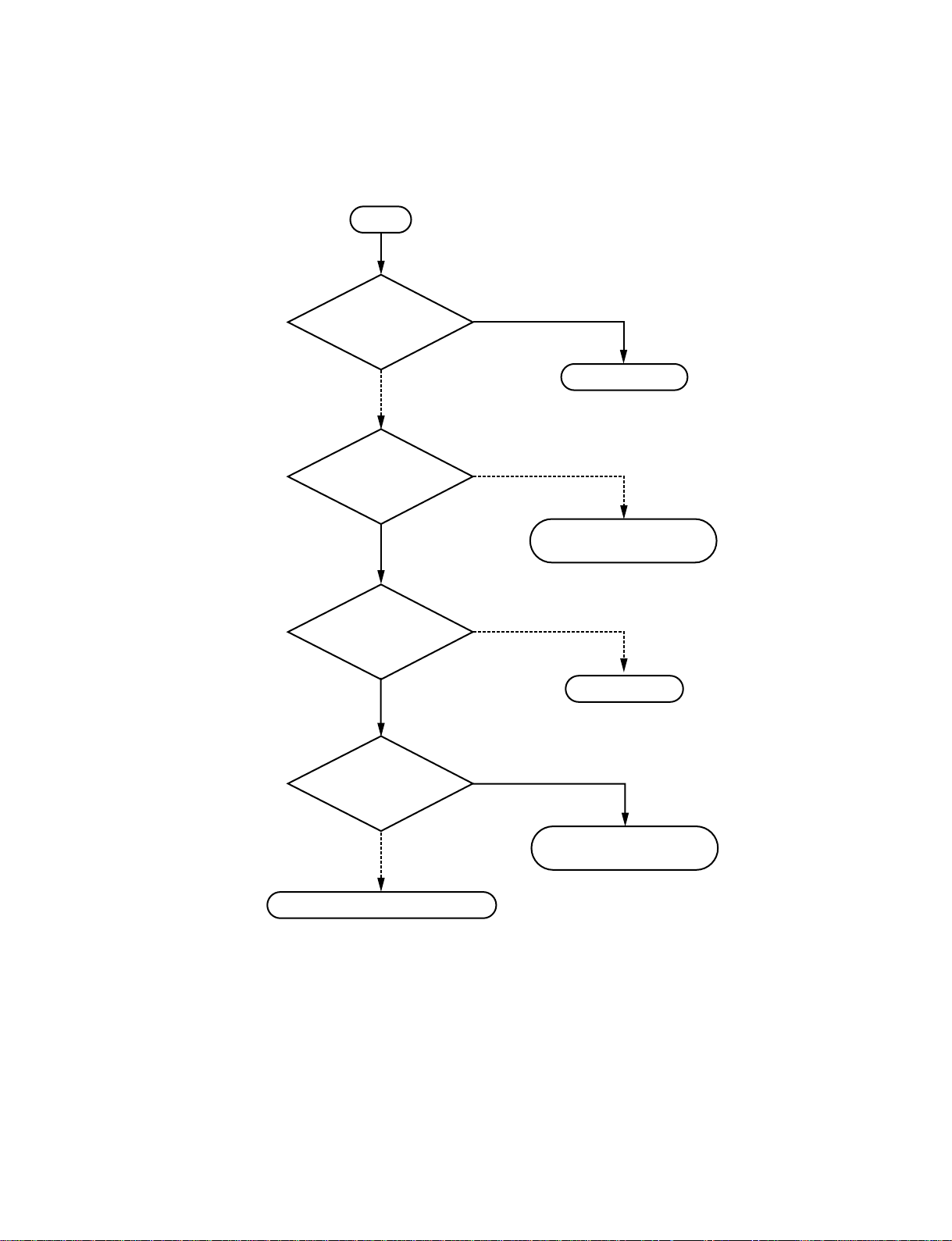
1-6. Flowchart of Opening Test
Opening test
NO
NO
Communicate
using ISDN?
YES
ISDN outgoing
ISDN incoming
Communicate
using LAN?
<Refer to “1-6-1. Outgoing Procedure of ISDN” on page 1-21.>
<Refer to “1-6-2. Incoming Procedure of ISDN” on page 1-23.>
1-20
YES
LAN outgoing
LAN incoming
Opening test completion
<Refer to “1-6-3. Outgoing Procedure of LAN” on page 1-24.>
<Refer to “1-6-4. Incoming Procedure of LAN” on page 1-26.>
PCS-1/PCS-1P
Page 25

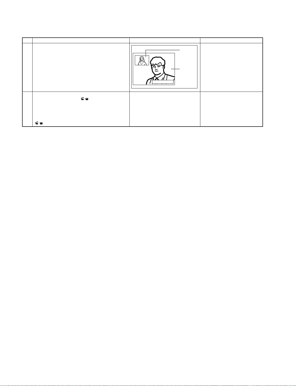
1-6-1. Outgoing Procedure of ISDN
n
It is required that the line number used in the other end is entered in the area code and local number of the ISDN setting
menu of the other end.
Item
1.
Select “Dial” from the launcher menu using ↑, ↓, ←, and →
buttons of a remote controller and press the decide button,
or press the connect/disconnect ( / ) button of a remote
controller.
2.
Select “Line type” using ↑, ↓, ←, and → buttons of a
remote controller and press the decide button, or select
“ISDN” from the set item using ↑ or ↓ button and press the
decide button.
Operation
Connect
Show Help
Phone Book
Dial
Menu
Dial
IP
A2
B1
B2
Screen Remarks (Confirmation item)
The dial menu is displayed.
Angle Adj.
IP:0.0.0.0
Video:Main
ISDN:012345678912
Audio:MIC(INT)+AUX
Line I/F
LAN
ISDN
LAN Bandwidth:
ISDN(Telephone)
1024 Kbps
3.
Select line input column A using ↑, ↓, ←, and → buttons of
a remote controller and press the decide button. Then, enter
the remote line number.
4.
Select “Number of lines used” using ↑, ↓, ←, and →
buttons of a remote controller and press the decide button.
Select the number of connected lines from the set item using
↑ or ↓ button and press the decide button.
5.
Select “Dial” at the bottom of a menu using ↑, ↓, ←, and →
buttons of a remote controller and press the decide button,
or press the connect/disconnect ( / ) of a remote
controller.
More Options
Dial
A
More Options
Dial
IP
A2
B1
B2
More Options
Dial
A
Dial Save
Line I/F
ISDN
Number of Lines
12 B
Dial Save
Line I/F
LAN
LAN Bandwidth:
1024 Kbps
1B
2B
3B
4B
5B
6B
8B
12B
Dial Save
Line I/F
ISDN
Number of Lines
6 B
“Outgoing (ISDN)” is displayed on
the screen, and the ON LINE lamp
(blue) blinks.
PCS-1/PCS-1P
More Options
Dial Save
1-21
Page 26
Item
6.
The remote side makes a response.
7.
Disconnection
Operation
Press the connect/disconnect ( / ) button of a remote
controller. A confirmation message on whether to
disconnect a line is then displayed.
Select “OK” using a ← or → button of a remote controller
and press the decide button, or press the connect/disconnect
( / ) button of a remote controller again.
Screen Remarks (Confirmation item)
The ON LINE lamp (blue) lights.
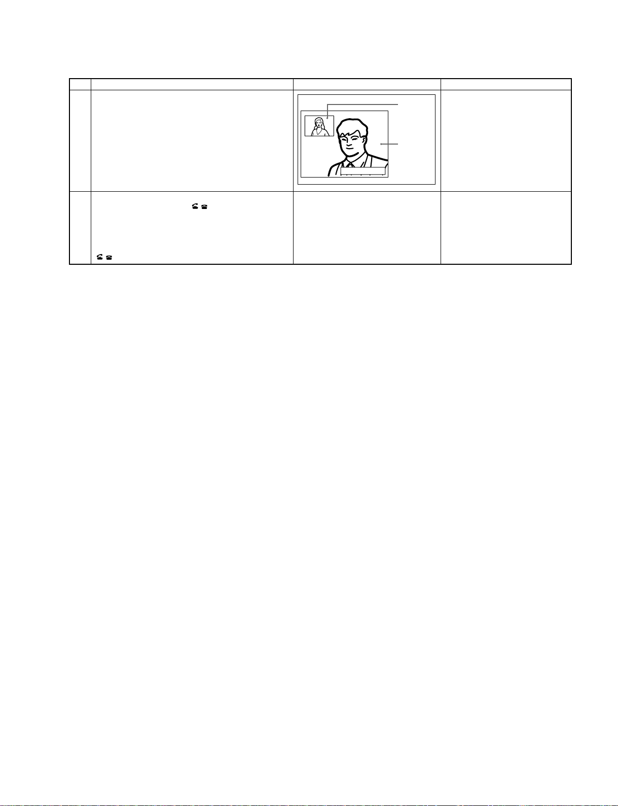
Picture on
the local site
“Start meeting” is displayed, and the
remote voice and image are heard and
displayed from the monitor television.
Picture on
the remote
site
Meeting starts!
The line is disconnected and the
conference is terminated. The current
display returns to a launcher menu.
1-22
PCS-1/PCS-1P
Page 27

1-6-2. Incoming Procedure of ISDN
Meeting starts!
Picture on
the local site
Picture on
the remote
site
Meeting starts!
Picture on
the local site
Picture on
the remote
site
n
It is required that the line number used in this unit is entered in the area code and local number of the ISDN setting menu
before receiving a signal from the other end.
Item
1.
Incoming from the remote side
2.
<For automatic response>
Operation
Incoming Call (ISDN)
0987654321
XX.XX.XX.XX
Screen Remarks (Confirmation item)
An incoming sound occurs.
LAN
Cancel
Meeting starts!
Picture on
the local site
Picture on
the remote
site
“Incoming” is displayed on the
screen.
During connection, “Start meeting” is
displayed, and the remote voice and
image are heard and displayed from
the monitor television.
<For manual response>
3.
Remote disconnection
Connect
Show Help
Connect
Show Help
Receive a signal. Respond to?
Phone Book
XX.XX.XX.XX
Dial
Menu
IP:0.0.0.0
Video:Main
Phone Book
Dial
Menu
IP:0.0.0.0
Video:Main
ISDN
CancelO K
ISDN:012345678912
Audio:MIC(INT)+AUX
ISDN:012345678912
Audio:MIC(INT)+AUX
A call sound occurs and the guide
screen for incoming appears on the
screen.
Select “OK” using a ← or → button
of a remote controller and press the
decide button.
Angle Adj.
During connection, “Start meeting” is
displayed, and the remote voice and
image are heard and displayed from
the monitor television.
The message of conference
termination is displayed on the screen
and the current display returns to a
launcher menu.
Angle Adj.
PCS-1/PCS-1P
1-23
Page 28
1-6-3. Outgoing Procedure of LAN
Item
1.
Select “Dial” from the launcher menu using ↑, ↓, ←, and →
Operation
buttons of a remote controller and press the decide button,
or press the connect/disconnect ( / ) button of a remote
controller.
2.
Select “Line type” using ↑, ↓, ←, and → buttons of a
remote controller and press the decide button, or select
“LAN from the set item using a ↑ or ↓ button and press the
decide button.
3.
Select an IP address input column using ↑, ↓, ←, and →
buttons of a remote controller and press the decide button.
Then, enter the remote IP address.
m
. Enter the host name and domain name (example:
host.domain) in an IP address input column when a DNS
server is used. Enter the user name or user number,
registered in the remote LAN set menu, in an IP address
input column when a gate keeper is used.
. To enter the delimitation of an IP address, press the →
button or # button.
4.
Select “LAN band used” using ↑, ↓, ←, and → buttons of a
remote controller and press the decide button. Select the
band used from the set item using a ↑ or ↓ button and press
the decide button.
5.
Select “Dial” at the bottom of a menu using ↑, ↓, ←, and →
buttons of a remote controller and press the decide button,
or press the connect/disconnect ( / ) of a remote
controller.
Connect
Show Help
Phone Book
Dial
Menu
Dial
IP
A2
B1
B2
More Options
Dial
IP
A2
B1
B2
C1
C2
More Options
Dial
IP
A2
B1
B2
C1
C2
Screen Remarks (Confirmation item)
The dial menu is displayed.
Angle Adj.
IP:0.0.0.0
Video:Main
ISDN:012345678912
Audio:MIC(INT)+AUX
Line I/F
LAN
LAN
ISDN
LAN Bandwidth:
ISDN(Telephone)
1024 Kbps
Dial Save
Line I/F
LAN
LAN Bandwidth
1024 Kbps
Dial Save
During connection, “Start meeting” is
displayed, and the remote voice and
image are heard and displayed from
the monitor television.
“Outgoing (LAN)” is displayed on the
screen.
Line I/F
LAN
LAN Bandwidth
1024 Kbps
1-24
More Options
Dial Save
PCS-1/PCS-1P
Page 29
Item
Meeting starts!
Picture on
the local site
Picture on
the remote
site
6.
The remote side makes a response.
7.
Disconnection
Operation
Press the connect/disconnect ( / ) button of a remote
controller. A confirmation message on whether to
disconnect a line is then displayed.
Select “OK” using a ← or → button of a remote controller
and press the decide button, or press the connect/disconnect
( / ) button of a remote controller again.
Screen Remarks (Confirmation item)
The ON LINE lamp (blue) lights.
“Start meeting” is displayed, and the
remote voice and image are heard and
displayed from the monitor television.
The line is disconnected and the
conference is terminated. The current
display returns to a launcher menu.
PCS-1/PCS-1P
1-25
Page 30

1-6-4. Incoming Procedure of LAN
Item
1.
Incoming from the remote side
2.
<For automatic response>
<For manual response>
Operation
Incoming Call (ISDN)
0987654321
Connect
Phone Book
Dial
Menu
Show Help
Screen Remarks (Confirmation item)
An incoming sound occurs.
XX.XX.XX.XX
LAN
Cancel
Meeting starts!
Picture on
the local site
Picture on
the remote
site
“Incoming” is displayed on the
screen.
During connection, “Start meeting” is
Picture on
the local site
displayed, and the remote voice and
image are heard and displayed from
the monitor television.
Picture on
the remote
site
Meeting starts!
A call sound occurs and the guide
screen for incoming appears on the
screen.
Receive a signal. Respond to?
XX.XX.XX.XX
IP:0.0.0.0
Video:Main
LAN
CancelO K
ISDN:012345678912
Audio:MIC(INT)+AUX
Angle Adj.
Select “OK” using a ← or → button
of a remote controller and press the
decide button.
3.
Remote disconnection
Connect
Show Help
Phone Book
Dial
Menu
Meeting starts!
IP:0.0.0.0
Video:Main
Picture on
the local site
Picture on
the remote
site
Angle Adj.
ISDN:012345678912
Audio:MIC(INT)+AUX
During connection, “Start meeting” is
displayed, and the remote voice and
image are heard and displayed from
the monitor television.
The message of conference
termination is displayed on the screen
and the current display returns to a
launcher menu.
1-26
PCS-1/PCS-1P
Page 31

Section 2
Maintenance
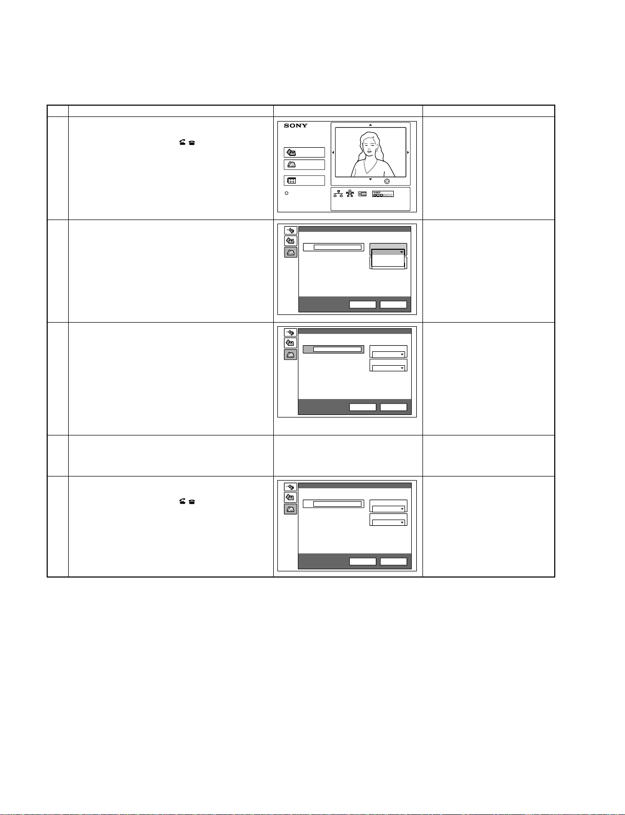
2-1. Confirmation Procedure of Local
Terminal Operation Using Self-Loop
A self-loop is the reflected loop in ISDN unit PCS-B768.
It does not operate when ISDN unit PCS-B768 is not
connected to the communication terminal.
Operation procedure
1. The launcher menu below is displayed when the power
switch of the communication terminal is turned on.
Connect
Phone Book
Dial
Menu
Show Help
2. Select a dial using ↑, ↓, ←, and → buttons of a remote
controller and press the decide button, or press the
connect/disconnect (I/O) button of a remote controller.
The dial menu is displayed.
Dial
Angle Adj.
4. Select the number of lines used.
Select “Number of lines used” using ↑, ↓, ←, and →
buttons of a remote controller and press the decide
button.
Then, select “12B” using ↑ and ↓ buttons and press
the decide button.
5. Select column A using ↑, ↓, ←, and → buttons of a
remote controller and press the decide button.
Enter * in column A from the remote controller two
times
Dial
A
More Options
Line I/F
ISDN
Number of Lines
6 B
Dial Save
6. Select “Dial” using ↑, ↓, ←, and → buttons of a
remote controller and press the decide button, or press
the connect/disconnect (I/O) button of a remote
controller.
A self-loopback is started and “Outgoing” is displayed
on the monitor screen. “Start meeting” is displayed
when the loopback is completed. In this case, confirm
that an image and voice are looped.
IP
A2
B1
B2
C1
C2
More Options
Line I/F
LAN
LAN Bandwidth
1024 Kbps
Dial Save
3. Select the line type.
Select “Line type” using ↑, ↓, ←, and → buttons of a
remote controller and press the decide button.
Then, select “ISDN” using ↑ and ↓ buttons and press
the decide button.
PCS-1/PCS-1P
2-1
Page 32

2-2. Separation of Components
The main troubles that occur during failure are described in the table below.
Trouble
1. The power is not turned on even if the power switch on the side panel is pressed. SS-01
2. The power is not turned on even if the power button of a remote controller is pressed. SS-02
3. The power is not turned on during automatic incoming. (ISDN) SS-03
4. The power is not turned on during automatic incoming. (LAN) SS-04
5. The power of a monitor television is not turned on during the power-on sequence. SS-05
6. The image from a camera is not displayed after the power is turned on. SS-06
7. No function can be operated using a remote controller. SS-07
8. The camera on the local side cannot be operated. SS-08
9. No line is connected. (ISDN) SS-09
10. No line is connected. (LAN) SS-10
11. No voice can be heard from the remote side after a line is connected. SS-11
12. No voice can be transmitted to the remote side after a line is connected. SS-12
13. No video input (object, AUX1, or AUX2) image can be displayed. The image of SS-13
a camera is displayed.
14. An image on the remote side is not displayed after a line is connected. SS-14
15. An image cannot be transmitted to the remote side after a line is connected. SS-15
2-2
PCS-1/PCS-1P
Page 33

1. The power is not turned on even if the power switch on the side panel is pressed.
SS-01
Is power
cord properly connected?
YES
Does POWER
(green) lamp light?
YES
Proceed to “5. The power of a monitor
television is not turned on during the
power-on sequence”.
NO
Connect it properly.
NO
Communication terminal
or AC adaptor is defective.
PCS-1/PCS-1P
2-3
Page 34

2. The power is not turned on even if the power button of a remote controller is pressed.
SS-02
Does POWER
(amber) lamp of main unit light?
YES
Is initial
screen displayed during
start when power is turned on again
using power switch on
side panel?
YES
Can light
emitting be checked
when local image is shot with
remote controller turned to camera and
when return button of
remote controller is
pressed?
YES
NO
Proceed to “1. The power is not
turned on even if the power switch on
the side panel is pressed”.
NO
Communication terminal is defective.
NO
Remote controller’s battery is
exhausted or remote controller is
defective.
2-4
Communication terminal is defective.
PCS-1/PCS-1P
Page 35

3. The power is not turned on during automatic incoming. (ISDN)
SS-03
Does POWER
(amber) lamp light?
YES
Is power
turned on when I/O
button of remote controller
is pressed?
YES
Are
communication terminal
and ISDN unit properly
connected?
YES
NO
Turn on power switch on side panel.
NO
Proceed to “2. The power is not
turned on even if the I/O button of a
remote controller is pressed”.
NO
Connect them properly.
Does STATUS
lamp of ISDN unit blink
in green?
YES
Is ISDN
modular cable properly
connected to IDSN
unit?
YES
Does STATUS
lamp of terminal, to which
ISDN modular cable of ISDN
unit is connected,
light in red?
YES
Communication terminal is defective.
NO
Communication terminal or
ISDN unit is defective.
NO
Connect it properly.
NO
ISDN unit or ISDN
line is defective.
PCS-1/PCS-1P
2-5
Page 36

4. The power is not turned on during automatic incoming. (LAN)
SS-04
Does POWER
(amber) lamp
light?
YES
Is power
turned on when I/O
button of remote controller
is pressed?
YES
Is LAN
cable properly
connected to 100BASE-
TX/10BASE-T
terminal?
YES
NO
Turn on power switch
on side panel.
NO
Proceed to “2. The power is not turned
on even if the I/O button of a remote
controller is pressed”.
NO
Connect it properly.
2-6
Is other
companies’ MCU or
GW used?
YES
Verify whole system including
network administrator.
NO
Communication terminal is defective.
PCS-1/PCS-1P
Page 37

5. The power of a monitor television is not turned on during the power-on sequence.
SS-05
Is the main power
switch of monitor TV
turned on?
YES
Is the monitor
TV compatible with this unit
(made by Sony)?
YES
Are the connection
and location of IR
repeater correct?
YES
Does the
setting of “IR repeater
mode” on page 3 of the
general setting menu
correspond to the
monitor?
YES
NO
Turn on the main power
switch of monitor TV.
NO
Turn on the power using the power switch of
monitor TV because it cannot be automatically
turned on.
NO
Connect and locate the IR repeater correctly.
NO
Set it properlycorrectly.
PCS-1/PCS-1P
IR repeater or communication
terminal is defective.
2-7
Page 38

6. The image from a camera is not displayed after the power is turned on.
SS-06
Is the launcher menu
displayed?
YES
Is the video signal
input set to “main”?
YES
Does POWER
(green) lamp of camera
unit light?
NO
Are the
input connection
of the monitor TV and the
video input setting of the
monitor
correct?
YES
Communication terminal is defective.
NO
Set the video signal input to “main”.
NO
NO
Connect and set the monitor
TV correctly.
2-8
YES
When the
video signal is input to
the VIDEO IN AUX1 terminal and
the video signal input is set to
“AUX1”, is the input image
displayed?
YES
Camera unit is defective.
Camera unit is defective.
NO
Communication terminal is defective.
PCS-1/PCS-1P
Page 39

7. No function can be operated using a remote controller.
SS-07
Could power
be turned on using I/O
button of remote
controller?
YES
Can menu
be operated using ↑, ↓,
←, and → buttons and
decide button?
YES
Can zoom
button or volume button
be operated?
YES
NO
Proceed to “2. The power is not turned on even if
the I/O button of a remote controller is pressed”.
NO
Remote controller is defective.
NO
Remote controller is defective.
PCS-1/PCS-1P
Communication terminal is defective.
2-9
Page 40

8. The camera on the local side cannot be operated.
SS-08
Is camera
unit properly connected to
communication
terminal?
YES
Does POWER
(green) lamp of camera
unit light?
YES
Communication terminal is defective.
NO
Connect it properly.
NO
Camera unit is defective.
2-10
PCS-1/PCS-1P
Page 41

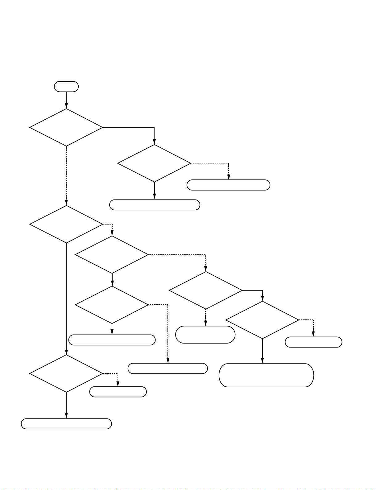
9. No line is connected. (ISDN)
system setup proper? (For bonding
connection, check that address of ISDN line
connected to local terminal is properly set
to second page of ISDN set menu
SS-09
Are contents of
setting in dial list and
on the incoming
side.)
YES
NO
Set it properly.
communication terminal
Are
and ISDN unit properly
connected?
YES
Does STATUS
lamp of ISDN unit blinks
in green?
YES
Do STATUS 1 to 6
lamps of ISDN unit light in
yellow proportionally to number of
connected lines when line is connected
to ISDN unit by number of
connected lines?
YES
NO
Connect them properly.
NO
Communication terminal or ISDN unit
is defective.
NO
ISDN unit or network is defective.
PCS-1/PCS-1P
Communication terminal is defective.
2-11
Page 42

10. No line is connected. (LAN)
SS-10
Are the setting
contents of the dial list and
system setup correct?
YES
Are the
connection of LAN
cable, and the setting of
IP address and net
mask correct?
YES
Communication terminal is defective.
NO
Set it properly.
NO
Connect and set correctly.
2-12
PCS-1/PCS-1P
Page 43
11. No voice can be heard from the remote side after a line is connected.
SS-11
Is the volume of the
main unit turned down?
NO
Is the microphone
of the other end of the
line turned on?
YES
Is the
connection of the
voice signal between the
main unit and monitor
TV correct?
YES
YES
Turn up the volume.
NO
Ask the other end of the line to
turn on the microphone.
NO
Connect it properly.
PCS-1/PCS-1P
Is the volume of the
monitor TV turned down?
NO
Communication terminal is defective.
YES
Turn up the volume of the
monitor TV .
2-13
Page 44
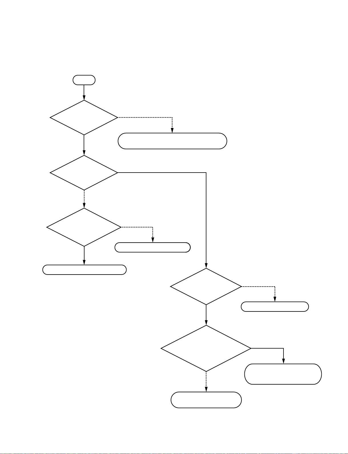
12. No voice can be transmitted to the remote side after a line is connected.
SS-12
Is AUX set to
“Input switching” of audio
set menu?
NO
Is Internal set in
“Microphone selection” of
audio set menu?
YES
set in “Microphone selection”
output from connected
Communication terminal is defective.
YES
Communication terminal is defective.
NO
Is DSB AUX IN
of audio set menu?
YES
Is audio signal
equipment?
YES
Is audio signal
output from connected
equipment?
YES
NO
NO
NO
Connected equipment is defective.
Is PCS-A1/PCS-A300
microphone connected?
NO
Connect PCS-A1/
PCS-A300 microphone.
YES
Is microphone OFF
canceled?
YES
NO
Set microphone to ON.
Is microphone OFF
canceled?
Set microphone to ON.
YES
Communication terminal is defective.
2-14
NO
Connected equipment is defective.
Communication terminal, data solution
box, or PCS-A1/PCS-A300 microphone
is defective.
PCS-1/PCS-1P
Page 45
13. No video input (object, AUX1, or AUX2) image can be displayed. The image of a camera is
displayed.
SS-13
Is video input
properly set?
YES
Is “Object” selected
as video input?
NO
Is video signal output
from equipment connected
to AUX1 and AUX2
terminals?
YES
Communication terminal is defective.
NO
Press input selector button of remote controller
and select input properly using joystick.
YES
NO
Connected equipment is defective.
PCS-1/PCS-1P
Is power
PCS-DS150 on?
YES
Does
obstacle exist
between infrared light
emitter of PCS-DS150 and infrared
photosensor of
communication
terminal?
NO
Communication terminal or
PCS-DS150 is defective.
NO
Turn on power of PCS-DS150.
YES
Remove obstacle and adjust so
that light emitter is linear with
photosensor.
2-15
Page 46

14. An image on the remote side is not displayed after a line is connected.
SS-14
Is the video
signal output connected
from VIDEO OUT MONITOR
MAIN or VIDEO OUT
AUX?
YES
Can the
display be switched
using the other side/this side
button on the remote
controller?
NO
Connect correctly.
NO
YES
Is the image
of the other end
displayed when a connection
is made with another
communication
end?
YES
Check the terminal of the other end.
Failure of the communication terminal
NO
Communication terminal is defective.
2-16
PCS-1/PCS-1P
Page 47
15. An image cannot be transmitted to the remote side after a line is connected.
SS-15
Is the setting of the video
signal input correct?
YES
Is the video signal
output from the equipment
that is connected?
YES
Can the video
signal be sent to the other
end when a connection is made
with another communication
end?
YES
NO
Press the input selector button on the
remote controller and select the input
correctly using the joystick.
NO
Failure of the equipment that is connected
NO
Communication terminal is defective.
PCS-1/PCS-1P
Check the terminal of the other end.
2-17
Page 48

2-3. Operation Log
PCS1/1P has a function that outputs the internal processing history, between the connection and
disconnection of a line, to the commercial PC connected to the outside and a function that saves the latest
history of 1M byte in a memory stick (refer to the saving of system log on page 56).
Operation log using commercial PC (1)
Connect an AUX CONTROL terminal and PC to the right on the front panel of PCS-1/1P.
Start the power of PCS-1/1P and PC.
(RS-232C cross cable)
ON LINE POWER LAN ALERT
PCS-1/1P
Personal computer
Activate accessory software “Hyper terminal” of PC Windows 95/98/2000/XP and set the communication
format as described below.
Transmission rate: 38,400 bits/s
Data length: 8 bits
Stop bit: 2 bits
Parity bit: None
The procedure for HYPERTRM activation, communication format setting, and operation log execution is
described on the next page and later.
. WINDOWS 95/98/2000/XP is the registered trademark of Microsoft Corporation.
. For WINDOWS 2000/XP, the procedure is “Start menu” → “Program” → “Accessory” →
“Communication” → “Hyper terminal”.
Note: In a hyper terminal, only 500 lines can be logged. For long-time logging, use other terminal
emulators.
2-18
PCS-1/PCS-1P
Page 49

(1) Click “Start menu”, “Accessory”, “Communication”, and then “Hyper terminal”.
(2) Enter “VT100” in “Name (N)”, select any icon, and click the “OK” button.
PCS-1/PCS-1P
2-19
Page 50

(3) Select “COM1” in “Connect To” and click the “OK” button.
(4) Set the baud rate as described below and click the “OK” button.
Bit/s: 38,400
Data bit: 8
Parity: None
Stop bit: 2
Flow control: Xon/Xoff
2-20
PCS-1/PCS-1P
Page 51

(5) Click “Capture Text” from a “Transfer” menu.
(6) Set the saving place and name of a log file and click “Start”.
PCS-1/PCS-1P
2-21
Page 52

(7) After logging, click “Stop” from “Capture Text” in a “Transfer” menu.
(8) Double-click the extracted log file to view a log.
2-22
PCS-1/PCS-1P
Page 53
Operation log using commercial PC (2)
When PCS-1/1P is connected to LAN, a log can be extracted from PCS-1/1P using telnet with PC
connected to LAN.
Even when PCS-1/1P is not connected to LAN, a log can be extracted from PCS-1/1P using telnet by
connecting the 100BASE-TX/10BASE-T terminal on the rear panel of PCS-1/1P and the LAN terminal
of PC directly using a LAN cross cable.
First, connect PCS-1/1P and PC to LAN, or connect them directly using a cross cable and set LAN of IP.
After that, transmit ping from PC to PCS-1/1P and confirm that a reply is returned from PCS-1/1P.
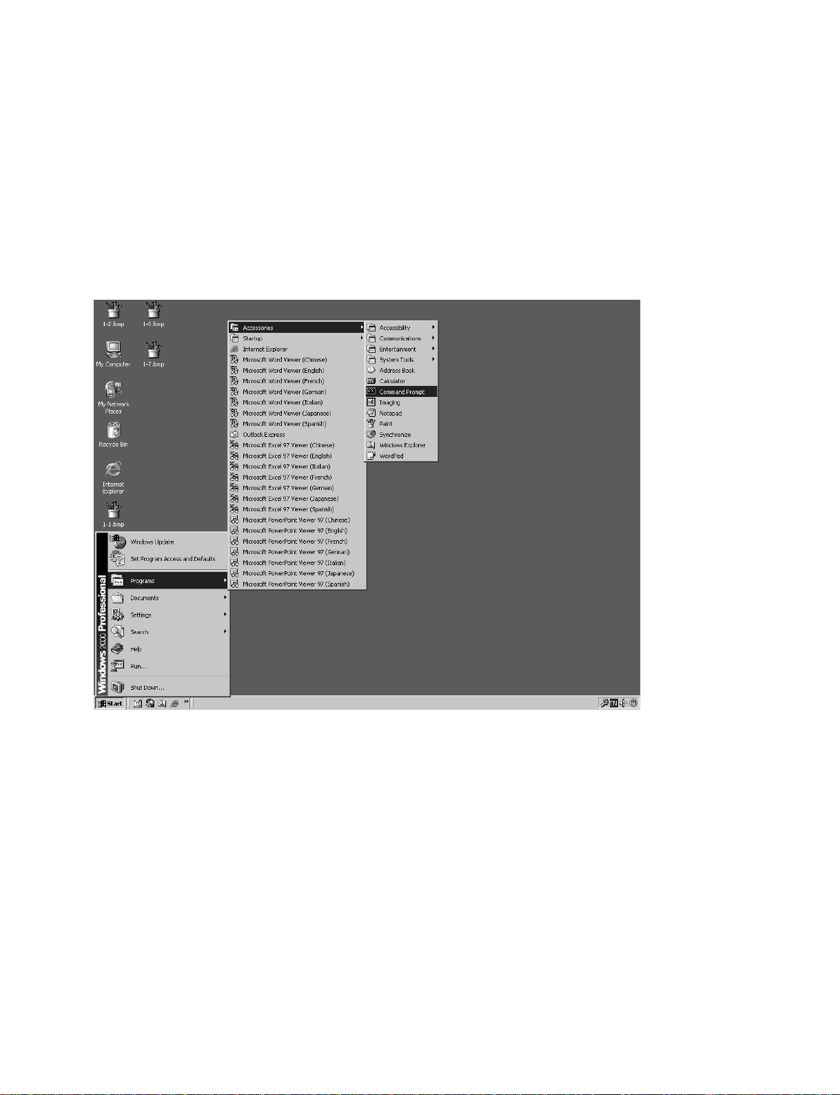
(1) Click “Command prompt” from “Start menu”.
PCS-1/PCS-1P
2-23
Page 54

(2) Enter ping, and then enter the IP address of PCS-1/1P after spacing out. Press the [Enter] key and
confirm that a reply is returned. After confirmation, close the command prompt.
(3) Click “Start menu”, “Accessory”, “Communication”, and then “Hyper terminal”.
2-24
PCS-1/PCS-1P
Page 55

(4) Enter “LAN” in “Name:”, select any icon, and click the “OK” button.
(5) Select “TCP/IP (Winsock)” in “Connect To”, enter the IP address of PCS-1/1P in “Host address:”,
and click the “OK” button.
PCS-1/PCS-1P
2-25
Page 56

(6) Click “Capture Text” from a “Transfer” menu.
(7) Set the saving place and name of a log file and click the “Start” button.
Example of name: PCS-1LOG.txt
2-26
PCS-1/PCS-1P
Page 57

(8) The message below is displayed on the hyper terminal screen.
PCS-1 Telnet Server
login:
Enter sonypcs and press the Enter key. Password: is then displayed. Press the Enter key again. A
log begins to be extracted.
(9) After log extraction is completed, click “Stop” from “Capture Text” in a “Transfer” menu.
(10)Double-click the extracted log file to view a log.
PCS-1/PCS-1P
2-27
Page 58
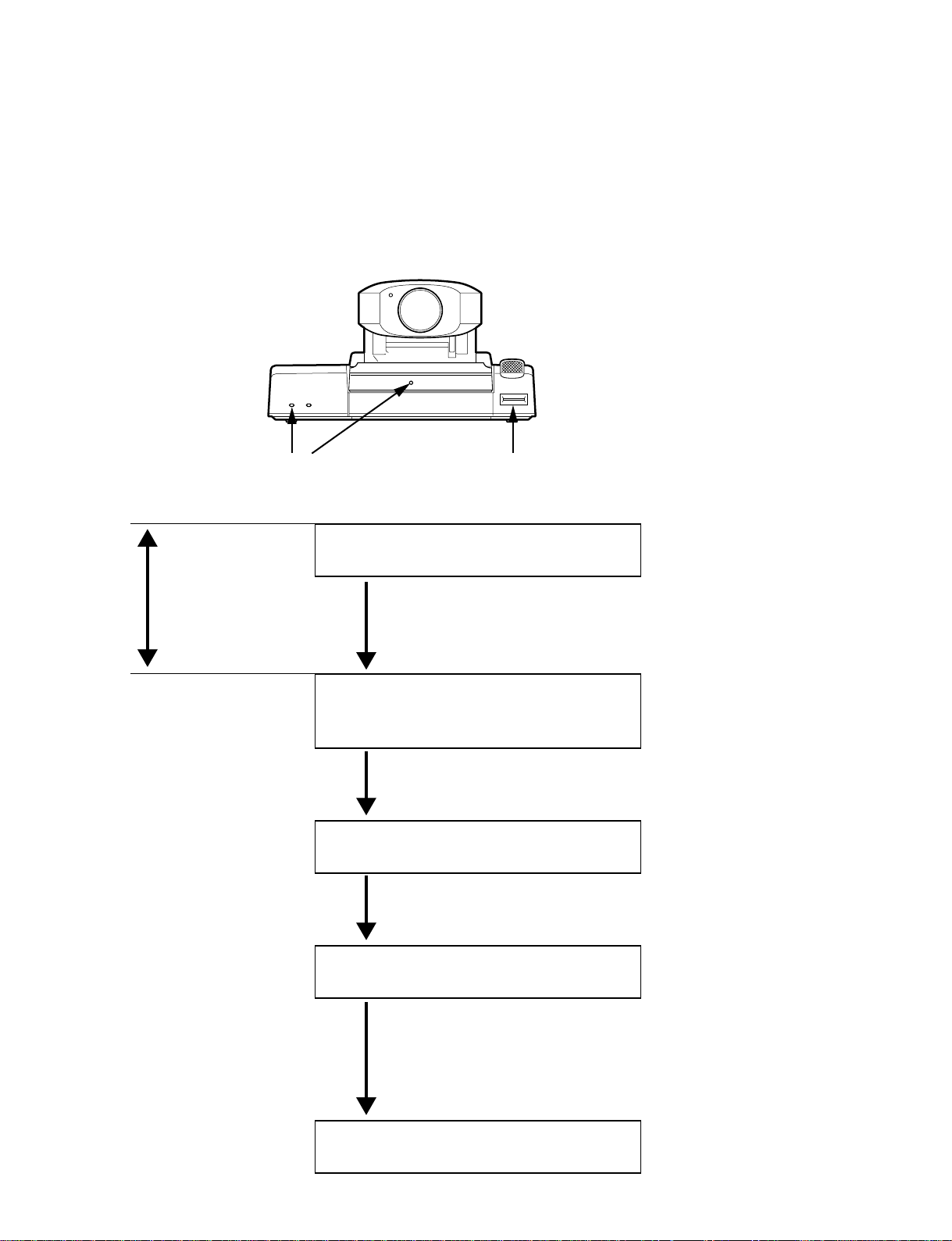
2-4. Updating of Software
The software of the main unit may be updated for improvement in a function.
Two methods are available for updating.
2-4-1. Updating Using Memory Stick
POWER lamp (green) Memory Stick slot
Take care that the
power is not
absolutely turned off
in this while.
Software may not be
able to be updated.
Turn off the power switch on the side panel of
the main unit.
Insert a Memory Stick.
Turn on the power switch.
The POWER lamp (green) lights.
The loader execution screen is displayed.
A launcher menu is displayed on the monitor
television.
Push in a Memory Stick once and then take out it.
Select “Set” and confirm “Host version” in a
device information menu.
2-28
Return to the launcher menu and turn off the power switch
on the rear panel of this unit.
Turn on the power switch again and reconfirm
“Host version”.
PCS-1/PCS-1P
Page 59
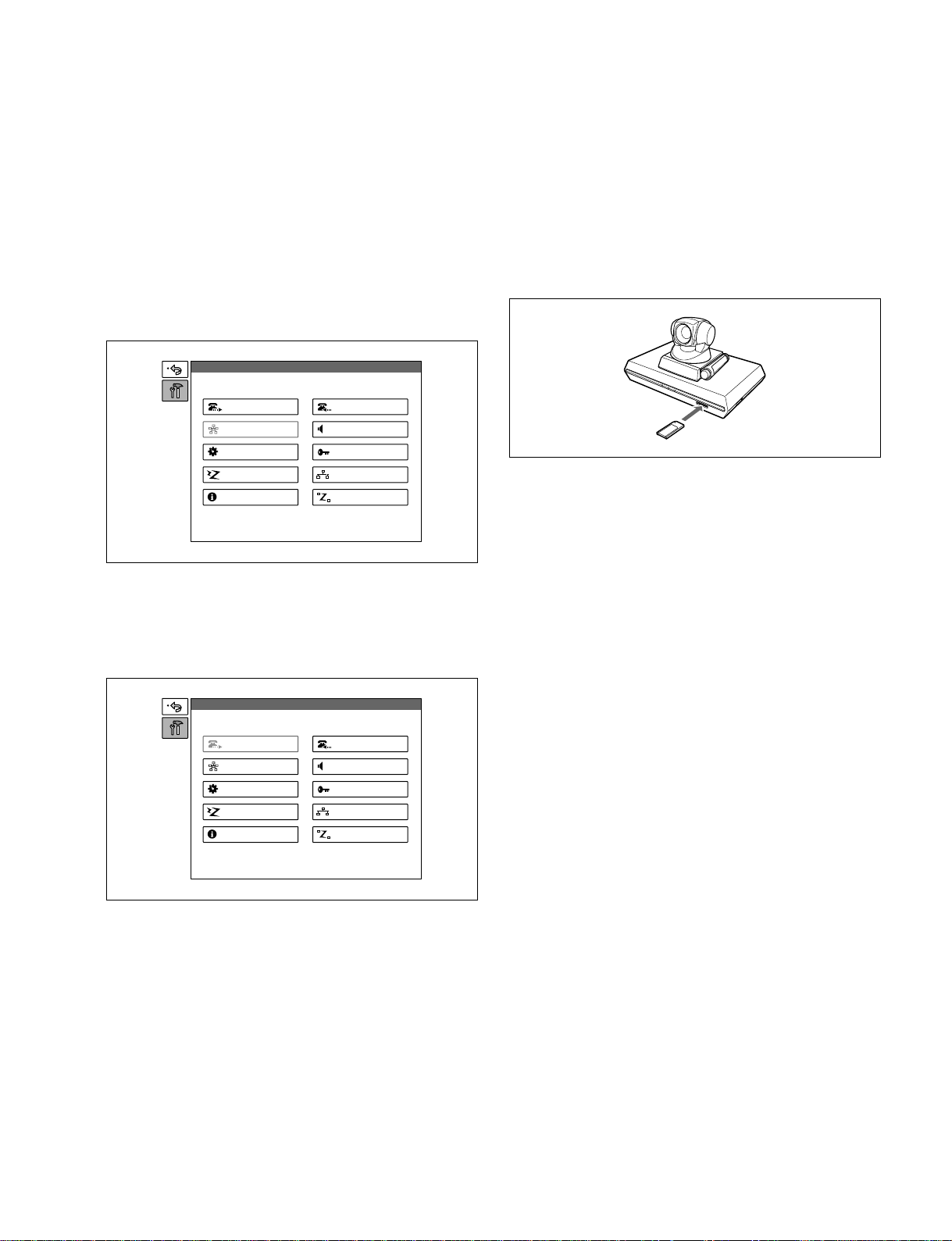
2-5. Service Mode
In the service menu of PCS-1/1P, data can be saved in the
Memory Stick of an address book using a commercial
Memory Stick or read from a Memory Stick (overwritten
in the current data).
1. Continuously press the menu button of a remote
controller and display a “Set” menu including
“Outgoing” and “Incoming”.
Setup
For saving of an address book, loading of an
address book, saving of application, saving of a
communication log, saving of a system log,
saving of setting, and loading of setting
1. Display a service menu.
2. Insert the Memory Stick, in which data can be written
or in which the required contents have been already
recorded, into a Memory Stick slot.
Dial
Multipoint
General
ISDN
Information
Answer
Audio
Administrator
LAN
Status
2. Press the → button of a remote controller and select
“Outgoing”. Enter “7” and “2” sequentially using the
numeric key of a remote controller without pressing
the decide button and display the service menu.
Setup
Dial
Multipoint
General
ISDN
Information
Answer
Audio
Administrator
LAN
Status
n
To cancel the service mode, select “Cancel” using ↑, ↓, ←,
and → buttons of a remote controller and press the decide
button, or press the return button of a remote controller.
The current display returns to a set menu.
PCS-1/PCS-1P
3. Select the function, which you want to execute, using
↑, ↓, ←, and → buttons of a remote controller and
press the decide button.
4. A confirmation message on whether to execute the
function is displayed. To execute, select “OK” and
press the decide button. To cancel execution, select
“Cancel” and press the decide button.
5. After execution or cancellation, the current display
returns to a service menu.
6. Push in the Memory Stick once and take out it.
For erasure of an address book and setting
1. Display a service menu.
2. Select the function, which you want to execute, using
↑, ↓, ←, and → buttons of a remote controller and
press the decide button
3. A confirmation message on whether to execute the
function is displayed. To execute, select “OK” and
press the decide button. To cancel execution, select
“Cancel” and press the decide button.
4. After execution or cancellation, the current display
returns to a service menu.
For system reset
1. Display a service menu.
2. Select “System reset” using ↑, ↓, ←, and → buttons of
a remote controller and press the decide button
3. A confirmation message on whether to execute is
displayed. To execute, select “OK” and press the
decide button. To cancel execution, select “Cancel”
and press the decide button.
4. After execution, a launcher menu is displayed. After
cancellation, the current display returns to a service
menu.
2-29
Page 60

For loading of application
1. Display a service menu.
2. Insert the Memory Stick, in which the application
software of the version to be loaded is recorded, into a
Memory Stick slot.
3. Select “Load application” using ↑, ↓, ←, and →
buttons of a remote controller and press the decide
button.
4. A confirmation message on whether to execute is
displayed.
5. To execute, select “OK” and press the decide button.
The screen display during loader execution then
appears. After completion, a launcher menu is
displayed. To cancel execution, select “Cancel” and
press the decide button. The current display returns to
a service menu.
6. Push in the Memory Stick once and take out it.
n
Do not turn off the power or take out a Memory Stick until
the launcher menu is displayed.
For command input
1. Display a service menu.
2. Select “Command” using ↑, ↓, ←, and → buttons of a
remote controller and press the decide button.
A key guidance is then displayed.
3. Enter the commands in a command list from a remote
controller.
m
. To set two or more commands, put a one-character
blank between the commands and then enter them.
. Set only one type of LAN interface. If not, the LAN
interface does not operate normally.
4. Select “Save” using ↑, ↓, ←, and → buttons of a
remote controller and press the decide button.
A set menu is then displayed.
5. When a LAN interface is set (including the case where
the setting is returned to the initial value), restart the
main unit using the power switch of a communication
terminal.
Contents of functions
1) Commands
The internal operation mode of the main unit is
changed for a test and service.
Command list
Command
100F
Sets a LAN interface to the 100BASE
Contents
full-duplex mode.
100H
Sets a LAN interface to the 100BASE
half-duplex mode.
10F
Sets a LAN interface to the 10BASE fullduplex mode.
10H
Sets a LAN interface to the 10BASE
half-duplex mode.
TOS1 to
TOS255
Sets the Type Of Service (TOS) bit value
to a transmission packet.
Consult the network administrator for
the set value.
Blank (The
input value
above is
cleared.)
Set using an initial value.
The LAN interface mode is Auto
Negotiation.
Reception packet loss indicator
display ON
TOS0
m
. To set two or more commands, put a one-character blank
between the commands.
. Set only one type of LAN interface. If not, the LAN
interface does not operate normally.
. The enabled command can be confirmed in a command
column at all times.
. Do not enter commands other than shown in a command
list. The internal operation mode may be changed in this
case.
To stop setting
Select “Cancel” using ↑, ↓, ←, and → buttons of a remote
controller and press the decide button, or press the return
button of a remote controller.
n
Do not enter commands other than shown in a command
list. The internal operation mode may be changed in this
case.
2-30
PCS-1/PCS-1P
Page 61

2) Saving of address book
All contents of an address book are recorded and saved
in a Memory Stick. After execution, a file is created in
the area below in the Memory Stick.
¥MSSONY¥PRO¥TVCONF¥LIST¥PCS_DLST.CSV
This file can be edited using Microsoft Excel. Do not
change the file name.
3) Loading of address book
The contents of an address book (the file above in the
folder described above) recorded in a memory stick are
written in the address book of the main unit.
The contents cannot be returned to the former setting
after they are rewritten.
4) Erasure of address book
All contents of an address book in the main unit are
erased.
The contents cannot be returned to the former setting
after they are erased.
5) Saving of application
The software of the main unit is saved in a Memory
Stick. However, an MCU option is not saved in a
Memory Stick. MCU software or LAN software is
required separately.
6) Saving of communication log
The communication log recorded in the main unit is
recorded and saved in a Memory Stick. A maximum
of 500 latest logs are recorded in the main unit. After
execution, a file is created in the area below in a
Memory Stick.
¥MSSONY¥PRO¥TVCONF¥LOG¥PCS_LOG.CSV
This file can be edited using Microsoft Excel.
7) Saving of system log
A debug log is recorded and saved in a Memory Stick.
A maximum of 1M byte log is recorded and saved.
After execution, a file is created in the area below in a
Memory Stick.
¥MSSONY¥PRO¥TVCONF¥DEBUG¥PCS_DEB.TXT
This file can be edited using Microsoft Memo Pad,
Word Pad, or Word.
8) Saving of setting
All set information items in a set menu are recorded
and saved in a Memory Stick. After execution, a file
is created in the area below in a memory stick.
¥MSSONY¥PRO¥TVCONF¥SETUP¥PCS_STUP.CSV
This file can be edited using Microsoft Excel.
9) Loading of setting
The set information
(¥MSSONY¥PRO¥TVCONF¥SETUP¥PCS_STUP.CSV)
recorded in a Memory Stick is overwritten in the set
menu of the main unit. After execution, the screen
disappears once, and a launcher menu is displayed in
the same way as after the power is turned on.
The set information cannot be returned to the former
setting after it is rewritten.
10) Erasure of setting
All information items, in a set menu, set to the main
unit are erased. After execution, the screen disappears
once, and a set wizard is displayed in the same way as
when the power is turned on first.
11) Loading of application
The software of the main unit recorded in a Memory
Stick is loaded.
12) System reset
Software reset is applied to the main unit. After
execution, the screen disappears once, and a launcher
menu is displayed in the same way as after the power
is turned on.
PCS-1/PCS-1P
2-31
Page 62

Page 63

3-1. Connection via Hub
Example of system
Section 3
Compatibility in LAN Network
LAN1
Teleconference
terminal A
192.100.10.10
HUB
LAN2
Teleconference
terminal B
192.100.10.20
When a call is initiated from teleconference terminal A to teleconference terminal B.
1. The LAN set menu of teleconference terminal B is set as described below.
DHCP mode: OFF
Host name: Enter any name.
IP address: Local IP address (192.100.10.20)
Network mask: Depends on a network. Usually, set to 255.255.255.0.
Gateway address: Blank
DNS address: Blank
Gatekeeper used: OFF
Gatekeeper address: Blank
User name: Blank
User number: Blank
SNMP service: OFF
Trap transmission destination: Blank
Community name: public
Description of device: Videoconference Device
Installation place: Blank
Contact of administrator: Blank
NAT setting: OFF
NAT address: Blank
Packet retransmission request: Blank
Optimum rate control: OFF (Set to ON when a packet loss occurs frequently.)
Port number used: Specified value (Set to “User setting” when a port number is specified
by the network administrator.)
TCP port number: 2253 (Enter the port number specified by the network administrator
when the port number used is set to “User setting”.)
UDP port number: 49152 (Enter the port number specified by the network administrator
when the port number used is set to “User setting”.)
2. Confirm that the IP address displayed in the launcher menu of teleconference terminal B is
192.100.10.20.
PCS-1/PCS-1P
3-1
Page 64

3. The LAN set menu of teleconference terminal A is set as described below.
DHCP mode: OFF
Host name: Enter any name.
IP address: Local IP address (192.100.10.10)
Network mask: Depends on a network. Usually, set to 255.255.255.0.
Gateway address: Blank
DNS address: Blank
Gatekeeper used: OFF
Gatekeeper address: Blank
User name: Blank
User number: Blank
SNMP service: OFF
Trap transmission destination: Blank
Community name: public
Description of device: Videoconference Device
Installation place: Blank
Contact of administrator: Blank
NAT setting: OFF
NAT address: Blank
Packet retransmission request: Blank
Optimum rate control: OFF (Set to ON when a packet loss occurs frequently.)
Port number used: Specified value (Set to “User setting” when a port number is specified
by the network administrator.)
TCP port number: 2253 (Enter the port number specified by the network administrator
when the port number used is set to “User setting”.)
UDP port number: 49152 (Enter the port number specified by the network administrator
when the port number used is set to “User setting”.)
4. Confirm that the IP address displayed in the launcher menu of teleconference terminal A is
192.100.10.20.
5. Enter LAN in the address book of teleconference terminal A for a line type, IP address 192.100.10.20
of teleconference terminal B in it for an IP address, and other required items. After that, register
teleconference terminal B in the address book and initiate a call. Or set LAN for a line type and IP
address 192.100.10.20 of teleconference terminal B for an IP address by dialing, and then initiate a
call.
3-2
PCS-1/PCS-1P
Page 65

3-2. Connection via Router
Example of system
LAN1 LAN2
192.100.10.1 WAN 192.100.20.1
Router Router
Teleconference
terminal A
192.100.10.10
Teleconference
terminal B
192.100.20.20
When a call is initiated from teleconference terminal A to teleconference terminal B.
1. The LAN set menu of teleconference terminal B is set as described below.
DHCP mode: OFF
Host name: Enter any name.
IP address: Local IP address (192.100.20.20)
Network mask: Depends on a network. Usually, set to 255.255.255.0.
Gateway address: 192.100.20.1
DNS address: Blank
Gatekeeper used: OFF
Gatekeeper address: Blank
User name: Blank
User number: Blank
SNMP service: OFF
Trap transmission destination: Blank
Community name: public
Description of device: Videoconference Device
Installation place: Blank
Contact of administrator: Blank
NAT setting: OFF
NAT address: Blank
Packet retransmission request: Blank
Optimum rate control: OFF (Set to ON when a packet loss occurs frequently.)
Port number used: Specified value (Set to “User setting” when a port number is specified
by the network administrator.)
TCP port number: 2253 (Enter the port number specified by the network administrator
when the port number used is set to “User setting”.)
UDP port number: 49152 (Enter the port number specified by the network administrator
when the port number used is set to “User setting”.)
2. Confirm that the IP address displayed in the launcher menu of teleconference terminal B is
192.100.20.20.
PCS-1/PCS-1P
3-3
Page 66

3. The LAN set menu of teleconference terminal A is set as described below.
DHCP mode: OFF
Host name: Enter any name.
IP address: Local IP address (192.100.10.10)
Network mask: Depends on a network. Usually, set to 255.255.255.0.
Gateway address: 192.100.10.1
DNS address: Blank
Gatekeeper used: OFF
Gatekeeper address: Blank
User name: Blank
User number: Blank
SNMP service: OFF
Trap transmission destination: Blank
Community name: public
Description of device: Videoconference Device
Installation place: Blank
Contact of administrator: Blank
NAT setting: OFF
NAT address: Blank
Packet retransmission request: Blank
Optimum rate control: OFF (Set to ON when a packet loss occurs frequently.)
Port number used: Specified value (Set to “User setting” when a port number is specified
by the network administrator.)
TCP port number: 2253 (Enter the port number specified by the network administrator
when the port number used is set to “User setting”.)
UDP port number: 49152 (Enter the port number specified by the network administrator
when the port number used is set to “User setting”.)
4. Confirm that the IP address displayed in the launcher menu of teleconference terminal A is
192.100.10.10.
5. Enter LAN in the address book of teleconference terminal A for a line type, IP address 192.100.20.20
of teleconference terminal B in it for an IP address, and other required items. After that, register
teleconference terminal B in the address book and initiate a call. Or set LAN for a line type and IP
address 192.100.20.20 of teleconference terminal B for an IP address by dialing, and then initiate a
call.
3-4
PCS-1/PCS-1P
Page 67

3-3. Connection via DHCP
Example of system
LAN1
Teleconference
terminal A
DHCP
server A
Router Router
DHCP
server B
Teleconference
LAN2
terminal B
When a call is initiated from teleconference terminal A to teleconference terminal B.
1. The LAN set menu of teleconference terminal B is set as described below.
DHCP mode: ON
Host name: Enter any name.
IP address: Blank
Network mask: Blank
Gateway address: Blank
DNS address: Blank
Gatekeeper used: OFF
Gatekeeper address: Blank
User name: Blank
User number: Blank
SNMP service: OFF
Trap transmission destination: Blank
Community name: public
Description of device: Videoconference Device
Installation place: Blank
Contact of administrator: Blank
NAT setting: OFF
NAT address: Blank
Packet retransmission request: Blank
Optimum rate control: OFF (Set to ON when a packet loss occurs frequently.)
Port number used: Specified value (Set to “User setting” when a port number is specified
by the network administrator.)
TCP port number: 2253 (Enter the port number specified by the network administrator
when the port number used is set to “User setting”.)
UDP port number: 49152 (Enter the port number specified by the network administrator
when the port number used is set to “User setting”.)
2. Confirm that the IP address displayed in the launcher menu of teleconference terminal B is
192.100.20.20.
PCS-1/PCS-1P
3-5
Page 68

3. The LAN set menu of teleconference terminal A is set as described below.
DHCP mode: ON
Host name: Enter any name.
IP address: Blank
Network mask: Blank
Gateway address: Blank
DNS address: Blank
Gatekeeper used: OFF
Gatekeeper address: Blank
User name: Blank
User number: Blank
SNMP service: OFF
Trap transmission destination: Blank
Community name: public
Description of device: Videoconference Device
Installation place: Blank
Contact of administrator: Blank
NAT setting: OFF
NAT address: Blank
Packet retransmission request: Blank
Optimum rate control: OFF (Set to ON when a packet loss occurs frequently.)
Port number used: Specified value (Set to “User setting” when a port number is specified
by the network administrator.)
TCP port number: 2253 (Enter the port number specified by the network administrator
when the port number used is set to “User setting”.)
UDP port number: 49152 (Enter the port number specified by the network administrator
when the port number used is set to “User setting”.)
4. Confirm that the IP address displayed in the launcher menu of teleconference terminal A is
192.100.10.10.
5. Enter LAN in the address book of teleconference terminal A for a line type, the IP address of
teleconference terminal B in it for an IP address, and other required items. After that, register
teleconference terminal B in the address book and initiate a call. Or set LAN for a line type and the
IP address of teleconference terminal B for an IP address by dialing, and then initiate a call.
3-6
PCS-1/PCS-1P
Page 69

3-4. Connection via Gatekeeper
Example of system
LAN1 LAN2
192.100.10.1 192.100.20.1
Router Router
Teleconference
terminal A
192.100.10.10
User name:
PCS1A
User number:
100
Gatekeeper
192.100.10.20
Teleconference
terminal B
192.100.20.20
User name:
PCS1B
User number:
200
When a call is initiated from teleconference terminal A to teleconference terminal B.
1. The LAN set menu of teleconference terminal B is set as described below.
DHCP mode: OFF
Host name: Enter any name.
IP address: Local IP address (192.100.20.20)
Network mask: Depends on a network. Usually, set to 255.255.255.0.
Gateway address: 192.100.20.1
DNS address: Blank
Gatekeeper used: ON
Gatekeeper address: 192.100.10.20
User name: Enter any name. (Example: PCS1B)
User number: Enter any number. (Example: 200)
SNMP service: OFF
Trap transmission destination: Blank
Community name: public
Description of device: Videoconference Device
Installation place: Blank
Contact of administrator: Blank
NAT setting: OFF
NAT address: Blank
Packet retransmission request: Blank
Optimum rate control: OFF (Set to ON when a packet loss occurs frequently.)
Port number used: Specified value (Set to “User setting” when a port number is specified
by the network administrator.)
TCP port number: 2253 (Enter the port number specified by the network administrator
when the port number used is set to “User setting”.)
UDP port number: 49152 (Enter the port number specified by the network administrator
when the port number used is set to “User setting”.)
2. Confirm that the IP address displayed in the launcher menu of teleconference terminal B is
192.100.20.20.
3. Confirm that Registration Confirm is displayed at the bottom of page 2/5 in the LAN set menu of
teleconference terminal B.
PCS-1/PCS-1P
3-7
Page 70

4. The LAN set menu of teleconference terminal A is set as described below.
DHCP mode: OFF
Host name: Enter any name.
IP address: Local IP address (192.100.10.10)
Network mask: Depends on a network. Usually, set to 255.255.255.0.
Gateway address: 192.100.10.1
DNS address: Blank
Gatekeeper used: ON
Gatekeeper address: 192.100.10.20
User name: Enter any name. (Example: PCS1A)
User number: Enter any number. (Example: 100)
SNMP service: OFF
Trap transmission destination: Blank
Community name: public
Description of device: Videoconference Device
Installation place: Blank
Contact of administrator: Blank
NAT setting: OFF
NAT address: Blank
Packet retransmission request: Blank
Optimum rate control: OFF (Set to ON when a packet loss occurs frequently.)
Port number used: Specified value (Set to “User setting” when a port number is specified
by the network administrator.)
TCP port number: 2253 (Enter the port number specified by the network administrator
when the port number used is set to “User setting”.)
UDP port number: 49152 (Enter the port number specified by the network administrator
when the port number used is set to “User setting”.)
5. Confirm that the IP address displayed in the launcher menu of teleconference terminal A is
192.100.10.10.
6. Confirm that Registration Confirm is displayed at the bottom of page 2/5 in the LAN set menu of
teleconference terminal A.
7. Enter LAN in the dial list of teleconference terminal A for a line type, user name PCS1B or user
number 200 of teleconference terminal B in it for an IP address, and other required items. After that,
register teleconference terminal B and initiate a call. Or set LAN for a line type and user name
PCS1B or user number 200 of teleconference terminal B for an IP address by dialing, and then
initiate a call.
3-8
PCS-1/PCS-1P
Page 71

3-5. Connection via DHCP and Gatekeeper
Example of system
Router Router
LAN1 LAN2
Teleconference
terminal A
User name:
PCS1A
User number:
100
DHCP
server A
Gatekeeper
192.100.10.20
DHCP
server B
Teleconference
terminal B
User name:
PCS1B
User number:
200
When a call is initiated from teleconference terminal A to teleconference terminal B.
1. The LAN set menu of teleconference terminal B is set as described below.
DHCP mode: ON
Host name: Enter any name.
IP address: Blank
Network mask: Blank
Gateway address: Blank
DNS address: Blank
Gatekeeper used: ON
Gatekeeper address: 192.100.10.20
User name: Enter any name. (Example: PCS1B)
User number: Enter any number. (Example: 200)
SNMP service: OFF
Trap transmission destination: Blank
Community name: public
Description of device: Videoconference Device
Installation place: Blank
Contact of administrator: Blank
NAT setting: OFF
NAT address: Blank
Packet retransmission request: Blank
Optimum rate control: OFF (Set to ON when a packet loss occurs frequently.)
Port number used: Specified value (Set to “User setting” when a port number is specified
by the network administrator.)
TCP port number: 2253 (Enter the port number specified by the network administrator
when the port number used is set to “User setting”.)
UDP port number: 49152 (Enter the port number specified by the network administrator
when the port number used is set to “User setting”.)
2. Confirm that the IP address displayed in the launcher menu of teleconference terminal B is
192.100.20.20.
3. Confirm that Registration Confirm is displayed at the bottom of page 2/5 in the LAN set menu of
teleconference terminal B.
PCS-1/PCS-1P
3-9
Page 72

4. The LAN set menu of teleconference terminal A is set as described below.
DHCP mode: ON
Host name: Enter any name.
IP address: Blank
Network mask: Blank.
Gateway address: Blank
DNS address: Blank
Gatekeeper used: ON
Gatekeeper address: 192.100.10.20
User name: Enter any name. (Example: PCS1A)
User number: Enter any number. (Example: 100)
SNMP service: OFF
Trap transmission destination: Blank
Community name: public
Description of device: Videoconference Device
Installation place: Blank
Contact of administrator: Blank
NAT setting: OFF
NAT address: Blank
Packet retransmission request: Blank
Optimum rate control: OFF (Set to ON when a packet loss occurs frequently.)
Port number used: Specified value (Set to “User setting” when a port number is specified
by the network administrator.)
TCP port number: 2253 (Enter the port number specified by the network administrator
when the port number used is set to “User setting”.)
UDP port number: 49152 (Enter the port number specified by the network administrator
when the port number used is set to “User setting”.)
5. Confirm that the IP address displayed in the launcher menu of teleconference terminal A is
192.100.10.10.
6. Confirm that Registration Confirm is displayed at the bottom of page 2/5 in the LAN set menu of
teleconference terminal A.
7. Enter LAN in the dial list of teleconference terminal A for a line type, user name PCS1B or user
number 200 of teleconference terminal B in it for an IP address, and other required items. After that,
register teleconference terminal B and initiate a call. Or set LAN for a line type and user name
PCS1B or user number 200 of teleconference terminal B for an IP address by dialing, and then
initiate a call.
3-10
PCS-1/PCS-1P
Page 73

Section 4
Technical Data
4-1. PCS-1/1P Port Number Used
4-1-1. During Opposed Connection (Specified Value)
PCS-1 uses the port number below during opposed connection when the port number used in a LAN set
menu is set as “Specified value”.
Port number
RAS (PCS-1/1P) 2253 (when GK is used)
RAS (Gatekeeper) 1719 (when GK is used)
Q.931 (Outgoing) 2254
Q.931 (Incoming) 1720
H.245 2255 (Outgoing), 2254 (Incoming)
Audio RTP 49152
Audio RTCP 49153
Video RTP 49154
Video RTCP 49155
FECC RTP 49156
FECC RTCP 49157
Data conference RTP 49158
Data conference RTCP 49159
4-1-2. Opposed Connection (User Setting: When TCP port number is set to 3000
and UDP port number is set to 3100)
The port number that PCS-1/1P uses is determined by the value input to TCP and UDP port numbers
when the port number used in a LAN set menu is set as “User setting”. For example, PCS-1/1P uses the
port number below during opposed connection when a TCP port number is set to 3000 and when an UDP
port number is set to 3100.
Port number
RAS (PCS-1/1P) 3000 (when GK is used)
RAS (Gatekeeper) 1719 (when GK is used)
Q.931 (Outgoing) 3001
Q.931 (Incoming) 1720
H.245 3002 (Outgoing), 3001 (Incoming)
Audio RTP 3100
Audio RTCP 3101
Video RTP 3102
Video RTCP 3103
FECC RTP 3104
FECC RTCP 3105
Data conference RTP 3106
Data conference RTCP 3107
PCS-1/PCS-1P
4-1
Page 74

4-1-3. During Use of Internal MCU Function (Specified Value)
PCS-1/1P that operates as internal MCU uses the port number below when the port number used in a
LAN set menu is set as “Specified value”. The port number that a sub-terminal uses is the same as during
opposed connection.
Port number (at first point) Port number (at N’th point)
RAS (PCS-1/1P) 2253 (when GK is used) 2253 (when GK is used)
RAS (Gatekeeper) 1719 (when GK is used) 1719 (when GK is used)
Q931 (Outgoing) 2254 2254+2 x (N_1)
Q931 (Incoming) 1720 1720
H.245 2255 (Outgoing), 2254 (Incoming) 2255+2 x (N_1) (Outgoing), 2254 (Incoming)
Audio RTP 49152 49152+20 x (N_1)
Audio RTCP 49153 49153+20 x (N_1)
Video RTP 49154 49154+20 x (N_1)
Video RTCP 49155 49155+20 x (N_1)
FECC RTP 49156 49156+20 x (N_1)
FECC RTCP 49157 49157+20 x (N_1)
Data conference RTP 49158 49158+20 x (N_1)
Data conference RTCP 49159 49159+20 x (N_1)
4-1-4. During Use of Internal MCU Function (User Setting: When TCP port
number is set to 3000 and when UDP port number is set to 3100)
The port number that PCS-1/1P uses is determined by the value input to TCP and UDP port numbers
when the port number used in a LAN set menu is set as “User setting”. For example, PCS-1/1P that
operates as internal MCU uses the port number below during opposed connection when a TCP port
number is set to 3000 and when an UDP port number is set to 3100. The port number that a sub-terminal
uses is the same as during opposed connection.
Port number (at first point) Port number (at N’th point)
RAS (PCS-1/1P) 3000 (when GK is used) 3000 (when GK is used)
RAS (Gatekeeper) 1719 (when GK is used) 1719 (when GK is used)
Q931 (Outgoing) 3001 3001+2 x (N_1)
Q931 (Incoming) 1720 1720
H.245 3002 (Outgoing), 3001 (Incoming) 3002+2 x (N_1) (Outgoing), 3001 (Incoming)
Audio RTP 3100 3100+20 x (N_1)
Audio RTCP 3101 3101+20 x (N_1)
Video RTP 3102 3102+20 x (N_1)
Video RTCP 3103 3103+20 x (N_1)
FECC RTP 3104 3104+20 x (N_1)
FECC RTCP 3105 3105+20 x (N_1)
Data conference RTP 3106 3106+20 x (N_1)
Data conference RTCP 3107 3107+20 x (N_1)
4-2
PCS-1/PCS-1P
Page 75

4-2. Setting of PCS-1 and HUB
The initial setting of the PCS-1 is Auto.
In the Auto setting of the PCS-1, 10/100 can be selected automatically, however, Half/Full cannot be selected
automatically. Therefore, if the HUB is set to Full mode, a connection failure or packet loss occurs. The following table
shows an example of connection between the PCS-1 and Catalyst 2950. When the HUB is set to 100FULL or 10FULL,
change the setting of HUB or adjust the PCS-1 setting to HUB. Refer to “2-5. Service Mode” for the setting procedure of
the PCS-1.
Table of connection between PCS-1 and Catalyst 2950
PCS-1 setting AUTO 100FULL 100HALF 10FULL 10HALF
2950 settting
AUTO OK Packet loss OK Packet loss OK
100FULL Packet loss OK Packet loss Connection failure Connection failure
100HALF OK Packet loss OK Connection failure Connection failure
10FULL Packet loss Connection failure Connection failure OK Packet loss
10HALF OK Connection failure Connection failure Packet loss OK
PCS-1/PCS-1P
4-3
Page 76

Page 77

Page 78

PCS-1 (UC)
PCS-1P (CE) E
9-968-036-01
Sony Corporation 2003. 7 22
B&P Company ©2003
 Loading...