

Page 1
3-869-912-11 (1)
SCCP Software
Operating Instructions
Before operating the unit, please read this manual thoroughly and retain it for
future reference.
This manual describes the operations of the PCS-1 Video Communication
System when the PCSA-SC1 SCCP Software is installed in the system.
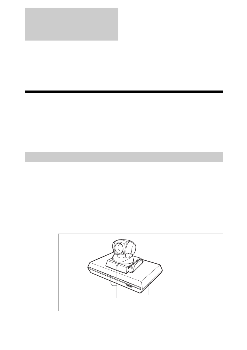
For details on the safety precautions and the original specifications of the Video
Communication System, read the Operating Instructions supplied with the
Video Communication System.
PCSA-SC1
© 2005 Sony Corporation
Page 2

Owner’s Record
The model and the serial numbers are
located at the rear. Record the serial number
in the space provided below. Refer to these
numbers whenever you call upon your Sony
dealer regarding this product.
Model No. PCSA-SC1
Serial No. ______________
Owner’s Record
2
Page 3

Table of Contents
Chapter 1: Installation and
Preparation
Using This Manual .............................6
Features ..............................................7
System Components ...........................8
Basic System Components ........... 8
Optional Equipment .....................9
System Connections .........................10
System Configuration via a LAN
..........................................10
Notes on Connections .................10
System Connection via a LAN ... 11
Preparing the System .......................12
Inserting Batteries into the Remote
Commander ................................12
Turning On/Off the TV Monitor
Together With the Communication
Terminal .....................................13
Installing the SCCP Software ..........14
Turning the System On/Off ..............15
Turning On .................................15
Standby Mode Function .............16
Setting the Video Communication
System to Standby Mode ............17
Turning Off .................................18
Adjusting the Volume on the TV
Monitor .......................................18
Displaying the Versions, etc. ......19
Using the Menu ................................20
Menu Configurations ..................20
Introduction of Menus ................ 21
Entering Characters ....................22
Chapter 2: Registration and
Setup for System
Administrators
Registering Local Information ........ 23
Opening the Setup Menu ........... 23
General Setup Menu .................. 24
Audio Setup Menu ..................... 26
LAN Setup Menu ....................... 27
Administrator Setup Menu ......... 29
Machine Information Menu ....... 30
Status Menu ............................... 30
Chapter 3: Daily
Videoconference
Starting a Conference by Calling a
Remote Party – NewCall ................. 32
Turning on the Power ................ 32
Using the Launcher Menu .......... 33
Calling a Remote Party Using Speed
Dial ......................................... 35
Calling a Remote Party by Entering
a Number in the Launcher Menu 36
Calling a Remote Party Registered
in the Phone Book ...................... 37
Calling a Remote Party Using the
Call History ................................ 39
Calling a Remote Party by Redialing
......................................... 40
Receiving a Call from a Remote Party
– Answer .......................................... 41
Putting a Call on Hold – Hold ......... 43
Ending the Conference – EndCall ... 44
Calling or Answering Another Remote
Party During Communication .......... 45
Calling Another Remote Party
During Communication ............. 45
3Table of Contents
Page 4

Answering a Call from Another
Remote Party During
Communication .......................... 46
Transferring a Call – Transfer/DirTrfr/
CFwdAll ...........................................47
Transferring a Call After
Confirmation of the Destination
Remote Party – Transfer ............ 47
Transferring a Call Without
Confirmation of the Destination
Remote Party – DirTrfr .............. 49
Transferring All Incoming Calls
– CFwdAll ..................................50
Parking a Call in the SCCP Server
– Park ...............................................51
Receiving a Call Directed to Another
Terminal – PickUp / GPickUp ......... 52
Receiving a Call Directed to
Another Terminal in Your Group
– PickUp ..................................... 52
Receiving a Call Directed to a
Terminal in Another Group
– GPickUp ..................................53
Conducting a Multipoint
Videoconference – Confrn/Join ....... 54
Starting a Multipoint
Videoconference – Confrn ......... 54
Having a Remote Party in Hold
Mode Join in the Conference
– Join .........................................56
Conducting a MeetMe Conference
– MeetMe ........................................57
Adjusting the Sound .........................58
Adjusting the Volume ................58
Cutting Off the Sound Momentarily
– Muting Function ...................... 58
Synchronizing Audio and Video
– Lip Sync Function ................... 59
Reducing Echo – Echo Canceler 59
Adjusting the Camera ......................60
Adjusting the Camera Angle and
Zoom .........................................60
Adjusting the Focus and Brightness
......................................... 62
Presetting the Angle and Zoom
Settings .......................................63
Recalling the Preset Angle and
Zoom Setting ..............................64
Selecting the Input Picture and Sound
................................................66
Switching the Displayed Picture
Between the Local and Remote
Pictures .......................................66
Selecting the Input Picture ..........66
Switching the Sound to Be Sent to
the Remote Party .........................67
Monitoring the Local Picture as a
Window Picture – PinP Feature .......68
Chapter 4: Videoconference
With Optional Equipment
Using Two Monitors – Dual Monitor
................................................69
Using Multiple Microphones ............72
Using the Communication Transducer
(CTE) ................................................74
Recording Audio During a Conference
................................................76
Sending Audio/Video from the External
Equipment to a Remote Party ...........77
Outputting Video Signals to External
Equipment ........................................79
Controlling the Remote System With
the Tone Signal – DTMF Transmission
................................................80
4 Table of Contents
Page 5

Appendix
Location and Function of Parts and
Controls ............................................81
PCS-P1/P1P Communication
Terminal .....................................81
PCS-C1/C1P Camera Unit .........83
PCS-R1 Remote Commander .....84
On Screen Messages ........................86
Troubleshooting ...............................88
Specifications ...................................90
PCSA-SC1 SCCP Software .......90
PCS-P1/P1P Communication
Terminal .....................................90
PCS-C1/C1P Camera Unit .........91
PCS-R1 Remote Commander .....91
PCS-AC195 AC Adaptor ...........91
Acceptable RGB Output Signals 92
Pin Assignment ..........................93
List of Port Numbers Used on the
PCSA-SC1 ..................................95
Videoconferencing Room Layout ....95
Camera Range ............................95
Installing the Communication
Terminal and Camera .................97
About a “Memory Stick” .................97
Glossary ...........................................99
Menu Configuration .......................101
5Table of Contents
Page 6

Chapter 1:
Installation and
Preparation
Using This Manual
The chapters cover the following contents;
please read the chapters that may be required
for your type of videoconference.
Chapter 1: Installation and
Preparation
This chapter guides you through the system
configuration and information required to
use your Video Communication System for
the first time. It shows you how to install and
connect your Video Communication
System, to turn the system on/off and how to
access basic on-screen menus.
Chapter 2: Registration and Setup for
System Administrator
This chapter describes how to register and
set up all the necessary items for system
administrators, using the on-screen menus.
message and troubleshooting lists,
specifications and glossaries.
Chapter 3: Daily Videoconference
This chapter guides you through the basic
operations and settings to conduct a
videoconference. You will learn how to
conduct a conference from start to finish. It
is recommended that this chapter be read by
participants in the videoconference.
Chapter 4: Videoconference With
Optional Equipment
This chapter shows advanced
videoconferencing using the optional
equipment.
Appendix
This chapter contains description of the
controls and connectors on the components
of the Video Communication System,
6 Using This Manual
Page 7

Features
This SCCP1) Software is designed for use
with the PCS-1/1P Video Communication
System. Install the SCCP Software in the
Video Communication System, and you can
conduct a videoconference using an SCCP
2)
on the network with simple
server
operations similar to a normal phone.
The following are the major features when
the SCCP software is installed in the Video
Communication System.
Supports ITU-T international
videoconferencing standard
The Video Communication System
complies with ITU-T Recommendations
defined by WTSC for easy connection with
remote parties overseas.
ITU: International Telecommunication
Union
WTSC: World Telecommunications
Standardization Committee
Versatile use withe a variety of
display units
The Video Communication System is
compact size, allowing easy installation on a
TV. The camera and the Communication
Terminal can be separately installed,
allowing for greater flexibility when using a
large-size plasma display, projector screen,
etc.
Three telephone lines and six calls
available
One PCS-1/1P system supports up to three
telephone lines. Up to six calls can be held
on a telephone line.
Chapter 1: Installation and Preparation
Functions of CallManager
supported
You can use the speed dials and phone book
or directory registered in the CallManager
with this system.
The use of the function keys (soft keys) at
the bottom of the monitor screen enables
similar functions to those of the IP phones of
Cisco Systems, Inc.
1) SCCP is an abbreviation of Skinny Client
Control Protocol.
2)The SCCP server supported by this system
is Cisco CallManager of Cisco Systems,
Inc.
Cisco and Cisco Systems are registered
trademarks of Cisco Systems, Inc. and/or
its affiliates in the U.S. and certain other
countries.
Dual monitor system
Two monitors can be connected to the
Communication Terminal, enabling the use
of one monitor for motion pictures, and the
other monitor for pictures from a computer
or still images.
Wide range of video/audio
compression format selectable
The Video Communication System supports
H.264, H.263 and H.261 for video
compression format, and G.722, G.729a,
G.728, G.723.1, G.711 for audio
compression format.
7Features
Page 8

System Components
Basic System Components
The basic system consists of the following components.
Unit Description
PCS-P1/P1P Communication
Term in al
Contains the video codec, audio codec, echo
canceler, network interfaces and system controller.
PCS-C1/C1P Camera Unit Composed of the camera and an integrated
PCS-R1 Remote Commander Used to operate the Communication Terminal and
PCS-AC195 AC adaptor Supplies power to the Communication Terminal.
PCSA-SC1
SCCP software
microphone.
Camera Unit.
Allows conduct of a videoconference using the
SCCP Server.
8 System Components
Page 9
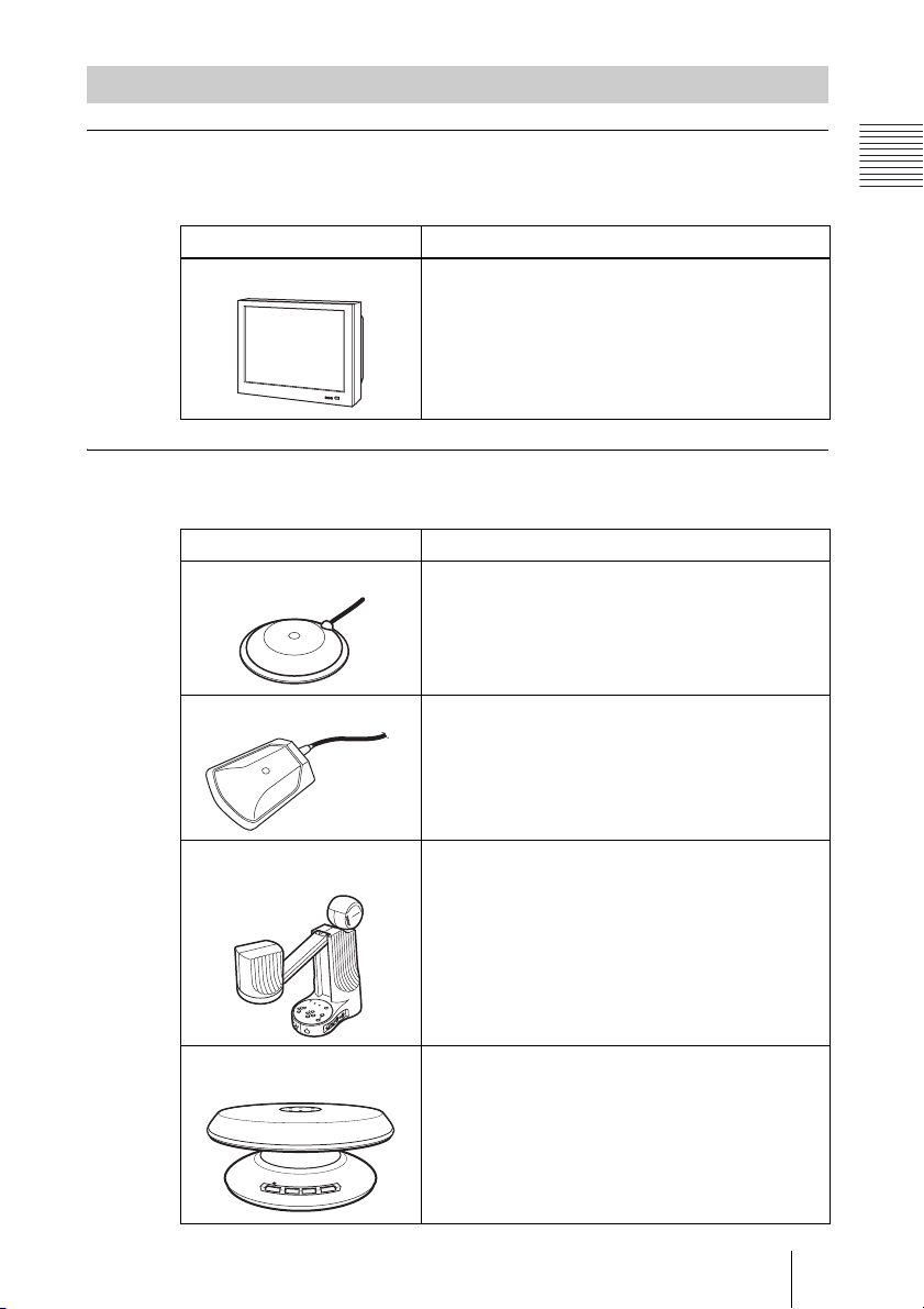
Optional Equipment
TV monitor
A TV or projector, etc. is required to monitor the images for videoconferencing
system.
Unit Description
TV, Projector, etc. Used as a monitor and speakers.
Optional equipment especially designed for use with the PCS-1/1P
The following optional devices are used to enhance your videoconference.
Unit Description
PCS-A1 Microphone Omni-directional microphone that picks up sound
relatively from all directions, allowing participants to
speak from any location. It is recommended to use in
a quiet situation.
Chapter 1: Installation and Preparation
PCSA-A3 Microphone Unidirectional microphone. It is recommended when
PCS-DS150/DS150P
Document Stand
CTE-600 Communication
Transducer
you want to pick up the voice of a speaker directed
toward the microphone.
Allows transmission of pictures to the
Communication Terminal by infrared signals without
connecting a cable.
Integrated microphone/speaker system suitable for
remote communication. The uni-directional
microphones pick up clear voice with minimum
background noise.
Moreover, the omni-directional speaker outputs
sound equally in all directions.
9System Components
Page 10

System Connections
By installing the PCSA-SC1 SCCP Software in the PCS-1/1P Video
Communication System, you can conduct a videoconference using an SCCP
server.
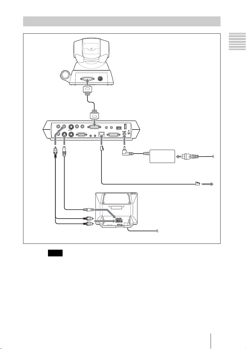
System Configuration via a LAN
System configuration
ON LINE POWER LAN ALERT
ON LINEPOWER LAN ALERT
1 PCS-P1/P1P Communication
Terminal
2 PCS-C1/C1P Camera Unit
3 PCS-R1 Remote Commander
4 PCSA-SC1 SCCP Software
5 TV monitor (not supplied)
6 SCCP server (not supplied)
Notes on Connections
• Be sure to turn off all the equipment before making any connections.
• Use the AC adaptor and the power cord supplied with this system only.
Never use the other AC adaptor or power cord.
• Insert the AC plug and DC plug of the AC adaptor securely as far as they will
go.
• Do not connect/disconnect a camera cable with the power on. Doing so may
damage the Camera Unit or Communication Terminal.
• For safety, do not connect the 100BASE-TX/10BASE-T connector to a
network that applies an excess voltage via the 100BASE-TX/10BASE-T
connector.
10 System Connections
Page 11
System Connection via a LAN
TERMINAL VISCA OUT
to TERMINAL
PCS-C1/C1P Camera Unit
Chapter 1: Installation and Preparation
PCS-P1/P1P
Communication
Terminal
to AUDIO
OUT
(MIXED)
AUDIO OUT
AUX
VIDEO OUT
AUX1–
VIDEO IN
–AUX2
MAIN–MONITOR–SUB
RGB OUT DSB
to VIDEO
OUT
AUDIO IN
MONITOR
MAIN
S-video
Audio
connecting
cable*
connecting
cable*
to S-video
to audio input
* supplied with the PCS-1/1P
** not supplied
Note
Do not connect a cable to the AUDIO OUT (MIXED) jack on the Communication
Terminal.
CAMERA UNIT MIC
12
input
IR OUT
Camera cable*
to CAMERA UNIT
(PLUG IN POWER)
ISDN UNIT WHITE
100BASE-TX
10BASE-T
12
DC 19.5V
BOARD
to DC19.5V
to 100BASE-TX/
10BASE-T
UTP cable (category 5, straight)**
TV monitor**
PCS-AC195
AC adaptor
to a wall outlet
Power cord*
to a wall outlet
to LAN
11System Connections
Page 12
Preparing the System
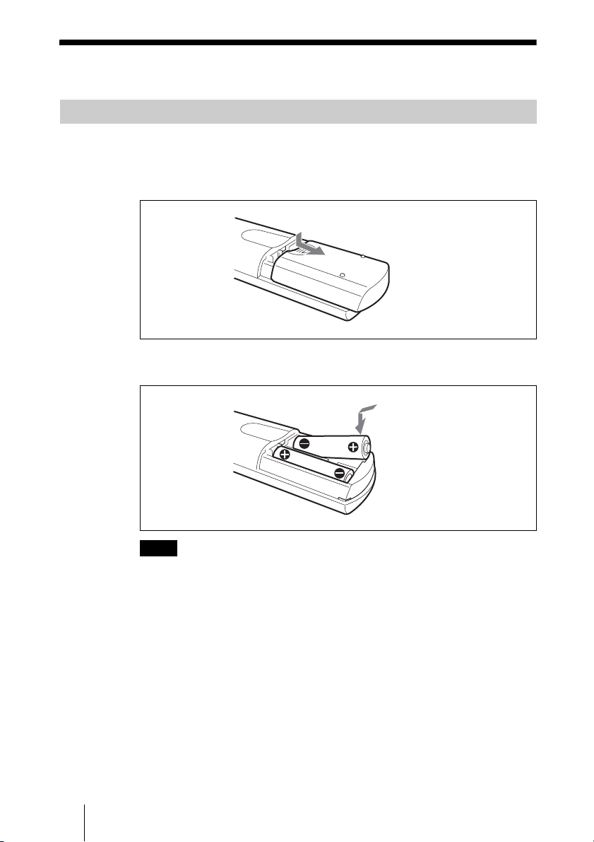
Inserting Batteries into the Remote Commander
Most of the operations with the Video Communication System can be
controlled with the supplied Remote Commander.
1 Remove the battery compartment cover.
2 Insert two size AA (R6) batteries (supplied) with correct polarities into the
battery compartment.
Note
Be sure to insert the batteries E side first. Inserting them forcibly e side first may
damage the insulated film covering the batteries and cause a short circuit.
3 Replace the cover.
Battery life
When the Remote Commander does not function properly, replace both the
batteries with new ones.
Notes on batteries
To avoid damage from possible battery leakage or corrosion, observe the
following:
• Make sure to insert the batteries with the polarities in the correct direction.
• Do not mix old and new batteries, or different types of batteries.
• Do not attempt to charge the batteries.
12 Preparing the System
Page 13

• If you do not intend to use the Remote Commander for a long period of time,
remove the batteries.
• If battery leakage occurs, clean the battery compartment and replace all the
batteries with new ones.
Turning On/Off the TV Monitor Together With the Communication
Terminal
If you use a Sony TV, insert the IR repeater under the remote sensor of the TV.
Once you set the IR repeater, the TV will turn on or go to standby together with
the Communication Terminal when you press the
Remote Commander.
CAMERA UNIT MIC
IR OUT
12
to IR OUT
100BASE-TX
10BASE-T
(PLUG IN POWER)
12
DSB
ISDN UNIT WHITE
DC 19.5V
BOARD
"/1 button on the supplied
TV monitor
Remote sensor
IR repeater (supplied)
Chapter 1: Installation and Preparation
Note
If the TV monitor is not turned on by pressing the @/1 button on the Remote
Commander, change the “IR Repeater Mode” setting in the General Setup menu.
For details on the “IR Repeater Mode” setting, see “General Setup Menu” on
page 24.
13Preparing the System
Page 14
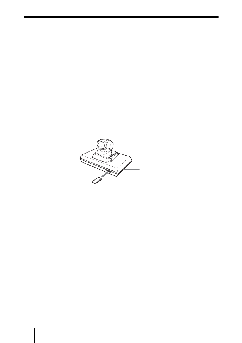
Installing the SCCP Software
Notes on installing the SCCP software
• You cannot install the software if the write-protect tab on the “Memory
Stick” in which the SCCP software is stored is set to “LOCK”.
• Once the SCCP software is installed in the Video Communication System,
the software will not be used again.
• You cannot install the SCCP software which is copied to another “Memory
Stick” with a computer, etc.
1 Set the power switch on the right side of the Communication Terminal to
the off position (
2 Insert the “Memory Stick” containing the PCSA-SC1 SCCP software into
the Memory Stick slot.
Insert the “Memory Stick” in the direction of the arrow with the mark facing
upward.
a).
Power switch
PCSA-SC1 SCCP software
3 Set the power switch on the right side of the Communication Terminal to
the on position (
The SCCP software is installed in the Communication Terminal.
14 Installing the SCCP Software
@).
Page 15

Turning the System On/Off
This section describes how to turn on or off the Communication Terminal.
Turning On
Before using the system, make sure that the system connections have been
completed correctly and the SCCP software has been installed.
For connecting the system, see “System Connections” on page 11.
For installation of the SCCP software, see “Installing the SCCP Software” on
page 14.
1 Turn on the TV monitor.
If the IR repeater is installed in the Sony TV monitor, set the TV monitor to
standby mode. The TV monitor will turn on simultaneously when the
Communication Terminal is turned on.
2 Turn on the power of any other equipment to be used for the
videoconference.
3 Set the power switch on the right side of the Communication Terminal to
the on position (
The Communication Terminal turns on.
@).
Chapter 1: Installation and Preparation
POWER indicators
(Light in green.)
Three indicators on the front of the Communication Terminal and the POWER
indicator on the camera light, then only the POWER indicators on both units
remain on in green. The launcher menu will appear on the monitor screen and
the picture shot by the local camera will also appear in the launcher menu.
Power switch
15Turning the System On/Off
Page 16

Launcher menu
22:56 10/12/2005
2001
Menu
INFORMATION
2
NewCall
3
CFwdAll
1
Redial
Notes
• After the power is turned on, the camera moves automatically for trial operation. Be
careful not to catch your finger.
• If you use force to prevent the camera moving, it may not resume moving and not
output a signal to the Communication Terminal. In this case, turn off the Terminal,
and turn it on again.
Standby Mode Function
To save power, the Communication Terminal will enter standby mode if you
do not operate it for a specified period of time.
When the Communication Terminal is in standby mode, the POWER indicator
lights in orange. Once the Communication Terminal receives a call, the
standby mode is automatically released.
To release the standby mode
Press the
@/1 button on the Remote Commander.
12345678
12345678
12345678
ABCDEFGH
ABCDEFGH
ABCDEFGH
456
To specify the standby time
Specify the time that you want the system to remain on before entering into
standby mode (1 to 99 minutes) using “Standby Time” in the General Setup
menu. If you do not want the system to enter the standby mode, set “Standby
Mode” in the General Setup menu to “Off”.
For the “Standby Time” and “Standby Mode” settings, see “General Setup
Menu” on page 24.
Notes
• The POWER indicator on the camera goes off when the system enters standby mode.
• If you use a Sony TV monitor with the IR repeater installed under the remote sensor,
the TV monitor will enter standby mode together with the Communication Terminal.
16 Turning the System On/Off
Page 17

Setting the Video Communication System to Standby Mode
You can turn on the Video Communication System with the @/1 button on the
Remote Commander if it is in standby mode.
1 Display the launcher menu on the monitor screen, then press the @/1 button
on the Remote Commander.
The message “Power off?” appears on the monitor screen.
2 Press the B or b button on the Remote Commander to select “OK”, and
press the PUSH ENTER button.
You may press the @/1 button on the Remote Commander.
POWER indicator (Not lit.)
POWER indicator (Lights in orange.)
@/1 button
B/b buttons and PUSH ENTER
button
The Video Communication System enters standby mode and the POWER
indicator on the Communication Terminal lights in orange. The POWER
indicator on the camera goes out.
If the IR repeater is installed in a Sony TV monitor, it will go into standby
together with the Video Communication System.
Chapter 1: Installation and Preparation
Note
When the Communication Terminal and the Camera are separately installed, point the
Remote Commander to the Camera for operations.
To cancel setting the system to standby
Select “Cancel” with the B or b button on the Remote Commander, then press
the PUSH ENTER button in step 2 above.
17Turning the System On/Off
Page 18
Turning Off
1 Set the power switch on the right side of the Communication Terminal to
the off position (
a).
2 Turn off the power of other equipment used for the videoconference.
Note
Set the power switch on the Communication Terminal off when the system will not be
used for an extended period. While the power switch is off, you cannot receive a call
from a remote party.
Adjusting the Volume on the TV Monitor
Before adjusting the volume on the TV monitor, set the volume on the
Communication Terminal to the appropriate position.
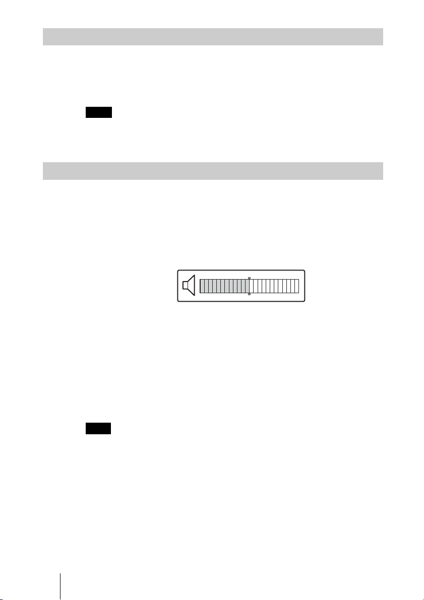
1 Press the VOLUME +/– buttons on the Remote Commander to set the
volume level on the adjustment bar displayed on the screen to the middle
position.
2 Adjust the volume on the TV monitor so that you can properly hear a
remote party speaking.
To adjust the picture on the TV monitor
Use the controls on the TV monitor to adjust the picture, hue, contrast,
brightness or sharpness.
For details on picture adjustments, refer to the Operating Instructions of the
TV.
Note
Do not activate the TV’s surround sound feature as it cause strange sound since the echo
canceler of the Communication Terminal does not function properly.
18 Turning the System On/Off
Page 19

Displaying the Versions, etc.
You can check the version of the Communication Terminal, the host name and
IP address set for this system, etc. by displaying the Machine Information
menu on the monitor screen.
For details on the Machine Information menu, see “Machine Information
Menu” on page 30.
Chapter 1: Installation and Preparation
19Turning the System On/Off
Page 20
Using the Menu
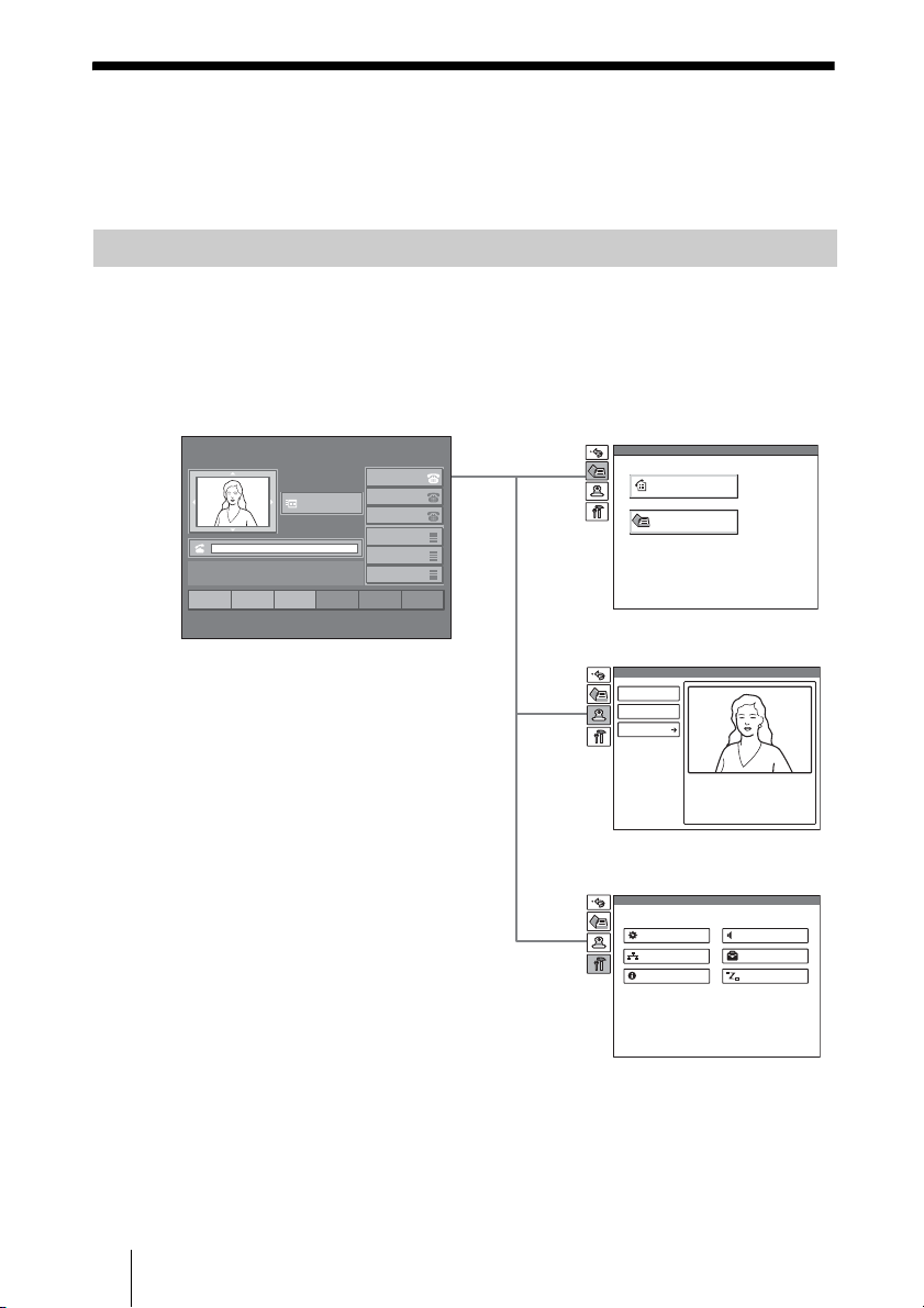
The Video Communication System uses the on-screen menus to make various
adjustments and settings. This section gives a brief introduction of the menus.
Menu Configurations
The menus of this system configure as described below.
For more detailed menu configurations, refer to “Menu Configuration” on
page 101.
Launcher menu
2
NewCall
3
1
Redial
22:56 10/12/2005
2001
Menu
INFORMATION
456
CFwdAll
12345678
12345678
12345678
ABCDEFGH
ABCDEFGH
ABCDEFGH
Phone Book menu
Phone Book
History
Corporate Directory
Camera menu
Camera
Preset Save
Preset Load
Adjustments
Setup menu
Setup
General
LAN
Information
Audio
Administrator
Status
20 Using the Menu
Page 21

Menu Icons
Selecting the icons on the menu tabs shown
on the left side of the menu displays each
menu.
Icon Displayed menu
Returns to the previous menu.
Phone Book menu
Camera menu
The Setup menu for the administrator is used
to set various items on the system.
The menu appears when you press the
MENU button on the Remote Commander
or select “Menu” in the launcher menu.
For details on the Setup menu, see pages 23
to 31.
Phone Book menu
Phone Book
History
Chapter 1: Installation and Preparation
Setup menu
Introduction of Menus
Launcher menu
22:56 10/12/2005
2001
Menu
INFORMATION
2
NewCall
3
456
CFwdAll
1
Redial
The launcher menu appears when the Video
Communication System is turned on or is
displayed while it is not connected to a
remote party.
For details on the launcher menu, see pages
33 to 34.
Setup menu
Setup
General
LAN
Information
12345678
12345678
12345678
ABCDEFGH
ABCDEFGH
ABCDEFGH
Audio
Administrator
Status
Corporate Directory
The Phone Book menu is used to display the
call history or search the corporate directory
registered in the SCCP server.
The menu appears when you press the
MENU button on the Remote Commander
to display the Setup menu and select
from the menu tabs displayed.
For details on the Phone Book menu, see
pages 37 to 40.
Camera Menu
Camera
Preset Save
Preset Load
Adjustments
The Camera menu is used to adjust camera
angle or zooming of the displayed image.
The menu appears when you press the
MENU button on the Remote Commander
to display the Setup menu and select
from the menu tabs displayed.
For details on the Camera menu, see pages
60 to 65.
21Using the Menu
Page 22

Entering Characters
desired symbol. Pressing the 0 button also
enables you to enter the symbol.
This section explains how to enter the
letters, numerals or symbols on the text box
in the menu using the Remote Commander.
MIC
ON/OFF
VOLUME
ZOOM
VIDEOINPUT
DISPLAY
SELECT
CLEAR SYMBOL
PinP FAR/NEAR
BACK
ALPHA/
SPACE
NUM
PUSH
ENTER
RETURN MENU
CONNECT/
DISCONNECT
HELP
DISPLAY
(CLEAR) button
VIDEO INPUT
SELECT
(SYMBOL)
button
FAR/NEAR
(ALPHA/NUM)
button
PinP (BACK
SPACE)
button
Number buttons
(dot) button
To enter a dot (.) for an IP address
Press the button.
To delete a character
Press the PinP (BACK SPACE) button. The
last entered character is deleted.
To delete all characters in a line
Select the line to be deleted, then press the
DISPLAY (CLEAR) button.
PCS-R1
To enter letters or numerals
1 Press the FAR/NEAR (ALPHA/
NUM) button repeatedly to enable the
alphabet or numerals to be input.
2 Press the number buttons repeatedly to
enter the letters or numerals you want.
You can enter the letter shown on each
button by pressing it repeatedly.
You can enter the numeral shown on
each button by pressing it.
To enter a symbol
Press the VIDEO INPUT SELECT
(SYMBOL) button repeatedly to select the
22 Using the Menu
Page 23

Chapter 2:
Registration and
Setup for System
Administrators
This chapter describes the registration and
settings to be carried out by the system
administrator.The chapter is intended to be
read by the system administrator.
Registering Local
Information
Before starting a conference, register the
required information on the local terminals
of the system using the Setup menu. This
section describes how to display the Setup
menus and gives a introduction to the
menus.
Opening the Setup Menu
1 Press the MENU button on the
Remote Commander or use the V, v,
B or b button to select “Menu” in the
launcher menu, then press the PUSH
ENTER button.
The Setup menu appears on the monitor
screen.
Setup
General
LAN
Information
Choosing the following items from the
Setup menu opens the respective menus.
Audio
Administrator
Status
General: General Setup menu (see page
24)
Audio: Audio Setup menu (see page 26)
LAN: LAN Setup menu (see page 27)
Administrator: Administrator Setup
menu (see page 29)
Information: Machine Information
menu (see page 30)
Status: Status menu (see page 30)
2 Use the V, v, B or b button on the
Remote Commander to select the
menu you want to set, then press the
PUSH ENTER button.
The selected setup menu appears.
General Setup
Page: 1/3
Terminal Name
Dual Monitor
Monitor Out
Standby Mode
Standby Time
Time Display
PCS-1
ISDN
Off
VIDEO OUT
On
30 minutes
On
Save Cancel
3 Set the respective items.
For details on individual items, see the
relevant menu pages.
4 After the setting is completed, use the
V, v, B or b button to select “Save”,
then press the PUSH ENTER button.
The setting is saved, and the Setup menu
is restored.
To cancel the setup
Use the V, v, B or b button on the Remote
Commander to select “Cancel”, then press
the PUSH ENTER button. Or press the
RETURN button on the Remote
Commander.
To page up or down the selected
menu
V, v, B or b button on the Remote
Use the
Commander to select the Page box, then
press the
the
b button to advance the page and
B button to go back to the previous page.
Chapter 2: Registration and Setup for System Administrators
23Registering Local Information
Page 24
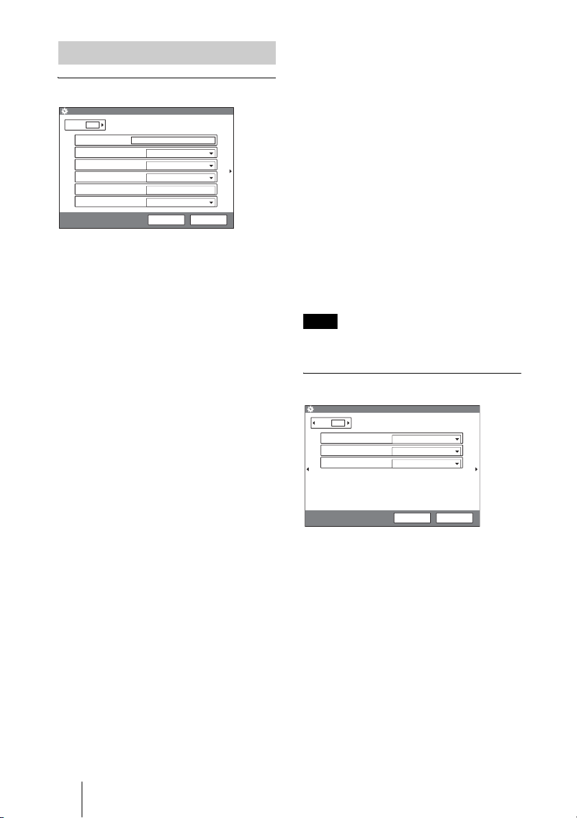
General Setup Menu
Page 1/3
General Setup
Page: 1 /3
Terminal Name
Dual Monitor
Monitor Out
Standby Mode
Standby Time
Time Display
PCS-1
ISDN
Off
VIDEO OUT
On
30 minutes
On
Save Cancel
Standby Mode
Sets whether the Communication Terminal
is set to standby mode if it is not operated for
a specified period of time.
On: Activates standby mode.
Off: Deactivates standby mode.
Standby Time
Specifies the time that the system remains on
before entering the standby mode. You can
specify a time between 1 and 99 minutes.
For details on standby mode, see “Standby
Mode Function” on page 16.
Terminal Name
Input the name of this system.
Dual Monitor
When two monitors are connected to the
System, selects whether you use the dual
monitor mode.
On: Enables the dual monitor mode. Still
images are always displayed on the
second monitor.
Off: Disables the dual monitor mode. Still
images are always displayed on the first
monitor.
For details on the dual monitor mode, see
“Using Two Monitors – Dual Monitor” on
page 69.
Monitor Out (or Sub Monitor Out)
Selects the output connected to the monitor
to which the signal is output.
This item changes to “Sub Monitor Out” if
“Dual Monitor” is set to “On”, and selects
the output connected to the sub-monitor
(second monitor) to which the signal is
output.
RGB OUT: Outputs from the RGB OUT
connector on the Communication
Terminal.
VIDEO OUT: Outputs from the VIDEO
OUT MONITOR MAIN or SUB
connector.
For details, see “Outputting Video Signals
to External Equipment” on page 79.
Time Display
Selects whether you display the elapsed time
on the monitor screen during the conference.
On: Displays the elapsed time.
Off: Does not display the elapsed time.
Note
During communication, some items are not
displayed.
Page 2/3
General Setup
Page: 2 /3
Language
IR Repeater Mode
Character Input Help
English
MODE1
On
Save Cancel
Language
Selects the language used for messages or
menus.
You can select English or Japanese.
IR Repeater Mode
Selects the remote control mode of the IR
repeater.
MODE 1: (For customers who are using the
PCS-1 Video Communication System
only)
Normally, select this mode.
MODE 2: (For customers who are using the
PCS-1 Video Communication System
only)
24 Registering Local Information
Page 25
Select this mode if the system does not
operate properly with the MODE 1
setting.
MODE 3: (For customers who are using the
PCS-1P Video Communication System
only)
Normally, select this mode.
MODE 4: (For customers who are using the
PCS-1P Video Communication System
only)
Select this mode if the System does not
operate properly with the MODE 3
setting.
Character Input Help
Selects whether or not to hide a help balloon
used for entering characters or numerics .
On: Displays the balloon help items for
entering characters.
Off: Hide the balloon help items for entering
characters.
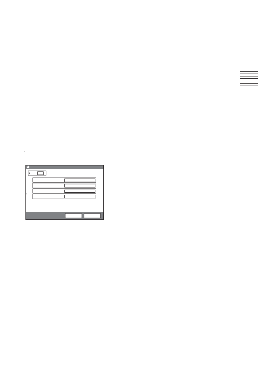
Page 3/3
General Setup
Page: 3/3
Main
Object
AUX1
AUX2
Custom Input Label
Terminal) is selected in the Video Input
Select menu.
AUX2
Enter the label to be displayed when
“AUX2” (equipment connected to the
VIDEO IN AUX2 on the Communication
Terminal) is selected in the Video Input
Select menu.
Chapter 2: Registration and Setup for System Administrators
Save Cancel
You can label each video input displayed in
the Video Input Select menu (page 66) on
the local site.
Main
Enter the label to be displayed when “Main”
(main camera) is selected in the Video Input
Select menu.
Object
Enter the label to be displayed when
“Object” (optional PCS-DS150/DS150P
Document Stand) is selected in the Video
Input Select menu.
AUX1
Enter the label to be displayed when
“AUX1” (equipment connected to the
VIDEO IN AUX1 on the Communication
25Registering Local Information
Page 26

Audio Setup Menu
The Audio Setup menu is used to set various
audio items.
Page 1/3
The level meter indicating the audio input
level is displayed.
Audio Setup
Page: 1/3
Input Select
Selects the sound to be input.
MIC: Inputs the sound of the microphone.
AUX: Inputs the sound from external
MIC+AUX: Inputs both sounds from the
Mic Select
Selects the microphone to be used.
Internal: Uses the built-in microphone.
External: Uses the microphone connected
CTE
Selects the input to which the CTE-600
Communication Transducer is connected.
Off: Does not use the CTE-600
AUX: Inputs from the AUDIO IN jack on
Echo Canceler
Selects whether you use the echo canceler.
Internal: Enables the built-in echo canceler.
External: Uses the echo canceler of the
Off: Disables the built-in echo canceler.
Input Select
Mic Select
CTE
Echo Canceler
Lip Sync
Recording Mute
MIC
Internal
Off
Internal
Off
On
Save Cancel
equipment.
microphone and external equipment.
to the Communication Terminal.
Communication Transducer.
the Communication Terminal.
external equipment connected.
The input from the AUDIO IN jack on
the Communication Terminal is always
available regardless of the “Input
Select” setting.
Lip Sync
Selects whether to enable the Lip Sync
function.
On: Enables the Lip Sync function. The
movement of the speaker’s lips is
synchronized with his voice.
Off: Disables the Lip Sync function.
Recording Mute
When connecting a video cassette recorder
to the AUDIO IN/AUDIO OUT (MIXED)
jacks to record the sound for a conference,
the recording mute function prevents echo
from reflecting on a remote site. This item is
only available when “Input Select” is set to
“AUX” or “MIC + AUX”.
On: Enables the recording mute function.
Off: Disables the recording mute function.
Page 2/3
Audio Setup
Page: 2 /3
Beep Sound
Sound Effect
Dial Tone
Ringer Tone
On
On
On
On
Save Cancel
Beep Sound
Selects whether the beep sounds when you
press the button on the Remote Commander.
On: Enables beep.
Off: Disables beep.
Sound Effect
Selects whether or not to output the sound
when the system starts up, a
videoconference starts, or the
videoconference ends.
On: Outputs the sound.
Off: Does not output the sound.
Dial Tone
Selects whether or not to output a ring-back
tone and busy tone when you are dialing.
On: Outputs the dial tone.
Off: Does not output the dial tone.
26 Registering Local Information
Page 27

Ringer Tone
Selects whether or not to output a ringer tone
when you receive a call.
On: Outputs the ringer tone.
Off: Does not output the ringer tone.
Page 3/3
Audio Setup
Page: 3 /3
Line 1 Ringer
Line 2 Ringer
Line 3 Ringer
Ringer 1
Ringer 1
Ringer 1
LAN Setup Menu
The LAN Setup Menu is used to set LAN
items.
For details on the settings, consult with the
network administrator.
Note
When you change the setting of any item in
the LAN Setup menu on page 1/4, 2/4 or 4/
4, the system will reboot automatically.
Page 1/4
Chapter 2: Registration and Setup for System Administrators
Save Cancel
Line 1 Ringer
Selects a ringer tone when you receive a call
via telephone line 1 from among “Ringer 1”,
“Ringer 2” or “Ringer 3”.
Select “Off” not to sound the ringer tone.
Line 2 Ringer
Selects a ringer tone when you receive a call
via telephone line 2 from among “Ringer 1”,
“Ringer 2” or “Ringer 3”.
Select “Off” not to sound the ringer tone.
Line 3 Ringer
Selects a ringer tone when you receive a call
via telephone line 3 from among “Ringer 1”,
“Ringer 2” or “Ringer 3”.
Select “Off” not to sound the ringer tone.
LAN Setup
Page: 1 /4
DHCP Mode
Host Name
IP Address
Network Mask
Gateway Address
DNS Address
Off
Auto
Auto
Auto
Auto
Auto
Save Cancel
DHCP Mode
Selects whether DHCP (Dynamic Host
Configuration Protocol) server is enabled or
not.
Auto: The IP address, network mask,
gateway address, and DNS address are
automatically assigned.
In this case, confirm the assigned IP
address in the Machine Information
menu after the LAN connection is
completed.
Off: Sets “DHCP Mode” to “Off”. In this
case, enter the IP address, network
mask, gateway address and DNS
address.
Host Name
Enter the host name.
IP address
Enter the IP address.
Network Mask
Enter the network mask.
Gateway Address
Enter the default gateway address.
27Registering Local Information
Page 28

DNS Address
Enter the DNS (Domain Name System)
address.
Page 2/4
Sets the items regarding the TFTP (Trivial
File Transfer Protocol) server.
Setting of this page is required when you set
“DHCP Mode” to “Off” on page 1/4 or when
your DHCP server does not have the
information on the TFTP server.
LAN Setup
Page: 2 /4
Alternate TFTP Server
TFTP Primary
TFTP Secondary
Off
. . .
Ringer 1
Ringer 1
. . .
Save Cancel
Alternate TFTP Server
Selects if you use a TFTP server.
On: Uses a TFTP server.
Off: Does not use a TFTP server.
TFTP Primary
Enter the address of the primary TFTP
server.
TFTP Secondary
Enter the address of the secondary TFTP
server.
Page 3/4
Default: Uses the default port numbers,
2253 for the TCP port number and
49152 for the UDP port number.
TCP Port Number
When “Port Number Used” is set to
“Custom”, enter the TCP port number.
UDP Port Number
When “Port Number Used” is set to
“Custom”, enter the UDP port number.
For details on the port numbers used, see
“List of Port Numbers Used on the PCSASC1” on page 95.
Page 4/4
LAN Setup
Page: 4 /4
SNMP Mode
Trap Destination
Community
Description
Location
Contact
Off
Public
Videoconference Device
Save Cancel
SNMP Mode
Selects whether the SNMP (Simple Network
Management Protocol) agent service is
enabled or not.
On: Enables the SNMP agent service.
Off: Disables the SNMP agent service.
Trap Destination
Enter the address of the trap destination
SNMP manager.
LAN Setup
Page: 3 /4
Port Number Used
TCP Port Number
UDP Port Number
Default
2253
49152
Save Cancel
Port Number Used
Selects whether or not to fix the TCP port
number and UDP port number.
Custom: Uses the port numbers set by the
user.
28 Registering Local Information
Community
Enter the community name managed by the
SNMP manager. The default setting is
“public”. Normally, there is no need to
change.
Description
Enter the description of this terminal. The
default setting is “Videoconference Device”
and cannot be changed.
Location
Enter the location where this terminal is
installed.
Page 29
Contact
Enter information on the administrator of
this terminal.
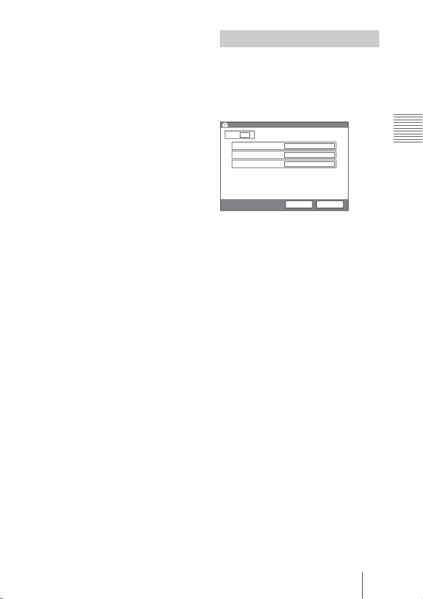
Administrator Setup Menu
The Administrator Setup menu is used for
the system administrators. If you have set
the password with this menu, you need to
enter it when accessing the setup menus to
change the items.
Administrator Setup
Page: 1 /1
Administrator Passward
Superuser Passward
Remote Access Passward
Web Monitor
Web Access
Administrator Password
Sets the password for the system
administrator.
The items in the Setup menu for the
administrator can be changed by the
administrator.
Superuser Password
Sets the password for the super-user.
(This item is not used for the current version
of the Video Communication System.)
On
Enabled
Save Cancel
Chapter 2: Registration and Setup for System Administrators
Remote Access Password
Sets the password required to access this
System from a Web browser. Accessing
from a Web browser is also enabled by
entering the administrator or superuser
password.
(This item is not used for the current version
of the Video Communication System.)
29Registering Local Information
Page 30
Machine Information Menu
Status Menu
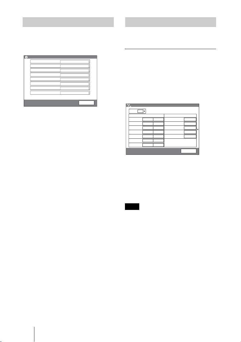
The Machine Information menu shows the
version of the Communication Terminal
host name, IP address, etc.
Machine Information
Host Version
DSP Version
Software Option
Option I/F
Host Name
IP Address
MAC Address
Serial Number
VerX.XX
VerX.XX
None
None
PCS-1
0.0.0.0
00-00-00-00-00-00
12345
End
Host Version
Displays the software version of the
Communication Terminal.
DSP Version
Displays the version of the built-in DSP
(Digital Signal Processor) for audio/video
codec.
Software Option
Displays the optional software installed.
(This item is not used for the current version
of the Video Communication System.)
Option I/F
Displays the optional connected equipment.
(This item is not used for the current version
of the Video Communication System.)
Host Name
Displays the host name.
IP Address
Displays the IP address.
MAC Address
Displays the MAC address.
Serial Number
Displays the serial number.
The Status menu shows the current status of
communication or LAN Connection Status.
Communication Status
The items below are shown both in the
columns for “Encode” and “Decode”. The
descriptions under “Encode” show the
setting status on the local system and those
under “Decode” show the status on
receiving.
Status
Page: 1 /2
Audio Mode
Video Mode
Frame Rate
Rate
MLP Rate
HMLP Rate
LSD Rate
Communication Status
(Encode) (Decode)
G.728
G.728
H.261CIF
H.261CIF
15fps
15fps
2 x 64k2 x 64k
OFF
OFF
OFF
OFF
6400 6400
Line I/F
Camera Control
Data Control
DSB
Whiteboard
Connection A
BRI
ON
ON
ON
OFF
Cancel
Audio Mode
Shows the current audio compression
format.
Video Mode
Shows the current video compression
format.
Note
The audio compression and video compression
formats used for communication with a remote
party may differ from the settings in this menu,
depending on the status of videoconferencing
system on the remote site.
Frame Rate
Shows the maximum frame rate of motion
pictures.
Rate
Displays the number of lines connected and
a transmission rate during communication.
30 Registering Local Information
Page 31
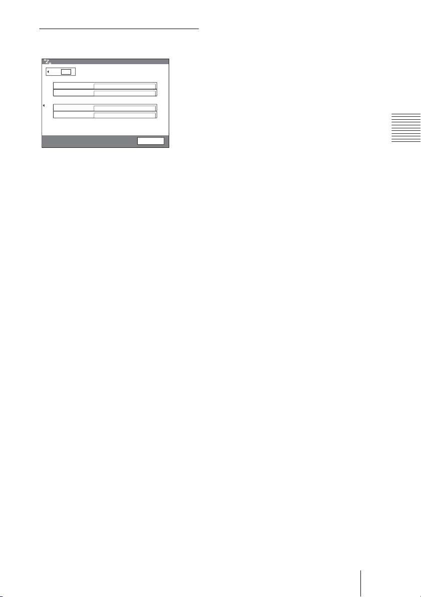
LAN Connection Status
Status
Page:
Audio Bit Rate
Video Bit Rate
Audio Data
Video Data
Camera Control Data
Packet Recovery Ratio
LAN Mode Speed : 100Mbps Duplex : Full
2/2
LAN Connection Status
Send Receive
97448 bps 96016 bps
1622620 bps 1627056 bps
Receive Packet Loss
0 / 7579 0 %
0 / 58085 0 %
0 / 2 0 %
/ %
End
Chapter 2: Registration and Setup for System Administrators
31Registering Local Information
Page 32
Chapter 3: Daily
Videoconference
This chapter describes how to conduct a videoconference from start to finish
after the administrator has completed various registrations and settings for the
system.
For use of optional equipment, see Chapter 4.
Starting a Conference by Calling a
Remote Party – NewCall
You can start a videoconference with a remote party by dialing. Once you have
made a connection to the remote party, you can begin talking just as with a
normal phone call and start a videoconference.
Turning on the Power
1 Turn on the TV monitor.
When the IR repeater is inserted under the remote sensor of the Sony TV, set
the TV to standby mode. When the power of the Communication Terminal is
turned on, the TV monitor will turn on simultaneously.
2 Turn on other equipment you are using for the videoconference.
3 Set the power switch on the right side of the Communication Terminal to
@).
on (
The Communication Terminal turns on.
POWER indicators (Lights in green.)
Three indicators on the front of the Communication Terminal and the POWER
indicator on the camera light, then only the POWER indicators on both units
32 Starting a Conference by Calling a Remote Party – NewCall
Power switch
Page 33
remain on in green. The launcher menu will appear on the monitor screen and
6
the picture shot by the local camera will also appear in the launcher menu.
Note
After the power is turned on, the camera moves automatically for trial operation. Be
careful not to catch your finger.
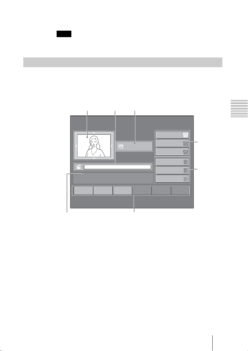
Using the Launcher Menu
The launcher menu appears on the monitor screen when the system is turned
on or while it is not connected to a remote party. The launcher menu displays
the image shot by the local camera, function keys, telephone line list, speed
dial list, etc.
1
Redial
NewCall
2
3
1
2
3
22:56 10/12/2005
2001
Menu
INFORMATION
456
CFwdAll
7
12345678
12345678
12345678
ABCDEFGH
ABCDEFGH
ABCDEFGH
1 Screen
The image shot by the local camera is displayed.
2 Text box
Enter the number of a remote party you want to call.
3 Menu button
To display the Setup menu, select this button by pressing the V, v, B or b
button and then the PUSH ENTER button on the Remote Commander.
Chapter 3: Daily Videoconference
4
5
4 Telephone line list
Displays available telephone lines.
You can select the line you want to use by pressing the V, v, B or b button and
then the PUSH ENTER button on the Remote Commander.
5 Speed dial list
Displays the speed dials.
33Starting a Conference by Calling a Remote Party – NewCall
Page 34

To dial the remote party registered on a speed dial, select the speed dial button
by pressing the V, v, B or b button and then the PUSH ENTER button on the
Remote Commander.
6 Message
A message to guide the operation appears here.
7 Function keys
Various functions can be assigned to the function keys. The assigned functions
depend on the call status or SCCP server being used.
To activate each function, select the function key by pressing the V, v, B or b
button and then the PUSH ENTER button on the Remote Commander.
Typical functions are as follows:
Indication on the function key Function
NewCall Dials a new remote party.
Redial Redials the remote party called last.
Answer Answers a call from a remote party.
Hold Puts the active call on hold.
EndCall Ends a call.
Transfer Transfers the current call to another party
Park Parks the current call using a park number on
Confrn Starts a conference by adding parties.
More Displays the next page if more options are
Resume Returns to the held call.
DirTrfr Transfers the current call to another party
Select Selects a held call when you use DirTrfr,
Join Allows held calls to join in the current
CFwdAll Transfers all calls from remote parties to the
PickUp Answers a call directed to another terminal in
GPickUp Answers a call directed to any terminal in the
MeetMe Starts a MeetMe conference or joins in it.
after they consent to accept it.
the SCCP server.
available.
directly without their consent.
Confrn, Join, etc.
conference.
entered number.
your group.
specified group.
34 Starting a Conference by Calling a Remote Party – NewCall
Page 35
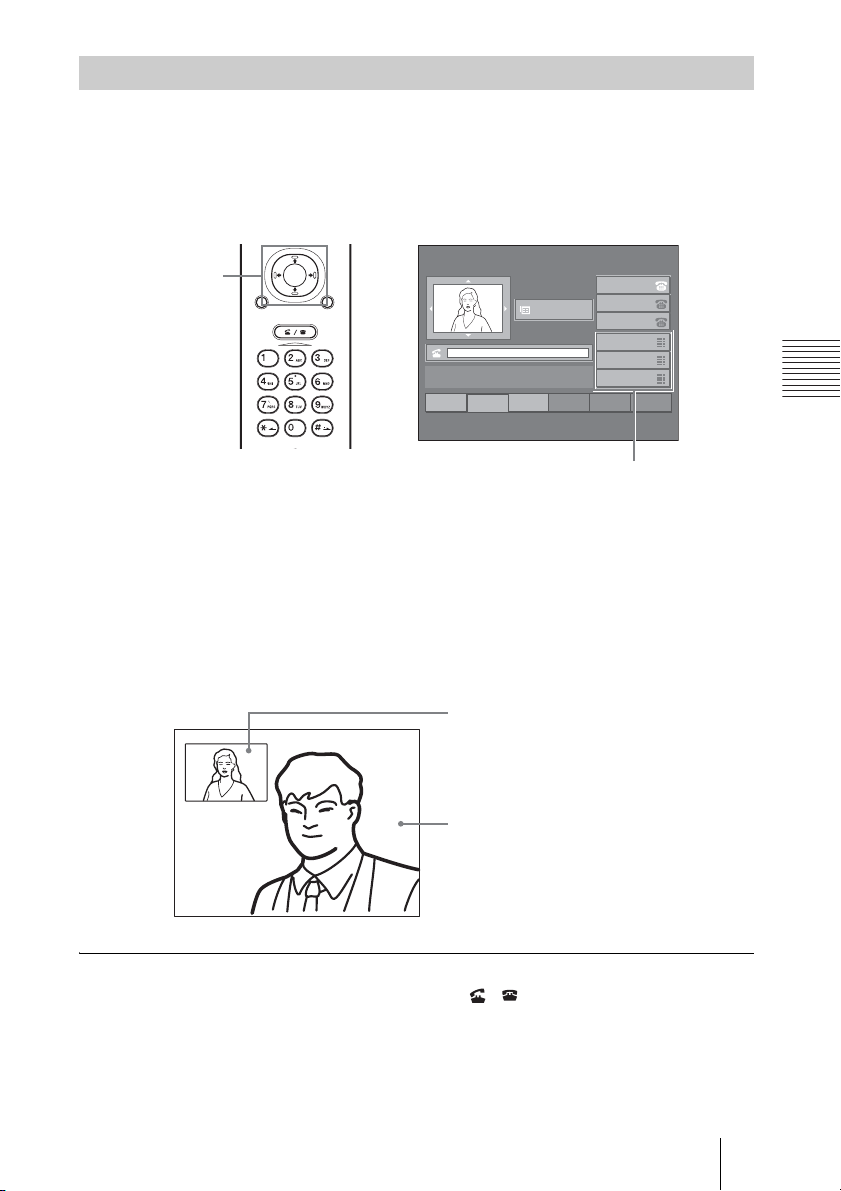
Calling a Remote Party Using Speed Dial
To call a remote party registered in the speed dial list, operate as follows.
The speed dials can be registered on the SCCP server. For details on
registration, consult the server administrator.
Launcher menu
V/v/B/b and
PUSH ENTER
buttons
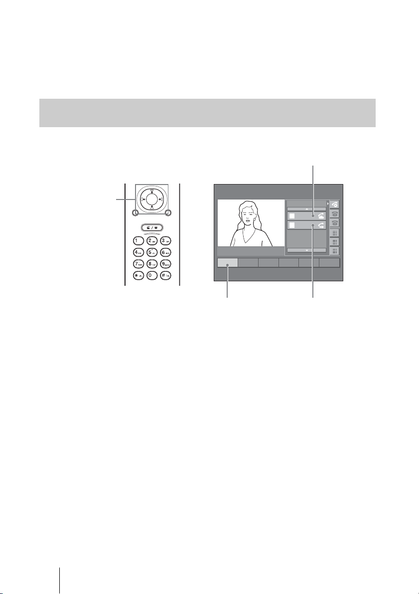
Select the speed dial button on which the remote party has been registered by
using the
ENTER button.
The system begins dialing the selected remote party.
When the system connects to the remote system, the picture of the remote site
appears on the monitor screen.
You can now start a videoconference.
PUSH
ENTER
RETURN MENU
CONNECT/
DISCONNECT
1
2
Redial
NewCall
HELP
V, v, B or b button on the Remote Commander. Then press the PUSH
22:56 10/12/2005
2001
Menu
INFORMATION
3
456
CFwdAll
12345678
12345678
12345678
ABCDEFGH
ABCDEFGH
ABCDEFGH
Chapter 3: Daily Videoconference
Speed dial list
Meeting starts!
To cancel dialing before connecting
Press the CONNECT/DISCONNECT ( / ) button on the Remote
Commander.
Picture of local site
Picture of remote site
35Starting a Conference by Calling a Remote Party – NewCall
Page 36
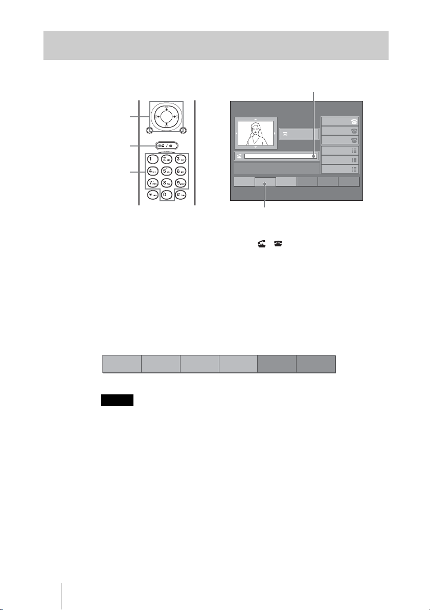
Calling a Remote Party by Entering a Number in the Launcher
Menu
Text box
22:56 10/12/2005
2001
Menu
INFORMATION
3
456
CFwdAll
12345678
12345678
12345678
ABCDEFGH
ABCDEFGH
ABCDEFGH
V/v/B/b and
PUSH ENTER
buttons
CONNECT/
DISCONNECT
button
Number buttons
PUSH
ENTER
RETURN MENU
CONNECT/
DISCONNECT
HELP
Launcher menu
1
2
Redial
NewCall
NewCall
1 Press the CONNECT/DISCONNECT ( / ) button on the Remote
Commander, or select “NewCall” using the V, v, B or b button and the
PUSH ENTER button.
2 Enter the number of the remote party using the number buttons on the
Remote Commander.
Presssing a number button allows you to enter a number in the text box.
When the first letter is input, the function key allocation changes as follows:
1
<<
2
Dial
AddrDial Cancel
4563
Notes
• To correct the entered number, select the function key assigned for “<<”. The last
entered number is deleted.
• To delete the entered number, press the function key assigned for “Cancel”.
• Do not enter the prefix number in the text box.
The system begins dialing the selected remote party.
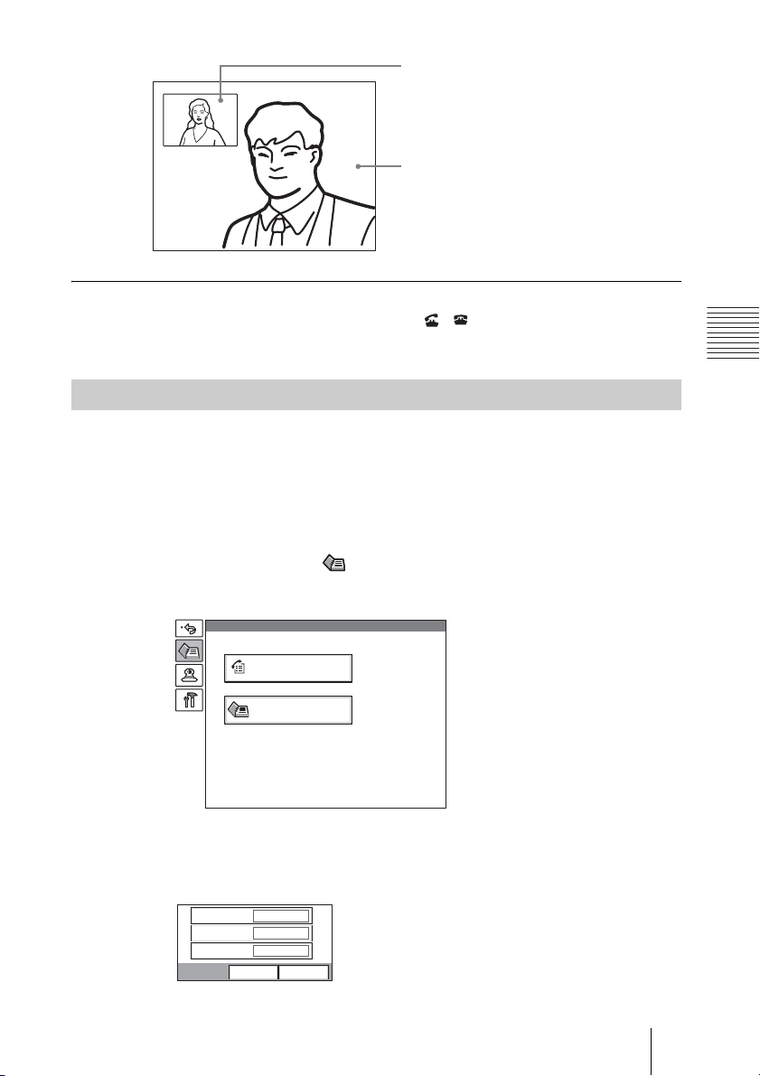
When the system connects to the remote system, the picture of the remote site
appears on the monitor screen.
You can now start a videoconference.
36 Starting a Conference by Calling a Remote Party – NewCall
Page 37
Picture of local site
Picture of remote site
Meeting starts!
To cancel dialing before connecting
Press the CONNECT/DISCONNECT ( / ) button on the Remote
Commander.
Calling a Remote Party Registered in the Phone Book
To call a remote party registered in the Phone Book of the SCCP server,
operate as follows:
The Phone Book can be registered on the SCCP server. For details on
registration, consult the server administrator.
1 Press the MENU button on the Remote Commander to display the Setup
menu, and select the (Phone Book) icon.
The Phone Book menu appears on the monitor screen.
Chapter 3: Daily Videoconference
Phone Book
History
Corporate Directory
2 Use the V, v, B or b button on the Remote Commander to select “Corporate
Directory”, then press the PUSH ENTER button.
The submenu for directory search appears on the monitor screen.
First Name
Last Name
Number
Search
Cancel
37Starting a Conference by Calling a Remote Party – NewCall
Page 38
3 Search for the remote party you want to call.
Select “First Name”, “Last Name” or “Number” box, and enter one or more
letters. Then select “Search”.
The searched result appears on the monitor screen.
If you select “Search” without entering any letter, the whole directory is
displayed.
Corporate Directory
Bill Adams 1234
Bill Brown
Bill Ford
Bill Smith
Bob Tailor
Bob William
4321
2521
5432
6789
2234
Cancel
4 Use the V or v button on the Remote Commander to select the remote
party, then press the PUSH ENTER button twice.
The system begins dialing the selected party.
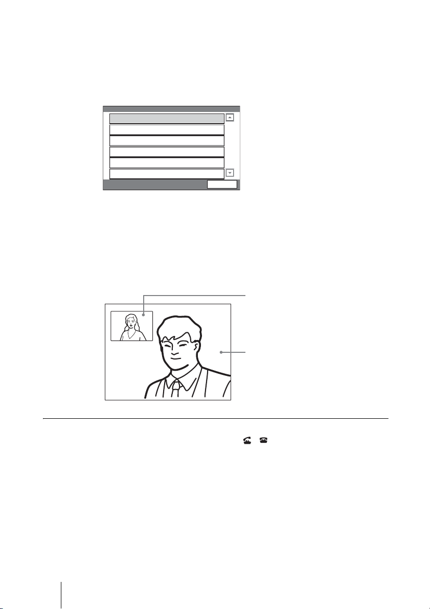
When the system connects to the remote system, the picture of the remote site
appears on the monitor screen.
You can now start a videoconference.
Picture of local site
Picture of remote site
Meeting starts!
To cancel dialing before connecting
Press the CONNECT/DISCONNECT ( / ) button on the Remote
Commander.
38 Starting a Conference by Calling a Remote Party – NewCall
Page 39
Calling a Remote Party Using the Call History
1 Press the MENU button on the Remote Commander to display the Setup
menu, and select the (Phone Book) icon.
The Phone Book menu appears on the monitor screen.
Phone Book
History
Corporate Directory
2 Use the V, v, B or b button on the Remote Commander to select “History”,
then press the PUSH ENTER button.
The History menu appears on the monitor screen.
History
1234 03/10/2005 18:00
4321
2521
5432
6789
2234
03/10/2005 17:45
03/10/2005 16:00
03/10/2005 09:35
03/09/2005 17:30
03/09/2005 15:40
Cancel
Chapter 3: Daily Videoconference
3 Use the V or v button on the Remote Commander to select the remote
party, then press the PUSH ENTER button twice.
The system begins dialing the selected party.
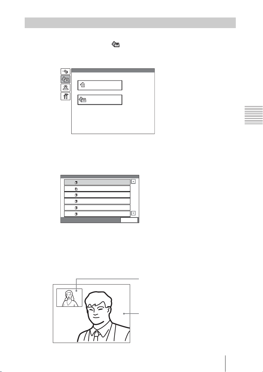
When the system connects to the remote system, the picture of the remote site
appears on the monitor screen.
You can now start a videoconference.
Picture of local site
Picture of remote site
Meeting starts!
39Starting a Conference by Calling a Remote Party – NewCall
Page 40
To cancel dialing before connecting
Press the CONNECT/DISCONNECT ( / ) button on the Remote
Commander.
Calling a Remote Party by Redialing
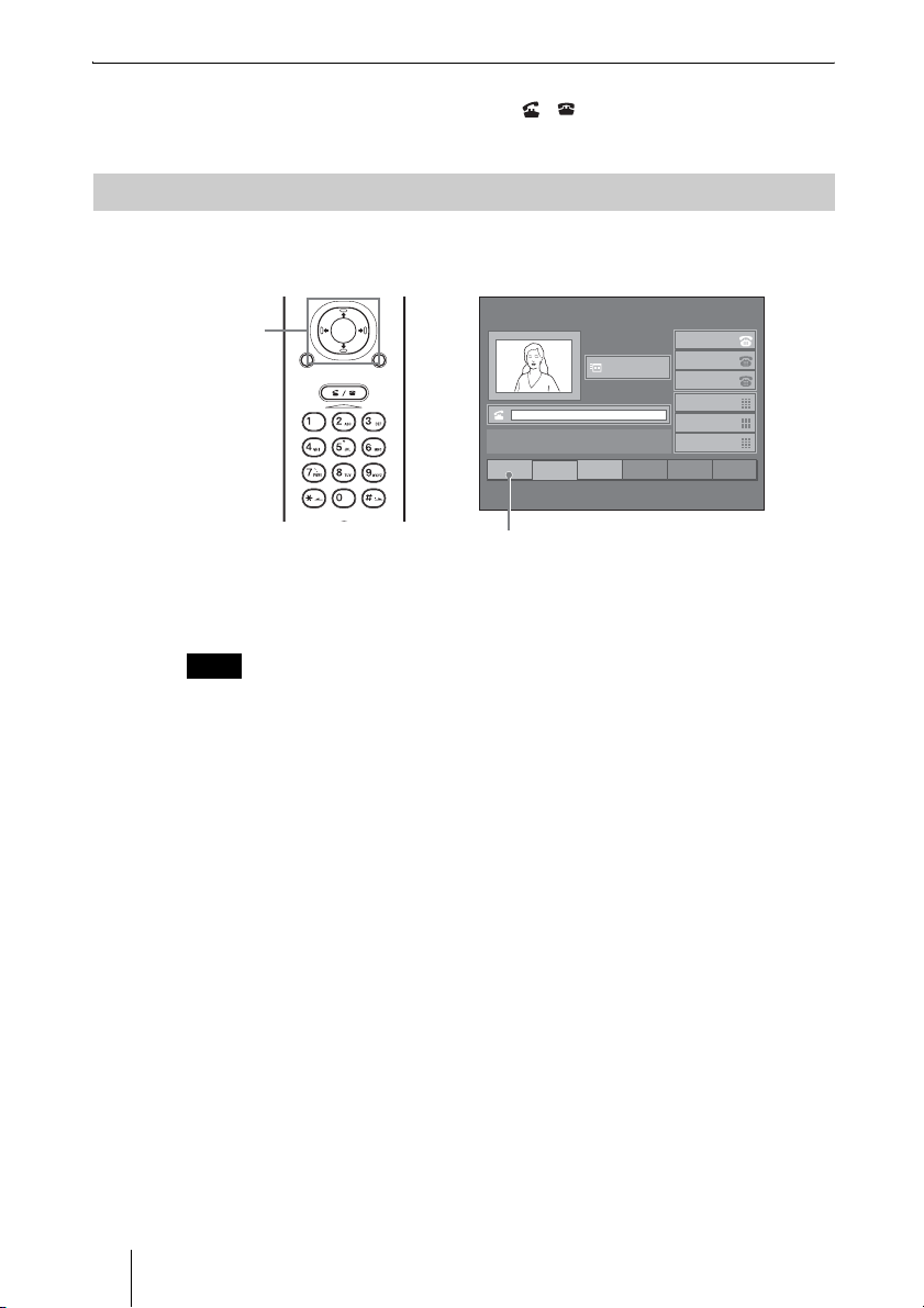
To call a remote party dialed last, operate as follows.
V/v/B/b and
PUSH ENTER
buttons
PUSH
ENTER
RETURN MENU
CONNECT/
DISCONNECT
HELP
22:56 10/12/2005
2001
Menu
INFORMATION
2
NewCall
3
CFwdAll
1
Redial
12345678
12345678
12345678
ABCDEFGH
ABCDEFGH
ABCDEFGH
456
Redial
Select the function key assigned for “Redial” using the V, v, B or b button and
the PUSH ENTER button on the Remote Commander.
The system dials the remote party you called last.
Note
Redialing is impossible after you turned off the power of the system or set it to standby
mode.
40 Starting a Conference by Calling a Remote Party – NewCall
Page 41
Receiving a Call from a Remote Party –
Answer
Call incoming display
V/v/B/b and
PUSH ENTER
buttons
CONNECT/
DISCONNECT
button
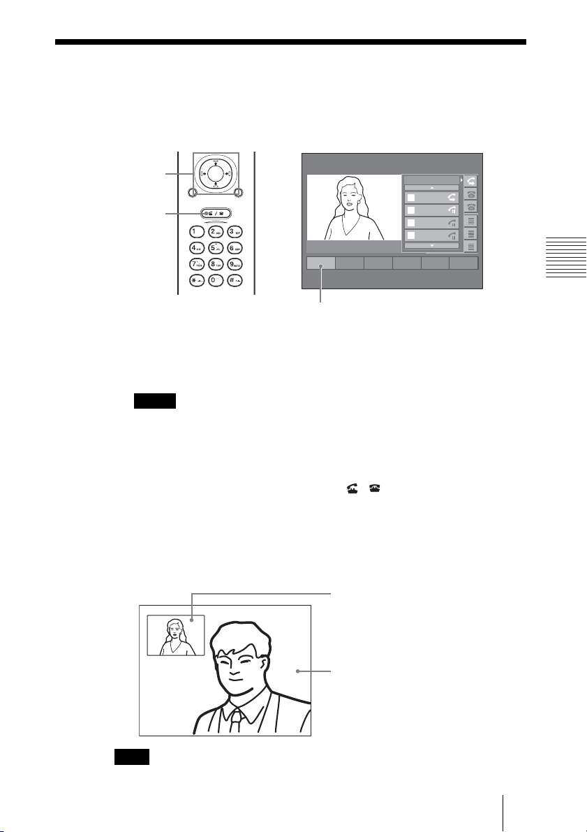
1 There is a call incoming from a remote party.
A ringer tone sounds on the Communication Terminal and the call incoming
display appears.
Notes
• You cannot answer the call unless the power switch on the Communication
Terminal is set to on (
• Make sure that the TV monitor is turned on. If you insert the IR repeater under
the remote sensor on the Sony TV, set the TV to standby mode.
PUSH
ENTER
RETURN MENU
CONNECT/
DISCONNECT
HELP
12345678
12345678
12345678
From
1
2345
12345678
From
2
6789
To
ABCDEFGH
3
ABCDEFGH
From
ABCDEFGH
4
ABCDEFGH
1
Answer
24563
ABCDEFGH
Answer
@).
Chapter 3: Daily Videoconference
2 Press the CONNECT/DISCONNECT ( / ) button on the Remote
Commander, or select “Answer” using the V, v, B or b button and the
PUSH ENTER button.
When the system connects to the remote system, the picture of the remote site
appears on the monitor screen.
You can now start a videoconference.
Picture of local site
Picture of remote site
Meeting starts!
Note
See pages 60 to 68 to adjust the sound and picture during the conference.
41Receiving a Call from a Remote Party – Answer
Page 42

To display an elapsed communication time
You can show an elapsed communication time on the monitor screen if “Time
Display” in the General Setup menu is set to “On”.
To turn the indicator off, set “Time Display” in the General Setup menu to
“Off”.
For “Time Display” setting, see “General Setup Menu” on page 24.
42 Receiving a Call from a Remote Party – Answer
Page 43
Putting a Call on Hold – Hold
Communication menu
V/v/B/b and
PUSH ENTER
buttons
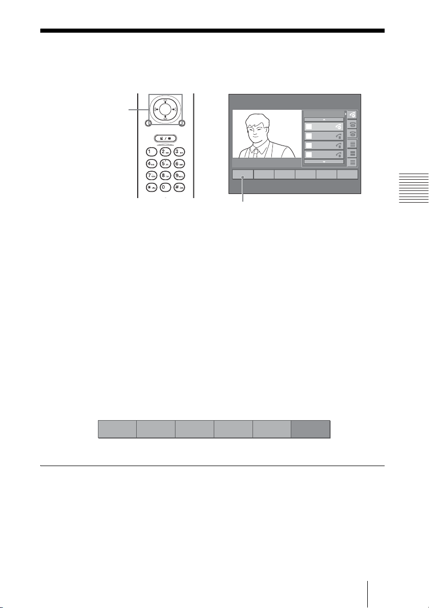
1 Press the PUSH ENTER button on the Remote Commander during
communication with a remote party.
The communication menu appears on the monitor screen.
2 Be sure to select the remote party whose call you want to put on hold.
3 Press the B or b button on the Remote Commander to select a function key.
4 Select “Hold” using the B or b button and the PUSH ENTER button on the
Remote Commander.
The picture of the remote site on the monitor screen changes to black and the
sound from the remote site is muted. The sound from the local site is no longer
sent to the remote site. (Hold mode)
PUSH
ENTER
RETURN MENU
CONNECT/
DISCONNECT
HELP
1
Hold
Hold
2
EndCall
3
Transfer
12345678
12345678
12345678
From
1
2345
12345678
From
2
6789
To
ABCDEFGH
3
ABCDEFGH
From
ABCDEFGH
4
ABCDEFGH
ABCDEFGH
4
Park5Confrn6More
Chapter 3: Daily Videoconference
The function key allocation changes as follows:
1
Resume2NewCall
To return to the held call
Select “Resume” using the V, v, B or b button and the PUSH ENTER button
on the Remote Commander.
The hold mode is cancelled and you can speak again to the remote party.
DirTrfr
4
Select
5
Join
63
43Putting a Call on Hold – Hold
Page 44
Ending the Conference – EndCall
To disconnect the line
Communication menu
V/v/B/b and
PUSH ENTER
buttons
CONNECT/
DISCONNECT
button
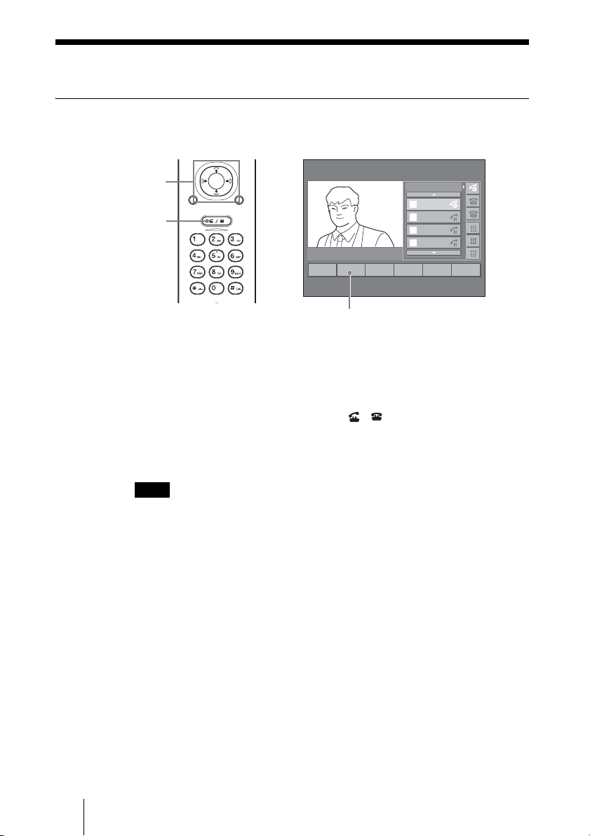
1 Press the PUSH ENTER button on the Remote Commander during
communication with a remote party.
The communication menu appears on the monitor screen.
2 Press the CONNECT/DISCONNECT ( / ) button, or select
“EndCall” using the V, v, B or b button and the PUSH ENTER button on
the Remote Commander.
The line is disconnected and the launcher menu is restored.
PUSH
ENTER
RETURN MENU
CONNECT/
DISCONNECT
HELP
1
Hold
2
EndCall
EndCall
3
Transfer
12345678
12345678
12345678
From
1
2345
12345678
From
2
6789
To
ABCDEFGH
3
ABCDEFGH
From
ABCDEFGH
4
ABCDEFGH
ABCDEFGH
4
Park5Confrn6More
Note
The power of the Communication Terminal remains on even if the line is
disconnected.
44 Ending the Conference – EndCall
Page 45
Calling or Answering Another Remote
Party During Communication
Calling Another Remote Party During Communication
Telephone line list
Communication menu
V/v/B/b and
PUSH ENTER
buttons
Number buttons
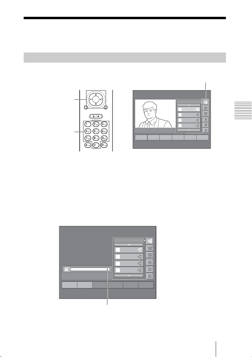
1 Press the PUSH ENTER button on the Remote Commander during
communication with a remote party.
The Communication menu appears on the monitor screen.
2 Select the telephone line you want to use for dialing from the telephone line
list, using the V, v, B or b button on the Remote Commander, then press
the PUSH ENTER button.
The remote party currently in communication enters hold mode, and a text box
appears on the monitor screen.
PUSH
ENTER
RETURN MENU
CONNECT/
DISCONNECT
HELP
12345678
12345678
12345678
From
1
2345
12345678
From
2
6789
To
ABCDEFGH
3
ABCDEFGH
From
ABCDEFGH
4
ABCDEFGH
2
EndCall
3
Transfer
1
Hold
ABCDEFGH
4
Park5Confrn6More
Chapter 3: Daily Videoconference
12345678
12345678
12345678
From
1
2345
12345678
From
2
6789
To
ABCDEFGH
3
ABCDEFGH
From
ABCDEFGH
4
ABCDEFGH
ABCDEFGH
1
Redial2Transfer
4563
Text box
3 Enter the number of your new remote party using the number buttons on
the Remote Commander.
45Calling or Answering Another Remote Party During Communication
Page 46
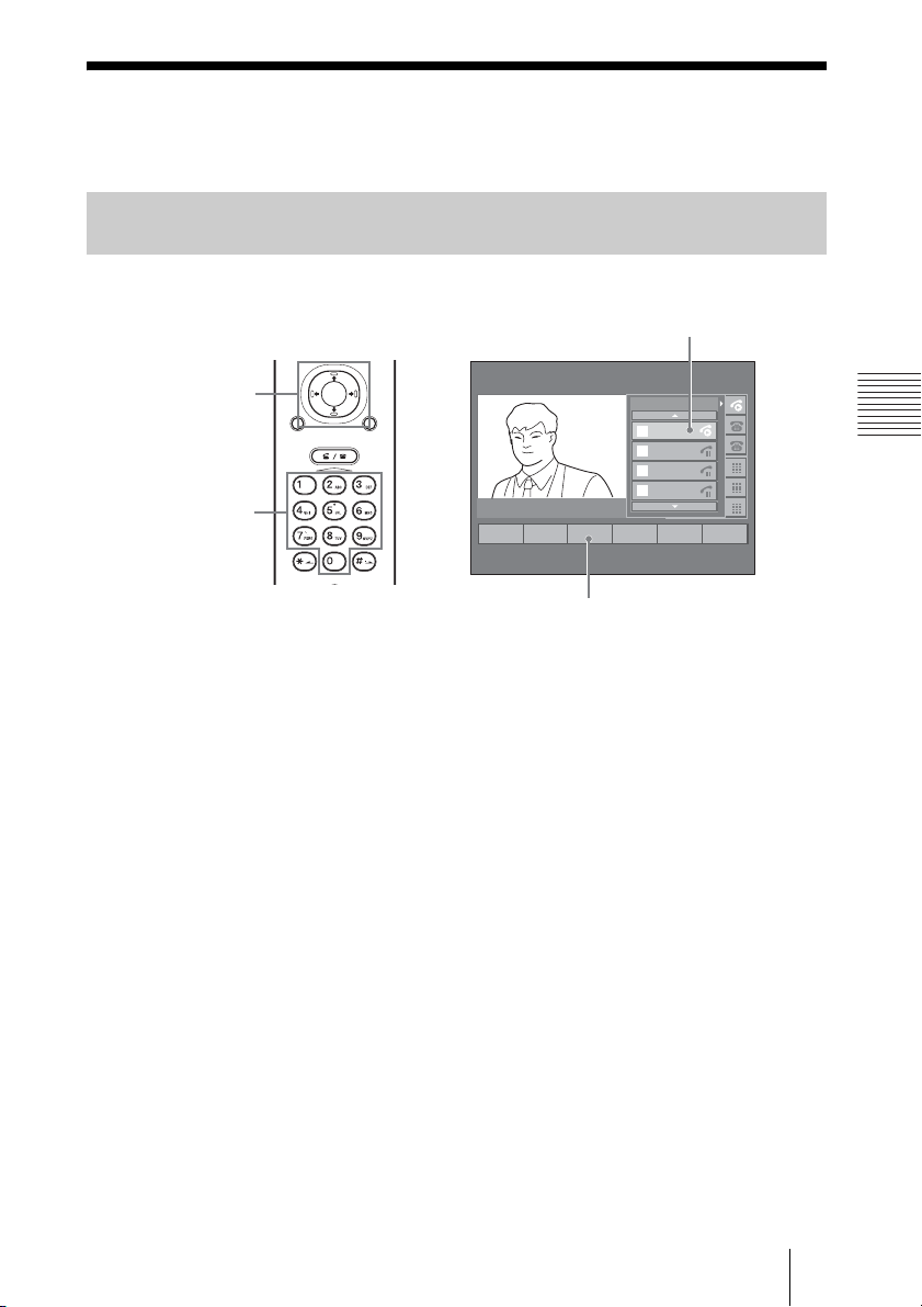
Pressing a number button allows you to enter a number in the text box.
The system begins dialing the selected remote party.
When the system connects to the remote system, the picture of the remote site
appears on the monitor screen.
You can now start a videoconference with the new remote party.
Answering a Call from Another Remote Party During
Communication
Call currently in
communication
Call incoming display
V/v/B/b and
PUSH ENTER
buttons
PUSH
ENTER
RETURN MENU
CONNECT/
DISCONNECT
HELP
1
Answer
24563
12345678
From
1
2345
From
2
6789
To
3
ABCDEFGH
From
4
ABCDEFGH
12345678
12345678
12345678
ABCDEFGH
ABCDEFGH
ABCDEFGH
Answer
1 There is an incoming call from a remote party during communication with
another remote party.
A ringer tone sounds on the Communication Terminal and the call incoming
display appears.
2 Select “Answer” using the V, v, B or b button and the PUSH ENTER
button on the Remote Commander.
The remote party currently in communication enters hold mode.
When the system connects to the new remote party, the picture of the remote
site appears on the monitor screen.
You can now start a videoconference with the new remote party.
46 Calling or Answering Another Remote Party During Communication
Newly incoming call
Page 47
Transferring a Call – Transfer/DirTrfr/
CFwdAll
Transferring a Call After Confirmation of the Destination Remote
Party – Transfer
Remote party to be
3
Transfer
transferred
12345678
12345678
12345678
From
1
2345
12345678
From
2
6789
To
ABCDEFGH
3
ABCDEFGH
From
ABCDEFGH
4
ABCDEFGH
ABCDEFGH
4
Park5Confrn6More
Communication menu
V/v/B/b and
PUSH ENTER
buttons
Number buttons
PUSH
ENTER
RETURN MENU
CONNECT/
DISCONNECT
HELP
2
1
EndCall
Hold
Transfer
1 Press the PUSH ENTER button on the Remote Commander during
communication with a remote party.
The communication menu appears on the monitor screen.
Chapter 3: Daily Videoconference
2 Select the icon of the remote party whose call you want to transfer to
another remote party using the V, v, B or b button on the Remote
Commander.
3 Press the B or b button on the Remote Commander to select a function key.
4 Select “Transfer” using the B or b button and the PUSH ENTER button on
the Remote Commander.
The remote party currently in communication enters hold mode, and a text box
appears on the monitor screen.
47Transferring a Call – Transfer/DirTrfr/CFwdAll
Page 48
12345678
12345678
12345678
From
1
2345
12345678
From
2
6789
To
ABCDEFGH
3
ABCDEFGH
From
ABCDEFGH
4
ABCDEFGH
ABCDEFGH
1
Redial2Transfer
4563
Text box
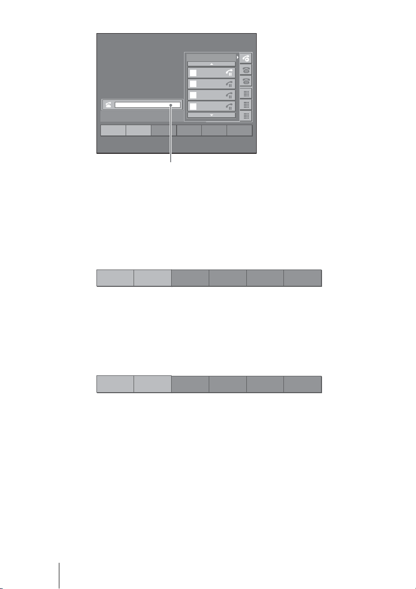
5 Enter the number of the remote party to whom you want to transfer the
current call in the text box using the number buttons on the Remote
Commander.
Presssing a number button allows you to enter a number in the text box.
When the first letter is input, the function key allocation changes as follows:
1
<<
2
EndCall
4563
The system begins dialing the remote party selected for transfer destination.
6 When the selected remote party answers, inform them that you are
transferring a call, and then select “Transfer” using the V, v, B or b button
and the PUSH ENTER button on the Remote Commander.
1
EndCall
Transfer of the call is now completed.
2
Transfer
4563
48 Transferring a Call – Transfer/DirTrfr/CFwdAll
Page 49
Transferring a Call Without Confirmation of the Destination
Remote Party – DirTrfr
Transfer destination
Communication menu
V/v/B/b and
PUSH ENTER
buttons
PUSH
ENTER
RETURN MENU
CONNECT/
DISCONNECT
12345678
12345678
12345678
From
1
2345
12345678
From
2
6789
To
ABCDEFGH
3
ABCDEFGH
From
ABCDEFGH
4
ABCDEFGH
2
EndCall
3
Transfer
1
Hold
ABCDEFGH
4
Park5Confrn6More
HELP
1 Press the PUSH ENTER button on the Remote Commander during
communication with a remote party.
The communication menu appears on the monitor screen.
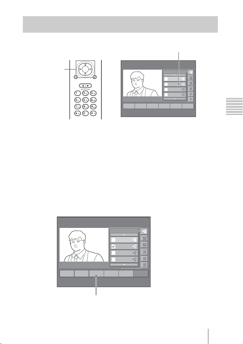
2 Select the icon of the remote party (in hold mode) to whom you want to
transfer the current call using the V, v, B or b button on the Remote
Commander.
3 Press the B or b button on the Remote Commander to select a function key.
4 Select “Select” using the B or b button and the PUSH ENTER button on
the Remote Commander.
A checkmark is displayed on the selected remote party.
12345678
12345678
12345678
From
1
2345
12345678
From
6789
To
ABCDEFGH
3
ABCDEFGH
From
ABCDEFGH
4
ABCDEFGH
ABCDEFGH
1
Resume
2
NewCall
3
DirTrfr
4
Select5Join
6
More
Chapter 3: Daily Videoconference
DirTrfr
5 Press the B or b button on the Remote Commander to select a function key.
49Transferring a Call – Transfer/DirTrfr/CFwdAll
Page 50
6 Select “DirTrfr” using the B or b button and the PUSH ENTER button on
the Remote Commander.
The call is transferred to the selected remote party.
Transferring All Incoming Calls – CFwdAll
You can automatically transfer all calls incoming through the same telephone
line to the specified destination.
Note
The “CFwdAll” feature allows you to transfer only calls incoming through the
telephone line listed first (displayed on the top of the telephone line list).
Calls incoming through the second and third telephone lines, if provided, cannot be
transferred.
To specify the destination for the “CFwdAll” feature
Text box
V/v/B/b and
PUSH ENTER
buttons
PUSH
ENTER
RETURN MENU
CONNECT/
DISCONNECT
Number buttons
HELP
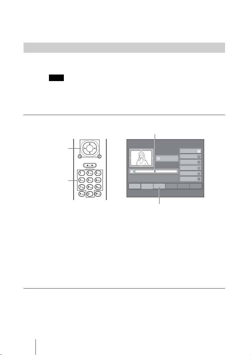
1 Select “CFwdAll” using the V, v, B or b button and the PUSH ENTER
button on the Remote Commander.
2 Enter the number of the remote party to whom you want to transfer all calls
in the text box using the number buttons on the Remote Commander.
When the number has been entered, the message “Forwarded to xxxx
(destination number)” is displayed.
Now every call incoming through the first telephone line is automatically
transferred to the specified destination.
To cancel the “CFwdAll” feature
Select “CFwdAll” using the V, v, B or b button and the PUSH ENTER button
on the Remote Commander. The “CFwdAll” feature is cancelled and the
message changes to “Your current options.”
22:56 10/12/2005
2001
Menu
INFORMATION
2
NewCall
3
CFwdAll
1
Redial
12345678
12345678
12345678
ABCDEFGH
ABCDEFGH
ABCDEFGH
456
CFwdAll
50 Transferring a Call – Transfer/DirTrfr/CFwdAll
Page 51
Parking a Call in the SCCP Server – Park
You can temporarily park a call at the park number registered on the SCCP
server, and pick it up from another Video Communication System or another
phone.
The park number can be registered on the SCCP server. For details on
registration, consult the server administrator.
To park a call
Communication menu
V/v/B/b and
PUSH ENTER
buttons
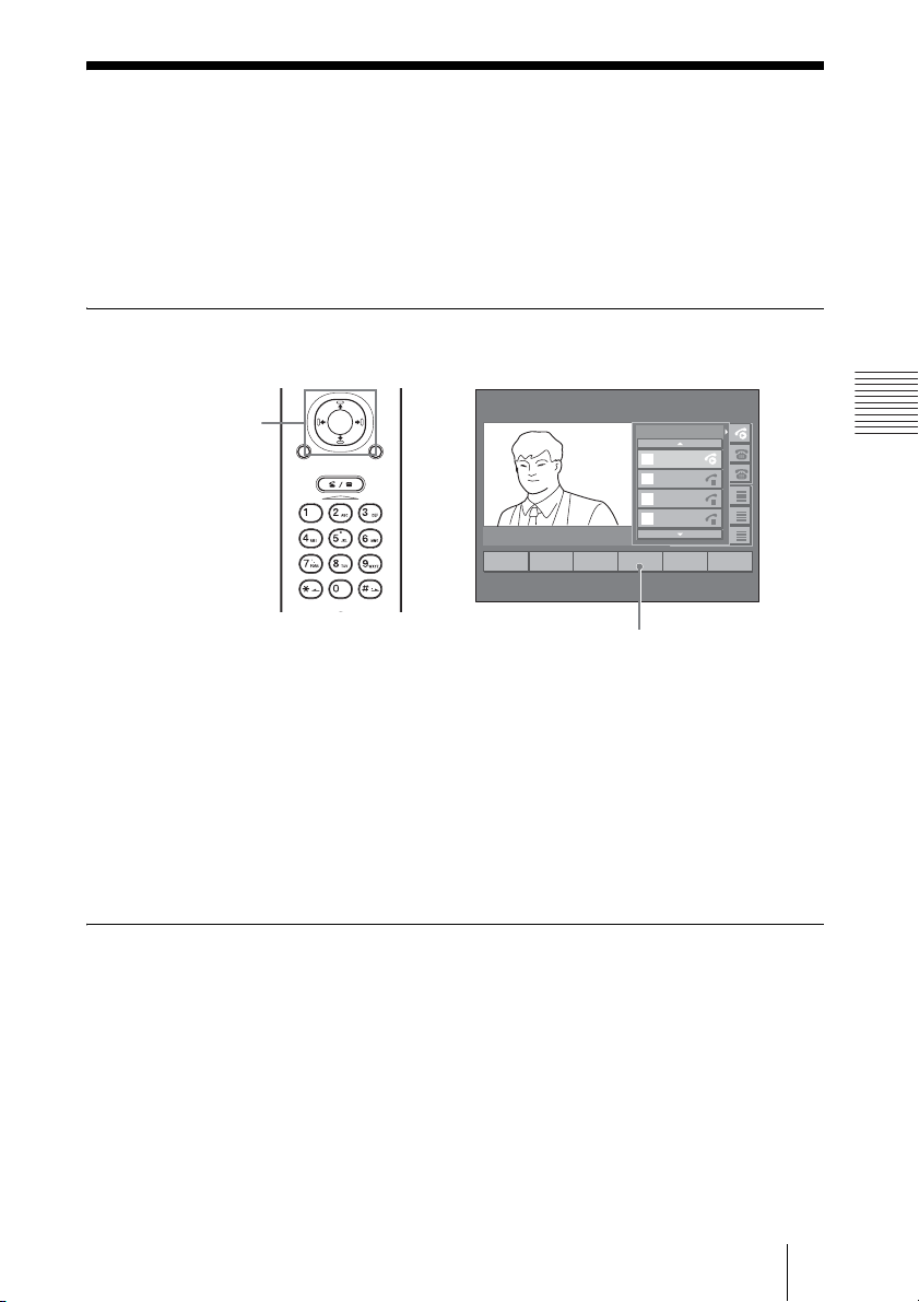
1 Press the PUSH ENTER button on the Remote Commander during
communication with a remote party.
The communication menu appears on the monitor screen.
PUSH
ENTER
RETURN MENU
CONNECT/
DISCONNECT
HELP
12345678
12345678
12345678
From
1
2345
12345678
From
2
6789
To
ABCDEFGH
3
ABCDEFGH
From
ABCDEFGH
4
ABCDEFGH
2
EndCall
3
Transfer
1
Hold
ABCDEFGH
4
Park5Confrn6More
Park
Chapter 3: Daily Videoconference
2 Select “Park” using the V, v, B or b button and the PUSH ENTER button
on the Remote Commander.
The current call is parked at the registered park number and the message
“Parked at xxxx (park number)” is displayed. The monitor screen then returns
to the launcher menu.
To pick up the parked call
Enter the park number in the text box of the launcher menu. The system
connects to the parked remote party and you can now start a videoconference
with that party.
51Parking a Call in the SCCP Server – Park
Page 52
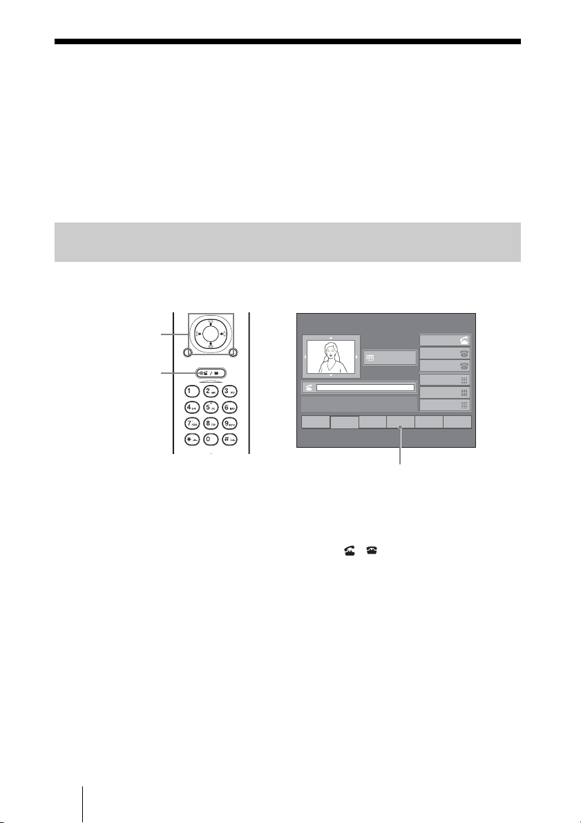
Receiving a Call Directed to Another
Terminal – PickUp / GPickUp
When multiple terminals including this system have been separated into
groups and the group numbers have been assigned, you can answer a call
directed to another terminal.
The groups and group numbers can be registered on the SCCP server. For
details on registration, consult the server administrator.
Receiving a Call Directed to Another Terminal in Your Group –
PickUp
When telephone line 1 is off the hook
V/v/B/b and
PUSH ENTER
buttons
CONNECT/
DISCONNECT
button
PUSH
ENTER
RETURN MENU
CONNECT/
DISCONNECT
HELP
22:56 10/12/2005
2001
Menu
INFORMATION
2
EndCall
3
CFwdAll
1
Redial
12345678
12345678
12345678
ABCDEFGH
ABCDEFGH
ABCDEFGH
4
PickUp5GPickUp6MeetMe
PickUp
1 There is an incoming call to a terminal in your group.
A ringer tone sounds on the terminal.
2 Press the CONNECT/DISCONNECT ( / ) button on the Remote
Commander of this system.
The system enters off the hook.
3 Select “PickUp” using the V, v, B or b button and the PUSH ENTER
button on the Remote Commander.
The message “From xxxx (number of incoming call)” is displayed and the call
incoming display appears.
4 Select “Answer” using the V, v, B or b button and the PUSH ENTER
button on the Remote Commander.
The system connects to the remote party and you can now start a
videoconference with that party.
52 Receiving a Call Directed to Another Terminal – PickUp / GPickUp
Page 53
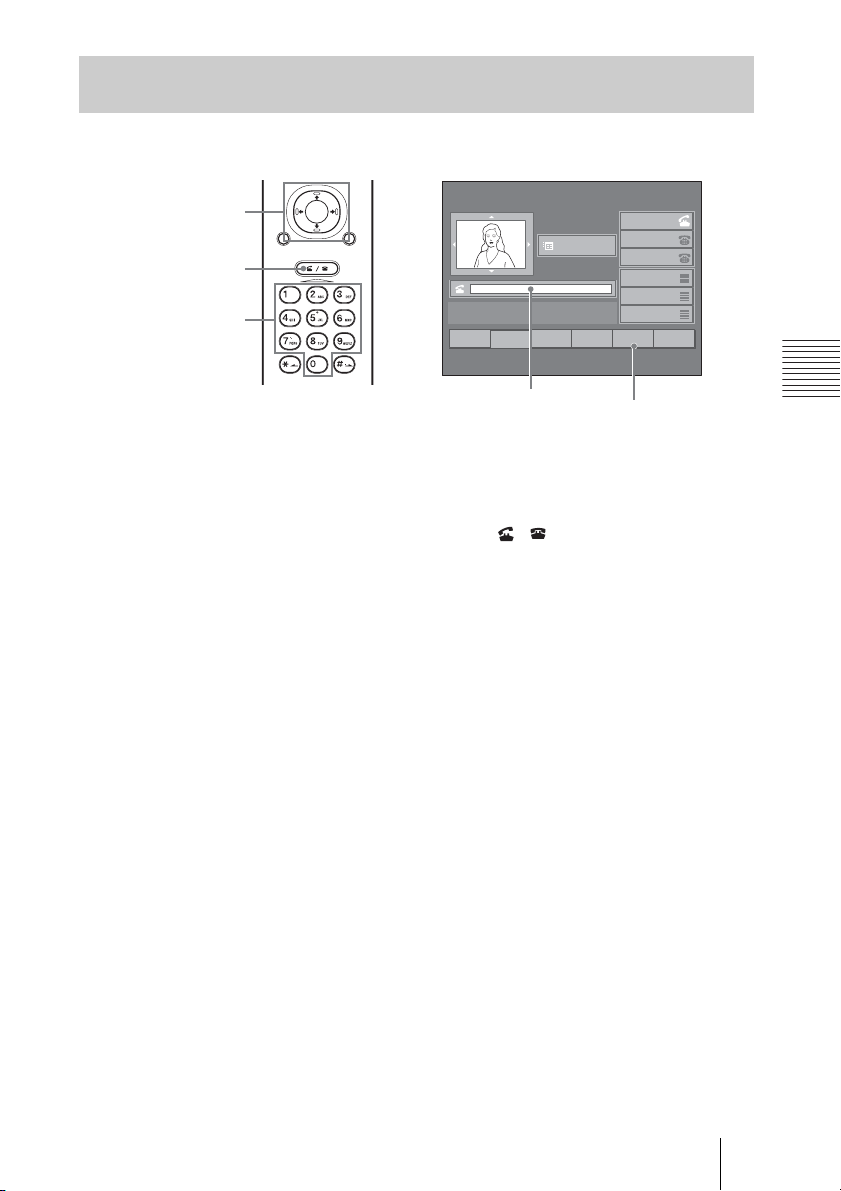
Receiving a Call Directed to a Terminal in Another Group –
GPickUp
When telephone line 1 is off the hook
V/v/B/b and
PUSH ENTER
buttons
CONNECT/
DISCONNECT
button
Number buttons
PUSH
ENTER
RETURN MENU
CONNECT/
DISCONNECT
HELP
22:56 10/12/2005
2001
Menu
INFORMATION
2
EndCall
3
CFwdAll
1
Redial
Text box
12345678
12345678
12345678
ABCDEFGH
ABCDEFGH
ABCDEFGH
4
PickUp5GPickUp6MeetMe
GPickUp
1 There is an incoming call to a terminal in a group other than yours.
A ringer tone sounds on the terminal.
2 Press the CONNECT/DISCONNECT ( / ) button on the Remote
Commander of this system.
The system enters off the hook.
3 Select “GPickUp” using the V, v, B or b button and the PUSH ENTER
button on the Remote Commander.
Chapter 3: Daily Videoconference
4 Enter the number of the group to which the terminal with an incoming call
belongs in the text box.
The message “From xxxx (number of the incoming call)” is displayed and the
call incoming display appears.
5 Select “Answer” using the V, v, B or b button and the PUSH ENTER
button on the Remote Commander.
The system connects to the remote party and you can now start a
videoconference with that party.
53Receiving a Call Directed to Another Terminal – PickUp / GPickUp
Page 54
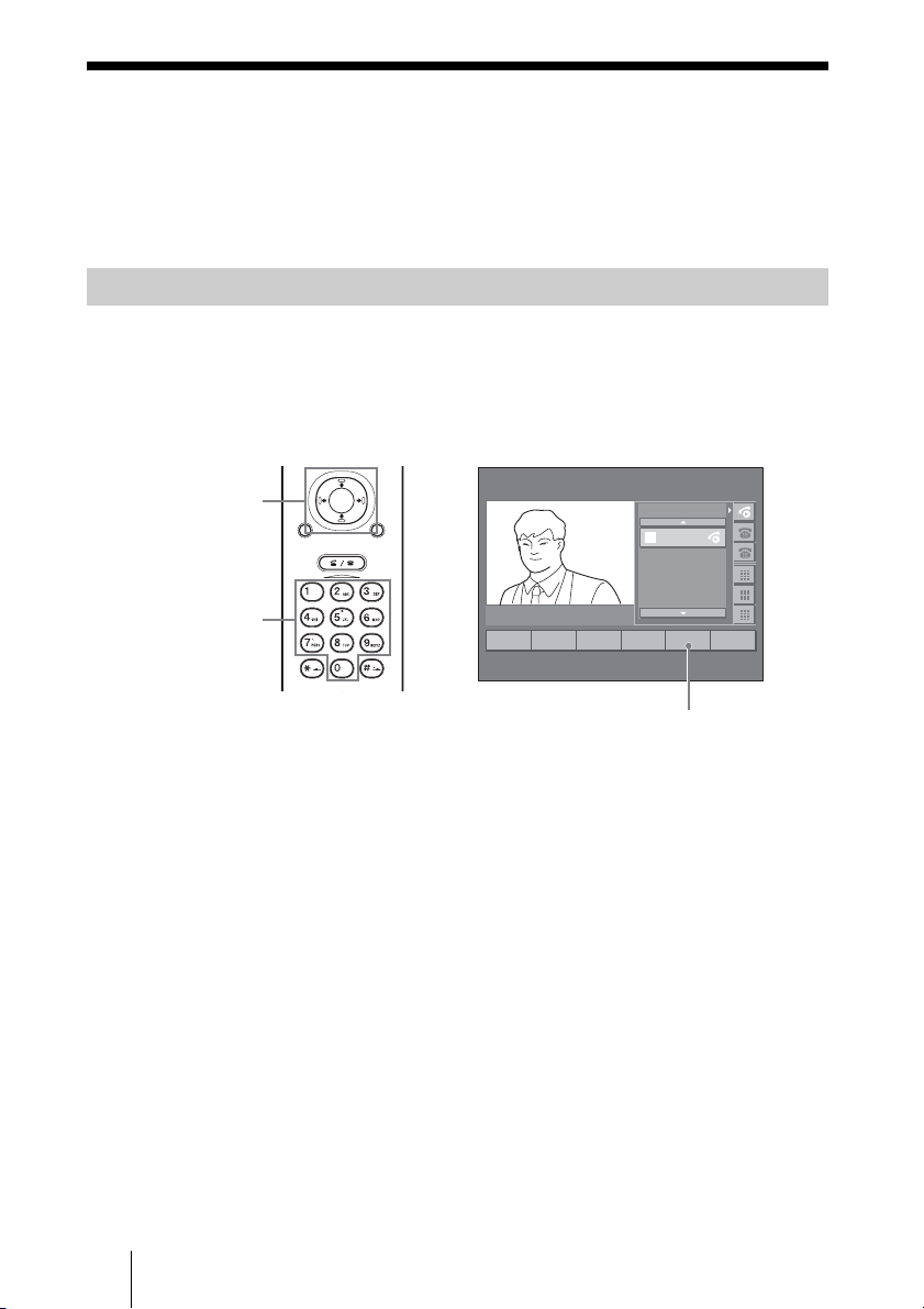
Conducting a Multipoint
Videoconference – Confrn/Join
You can conduct a multipoint videoconference among Video Communication
Systems and phones.
Starting a Multipoint Videoconference – Confrn
This section explains how to start a multipoint videoconference and have
remote parties join in the conference one by one when you are the host of the
conference.
Communication menu
V/v/B/b and
PUSH ENTER
buttons
Number buttons
PUSH
ENTER
RETURN MENU
CONNECT/
DISCONNECT
HELP
12345678
1
2
3
4
2
1
EndCall
Hold
3
Transfer
4
Park5Confrn6More
12345678
12345678
From
2345
12345678
From
6789
To
ABCDEFGH
ABCDEFGH
From
ABCDEFGH
ABCDEFGH
ABCDEFGH
Confrn
1 Call the first remote party or receive the call from the first remote party,
and establish communication.
For details of the operations, see “Starting a Conference by Calling a
Remote Party – NewCall” on page 32 or “Receiving a Call from a Remote
Party – Answer” on page 41.
2 To have the second or later remote party join in the conference, press the
PUSH ENTER button on the Remote Commander.
The communication menu appears on the monitor screen.
3 Select “Confrn” using the V, v, B or b button and the PUSH ENTER
button on the Remote Commander.
The remote party currently in communication enters hold mode, and a text box
appears on the monitor screen.
54 Conducting a Multipoint Videoconference – Confrn/Join
Page 55
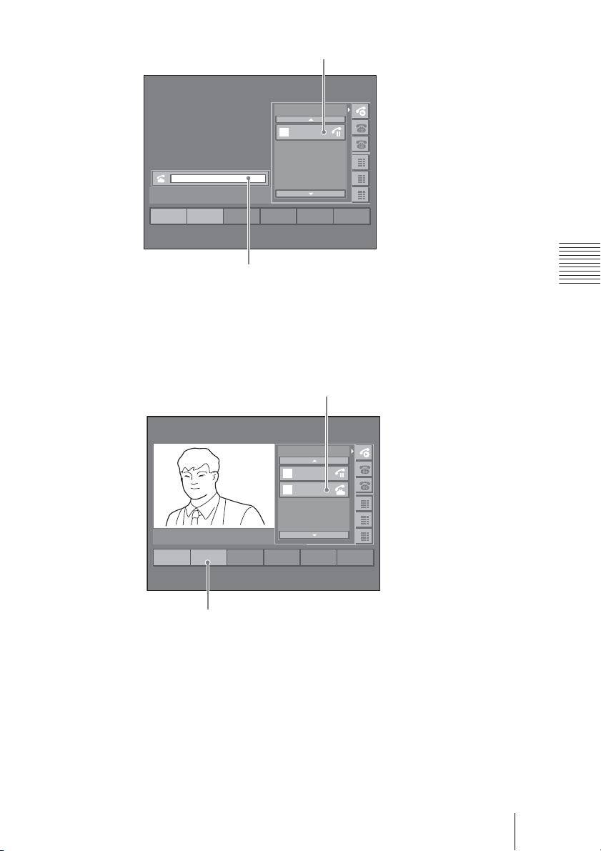
Remote party currently in hold mode
12345678
12345678
12345678
From
1
2345
12345678
From
2
6789
To
ABCDEFGH
3
ABCDEFGH
From
ABCDEFGH
4
ABCDEFGH
ABCDEFGH
1
Redial2Transfer
4563
Text box
4 Enter the number of a new remote party whom you want to have join in the
conference in the text box using the number buttons on the Remote
Commander.
Presssing a number button allows you to enter a number in the text box.
When the system connects to the remote party, the following display appears.
Newly connected remote party
12345678
12345678
12345678
From
1
2345
12345678
To
2
6789
To
ABCDEFGH
3
ABCDEFGH
From
ABCDEFGH
4
ABCDEFGH
ABCDEFGH
1
EndCall2Confrn
4563
Chapter 3: Daily Videoconference
Confrn
5 Select the icon of the connected remote party (in off-hook mode) using the
V, v, B or b button on the Remote Commander.
6 Press the B or b button on the Remote Commander to select a function key.
7 Select “Confrn” using the B or b button and the PUSH ENTER button on
the Remote Commander.
You can start a videoconference with three parties now.
8 To have the next remote party to join in the conference, repeat steps 3 to 6.
55Conducting a Multipoint Videoconference – Confrn/Join
Page 56
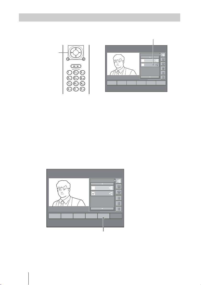
Having a Remote Party in Hold Mode Join in the Conference – Join
You can have a remote party whose call is put on hold join in the conference.
Remote party to join
Communication menu
V/v/B/b and
PUSH ENTER
buttons
PUSH
ENTER
RETURN MENU
CONNECT/
DISCONNECT
HELP
12345678
12345678
12345678
From
1
2345
12345678
From
2
6789
To
ABCDEFGH
3
ABCDEFGH
From
ABCDEFGH
4
ABCDEFGH
2
EndCall
3
Transfer
1
Hold
ABCDEFGH
4
Park5Confrn6More
1 Press the PUSH ENTER button on the Remote Commander during
communication with a remote party.
The communication menu appears on the monitor screen.
2 Select the icon of another remote party (in hold mode) whom you want to
have join in the conference using the V, v, B or b button on the Remote
Commander.
3 Press the B or b button on the Remote Commander to select a function key.
4 Select “Select” using the B or b button and the PUSH ENTER button on
the Remote Commander.
A checkmark is displayed on the selected remote party.
12345678
12345678
12345678
From
1
2345
12345678
From
6789
To
ABCDEFGH
3
ABCDEFGH
From
ABCDEFGH
4
ABCDEFGH
ABCDEFGH
1
Resume
2
NewCall
3
DirTrfr
4
Select5Join
6
More
Join
5 Press the B or b button on the Remote Commander to select a function key.
6 Select “Join” using the B or b button and the PUSH ENTER button on the
Remote Commander.
The selected remote party can now join in the conference.
56 Conducting a Multipoint Videoconference – Confrn/Join
Page 57
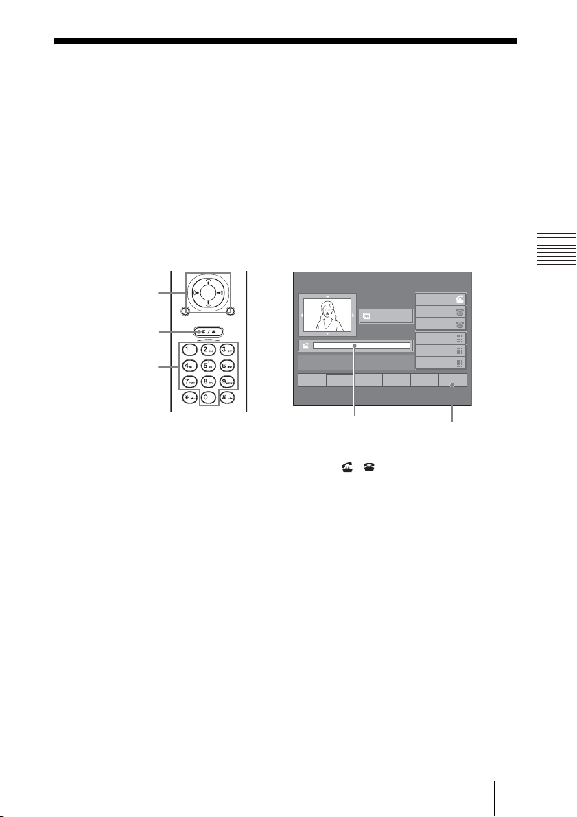
Conducting a MeetMe Conference –
MeetMe
If you dial the MeetMe number registered in the SCCP server, you can hold a
multipoint videoconference among Video Communication Systems and
phones.
This section explains how to start a multipoint videoconference when you are
the host of the conference.
The MeetMe number can be registered on the SCCP server. For details on
registration, consult the server administrator.
When telephone line 1 is off the hook
V/v/B/b and
PUSH ENTER
buttons
CONNECT/
DISCONNECT
button
Number buttons
PUSH
ENTER
RETURN MENU
CONNECT/
DISCONNECT
HELP
22:56 10/12/2005
2001
Menu
INFORMATION
2
EndCall
3
CFwdAll
1
Redial
Text box
12345678
12345678
12345678
ABCDEFGH
ABCDEFGH
ABCDEFGH
4
PickUp5GPickUp6MeetMe
MeetMe
Chapter 3: Daily Videoconference
1 Press the CONNECT/DISCONNECT ( / ) button on the Remote
Commander of this system.
The system enters off the hook.
2 Select “MeetMe” using the V, v, B or b button and the PUSH ENTER
button on the Remote Commander.
3 Enter the MeetMe number in the text box using the number buttons on the
Remote Commander.
Presssing a number button allows you to enter a number in the text box.
The local picture is displayed in full screen and the MeetMe conference starts.
4 After the host has started the MeetMe conference, each party can join in
the conference by dialing the same MeetMe number.
When multiple terminals join in the conference, the picture of the site with the
loudest voice is displayed in full screen on all the terminals.
57Conducting a MeetMe Conference – MeetMe
Page 58
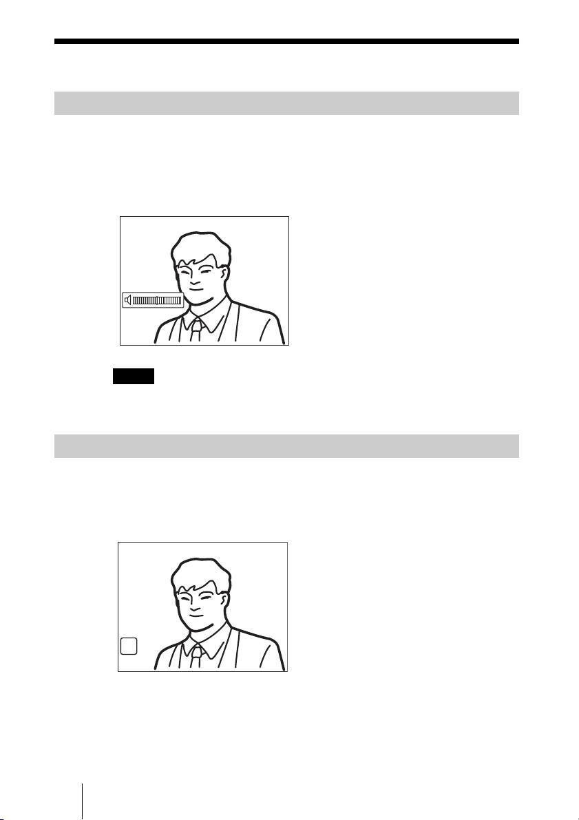
Adjusting the Sound
Adjusting the Volume
You can adjust the volume of the sound to be received from a remote party.
Press the VOLUME + button on the Remote Commander to increase the
volume, VOLUME – button to decrease it. The volume level indicator appears
on the monitor screen. The indicator will automatically disappear if you do not
operate the buttons for a certain time.
Notes
• You need to set the volume of the TV monitor to an appropriate level first.
• If feedback caused by increasing the volume occurs, decrease the volume.
Cutting Off the Sound Momentarily – Muting Function
You can momentarily cut off the sound to be sent to the remote party.
Press the MIC ON/OFF button on the Remote Commander.
The sound of the local party is not heard by the remote party. The “MIC OFF”
indicator appears on the monitor screen.
MIC
OFF
To restore the sound
Press the MIC ON/OFF button again.
The “MIC OFF” indicator disappears.
58 Adjusting the Sound
Page 59

Synchronizing Audio and Video – Lip Sync Function
During the conference a time lag may occur between the sound and picture to
be sent to the remote party.
When you set “Lip Sync” to “On” in the Audio Setup menu, the system adjusts
to synchronize audio and video. However, this may delay transmission of
audio synchronized with video.
For the “Lip Sync” setting, see “Audio Setup Menu” on page 26.
Note
To enable the Lip Sync function of the remote party, you have to ask them to do so.
Reducing Echo – Echo Canceler
The Communication Terminal is equipped with the Echo Canceler, allowing
the echo that occurs during audio transmission to be reduced.
Setting “Echo Canceler” to “Internal” in the Audio Setup menu activates the
built-in echo canceler. If you set it to “External”, you can activate the eco
canceler of the equipment connected to the system.
For the “Echo Canceler” setting, see “Audio Setup Menu” on page 26.
Chapter 3: Daily Videoconference
59Adjusting the Sound
Page 60
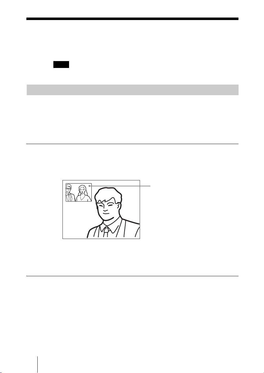
Adjusting the Camera
You can adjust the image shot by the local camera that is sent to the remote
party to obtain the desired angle and size.
Note
You cannot control the remote camera with this system.
Adjusting the Camera Angle and Zoom
Determine the angle of view and the size of the picture to be displayed by
adjusting the angle and zoom.
You can make adjustments in the monitor screen screen during communication
and in the launcher menu when not in communication. You can also make
adjustments using the Camera menu.
To make adjustment during communication
1 Press the V, v, B or b button to adjust the camera angle.
The picture whose camera angle is adjusted is displayed in the small window.
Adjusted picture
2 Use the ZOOM button to zoom in or out.
Press the ZOOM T (Telephoto) button to zoom in (to enlarge image), and the
ZOOM W (Wide angle) button to zoom out (to obtain wider range of image).
To make adjustment using the launcher menu while not in communication
1 Use the V, v, B or b button to select the screen (screen frame becomes
yellow), then press the PUSH ENTER button.
The color of the screen frame changes, then you can adjust the camera angle
and zoom.
60 Adjusting the Camera
Page 61
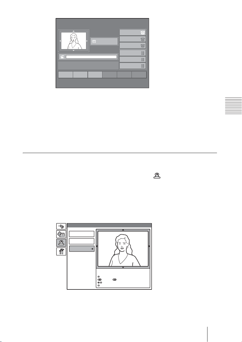
1
Redial
2
NewCall
22:56 10/12/2005
2001
Menu
INFORMATION
3
456
CFwdAll
12345678
12345678
12345678
ABCDEFGH
ABCDEFGH
ABCDEFGH
2 Press the V, v, B or b button to adjust the camera angle so that the desired
angle of view is obtained.
3 Use the ZOOM button to zoom in or out.
Press the ZOOM T button to zoom in (to enlarge image), and the ZOOM W
button to zoom out (to obtain wider range of image).
4 Press the PUSH ENTER button.
To make adjustment using the Camera menu
1 Press the MENU button on the Remote Commander to display the Setup
menu, then press the V or v button to select (camera) icon.
The Camera menu appears.
2 Use the V, v, B or b button to select “Adjustments”, then press the PUSH
ENTER button.
The color of the screen frame changes, then you can adjust the camera angle
and zoom.
Camera
Preset Save
Preset Load
Adjustments
Use the following Remote Commander buttons to
adjust the camera.
: Auto adjustment On.
: Focus+. : Focus : Brightness.
: Backlight On/Off.
Chapter 3: Daily Videoconference
3 Press the V, v, B or b button to adjust the camera angle so that the desired
angle of view is obtained.
61Adjusting the Camera
Page 62
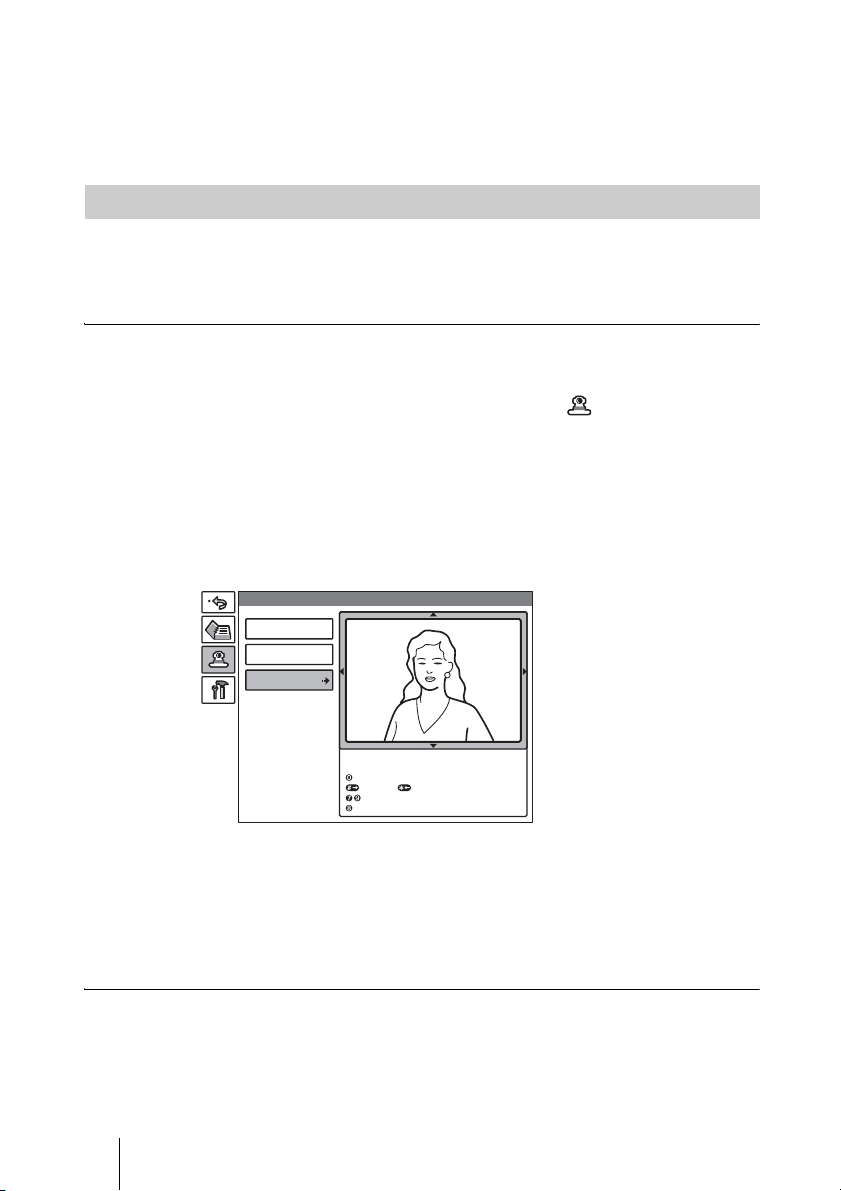
4 Use the ZOOM button to zoom in or out.
Press the ZOOM T button to zoom in (to enlarge image), and the ZOOM W
button to zoom out (to obtain wider range of image).
5 Press the PUSH ENTER button.
Adjusting the Focus and Brightness
Normally, the focus and brightness are automatically adjusted to obtain
optimum levels. You can also adjust then manually.
It is recommended that the focus and brightness be adjusted automatically.
To set the system to camera adjustment mode
1 Press the MENU button on the Remote Commander to display the Setup
menu, then press the V or v button to select the (camera) icon.
The Camera menu appears.
2 Use the V, v, B or b button to select “Adjustments”, then press the PUSH
ENTER button.
The color of the screen frame changes, then you can adjust the camera angle
and zoom.
The guidance for operations will be displayed under the screen.
Camera
Preset Save
Preset Load
Adjustments
Use the following Remote Commander buttons to
adjust the camera.
: Auto adjustment On.
: Focus+. : Focus : Brightness.
: Backlight On/Off.
To display the picture to fill the display
To display the picture in full screen while the Camera menu is displayed, select
“Adjustments”, then press the PinP button on the Remote Commander. To
cancel the full screen mode, press the RETURN button or PinP button on the
Remote Commander.
To adjust the focus automatically
Press the number button 0 on the Remote Commander.
The “Auto Camera” indicator appears and the focus and brightness are
automatically adjusted.
62 Adjusting the Camera
Page 63
To adjust the focus manually
Press the button on the Remote Commander repeatedly to move the
focus point further away from the camera. The “Focus Far” indicator is
displayed.
Press the button on the Remote Commander repeatedly to move the focus
point closer to the camera. The “Focus Near” indicator is displayed.
To adjust the brightness
Press the number button “9” on the Remote Commander repeatedly to make
the picture brighter. The “Brightness +” indicator is displayed.
Press the “7” button on the Remote Commander repeatedly to make the picture
darker. The “Brightness –” indicator is displayed.
To shoot the picture with backlight compensation
Use backlight compensation when shooting a subject with bright background.
Each time you press the “8” button on the Remote Commander, the backlight
compensation is activated or deactivated. When it is activated, the “Backlight
On” indicator is displayed. When it is deactivated, the “Backlight Off”
indicator is displayed.
Presetting the Angle and Zoom Settings
Up to six settings for camera angle and zoom can be registered in the preset
memory. Once you have stored the settings, you can easily recall them to move
the camera.
You can preset the settings in the monitor screen while in communication, and
in the launcher menu while not in communication. You can also do so using
the Camera menu.
To preset the setting in the monitor screen while in communication
1 Adjust the camera angle and zoom.
Use the V, v, B or b button to adjust the camera angle, and the ZOOM button
to adjust the zoom.
2 Keep one of the number buttons 1–6 pressed.
The angle and zoom setting is stored in the selected number button, and the
message “Registered to Preset number 1 (–6).” appears.
Chapter 3: Daily Videoconference
To preset the setting in the launcher menu while not in communication
1 Adjust the camera angle and zoom in the launcher menu.
Use the V, v, B or b button to select the screen and press the PUSH ENTER
button, then press the V, v, B or b button to adjust the angle and the ZOOM
buttons to adjust the zoom.
63Adjusting the Camera
Page 64
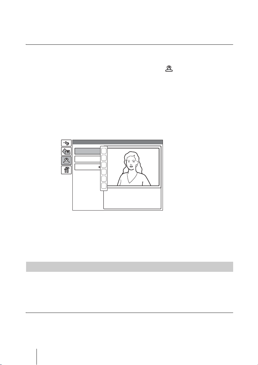
2 Keep one of the number buttons 1–6 pressed.
The angle and zoom setting is stored in the selected number button, and the
message “Registered to Preset number 1 (–6).” appears.
To preset the setting using the Camera menu
1 Press the MENU button on the Remote Commander to display the Setup
menu, then press the V or v button to select (camera) icon.
The Camera menu appears.
2 Use the V, v, B or b button on the Remote Commander to select “Preset
Save”, then press the PUSH ENTER button.
3 Select the preset number (1–6) with the V or v button, then press the PUSH
ENTER button.
The color of the screen frame changes, then you can adjust the zoom and
camera angle.
Camera
Preset Save
Preset Load
Adjustments
1
2
3
4
5
6
4 Adjust the angle and zoom.
Use the V, v, B or b button to adjust the camera angle, and the ZOOM button
to adjust the zoom.
5 Press the PUSH ENTER button.
The setting is registered in the selected preset number.
Recalling the Preset Angle and Zoom Setting
You can move the camera to the preset position by recalling the preset camera
angle and zoom with the monitor screen while in communication. You can do
the same with the launcher menu displayed while not in communication. Using
the Camera menu also enables movement of the camera to the preset position.
To recall the preset setting in the monitor screen while in communication
Press one of the number buttons 1–6 on the Remote Commander.
The setting of the selected preset number is recalled, and the camera moves to
the preset position. The message “Preset 1 (-6) selected” appears.
64 Adjusting the Camera
Page 65
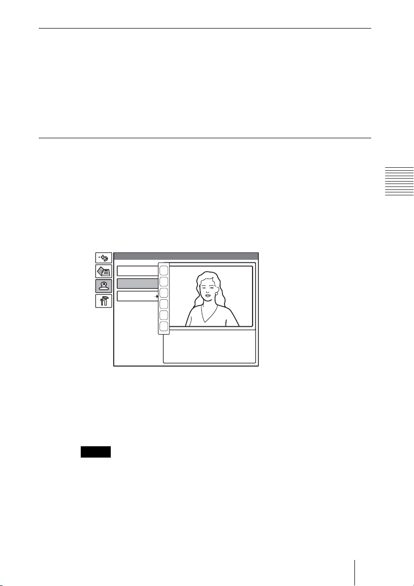
To recall the preset setting in the launcher menu while not in
communication
1 Select the screen in the launcher menu, then press the PUSH ENTER
button.
2 Press one of the number buttons 1–6 on the Remote Commander.
The setting of the selected preset number is recalled, and the camera moves to
the preset position. The message “Preset 1 (-6) selected” appears.
To recall the preset setting in the Camera menu
1 Display the Camera menu.
2 Use the V, v, B or b button on the Remote Commander to select “Preset
Load”, then press the PUSH ENTER button.
3 Press the V or v button to select the preset number (1-6) you want to recall,
then press the PUSH ENTER button.
Camera
Preset Save
Preset Load
Adjustments
1
2
3
4
5
6
Use the following Remote Commander buttons to
adjust the camera.
: Auto adjustment On.
: Focus+. : Focus-
: Brightness.
: Backlight On/Off.
Chapter 3: Daily Videoconference
The setting of the preset number is recalled and the camera moves to the
position of that setting.
On backup
The built-in lithium battery enables retention of the memories such as preset
camera adjustments even if the Communication Terminal is turned off.
Notes
• The built-in lithium battery is kept charged as long as the system is operated. If the
system is not used for a long time, the battery is gradually discharged. It will be
completely discharged when you do not use the system for 12 weeks. To retain the
memories, recharge the battery.
• To recharge the battery, connect the camera to the Communication Terminal and
leave both units with the powers on for about 48 hours.
65Adjusting the Camera
Page 66
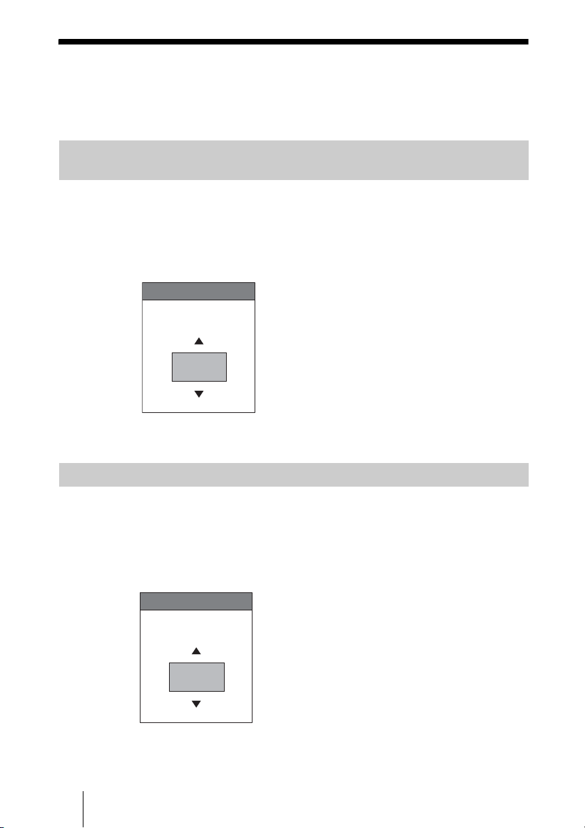
Selecting the Input Picture and Sound
This section describes how to switch the picture displayed on the monitor
screen, and how to switch the input picture and sound.
Switching the Displayed Picture Between the Local and Remote
Pictures
1 Press the FAR/NEAR button on the Remote Commander.
The Display Control menu appears.
2 Use the V, v, B or b button on the Remote Commander to select “Near” or
“Far” under “Display”.
Display Control
Display
Far
3 Press the PUSH ENTER button on the Remote Commander.
Selecting the Input Picture
1 Press the VIDEO INPUT SELECT button on the Remote Commander.
The Video Input Select menu appears.
2 Use the V, v, B or b button on the Remote Commander to select the video
input on the local site.
Video Input Select
Near
Main
Main: Select the picture shot by the Camera.
Object: Select the picture from the optional PCS-DS150/DS150P Document
Stand.
66 Selecting the Input Picture and Sound
Page 67

AUX 1: Selects the picture from the equipment connected to the VIDEO IN
AUX 1 connector.
AUX 2: Select the picture from the equipment connected to the VIDEO IN
AUX 2 connector.
3 Press the PUSH ENTER button on the Remote Commander.
To change the video input name displayed in the Video Input Select menu
If you label “Main”, “Object”, “AUX1” or “AUX2” under “Custom Input
Label” in Page 3 of the General Setup menu as a desired name, the displayed
input name in the Video Input Select menu will be changed to the label when
selecting the video input in step 2 above.
For example, you can label as Main, Document, Camera2, None.
For details on “Custom Input Label”, see “Page 3/3” in the General Setup
menu on page 25.
Switching the Sound to Be Sent to the Remote Party
You can switch the sound sent to the remote party between the sound from the
microphone and that from the connected equipment. Use “Input Select” in the
Audio Setup menu.
For details on the “Input Select” setting, see page 26.
Chapter 3: Daily Videoconference
67Selecting the Input Picture and Sound
Page 68
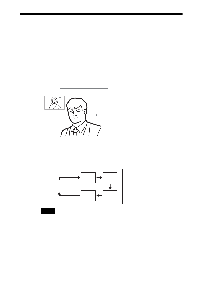
Monitoring the Local Picture as a
Window Picture – PinP Feature
You can display the picture shot by the local camera on the monitor screen as
a window picture (Picture-in-Picture). This function enables you to check
how your own party is monitored on the remote site.
To display the window picture
Press the PinP button on the Remote Commander during communication.
The local picture is displayed as a window picture.
Local picture
Remote picture
To change the location of the window picture
Each press of the PinP button changes the location of the window as follows:
Monitor screen
The window picture
disappears.
Notes
• The window picture is displayed in the same location as it was last located. The
window picture is not displayed if it was not displayed last.
• The window picture is not available while not in communication with the remote
party.
To display the remote picture as a window picture
Press the FAR/NEAR button on the Remote Commander to open the Display
Control menu and select “Near” under “Display” when the local picture is
displayed as a window picture. The remote picture is displayed as a window
picture with the local picture as the main picture.
68 Monitoring the Local Picture as a Window Picture – PinP Feature
Page 69

Chapter 4:
Videoconference
With Optional
Equipment
This chapter describes the various videoconferences using the optional
equipment in addition to the components contained in the PCS-1/1P Video
Communication System.
Using Two Monitors – Dual Monitor
The Communication Terminal enables you to connect two monitors. One
monitor can be used exclusively for monitoring motion pictures. (Dual
Monitor system)
To connect the second monitor
Connect the second monitor to the VIDEO OUT MONITOR SUB or RGB
OUT connector on the Communication Terminal.
When you are using Sony monitors, insert the IR repeater under the remote
sensor of the second monitor and connect it to the IR OUT 2 jack on the
Communication Terminal.
Chapter 4: Videoconference With Optional Equipment
69Using Two Monitors – Dual Monitor
Page 70
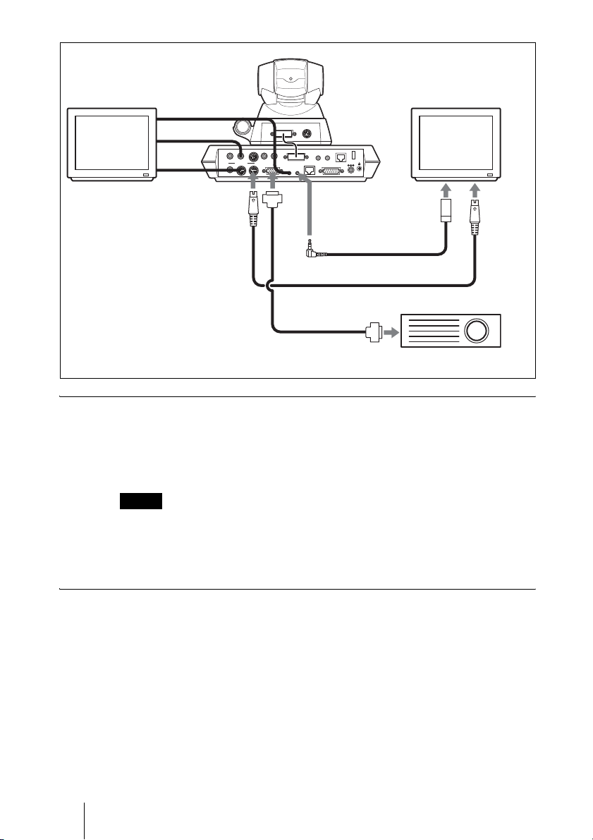
First monitor
AUDIO OUT
(MIXED)
VIDEO OUT
MAIN–MONITOR–SUB
AUX
to VIDEO OUT
MONITOR SUB
Signal cable
(not supplied)
Activating dual monitor system
Set “Dual Monitor” to “On” in Page 1 of the General Setup menu. The default
setting is “Off” (page 24).
When set to “On”, the first monitor is used exclusively for monitoring motion
pictures while still images are displayed on the second monitor.
AUDIO IN
AUX1–
VIDEO IN
–AUX2
CAMERA UNIT MIC
RGB OUT XXXXXX
IR OUT
12
to
RGB
OUT
Second monitor
XXXX WHITE
(PLUG IN POWER)
BOARD
12
100BASE-TX
10BASE-T
to IR
OUT 2
DC 19.5V
Under the
remote
sensor
IR repeater (supplied)
S-video connecting cable (not supplied)
Second monitor (projector, etc.)
to S-video
input
Notes
• When “Dual Monitor” is set to “Off”, still images will be displayed on the first
monitor screen.
• When “Dual Monitor” is set to “On”, the local picture is displayed on the second
monitor screen while not in communication.
To display the picture on the second monitor screen
Set “Sub Monitor Out” to “VIDEO OUT” or “RGB OUT” in Page 1 of the
General Setup menu. (See page 24.)
VIDEO OUT: Outputs a signal to the monitor connected to the VIDEO OUT
MONITOR SUB connector on the Communication Terminal.
RGB OUT: Outputs a signal to the monitor connected to the RGB OUT
connector on the Communication Terminal.
70 Using Two Monitors – Dual Monitor
Page 71

To view the picture as a window picture
When you press the PinP button on the Remote Commander during
communication, the picture will be displayed as a window picture on the first
monitor screen.
Note
You cannot display a window picture on the second monitor screen.
Chapter 4: Videoconference With Optional Equipment
71Using Two Monitors – Dual Monitor
Page 72
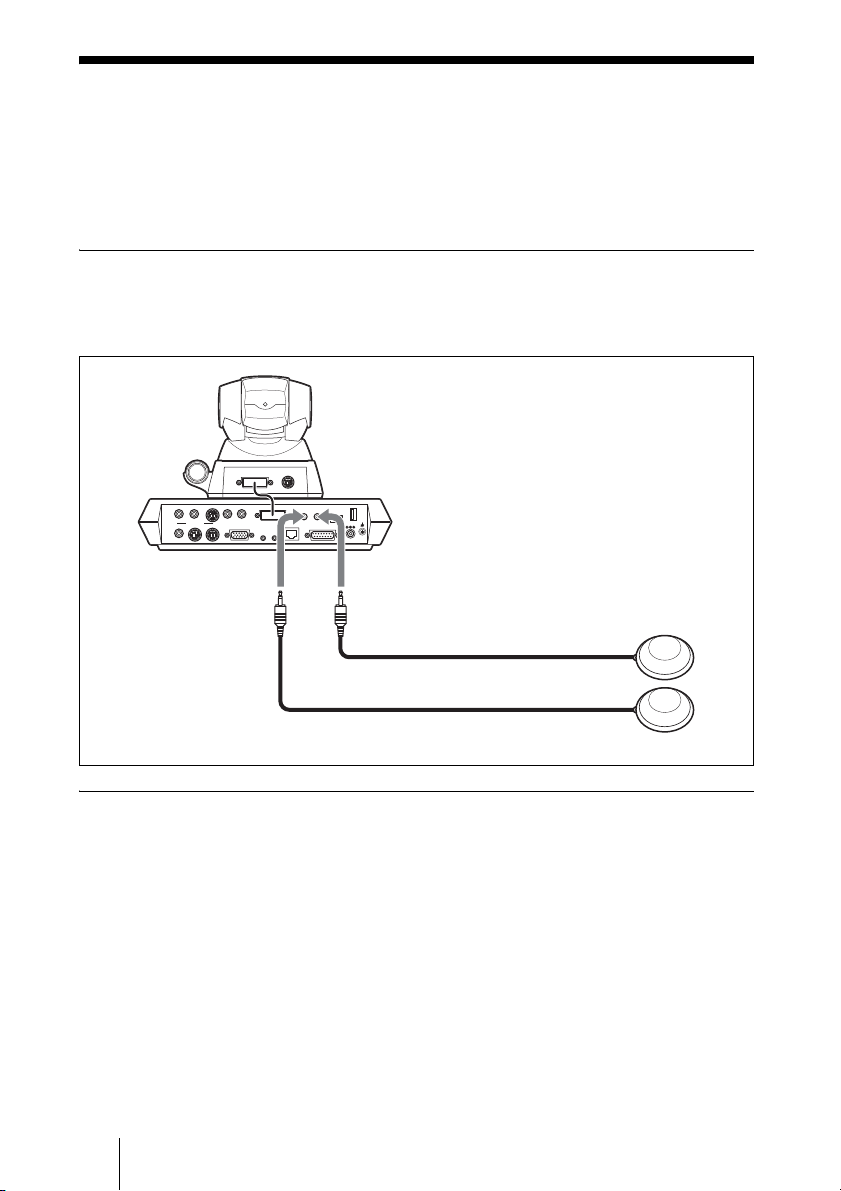
Using Multiple Microphones
The microphone built in the PCS-C1/C1P Camera Unit is assumed to be used
to conduct a conference among about three participants. You can connect the
optional PCS-A1 or PCSA-A3 microphone to the system, allowing more
persons to participate in the conference.
To connect the optional microphones
Connect the optional microphones to the MIC 1 and MIC 2 connectors on the
Communication Terminal. Power is supplied to the microphones from the
Terminal.
TERMINAL VISCA OUT
AUDIO OUT
AUDIO IN
AUX1–
VIDEO IN
–AUX2
CAMERA UNIT MIC
(PLUG IN POWER)
ISDN UNIT WHITE
12
(MIXED)
VIDEO OUT
AUX
MAIN–MONITOR–SUB
100BASE-TX
10BASE-T
RGB OUT
IR OUT
12
BOARD
DC 19.5V
DSB
to MIC 1
to MIC 2
PCS-A1 (not supplied) or PCSA-A3 microphone
(not supplied)
To use the connected microphone
Set “Mic Select” to “External” in the Audio Setup menu. (See page 26.)
In this case the built-in microphone is disabled.
Notes on installation of the microphones
• Install microphone about 50 cm away from the participants.
• Install the speakers behind the microphones.
• Place the microphone in a quiet, echo-free location.
• Install microphones away from equipment that may cause noise.
• Avoid covering a microphone with paper, etc., or moving it. If you do either,
extreme noise and echo may be heard temporarily by the remote party. In this
case, wait until the echo disappears.
72 Using Multiple Microphones
Page 73
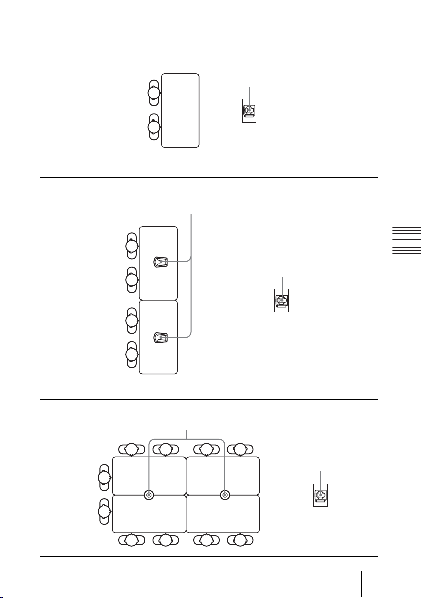
Microphone layout examples
Microphone built in the PCS-1/1P
PCSA-A3 microphones
PCS-1/1P
PCSA-A3
Chapter 4: Videoconference With Optional Equipment
PCS-1/1P
PCS-A1 microphones
PCS-A1
PCS-1/1P
73Using Multiple Microphones
Page 74
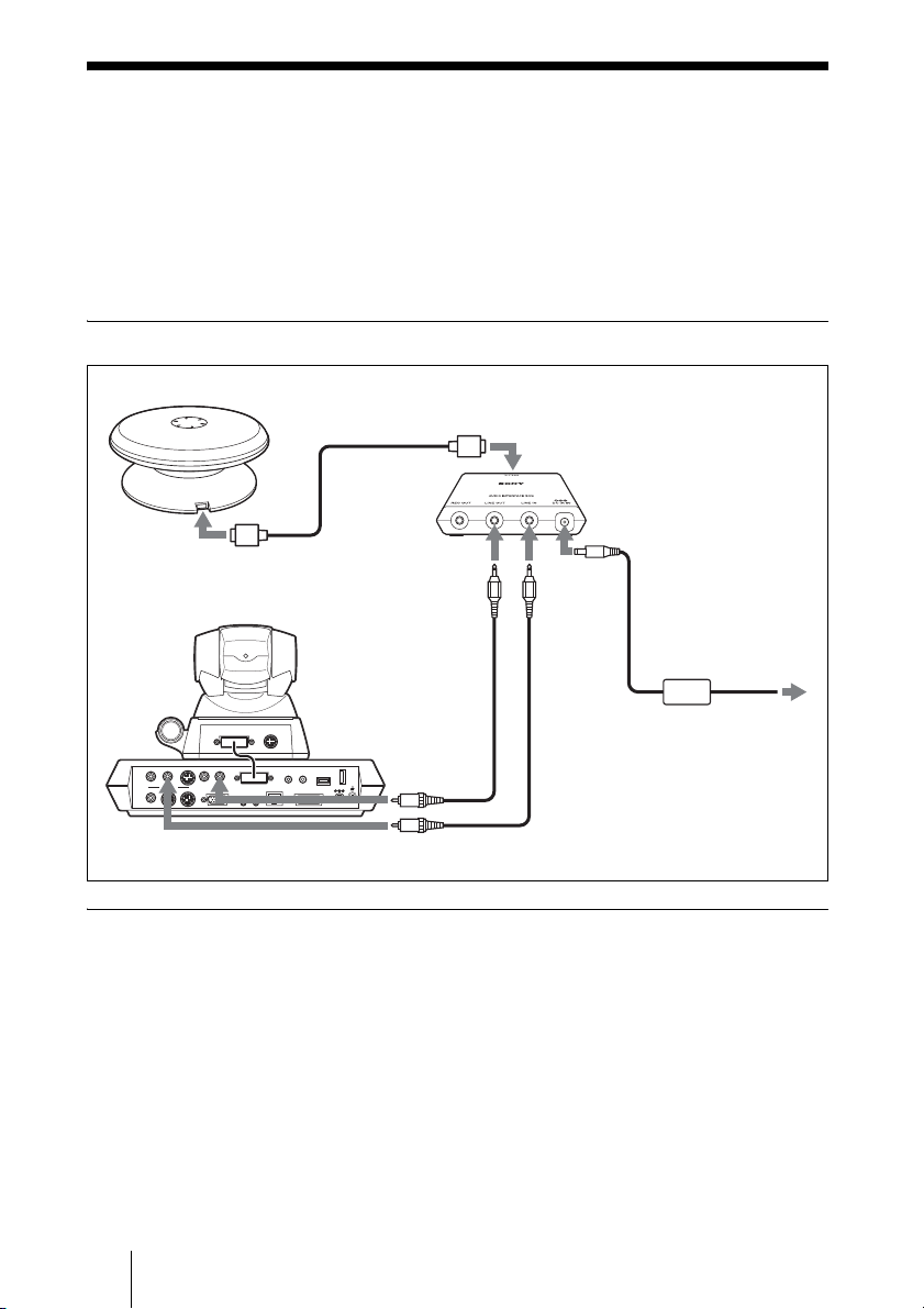
Using the Communication Transducer
(CTE)
The CTE Communication Transducer is an integrated system equipped with
uni-directional microphones and omni-directional acoustic speaker. The unit is
enabled to pick up clear voice with minimum background noise from all
directions and to emit clear sound equally in all directions.
To connect the CTE-600 Communication Transducer
CTE-600
to an input/output
connector
Connecting
cable
(supplied
with the
CTE-600)
to an input/output
connector
to LINE
OUT
Connecting cable
(not supplied)
TERMINAL VISCA OUT
AUDIO OUT
AUDIO IN
AUX1–
VIDEO IN
–AUX2
CAMERA UNIT MIC
(PLUG IN POWER)
ISDN UNIT
(MIXED)
VIDEO OUT
MAIN–MONITOR–SUB
AUX
RGB OUT
IR OUT
12
12
100BASE-TX
10BASE-T
DSB
to AUDIO
WHITE
BOARD
IN
DC 19.5V
to AUDIO OUT
To use the Communication Transducer (CTE)
• Set “CTE” in the Audio Setup menu to “AUX”. (page 26)
• Set the SYSTEM SELECT switch at the bottom of the Communication
Tranceducer to “PCS”.
Interface box
(supplied with the CTE-600)
to DC 6V
to LINE
IN
AC adaptor (supplied
with the CTE-600 )
Connecting cable
(not supplied)
to a wall
outlet
For detailed information on the Communication Transducer, refer to the
Operating Instructions that come with the Communication Transducer.
74 Using the Communication Transducer (CTE)
Page 75
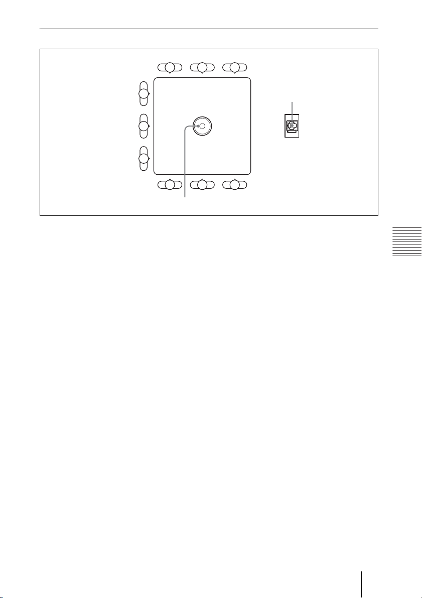
CTE layout example
PCS-1/1P
CTE-600
Chapter 4: Videoconference With Optional Equipment
75Using the Communication Transducer (CTE)
Page 76
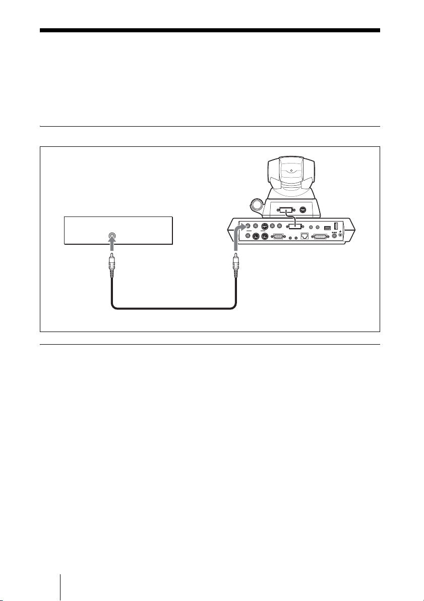
Recording Audio During a Conference
You can record the voices of the participants on both the remote and local sites
during a conference if you connect a video cassette recorder to the AUDIO
OUT (MIXED) jack on the Communication Terminal.
This is convenient for taking minutes of the conference.
To connect a video cassette recorder
Video cassette recorder, etc.
to audio
input
to AUDIO OUT (MIXED)
Audio connecting cable (not supplied)
When recording with a video cassette recorder
When a video cassette recorder is connected to both the AUDIO IN and
AUDIO OUT (MIXED) jacks, set “Recording Mute” to “On” in the Audio
Setup menu to prevent from reflecting echo on a remote party. (See page 26.)
TERMINAL VISCA OUT
AUDIO OUT
AUDIO IN
AUX1–
VIDEO IN
–AUX2
CAMERA UNIT MIC
(PLUG IN POWER)
ISDN UNIT WHITE
12
(MIXED)
VIDEO OUT
MAIN–MONITOR–SUB
AUX
100BASE-TX
10BASE-T
RGB OUT
IR OUT
12
BOARD
DC 19.5V
DSB
76 Recording Audio During a Conference
Page 77
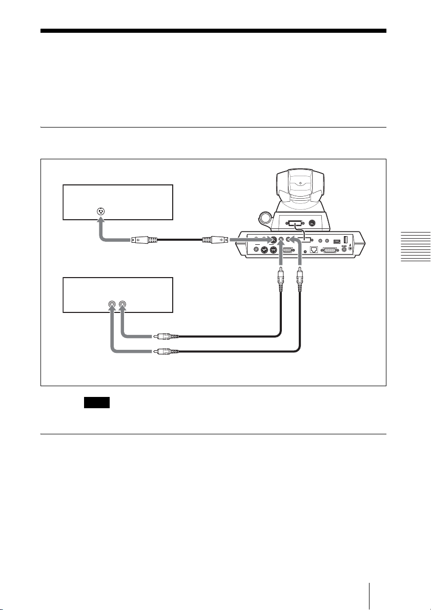
Sending Audio/Video from the External
Equipment to a Remote Party
The Communication Terminal allows you to send the picture and sound output
from the connected equipment such as a VCR to the remote party.
To connect the video equipment for input
The Communication Terminal is equipped with two video inputs.
VCR, etc.
to VIDEO IN
to S-video
AUX 1
output
S-video connecting cable (not supplied)
VCR, etc.
to video output
to audio output
Video connecting
cable (not supplied)
to VIDEO IN
Audio connecting cable
(not supplied)
Note
Be sure to connect the audio cable to either of two VCRs.
To input audio/video from external equipment
To input video
Open the Video Input Select menu by pressing the VIDEO INPUT SELECT
button on the Remote Commander, then select the desired video input from the
“Near” text box in the menu.
To input the video from the equipment connected to the VIDEO IN AUX 1 or
2 jack, choose “AUX 1” or “AUX 2”, respectively.
AUDIO OUT
(MIXED)
VIDEO OUT
MAIN–MONITOR–SUB
AUX
AUX 2
TERMINAL VISCA OUT
AUDIO IN
AUX1–
VIDEO IN
–AUX2
CAMERA UNIT MIC
(PLUG IN POWER)
ISDN UNIT WHITE
12
RGB OUT
100BASE-TX
10BASE-T
IR OUT
12
to AUDIO IN
BOARD
DC 19.5V
DSB
Chapter 4: Videoconference With Optional Equipment
To input audio
Set “Input Select” to “AUX” or “MIC + AUX” in the Audio Setup menu. (See
page 26.)
77Sending Audio/Video from the External Equipment to a Remote Party
Page 78

When set to “AUX”, the sound from the external equipment is input and the
sound from a microphone is deactivated. When set to “MIC + AUX”, both
sounds are input.
78 Sending Audio/Video from the External Equipment to a Remote Party
Page 79
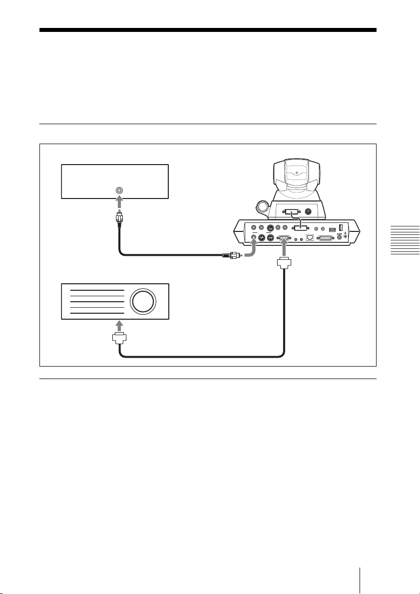
Outputting Video Signals to External
Equipment
The Communication Terminal allows you to output the video signal to the
connected external equipment such as a projector and VCR.
To connect the external video equipment for output
VCR, etc.
to Video
TERMINAL VISCA OUT
AUDIO OUT
AUDIO IN
AUX1–
VIDEO IN
–AUX2
input
Video connecting cable
(MIXED)
VIDEO OUT
MAIN–MONITOR–SUB
AUX
RGB OUT
CAMERA UNIT MIC
100BASE-TX
10BASE-T
IR OUT
12
(PLUG IN POWER)
12
ISDN UNIT WHITE
DSB
BOARD
DC 19.5V
(not supplied)
to RGB OUT
Projector, etc.
to VIDEO
OUT AUX
to RGB input
Signal cable (not supplied)
To output signals to the equipment connected to the RGB OUT connector
on the Communication Terminal
Set “Monitor Out” or “Sub Monitor Out” to “RGB OUT” in Page 1 of the
General Setup menu. (See page 24.)
When you are not using any other monitor than the equipment connected to the
RGB OUT connector, set “Dual Monitor” to “Off” in Page 1 of the General
Setup menu. When you use the equipment connected to the RGB OUT
connector as the second monitor to display a still image, etc., set “Dual
Monitor” to “On” in Page 1 of the General Setup menu. (See page 24.)
Chapter 4: Videoconference With Optional Equipment
79Outputting Video Signals to External Equipment
Page 80

Controlling the Remote System With
the Tone Signal – DTMF Transmission
The Video Communication System enables you to control the remote system
connected by transmitting the tone signal (DTMF: Dual Tone Multi
Frequency) assigned to the numbers for dialing (0-9, , ).
1 Press the button on the Remote Commander during communication.
The DTMF menu appears on the monitor screen.
2 Press one of the number buttons (0-9, , ) on the Remote Commander
corresponding to the tone signal you want to transmit to the remote party.
The tone signal will be transmitted when the button is pressed.
3 To stop transmitting the tone signal, press the PUSH ENTER button on the
Remote Commander.
The DTMF menu disappears.
80 Controlling the Remote System With the Tone Signal – DTMF Transmission
Page 81
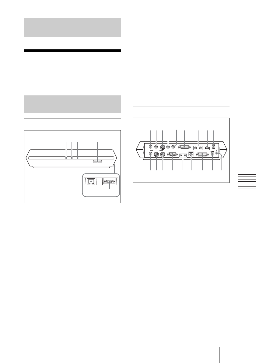
Appendix
q;qaqsqdqfqgqhqjq
Location and
Function of Parts
To install the PCSA-SC1 SCCP
software, insert the “Memory Stick” into
this slot.
e Power switch
Turns on/off the Communication
Terminal. The power is on when the
switch is set to the @ side and off when
the switch is set to the a side.
and Controls
PCS-P1/P1P Communication
Terminal
Front/Right side
12 3 4
ON LINE POWER LAN ALERT
56
a ON LINE indicator
Blinks during dialing or answering and
lights in blue when connection is
completed. It turns off when the system
is disconnected.
b POWER indicator
Lights in green when the power switch is
set to on (@). Lights in orange when the
Communication Terminal is set to
standby mode.
c LAN ALERT indicator
Lights in yellow when packet error
(loss) or link error occurs during
communication.
f AUX CONTROL connector (D-sub
9-pin)
Used for service.
Rear
1
23 6 7 89
AUDIO OUT
(MIXED)
VIDEO OUT
MAIN–MONITOR–SUB
AUX
54
AUDIO IN
AUX1–
VIDEO IN
–AUX2
CAMERA UNIT MIC
RGB OUT DSB
12
(PLUG IN POWER)
ISDN UNIT WHITE
12
100BASE-TX
10BASE-T
IR OUT
BOARD
DC 19.5V
k
a AUDIO OUT (MIXED) jack (phono
jack)
Used when recording the sound to
minute a conference. The mixed sounds
of a local and remote parties are output
from this jack.
b AUDIO OUT jack (phono jack)
Connect to the audio input of the TV
monitor.
c VIDEO IN AUX 1 connector (mini
DIN 4-pin)
Connect to the video output of external
video equipment.
d VIDEO IN AUX 2 jack (phono jack)
Connect to the video output of external
video equipment.
Appendix
d Memory Stick slot
e AUDIO IN jack (phono jack)
Connect to the audio output of the
optional VCR or audio equipment.
81Location and Function of Parts and Controls
Page 82

f CAMERA UNIT connector
Connect to the TERMINAL connector
on the rear of the Camera.
g MIC1/MIC2 (PLUG IN POWER)
jacks (minijack)
Connect to the optional PCS-A1 or
PCSA-A3 microphone. Power is
supplied to the microphone from the
Communication Terminal.
h ISDN UNIT connector
Not used with this system.
i WHITE BOARD connector
Not used with this system.
j VIDEO OUT AUX jack (phono
jack)
Connect to the video input of the TV
monitor or VCR.
k VIDEO OUT MONITOR MAIN
connector (mini DIN 4-pin)
Connect to the S-video input on the TV
monitor or VCR.
l VIDEO OUT MONITOR SUB
connector (mini DIN 4-pin)
Connect to the S-video input on the
second TV monitor when the system
uses the dual monitor mode.
Connect to a hub using the category 5
cable.
p DSB connector (D-sub 15-pin)
Not used with this system.
q DC 19.5V jack
Connect the supplied PCS-AC195 AC
power adaptor.
r U (ground) terminal
Connect a ground wire.
m RGB OUT connector (D-sub 15-
pin)
Connect to the RGB input of the
optional projector or display unit.
n IR OUT 1/2 jacks (minijack)
Connect the supplied IR repeater.
Connect the IR repeater for the monitor
connected to the VIDEO OUT
MONITOR MAIN connector to the IR
OUT 1 jack, and the IR repeater for the
monitor connected to the VIDEO OUT
MONITOR SUB connector to the IR
OUT 2 jack.
o 100BASE-TX/10BASE-T connector
(8-pin modular)
82 Location and Function of Parts and Controls
Page 83
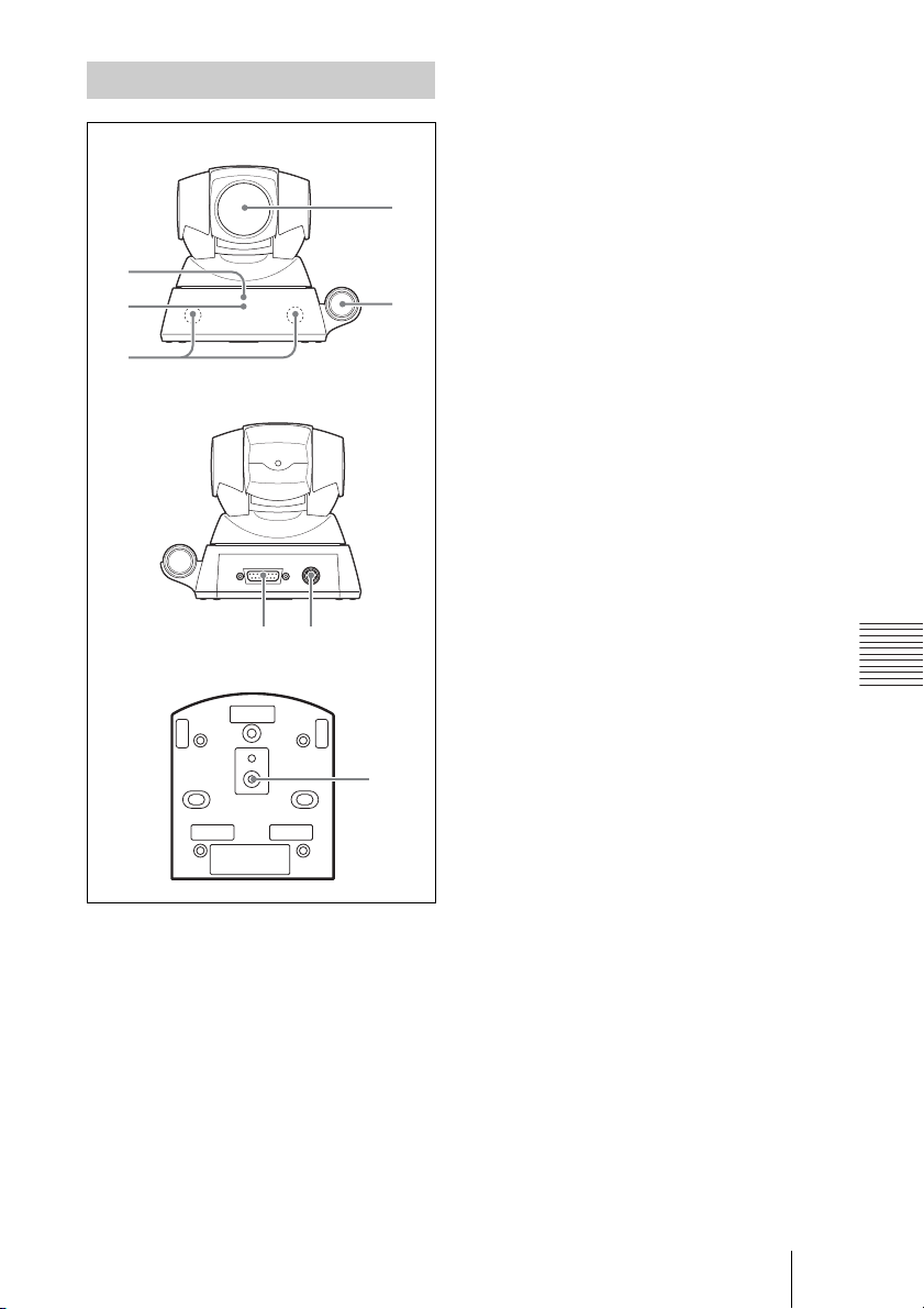
PCS-C1/C1P Camera Unit
Point the Remote Commander to the
sensor when operating this system.
Front
3
4
5
Rear
Bottom
TERMINAL VISCA OUT
67
e Infrared sensor
Receives the infrared wireless signal
from the optional PCS-DS150/DS150P
1
Document Stand. The received signal is
used as object input.
f TERMINAL connector
2
Connect to the CAMERA UNIT
connector on the Communication
Terminal.
g VISCA OUT connector
h Tripod hole
Use to attach the camera on a tripod.
Appendix
a Lens
b Microphone
c POWER indicator (green)
Lights when the power switch on the
Communication Terminal is set to on
and goes out when it is set to off or the
Communication Terminal is set to
standby mode.
d Remote sensor
8
83Location and Function of Parts and Controls
Page 84
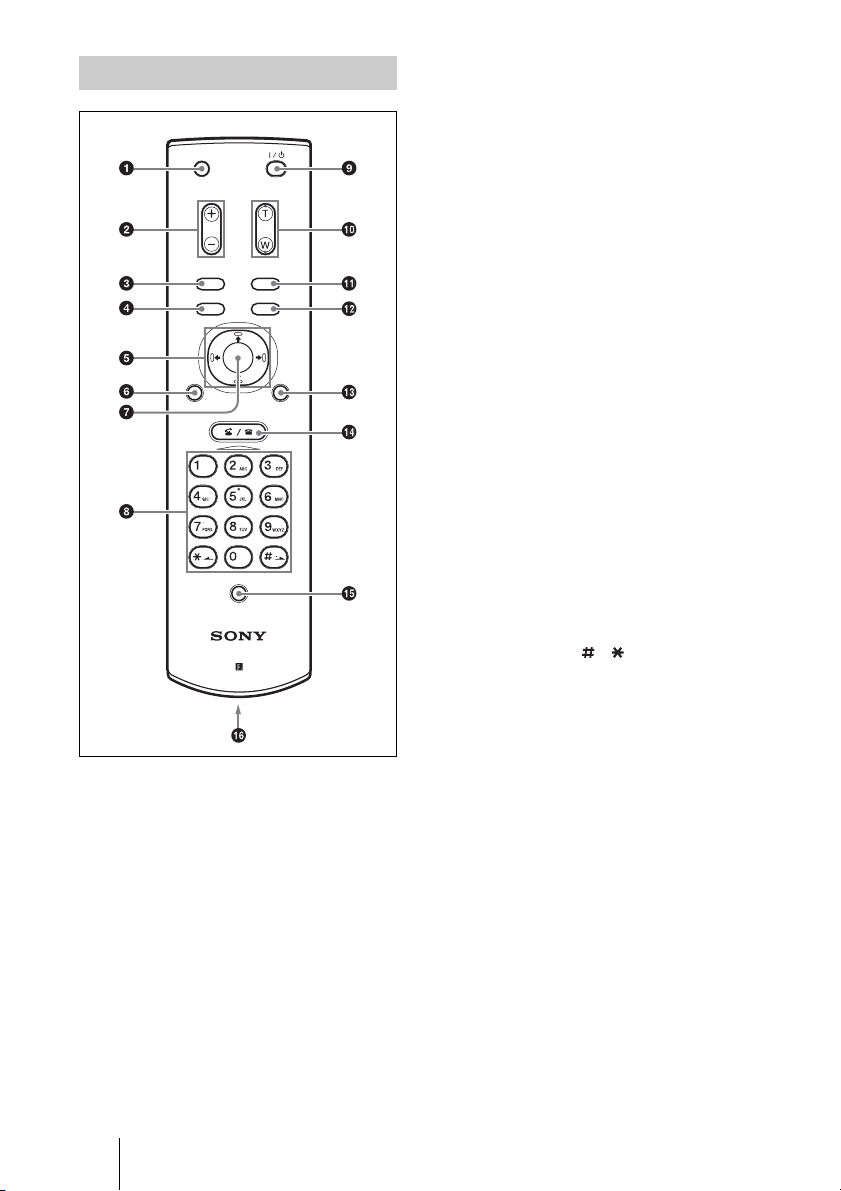
PCS-R1 Remote Commander
c DISPLAY (CLEAR) button
Deletes a line when used for character
input.
MIC
ON/OFF
VOLUME
ZOOM
VIDEOINPUT
DISPLAY
SELECT
CLEAR SYMBOL
PinP FAR/NEAR
BACK
ALPHA/
SPACE
NUM
PUSH
ENTER
RETURN MENU
CONNECT/
DISCONNECT
HELP
PCS-R1
d PinP (BACK SPACE) button
Displays a window picture when pressed
during communication.
Each time you press this button, the
location of the window picture changes.
Pressing the button displays the picture
in full screen while the Camera menu
opens.
When used for character input, deletes
the character you entered last.
e Arrow buttons (V/v/B/b)
Used to select the men u or make various
settings in the menu. Also used for
camera angle adjustment.
f RETURN button
Used to return to the previous layer in
the menu.
g PUSH ENTER button
Executes the selection or setting in the
menu and goes to the next layer.
h Number (0-9, , ) buttons
Used to enter the letters or numerals of a
telephone number, etc.
Used for focus, brightness and backlight
compensation adjustments.
You can set for a beep not to sound by
pressing the button on the Remote
Commander with the Audio Setup menu.
For the setting, see “Audio Setup Menu” on
page 26.
a MIC ON/OFF button
Cuts off the local sound to be sent to a
remote party. To restore the sound, press
the button again.
b VOLUME +/– button
Adjusts the volume of the sound
received from a remote party.
+: to increase the volume
–: to decrease the volume
84 Location and Function of Parts and Controls
i @/1 (power on/off) button
Sets the Communication Terminal to
standby mode when it is turned on.
Turns on the Communication Terminal
when it is in standby.
j ZOOM (T/W) buttons
Zooms in or out.
T: to enlarge the picture
W: to reduce the picture
k VIDEO INPUT SELECT
(SYMBOL) button
Selects the video input signal. Each time
you press the button, the input signal
switches.
Page 85

Used to enter a symbol for character
input.
l FAR/NEAR (ALPHA/NUM) button
Switches the picture on a local or remote
site.
Switches the input mode between
alphabets and numerals for character
input.
m MENU button
Used to display a menu.
n CONNECT/DISCONNECT ( /
) button
Used to connect or disconnect a remote
party for a conference.
o HELP button
Not used with this system.
p Battery compartment (rear)
Insert two size AA (R6) batteries.
Appendix
85Location and Function of Parts and Controls
Page 86

On Screen Messages
Check the following if a message appears on the monitor screen when
operating the Communication Terminal.
Note
The message list below does not contain the messages coming from the SCCP server.
For the messages from the SCCP server, consult the server administrator.
Message Meaning
Incorrect dialing setup. Make sure the selected entry is correctly registered.
Configuration error Communication error occurs.
Memory full The memory capacity of the “Memory Stick” is
Input title Input an index title.
Close this menu to connect line. Close the menu when starting a conference.
Operation disabled. —
Wrong password The password is not correct.
LAN configuration responses —
LAN configuration error.
(IP address)
LAN configuration error.
(Netmask)
LAN configuration error.
(MAC address)
LAN configuration error.
(DHCP error)
SNMP error SNMP is not set properly.
LAN configuration error (SNMP error) The setting of the SNMP is not proper.
LAN configuration error. The settings in the LAN Setup menu are not proper.
LAN setup error. The settings in the LAN Setup menu are not proper.
General error. —
Settings cannot be changed during
communication.
The LAN cannot be used. You cannot use the LAN connection.
Communication via LAN is not available.
Check LAN connection.
Communication via LAN is not available.
Check the LAN cable.
full.
Enter the correct password.
The IP address is not proper.
The netmask is not proper.
The MAC address is not proper.
The IP address and netmask cannot be obtained.
Change the setting after disconnecting the system.
The connection to a LAN cannot be made. Check
the LAN cable connection.
The connection to a LAN cannot be made. Check
the LAN cable.
86 On Screen Messages
Page 87
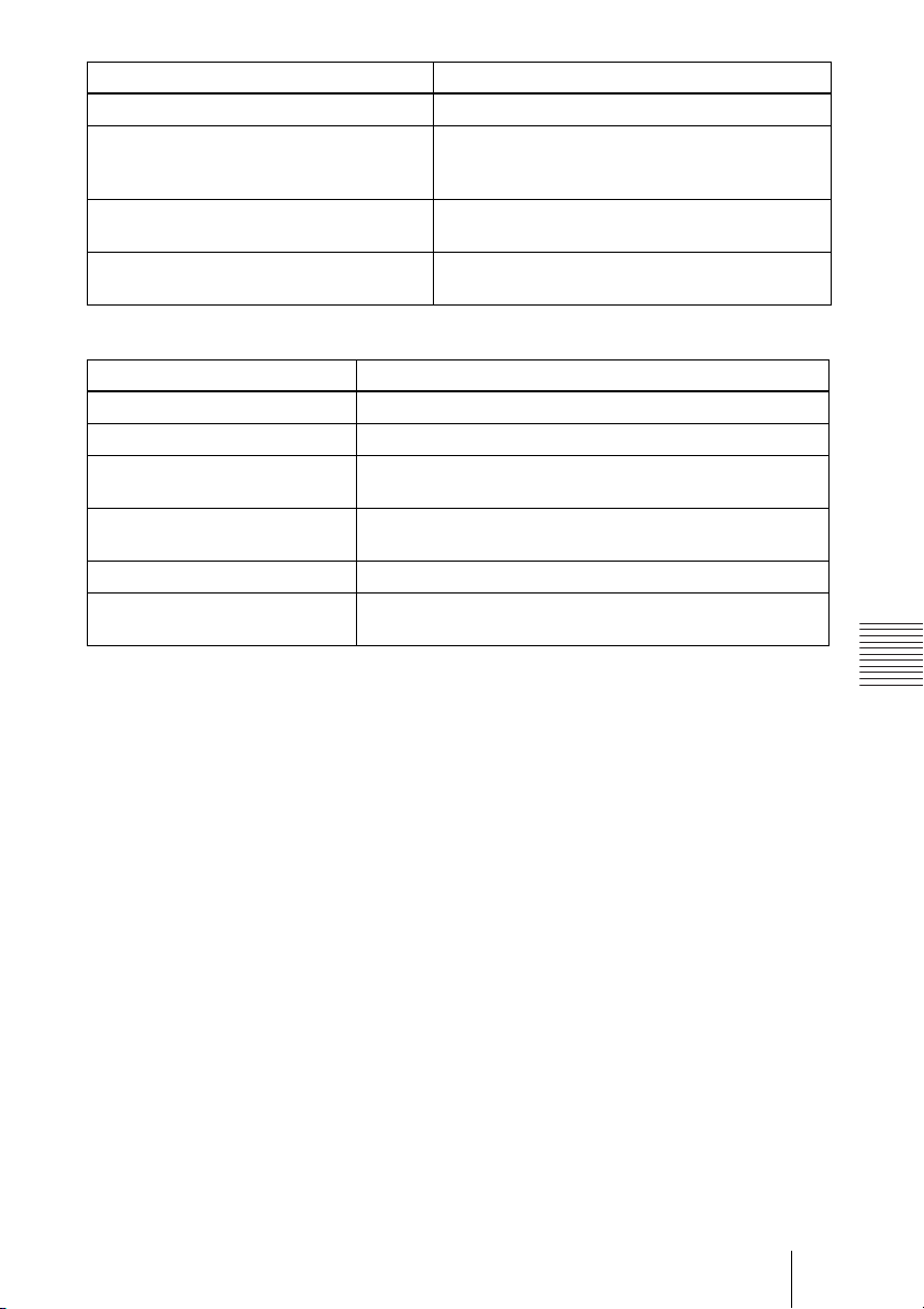
Message Meaning
An IP address is not obtained via DHCP. Check the DHCP setting.
Reference to DNS has failed. The LAN connection has failed as you entered the
A telephone number of a remote party has
not been entered.
The entered telephone number of a remote
party is not correct.
user name when using the domain name server.
Enter the IP address.
Enter the telephone number of the remote party.
Enter the correct telephone number of the remote
party.
The following messages indicate the state of the system. No action is required.
Message Meaning
Please wait. The data is being saved.
Installation completed. Installing the software is completed.
Preset 1 (–6) selected. The zoom and camera angle setting has been changed to that
Registered to Preset number 1 (–
6).
The system will be reset. The system will be reset.
The system will enter the standby
mode.
registered in Preset number 1 (–6).
The zoom and camera angle setting has been registered in
Preset number 1 (–6).
The system will enter the standby mode.
Appendix
87On Screen Messages
Page 88

Troubleshooting
If the Video Communication System does not function correctly, check the following.
Symptom Cause Solution
The power is not
turned on.
Three indicators on
the front of the
Communication
Terminal blink.
No sound or the
volume is very low.
Picture is blurred. Manual focus is selected but picture
No picture. The selected picture source is not
The power switch is not set to on. Set the power switch to on (
The batteries in the Remote
Commander are low or dead.
The fan inside the Terminal stops. Turn off the system immediately and
The volume of the System is too
low.
The volume of the TV monitor is
too low.
The microphone on the remote
party is turned off.
“Mic Select” is not set properly. Set up “Mic Select” properly in the
Audio input is not selected
properly.
The microphone or external
equipment is not connected or
installed correctly.
remains blurred.
When auto focus is selected, the
background is too bright, contrast is
too high, or the background or the
participants’ clothes contain fine
line patterns.
tuned on.
Video input is not selected properly. Select the video input with the
The selected picture source is not
correctly connected to the system.
Movement of the camera is
prevented.
15).
Replace the batteries with new ones
(page 12).
consult with Sony dealer.
Adjust the sound volume by pressing
the VOLUME +/– buttons on the
Remote Commander (page 18).
Adjust the volume of the TV monitor.
Ask the remote party to turn on the
microphone.
Audio Setup menu according to the
microphone to be used (page 26).
Set up “Input Select” in the Audio
Setup menu properly (page 26).
Check the connection and installation
(pages 72, 74 and 76).
Adjust the focus (page 62).
Select manual focus and adjust
manually (page 63).
Turn on the selected video equipment.
VIDEO INPUT SELECT button
(page 66).
Check the connections (page 77).
Turn off the Communication
Terminal, then turn it on again.
@) (page
88 Troubleshooting
Page 89
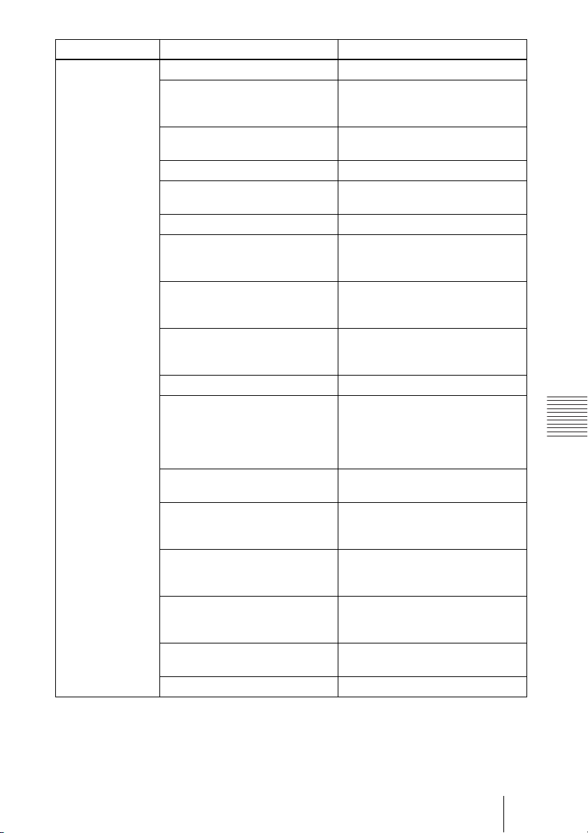
Symptom Cause Solution
No connection. Wrong number was dialed. Check the entered number.
Some of the system settings are not
correct.
The IP address and network mask
are not set correctly.
The LAN cable is disconnected. Connect correctly (page 11).
The LAN cable is connected to the
incorrect connector.
The LAN cable is down. Replace the cable with a new one.
The cable exclusively designed for
the ISDN connection is used for
LAN connection.
Incorrect type of cable (cross or
straight cable) is used for the LAN
connection.
If you repeat plugging/unplugging
or turning on/off, you may not
connect to the network for a while.
LAN connection timeout. Try again later.
Packet for videoconferencing is not
acceptable under the current LAN
environment.
The remote terminal is not turned
on.
It takes a long time for the remote
party to be able to answer from the
standby mode.
The remote party is in
communication with another party.
Answering the call is not permitted
by the remote terminal as it is
operating for setups, etc.
There is some problem with the
remote terminal.
A message appears on the screen. See “On Screen Messages” (page 86).
Set the system settings correctly
referring to “Registering Local
Information” (page 23).
Ask the system administrator to set
them correctly (page 30).
Connect correctly (page 11).
Use the cable for LAN connection.
Use the correct type of cable.
Turn off the power of the system and
wait for a few minutes before turning
it on again.
Consult with the system administrator
so that the packet for
videoconferencing becomes
acceptable under your LAN
environment.
Ask the remote party to turn on the
terminal.
Ask the remote party to cancel the
standby mode.
Call the remote party after they end
the communication with another
party.
Ask the remote party to permit
answering a call.
Try to dial the number of another
terminal.
Appendix
89Troubleshooting
Page 90

Specifications
5.3 Kbps, 6.3 Kbps (G.723.1
compliant with ITU-T
Recommendation) (when using
LAN)
PCSA-SC1 SCCP Software
Dimensions 50 × 2.8 × 21.5 mm (w/h/d) (2 ×
Mass Approx. 4 g (0.1 oz)
Supplied accessories
1
/8 × 7/8 inches)
CD-ROM (1)
Quick Start Guide (1)
Serial Number seal (1)
PCS-P1/P1P Communication
Terminal
Note
The following specifications apply when the
PCSA-SC1 SCCP Software is installed in the
PCS-P1/P1P Communication Terminal.
Motion picture
Operating bandwidth
Coding H.261/H.263/H.264
Picture elements
Color system NTSC
Sound
Bandwidth 7 kHz (G.722 compliant with ITU-
Transmission rate
64 Kbps to 1920 Kbps (standard,
LAN connection)
CIF: 352 pixels × 288 lines
QCIF: 176 pixels × 144 lines
(PAL system connection is
possible.)
T Recommendation)
3.4 kHz (G.711/G.723.1/G.728/
G.729a compliant with ITU-T
Recommendation)
56 Kbps, 64 Kbps (G.711
compliant with ITU-T
Recommendation)
48 Kbps, 56 Kbps, 64 K bps (G.722
compliant with ITU-T
Recommendation)
16 Kbps (G.728 compliant with
ITU-T Recommendation)
8 Kbps (G.729a compliant with
ITU-T Recommendation)
(when using LAN)
Network
Multiplexing
Interface LAN (standard), 64 Kbps to 1920
LAN protocol supported
Video, audio, data
Kbps
HTTP
FTP
Telnet
RTP
TCP/UDP
TFTP
General
Power requirements
Power consumption
Operating temperature
Operating humidity
Storage temperature
Storage humidity
Dimensions 258 × 54 × 171 mm (w/h/d)
Mass Approx. 1.3 kg (2 lb 14 oz)
Supplied accessories
19.5 V
3.5 A
5°C to 35°C (41°F to 94°F)
20% to 80%
–20°C to +60°C (–4°F to +140°F)
20% to 80% (no condensation)
1
/4 × 2 1/4 × 6 3/4 inches) (not
(10
including the projected
Remote Commander PCS-R1 (1)
Size AA (R6) batteries for Remote
Commander (2)
IR repeater (2)
Camera cable (0.25 m, 0.8 ft) (1)
S-video connecting cable (1.5 m,
4.9 ft) (1)
Audio connecting cable (1 m, 3.3
ft) (1)
AC adaptor PCS-AC195 (1)
Power cord (1)
21-pin adaptor (1) (PCS-P1P only)
Velcro (3 for the Camera Unit, 2
for the Communication
Terminal)
CD-ROM (1)
Operation guide (1)
Warranty booklet (1)
parts)
90 Specifications
Page 91

PCS-C1/C1P Camera Unit
PCS-AC195 AC Adaptor
Video signal
NTSC color, EIA standards (PCS-
C1)
PAL color, CCIR standards (PCS-
C1P)
Image device
1/4 type CCD (Charge Coupled
Device)
Approx. 410 000 p ixels (Effective:
approx. 380 000 pixels) (PCSC1)
Approx. 470 000 p ixels (Effective:
approx. 440 000 pixels) (PCSC1P)
Lens f = 3.1 to 31 mm, F 1.8 to 2.9,
Horizontal angle 6.6° to 65°
Focal distance
100 (WIDE) to 600 (TELE) mm
Minimum illumination
3.5 lux at F 1.8/50 IRE
Illumination range
3.5 lux to 100 000 lux
Horizontal resolution
470 TV lines (PCS-C1)
450 TV lines (PCS-C1P)
Pan/tilt action
Horizontal ±100°
Vertical ±25°
Dimensions 147 × 130 × 138 mm (w/h/d) (5
1
/8 × 5 1/2 inches) (not
× 5
including the projected parts)
Mass Approx. 1.1 kg (2 lb 7 oz)
Power requirements
100 to 240V AC, 50/60 Hz, 1.3 A
to 0.6 A
Output 19.5 V, 4.1A
Operating temperature
5°C to 35°C (41°F to 94°F)
Operating humidity
20% to 80%
Storage temperature
–20°C to +60°C (–4°F to +140°F)
Storage humidity
20% to 80% (no condensation)
Dimensions 63 × 31 × 140 mm (w/h/d) (2
1
/4 × 5 5/8 inches)
1
Mass Approx. 410 g (14 oz)
Design and specifications are subject to change
without notice.
7
/8
1
/2 ×
Appendix
Microphone
Frequency range
Directional characteristic
18 kHz
Narrow-angle directional
PCS-R1 Remote Commander
Signal format
Control DC 3V using two size AA (R6)
Dimensions 50 × 24 × 197 mm (w/h/d) (2 ×
Mass Approx. 140 g (4 oz) (including
Infrared SIRCS
batteries
31
/32 × 7 7/8 inches) (not including
the projected parts)
batteries)
91Specifications
Page 92

Acceptable RGB Output Signals
PCS-P1/P1P Communication Terminal (RGB OUT)
Picture element Signal format fH (kHz) fV (Hz) Dot clock
(MHz)
1024 × 768 XGA VESA 60 Hz 48.363 60.004 65 H-neg V-neg
Sync
92 Specifications
Page 93
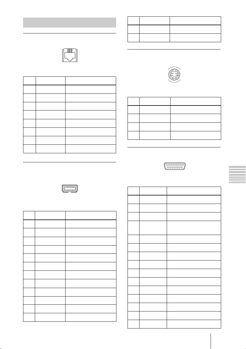
Pin Assignment
100BASE-TX/10BASE-T jack
18
Pin Signal Description
13 19.5V 19.5V
14 GND Ground
VIDEO OUT MONITOR MAIN/SUB,
VIDEO IN AUX 1/AUX 2 connectors
Modular jack
Pin Signal Description
1TPOP Transmit+
2TPON Transmit–
3 TPIP Receive+
4NC —
5NC —
6 TPIN Receive–
7NC —
8NC —
ISDN UNIT connector
(Not used with this system)
214
113
USB connector
Pin Signal Description
1 GND Ground
2 19.5V 19.5V
3 DCLK+ Clock+
4 DCLK– Clock–
5 DR+ Receive data+
6 DR– Receive data–
7 FS+ Frame sync+
8 FS– Frame sync–
9 DX+ Transmit data+
10 DX– Transmit data–
11 RX Serial receive data
12 TX Serial transmit data
4
3
2
1
Mini-DIN 4-pin connector
Pin Signal Description
1 GND Analog Ground
2 GND Analog Ground
3 Y Brightness Signal
4 C Chrominance Signal
CAMERA UNIT connector
81
15 9
D-sub 15-pin connector (female)
Pin Signal Description
1 Y Brightness signal
2 Y.GND Brightness signal ground
3 C Chrominance signal
4 C.GND Chrominance signal
ground
5 Video Video signal
6 Video.GND Video signal Ground
7 TXD Transmit data
8 RXD Receive data
9 19.5 V 19.5 V
10 MIC+ Microphone+
11 MIC– Microphone–
12 SIRCS Remote control data
13 DTR Data terminal ready
14 STANDBY Standby
15 GND Ground
Appendix
93Specifications
Page 94
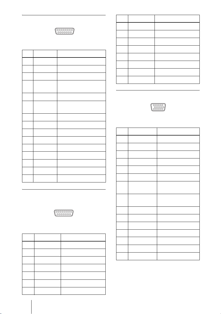
TERMINAL connector
81
15 9
D-sub 15-pin connector (female)
Pin Signal Description
1 Y Brightness signal
2 Y.GND Brightness signal ground
3 C Chrominance signal
4 C.GND Chrominance signal
ground
5 Video Video signal
6Video.GNDVideo signal Ground
7RXD Receive data
8 TXD Transmit data
9 19.5 V 19.5 V
10 MIC+ Microphone+
11 MIC– Microphone–
12 SIRCS Remote control data
13 DTR Data terminal ready
14 STANDBY Standby
15 GND Ground
DSB connector
(Not used with this system)
18
9 15
D-sub 15-pin (male)
Pin Signal Description
1 Video Video signal
2 Video.GND Video signal ground
3 LINE A+ Line audio+
4 LINE A– Line audio–
5 MIC+ Microphone+
6 MIC– Microphone–
7 TD+ Transmit data+
Pin Signal Description
8 TD– Transmit data–
9 19.5V 19.5V
10 NC –
11 AGND Analog ground
12 NC –
13 RD+ Receive data+
14 RD– Receive data–
15 GND Ground
RGB OUT connector
51
10 6
15 11
Mini D-sub 15-pin (female)
Pin Signal Description
1RED R (red)
2 GREEN G (green)
3BLUE B (blue)
4NC –
5 GND Ground
6 RED.GND R (red) signal ground
7 GREEN.GND G (green) signal
ground
8 BLUE.GND B (blue) signal
ground
9NC –
10 SYNC.GND Sync signal ground
11 NC –
12 NC –
13 HSYNC Horizontal sync
14 VSYNC Vertical sync
15 NC –
94 Specifications
Page 95
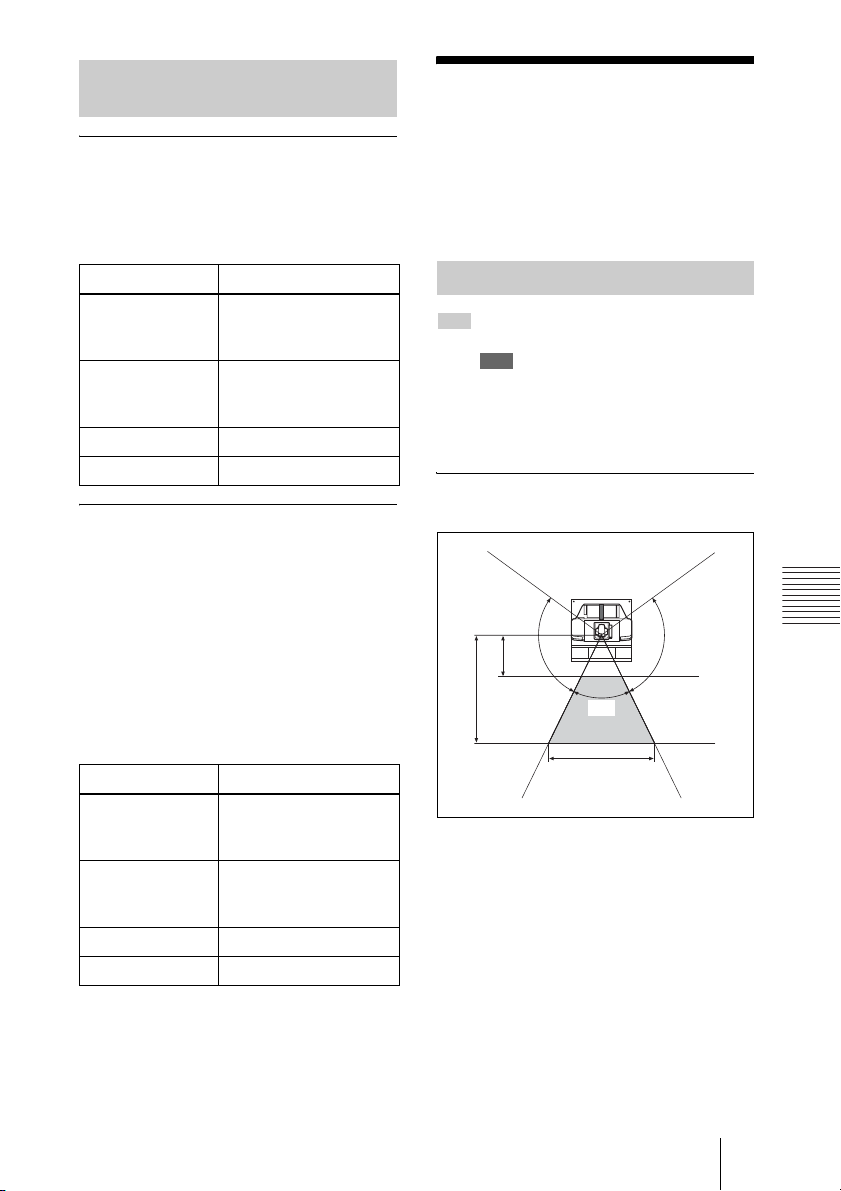
List of Port Numbers Used on
the PCSA-SC1
When connecting one-to-one
(Default)
When “Port Number Used” is set to
“Default” in the LAN Setup menu, the
PCSA-SC1 uses the following port numbers.
Videoconferencing
Room Layout
Be sure to position camera and microphone
appropriately in your videoconferencing
room.
Signal Port number
TCP connection to
Primary
CallManager
TCP connection to
Secondary
CallManager
Audio RTP 49152
Video RTP 49154
2253
2254
When connecting one-to-one
(Custom: TCP Port Number 3000
and UDP Port Number 3100)
When “Port Number Used” is set to
“Custom” in the LAN Setup menu, the
PCSA-SC1 uses the port numbers defined
by the values entered in “TCP Port Number”
and “UDP Port Number”.
For example, when “TCP Port Number” is
set to “3000” and “UDP Port Number” is set
to “3100”, the PCSA-SC1 uses the following
port numbers.
Signal Port number
TCP connection to
Primary
CallManager
TCP connection to
Secondary
CallManager
Audio RTP 3100
Video RTP 3102
3000
3001
Camera Range
represents the shooting area of the
camera when the zoom has been extended
fully. indicates the shooting area of the
camera when the left/right angling function
is fully utilized. Use the measurements
below as a guide for the layout of your
videoconferencing room.
Top view (horizontal range at
maximum zoom-out)
1.5 m
(4.92 ft)
100˚
4 m
(13.12 ft)
65˚
5.1 m (16.73 ft)
100˚
Appendix
95Videoconferencing Room Layout
Page 96
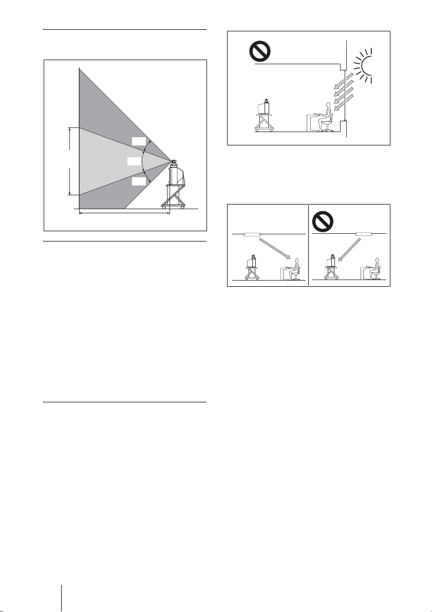
Side view (vertical range at
maximum zoom-out)
25˚
3.1 m
(8.41 ft)
42˚
25˚
4 m (13.12 ft)
Layout Considerations
• Avoid having large, moving objects,
especially people, behind the participants,
as the quality of the picture transmitted to
the remote party will deteriorate.
• Do not seat participants in front of a wall
with fine stripe patterns.
• Choose a room where echo will not occur.
• Do not install the system near noise
sources such as air conditioners or copy
machines.
• Avoid placing the system in a room where
there are the speakers used for an in-house
broadcasting system.
Adjust room lighting so that it falls on the
participants. Avoid direct light on the
monitor screen. Light intensity on faces
should be about 300 lux or more.
If an inverter type or brightness-adjustable
type of fluorescent lamp is used, the
sensitivity of the Remote Commander may
deteriorate.
Lighting Considerations
Do not point the camera toward a window
where sunlight comes in as back lighting
may decrease the contrast. If it is necessary,
cover the window with a thick curtain.
96 Videoconferencing Room Layout
Page 97
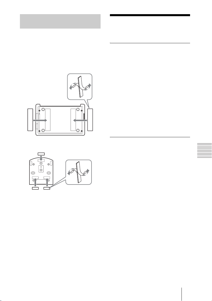
Installing the Communication
Terminal and Camera
You can fix the Communication Terminal or
the Camera to your chosen place of
installation using the supplied Velcro.
1 Stick the supplied Velcro to the
bottom of the Communication
Terminal or Camera.
3
3
3
3
About a “Memory
Stick”
What is “Memory Stick”?
“Memory Stick” is a new compact, portable
and versatile IC (Integrated Circuit)
recording medium with a data capacity that
exceeds a floppy disk. “Memory Stick” is
specially designed for exchanging and
sharing digital data among “Memory Stick”
compatible products. Because it is
removable, “Memory Stick” can also be
used for external data storage.
“Memory Stick” is available in two sizes:
standard size and compact “Memory Stick
Duo” size. Once attached to a Memory Stick
Duo adapter, “Memory Stick Duo” turns to
the same size as standard “Memory Stick”
and thus can be used with products
compliant with standard “Memory Stick.”
Bottom of the Communication
Terminal
Bottom of the Camera Unit
2 Stick another piece of Velcro to the
installation place.
3 Install the Communication Terminal
or the Camera on the installation place
by securing the two pieces of Velcro.
Types of “Memory Stick”
There are five types of “Memory Stick”
depending on various uses.
• “Memory Stick PRO”
Equipped with MagicGate copyright
protection technology, designed for use
only with equipment compatible with
“Memory Stick PRO”.
• “Memory Stick-R”
Data stored in this type of “Memory Stick”
is not overwritten. It can be used only with
equipment compatible with “Memory
Stick-R”. Data that requires MagicGate
copyright protection technology cannot be
stored on this type.
• “Memory Stick”
Any type of data except copyrightprotected data that requires MagicGate
copyright protection technology can be
stored.
• “MagicGate Memory Stick”
Equipped with the MagicGate copyright
protection technology.
• “Memory Stick-ROM”
Stores pre-recorded, read-only data.
Recording or erasing data cannot be done
with this type.
Appendix
97About a “Memory Stick”
Page 98
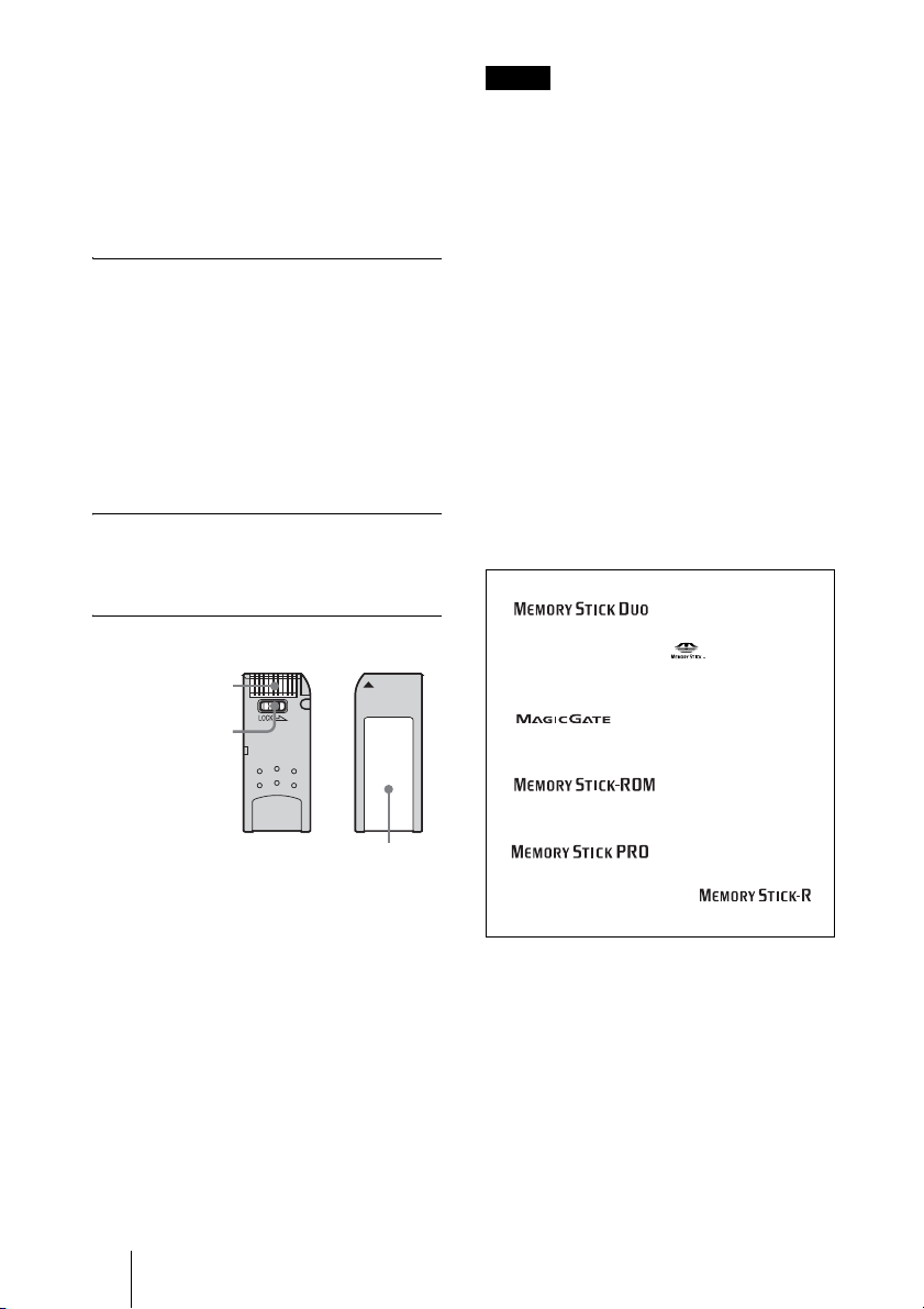
• “Memory Stick” (with memory select
function)
Equipped with multiple memories (128
MB). You can select the memory to use
with the memory select switch on the back
of the “Memory Stick”. You cannot use
different memories simultaneously or
continuously.
Notes on “Memory Stick Duo”
• Be sure to attach “Memory Stick Duo” to
the adapter with the correct orientation.
• Be sure to insert the Memory Stick Duo
adapter with the correct orientation.
Otherwise, the unit may be damaged.
• Do not insert the Memory Stick Duo
adapter without “Memory Stick Duo”
attached. Doing so may result in
malfunction of the unit.
What is MagicGate ?
MagicGate is copyright protection
technology that uses encryption technology.
Before using a “Memory Stick”
Terminal
Write-protect tab
Labeling position
• When you set the “Memory Stick” writeprotect tab to “LOCK,” data cannot be
recorded, edited, or erased.
• Use a sharp object, such as a ballpoint pen,
to move the “Memory Stick Duo” erasure
prevention switch.
• Data may be damaged if:
– You remove the “Memory Stick” or turn
off the unit while it is reading or
writing data.
– You use the “Memory Stick” in a
location subject to the effects of static
electricity or electric noise.
Notes
• Do not attach any other material than the
supplied label onto the label space.
• Attach the label so that it does not stick out
beyond the labeling position.
• Do not write forcefully on the “Memory
Stick Duo” memo area.
• Carry and store the “Memory Stick” in its
case.
• Prevent metallic objects or your finger from
coming into contact with the metal parts of
the connecting section.
• Do not strike, bend, or drop the “Memory
Stick.”
• Do not disassemble or modify the “Memory
Stick.”
• Do not allow the “Memory Stick” to get wet.
• Do not use or store the “Memory Stick” in a
location that is:
– extremely hot, such as in a car parked in
the sun.
– under direct sunlight.
– very humid or subject to corrosive
substances.
• “Memory Stick Duo” and
are trademarks of Sony
Corporation.
• “Memory Stick” and are trademarks
of Sony Corporation.
• “MagicGate Memory Stick” and
are trademarks of Sony
Corporation.
• “Memory Stick-ROM” and
are trademarks of
Sony Corporation.
• “Memory Stick PRO” and
are trademarks of
Sony Corporation.
• “Memory Stick R” and
are trademarks of Sony Corporation.
98 About a “Memory Stick”
Page 99

Glossary
CIF
An abbreviation for Common Intermediate
Format. This format allows communication
between different color systems (NTSC and
PAL).
352 pixels × 288 lines
Codec
An abbreviation for Coder-Decoder. An
integrated device of a coder that converts an
analog audio/video signal to a digital data
stream and compresses it, and a decoder for
expanding to restore the original analog
signal.
G.723.1
Audio encoding/decoding format
recommended by the ITU-T. A phone
bandwidth audio signal is converted to a
digital signal with a data rate of 5.3 Kbps or
6.3 Kbps.
G.728
Audio encoding/decoding format
recommended by the ITU-T. A phone
bandwidth audio signal is converted to a
digital signal with a data rate of 16 Kbps.
G.729
Audio encoding/decoding format
recommended by the ITU-T. A phone
bandwidth audio signal is converted to a
digital signal with the data rate of 8 Kbps.
DHCP
An abbreviation for Dynamic Host
Configuration Protocol. Manages IP
addresses in the network.
DNS
An abbreviation for Domain Name System.
Defines the domain name system.
Echo Canceler
Device to eliminate echo that occurs when
transmitting audio.
Frame rate
The number of frames which can be
encoded/decoded in one second.
G.711
Audio encoding/decoding format
recommended by the ITU-T. A phone
bandwidth audio signal is converted to a
digital signal with a data rate of 64 Kbps. It
can be transmitted with a data rate of 56
Kbps.
G.722
Audio encoding/decoding format
recommended by the ITU-T. A 7-kHz
bandwidth audio signal is converted to a
digital signal with a data rate of 48 Kbps, 56
Kbps or 64 Kbps.
H.261
Video codec for audio/visual services as p ×
64 Kbps. Videoconferencing standard that
defines a video coding algorithm, picture
format and error correcting technology for
communication between different
manufacturers’ video codecs.
H.263
A video coding algorithm based on the
H.261 standard. This format enables
communication via a lower bit rate.
H.264
A video coding algorithm newly
standardized by the ITU-T in May 2003.
This format realizes high-quality picture via
a lower bit rate. It provides an equal picture
quality via half as low bit rate as the H.263
format. The H.264 format is also called as
MPEG4 Advanced Video Coding (AVC).
ITU-T
An abbreviation for International
Telecommunication Union,
Telecommunications.
Lip synchronization
A function that synchronizes sound with
motion. Sound processing is much faster
than motion processing, thus sound and
motion sometimes get out of step with each
other.
Appendix
99Glossary
Page 100

P in P
An abbreviation for “Picture in Picture.”
This is a function which allows you to
monitor your own party on a small window
on your TV monitor.
SNMP
An abbreviation for Simple Network
Management Protocol. This protocol is for
management information between the
management station and the managed
terminals.
SPID
An abbreviation for Service Profile ID.
TOS
Inputting the information data in the TOS
field of the IP address allows the
communication system to judge the packet
transmission priority, etc. It also enables
change of path according to the types of
service (Delay or Size).
100 Glossary
 Loading...