

Sony PCS-1500, PCS-1500P Operating Instructions Manual

PCS-1500/1500P
3-867-208-15(1)
Compact
Conference P ac ka ge
Operating Instructions
Before operating the unit, please read this manual
thoroughly and retain it for future reference.
PCS-1500/1500P
1999 Sony Corporation

Owner’s Record
The model and the serial numbers are
located at the bottom. Record the
serial number in the space provided
below. Refer to these numbers
whenever you call upon your Sony
dealer regarding this product.
Model No. PCS-1500/1500P
Serial No. ______________
WARNING
To prevent fire or shock
hazard, do not expose the
unit to rain or moisture.
This equipment has been tested and
found to comply with the limits for a
Class A digital device, pursuant to
Part 15 of the FCC Rules. These limits
are designed to provide reasonable
protection against harmful interference
when the equipment is operated in a
commercial environment. This
equipment generates, uses and can
radiate radio frequency energy and, if
not installed and used in accordance
with the instruction manual, may
cause harmful interference to radio
communications. Operation of this
equipment in a residential area is
likely to cause harmful interference in
which case the user will be required to
correct the interference at his own
expense.
To avoid electrical shock,
do not open the cabinet.
Refer servicing to qualified
personnel only.
For the customers in the USA
This device complies with Part 15 of
the FCC Rules.
Operation is subject to the following
two conditions: (1) This device may
not cause harmful interference, and (2)
this device must accept any
interference received, including
interference that may cause undesired
operation.
2
You are cautioned that any changes or
modifications not expressly approved
in this manual could void your
authority to operate this equipment.
The shielded interface cable
recommended in this manual must be
used with this equipment in order to
comply with the limits for a
computing device pursuant to Subpart
B of Part 15 of FCC Rules.

IMPORTANT INSTRUCTION TO
USERS
1. This equipment complies with Part
68 of the FCC Rules. On the bottom
of this equipment is a label that
contains, among other information,
the FCC registration number for this
equipment. If requested, this
information must be provided to the
telephone company.
2. If this terminal equipment causes
harm to the telephone network, the
telephone company will notify you
in advance that temporary
discontinuance of service may be
required. But if advance notice is
not practical, the telephone
company will notify the customer as
soon as possible. Also, you will be
advised of your right to file a
complaint with the FCC if you
believe it is necessary.
3. The telephone company may make
changes in its facilities, equipment,
operations or procedures that could
affect the operation of the
equipment. If this happens the
telephone company will provide
advance notice in order for you to
make necessary modifications to
maintain uninterrupted service.
4. If trouble is experienced with this
equipment for repair or warranty
information, please contact Sony
Business Information Center 1800-686-7669. If the equipment is
causing harm to the telephone
network, the telephone company
may request that you disconnect this
equipment until the problem is
resolved.
5. This equipment cannot be used on
public coin phone service provided
by the telephone company.
Connection to party line service is
subject to state tariffs.
For the Customers in the United
Kingdom
APPROVAL NOTICE
Compact processor PCS-P150P is
approved for connection to PSTN
using basic rate access interface
compatible with CCITT I.420 (ISDN).
The BABT approval number for PCSP150P is BABT/609669.
This manual focuses on using
ISDN lines to conduct a
videoconference, but it also covers
non-ISDN lines. If you use ISDN
lines, consult your Sony dealer for
more information.
• The ISDN service may not be
available in some areas.
Voor de klanten in Nederland
Bij dit product zijn batterijen geleverd.
Wanneer deze leeg zijn, moet u ze niet
weggooien maar inleveren als KCA.
3

For the customers in Canada
This Class A digital apparatus
complies with Canadian ICES-003.
NOTICE: The Industry Canada label
identifies certified equipment. This
certification means that the equipment
meets certain telecommunications
network protective, operational and
safety requirements as prescribed in
the appropriate Terminal Equipment
Technical Requirements document (s).
The Department does not guarantee
the equipment will operate to the
user’s satisfaction.
Before installing this equipment, users
should ensure that it is permissible to
be connected to the facilities of the
local telecommunications company.
The equipment must also be installed
using an acceptable method of
connection. The customer should be
aware that compliance with the above
conditions may not prevent
degradation of service in some
situations.
Users should ensure for their own
protection that the electrical ground
connections of the power utility,
telephone lines and internal metallic
water pipe system, if present, are
connected together. This precaution
may be particularly important in rural
areas.
Caution: Users should not attempt to
make such connections themselves,
but should contact the appropriate
electric inspection authority, or
electrician, as appropriate.
Repairs to certified equipment should
be made by an authorized Canadian
maintenance facility designated by the
supplier. Any repairs or alterations
made by the user to this equipment, or
equipment malfunctions, may give the
telecommunications company cause to
request the user to disconnect the
equipment.
4

Table of Contents
Precautions ...................................................................... 9
Chapter 1
Preparation
Features.......................................................................... 11
System Configuration ................................................... 13
Basic System Equipment ..............................................13
Options..........................................................................14
Basic System Connection ............................................ 16
Preparing the System.................................................... 17
Inserting Batteries into the Remote Commander..........17
Preparing the TV Monitor ............................................ 18
Installing the Compact Processor .................................19
Turning the System On/Off ........................................... 20
Turning On ...................................................................20
Setting the System (Compact Conference Package)
to be on Standby......................................................22
On the Guide Menu ......................................................23
On the Version And Option Indications .......................23
Turning Off...................................................................24
Chapter 2
Basic Operation During a Meeting
Calling a Remote Party ................................................. 25
Calling an Unregistered Remote Party .........................25
On Items in the Dial Setup Menu .................................30
Calling a Registered Remote Party...............................32
Receiving a Call ............................................................. 34
Setting the Answer Mode .............................................34
Answering Calls in Auto Answer Mode.......................35
Answering Calls in Manual Answer Mode ..................36
Checking the Connection Status ................................. 37
Adjusting the Sound ..................................................... 39
Adjusting the Volume...................................................39
Muting Local Conversations – Mute Function.............39
Synchronizing Voice and Motion
– Lip Synchronization.............................................39
(Continued)
Table of Contents 5

Table of Contents
Adjusting the Camera ................................................... 42
Selecting the Picture and Sound ................................. 51
Monitoring Yourself in the Inset Window.................... 53
Sending Still Pictures.................................................... 54
Ending a Meeting........................................................... 55
Chapter 3
Advanced Operation
Connecting With an MCU.............................................. 56
Voice Meeting ................................................................ 59
On the Echo canceler ....................................................41
Adjusting the Camera Angle and Zoom .......................43
Adjusting Focus and Brightness ...................................43
Presetting Angle, Zoom, Focus, and Brightness
Settings....................................................................47
Tracking a Subject Automatically
— Automatic Target Tracking Function.................48
Sending Still Pictures Continuously .............................54
Sending One Still Picture .............................................54
Chapter 4
Registration and Setup
Registering Local Information...................................... 60
Setting Up the ISDN Configuration Menus..................60
Setting Up the LAN Items ............................................64
SPID Registration for Customers in the USA ............. 68
Registering a Remote Party.......................................... 75
Making an Entry for Connecting With the ISDN Line.75
Making an Entry for Connecting on a LAN .................78
Deleting Registered Remote Parties .............................80
Duplicating the Setting of the Dial List Menu..............81
Notes on Registration ...................................................81
Entering Characters ......................................................82
Setting Up the System .................................................. 83
Displaying the Menu ....................................................83
Menu Settings ...............................................................84
6 Table of Contents

Chapter 5
Meetings With Optional Equipment
Installing the Optional Board ....................................... 88
Using Three ISDN Lines ..............................................89
Using the V.35 Interface...............................................89
Using a LAN.................................................................90
Upgrading the Software ................................................ 91
Using Optional Microphones........................................ 93
Using the External Equipment ..................................... 94
Connecting External Video Equipment for Input.........94
Connecting External Equipment for Output .................95
Holding a T.120 Data Conference ................................ 96
Connecting With a PC ..................................................96
Setting Up the Compact Processor ...............................97
Setting Up NetMeeting ................................................. 97
Connecting with NetMeeting........................................98
Suspending the T.120 Data Conference Temporarily ..99
Chapter 6
Meetings With the Upgrade Kit
Features........................................................................ 100
Preparing a Point to Multi-Point Meeting .................. 101
Setting Up the MCU SETUP Menu ...........................101
Starting a Point to Multi-Point Meeting ..................... 103
Calling Remote Parties ...............................................103
Receiving Calls...........................................................104
Notes on Point to Multi-Point Meetings.....................104
Operating Chair Controls............................................ 105
Switching the Broadcast Mode...................................105
Selecting the Picture to be Broadcast .........................105
Verifying the Picture Shot by the Local Camera........106
Receiving the Broadcast Request ...............................106
Checking the Connection Status ............................... 107
Ending a Point to Multi-Point Meeting ....................... 108
Notes on Secondary Terminals .................................. 109
The Attribute ................................................................ 110
(Continued)
Table of Contents 7

Table of Contents
Appendix
Location and Function of Parts and Controls .......... 112
On Screen Messages .................................................. 122
Troubleshooting .......................................................... 125
Specifications .............................................................. 127
Videomeeting Room Layout ....................................... 134
Glossary ....................................................................... 137
Index ............................................................................. 139
Compact Processor ..................................................... 112
The Indications on the Screen.....................................117
Remote Commander ...................................................118
Compact Processor ..................................................... 127
Remote Commander (PCS-R150) ..............................129
AC Adaptor (PCS-AC15) ...........................................129
Pin Assignment ...........................................................130
Pin Assignment on Optional Board Connectors .........131
Camera Range.............................................................134
8 Table of Contents

Precautions
On Safety
Power supply
• Before operating the Compact Conference Package, make
sure the operating voltage of the unit is identical with that of
your local power supply. The Remote Commander operates
on two size AA (R6) alkaline batteries.
• Do not unnaturally bend or crimp the power cord, and do not
place heavy objects on it. Damage to the cord may result in
fire or electric shock.
• To remove the power cord from an AC outlet, pull out the
plug. (Do not pull out the cord itself.)
Do not disassemble the system
Do not open or disassemble the cabinets of the system. Electric
shock may result if you touch the inside of the cabinets.
Do not put foreign objects into the system
Avoid having metallic or flammable object, liquid, or foreign
matters fall into the cabinets of the system. Otherwise a
malfunction may result.
In case of trouble
In case of trouble such as smoke, odd smell, or noise, turn off
all units of the system. Disconnect all the power cords and
connecting cords. Then contact the place of purchase or an
authorized Sony representative.
ISDN
Never install telephone wiring during a lightning storm.
Never install telephone jacks in wet locations unless the jack is
specifically designed for wet locations.
Never touch uninsulated telephone wires or terminals unless
the telephone line has been disconnected at the network
interface.
Use caution when installing or modifying telephone lines.
Avoid using a telephone (other than a cordless type) during an
electrical storm. There may be a remote risk of electric shock
from lightning.
Do not use the telephone to report a gas leak in the vicinity of
the leak.
Precautions 9

Precautions
On Handling
Installation/storage
Do not expose the system to:
• Extremely low or high temperatures.
• Damp or dusty room.
• Strong vibration.
• Near devices which generate strong magnetic fields.
• Near devices (such as radios) which transmit strong radio
wave.
• Noisy place.
Cleaning
Wipe the cabinets and panels with a dry and soft cloth. If the
stain is serious, slightly moisten the cloth with mild detergent.
Afterward, use a dry cloth to wipe it. Do not use solvents such
as thinner, benzine, alcohol, as they may damage the finish of
the cabinets.
10 Precautions

Features
Chapter 1
Chapter 1
Preparation
The PCS-1500/1500P Compact Conference Package can
connect a remote party via an ISDN (Integrated Services
Digital Network) line1). It sends and receives images and
sound, allowing you to have virtual face-to-face meetings with
people in other cities or countries.
The system accommodates up to three participants in one
location. However, you can add the optional PCS-A300
Microphones for additional participants.
If you upgrade the Compact Conference Package using the
PCS-UC150 Upgrade Kit, you can use the Compact
Conference Package as the MCU (Multipoint Control Unit) to
hold a point to multi-point meeting among four terminals.
1) You can install an optional interface board for connection
with V.35 interface, with 6B channels, or on a LAN.
International standards
The PCS-1500/1500P Compact Conference Package complies
with ITU-T Recommendations, for easy connection with
remote parties overseas. (ITU-T Recommendations have been
defined by WTSC (former CCITT).)
WTSC: World Telecommunications Standardization
Committee
ITU: International Telecommunication Union
Chapter 1 Preparation 11

Features
Light weight and small size
Chapter 1
Simple setup
Guide menu
The Remote Commander can operate a Sony TV monitor
The Compact Processor has come to miniaturized to 2.5 kg
(5 lb 8 oz) of mass, and it has a small size (258 × 55 × 206 mm;
10 1/4 × 2 1/4 × 8 1/8 inches), you can easily install the
Compact Processor on your TV monitor.
The Compact Conference Package has the integral-type camera
and microphone. You do not have to do a complicated
connection; simply connect the TV monitor and the ISDN
modular cable.
The guide menu appears on the lower part of the monitor for
guidance. When you turn on the Compact Processor for the
first time, the ISDN Configuration (COUNTRY) menu appears
on the monitor screen. Set up the menu under its guidance.
You can operate a Sony TV monitor with the Remote
Commander supplied with the Compact Conference Package.
Automatic tracking function
In addition to pan/tilt action, the automatic target tracking
feature allows you to track a subject having the memorized
color and brightness automatically.
Echo canceler
A built-in echo canceler decreases sound echo from walls in
the meeting room, allowing for clear sound reproduction.
12 Chapter 1 Preparation

System Configuration
The PCS-1500/1500P Compact Conference Package is a basic
system that can be enhanced with variety of optional
equipment.
Basic System Equipment
The PCS-1500/1500P Compact Conference Package forms the
basis of the PCS-1500 series system.
The PCS-1500/1500P Compact Conference Package consists
of the following units:
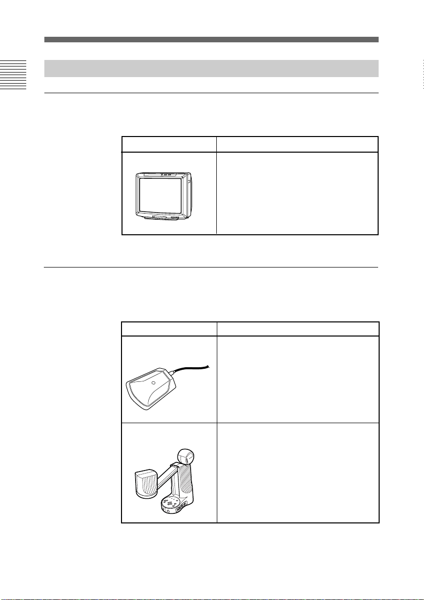
Unit Description
PCS-P150/P150P
Compact Processor
PCS-C150/C150P
Camera
Contains the video codec, audio codec,
echo canceler, network interfaces and
system controller.
This unit has an integral-type camera
and microphone.
Chapter 1
PCS-R150
Remote Commander
PCS-AC15
AC adaptor
Controls the Compact Processor.
This can also be used to operate a Sony
TV monitor.
Provides the power supply to the
Compact Processor.
Chapter 1 Preparation 13
System Configuration
Options
Chapter 1
TV monitor
Other options
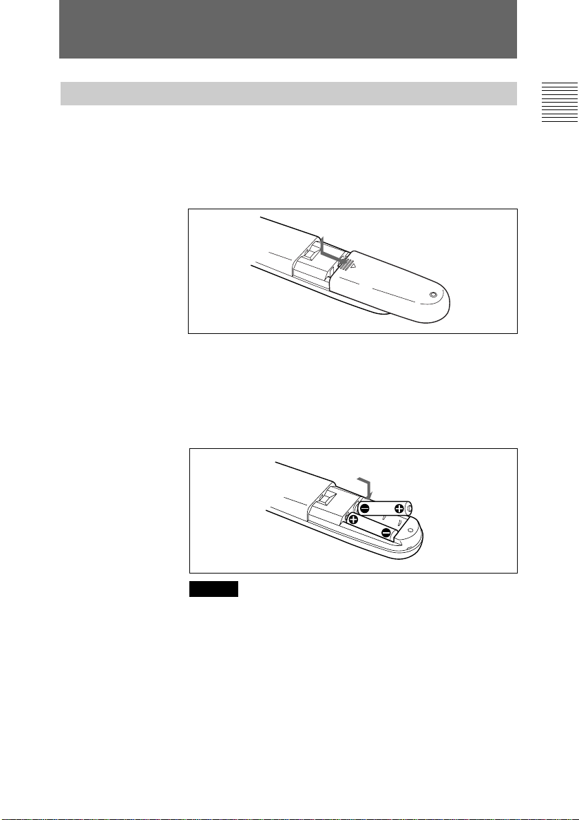
A TV monitor is required for your meetings.
Unit Description
TV monitor
A TV is used as a meeting monitor and
speaker. It displays the remote party,
graphics, and menus.
If you use a Sony TV, you can operate it
with the Remote Commander supplied with
the Compact Conference Package.
The following optional devices are also available to improve
your meetings.
Unit Description
PCS-A300
Microphone
PCS-DS150/DS150P
Document Stand
14 Chapter 1 Preparation
Allows you to accommodate extra two or
three participants.
You can connect two microphones.
However, you cannot use both the built-in
microphone and the external microphone at
the same time.
This document camera can transmit the
video signal to the Compact Processor
using infrared rays, without connecting a
cable to the Compact Processor.
You can easily transmit the RGB signal of a
PC to the Compact Processor.

Unit Description
PCS-I150
BRI Board
PCS-I151
V.35 Board
Provides two ISDN jacks. The connection
with 6B channels is available.
Provides the V.35 connector. The
connection via the V.35 interface is
available.
PCS-I152
LAN Board
PCS-K32
V.35 Conversion
Connector Cable
PCS-K60
S-video cord
Allows you to hold a meeting on the LAN
that corresponds to H.323.
Connects one end to the V.35 connector
(on the PCS-I151 V.35 Board) and the other
end to the terminal adapter. (1 m, 3.3 ft)
Connects one end to the S-video jack on
the video equipment and the other end to
the Compact Processor.
PCS-UC150
Upgrade Kit
Allows you to use this unit as the MCU
(Multipoint Control Unit).
Chapter 1
Chapter 1 Preparation 15

Chapter 1
Basic System Connection
Connect the TV monitor and the AC adaptor to the Compact
Processor, and connect to the ISDN line with the supplied
ISDN modular cable.
The following cables; the ISDN modular cable and the audio
cord, each cable is equipped with the color label. When
connecting these cables, match the label color with the color of
the connector name printed on the rear panel.
Notes
• Be sure to turn off all the equipment before making any
connections.
• If your TV has the 21-pin connector, use the supplied 21-pin
adaptor. (PCS-1500P only)
Compact Processor
Set the BACKUP
switch to ON.
MIC
(PLUG IN POWER)
POWER
to DC12V
DC12V T.120
1
2
to AUDIO
OUT
Audio cord
(1 m, 3.3 ft
(supplied))
16 Chapter 1 Preparation
AUDIO VIDEO
IN
IN
AUX
2
OUT
OUT
AUX
to audio input
AUX1
MONITOR
IR OUT
ISDN A
to VIDEO
OUT
MONITOR
S-video cord
(1.3 m, 4.3 ft
(supplied))
to S-video
input
21-pin adaptor (supplied
with PCS-1500P only)
PCS-AC15
AC adaptor
ISDN modular cable (5 m,
16.4 ft (supplied))
to ISDN A
TV monitor
Power cord
to ISDN
to a wall
outlet
to a wall
outlet
Preparing the System
Inserting Batteries into the Remote Commander
The supplied Remote Commander controls most of the
functions. This section describes how to insert batteries into the
Remote Commander.
1 Remove the battery compartment cover.
2 Insert two size AA (LR6) alkaline batteries (supplied) with
correct 3 and # polarity into the battery compartment.
When inserting the batteries, be sure to put the negative
end at first.
Chapter 1
Caution
Be sure to place the negative # end of the battery at first.
If you place the positive 3 end at first, there is a
possibility of damaging the insulated film covering the
battery and creating a short circuit.
3 Replace the cover.
Chapter 1 Preparation 17
Preparing the System
Chapter 1
Preparing the TV Monitor
Battery life
When the Remote Commander no longer functions properly,
replace both the batteries.
Notes on batteries
To avoid possible damage from battery leakage or corrosion,
observe the following:
• Be sure to insert the batteries in the correct direction.
• Do not mix old and new batteries, or different types of
batteries.
• Do not attempt to charge dry-cell batteries.
• If you do not intend to use the Remote Commander for a long
time, remove the batteries.
If battery leakage occurs, clean the battery compartment and
replace all the batteries.
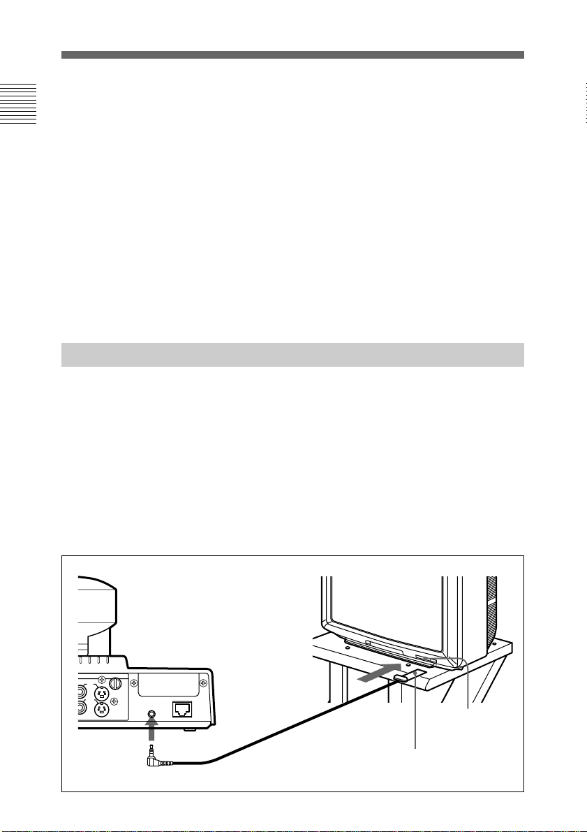
Insert the IR repeater below the remote sensor of the TV
monitor. Once you set the IR repeater, you can turn on the
Compact Processor and a Sony TV monitor together by
pressing the I/1 button on the Remote Commander.
If the IR repeater does not function properly, set MONITOR in
the Other Setup menu to MODE2 (PCS-1500); to MODE4
(PCS-1500P).
For details on the MONITOR setting, see “Other Setup menu”
on page 84.
VIDEO
IN
AUX
2
AUX1
OUT
AUX
MONITOR
to IR OUT
IR OUT
ISDN A
18 Chapter 1 Preparation
Remote sensor
IR repeater (supplied)
When using a Sony TV monitor
The TV monitor can be operated from the Remote
Commander.
For details on operating the Remote Commander, see “To
operate a Sony TV monitor” on page 120.
To adjust the TV monitor screen
Use the controls on the TV monitor to adjust the screen
(picture, hue, contrast, brightness, and sharpness).
For details on adjusting the screen, refer to the operating
instructions supplied with the TV monitor.
Note
Do not activate the surround function of the TV monitor. This
causes strange sounds since the echo canceler on the Compact
Processor will not function properly.
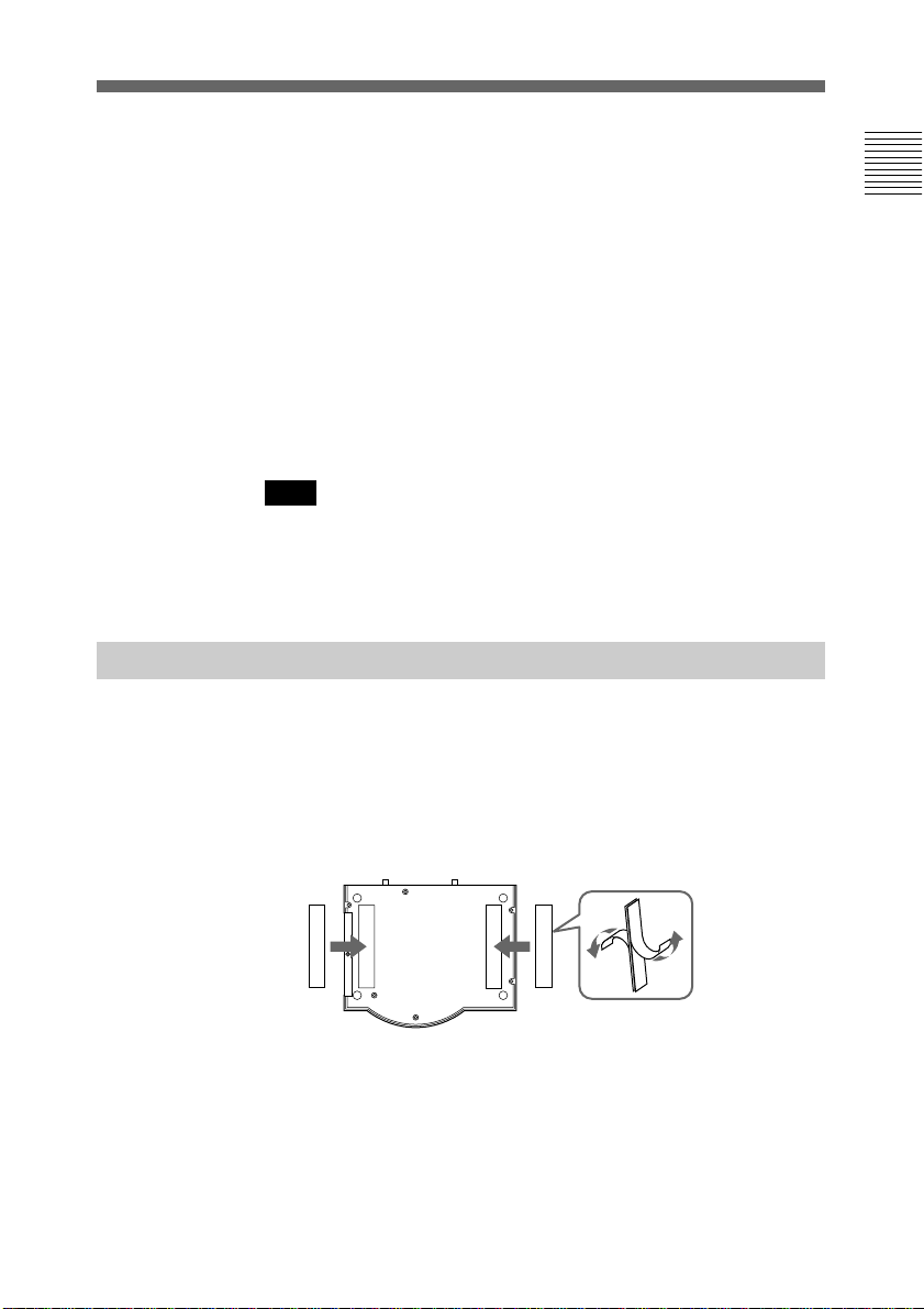
Installing the Compact Processor
When you install the Compact Processor, use the supplied
Velcro (long). This will prevent the Compact Processor from
falling down.
Chapter 1
1 Stick one side of the supplied Velcro (long) to the bottom
of the Compact Processor.
2 Stick the other side of the Velcro to the top of the TV
monitor.
3 Attach the Compact Processor and the TV monitor by
securing the Velcro.
Chapter 1 Preparation 19

Turning the System On/Off
This section describes how to turn on and off the Compact
Processor.
Chapter 1
Note
Set the CONF/DOC/TV selector on the Remote Commander to
“CONF” when operating the Compact Processor.
Turning On
The following describes how to turn on the Compact Processor.
1 Make sure the TV monitor is on standby.
For details on how to set the TV monitor into a standby
state, refer to the operating instructions supplied with the
TV monitor.
2 Turn on the power of any other equipment to be used
during the meeting.
3 Set the POWER switch on the rear of the Compact
Processor to on.
Soon, the Compact Processor and the TV monitor are
turned on.
The POWER lamps (green) on the camera and the
Compact Processor light up, and the self-diagnostic starts.
The picture shot by the local camera appears on the
monitor screen after the self-diagnostic is completed.
20 Chapter 1 Preparation
Rear
MIC
AUDIO VIDEO
IN
(PLUG IN POWER)
IN
AUX
1
2
DC12V T.120
POWER
AUX1
OUT
OUT
AUX
2
ISDN A
IR OUT
MONITOR
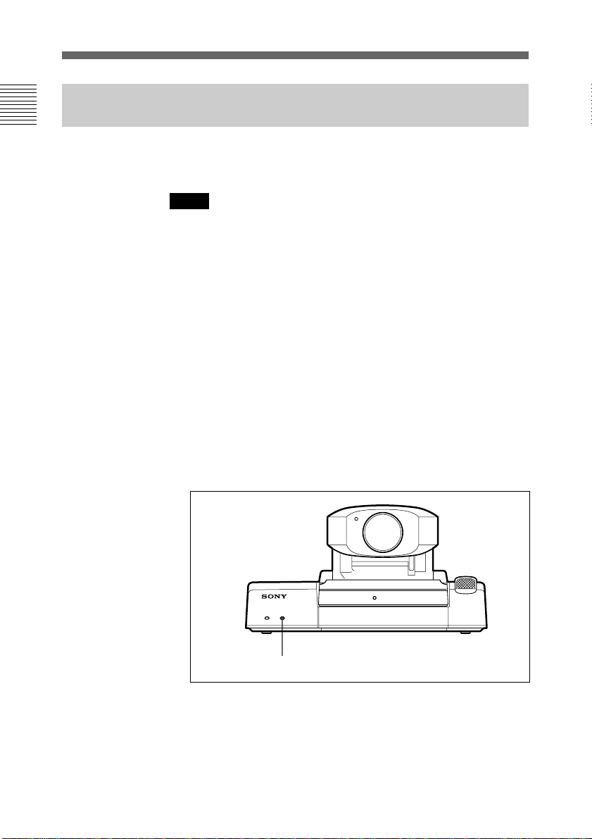
Front
POWER switch POWER lamps

When the Compact Processor is turned on for the first time
Sleep function
The ISDN Configuration (COUNTRY) menu appears on the
monitor screen after the self-diagnostic is completed.
Register your local system data on the ISDN Configuration
menus.
For details on the registration, see “Registering Local
Information” on page 60.
The Compact Processor is turned into sleep mode to save
power, if you do not operate the Compact Processor for about
10, 30, or 60 minutes.
The POWER lamp on the main unit flashes while in sleep
mode.
Once a call comes in, the sleep function is automatically
released.
To release the sleep function
Press any of the buttons on the Remote Commander.
To set the time that the unit turns into sleep mode
Set the time by setting SLEEP FUNCTION in the Other Setup
menu. If you do not want to use the sleep function, set SLEEP
FUNCTION to OFF.
Chapter 1
For details on the SLEEP FUNCTION setting, see “Other
Setup menu” on page 84.
Notes
• The POWER lamp on the camera does not flash even if the
system is in sleep mode.
• A Sony TV monitor is turned into standby mode.
Chapter 1 Preparation 21
Turning the System On/Off
Setting the System (Compact Conference Package) to be on Standby
Chapter 1
When the system is on standby, you can turn the system on
with the I/1 button on the Remote Commander.
Notes
• Do not turn off the POWER switch on the rear panel while
the menu is displayed on the monitor screen.
• When you have installed the optional PCS-I152 LAN Board,
and holding a meeting on a LAN, the Compact Processor on
standby cannot receive a call.
1 Press the I/1 button on the Remote Commander.
The indication “POWER OFF Are you sure?” appears on
the monitor screen.
2 Press the I/1 button on the Remote Commander.
Both the Compact Processor and the TV monitor are
turned into standby.
The STANDBY lamp (orange) lights up.
To cancel turning into standby
Press the CANCEL button on the Remote Commander in step
2.
22 Chapter 1 Preparation
STANDBY lamp

On the Guide Menu
When a menu is displayed, the guide menu appears on the
lower part of the monitor screen.
You can easily operate the Compact Processor under its
guidance. But, the guidance is in English only.
Menu
System Configuration
CONTROL
CAMERA
T. 120
STATUS
COMMUNICATION
MACHINE
SELECT:
SETUP
ISDN
ANSWER
AUDIO
OTHER
Guide menu
On the Version And Option Indications
You can check the Compact Processor version and the option
installed into the unit, with the Machine Information menu.
For details on the Machine Information menu, see “Machine
Information menu” on page 87.
Chapter 1
END: CANCEL
Machine Information
HOST VERSION:
BRI VERSION:
VCP VERSION:
DSP VERSION:
SOFTWARE OPTION:
OPTION BOARD:
HOST NAME:
IP ADDRESS:
Ver4.00
Ver3.28
Ver3.02 Ver1.00
Ver1.05 Ver1.00
None
LAN 08-00-46-XX-XX-XX
PCS-1500
1. 2. 3. 4
Machine Information menu
Exit: CANCEL
Chapter 1 Preparation 23

Turning the System On/Off
Turning Off
Chapter 1
The following describes how to turn off the Compact
Processor.
1 Set the POWER switch on the rear of the Compact
Processor to off.
2 Turn off the power of any other equipment to be used
during the meeting.
Notes
• If you are not going to use the system for an extended period,
set the POWER switch to off.
• You cannot receive any calls from remote parties if the
POWER switch is set to off.
24 Chapter 1 Preparation

Chapter 2
Basic Operation
During a Meeting
Calling a Remote Party
You can start a meeting with a remote party by dialing. Once
you have made a connection with the remote party, you can
begin talking just like normal phone call.
The following describes how to call a remote party.
You have to register your local system data and set up the
Compact Processor before starting a meeting.
For details on registration and setup, see Chapter 4
“Registration and Setup.”
Calling an Unregistered Remote Party
Chapter 2
The Manual Dial menu for connecting on a LAN is different
from the one for the ISDN line. When LINE I/F in the Dial
Setup menu is set to LAN, the Manual Dial LAN menu is
displayed.
When you access the Manual Dial menu again after you have
used the Manual Dial menu once, the last number dialed is
entered into the boxes. (Last-number redial function)
Chapter 2 Basic Operation During a Meeting 25
Calling a Remote Party
Notes
This function does not work in the following situations:
• Once you turned off the power or turned the Compact
Processor to standby/sleep.
• You have not dialed though you entered a number.
• When you display the Manual Dial menu using the one of the
number buttons on the Remote Commander.
Chapter 2
To connect via the ISDN lines
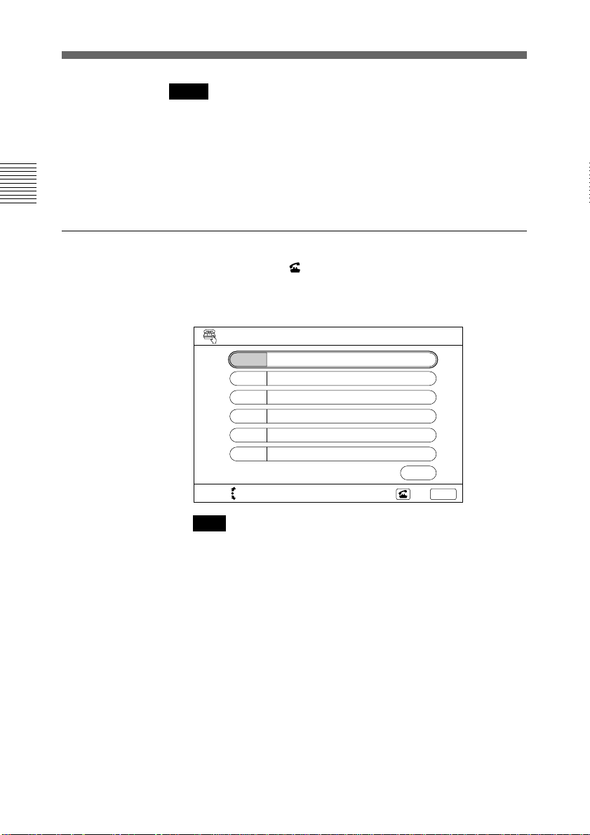
1 Press the DIAL ( ) button or one of the number buttons (0
– 9) on the Remote Commander.
The Manual Dial menu appears on the monitor screen.
SELECT: Dial? Yes:
Manual Dial
A1
A2
B1
B2
C1
C2
BRI
NUMBER OF LINES
6
No: CANCEL
Note
The B1 to C2 boxes are only displayed when you have
installed the optional PCS-I150 BRI Board.
2 Enter the telephone number of the remote party to have a
meeting with in the A1 and A2 boxes.
Move the joy stick up or down to select the box, then enter
the number with the number buttons on the Remote
Commander.
• To delete a telephone number, press the CLEAR button
on the Remote Commander. The number entered is
deleted.
• To copy a telephone number, press the LINE COPY
button or the joy stick on the Remote Commander. The
number entered are copied to the next box.
26 Chapter 2 Basic Operation During a Meeting
• To delete the last number, press the BACK SPACE
button on the Remote Commander, or move the joy stick
to the left. The last number is deleted.
Note
Do not enter your prefix number in these boxes.
3 Select the number of lines to be used.
Move the joy stick downward to select the NUMBER OF
LINES box, then move the joystick rightward or leftward
to set the number of lines.
If you want to check or change the settings of the Dial Setup
menu, follow step 4; dial the number, follow step 7. Since the
LINE I/F setting is displayed on the upper-right corner of the
Manual Dial menu, you can also check the setting in the
Manual Dial menu.
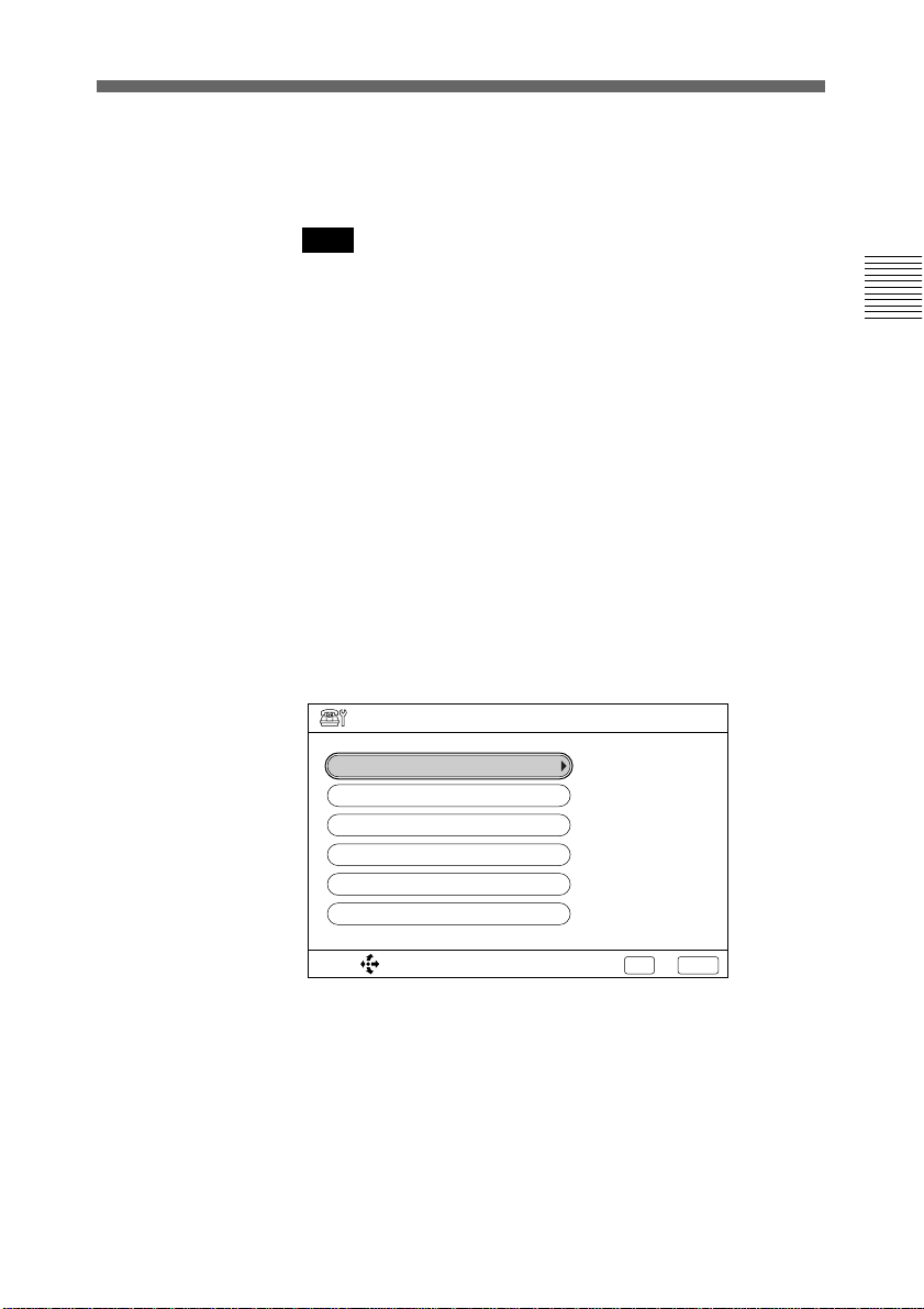
4 Press the EXEC button on the Remote Commander.
The Dial Setup menu appears on the monitor screen.
Dial Setup
LINE I/F
ISDN RATE
AUDIO MODE
VIDEO MODE
PREFIX
DATA
:ISDN BRI
:AUTO
:G. 728 & G. 722
:H. 261 CIF 15fps
:OFF
:OFF
Chapter 2
SELECT: Yes: EXEC
No: CANCEL
5 Set up or check the following items:
LINE I/F: Selects the line interface.
ISDN RATE: Selects the ISDN transfer rate.
AUDIO MODE: Selects the protocol for the audio
encoding.
VIDEO MODE: Selects the protocol for the video
encoding.
Chapter 2 Basic Operation During a Meeting 27
(Continued)

Calling a Remote Party
Chapter 2
6 Press the EXEC button on the Remote Commander.
PREFIX: Selects the prefix number setting.
DATA: Selects whether to have a T.120 data meeting.
For details on each setting of the items, see “On Items in
the Dial Setup Menu” on page 30.
• To select an item to be changed, select an item with the
joy stick on the Remote Commander, then press it.
• To set up an item, select a setting with the joy stick on the
Remote Commander, then press it.
• To cancel the setup, press the CANCEL button on the
Remote Commander.
Notes
• When using the Compact Precessor as the MCU, items
below cannot be set up:
ISDN RATE, AUDIO MODE, VIDEO MODE, DATA.
• When using a LAN, items below cannot be set up:
ISDN RATE, DATA.
The Manual Dial menu appears on the monitor screen
again.
7 Press the DIAL ( ) button on the Remote Commander.
The system dials the number that is input in step 2, and the
indication “Dialing” appears on the monitor screen.
When the connection is completed, the indication
“MEETING STARTS!” appears on the monitor screen.
To cancel dialing before the connection is completed
Press the CANCEL button on the Remote Commander.
To connect on a LAN
Notes
• Meetings on a LAN are only available when the optional
PCS-I152 LAN Board has been installed.
• The Manual Dial LAN menu is displayed only when LINE I/
F is set to LAN.
28 Chapter 2 Basic Operation During a Meeting

1 Press the DIAL ( ) button or one of the number buttons (0
– 9) on the Remote Commander.
The Manual Dial LAN menu appears on the monitor
screen.
Manual Dial
ADDRESS
LAN
Chapter 2
BANDWIDTH
SELECT: Dial? Yes:
768K
No: CANCEL
2 Enter the IP address (or the host name and domain name)
of the remote party to have a meeting with in the
ADDRESS box.
Enter the address (or the host name and domain name) with
the number buttons on the Remote Commander.
You can enter a dot by moving the joy stick on the Remote
Commander to the right.
3 Select the bandwidth.
Move the joy stick down to select the BANDWIDTH box,
then move the joy stick on the Remote Commander to the
right or left to set the bandwidth.
If you want to check or change the settings of the Dial Setup
menu, follow step 4 on page 27; dial the number, follow step 7
on page 28. Since the LINE I/F setting is displayed on the
upper-right corner of the Manual Dial LAN menu, you can also
check the setting in the Manual Dial LAN menu.
Chapter 2 Basic Operation During a Meeting 29
Calling a Remote Party
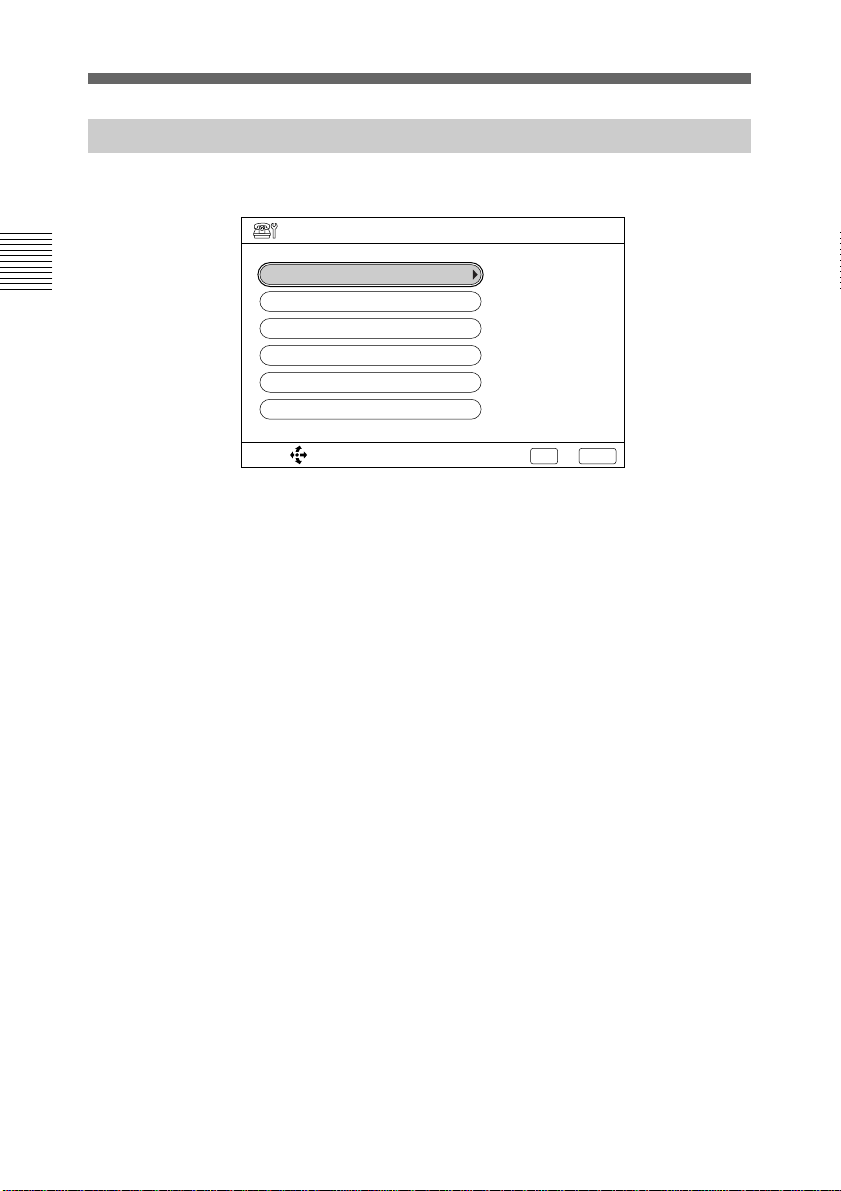
On Items in the Dial Setup Menu
The settings for the Dial Setup menu are as follows:
Dial Setup
Chapter 2
LINE I/F
ISDN RATE
AUDIO MODE
VIDEO MODE
PREFIX
DATA
SELECT: Yes: EXEC
:ISDN BRI
:AUTO
:G. 728 & G. 722
:H. 261 CIF 15fps
:OFF
:OFF
No: CANCEL
LINE I/F
ISDN BRI: Connects to a remote party via the normal ISDN
line.
ISDN BRI (Bonding): Connects to a remote party via the
Inverse Multiplexer interface.
“Bonding (Bandwidth on Demand Interoperability
Group)” is a trademark of THE BONDING
CONSORTIUM.
ISDN BRI (Speech): Connects to a normal phone to have a
voice meeting.
V.35 (with RS-366): Connects to a remote party via the V.35
interface by specifying the telephone number.
V.35 (without RS-366): Connects to a remote party via the
V.35 interface without specifying the telephone number.
LAN: Connects to a remote party using a LAN.
ISDN RATE
AUTO: Connects to a remote party with a normal ISDN line.
56K: Connects to a region or country with a 56 Kbps ISDN
transfer rate.
AUDIO MODE
G.722: The audio bandwidth is wider for better sound quality.
(7 kHz)
G.728 & G.722: The audio bandwidth is narrow but the
image quality is better. (G.728: 3.4 kHz)
30 Chapter 2 Basic Operation During a Meeting
 Loading...