

Page 1
3-836-774-12 (1)
Supplement for
Video
PCS-11/11P
Communication
System
操作ガイド
最初にお読みください!
Operation Guide
Please read it before proceeding!
Guide d’utilisation
Lisez-le avant de continuer!
Bedienanleitung
Lesen Sie sie bitte, bevor Sie fortfahren!
Guía de functionamiento
Léalo antes de continuar!
Guida per l’uso
Leggere attentamente prima di procedere!
JP
GB
FR
DE
ES
IT
CS
Guia de Operação
Leia antes de continuar!
PCS-11/11P
© 2004 Sony Corporation
PT
Page 2
ާпɁȲɔȾ
ʇʕ˂ᛏֿɂާпȾЭґᥓȪȹᜫȨɟȹȗɑ
ȬǿȪȞȪǾᛏֿɂǾɑȴȟȶȲΈȗȞȲɥȬ
ɞȻǾཌདɗȽȼȾɛɝඳɗ۾ȤȟȽȼᡵ
ȾȷȽȟɞȦȻȟȕɝǾԲ᪙ȺȬǿ
ɥ᩻ȣȲɔȾඒɁȦȻɥȭȝަɝȢȳȨȗǿ
ឬ֖᚜ᇉɁ֞
ᝢంȝɛɆᛏֿ
ȺɂǾඒɁɛșȽ᚜ᇉ
ɥȪȹȗɑȬǿ᚜ᇉɁ
ю߁ɥɛȢျᜓȪȹȞ
ɜట୫ɥȝᝣɒȢȳȨ
ȗǿ
ާпɁȲɔɁาᬱɥަɞ
¶ᵻ ¹ ʤ˂ʂɁาᬱɥɛȢȝᝣɒȢȳȨȗǿ
ްఙཟ೫ɥȬɞ
ᩋఙᩖǾާпȾȝΈȗȗȲȳȢȲɔȾǾްఙཟ೫ɥ
ȬɞȦȻɥȝȬȬɔȪɑȬǿ
ཟ೫Ɂю߁ɗ៵ႊȾȷȗȹɂǾȝ៳ȗ˨ȥࣆɑȲɂ
ʇʕ˂Ɂɿ˂ʝʃሻՠȾȧᄾᝬȢȳȨȗǿ
᪩ȪȲɜΈɢȽȗ
ȬȣȾǾȝ៳ȗ˨ȥࣆɑȲɂʇʕ˂Ɂɿ˂ʝʃሻՠ
ȾȧᣵፅȢȳȨȗǿ
˥ˢǾႱࢠȟᠭȠȲɜ
e ཽȟҋȲɜ
e ႱࢠȽᬩǾȾȝȗȟȪȲɜ
e юȾ෩ǾႱ࿎ȟоȶȲɜ
e ᛏֿɥᕶȻȪȲɝɷʭʝʗʍʒɥᆍૺȪȲȻȠɂ
m
1 ໃɥҒɞǿ
2 ໃɽ˂ʓɗፖɽ˂ʓɥȢǿ
3 ȝ៳ȗ˨ȥࣆɑȲɂʇʕ˂Ɂɿ˂ʝʃሻՠȾᣵፅ
Ȭɞǿ
ȦɁ᚜ᇉɁาᬱɥ
ަɜȽȗȻǾཌདɗ
ȽȼȾɛɝඳɗ۾
ȤȟȽȼᡵȾȷ
ȽȟɞȦȻȟȕɝɑ
Ȭǿ
ȦɁ᚜ᇉɁาᬱɥ
ަɜȽȗȻǾɗȰ
ɁɁȾɛɝȤȟ
ɥȪȲɝ֚ᣃɁ࿎ֿȾ
ૺɥ˫țȲɝȬɞȦ
ȻȟȕɝɑȬǿ
าɥȬᜤհ
ᚐའɥᇣඨȬɞᜤհ
ᚐའɥᇉȬɞᜤհ
JP
2
ާпɁȲɔȾ
Page 3

ɂȫɔȹȝΈȗȾȽ
ɞȻȠȾ
ȦɁͽʨʕʯɬʵɂǾ² ٥ཟᩖɁʐ
ʶʝឰȺǾஓࢠɁឰɥܿɔɞȻȦ
ɠȞɜጶȬɞɑȺɁͽɥዊԨȾᝢ
ȪȹȗɑȬǿɛɝᝊȪȗͽศɗ
ឰȾᛵȽȨɑȩɑȽᜫްȾȷȗȹ
ɂǾࠖɁ ÃÄÒÏÍ Ɂᝢంɥ
ȧᜄȢȳȨȗǿ
ᝢంȾȷȗȹ
టൡɁᝢంɂࠖɁ CD-ROM
Ⱦ PDF ࣻȺоȶȹȗɑȬǿᝢ
ంɥȝᝣɒȾȽɞȾɂǾБдпве
Бгтпвбф
ʛʇɽʽȾ БдпвеБгтпвбфТебдет
ȟɮʽʃʒ˂ʵȨɟȹȗȽȗکնɂǾ
´ ʤ˂ʂȾᇉȪȲʥ˂ʪʤ˂ʂȞɜʊ
ɰʽʷ˂ʓȪȹȢȳȨȗǿ
®ª
Тебдет ȟᛵȺȬǿ
ᝢంɁȞȲ
®
2 b КбрбоеуеȉȻȗșʟɫɮʵջ
Ɂ ÐÄÆ ɥʊʠʵɹʴʍɹȬɞǿ
БдпвеБгтпвбфТебдет ȟᠭӦ
ȪǾటൡɁᝢంɁ᚜ጤȟ႕ᬂ
Ⱦ᚜ᇉȨɟɑȬǿ
bᄻඒȉɁյᬱᄻɥɹʴʍɹȬɞȻǾȰ
ɁҋȪɁʤ˂ʂȟ᚜ᇉȨɟɑȬǿ
БдпвеБгтпвбфТебдетµ®°К Ɂ
ɮʽʃʒ˂ʵ
БдпвеБгтпвбфТебдетµ®°К ɥɮʽ
ʃʒ˂ʵȬɞȲɔȾᛵȽʙ˂ʓɰɱ
ɬǾʇʟʒɰɱɬɂ˩ɁȻȝɝȺ
Ȭǿ
®
e Йофем
e Нйгтпупжф
e ¶´ÍÂ ˨Ɂ ÒÁÍ
e ·°ÍÂ ˨Ɂʙ˂ʓʑɭʃɹɁሳȠ
Реофйхн®ɑȲɂ 100 ʛ˂ʅ
ʽʒ૰ɁʡʷʅʍɿɥଃᢐȪȲʛ
ʇɽʽ
ЧйодпчуНйммеоойхнǾЧйодпчу
ОФ
Чйодпчу²°°° ᪃
߁ᦀ
®
Чйодпчу
®ªª
´®°УетцйгеРбглµ ɑȲɂ
®ªª
98 SEǾ
1 ÃÄÒÏÍ ʓʳɮʠȾࠖɁ ÃÄ
ТПНȈНбохбмужптЦйдеп
ГпннхойгбфйпоУщуфенȉɥ
ષоȬɞǿ
ȪɃɜȢȬɞȻǾ႕ᬂȾ CD-ROM
Ɂю߁ȟ᚜ᇉȨɟɑȬǿ
. . . . . . . . . . . . . . . . . . . . . . . . . . . . . . . . . . . . . . . . . . . . . . . . . . . . . . . . . . . . . . . . . . . . . . .
* БдпвеǾБгтпвбф ɂ БдпвеУщуфенуЙогптрптбфедᴥɬʓʝʁʃʐʪʄᇋᴦɁףൈ
ȺȬǿ
** ЧйодпчуǾЧйодпчуОФɂǾዢّНйгтпупжфГптрптбфйпоɁዢّȝɛɆɁّȾȝ
Ȥɞᄊ᧸ףൈȺȬǿ
БдпвеБгтпвбфТебдет ɂ˩ᜤɁʥ˂
ʪʤ˂ʂȞɜఊ࿂ȟི୳ȺоȺȠ
ɑȬǿ
ɂȫɔȹȝΈȗȾȽɞȻȠȾ
3
JP
Page 4

ஓటտȤǽèôô𺯯
ччч®бдпве®гп®кр¯ртпдхгфу¯
бгтпвбф¯тебдуфер®ифнм
ԈዢտȤǽèôô𺯯
ччч®бдпве®гпн¯ртпдхгфу¯
бгтпвбф¯тебдуфер®ифнм
ඔࡻտȤǽèôô𺯯
ччч®бдпве®гпᵪ¯ртпдхгфу¯
бгтпвбф¯бгттгеофехтп®ифнм
JP
4
ɂȫɔȹȝΈȗȾȽɞȻȠȾ
Page 5
ᄻඒ
ឬ֖®®®®®®®®®®®®®®®®®®®®®®®®®®®®®®®®®®®®®®®®®®®
า®®®®®®®®®®®®®®®®®®®®®®®®®®®®®®®®®®®®®®®®®®®·
ȾȷȗȹɁާп˨Ɂȧา ®®®®®¹
ໃɥоɟɞ ®®®®®®®®®®®®®®®®®®®®®®®®®®®®®® ±°
ᄾɥ֣ɆҋȬ ®®®®®®®®®®®®®®®®®®®®®®®®®®® ±±
ЅɗᬩۦɥᝩኮȬɞ ®®®®®®®®®®®®®®®® ±´
ɵʫʳɬʽɺʵȻʄ˂ʪɥᝩኮȬ
ɞ ®®®®®®®®®®®®®®®®®®®®®®®®®®®®®®®®®®®®® ±´
ᬩᦀɥᝩኮȬɞ®®®®®®®®®®®®®®®®®®®®®® ±µ
ឰɥጶȬɞ ®®®®®®®®®®®®®®®®®®®®®®®®®®® ±
و፷ɥҒɞ®®®®®®®®®®®®®®®®®®®®®®®®®®®®® ±
ʁʃʐʪɥʃʉʽʚɮৰȾ
Ȭɞ ®®®®®®®®®®®®®®®®®®®®®®®®®®®®®®®®®® ±
ʢʵʡɥ᚜ᇉȬɞ ®®®®®®®®®®®®®®®®®®®®®®® ±¸
ʁʃʐʪɁፖ ®®®®®®®®®®®®®®®®®®®®®®®®®®® ±¹
ፖᴥÌÁÎ ፖᴦ®®®®®®®®®®®®®®® ±¹
ፖᴥÉÓÄÎ ፖᴦ ®®®®®®®®®®®®® ²°
റ ®®®®®®®®®®®®®®®®®®®®®®®®®®®®®®®®®®®®®®®®®® ²±
JP
ࠖɁ CD-ROM ȾɂǾటൡɁɛɝᝊȪ
ȗষڨɥᜤᢐȪȲᝢంȟՖ᧸Ȩɟ
ȹȗɑȬǿͽɶɮʓȻ΄ȮȹȝᝣɒȢ
ȳȨȗǿ
ᄻඒ
JP
5
Page 6

˩ᜤɁาɥަɜȽȗȻǾ ཌདɗȾɛɝ
ඳɗ۾ȤȟȾȷȽȟɞȦȻȟȕɝɑȬǿ
ÁÃ ໃɽ˂ʓɗ ÄÃ ໃፖɽ˂
ʓɥϾȷȤȽȗ
ÁÃ ໃɽ˂ʓɗ ÄÃ ໃ
ፖɽ˂ʓɥϾȷȤɞȻǾཌ
དɗɁՁىȻȽɞȦȻ
ȟȕɝɑȬǿ
e ɽ˂ʓɥӏࡾȪȲɝǾϾ
ȷȤȲɝȪȽȗǿ
e ȗɕɁɥɁȮȲɝǾ
ȶȶȲɝȪȽȗǿ
e ྒبщȾᣋȸȤȲɝǾӏ
ྒȪȲɝȪȽȗǿ
e ɽ˂ʓɥȢȻȠɂǾ
ȭʡʳɺɥધȶȹȢǿ
˥ˢǾɽ˂ʓȟϾɦȳɜǾʇ
ʕ˂Ɂɿ˂ʝʃሻՠȾ૰
ɥȧΗᭅȢȳȨȗǿ
ɁȕȲɞکɗǾบཽǾ຺ǾɎ
ȦɝɁ۹ȗکȾɂᏚȞȽȗ
ཌདɗɁՁىȻȽɞȦ
ȻȟȕɝɑȬǿ
JP
6
ឬ֖
Page 7
˩ᜤɁาɥަɜȽȗȻǾ ȤȟɥȪȲɝ֚ᣃɁ࿎ֿȾ
ૺɥ˫țɞȦȻȟȕɝɑȬ
˪ާްȽکȾᜫᏚȪȽȗ
ȣɜȷȗȲիɁ˨ɗϿȗȲ
ȻȦɠȾᜫᏚȬɞȻǾυɟȲ
ɝᕶȴȲɝȪȹȤȟɁՁى
ȻȽɞȦȻȟȕɝɑȬǿɑ
ȲǾᜫᏚˁɝȤکɁ
࣊ɥЭґȾȝᆬȞɔȢȳȨ
ȗǿ
ᣮތɥɈȨȟȽȗ
ᣮތɥɈȨȣȻǾటൡю
ȾྒȟȦɕɝǾᄉཽǾᄉཌȽ
ȼȟᠭȦɝǾɗȤȼɁՁىȾ
ȽɞȦȻȟȕɝɑȬǿ
ፖɁ᪨ɂໃɥҒɞ
ໃɥоɟȲɑɑȺໃ
ɽ˂ʓɗፖɻ˂ʠʵɥ
ፖȬɞȻǾɗ᪩ɁՁى
ȾȽɞȦȻȟȕɝɑȬǿ
ࠖɁ ÁÃ ɬʊʡʉ˂ɗǾໃɽ˂
ʓǾፖɽ˂ʓɥΈș
ࠖɁ ÁÃ ɬʊʡʉ˂ɗ
ໃɽ˂ʓǾፖɽ˂ʓɥΈɢ
ȽȗȻǾɗ᪩ɁՁىȾ
ȽɞȦȻȟȕɝɑȬǿ
ȿɟȲȺໃʡʳɺȾȨɢɜȽȗ
ȿɟȲȺໃʡʳɺɁ
ȠࢃȪɥȬɞȻǾɁՁى
ȻȽɞȦȻȟȕɝɑȬǿ
ȿɟȲȺ ÁÃ ɬʊʡʉ˂ȾȨɢɜ
Ƚȗ
ɁՁىȻȽɞȦȻȟȕ
ɝɑȬǿ
ґᜓɗᣲɥȪȽȗ
ཌདɗǾȤȟɁՁىȻȽ
ɞȦȻȟȕɝɑȬǿюɁཟ
೫ɗεျɂȝ៳ȗ˨ȥࣆɑ
Ȳɂʇʕ˂Ɂɿ˂ʝʃሻՠ
ȾȧΗᭅȢȳȨȗǿ
ȝоɟɁ᪨ɂǾໃɥҒȶȹໃ
ʡʳɺɥȢ
ໃɥፖȪȲɑɑȝ
оɟɥȬɞȻǾɁՁى
ȻȽɞȦȻȟȕɝɑȬǿ
ࠖɁ ÁÃ ɬʊʡʉ˂ɂްȨɟȲ
ᛏֿ۶ȾɂΈႊȪȽȗ
ްȨɟȲᛏֿ۶ȾΈႊ
ȬɞȻǾ᪩ɁՁىȾȽɞȦ
ȻȟȕɝɑȬǿ
ሉӦȨȮɞȻȠɂໃɽ˂ʓǾፖ
ɽ˂ʓɥȢ
ፖȪȲɑɑሉӦȨȮɞȻǾ
ɽ˂ʓȟϾȷȠǾཌདɗ
ɁՁىȻȽɞȦȻȟȕɝɑ
Ȭǿ
7
า
JP
Page 8

˩ᜤɁาɥަɜȽȗȻǾ ȤȟɥȪȲɝ֚ᣃɁ࿎ֿȾ
ૺɥ˫țɞȦȻȟȕɝɑȬ
ᄽߪஓбȾȲɞکǾྒبщɁᣋ
ȢȾɂᏚȞȽȗ
۰ȪȲɝǾ᪩ȪȲɝȬɞ
ȳȤȺȽȢǾʶʽʄɁ࿑Ⱦ
ɛɝཌདɁՁىȻȽɝɑȬǿ
࿑Ⱦሻ᪨ȾᏚȢȻȠȽȼɂ
ȧาȢȳȨȗǿ
юȾ෩ɗႱ࿎ɥоɟȽȗ
෩ɗႱ࿎ȟоɞȻཌདɗ
ɁՁىȻȽɞȦȻȟȕɝ
ɑȬǿ
˥ˢǾ෩ɗႱ࿎ȟоȶȲȻȠ
ɂǾȬȣȾໃɥҒɝǾໃ
ɽ˂ʓɗፖɽ˂ʓɥȗ
ȹǾȝ៳ȗ˨ȥࣆɑȲɂʇ
ʕ˂Ɂɿ˂ʝʃሻՠȾȧᄾ
ᝬȢȳȨȗ
JP
8
า
Page 9
ȾȷȗȹɁާп
˨Ɂȧา
ǾᄉྒǾᄉཌǾᆍᚺȽȼɥᤧȤɞȲ
ɔǾ˩ᜤɁาᬱɥȭȝަɝȢȳȨ
ȗǿ
e ཌɁ˹ȾоɟȽȗǿʁʱ˂ʒȨȮȲ
ɝǾґᜓǾӏྒȪȽȗǿ
e ЭȪȽȗǿ
e ްȨɟȲሗ᭒ɁɥΈႊȬɞǿ
e ᴨȻᴪɁտȠɥඩȪȢоɟɞǿ
e ɥΈȗҒȶȲȻȠǾᩋᩖΈႊȪ
ȽȗȻȠɂǾɝҋȪȹȝȢǿ
e ȪȗȻΈႊȪȲǾሗ᭒Ɂᤏ
șɥຉȯȹΈɢȽȗǿ
ɕȪɁȟɟȲȻȠɂǾо
ɟɁɥɛȢɈȠȻȶȹȞɜǾȪȗ
ɥоɟȹȢȳȨȗǿ˥ˢǾȟᡵ
ͶȾȷȗȲȻȠɂǾ෩ȺɛȢȗํȪ
ȹȢȳȨȗǿ
టൡɥࣔȬɞکնɂǾюᖽɁ
ɥߴټԇޙࣔ࿎ȻȪȹѿျȬɞ
ᛵȟȕɝɑȬɁȺǾʇʕ˂Ɂɿ˂ʝ
ʃሻՠȾȧᄾᝬȢȳȨȗǿ
ȾȷȗȹɁާп˨Ɂȧา
JP
9
Page 10
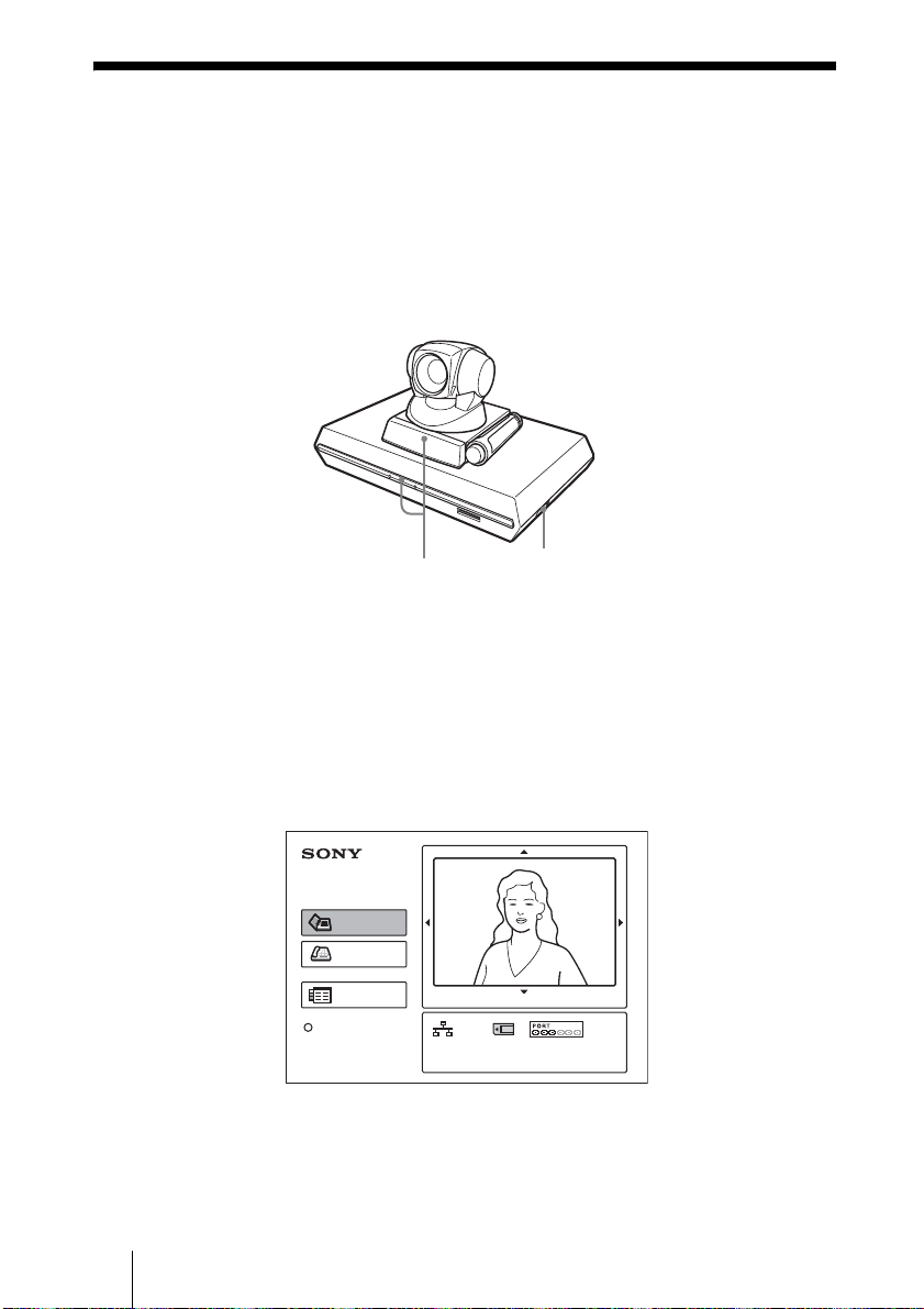
ໃɥоɟɞ
1 ʬʕʉ˂ႊʐʶʝɁໃɥоɟɞǿ
2 ឰȺΈႊȬɞȰɁɁൡبɁໃɥоɟɞǿ
3 ɽʩʯʕɻ˂ʁʱʽʉ˂ʩʔʵծϫᬂɁໃʃɮʍʋɥɴʽᴥ"
ϫᴦȾȬɞǿ
ɵʫʳ
ɽʩʯʕɻ˂ʁʱʽ
ʉ˂ʩʔʵ
РПЧЕТ ʳʽʡ
ໃʃɮʍʋ
ȪɃɜȢȬɞȻǾɽʩʯʕɻ˂ʁʱʽʉ˂ʩʔʵɁໃȟоɝɑȬǿ
ɽʩʯʕɻ˂ʁʱʽʉ˂ʩʔʵҰᬂɁ ³ ȷɁʳʽʡȻɵʫʳɁ
РПЧЕТ ʳʽʡȟȗȶȲɦȬɌȹཟཌྷȪǾȰɁǾРПЧЕТ ʳʽʡ
ȳȤȟ፲ᓨȾཟཌྷȪɑȬǿ
ʬʕʉ˂ႊʐʶʝȾɂʳʽʋʭ˂ʫʕʯ˂ȟ᚜ᇉȨɟǾᒲґϫɁɵʫ
ʳȟќȪȹȗɞЅɕ᚜ᇉȨɟɑȬǿ
ፖ
ɬʓʶʃ࢝
ʊɮʮʵ
ʫʕʯ˂
ʢʵʡ᚜ᇉ
ª
ȦɁͽɶɮʓȾᜤᢐɁʳʽʋʭ˂ʫʕʯ˂Ɂɮʳʃʒɂ ÉÓÄÎ ʰʕʍʒ
ЙРº°®°®°®°
ЦйдепºНбйо
ÐÃÓ·¶¸ ΈႊɁȺȬǿÉÓÄÎ ʰʕʍʒ ÐÃÓ³¸´ ΈႊɂǾÉÓÄÎ
ʧ˂ʒɮʽʂɻ˂ʉ˂Ɂ᚜ᇉȟႱȽɝɑȬǿ
႕ᜏᝩ
ª
ЙУДОº°±²³´µ¶·¸¹±²
БхдйпºНЙГ¨ЙОФ©«БХШ
JP
10
ໃɥоɟɞ
Page 11
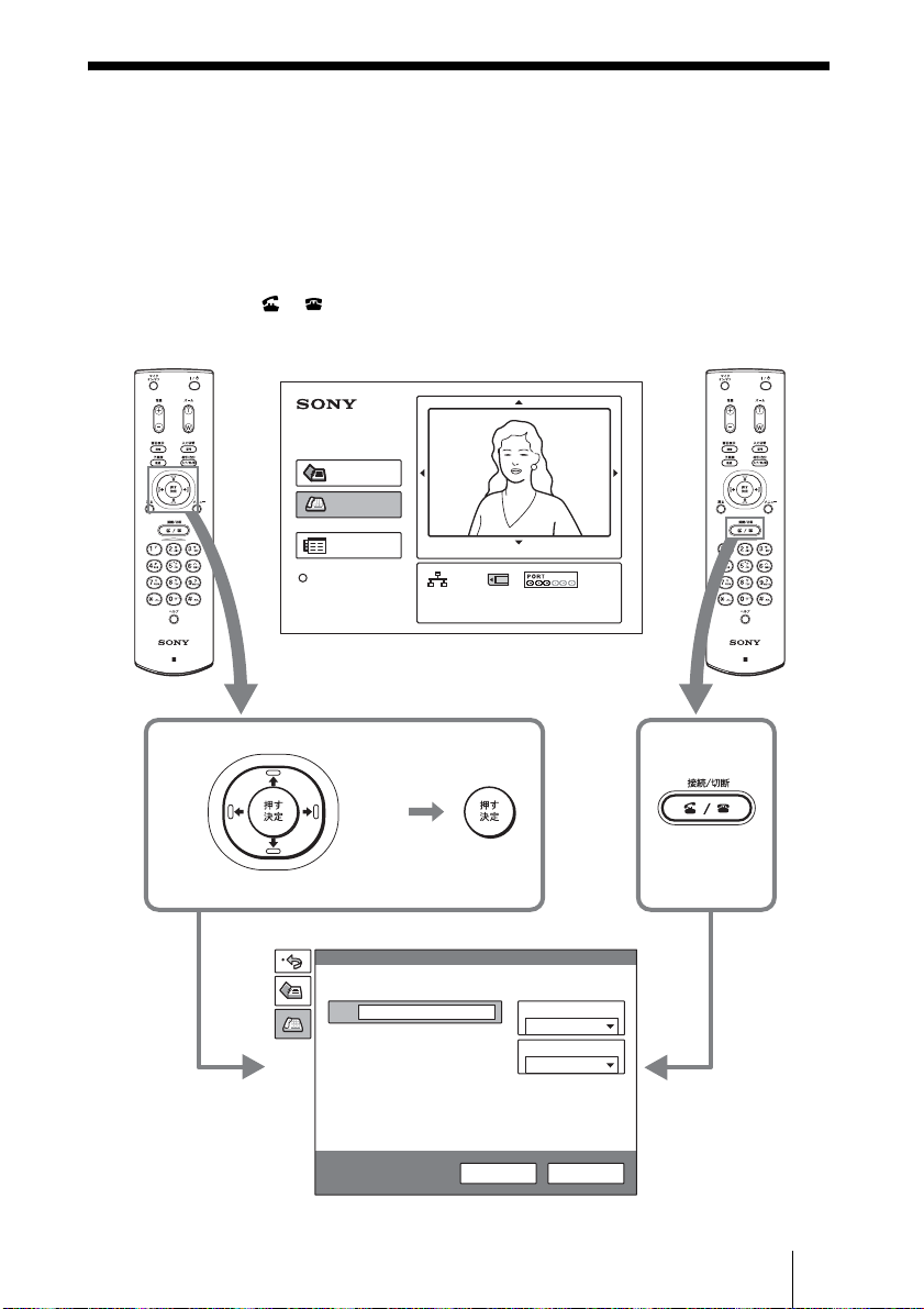
ᄾɥ֣ɆҋȬ
ȦȦȺɂǾɬʓʶʃ࢝Ⱦᄊ᧸ȨɟȹȗȽȗᄾɥ֣ɆҋȬศɥᝢ
ȪɑȬǿ
1 ʴʬɽʽɁ V¯v¯B¯b ʦʉʽɥઃȪȹʳʽʋʭ˂ʫʕʯ˂ɁȈʊɮ
ʮʵȉɥᤣɆǾขްʦʉʽɥઃȬǿɑȲɂǾʴʬɽʽɁፖᴬҒ
ᴥ ¯ ᴦʦʉʽɥઃȬǿ
ʊɮʮʵʫʕʯ˂ȟ᚜ᇉȨɟɑȬǿ
ፖ
ɬʓʶʃ࢝
ʊɮʮʵ
ʫʕʯ˂
ʢʵʡ᚜ᇉ
PCS-R1 PCS-R1
ʳʽʋʭ˂ʫʕʯ˂
ЙРº°®°®°®°
ЦйдепºНбйо
႕ᜏᝩ
ЙУДОº°±²³´µ¶·¸¹±²
БхдйпºНЙГ¨ЙОФ©«БХШ
˨ȾሉӦ
ࡿȾ
ሉӦ
ծȾ
ሉӦ
ɑȲɂ
˩ȾሉӦ
ʊɮʮʵ
ÉÐ
ᝊጯᜫް
و፷ሗҝ
ÌÁÎ
ÌÁÎΈႊ࢛ڒ
±°²´Ëâðó
ʊɮʮʵ ίސ
ʊɮʮʵʫʕʯ˂
ᄾɥ֣ɆҋȬ
11
JP
Page 12
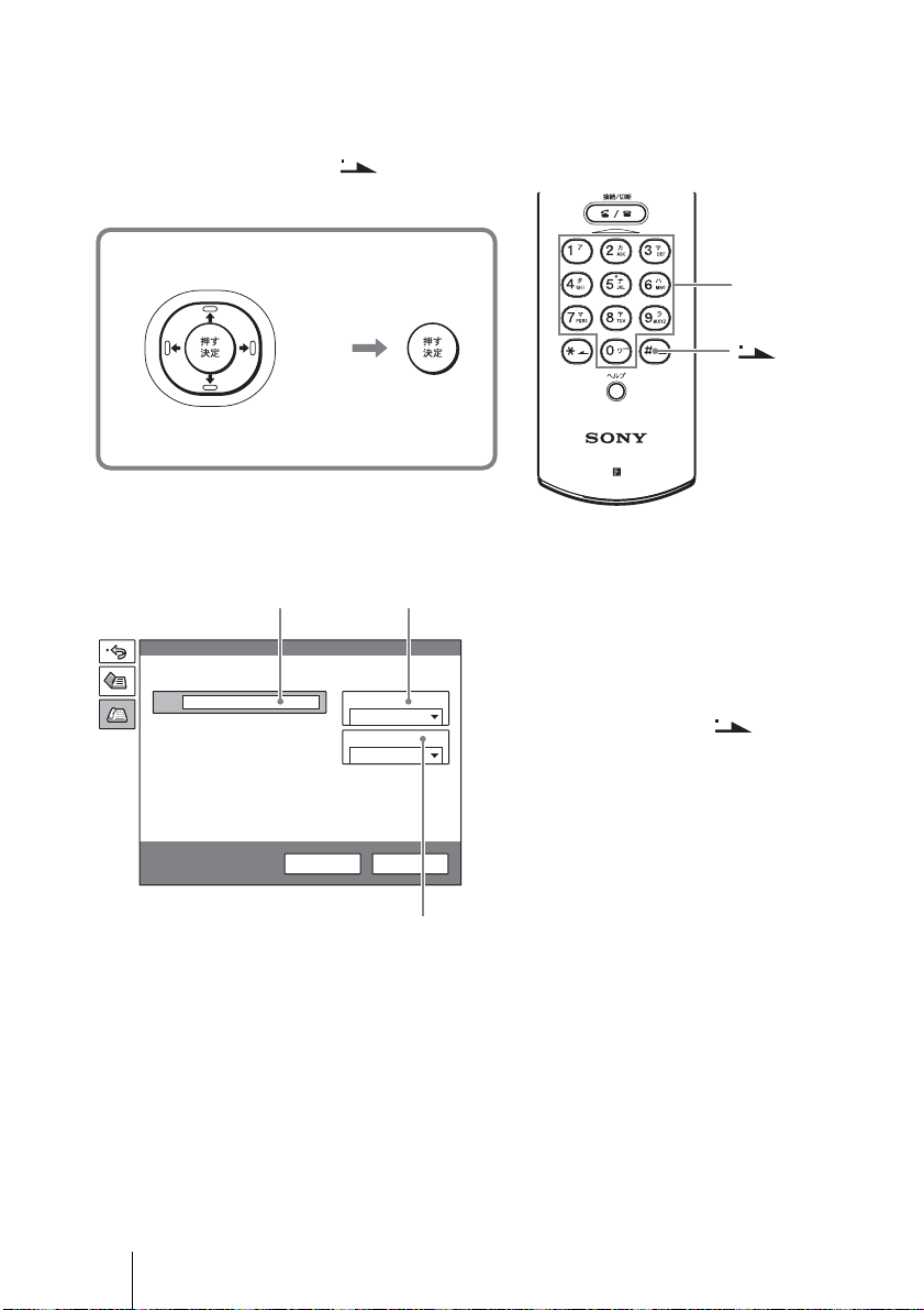
2 ʊɮʮʵʫʕʯ˂ɥᜫްȬɞǿ
ʴʬɽʽɁ V¯v¯B¯b ʦʉʽɥઃȪȹᬱᄻɥᤣɆǾขްʦʉʽɥઃȪ
ȹขްȪɑȬǿ
ୣޏʦʉʽȻ ʦʉʽȺୣϏɥоӌȪɑȬǿ
˨ȾሉӦ
ࡿȾ
ሉӦ
˩ȾሉӦ
ÌÁÎ ɥΈႊȬɞکն
2
ʊɮʮʵ
ÉÐ
ᝊጯᜫް
ծȾ
ሉӦ
و፷ሗҝ
ÌÁÎ
ÌÁÎΈႊ࢛ڒ
±°²´Ëâðó
ʊɮʮʵ ίސ
1
ୣޏʦʉʽ
ʦʉʽ
PCS-R1
1Ȉو፷ሗҝȉɥᤣɆǾ᚜ᇉȨɟ
ɞᬱᄻȞɜ ÌÁÎ ɥᤣɉǿ
2 ÉÐ ɬʓʶʃоӌඊɥᤣɆǾʴʬ
ɽʽɁୣޏʦʉʽȻ ʦʉʽ
¨ ʞʴɴʓᴦȺᄾɁ ÉÐ ɬʓʶ
ʃɥоӌȬɞǿ
3 b ÌÁÎ Έႊ࢛ڒȉɥᤣɆǾΈႊ
Ȭɞ࢛ڒࢥɥᤣɉǿ
JP
12
ᄾɥ֣ɆҋȬ
3
Page 13
ÉÓÄÎ و፷ɥΈႊȬɞکն
و፷ሗҝ
ÉÓÄÎ
Έႊو፷ୣ
¶ᴿ
1
1 bو፷ሗҝȉɥᤣɆǾ᚜ᇉȨɟɞ
ᬱᄻȞɜ ÉÓÄÎ ɥᤣɉǿ
2 ᝈႭհоӌඊɥᤣɆǾʴʬɽ
ʽɁୣޏʦʉʽȺᄾɁو፷Ⴍ
հɥоӌȬɞǿ
2
ʊɮʮʵ
Á
3 bΈႊو፷ୣȉɥᤣɆǾΈႊȬɞ
ÉÓÄÎ و፷Ɂʋʭʽʗʵୣɥᤣ
ʊɮʮʵ ίސ
ɉǿ
3
3 ʴʬɽʽɁ V¯v¯B¯b ʦʉʽɥઃȪȹʊɮʮʵʫʕʯ˂ɁȈʊɮʮ
ʵȉɥᤣɆǾขްʦʉʽɥઃȬǿɑȲɂǾʴʬɽʽɁፖᴬҒ
ᴥ ¯ ᴦʦʉʽɥઃȬǿ
ᄾϫȻȷȽȟɞȻȈʩ˂ʐɭʽɺɥܿɔɑȬǿȉȻ᚜ᇉȨɟǾ˩Ɂɛ
șȽ႕ᬂȾȽɝɑȬǿ
ᒲґϫɁЅ
ᄾϫɁЅ
ᄾɥ֣ɆҋȬ
13
JP
Page 14
ЅɗᬩۦɥᝩኮȬɞ
ɵʫʳɬʽɺʵȻʄ˂ʪɥᝩኮȬɞ
ᣮαȪȹȗȽȗȻȠ
ʴʬɽʽɁ V¯v¯B¯b ʦʉʽɥઃȪȹʳʽʋʭ˂ʫʕʯ˂ɁЅɥᤣ
ɆǾขްʦʉʽɥઃȪɑȬǿȰɁǾV¯v¯B¯b ʦʉʽɥઃȪȹɵʫ
ʳɬʽɺʵɥᝩኮȪǾʄ˂ʪʦʉʽɥઃȪȹʄ˂ʪɥᝩኮȪɑȬǿᝩ
ኮȪጶȶȲɜขްʦʉʽɥઃȪɑȬǿ
ɬʽɺʵɁᝩኮ
˨ȾሉӦ
ࡿȾ
ሉӦ
ծȾ
ሉӦ
˩ȾሉӦ
PCS-R1
ʄ˂ʪɁᝩ
Ѕȟ۾ȠȢȽɞ
ЅȟߴȨȢȽɞ
ᣮαȪȹȗȽȗȻȠɂƂ ᣮα˹ɂƂ
ፖ
ɬʓʶʃ࢝
ʊɮʮʵ
ʫʕʯ˂
ʢʵʡ᚜ᇉ
Éк°®°®°®°
ЦйдепºНбйо
႕ᜏᝩ
ÉÓÄκ°±²³´µ¶·¸¹±²
БхдйпºНЙГ¨ЙОФ©«БХШ
JP
14
ЅɗᬩۦɥᝩኮȬɞ
ᒲґϫɁЅ
ᄾϫɁЅ
Page 15
ᣮαȪȹȗɞȻȠ
ʴʬɽʽɁ V¯v¯B¯b ʦʉʽȻʄ˂ʪʦʉʽȺǾᒲґϫɁЅɁɵʫ
ʳɬʽɺʵȻʄ˂ʪɥᝩኮȺȠɑȬǿ
ᄾϫɁЅɁɵʫʳɬʽɺʵɥᝩȬɞکնɂǾᝢంɥȧᜄ
ȢȳȨȗǿ
ᬩᦀɥᝩኮȬɞ
ᄾȞɜᣞɜɟȹȢɞᬩۦɥᝩኮȬɞȾɂ
ʴʬɽʽɁᬩᦀᴨ ¯ ᴪʦʉʽɥઃȪɑȬǿ
ᒲґϫȞɜᄾȾᣞɜɟɞᬩۦɥˢᄑȾȬȾɂ
ʴʬɽʽɁʨɮɹɴʽ ¯ ɴʟʦʉʽɥઃȪɑȬǿ
ʬʕʉ˂႕ᬂȾȈÍÉÃÏÆÆȉȻ᚜ᇉȨɟɑȬǿɕșˢ࣊ઃȬȻᬩۦ
ȟѓɆᣞɜɟɑȬǿ
ઃȬȻᬩۦȟҒɟɞ
ᬩᦀȟ۾ȠȢȽɞ
ᬩᦀȟߴȨȢȽɞ
PCS-R1
JP
ЅɗᬩۦɥᝩኮȬɞ
15
Page 16
ឰɥጶȬɞ
و፷ɥҒɞ
1 ʴʬɽʽɁፖᴬҒᴥ ¯ ᴦʦʉʽɥઃȬǿ
ʬʕʉ˂႕ᬂȾȈҒȪɑȬȞᴼȉȻ᚜ᇉȨɟɑȬǿ
PCS-R1
2 ʴʬ˂ʒɽʨʽʊ˂Ɂ B ɑȲɂ b ʦʉʽɥઃȪȹȈÏËȉɥᤣɆǾ
ขްʦʉʽɥઃȬǿɑȲɂǾʴʬɽʽɁፖᴬҒᴥ ¯ ᴦʦ
ʉʽɥɕșˢ࣊ઃȬǿ
ȦɟȺᄾȻɁو፷ȟҒɟǾʳʽʋʭ˂ʫʕʯ˂ȾɝɑȬǿ
ҒȪɑȬȞᴼ
ɷʭʽʅʵÏË
ʁʃʐʪɥʃʉʽʚɮৰȾȬɞ
1 ʴʬɽʽɁ @¯1 ʦʉʽɥઃȬǿ
ʬʕʉ˂႕ᬂȾȈໃɥҒɝɑȬȞᴼȉȻ᚜ᇉȨɟɑȬǿ
2 ʴʬɽʽɁ B ɑȲɂ b ʦʉʽɥઃȪȹȈÏËȉɥᤣɆǾขްʦʉʽ
ɥઃȬǿɑȲɂǾʴʬɽʽɁ @¯1 ʦʉʽɥɕșˢ࣊ઃȬǿ
JP
16
ឰɥጶȬɞ
Page 17
ʃʉʽʚɮৰȾȽɝǾɽʩʯʕɻ˂ʁʱʽʉ˂ʩʔʵɁ РПЧЕТ ʳ
ʽʡȟɴʶʽʂᓨȾཟཌྷȪɑȬǿ
ȦɁৰȾȪȹȝȢȻǾʴʬɽʽɁ @¯1 ʦʉʽȺໃɥоɟɞȦȻ
ȟȺȠɑȬǿ
ᄾȞɜ֣ɆҋȪɥՙȤɞȻǾʃʉʽʚɮʬ˂ʓɂᜓȨɟȹᅔαȪ
ɑȬǿ
ໃɥҒɞȾɂ
ɽʩʯʕɻ˂ʁʱʽʉ˂ʩʔʵծϫᬂɁໃʃɮʍʋɥɴʟᴥDzϫᴦ
ȾȪǾឰȾΈႊȪȲȰɁɁൡبɁໃɥҒɝɑȬǿ
РПЧЕТ ʳʽʡᴥཌྷᴦ
РПЧЕТ ʳʽʡ
ᴥɴʶʽʂȾཟཌྷᴦ
`¯1 ʦʉʽ
B¯b ʦʉʽȻขް
ʦʉʽ
ឰɥጶȬɞ
17
JP
Page 18
ʢʵʡɥ᚜ᇉȬɞ
ʴʬɽʽɁʢʵʡʦʉʽɥઃȬȻǾͽಘюႊɁʚʵ˂ʽʢʵʡɑȲ
ɂʢʵʡ႕ᬂȟ᚜ᇉȨɟɑȬǿ
ʢʵʡ႕ᬂɥȬȾɂǾɕșˢ࣊ʢʵʡʦʉʽɥઃȪɑȬǿ
PCS-R1
JP
18
ʢʵʡɥ᚜ᇉȬɞ
Page 19
ʁʃʐʪɁፖ
ȦȦȺɂǾ᚜ᄑȽʁʃʐʪɁፖɁȪȞȲɥᝢȪɑȬǿ
e ፖȬɞȻȠɂǾȭյൡبɁໃɥҒȶȹȞɜᚐȶȹȢȳȨȗǿ
e ɵʫʳʰʕʍʒɗɽʩʯʕɻ˂ʁʱʽʉ˂ʩʔʵȟەɟɑȬɁȺǾ
ໃɥоɟȲɑɑɵʫʳɻ˂ʠʵɥȠࢃȪȪȽȗȺȢȳȨȗǿ
e ާпɁȲɔȾǾ±°°ÂÁÓÅÔد±°ÂÁÓÅÔ ብފɥᤈ٢ȟӏɢɞ
ȝȰɟɁȕɞʗʍʒʹ˂ɹȽȼȾፖȪȽȗȺȢȳȨȗǿ
ፖᴥÌÁÎ ፖᴦ
TERMINAL VISCA OUT
ɵʫʳʰʕʍʒÐÃÓñ±
ФЕТНЙОБМ ʢ
ɽʩʯʕɻ˂ʁʱʽ
ʉ˂ʩʔʵ
ÐÃÓб±
БХДЙП
ПХФ ʢ
ᬩۦፖ
ɽ˂ʓ
ᴥࠖᴦ
AUDIO OUT
AUX1–
(MIXED)
VIDEO OUT
MAIN–MONITOR–SUB
AUX
ЦЙДЕППХФ
НПОЙФПТ
НБЙО ʢ
ÓЅፖ
ɽ˂ʓᴥࠖᴦ
Ó Ѕоӌɋ
AUDIO IN
VIDEO IN
–AUX2
ᬩۦоӌɋ
ɵʫʳɻ˂ʠʵᴥࠖᴦ
ГБНЕТБХОЙФ ʢ
CAMERA UNIT MIC
(PLUG IN POWER)
ISDN UNIT
1 2
IR OUT
12
100BASE-TX
10BASE-T
DC 19.5V
±°°ÂÁÓÅÔد
±°ÂÁÓÅÔ ɋ
Äñ¹®µÖ ɋ
ÁÃ ɬʊʡʉ˂
ÐÃÓÁñ¹µ
ÕÔÐ ɻ˂ʠʵɵʐɾʴ˂µ
ᴥʃʒʶ˂ʒǾҝۨɝᴦ
ʬʕʉ˂ႊʐʶʝ
ᴥҝۨɝᴦ
ໃɽʽʅʽʒ
ᴥÁñ°°Öᴦɋ
ໃɽ˂ʓᴥࠖᴦ
ໃɽʽʅʽʒ
ᴥÁñ°°Öᴦɋ
ÌÁÎ ɋ
ʁʃʐʪɁፖ
19
JP
Page 20
ፖᴥÉÓÄÎ ፖᴦ
e ɵʫʳʰʕʍʒɗɽʩʯʕɻ˂ʁʱʽʉ˂ʩʔʵǾÉÓÄÎ ʰʕʍʒȟەɟɑȬɁȺǾ
ໃɥоɟȲɑɑɵʫʳɻ˂ʠʵɗɮʽʉ˂ʟɱ˂ʃɻ˂ʠʵɥȠࢃȪȪȽȗȺȢ
ȳȨȗǿ
e ISDN ʰʕʍʒɥқɔȹɽʩʯʕɻ˂ʁʱʽʉ˂ʩʔʵȾፖȪȹΈႊȬɞȻȠǾɽ
ʩʯʕɻ˂ʁʱʽʉ˂ʩʔʵȟᒲӦᄑȾ ÉÓÄÎ ʰʕʍʒɁʇʟʒɰɱɬɥʚ˂ʂʱʽ
ɬʍʡȬɞȦȻȟȕɝɑȬǿ႕ᬂȾʚ˂ʂʱʽɬʍʡ˹Ɂʫʍʅ˂ʂȟ᚜ᇉȨɟȹȗ
ɞᩖɂ᪩ɁՁىȻȽɝɑȬɁȺǾፏߦȾໃɥҒɜȽȗȺȢȳȨȗǿ
ɵʫʳʰʕʍʒÐÃÓñ±
TERMINAL VISCA OUT
ɽʩʯʕɻ˂ʁʱʽ
ʉ˂ʩʔʵ
ÐÃÓб±
БХДЙП
ПХФ ʢ
ᬩۦፖ
ɽ˂ʓ
ᴥࠖᴦ
ФЕТНЙОБМ ʢ
ᴥࠖᴦ
(MIXED)
AUDIO OUT
AUX
VIDEO OUT
MAIN–MONITOR–SUB
AUX1–
VIDEO IN
–AUX2
AUDIO IN
CAMERA UNIT MIC
RGB OUT DSB
IR OUT
12
ЦЙДЕППХФ
НПОЙФПТ
НБЙО ʢ
ɮʽʉ˂ʟɱ˂ʃɻ˂ʠʵ
ᴥÐÃÓ³¸´ ɑȲɂ
ÐÃÓ·¶¸ Ⱦࠖᴦ
ФЕТНЙОБМ ɋ
ÓЅፖ
ɽ˂ʓᴥ
ࠖᴦ
ʬʕʉ˂ႊʐʶʝᴥҝۨɝᴦ
Ó Ѕоӌɋ
ᬩۦоӌɋ
ɵʫʳɻ˂ʠʵ
ГБНЕТБ
ХОЙФ ʢ
(PLUG IN POWER)
ISDN UNIT
1 2
100BASE-TX
10BASE-T
DC 19.5V
ÉÓÄÎ
ÕÎÉÔ ʢ
WHITE
BOARD
ÁÃ ɬʊʡʉ˂
ÐÃÓÁñ¹µ
Äñ¹®µÖ ʢ
ÉÓÄÎ ʰʕʍʒ ¨ ҝۨɝ ©
ÐÃÓ³¸´
ÉÓÄÎ
±ᵻ³ɋ
ໃɽʽʅʽʒ
ᴥÁñ°°Öᴦɋ
ໃɽ˂ʓ ¨ ࠖ ©
ໃɽʽʅʽʒ
ᴥÁñ°°Öᴦɋ
123
ÐÃÓ·¶¸
123 4 56
ÉÓÄαᵻ¶ɋ
ÉÓÄÎ ʬʂʯʳ˂ɻ˂ʠʵ
ᴥҝۨɝᴦ
JP
20
ʁʃʐʪɁፖ
Page 21

റ
ɽʩʯʕɻ˂ʁʱʽʉ˂ʩʔʵ
ÐÃÓб±
టൡɂ ÉÔÕÔ ӳ֖ È®³²° Ȼ È®³²³
ȾໄચȪȹȗɑȬǿ
Ӧ႕
Ӧͽ࢛ڒ ¶´Ëâðó ᵻ ±°²´Ëâðóᴥൈ
ໄǾÌÁÎ Ⱦɛɞፖᴦ
µ¶Ëâðó ᵻ ³¸´Ëâðó¨ÐÃÓ
³¸´ ɝȤǾÉÓÄÎ
Ⱦɛɞፖ ©
µ¶Ëâðó ᵻ ·¶¸ËâðóᴥÐÃÓ
·¶¸ ɝȤǾÉÓÄÎ
Ⱦɛɞፖᴦ
ɽ˂ʑɭʽɺࣻ
È®²¶±¯È®²¶³¯È®²¶³«¯
È®²¶³««¯È®²¶´ᴥÉÔÕÔ
ӳ֖ໄચᴦ
႕ጨ ÃÉƳµ² ʞɹʅʵą ²¸¸ ʳ
ɮʽ
ÑÃÉƱ·¶ ʞɹʅʵą ±´´ ʳ
ɮʽ
ɵʳ˂ࣻ ÎÔÓÃ
ȲȳȪǾÐÁÌ ࣻȻᄾፖ
ժᑤ
ඨ႕
႕ጨ ·°´ ʞɹʅʵą ´¸° ʳɮʽ
٢᎔ࣻ È®²¶±ᴥÉÔÕÔ ӳ֖ໄચᴦ
Бооеш®Дᴥ´ГЙЖᴦ
È®²¶³ᴥᒲࣻᴦ
ᬩۦ
֚ฯୣ࢛ڒ ·ëÈúᴥÇ®·²²ÉÔÕÔ ӳ֖ໄ
ચᴦ
³®´ëÈúᴥÇ®·±±¯Ç®·²¸
ÉÔÕÔ ӳ֖ໄચᴦ
ᣞʶ˂ʒ µ¶ËâðóǾ¶´ËâðóᴥÇ®·±±
ÉÔÕÔ ӳ֖ໄચᴦ
´¸ËâðóǾµ¶ËâðóǾ¶´
ËâðóᴥÇ®·²²ǽÉÔÕÔ ӳ
֖ໄચᴦ
±¶ËâðóᴥÇ®·²¸ǽÉÔÕÔ ӳ
֖ໄચᴦ
ʗʍʒʹ˂ɹ
۹ґԇ ЅαհǾᬩۦαհǾʑ˂ʉ
ɥ۹ґԇ
ʟʶ˂ʪʟɳ˂ʨʍʒ
È®²²±ᴥÉÔÕÔ ӳ֖ໄચᴦ
و፷ ÌÁÎᴥൈໄᴦǾ¶´Ëâðóᵻ
±°²´Ëâðó
ÉÓÄÎᴥÂÒÉᴦǾ¶ و፷ፖժ
ᑤᴥÐÃÓ·¶¸ ɝȤ
ᴦǾ³ و፷ፖժᑤ ¨ÐÃÓ
³¸´ ɝȤ ©
ʑ˂ʉᣞʶ˂ʒ
ÌÓı®²ËâðóǾ´®¸ËâðóǾ
¶®´Ëâðó
ÍÌж®´ËâðóǾ²´ËâðóǾ
³²Ëâðó
ÈÍÌж²®´ËâðóǾ¶´
ËâðóǾ±²¸Ëâðó
ɿʧ˂ʒ ÌÁÎ ʡʷʒɽʵ
ИФФР
ЖФР
Фемоеф
ТФР¯ТФГР
ФГР¯ХДР
ʴʬ˂ʒɽʽʒʷ˂ʵ
ᄾɵʫʳɽʽʒʷ˂ʵ
È®²¸±ᴥÉÔÕÔ ӳ֖ໄચᴦ
ʑ˂ʉᣞ Ô®±²°ᴥÉÔÕÔ ӳ֖ໄચᴦ
ȰɁ
ໃ٢ ±¹®µÖ
21
റ
JP
Page 22

៵ํ ³®°Á
Ӧͽຣ࣊ µāÃ ᵻ ³µāÃ
Ӧͽ࣊ ²°ᴢᵻ ¸°ᴢ
ίސຣ࣊ ᴪ²°āÃ ᵻᴨ ¶°āÃ
ίސ࣊ ²°ᴢᵻ ¸°ᴢᴥፀȪȽȗȦ
Ȼᴦ
۶ߤศ ²µ¸ ąµ´ą±·±ííᴥࢥ ¯
ᯚȨ ¯ ܝᚐȠᴦᴥሶᠭֆɑ
ȭᴦ
ᦀ ጙ ±®³ëç
ֿࠖ ʴʬɽʽÐÃÓÒ±ᴥ±ᴦ
ʴʬɽʽႊԨ ³ ᴥ²ᴦ
ÉÒ ʴʞ˂ʉ˂ᴥ²ᴦ
ɵʫʳɻ˂ʠʵᴥ°®²µíᴦ
ᴥ±ᴦ
Ó Ѕፖɽ˂ʓᴥ±®µíᴦ
ᴥ±ᴦ
ᬩۦፖɽ˂ʓᴥ±íᴦᴥ±ᴦ
Áà ɬʊʡʉ˂ÐÃÓÁñ¹µ
ᴥ±ᴦ
ໃɽ˂ʓᴥ±ᴦ
ʨʂʍɹʐ˂ʡᴥɵʫʳʰ
ʕʍʒႊ ³Ǿʉ˂ʩʔʵႊ
²ᴦ
ÃÄÒÏÍᴥ±ᴦ
ͽɶɮʓᴥ±ᴦ
¦Рʹʳʽʐɭʠʍɹʶʍʒ
ᴥ±ᴦ
ఊᒴᣋଟᠾ
±°°ííᴥ×ÉÄÅ ብᴦǾ¶°°
ííᴥÔÅÌÅ ብᴦ
ఊͲᚱќྃ࣊
³®µ ʵɹʃᴥƱ®¸ᴦ¯µ°ÉÒÅ
Ⱦȹ
ᚱќྃ࣊ኰٍ
³®µᵻ±°°¬°°° ʵɹʃ
෩ࢲᜓЅ࣊ ´·°ÔÖ ట
ʛʽˁʋʵʒൡᑤ
෩ࢲĂ ±°°āǾٹᄽĂ ²µā
۶ߤศ ±´· ą ±³° ą ±³¸ííᴥࢥ
¯ ᯚȨ ¯ ܝᚐȠᴦᴥሶᠭֆ
ɑȭᴦ
ᦀ ጙ ±®±ëç
ʨɮɹʷʥʽ
֚ฯୣ࢛ڒ ±¸ëÈú
տ࿑ ᜏ࣊տ
ʴʬɽʽÐÃÓÒ±
αհࣻ ᠣ۶፷ УЙТГУ
Ҥ ÄóÖ
Ԩ ³ ² టΈႊ
۶ߤศ µ° ą ²´ ą ±¹·ííᴥࢥ ¯ ᯚ
Ȩ ¯ ܝᚐȠᴦᴥሶᠭֆɑ
ȭᴦ
ᦀ ጙ±´°çᴥֆɓᴦ
ɵʫʳʰʕʍʒ ÐÃÓñ±
Ѕαհ ÎÔÓÃ ɵʳ˂ ÅÉÁÊ ൈໄࣻ
Ѕጨފ ±¯´ ټɵʳ˂ ÃÃÄᴥ፱႕ጨୣ
ጙ ´± ˥႕ጨǾӛ႕ጨୣ
ጙ³¸˥႕ጨᴦ
ʶʽʄ æ ᴺ ³®±ᵻ³±ííǾƱ®¸ᵻ
Ʋ®¹Ǿ෩ࢲ႕ᜏ ¶®¶āᵻ
¶µā
JP
22
റ
Áà ɬʊʡʉ˂ ÐÃÓÁñ¹µ
ໃ Áñ°° ᵻ ²´°ÖǾµ°¯¶°
ÈúǾ±®³Á ᵻ °®¶Á
ҋӌ ±¹®µÖǾ´®±Á
Ӧͽຣ࣊ µāÃ ᵻ ³µāÃ
Ӧͽ࣊ ²°ᴢᵻ ¸°ᴢ
ίސຣ࣊ ᴪ ²°āÃ ᵻᴨ ¶°āÃ
ίސ࣊ ²°ᴢᵻ ¸°ᴢᴥፀȪȽȗȦ
Ȼᴦ
Page 23

۶ߤศ ¶³ ą ³± ą ±´°ííᴥࢥ ¯ ᯚ
Ȩ ¯ ܝᚐȠᴦ
ᦀ ጙ´±°ç
ʨɮɹʷʥʽ ÐÃÓÁ±ᴥҝۨɝᴦ
֚ฯୣ࢛ڒ ±³ëÈú
տ࿑ ིտ
۶ߤศ ·´ ą ±¶ ą ¹³ííᴥࢥ ¯ ᯚ
Ȩ ¯ ܝᚐȠᴦ
ᦀ ጙ ±·°ç
ໃ ʡʳɺɮʽʛʹ˂ʉɮʡ
ʨɮɹʷʥʽ ÐÃÓÁ³°°ᴥҝۨɝᴦ
֚ฯୣ࢛ڒ ±³ëÈú
տ࿑ Ԩˢտ
۶ߤศ ¶¸ ą ±¶ ą ¹¶ííᴥࢥ ¯ ᯚ
Ȩ ¯ ܝᚐȠᴦ
ᦀ ጙ ²°°ç
ໃ ʡʳɺɮʽʛʹ˂ʉɮʡ
ÉÓÄÎ ʰʕʍʒ ÐÃÓ³¸´ᴥҝۨ
ɝᴦ
ໃ٢ ±¹®µÖ
៵ํ °®³Á
Ӧͽຣ࣊ µāÃ ᵻ ³µāÃ
Ӧͽ࣊ ²°ᴢᵻ ¸°ᴢ
ίސຣ࣊ ᴪ ²°āÃ ᵻᴨ ¶°āÃ
ίސ࣊ ²°ᴢᵻ ¸°ᴢᴥፀȪȽȗȦ
Ȼᴦ
۶ߤศ ±¶µą ³´ ą ±²·ííᴥࢥ ¯
ᯚȨ ¯ ܝᚐȠᴦᴥሶᠭֆɑ
ȭᴦ
ᦀ ጙ ´°°ç
ֿࠖ ɮʽʉ˂ʟɱ˂ʃɻ˂ʠʵᴥµ
íᴦᴥ±ᴦ
ᝢంᴥ±ᴦ
¦Рʹʳʽʐɭʠʍɹʶʍʒ
ᴥ±ᴦ
ÉÓÄÎ ʰʕʍʒ ÐÃÓ·¶¸ᴥҝۨ
ɝᴦ
ໃ٢ ±¹®µÖ
៵ํ °®µÁ
Ӧͽຣ࣊ µāÃ ᵻ ³µāÃ
Ӧͽ࣊ ²°ᴢᵻ ¸°ᴢ
ίސຣ࣊ ᴪ ²°āÃ ᵻᴨ ¶°āÃ
ίސ࣊ ²°ᴢᵻ ¸°ᴢᴥፀȪȽȗȦ
Ȼᴦ
۶ߤศ ±¶µą ³´ ą ±²·ííᴥࢥ ¯
ᯚȨ ¯ ܝᚐȠᴦᴥሶᠭֆɑ
ȭᴦ
ᦀ ጙ ´°°ç
ֿࠖ ɮʽʉ˂ʟɱ˂ʃɻ˂ʠʵᴥµ
íᴦᴥ±ᴦ
ᝢంᴥ±ᴦ
¦Рʹʳʽʐɭʠʍɹʶʍʒ
ᴥ±ᴦ
റȝɛɆ۶ᜊɂǾᓦɁȲɔ֖ȽȢ۰
ȬɞȦȻȟȕɝɑȬȟǾȧȢȳȨȗǿ
టൡɂȈᯚᝩฯɶɮʓʳɮʽᤛնֿȉȺȬǿ
ȦɁᚽᏚɂǾষڨѿျᚽᏚኄฯ᪩ᒲ
˿ҤԦឰᴥÖÃÃÉᴦɁژໄȾژȸȢɹ
ʳʃ Á ষڨᚓᚽᏚȺȬǿȦɁᚽᏚɥ
࣍ၥہȺΈႊȬɞȻฯܶɥȠᠭȦ
ȬȦȻȟȕɝɑȬǿȦɁکնȾɂΈႊᐐ
ȟᤛҒȽߦኍɥផȭɞɛșᛵȨɟɞȦ
ȻȟȕɝɑȬǿ
റ
23
JP
Page 24

Owner’s Record
The model and the serial numbers are
located at the bottom. Record the serial
number in the space provided below. Refer
to these numbers whenever you call upon
your Sony dealer regarding this product.
Model No. PCS-11/11P
Serial No. ______________
WARNING
To prevent fire or shock hazard, do
not expose the unit to rain or
moisture.
To avoid electrical shock, do not
open the cabinet. Refer servicing to
qualified personnel only.
WARNING
This unit has no power switch.
When installing the unit, incorporate a
readily accessible disconnect device in the
fixed wiring, or connect the power cord to
socket-outlet which must be provided near
the unit and easily accessible.
If a fault should occur during operation of
the unit, operate the disconnect device to
switch the power supply off, or disconnect
the power cord.
IMPORTANT
The nameplate is located on the bottom.
For the customers in the USA
WARNING
Using this unit at a voltage other than 120 V
may require the use of a different line cord or
attachment plug, or both. To reduce the risk
of fire or electric shock, refer servicing to
qualified service personnel.
This device complies with Part 15 of the
FCC Rules.
Operation is subject to the following two
conditions: (1) This device may not cause
harmful interference, and (2) this device
must accept any interference received,
including interference that may cause
undesired operation.
This equipment has been tested and found to
comply with the limits for a Class A digital
device, pursuant to Part 15 of the FCC
Rules. These limits are designed to provide
reasonable protection against harmful
interference when the equipment is operated
in a commercial environment. This
equipment generates, uses and can radiate
radio frequency energy and, if not installed
and used in accordance with the instruction
manual, may cause harmful interference to
radio communications. Operation of this
equipment in a residential area is likely to
cause harmful interference in which case the
user will be required to correct the
interference at his own expense.
You are cautioned that any changes or
modifications not expressly approved in this
manual could void your authority to operate
this equipment.
The shielded interface cable recommended
in this manual must be used with this
equipment in order to comply with the limits
for a computing device pursuant to Subpart
B of Part 15 of FCC Rules.
This manual focuses on using ISDN lines
to conduct a videoconference, but it also
covers non-ISDN lines. If you use ISDN
lines, consult your Sony dealer for more
information.
• The ISDN service may not be available
in some areas.
Voor de klanten in Nederland
Dit apparaat bevat een vast ingebouwde
batterij die niet vervangen hoeft te worden
tijdens de levensduur van het apparaat.
Raadpleeg uw leverancier indien de batterij
toch vervangen moet worden.
De batterij mag alleen vervangen worden
door vakbekwaam servicepersoneel.
GB
WARNING
2
Page 25

Gooi de batterij niet weg maar lever deze in
als klein chemisch afval (KCA).
Lever het apparaat aan het einde van de
levensduur in voor recycling, de batterij zal
dan op correcte wijze verwerkt worden.
If you dispose the unit, consult your nearest
Sony Service Center. The built-in battery
must be treated as a chemical waste.
For the customers in Canada
This Class A digital apparatus complies with
Canadian ICES-003.
GB
WARNING
GB
3
Page 26

When Using the
System for the First
Time
This guide briefly describes basic operations
for a point-to-point videoconference using
the PCS-11/11P Video Communication
System. You will learn how to conduct a
daily conference from start to finish. For
more detailed operations and various
settings required for conferencing, refer to
the Operating Instructions stored in the
supplied CD-ROM.
Clicking an item in the Table of Contents
allows you to jump to the relevant page.
To install Adobe Acrobat Reader
5.0 (E)
To install Adobe Acrobat Reader 5.0 (E) in
your computer, you need the following
hardware and software:
• A computer with an Intel
100% compatible processor
• Microsoft
Windows Millennium, Windows NT
4.0 Service Pack 5, or Windows 2000 and
above
• 64 MB or more of RAM
• 70 MB or more of free disk space
®
Windows
®
Pentium ® or
®**
98 SE,
®**
About the Operating
Instructions
The Operating Instructions of the System is
stored in the supplied CD-ROM in PDF
format. You are prompted to use Adobe
®*
Acrobat
Acrobat Reader is not installed in your
computer, you can download its latest
version from websites described below.
Reader to read it. If Adobe
®
How to read the Operating
Instructions
1 Insert the supplied CD-ROM entitled
“Manuals for Video Communication
System” into the CD-ROM drive of
your computer.
After a short time a window will open
displaying the files on the CD-ROM.
2 Double-click the PDF file named
“English”.
Adobe Acrobat Reader will start, then
display the cover page of the Operating
Instructions.
You can obtain the latest version of Adobe
Acrobat Reader, free of charge, from the
following websites.
North American version:
http://www.adobe.com/products/acrobat/
readstep.html
European Version:
http://www.adobe.com/products/acrobat/
acrrcenteuro.html
Japanese version:
http://www.adobe.co.jp/products/acrobat/
readstep.html
....................................................................................................................................................
* Adobe and Acrobat are trademarks of Adobe Systems, Incorporated.
** Windows and Windows NT are registered trademarks of the U.S. Microsoft Corporation in the
U.S. and other countries.
GB
4 When Using the System for the First Time
Page 27

Table of Contents
Turning the System On ......................6
Calling a Remote Party ......................7
Adjusting the Picture and Sound ......10
Adjusting the Camera Angle and
Zoom ...............................10
Adjusting the Volume ................11
Ending the Conference .....................12
Disconnecting the Line ...............12
Setting the System to Standby
Mode ...............................12
Displaying the Help .........................14
System Components .........................15
Basic System Components .........15
Optional Equipment ...................16
System Connections .........................18
System Connection via a LAN ... 18
System Connection via an ISDN 19
Specifications ...................................20
The supplied CD-ROM includes the
Operating Instructions that describe more
detailed information on this system.
Please read the Operating Instructions as
well as the Operation Guide.
GB
5
Page 28
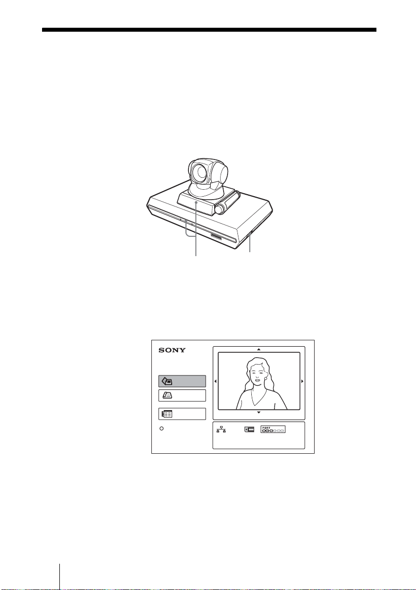
Turning the System On
1 Turn on the TV monitor.
2 Turn on the power of any other equipment to be used for the
videoconference.
3 Set the power switch on the right side of the Communication Terminal to
the on position (
@).
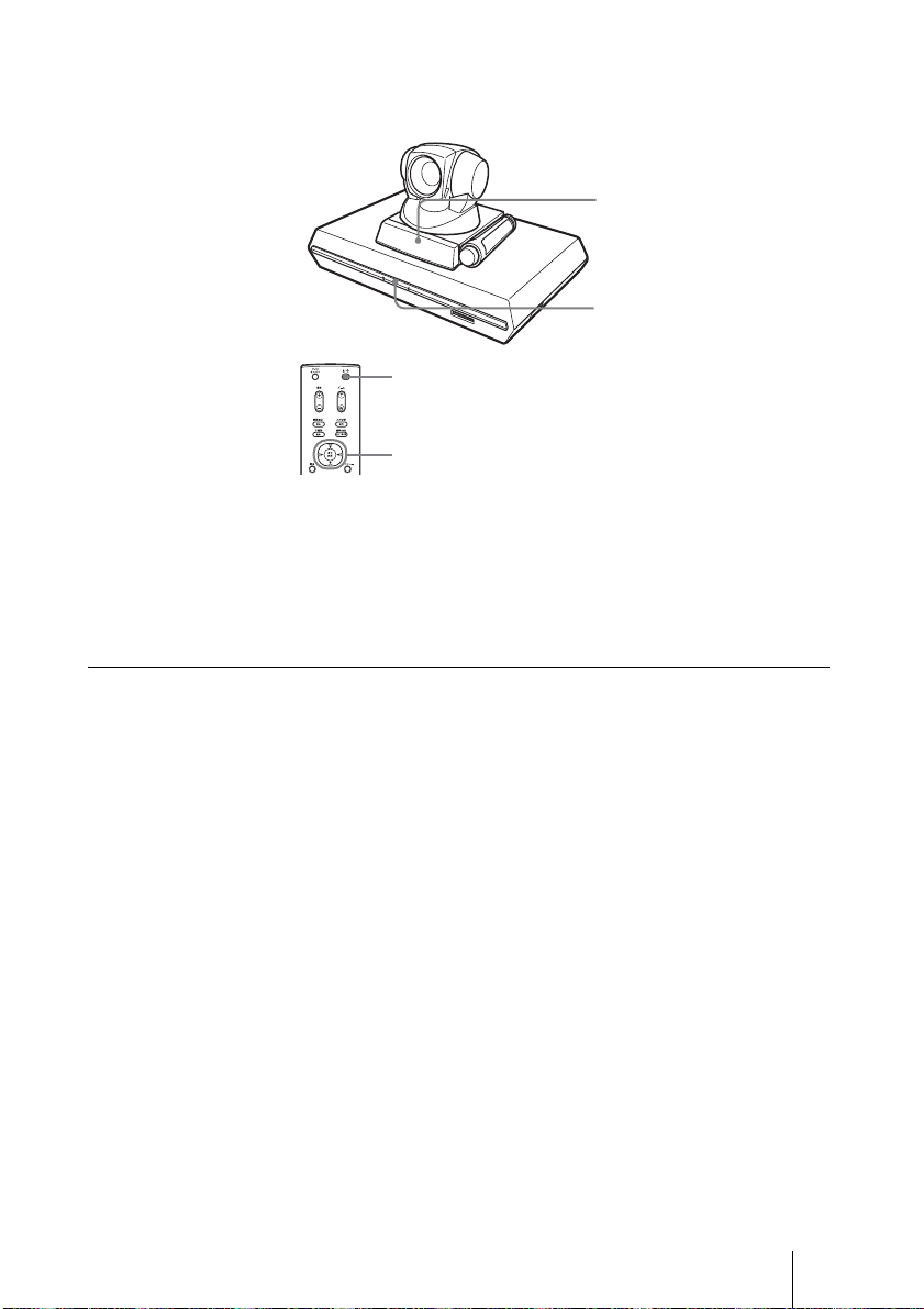
Camera Unit
Communication Terminal
POWER indicators
Power switch
The Communication Terminal turns on after a while. Three indicators on the
front of the Communication Terminal and the POWER indicator on the camera
light, then only the POWER indicators on both units remain on in green. The
launcher menu will appear on the monitor screen and the picture shot by the
local camera will also appear in the launcher menu.
Connect
Phone Book
Dial
Menu
Press to show help
*
The illustration of the launcher menu in this guide shows an example of when the
IP:0.0.0.0
Video:Main
Angle Adj.
*
ISDN:012345678912
Audio:MIC(INT)+AUX
PCS-B768 ISDN Unit is used. The ISDN port indicator differs from that of the PCSB384 ISDN Unit.
GB
6 Turning the System On
Page 29
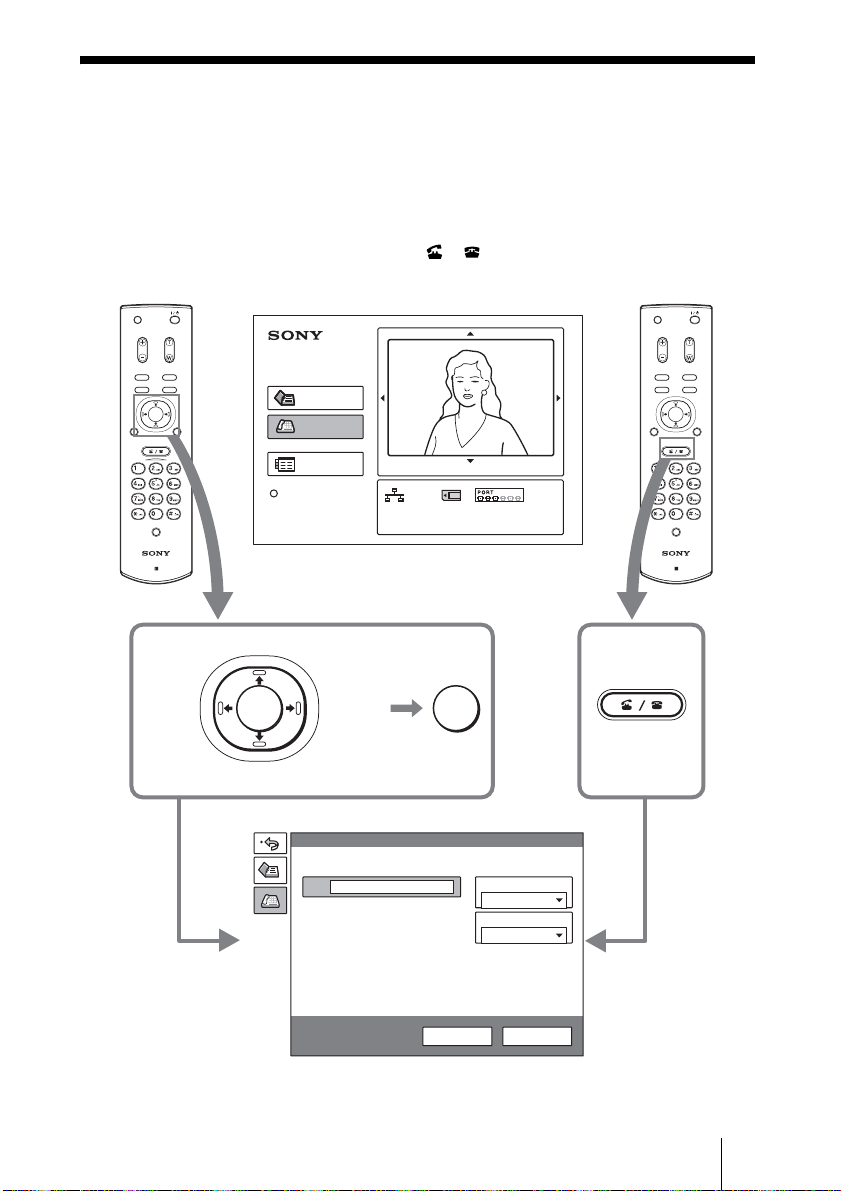
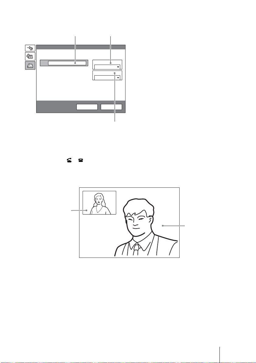
Calling a Remote Party
This guide shows you how to call a remote party not registered in the Phone
Book.
1 Press the V, v, B or b button on the Remote Commander to select “Dial”
in the launcher menu, then press the PUSH ENTER button, or press the
CONNECT/DISCONNECT ( / ) button.
The Dial menu appears on the monitor screen.
MIC
ON/OFF
VOLUME
ZOOM
MIC
ON/OFF
VOLUME
ZOOM
VIDEOINPUT
DISPLAY
SELECT
CLEAR SYMBOL
PinP FAR/NEAR
BACK
ALPHA/
SPACE
NUM
PUSH
ENTER
RETURN MENU
CONNECT/
DISCONNECT
HELP
PCS-R1
Launcher menu
Up
Left Right
PUSH
ENTER
Down
Connect
Phone Book
Dial
Menu
Press to show help
Dial
IP
A2
B1
B2
C1
C2
IP:0.0.0.0
Video:Main
Angle Adj.
ISDN:012345678912
Audio:MIC(INT)+AUX
PUSH
ENTER
Or
Line I/F
LAN
LAN Bandwidth
1024 Kbps
DISPLAY
RETURN MENU
CONNECT/
DISCONNECT
CLEAR SYMBOL
PinP FAR/NEAR
BACK
SPACE
PUSH
ENTER
CONNECT/
DISCONNECT
HELP
PCS-R1
VIDEOINPUT
SELECT
ALPHA/
NUM
More Options
Dial menu
Dial Save
Calling a Remote Party
GB
7
Page 30
2 Set up the items in the Dial menu.
Use the V, v, B or b button to select the item to be set, then press the PUSH
ENTER button.
You can use the number buttons and (dot) button to input the numerals.
CONNECT/
DISCONNECT
Up
Left Right
PUSH
ENTER
PUSH
ENTER
Down
When you connect a remote party over LAN
1 Select “Line I/F”, then select “LAN”
2 Select the IP text box, then enter the IP
3 Select “LAN Bandwidth”, then select
Dial
IP
A2
B1
B2
More Options
12
Line I/F:
LAN
LAN Bandwidth:
1024 Kbps
Dial Save
Number
buttons
HELP
PCS-R1
button
from the displayed submenu.
address of the remote party using the
number buttons and (dot) button
on the Remote Commander.
the bandwidth you are using.
GB
8 Calling a Remote Party
3
Page 31

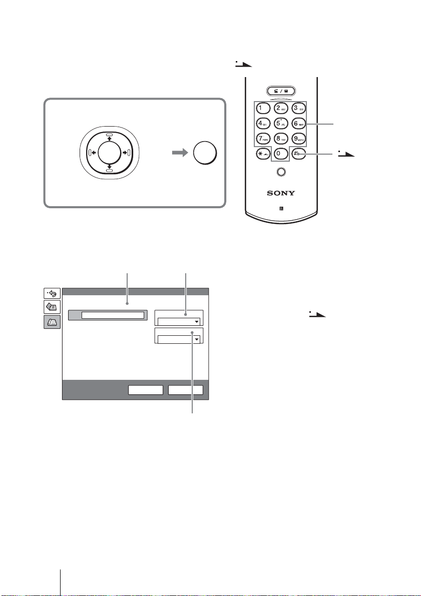
When you connect a remote party over ISDN
12
1 Select “Line I/F”, then select “ISDN”
from the displayed submenu.
Dial
2 Select the telephone number text box,
then enter the telephone number of the
A
A2
B1
B2
C1
C2
More Options
Line I/F
ISDN
Number of Lines
6B
Dial Save
remote party with the number buttons on
the Remote Commander.
3 Select “Number of Lines”, then select
the number of channels to be used when
dialing the remote party.
3
3 Use the V, v, B or b button to select “Dial” in the lower part of the Dial
menu, then press the PUSH ENTER button, or press the CONNECT/
DISCONNECT ( / ) button.
When the System connects to the remote party, the message “Meeting starts!”
is displayed and the screen turns as follows.
Local picture
Remote picture
Calling a Remote Party
GB
9
Page 32

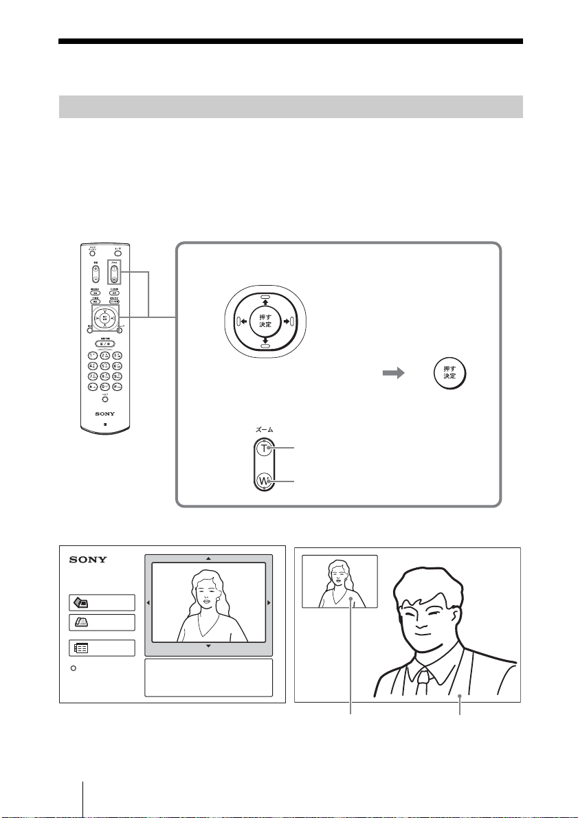
Adjusting the Picture and Sound
Adjusting the Camera Angle and Zoom
To adjust when not in communication
Use the
the launcher menu, then press the PUSH ENTER button.
Press the
button to zoom in or out.
After the adjustment, press the PUSH ENTER button.
MIC
ON/OFF
VOLUME
ZOOM
VIDEOINPUT
DISPLAY
SELECT
CLEAR SYMBOL
PinP FAR/NEAR
BACK
ALPHA/
SPACE
NUM
PUSH
PUSH
ENTER
ENTER
RETURN MENU
CONNECT/
DISCONNECT
V, v, B or b button on the Remote Commander to select the picture in
V, v, B or b button to adjust the camera angle and the ZOOM T/W
To adjust the angle
Up
Left
PUSH
ENTER
Right
Down
HELP
PCS-R1
To zoom in/out
ZOOM
to enlarge the picture
to reduce the picture
While not in communication While in communication
Connect
Phone Book
Dial
Menu
Press to show help
IP:0.0.0.0
Video:Main
Angle Adj.
ISDN:012345678912
Audio:MIC(INT)+AUX
PUSH
ENTER
Remote pictureLocal picture
GB
10 Adjusting the Picture and Sound
Page 33

To adjust when in communication
You can adjust the angle of the picture and zoom on the local site with the
and ZOOM T/W buttons on the Remote Commander.
v/B/b
Refer to the Operating Instructions to adjust the camera angle of the picture
and zoom on the remote site.
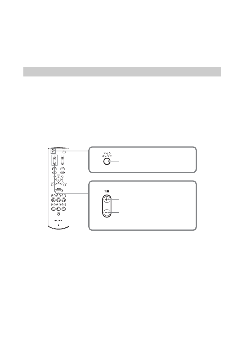
Adjusting the Volume
To adjust the volume of the sound received from the remote party
Press the VOLUME +/– button on the Remote Commander.
To cut off the sound of the local party sent to the remote party
Press the MIC ON/OFF button on the Remote Commander.
The “MIC OFF” indicator is displayed on the monitor screen. To restore the
sound, press the MIC ON/OFF button again.
MIC
ON/OFF
VOLUME
ZOOM
VIDEOINPUT
DISPLAY
SELECT
CLEAR SYMBOL
PinP FAR/NEAR
BACK
ALPHA/
SPACE
NUM
PUSH
ENTER
RETURN MENU
CONNECT/
DISCONNECT
MIC
ON/OFF
VOLUME
V/
to cut off the local sound
to increase the volume
HELP
PCS-R1
to decrease the volume
Adjusting the Picture and Sound
11
GB
Page 34

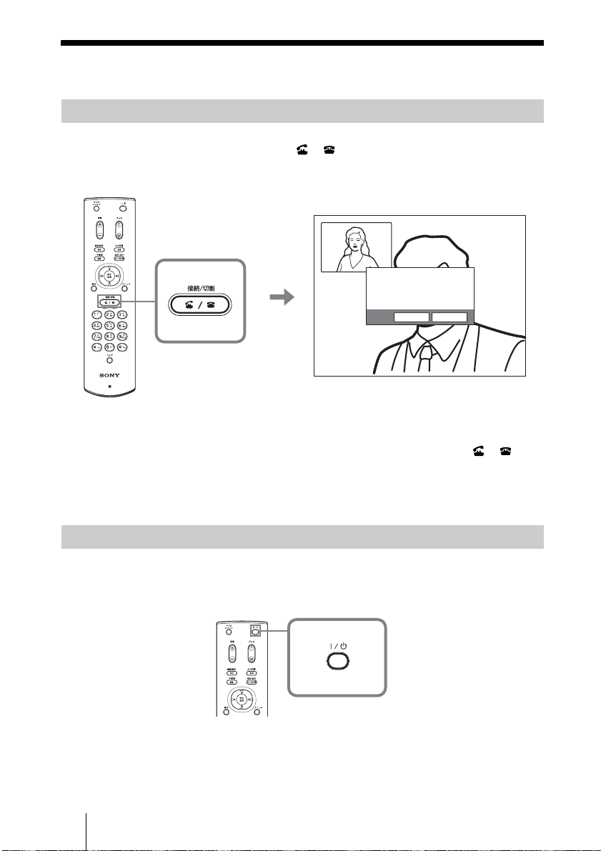
Ending the Conference
Disconnecting the Line
1 Press the CONNECT/DISCONNECT ( / ) button on the Remote
Commander.
The message “Disconnect?” appears on the monitor screen.
MIC
ON/OFF
VOLUME
ZOOM
VIDEOINPUT
DISPLAY
SELECT
CLEAR SYMBOL
PinP FAR/NEAR
BACK
ALPHA/
SPACE
NUM
PUSH
ENTER
RETURN MENU
CONNECT/
DISCONNECT
HELP
PCS-R1
2 Press the B or b button on the Remote Commander to select “OK”, then
CONNECT/
DISCONNECT
press the PUSH ENTER button, or press the CONNECT/DISCONNECT
( / ) button.
The line is disconnected and the launcher menu is restored.
Disconnect?
CancelOK
Setting the System to Standby Mode
1 Press the @/1 button on the Remote Commander.
The message “Power Off?” appears on the monitor screen.
MIC
ON/OFF
VOLUME
DISPLAY
CLEAR SYMBOL
PinP FAR/NEAR
BACK
SPACE
RETURN MENU
2 Press the B or b button on the Remote Commander to select “OK”, then
press the PUSH ENTER button, or press the
GB
12 Ending the Conference
ZOOM
VIDEOINPUT
SELECT
ALPHA/
NUM
PUSH
ENTER
@/1 button.
Page 35

The System enters standby mode, and the POWER indicator on the
Communication Terminal lights in orange.
MIC
ON/OFF
VOLUME
ZOOM
VIDEOINPUT
DISPLAY
SELECT
CLEAR SYMBOL
PinP FAR/NEAR
BACK
ALPHA/
SPACE
NUM
PUSH
ENTER
RETURN MENU
When the System is in this status, you can turn it on with the @/1 button on the
Remote Commander.
If the system receives a call, the standby mode is automatically canceled and
the system is connected.
To turn off the power
Set the power switch on the right side of the Communication Terminal to the
off position (
POWER indicator (Not lit.)
POWER indicator (Lights in orange.)
@/1 button
B/b and PUSH ENTER buttons
a), and turn off other equipment used for the videoconference.
Ending the Conference
13
GB
Page 36

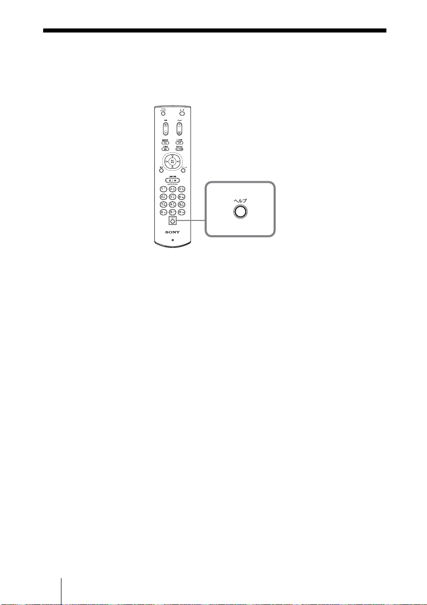
Displaying the Help
Pressing the HELP button on the Remote Commander displays a balloon help
or a help screen to guide most operations on the monitor screen.
MIC
ON/OFF
VOLUME
ZOOM
VIDEOINPUT
DISPLAY
SELECT
CLEAR SYMBOL
PinP FAR/NEAR
BACK
ALPHA/
SPACE
NUM
PUSH
ENTER
RETURN MENU
CONNECT/
DISCONNECT
HELP
PCS-R1
To hide the help guide, press the HELP button again.
HELP
GB
14 Displaying the Help
Page 37

System Components
The PCS-11/11P Video Communication System is composed of basic system
components for a basic videoconference, and optional equipment for an
enhanced videoconference.
Basic System Components
The PCS-11/11P Video Communication System is the basic system of the
PCS-11/11P Videoconferencing System. It contains the following
components:
Unit Description
PCS-P11/P11P
Communication Terminal
Contains the video codec, audio codec, echo
canceler, network interfaces and system controller.
PCS-C11/C11P Camera Unit Composed of the camera and an integrated
microphone.
PCS-R1 Remote Commander Used to operate the Communication Terminal and
Camera Unit.
PCS-AC195 AC adaptor Supplies power to the Communication Terminal.
System Components
15
GB
Page 38

Optional Equipment
TV monitor
A TV or projector, etc. is required to monitor the images for videoconferencing
system.
Unit Description
TV, Projector, etc. Used as a monitor and speakers.
Optional equipment especially designed for use with the PCS-11/11P
The following optional devices are used to enhance your videoconference.
Unit Description
PCS-B384 ISDN Unit Used to connect to an ISDN line. Up to three ISDN
lines; 6B channels usable.
PCS-B768 ISDN Unit Used to connect to an ISDN line. Up to six ISDN
PCS-A1 Microphone Omni-directional microphone that picks up sound
PCS-A300 Microphone Unidirectional microphone. It is recommended when
GB
16 System Components
lines; 12B channels usable.
relatively from all directions, allowing participants to
speak from any location. It is recommended to use in
a quiet situation.
you want to pick up the voice of a speaker directed
toward the microphone.
Page 39

Unit Description
PCS-DS150/DS150P
Document Stand
Allows transmission of pictures to the
Communication Terminal by infrared signals without
connecting a cable.
CTE-600 Communication
Transducer
Connecting cables
Use the following connecting cables to connect devices in this system.
PCS-11/11P Video Communication System
Cable Part No. Number
Camera cable (0.25 m (0.8 feet)) 1-827-376-11 1
S-video connecting cable (1.5 m (4.9 feet)) 1-776-078-42 1
Audio connecting cable (1 m (3.3 feet)) 1-765-258-31 1
Camera cable
S-video connecting cable
Integrated microphone/speaker system suitable for
remote communication. The uni-directional
microphones pick up clear voice with minimum
background noise.
Moreover, the omni-directional speaker outputs
sound equally in all directions.
Audio connecting cable
System Components
17
GB
Page 40

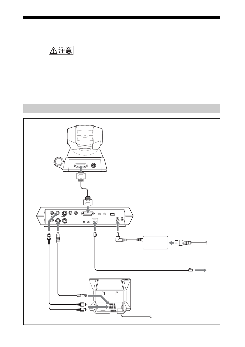
System Connections
This section describes the typical system connections.
Notes
• Be sure to turn off all the equipment before making any connections.
• Do not connect/disconnect the camera cable with the power on. Doing so may damage
the Camera Unit or Communication Terminal.
• For safety, do not connect the 100BASE-TX/10BASE-T connector to a network that
applies an excess voltage via the 100BASE-TX/10BASE-T connector.
System Connection via a LAN
PCS-C11/C11P Camera Unit
TERMINAL VISCA OUT
to TERMINAL
PCS-P11/P11P
Communication
Terminal
AUDIO OUT
(MIXED)
VIDEO OUT
MAIN–MONITOR–SUB
AUX
to AUDIO
OUT
Audio
connecting
cable*
* supplied
** not supplied
GB
18 System Connections
AUDIO IN
AUX1–
VIDEO IN
–AUX2
to VIDEO
OUT
MONITOR
MAIN
S-video
connecting
cable*
to S-video
input
to audio input
Camera cable*
to CAMERA UNIT
CAMERA UNIT MIC
(PLUG IN POWER)
1 2
100BASE-TX
10BASE-T
IR OUT
12
to 100BASE-TX/
10BASE-T
ISDN UNIT
DC 19.5V
to DC19.5V
PCS-AC195
AC adaptor
UTP cable (category 5, straight)**
TV monitor**
to a wall outlet
Power cord*
to a wall outlet
to LAN
Page 41

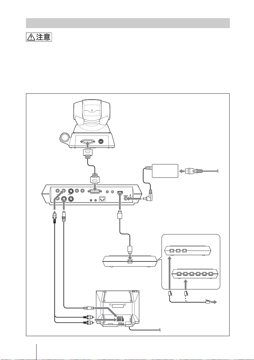
System Connection via an ISDN
Notes
• Do not connect/disconnect the camera cable or the interface cable with the power on.
Doing so may damage the Camera Unit, Communication Terminal or ISDN Unit.
• Used with the ISDN Unit for the first time, the Communication Terminal may
upgrade the software of the ISDN Unit. While the upgrading message is displayed on
the monitor screen, be sure not to turn off the Communication Terminal. Doing so
may cause malfunction of the system.
PCS-C11/C11P Camera Unit
TERMINAL VISCA OUT
to AUDIO
OUT
Audio
connecting
cable*
PCS-P11/P11P
Communication
Terminal
AUDIO OUT
AUX1–
VIDEO IN
(MIXED)
VIDEO OUT
MAIN–MONITOR–SUB
AUX
to VIDEO
OUT
MONITOR
MAIN
S-video
connecting
cable*
to S-video
to TERMINAL
Camera cable*
to CAMERA UNIT
AUDIO IN
–AUX2
CAMERA UNIT MIC
100BASE-TX
IR OUT
12
10BASE-T
RGB OUT DSB
to ISDN
Interface cable
(supplied with the
PCS-B384/B768)
TV monitor**
input
(PLUG IN POWER)
1 2
UNIT
ISDN UNIT
DC 19.5V
WHITE
BOARD
to DC19.5V
to
TERMINAL
to ISDN 1-3
PCS-AC195
AC adaptor
ISDN Unit**
PCS-B384
123
PCS-B768
ISDN modular
cable**
Power cord*
to a wall outlet
123 4 56
to ISDN 1-6
* supplied
** not supplied
to audio input
to a wall outlet
System Connections
19
GB
Page 42

Specifications
PCS-P11/P11P Communication
Terminal
This unit is compliant with ITU-T
Recommendations H.320 and H.323.
Motion picture
Operating bandwidth
64 Kbps to 1024 Kbps (standard,
LAN connection)
56 Kbps to 384 Kbps (when
installing the PCS-B384, ISDN
connection)
56 Kbps to 768 Kbps (when
installing the PCS-B768, ISDN
connection)
Coding H.261/H.263/H.263+/H.263++/
H.264 (ITU-T
Recommendation)
Picture elements
CIF: 352 pixels × 288 lines
QCIF: 176 pixels × 144 lines
Color system
NTSC (PCS-P11)
PAL (PCS-P11P)
Capable of connection between
both color systems
Still Picture
Pixels 704 pixels × 480 lines (PCS-P11)
704 pixels × 576 lines (PCS-P11P)
Encoding H.261 (ITU-T Recommendation)
Annex. D (4CIF)
H.263 (special format of this
system)
Sound
Bandwidth 7 kHz (G.722 compliant with ITU-
T Recommendation)
3.4 kHz (G.711/G.728 compliant
with ITU-T Recommendation)
Transmission rate
56 Kbps, 64 Kbps (G.711
compliant with ITU-T
Recommendation)
48 Kbps, 56 Kbps, 64 Kbps (G. 722
compliant with ITU-T
Recommendation)
16 Kbps (G.728 compliant with
ITU-T Recommendation)
Network
Multiplexing
Frame format
Interface LAN (standard), 64 Kbps to 1024
Data transmission rate
LAN protocol supported
Video, audio, data
H.221 (compliant with ITU-T
Recommendation)
Kbps
ISDN (BRI), up to 3 lines (when
installing the PCS-B384), up to
6 lines (when installing the
PCS-B768)
LSD 1.2 Kbps, 4.8 Kbps, 6.4 Kbps
MLP 6.4 Kbps, 24 Kbps, 32 Kbps
HMLP 62.4 Kbps, 64 Kbps, 128
Kbps
HTTP
FTP
Telnet
RTP/RTCP
TCP/UDP
Remote control
Far end camera control
Data transfer
H.281 (compliant with ITU-T
Recommendation)
T.120 (compliant with ITU-T
Recommendation)
General
Power requirements
Power consumption
Operating temperature
Operating humidity
Storage temperature
Storage humidity
Dimensions 258 × 54 × 171 mm (w/h/d)
Mass Approx. 1.3 kg (2 lb 14 oz)
Supplied accessories
19.5 V
3.0 A
5°C to 35°C (41°F to 94°F)
20% to 80%
–20°C to +60°C (–4°F to +140°F)
20% to 80% (no condensation)
1
/4 × 2 1/4 × 6 3/4 inches) (not
(10
including the projected
Remote Commander PCS-R1 (1)
Size AA (R6) batteries for Remote
Commander (2)
IR repeater (2)
Camera cable (0.25 m, 0.8 ft) (1)
S-video connecting cable (1.5 m,
4.9 ft) (1)
parts)
GB
20 Specifications
Page 43

Audio connecting cable (1 m, 3.3
ft) (1)
AC adaptor PCS-AC195 (1)
Power cord (1)
21-pin adaptor (1) (PCS-P11P
only)
Velcro (3 for the Camera Unit, 2
for the Communication
Terminal)
CD-ROM (1)
Operation guide (1)
Warranty booklet (1)
PCS-C11/C11P Camera Unit
Video signal
Image device
Lens f = 3.1 to 31 mm, F 1.8 to 2.9,
Focal distance
Minimum illumination
Illumination range
Horizontal resolution
Pan/tilt action
Dimension 147 × 130 × 138 mm (w/h/d) (5
Mass Approx. 1.1 kg (2 lb 7 oz)
NTSC color, EIA standards (PCS-
C11)
PAL color, CCIR standards (PCS-
C11P)
1/4 type CCD (Charge Coupled
Device)
Approx. 410 000 p ixels (Effective:
approx. 380 000 pixels) (PCS-
C11)
Approx. 470 000 p ixels (Effective:
approx. 440 000 pixels) (PCS-
C11P)
Horizontal angle 6.6° to 65°
100 (WIDE) to 600 (TELE) mm
3.5 lux at F 1.8/50 IRE
3.5 lux to 100 000 lux
470 TV lines (PCS-C11)
450 TV lines (PCS-C11P)
Horizontal ±100°
Vertical ±25°
1
/8 × 5 1/2 inches) (not
× 5
including the projected parts)
Microphone
Frequency range
Directional characteristic
18 kHz
Narrow-angle directional
PCS-R1 Remote Commander
Signal format
Infrared SIRCS
Control DC 3V using two size AA (R6)
batteries
Dimensions 50 × 24 × 197 mm (w/h/d) (2 ×
31
/32 × 7 7/8 inches) (not inc luding
the projected parts)
Mass Approx. 140 g (4 oz) (including
batteries)
PCS-AC195 AC Adaptor
Power requirements
Output 19.5 V, 4.1A
Operating temperature
Operating humidity
Storage temperature
Storage humidity
Dimensions 63 × 31 × 140 mm (w/h/d) (2
Mass Approx. 410 g (14 oz)
100 to 240V AC, 50/60 Hz, 1.3 A
to 0.6 A
5°C to 35°C (41°F to 94°F)
20% to 80%
–20°C to +60°C (–4°F to +140°F)
20% to 80% (no condensation)
1
/4 × 5 5/8 inches)
1
PCS-A1 Microphone (Optional)
Bandwidth 13 kHz
Directional characteristic
Omnidirectional
Dimensions 74 × 16 × 93 mm (w/h/d)
21
/32 × 3 3/4 inches)
(3 ×
Mass Approx. 170 g (6 oz)
Power Plug in power
PCS-A300 Microphone (Optional)
Bandwidth 13 kHz
Directional characteristic
Unidirectional
Dimension 68 × 16 × 96 mm (w/h/d) (2
7
Mass Approx. 200 g (7 oz)
/8
Power Plug in power
21
/32 × 3 7/8 inches)
PCS-B384 ISDN Unit (Optional)
Power requirements
Power consumption
Operating temperature
Operating humidity
Storage temperature
Storage humidity
19.5 V
0.3 A
5°C to 35°C (41°F to 94°F)
20% to 80%
–20°C to +60°C (–4°F to +140°F)
3
/4 ×
1
/2 ×
Specifications
21
GB
Page 44

Dimensions 165 × 34 × 127 mm (w/h/d) (6
3
/8 × 5 inches) (not including
1
the projected parts)
Mass Approx. 400 g (14 oz)
Supplied accessories
Interface cable (5 m, 16.4 ft) (1)
Operating Instructions (1)
Warranty booklet (1)
PCS-B768 ISDN Unit (Optional)
20% to 80% (no condensation)
Power requirements
Power consumption
Operating temperature
Operating humidity
Storage temperature
Storage humidity
Dimensions 165 × 34 × 127 mm (w/h/d) (6
Mass Approx. 400 g (14 oz)
Supplied accessories
19.5 V
0.5 A
5°C to 35°C (41°F to 94°F)
20% to 80%
–20°C to +60°C (–4°F to +140°F)
20% to 80% (no condensation)
3
/8 × 5 inches) (not including
1
the projected parts)
Interface cable (5 m, 16.4 ft) (1)
Operating Instructions (1)
Warranty booklet (1)
1
1
/2 ×
/2 ×
Design and specifications are subject to change
without notice.
GB
22 Specifications
Page 45

Specifications
23
GB
Page 46

AVERTISSEMENT
Afin d’éviter tout risque d’incendie
ou d’électrocution, ne pas exposer
cet appareil à la pluie ou à
l’humidité.
Afin d’écarter tout risque
d’électrocution, garder le coffret
fermé. Ne confier l’entretien de
l’appareil qu’à un technicien
qualifié.
AVERTISSEMENT
Cet appareil n’est pas équipé d’un
commutateur d’alimentation.
Lors de l’installation de l’appareil,
incorporez un dispositif de coupure facile
d’accès dans le câblage fixe ou branchez le
cordon d’alimentation dans une prise murale
facilement accessible située à proximité de
l’appareil.
En cas d’anomalie pendant le
fonctionnement de l’appareil, mettez
l’appareil hors tension au moyen du
dispositif de coupure ou débranchez le
cordon d’alimentation.
IMPORTANT
La plaquette signalétique est située sur la
face inférieure de l’appareil.
Voor de klanten in Nederland
Dit apparaat bevat een vast ingebouwde
batterij die niet vervangen hoeft te worden
tijdens de levensduur van het apparaat.
Raadpleeg uw leverancier indien de batterij
toch vervangen moet worden.
De batterij mag alleen vervangen worden
door vakbekwaam servicepersoneel.
Gooi de batterij niet weg maar lever deze in
als klein chemisch afval (KCA).
Lever het apparaat aan het einde van de
levensduur in voor recycling, de batterij zal
dan op correcte wijze verwerkt worden.
Si vous vous débarrassez de l’appareil,
consultez votre revendeur Sony le plus
proche. La batterie intégrée doit être traitée
comme un déchet de l’industrie chimique.
Pour les utilisateurs au Canada
Cet appareil numérique de la classe A est
conforme à la norme NMB-003 du Canada.
Ce mode d’emploi part du principe que des
lignes RNIS sont utilisées pour la
vidéoconférence, mais il couvre également
des lignes qui ne sont pas RNIS. Si vous
utilisez des lignes RNIS, demandez des
informations complémentaires à votre
revendeur Sony.
• Le service RNIS n’est pas disponible
dans certains pays.
FR
AVERTISSEMENT
2
Page 47

En cas d’utilisation
du système pour la
première fois
Ce guide décrit brièvement les principales
opérations nécessaires pour exécuter une
vidéoconférence point à point au moyen
du système de communication vidéo
PCS-11/11P. Vous apprendrez à exécuter
une conférence quotidienne du début à la fin.
Pour les opérations plus détaillées et les
divers réglages requis pour une conférence,
reportez-vous au Mode d’emploi contenu
dans le CD-ROM fourni.
Pour accéder à la page de votre choix,
cliquez sur un élément de la table des
matières.
Pour installer Adobe Acrobat
Reader 5.0 (E)
Pour installer Adobe Acrobat Reader 5.0 (E)
dans votre ordinateur, vous devez disposer
du matériel et des logiciels suivants :
• Un ordinateur avec processeur Intel
Pentium
• Microsoft
Windows Millennium, Windows NT
4.0 Service Pack 5 ou Windows 2000 et
ultérieur
• RAM de 64 Mo ou plus
• Espace disque libre de 70 Mo ou plus
®
ou 100% compatible
®
Windows
®**
98 SE,
®
®**
A propos du mode d’emploi
Le mode d’emploi du système est enregistré
au format PDF dans le CD-ROM fourni. Un
message demandant d’utiliser Adobe
®*
Acrobat
l’écran. Si Adobe Acrobat Reader n’est pas
installé sur votre ordinateur, vous pouvez
télécharger la version la plus récente des
sites Web ci-dessous.
Reader pour le lire s’affichera à
Comment lire le mode d’emploi
®
Vous pouvez vous procurer la version la plus
récente de Adobe Acrobat Reader,
gratuitement, auprès des sites Web suivants.
Version nord-américaine :
http://www.adobe.com/products/acrobat/
readstep.html
Version européenne :
http://www.adobe.com/products/acrobat/
acrrcenteuro.html
Version japonaise :
http://www.adobe.co.jp/products/acrobat/
readstep.html
1 Insérez le CD-ROM fourni intitulé
« Manuals for Video Communication
System » dans le lecteur de CD-ROM
de votre ordinateur.
Après quelques instants, une fenêtre
s’ouvre, affichant les fichiers enregistrés
sur le CD-ROM.
2 Cliquez deux fois sur le fichier PDF
intitulé « French ».
Adobe Acrobat Reader démarre, puis
affiche la page de couverture du mode
d’emploi.
....................................................................................................................................................
* Adobe et Acrobat sont des marques commerciales d’Adobe Systems, Incorporated.
** Windows et Windows NT sont des marques commerciales d’U.S. Microsoft Corporation aux
Etats-Unis et dans les autres pays.
FR
En cas d’utilisation du système pour la première fois
FR
3
Page 48

Table de matières
Activation du système ........................5
Pour appeler un correspondant ...........6
Réglage de l’image et du son .............9
Réglage de l’angle de la caméra et
du zoom .............................9
Réglage du volume .....................10
Pour terminer la conférence .............11
Déconnexion de la ligne .............11
Réglage du système en mode de
veille ................................11
Affichage de l’aide ...........................13
Composants du système ...................14
Composants du système de base 14
Equipement en option .................15
Connexions système .........................18
Connexion système via un réseau
LAN ................................18
Connexion système via un réseau
RNIS ...............................19
Spécifications ...................................20
Le CD-ROM fourni contient le mode
d’emploi qui donne des informations plus
détaillées sur ce système. Veuillez lire le
mode d’emploi ainsi que le guide
d’utilisation.
FR
4 Table de matières
Page 49

Activation du système
1 Mettez sous tension le moniteur de télévision.
2 Mettez sous tension le ou les autres appareils à utiliser pour la
vidéoconférence.
3 Placez le commutateur d’alimentation sur le côté droit du terminal de
communication sur la position de marche (
@).
Caméra
Terminal de communication
Indicateurs POWER
Commutateur d’alimentation
Le terminal de communication se met sous tension après quelques instants.
Trois indicateurs sur la face avant du terminal de communication et l’indicateur
POWER sur la caméra s’allument, puis seuls les indicateurs POWER sur les
deux appareils restent allumés en vert. Le menu de démarrage s’affiche sur
l’écran du moniteur et l’image prise par la caméra locale apparaît aussi dans le
menu de démarrage..
Connecter
Annuaire
Appel
Menu
Montrer Aide
*
Chaque fois que le menu de démarrage est illustré dans ce guide, l’unité RNIS
IP:0.0.0.0
Video:Main
Régl. angle
*
ISDN:012345678912
Audio:MIC(INT)+AUX
PCS-B768 est utilisée. L’indicateur de port RNIS est différent de celui de l’exemple
avec utilisation de l’unité RNIS PCS-B384.
Activation du système
FR
5
Page 50

Pour appeler un correspondant
Cette section vous montre comment appeler un correspondant non enregistré
dans l’annuaire.
1 Appuyez sur la touche V, v, B ou b de la télécommande pour sélectionner
« Appel » dans le menu de démarrage, puis sur la touche PUSH ENTER,
ou appuyez sur la touche CONNECT/DISCONNECT ( / ).
Le menu Appel s’affiche sur l’écran du moniteur.
MIC
ON/OFF
VOLUME
ZOOM
MIC
ON/OFF
VOLUME
ZOOM
VIDEOINPUT
DISPLAY
SELECT
CLEAR SYMBOL
PinP FAR/NEAR
BACK
SPACE
PUSH
ENTER
RETURN MENU
CONNECT/
DISCONNECT
ALPHA/
NUM
Connecter
Annuaire
Appel
Menu
Montrer Aide
HELP
PCS-R1
Menu de démarrage
Haut
Gauche Droit
PUSH
ENTER
Bas
Appel
IP
A2
B1
B2
C1
C2
IP:0.0.0.0
Video:Main
ISDN:012345678912
Audio:MIC(INT)+AUX
PUSH
ENTER
Interface réseau
LAN
Bande passante LAN
1024 Kbps
Régl. angle
Ou
DISPLAY
RETURN MENU
CONNECT/
DISCONNECT
CLEAR SYMBOL
PinP FAR/NEAR
BACK
SPACE
PUSH
ENTER
CONNECT/
DISCONNECT
HELP
PCS-R1
VIDEOINPUT
SELECT
ALPHA/
NUM
Menu Appel
FR
6 Pour appeler un correspondant
More Options
Appel Enregistrer
Page 51

2 Configurez les éléments dans le menu Appel.
Utilisez la touche V, v, B ou b pour sélectionner l’élément à régler, puis
appuyez sur la touche PUSH ENTER.
Vous pouvez utiliser les touches numériques et la touche (point) pour
entrer les chiffres.
CONNECT/
DISCONNECT
Haut
Gauche Droit
PUSH
ENTER
Bas
Si vous établissez une connexion avec un correspondant via un
réseau LAN
Appel
IP
A2
B1
B2
C1
C2
More Options
Appel Enregistrer
PUSH
ENTER
12
Interface réseau
LAN
Bande passante LAN
1024 Kbps
Touches
numériques
Touche
HELP
PCS-R1
1 Sélectionnez « Interface réseau», puis
« LAN » dans le sous-menu affiché.
2 Sélectionnez la zone de texte IP, puis
entrez l’adresse IP du correspondant au
moyen des touches numériques et de la
touche (point) de la
télécommande.
3 Sélectionnez « Bande passante LAN »,
puis la bande passante utilisée.
3
FR
Pour appeler un correspondant
7
Page 52

Si vous établissez une connexion avec un correspondant via une
connexion RNIS
12
1 Sélectionnez « Interface réseau », puis
sélectionnez « RNIS » dans le
Appel
sous-menu affiché.
2 Sélectionnez la zone de texte de numéro
A
Interface réseau
RNIS
Débit
384 K
de téléphone, puis entrez le numéro de
téléphone du correspondant à l’aide des
touches numériques de la
télécommande.
3 Sélectionnez « Débit », puis
sélectionnez le débit à utiliser pour
appeler le correspondant.
More Options
Appel Enregistrer
3
3 Utilisez la touche V, v, B ou b pour sélectionner « Appel » dans la partie
inférieure du menu Appel, puis appuyez sur la touche PUSH ENTER, ou
appuyez sur la touche CONNECT/DISCONNECT ( / ).
Une fois la connexion avec le correspondant établie, le message « Début de la
conférence. » s’affiche et l’écran change comme suit.
Image locale
FR
8 Pour appeler un correspondant
Image distante
Page 53

Réglage de l’image et du son
Réglage de l’angle de la caméra et du zoom
Réglages en dehors d’une communication
Utilisez la touche
dans le menu de démarrage, puis appuyez sur la touche PUSH ENTER.
Appuyez sur la touche
ZOOM T/W pour faire un zoom avant ou arrière.
Une fois le réglage effectué, appuyez sur la touche PUSH ENTER.
MIC
ON/OFF
VOLUME
ZOOM
VIDEOINPUT
DISPLAY
SELECT
CLEAR SYMBOL
PinP FAR/NEAR
BACK
ALPHA/
SPACE
NUM
PUSH
PUSH
ENTER
ENTER
RETURN MENU
CONNECT/
DISCONNECT
V, v, B ou b de la télécommande pour sélectionner l’image
V, v, B ou b pour régler l’angle de la caméra et la touche
Pour régler l’angle
Haut
Gauche
PUSH
ENTER
Droit
Bas
HELP
PCS-R1
Pour effectuer un zoom avant ou arrière
ZOOM
pour agrandir l’image
pour réduire l’image
En dehors d’une communication Pendant une communication
Connecter
Annuaire
Appel
Menu
Montrer Aide
IP:0.0.0.0
Video:Main
Régl. angle
ISDN:012345678912
Audio:MIC(INT)+AUX
PUSH
ENTER
Image distanteImage locale
Réglage de l’image et du son
FR
9
Page 54

Réglage pendant une communication
Vous pouvez régler l’angle de l’image et le zoom sur le site local à l’aide des
touches
V/v/B/b et ZOOM T/W de la télécommande.
Reportez-vous au mode d’emploi pour régler l’angle de prise de vue et le zoom
sur le site distant.
Réglage du volume
Pour régler le volume du son reçu du correspondant
Appuyez sur la touche VOLUME +/– de la télécommande.
Pour couper le son du site local envoyé au correspondant
Appuyez sur la touche MIC ON/OFF de la télécommande.
L’indicateur « MIC OFF » s’affiche sur l’écran du moniteur. Pour rétablir le
son, appuyez une nouvelle fois sur la touche MIC ON/OFF.
MIC
ON/OFF
VOLUME
ZOOM
VIDEOINPUT
DISPLAY
SELECT
CLEAR SYMBOL
PinP FAR/NEAR
BACK
ALPHA/
SPACE
NUM
PUSH
ENTER
RETURN MENU
CONNECT/
DISCONNECT
MIC
ON/OFF
VOLUME
pour couper le son local
pour augmenter le volume
HELP
PCS-R1
FR
10 Réglage de l’image et du son
pour diminuer le volume
Page 55

Pour terminer la conférence
Déconnexion de la ligne
1 Appuyez sur la touche CONNECT/DISCONNECT ( / ) de la
télécommande.
Le message « Déconnexion ? » s’affiche sur l’écran du moniteur.
MIC
ON/OFF
VOLUME
ZOOM
VIDEOINPUT
DISPLAY
SELECT
CLEAR SYMBOL
PinP FAR/NEAR
BACK
ALPHA/
SPACE
NUM
PUSH
ENTER
RETURN MENU
CONNECT/
DISCONNECT
HELP
PCS-R1
2 Appuyez sur la touche B ou b de la télécommande pour sélectionner
CONNECT/
DISCONNECT
Déconnexion?
« OK », puis sur la touche PUSH ENTER, ou appuyez sur la touche
CONNECT/DISCONNECT ( / ).
La ligne est débranchée et le menu de démarrage est rétabli.
AnnulerOK
Réglage du système en mode de veille
1 Appuyez sur la touche @/1 de la télécommande.
Le message « Mise hors tension ? » s’affiche sur l’écran du moniteur.
MIC
ON/OFF
VOLUME
ZOOM
VIDEOINPUT
DISPLAY
SELECT
CLEAR SYMBOL
PinP FAR/NEAR
BACK
ALPHA/
SPACE
NUM
PUSH
ENTER
RETURN MENU
Pour terminer la conférence
11
FR
Page 56

2 Appuyez sur la touche B ou b de la télécommande pour sélectionner
« OK », puis sur la touche PUSH ENTER, ou appuyez sur la touche
Le système passe en mode de veille et l’indicateur POWER sur le terminal de
communication s’allume en orange.
MIC
ON/OFF
VOLUME
DISPLAY
CLEAR SYMBOL
PinP FAR/NEAR
BACK
SPACE
PUSH
ENTER
RETURN MENU
Lorsque le système se trouve dans ce mode, vous pouvez l’activer au moyen de
la touche @/1 de la télécommande.
Lorsque le système reçoit un appel, le mode de veille est automatiquement
annulé et le système est connecté.
Pour le mettre hors tension
Réglez le commutateur d’alimentation sur le côté droit du terminal de
communication sur la position Arrêt (
appareils utilisés pour la vidéoconférence.
Touche
ZOOM
VIDEOINPUT
SELECT
ALPHA/
NUM
Touches B/b et PUSH ENTER
@/1.
Indicateur POWER (éteint)
Indicateur POWER (allumé en orange)
@/1
a), et mettez hors tension le ou les autres
FR
12 Pour terminer la conférence
Page 57

Affichage de l’aide
Appuyez sur la touche HELP de la télécommande pour afficher une bulle ou
un écran d’aide afin d’obtenir des instructions de guidage concernant la plupart
des opérations sur l’écran du moniteur.
MIC
ON/OFF
VOLUME
DISPLAY
CLEAR SYMBOL
PinP FAR/NEAR
BACK
SPACE
PUSH
ENTER
RETURN MENU
CONNECT/
DISCONNECT
HELP
PCS-R1
Pour cacher le guide d’aide, appuyez une nouvelle fois sur la touche HELP.
ZOOM
VIDEOINPUT
SELECT
ALPHA/
NUM
HELP
Affichage de l’aide
13
FR
Page 58

Composants du système
Le système de communication vidéo PCS-11/11P est constitué des
composants système nécessaires pour une vidéoconférence de base et
d’équipements en option pour une vidéoconférence avancée.
Composants du système de base
Le système de communication vidéo PCS-11/11P est le système de base du
système de vidéoconférence PCS-11/11P. Il est constitué des éléments
suivants :
Unité Description
Terminal de communication
PCS-P11/P11P
Caméra PCS-C11/C11P Composée d’une caméra et d’un microphone intégré.
Comprend le codec vidéo, le codec audio,
l’éliminateur d’écho, les interfaces réseau et le
contrôleur système.
Télécommande PCS-R1 Permet de commander le terminal de communication
Adaptateur secteur
PCS-AC195
FR
14 Composants du système
et la caméra.
Assure l’alimentation électrique du terminal de
communication.
Page 59

Equipement en option
Moniteur de télévision
Un téléviseur, un projecteur, etc., est nécessaire pour contrôler les images du
système de vidéoconférence.
Unité Description
Téléviseur, projecteur, etc. Utilisé comme moniteur et comme haut-parleur.
Equipement en option conçu spécialement pour être utilisé avec
le PCS-11/11P
Les périphériques en option suivants vous permettent d’améliorer vos
vidéoconférences.
Unité Description
Unité RNIS PCS-B384 Permet de connecter une ligne RNIS. Possibilité
d'utiliser jusqu'à trois lignes RNIS et jusqu'à
6 canaux B.
Unité RNIS PCS-B768 Permet de connecter une ligne RNIS. Possibilité
d’utiliser jusqu’à six lignes RNIS et jusqu’à
12 canaux B.
Microphone PCS-A1 Microphone omnidirectionnel (capable de capter le
son dans toutes les directions) permettant aux
participants de parler à partir de n’importe quelle
position. Il est recommandé de l’utiliser dans un
environnement calme.
Composants du système
15
FR
Page 60

Unité Description
Microphone PCS-A300 Microphone unidirectionnel. Recommandé pour
capter la voix d’une personne orientée vers le
microphone.
Support Document
PCS-DS150/DS150P
Transducteur de
communication CTE-600
Permet de transmettre des images vers le terminal de
communication à l’aide de signaux infrarouges sans
qu’il soit nécessaire de connecter un câble.
Système de microphone/haut-parleur intégré pour la
communication à distance. Les microphones
unidirectionnels captent une voix claire avec un bruit
de fond minimum.
En outre, le haut-parleur omnidirectionnel diffuse le
son de manière uniforme dans toutes les directions.
FR
16 Composants du système
Page 61

Câbles de connexion
Utilisez les câbles de connexion suivants pour connecter les appareils au
système.
PCS-11/11P Video Communication System
Câble Référence de pièce Quantité
Câble de caméra (0,25 m (0,8 pied)) 1-827-376-11 1
Câble de connexion S-vidéo (1,5 m (4,9 pieds)) 1-776-078-42 1
Câble de connexion audio (1 m (3,3 pieds)) 1-765-258-31 1
Câble de caméra
Câble de connexion S-vidéo
Câble de connexion audio
Composants du système
17
FR
Page 62

Connexions système
Cette section décrit les connexions système types.
Remarques
• Mettez tous les appareils hors tension avant d’établir quelque connexion que ce soit.
• Ne branchez/débranchez pas le câble de caméra lorsque le système est sous tension.
Risque d’endommager la caméra ou le terminal de communication.
• Pour des raisons de sécurité, veillez à ne pas raccorder le connecteur 100BASE-TX/
10BASE-T à un réseau susceptible d’envoyer une tension excessive.
Connexion système via un réseau LAN
Caméra PCS-C11/C11P
TERMINAL VISCA OUT
vers TERMINAL
Terminal de
communication
PCS-P11/P11P
AUDIO OUT
(MIXED)
VIDEO OUT
MAIN–MONITOR–SUB
AUX
vers
AUDIO
OUT
Câble de
raccordement
audio*
*fourni
** non fourni
FR
18 Connexions système
AUDIO IN
AUX1–
VIDEO IN
–AUX2
12
vers
VIDEO OUT
MONITOR
MAIN
Câble de
raccordement
S-vidéo*
vers l’entrée
S-vidéo
vers l’entrée
audio
Câble de caméra*
vers CAMERA UNIT
CAMERA UNIT MIC
(PLUG IN POWER)
1 2
100BASE-TX
10BASE-T
IR OUT
vers
100BASE-TX/
10BASE-T
Câble UTP (catégorie 5, droit)**
ISDN UNIT
DC 19.5V
vers DC19.5V
Adaptateur secteur
PCS-AC195
Moniteur de
télévision**
vers une prise murale
Cordon
d’alimentation*
vers une prise
murale
vers LAN
Page 63

Connexion système via un réseau RNIS
Remarques
• Ne branchez/débranchez pas le câble de caméra ou le câble d’interface lorsque
l’appareil est sous tension. Risque d’endommager la caméra, le terminal de
communication ou l’unité RNIS.
• Lorsqu’il est utilisé pour la première fois avec l’unité RNIS, le terminal de
communication peut automatiquement mettre à jour le logiciel de l’unité RNIS. Tant
que le message de mise à jour est affiché sur l’écran du moniteur, veillez à ne pas
mettre le terminal de communication hors tension. Risque de provoquer un mauvais
fonctionnement du système.
Caméra PCS-C11/C11P
TERMINAL VISCA OUT
vers
AUDIO
OUT
Câble de
raccordement
audio*
Terminal de
communication
PCS-P11/P11P
AUDIO OUT
AUX1–
VIDEO IN
(MIXED)
VIDEO OUT
AUX
MAIN–MONITOR–SUB
vers
VIDEO OUT
MONITOR
MAIN
Câble de
raccordement
S-vidéo*
vers l’entrée
vers TERMINAL
Câble de caméra*
vers
CAMERA UNIT
AUDIO IN
–AUX2
CAMERA UNIT MIC
100BASE-TX
IR OUT
12
10BASE-T
RGB OUT DSB
ISDN
Câble d’interface
(fourni avec l’unité
PCS-B384/B768)
Moniteur de télévision**
S-vidéo
(PLUG IN POWER)
1 2
vers
UNIT
ISDN UNIT
DC 19.5V
WHITE
BOARD
Adaptateur
secteur
PCS-AC195
vers DC19.5V
vers
TERMINAL
ISDN 1-3
Unité RNIS**
PCS-B384
123
PCS-B768
vers
Câble modulaire
RNIS**
Cordon
d’alimentation*
vers une prise
murale
123 4 56
vers ISDN 1-6
* fourni
** non fourni
vers l’entrée
audio
vers une prise murale
Connexions système
19
FR
Page 64

Spécifications
Terminal de communication
PCS-P11/P11P
Cet appareil est conforme aux
recommandations ITU-T H.320 et H.323.
Images animées
Bande passante de fonctionnement
64 Kbps à 1024 Kbps (standard,
connexion LAN)
56 Kbps à 384 Kbps (si PCS-B384
est installé, connexion RNIS)
56 Kbps à 768 Kbps (si PCS-B768
est installé, connexion RNIS)
Codage H.261/H.263/H.263+/H.263++/
H.264 (recommandation
ITU-T)
Pixels CIF : 352 pixels × 288 lignes
QCIF : 176 pixels × 144 lignes
Système couleur
NTSC (PCS-P11)
PAL (PCS-P11P)
Capacité de connexion avec les
deux systèmes de couleur
Images fixes
Pixels 704 pixels × 480 lignes (PCS-P11)
704 pixels × 576 lignes
(PCS-P11P)
Codage H.261 (recommandation ITU-T)
Annexe. D (4CIF)
H.263 (format spécial de ce
système)
Son
Bande passante
7 kHz (G.722 conforme à la
recommandation ITU-T)
3,4 kHz (G.711/G.728 conforme à
la recommandation ITU-T)
Débit de transfert
56 Kbps, 64 Kbps (G.711,
recommandation ITU-T)
48 Kbps, 56 Kbps, 64 Kbps
(G.722, recommandation
ITU-T)
16 Kbps (G.728, recommandation
ITU-T)
Réseau
Multiplexage
Vidéo, audio, données
Format d’images
H.221 (conforme à la
Interface LAN (standard), 64 Kbps à
Vitesse de transfert des données
Protocole LAN supporté
recommandation ITU-T)
1024 Kbps
RNIS (BRI), jusqu’à 3 lignes
(avec l’unité PCS-B384),
jusqu’à 6 lignes (avec l’unité
PCS-B768)
LSD 1,2 Kbps, 4,8 Kbps, 6,4 Kbps
MLP 6,4 Kbps, 24 Kbps, 32 Kbps
HMLP 62,4 Kbps, 64 Kbps,
128 Kbps
HTTP
FTP
Telnet
RTP/RTCP
TCP/UDP
Télécommande
Commande de la caméra du correspondant
Transfert de données
H.281 (conforme à la
recommandation ITU-T)
T.120 (conforme à la
recommandation ITU-T)
Généralités
Alimentation
Consommation électrique
Température d’utilisation
Humidité de fonctionnement
Température de stockage
Humidité de stockage
Dimensions 258 × 54 × 171 mm (l/h/p)
Poids 1,3 kg (2 lb 14 oz) environ
Accessoires fournis
19,5 V
3,0 A
5°C à 35°C (41°F à 94°F)
20% à 80%
–20°C à +60°C (–4°F à +140°F)
20% à 80% (sans condensation)
1
(10
/4 × 2 1/4 × 6 3/4 pouces)
(parties en saille non comprises)
Télécommande PCS-R1 (1)
Piles AA (R6) pour la
télécommande (2)
Répétiteur IR (2)
Câble de caméra de 0,25 m
(0,8 ft) (1)
Câble de connexion S-vidéo
(1,5 m, 4,9 ft) (1)
Câble de connexion audio
(1 m, 3,3 ft) (1)
Adaptateur secteur PCS-AC195
(1)
FR
20 Spécifications
Page 65

Cordon d’alimentation (1)
Adaptateur 21 broches (1)
(PCS-P11P seulement)
Velcro (3 pour la caméra, 2 pour le
terminal de communication)
CD-ROM (1)
Guide d’utilisation (1)
Certificat de garantie (1)
Caméra PCS-C11/C11P
Signal vidéo
Dispositif d’image
Objectif f = 3,1 à 31 mm, F 1,8 à 2,9, angle
Distance focale
Éclairage minimal
Plage d’éclairement
Résolution horizontale
Mouvement de panoramique/inclinaison
Dimension 147 × 130 × 138 mm (l/h/p)
Poids 1,1 kg (2 lb 7 oz) environ
NTSC couleur, normes EIA
(PCS-C11)
PAL couleur, normes CCIR
(PCS-C11P)
CCD 1/4 pouce (dispositif à
coupleur de charge)
Environ 410 000 pixels (effectifs :
environ 380 000 pixels)
(PCS-C11)
Environ 470 000 pixels (effectifs :
Environ 440 000 pixels)
(PCS-C11P)
horizontal 6,6° à 65°
100 (GRAND ANGLE) à 600
(TELEOBJECTIF) mm
3,5 lux à F 1,8/50 IRE
3,5 lux to 100 000 lux
470 lignes de télévision
(PCS-C11)
450 lignes de télévision
(PCS-C11P)
Horizontal ±100°
Vertical ±25°
7
(5
/8 × 5 1/8 × 5 1/2 pouces)
(parties en saillie non
comprises)
Commande Courant continu 3 V avec deux
piles AA (R6)
Dimensions 50 × 24 × 197 mm (l/h/p)
31
(2 ×
/32 × 7 7/8 pouces) (parties
en saillie non comprises)
Poids 140 g (4 oz) environ (piles
comprises)
Adaptateur secteur PCS-AC195
Alimentation
Sortie 19,5 V, 4,1 A
Température d’utilisation
Humidité de fonctionnement
Température de stockage
Humidité de stockage
Dimensions 63 × 31 × 140 mm (l/h/p)
Poids 410 g (14 oz) environ
100 à 240V CA, 50/60 Hz, 1,3 A à
0,6 A
5°C à 35°C (41°F à 94°F)
20% à 80%
–20°C à +60°C (–4°F à +140°F)
20% à 80% (sans condensation)
1
(2
/2 × 1 1/4 × 5 5/8 pouces)
Microphone PCS-A1 (en option)
Bande passante
Propriétés directives
Dimensions 74 ×16 × 93 mm (l/h/p)
Poids 170 g (6 oz) environ
Alimentation Auto-alimentation
13 kHz
Omnidirectionnel
21
(3 ×
/32 × 3 3/4 pouces)
Microphone PCS-A300 (en option)
Bande passante
Propriétés directives
Dimension 68 × 16 × 96 mm (l/h/p)
Poids 200 g (7 oz) environ
Alimentation Auto-alimentation
13 kHz
Unidirectionnel
3
(2
/4 × 21/32 × 3 7/8 pouces)
Microphone
Plage de fréquence
18 kHz
Propriétés directives
Directionnel, angle étroit
Télécommande PCS-R1
Format du signal
Infrarouge SIRCS
Unité RNIS PCS-B384 (en option)
Alimentation
19,5 V
Consommation électrique
0,3 A
Température d’utilisation
5°C à 35°C (41°F à 94°F)
Humidité de fonctionnement
20% à 80%
Température de stockage
Spécifications
21
FR
Page 66

Humidité de stockage
–20°C à +60°C (–4°F à +140°F)
20% à 80% (sans condensation)
Dimensions 165 × 34 × 127 mm (l/h/p)
1
(6
/2 × 13/8 × 5 pouces) (parties
saillantes non comprises)
Poids 400 g (14 oz) environ
Accessoires fournis
Câble d’interface (5 m, 16,4 ft) (1)
Mode d’emploi (1)
Certificat de garantie (1)
Unité RNIS PCS-B768 (en option)
Alimentation
Consommation électrique
Température d’utilisation
Humidité de fonctionnement
Température de stockage
Humidité de stockage
Dimensions 165 × 34 × 127 mm (l/h/p)
Poids 400 g (14 oz) environ
Accessoires fournis
19,5 V
0,5 A
5°C à 35°C (41°F à 94°F)
20% à 80%
–20°C à +60°C (–4°F à +140°F)
20% à 80% (sans condensation)
1
(6
/2 × 13/8 × 5 pouces) (parties
saillantes non comprises)
Câble d’interface (5 m, 16,4 ft) (1)
Mode d’emploi (1)
Certificat de garantie (1)
Type et caractéristiques sont susceptibles d’être
modifiés sans préavis.
FR
22 Spécifications
Page 67

Page 68

VORSICHT
Um Feuergefahr und die Gefahr
eines elektrischen Schlages zu
vermeiden, darf das Gerät weder
Regen noch Feuchtigkeit
ausgesetzt werden.
Um einen elektrischen Schlag zu
vermeiden, darf das Gehäuse nicht
geöffnet werden.
Überlassen Sie Wartungsarbeiten
stets nur einem Fachmann.
VORSICHT
Dieses Gerät verfügt über keinen
Netzschalter.
Fügen Sie beim Einbau des Geräts einen
leicht zugänglichen Schalter in die starre
Verkabelung ein oder verbinden Sie das
Netzkabel mit einer leicht zugänglichen
Steckdose in der Nähe des Geräts.
Tritt beim Betrieb des Geräts ein Fehler auf,
betätigen Sie den Schalter, um das Gerät
auszuschalten oder ziehen Sie den
Netzstecker aus der Steckdose.
WICHTIG
Das Typenschild befindet sich am Boden
des Geräts.
Gooi de batterij niet weg maar lever deze in
als klein chemisch afval (KCA).
Lever het apparaat aan het einde van de
levensduur in voor recycling, de batterij zal
dan op correcte wijze verwerkt worden.
Wenn Sie das Gerät entsorgen wollen,
wenden Sie sich bitte an das nächste SonyKundendienstzentrum. Der eingebaute
Akku muß als chemischer Sondermüll
entsorgt werden.
Entsorgungshinweis: Bitte werfen Sie nur
entladene Batterien in die Sammelboxen
beim Handel oder den Kommunen. Entladen
sind Batterien in der Regel dann, wenn das
Gerät abschaltet und signalisiert „Batterie
leer“ oder nach längerer Gebrauchsdauer der
Batterien „nicht mehr einwandfrei
funktioniert“. Um sicherzugehen, kleben Sie
die Batteriepole z.B. mit einem
Klebestreifen ab oder geben Sie die
Batterien einzeln in einen Plastikbeutel.
Diese Anleitung behandelt hauptsächlich
die Durchführung einer Videokonferenz
über ISDN-Leitungen; sie enthält jedoch
auch Anweisungen für Videokonferenzen
über andere Leitungen. Für zusätzliche
Informationen zu den ISDN-Leitungen
wenden Sie sich an Ihren Sony Händler.
• In einigen Gebieten stehen keine ISDNLeitungen zur Verfügung.
Voor de klanten in Nederland
Dit apparaat bevat een vast ingebouwde
batterij die niet vervangen hoeft te worden
tijdens de levensduur van het apparaat.
Raadpleeg uw leverancier indien de batterij
toch vervangen moet worden.
De batterij mag alleen vervangen worden
door vakbekwaam servicepersoneel.
DE
VORSICHT
2
Page 69

Erstmalige
Benutzung des
Systems
Diese Anleitung beschreibt die
grundlegenden Bedienschritte zum
Abhalten einer Punkt-zu-PunktVideokonferenz mit dem
Videokommunikationssystem PCS-11/11P.
Sie lernen alle Schritte, die zur
Durchführung einer gewöhnlichen
Videokonferenz erforderlich sind. Nähere
Einzelheiten über die einzelnen Schritte und
die verschiedenen Einstellungen für
Videokonferenzen finden Sie in der
Bedienungsanleitung auf der mitgelieferten
CD-ROM.
Hinweis zur
Bedienungsanleitung
2 Doppelklicken Sie auf die PDF-Datei
„German“.
Adobe Acrobat Reader startet, und die
Titelseite der Bedienungsanleitung wird
angezeigt.
Durch Klicken auf einen Eintrag im
Inhaltsverzeichnis gelangen Sie zur
entsprechenden Seite.
Adobe Acrobat Reader 5.0 (E)
installieren
Zur Installation von Adobe Acrobat Reader
5.0 (E) auf Ihrem Computer benötigen Sie
folgende Hardware und Software:
• Computer mit Intel
100 % kompatiblem Prozessor
• Microsoft
Windows Millennium, Windows NT
4.0 Service Pack 5 oder Windows 2000
und höher
• mindestens 64 MB RAM
• mindestens 70 MB freien Platz auf der
Festplatte
®
®
Windows
Pentium ® oder
®**
98 SE,
®**
Die Bedienungsanleitung ist im PDFDateiformat auf der mitgelieferten CDROM gespeichert. Zum Lesen der
Bedienungsanleit ung benötigen Sie Adobe
®*
Acrobat
Reader noch nicht auf Ihrem Computer
installiert ist, können Sie die neueste
Version von den weiter unten genannten
Websites herunterladen.
Reader. Wenn Adobe Acrobat
Bedienungsanleitung zum Lesen
aufrufen
Die neueste Version von Adobe Acrobat
Reader können Sie kostenlos von den
folgenden Websites herunterladen.
®
Version für Nordamerika:
http://www.adobe.com/products/acrobat/
readstep.html
Version für Europa:
http://www.adobe.com/products/acrobat/
acrrcenteuro.html
Version für Japan:
http://www.adobe.co.jp/products/acrobat/
readstep.html
1 Legen Sie die mitgelieferte CD-ROM
mit dem Titel „Manuals for Video
Communication System“ in das CDROM-Laufwerk Ihres Computers ein.
Nach kurzer Zeit werden die auf der CDROM befindlichen Dateien angezeigt.
....................................................................................................................................................
* Adobe und Acrobat sind Marken von Adobe Systems, Incorporated.
** Windows und Windows NT sind in den USA und anderen Ländern eingetragene Marken der U.S.
Microsoft Corporation.
Erstmalige Benutzung des Systems
3
DE
DE
Page 70

Inhaltsverzeichnis
Einschalten des Systems ....................5
Anrufen einer anderen
Teilnehmergruppe ..............................6
Einstellen von Bild und Ton ..............9
Einstellen von Kamerawinkel und
Zoom .................................9
Einstellen der Lautstärke ............10
Beenden der Konferenz ....................11
Unterbrechen der Verbindung .... 11
Aktivieren des
Bereitschaftsmodus .........11
Aufrufen der Hilfe ............................13
Systemanschlüsse .............................14
Systemanschluss über ein lokales
Netzwerk .........................14
Systemkonfiguration mit ISDN ..15
Technische Daten .............................16
Die auf der mitgelieferten CD-ROM
enthaltene Bedienungsanleitung verfügt über
weitere Einzelheiten zu diesem System. Bitte
lesen Sie Bedienungsanleitung und
Betriebsanleitung sorgfältig durch.
DE
4 Inhaltsverzeichnis
Page 71

Einschalten des Systems
1 Schalten Sie den Fernsehmonitor ein.
2 Schalten Sie alle anderen für die Videokonferenz benötigten Geräte ein.
3 Bringen Sie den Netzschalter rechts am Kommunikationsterminal in die
Stellung „Ein“ (
@).
Kamera
Kommunikationsterminal
POWER-Anzeigen
Netzschalter
Nach einer Weile schaltet sich das Kommunikationsterminal ein. Die drei
Anzeigen an der Vorderseite des Kommunikationsterminals und die POWERAnzeige an der Kamera leuchten auf, dann leuchten nur die POWER-Anzeigen
an beiden Geräten weiter grün. Das Startmenü wird auf dem Bildschirm
angezeigt und zeigt auch das von der lokalen Kamera aufgenommene Bild..
Telefonbuch
Wählen
Menü
Hilfe aufrufen
*
In der in diesem Handbuch als Beispiel gezeigten Abbildung des Startmenüs wird das
IP:0.0.0.0
Video:Main
Kameraposition
*
ISDN:012345678912
Audio:MIC(INT)+AUX
ISDN-Gerät PCS-B768 verwendet. Bei Verwendung des ISDN-Geräts PCS-B384
unterscheidet sich die Anzeige der ISDN-Kanäle von dem Beispiel.
Einschalten des Systems
DE
5
Page 72

Anrufen einer anderen Teilnehmergruppe
Diese Anleitung erklärt das Anrufen einer anderen Teilnehmergruppe, die
nicht im Telefonbuch registriert ist.
1 Wählen Sie mit der Taste V, v, B oder b im Startmenü die Option
„Wählen“ aus und drücken Sie dann die Taste PUSH ENTER, oder
drücken Sie die Taste CONNECT/DISCONNECT ( / ) auf der
Fernbedienung.
Das Menü „Wählen“ wird angezeigt.
MIC
ON/OFF
VOLUME
ZOOM
MIC
ON/OFF
VOLUME
ZOOM
VIDEOINPUT
DISPLAY
SELECT
CLEAR SYMBOL
PinP FAR/NEAR
BACK
ALPHA/
SPACE
NUM
PUSH
ENTER
RETURN MENU
CONNECT/
DISCONNECT
Hilfe aufrufen
HELP
PCS-R1
Startmenü
Auf
Links Rechts
PUSH
ENTER
Ab
Wählen
Telefonbuch
Wählen
Menü
IP
A2
B1
B2
C1
C2
IP:0.0.0.0
Video:Main
ISDN:012345678912
Audio:MIC(INT)+AUX
PUSH
ENTER
Netz-Schnittstelle
LAN-Bandbreite
Kameraposition
Oder
LAN
1024 Kbps
DISPLAY
RETURN MENU
CONNECT/
DISCONNECT
CLEAR SYMBOL
PinP FAR/NEAR
BACK
SPACE
PUSH
ENTER
CONNECT/
DISCONNECT
HELP
PCS-R1
VIDEOINPUT
SELECT
ALPHA/
NUM
More Options
Menü „Wählen“
DE
Anrufen einer anderen Teilnehmergruppe
6
Anwählen Speichern
Page 73

2 Nehmen Sie im Menü „Wählen“ die gewünschten Einstellungen vor.
Wählen Sie mit der Taste V, v, B oder b die Option aus, die eingestellt werden
soll, und drücken Sie dann die Taste PUSH ENTER.
Zahlen werden über die Zahlentasten und die Taste (Punkt) eingegeben.
CONNECT/
DISCONNECT
Auf
Links Rechts
PUSH
ENTER
PUSH
ENTER
Ab
Bei Verbindung über ein lokales Netzwerk (LAN)
12
1 Wählen Sie „Netz-Schnittstelle“ und
wählen Sie dann „LAN“ aus dem
Wählen
Untermenü aus.
2 Wählen Sie das IP-Textfeld und geben
IP
A2
B1
B2
C1
C2
Netz-Schnittstelle
LAN
LAN-Bandbreite
1024 Kbps
Sie dann mithilfe der Zahlentasten und
der Taste (Punkt) auf der
Fernbedienung die IP-Adresse der
anderen Teilnehmergruppe an.
3 Wählen Sie „LAN-Bandbreite“ und
wählen Sie dann die verwendete
Bandbreite aus.
More Options
Anwählen Speichern
Zahlentasten
Taste
HELP
PCS-R1
3
Anrufen einer anderen Teilnehmergruppe
DE
7
Page 74

Bei Verbindung über ISDN
12
1 Wählen Sie „Netz-Schnittstelle“ und
wählen Sie dann „ISDN“ aus dem
Wählen
Untermenü aus.
2 Wählen Sie das Textfeld für die
A
Netz-Schnittstelle
ISDN
Anzahl der Kanäle
6 B
Telefonnummer und geben Sie dann
mithilfe der Zahlentasten auf der
Fernbedienung die Telefonnummer der
anderen Teilnehmergruppe ein.
3 Wählen Sie „Anzahl der Kanäle“ und
wählen Sie dann die Anzahl der Kanäle
More Options
Anwählen Speichern
aus, die für die Verbindung mit der
anderen Teilnehmergruppe verwendet
werden soll.
3
3 Wählen Sie mit der Taste V, v, B oder b die Option „Anwählen“ im
unteren Teil des Menüs, und drücken Sie dann die Taste PUSH ENTER,
oder drücken Sie die Taste CONNECT/DISCONNECT ( / ).
Wenn die Verbindung mit der anderen Teilnehmergruppe hergestellt wurde,
wird die Meldung „Konferenz beginnt!“ angezeigt, und der Bildschirm sieht
nun so aus:
Bild der eigenen
Teilnehmergruppe
DE
Anrufen einer anderen Teilnehmergruppe
8
Bild der anderen
Teilnehmergruppe
Page 75

Einstellen von Bild und Ton
Einstellen von Kamerawinkel und Zoom
Bei nicht stattfindender Kommunikation einstellen
Drücken Sie die Taste
Bildes im Startmenü, und drücken Sie dann die Taste PUSH ENTER.
Stellen Sie mit der Taste
ZOOM T/W den Zoomfaktor ein.
Drücken Sie dann die Taste PUSH ENTER.
MIC
ON/OFF
VOLUME
ZOOM
VIDEOINPUT
DISPLAY
SELECT
CLEAR SYMBOL
PinP FAR/NEAR
BACK
ALPHA/
SPACE
PUSH
PUSH
ENTER
ENTER
RETURN MENU
CONNECT/
DISCONNECT
NUM
Kamerawinkel einstellen
Links
V, v, B oder b auf der Fernbedienung zur Auswahl des
V, v, B oder b den Kamerawinkel und mit der Taste
Auf
PUSH
ENTER
Rechts
Ab
HELP
PCS-R1
Zoomfaktor einstellen
ZOOM
zum Vergrößern
zum Verkleinern
Wenn keine Kommunikation stattfindet Während einer Kommunikation
Telefonbuch
Wählen
Menü
Hilfe aufrufen
IP:0.0.0.0
Video:Main
Kameraposition
ISDN:012345678912
Audio:MIC(INT)+AUX
Bild der eigenen
Teilnehmergruppe
PUSH
ENTER
Bild der anderen
Teilnehmergruppe
Einstellen von Bild und Ton
DE
9
Page 76

Während der Kommunikation einstellen
Sie können den Winkel des Bildes und den Zoomfaktor am eigenen Standort
mit den Tasten
V/v/B/b und ZOOM T/W auf der Fernbedienung einstellen.
Wie Kamerawinkel des Bildes und Zoomfaktor am anderen Standort
eingestellt werden, entnehmen Sie bitte der Bedienungsanleitung.
Einstellen der Lautstärke
Lautstärke des von einer anderen Teilnehmergruppe eingehenden
Tons einstellen
Drücken Sie die Taste VOLUME +/– auf der Fernbedienung.
Übertragung des Tons der eigenen Teilnehmergruppe an die
andere Teilnehmergruppe abschalten
Drücken Sie die Taste MIC ON/OFF auf der Fernbedienung.
Auf dem Monitorbildschirm erscheint die Anzeige „MIC OFF“. Um die
Tonübertragung wieder einzuschalten, drücken Sie die Taste MIC ON/OFF
erneut.
MIC
ON/OFF
VOLUME
ZOOM
VIDEOINPUT
DISPLAY
SELECT
CLEAR SYMBOL
PinP FAR/NEAR
BACK
ALPHA/
SPACE
NUM
PUSH
ENTER
RETURN MENU
CONNECT/
DISCONNECT
MIC
ON/OFF
VOLUME
zum Stummschalten des
eigenen Tons
lauter
HELP
PCS-R1
DE
10 Einstellen von Bild und Ton
leiser
Page 77

Beenden der Konferenz
Unterbrechen der Verbindung
1 Drücken Sie die Taste CONNECT/DISCONNECT ( / ) auf der
Fernbedienung.
Auf dem Bildschirm wird „Verbindung trennen?“ angezeigt.
MIC
ON/OFF
VOLUME
ZOOM
VIDEOINPUT
DISPLAY
SELECT
CLEAR SYMBOL
PinP FAR/NEAR
BACK
ALPHA/
SPACE
NUM
PUSH
ENTER
RETURN MENU
CONNECT/
DISCONNECT
HELP
PCS-R1
2 Wählen Sie mit der Taste B oder b auf der Fernbedienung „OK“ und
CONNECT/
DISCONNECT
drücken Sie dann die Taste PUSH ENTER, oder drücken Sie die Taste
CONNECT/DISCONNECT( / ).
Die Verbindung wird unterbrochen, und das Startmenü wird wieder angezeigt.
Verbindung trennen?
AbbrechenOK
Aktivieren des Bereitschaftsmodus
1 Drücken Sie die Taste @/1 auf der Fernbedienung.
Auf dem Bildschirm wird „Ausschalten?“ angezeigt.
MIC
ON/OFF
VOLUME
ZOOM
VIDEOINPUT
DISPLAY
SELECT
CLEAR SYMBOL
PinP FAR/NEAR
BACK
ALPHA/
SPACE
NUM
PUSH
ENTER
RETURN MENU
Beenden der Konferenz
11
DE
Page 78

2 Wählen Sie mit der Taste B oder b auf der Fernbedienung „OK“, und
Ausschalten
Bringen Sie den Netzschalter an der rechten Seite des
Kommunikationsterminals in die Stellung „Aus“ (
anderen Geräte, die für die Videokonferenz benutzt wurden, aus.
drücken Sie dann die Taste PUSH ENTER, oder drücken Sie die Taste
@/1.
Das System schaltet in den Bereitschaftsmodus, und die Anzeige POWER am
Kommunikationsterminal leuchtet orange.
Anzeige POWER (leuchtet nicht)
Anzeige POWER (leuchtet orange)
MIC
ON/OFF
VOLUME
DISPLAY
CLEAR SYMBOL
PinP FAR/NEAR
BACK
SPACE
PUSH
ENTER
RETURN MENU
@/1 Taste
ZOOM
VIDEOINPUT
SELECT
ALPHA/
NUM
Tasten
B/b und PUSH ENTER
Wenn sich das System in diesem Status befindet, kann es mit der Taste @/1 auf
der Fernbedienung eingeschaltet werden.
Wenn das System einen Anruf erkennt, wird der Bereitschaftsmodus
automatisch abgebrochen und das System ist verbunden.
a), und schalten Sie die
DE
12 Beenden der Konferenz
Page 79

Aufrufen der Hilfe
Drücken Sie die Taste HELP auf der Fernbedienung, um eine
Sprechblasenhilfe oder einen Hilfebildschirm für die meisten Funktionen auf
dem Monitor aufzurufen.
MIC
ON/OFF
VOLUME
DISPLAY
CLEAR SYMBOL
PinP FAR/NEAR
BACK
SPACE
RETURN MENU
DISCONNECT
Um die Hilfeinformationen auszublenden, Taste HELP erneut drücken.
ZOOM
VIDEOINPUT
SELECT
ALPHA/
NUM
PUSH
ENTER
CONNECT/
HELP
HELP
PCS-R1
Aufrufen der Hilfe
13
DE
Page 80

Systemanschlüsse
In diesem Abschnitt werden die typischen Systemanschlüsse beschrieben.
Hinweise
• Schalten Sie alle Geräte aus, bevor Sie Verbindungen herstellen.
• Schließen Sie das Kamerakabel nicht an bzw. trennen Sie es nicht, wenn das
Gerät eingeschaltet ist, da dies zu Beschädigungen der Kamera oder des
Kommunikationsterminals führen kann.
• Verwenden Sie den Anschluss 100BASE-TX/10BASE-T aus
Sicherheitsgründen nicht in einem Netzwerk, in dem der Anschluss
100BASE-TX/10BASE-T Überspannung ausgesetzt ist.
Systemanschluss über ein lokales Netzwerk
Kamera PCS-C11/C11P
TERMINAL VISCA OUT
an TERMINAL
Kommunikationsterminal
PCS-P11/P11P
AUDIO OUT
(MIXED)
VIDEO OUT
MAIN–MONITOR–SUB
AUX
an AUDIO
OUT
Anschlusskabel
Anschlusskabel*
Audio-
für S-Video*
Videoeingang
an Audioeingang
* im Lieferumfang enthalten
** gehört nicht zum Lieferumfang
DE
14 Systemanschlüsse
AUDIO IN
AUX1–
VIDEO IN
–AUX2
an VIDEO
OUT
MONITOR
MAIN
an S-
Kamerakabel*
an CAMERA UNIT
CAMERA UNIT MIC
(PLUG IN POWER)
1 2
100BASE-TX
10BASE-T
IR OUT
12
an 100BASE-TX/
10BASE-T
UTP-Kabel (Kategorie 5, unverdrillt)**
ISDN UNIT
DC 19.5V
an DC 19,5 V
Fernsehmonitor**
Netzteil PCSAC195
an Wandsteckdose
Netzkabel*
an
Wandsteckdose
an LAN
Page 81

Systemkonfiguration mit ISDN
Hinweise
• Schließen Sie das Kamera- bzw. Schnittstellenkabel nur an bzw. trennen Sie es nur,
wenn das Gerät ausgeschaltet ist. Andernfalls werden Kamera,
Kommunikationsterminal oder ISDN-Gerät beschädigt.
• Bei der ersten Verwendung des ISDN-Geräts aktualisiert der
Kommunikationsterminal möglicherweise automatisch die Software des ISDNGeräts. Während die Aktualisierungsmeldung auf dem Bildschirm angezeigt wird,
sicherstellen, dass der Kommunikationsterminal nicht ausgeschaltet wird.
Andernfalls kann dies zu einer Fehlfunktion des Systems führen.
TERMINAL VISCA OUT
Kamera PCS-C11/C11P
Kommunikationsterminal
PCS-P11/P11P
an AUDIO
OUT
AUDIO OUT
(MIXED)
VIDEO OUT
AUX
AUX1–
VIDEO IN
–AUX2
MAIN–MONITOR–SUB
RGB OUT DSB
an VIDEO
OUT
AUDIO IN
MONITOR
MAIN
(gehört zum Lieferumfang
des PCS-B384/B768)
S-VideoAnschlusskabel*
Audio-
Anschluss-
kabel*
an S-
Videoeingan
an Audioeingang
* im Lieferumfang enthalten
** gehört nicht zum Lieferumfang
an TERMINAL
Kamerakabel*
an
CAMERA UNIT
CAMERA UNIT MIC
(PLUG IN POWER)
ISDN UNIT
1 2
100BASE-TX
10BASE-T
IR OUT
12
an ISDN
UNIT
Schnittstellenkabel
Fernsehmonitor**
DC 19.5V
WHITE
BOARD
Netzteil
PCS-AC195
an 19,5 V Gleichspannung
ISDN-Gerät**
an
TERMINAL
PCS-B384
123
PCS-B768
an ISDN 1-3
Modulares
ISDN-Kabel**
an Netzsteckdose
Netzkabel*
an Netzsteckdose
123 4 56
an ISDN 1-6
Systemanschlüsse
15
DE
Page 82

Technische Daten
Kommunikationsterminal PCS-P11/
P11P
Dieses Gerät entspricht den ITU-TEmpfehlungen H.320 und H.323.
Bewegtes Bild
Betriebsbandbreite
64 Kbps bis 1024 Kbps (Standard,
LAN-Anschluss)
56 Kbps bis 384 Kbps (bei
Installation des PCS-B384,
ISDN-Anschluss)
56 Kbps bis 768 Kbps (bei
Installation des PCS-B768,
ISDN-Anschluss)
Codierung H.261/H.263/H.263+/H.263++/
H.264 (ITU-T-Empfehlung)
Bildelemente
CIF: 352 Pixel × 288 Zeilen
QCIF: 176 Pixel × 144 Zeilen
Farbsystem
NTSC (PCS-P11)
PAL (PCS-P11P)
Verbindung zwischen beiden
Farbsystemen
Standbild
Pixel 704 Pixel × 480 Zeilen (PCS-P11)
704 Pixel × 576 Zeilen
(PCS-P11P)
Codierung H.261 (ITU-T Empfehlung)
Anhang D (4CIF)
H.263 (Sonderformat dieses
Systems)
Ton
Bandbreite 7 kHz (G.722 entspricht der ITU-T
Empfehlung)
3,4 kHz (G.711/G.728 entspricht
der ITU-T Empfehlung)
Übertragungsrate
56 Kbps, 64 Kbps (G.711
entspricht der ITU-TEmpfehlung)
48 Kbps, 56 Kbps, 64 Kbps (G. 722
entspricht der ITU-TEmpfehlung)
16 Kbps (G.728 entspricht der
ITU-T-Empfehlung)
Netzwerk
Multiplexverfahren
Video, Audio, Daten
Vollbildformat
H.221 (entspricht der ITU-T-
Empfehlung)
Schnittstelle LAN (Standard), 64 Kbps bis
1024 Kbps
ISDN (BRI), bis zu 3 Leitungen
(PCS-B384), bis zu 6 Leitungen
(PCS-B768)
Datenübertragungsrate
LSD 1,2 Kbps, 4,8 Kbps, 6,4 Kbps
MLP 6,4 Kbps, 24 Kbps, 32 Kbps
HMLP 62,4 Kbps, 64 Kbps,
128 Kbps
Unterstützte LAN-Protokolle
HTTP
FTP
Telnet
RTP/RTCP
TCP/UDP
Fernbedienungs-
Steuerung der Kamera am fernen Standort
H.281 (entspricht der ITU-T-
Empfehlung)
Datenübertragung
T.120 (entspricht der ITU-T-
Empfehlung)
Allgemein
Betriebsspannung
19,5 V
Leistungsaufnahme
3,0 A
Betriebstemperatur
5 °C bis 35 °C
Luftfeuchtigkeit bei Betrieb
20 % bis 80 %
Lagertemperatur
–20 °C bis +60 °C
Luftfeuchtigkeit bei Lagerung
20 % bis 80 % (nicht
kondensierend)
Abmessungen 258 × 54 × 171 mm (B/H/T)
(außer Projektteile)
Gewicht ca. 1,3 kg
Mitgeliefertes Zubehör
Fernbedienung PCS-R1 (1)
R6-Batterien der Größe AA für
Fernbedienung (2)
IR-Repeater (2)
Kamerakabel (0,25 m) (1)
S-Video-Anschlusskabel (1,5 m)
(1)
Audioverbindungskabel (1 m) (1)
Netzteil PCS-AC195 (1)
DE
16 Technische Daten
Page 83

Netzkabel (1)
21-poliger Adapter (1)
(nur PCS-P11P)
Klettbänder (3 für die Kamera, 2
für den
Kommunikationsterminal)
CD-ROM (1)
Bedienungsanleitung (1)
Garantieheft (1)
Kamera PCS-C11/C11P
Videosignal
NTSC Farbe, EIA-Standards
(PCS-C11)
PAL Farbe, CCIR-Standards
(PCS-C11P)
Bildwandler
1/4-Typ CCD (Charge Coupled
Device)
ca. 410.000 Pixel (Effektiv: ca.
380.000 Pixel) (PCS-C11)
ca. 470.000 Pixel (Effektiv: ca.
440.000 Pixel) (PCS-C11P)
Objektiv f = 3,1 bis 31 mm, F 1,8 bis 2,9,
Horizontaler Winkel 6,6° bis
65°
Brennweite
100 (WEITW.) bis 600 (TELE)
mm
Mindestbeleuchtungsstärke
3,5 lx bei F 1,8/50 IRE
Beleuchtungsbereich
3,5 lx bis 100.000 lx
Horizontale Auflösung
470 TV-Anschlüsse (PCS-C11)
450 TV-Anschlüsse (PCS-C11P)
Schwenk-/Neigebereich
Horizontal ±100°
Vertikal ±25°
Abmessungen 147 × 130 × 138 mm (B/H/T)
(ohne Projektteile)
Gewicht ca. 1,1 kg
Mikrofon
Frequenzbereich
18 kHz
Direktionale Eigenschaften
Richtmikrofon
Fernbedienung PCS-R1
Signalformat
Infrarot-SIRCS-Signal
Steuerung DC 3 V mit zwei Batterien der
Größe AA (R6)
Abmessungen 50 × 24 × 197 mm (B/H/T)
(ohne Projektteile)
Gewicht ca. 140 g (einschließlich Batterien)
AC-Netzteil PCS-AC195
Betriebsspannung
100 bis 240 V AC, 50/60 Hz, 1,3 A
bis 0,6 A
Ausgang 19,5 V, 4,1 A
Betriebstemperatur
5 °C bis 35 °C
Luftfeuchtigkeit bei Betrieb
20 % bis 80 %
Lagertemperatur
–20 °C bis +60 °C
Luftfeuchtigkeit bei Lagerung
20 % bis 80 % (nicht
kondensierend)
Abmessungen 63 × 31 × 140 mm (B/H/T)
Gewicht ca. 410 g
Mikrofon PCS-A1 (optional)
Bandbreite 13 kHz
Direktionale Eigenschaften
Rundgerichtet
Abmessungen 74 × 16 × 93 mm (B/H/T)
Gewicht ca. 170 g
Stromversorgung
Plug-in-Power
Mikrofon PCS-A300 (optional)
Bandbreite 13 kHz
Direktionale Eigenschaften
Unidirektional
Abmessungen 68 × 16 × 96 mm (B/H/T)
Gewicht ca. 200 g
Stromversorgung
Plug-in-Power
ISDN-Gerät PCS-B384 (optional)
Betriebsspannung
19,5 V
Leistungsaufnahme
0,3 A
Betriebstemperatur
5 °C bis 35 °C
Luftfeuchtigkeit bei Betrieb
20 % bis 80 %
Lagertemperatur
–20 °C bis +60 °C
Luftfeuchtigkeit bei Lagerung
20 % bis 80 % (nicht
kondensierend)
Abmessungen 165 × 34 × 127 mm (B/H/T)
(ohne Projektteile)
Gewicht ca. 400 g
Mitgeliefertes Zubehör
Schnittstellenkabel (5 m) (1)
Bedienungsanleitung (1)
Garantieheft (1)
Technische Daten
17
DE
Page 84

ISDN-Gerät PCS-B768 (optional)
Betriebsspannung
Leistungsaufnahme
Betriebstemperatur
Luftfeuchtigkeit bei Betrieb
Lagertemperatur
Luftfeuchtigkeit bei Lagerung
Abmessungen 165 × 34 × 127 mm (B/H/T)
Gewicht ca. 400 g
Mitgeliefertes Zubehör
Design und technische Daten können ohne
Vorankündigung geändert werden.
19,5 V
0,5 A
5 °C bis 35 °C
20 % bis 80 %
–20 °C bis +60 °C
20 % bis 80 % (nicht
kondensierend)
(ohne Projektteile)
Schnittstellenkabel (5 m) (1)
Bedienungsanleitung (1)
Garantieheft (1)
DE
18 Technische Daten
Page 85

Page 86

ADVERTENCIA
Para prevenir el riesgo de
incendios o de electrocución, no
exponga la unidad a la lluvia ni a la
humedad.
Para evitar descargas eléctricas,
no abra la unidad. En caso de
avería, solicite el servicio de
personal cualificado únicamente.
Voor de klanten in Nederland
Dit apparaat bevat een vast ingebouwde
batterij die niet vervangen hoeft te worden
tijdens de levensduur van het apparaat.
Raadpleeg uw leverancier indien de batterij
toch vervangen moet worden.
De batterij mag alleen vervangen worden
door vakbekwaam servicepersoneel.
Gooi de batterij niet weg maar lever deze in
als klein chemisch afval (KCA).
ADVERTENCIA
Este equipo no dispone de interruptor de
alimentación.
Cuando lo instale, monte un dispositivo de
conexión accesible en el cableado fijo, o
bien conecte el cable de almentación a una
toma de pared situada cerca de la parte
trasera de la unidad y a la que se pueda
acceder fácilmente.
Si se produce alguna anomalía de
funcionamiento de la unidad, accione el
dispostivo de desconexión para interrumpir
la alimentación, o bien desenchufe el cable
de alimentación.
IMPORTANTE
La placa de características se encuentra en la
parte inferior.
Este manual se centra en el uso de líneas
RDSI para realizar videoconferencias,
pero también cubre las líneas que no son
de este tipo. Si utiliza líneas RDSI,
consulte con su proveedor Sony para más
información.
• El servicio RDSI puede no estar
disponible en ciertas zonas.
Lever het apparaat aan het einde van de
levensduur in voor recycling, de batterij zal
dan op correcte wijze verwerkt worden.
Si tira la unidad, consulte con su Centro de
Asistencia Sony más cercano. La batería
interna debe ser tratada como residuo
químico.
ES
ADVERTENCIA
2
Page 87

Utilización del
sistema por primera
vez
Esta guía describe brevemente el funcionamiento básico de una videoconferencia
punto a punto mediante el sistema de
comunicaciones de vídeo PCS-11/11P.
Aprenderá a realizar una conferencia diaria
desde el comienzo hasta el final. Para otras
operaciones más detalladas y ajustes varios
necesarios para la realización de
conferencias remítase al Manual de
instrucciones en el CD-ROM que se entrega
con la unidad.
Acerca del Manual de
instrucciones
El Manual de instrucciones del sistema está
grabado en el CD-ROM en formato PDF.
Para leerlo deberá utilizar el programa
®
Adobe
Adobe Acrobat Reader instalado en su
ordenador, puede descargar la última
versión del programa desde alguna de las
páginas web que se indican más adelante.
Consulta del Manual de
instrucciones
1 Inserte el CD-ROM “Manuals for
Acrobat®* Reader. Si no tiene
Video Communication System”
entregado con la unidad en la unidad
de CD-ROM de su ordenador.
Tras una breve pausa, se abrirá una
ventana con los archivos almacenados
en el CD-ROM.
2 Haga doble clic sobre el archivo PDF
llamado “Spanish”.
Se iniciará el programa Adobe Acrobat
Reader y, a continuación, aparecerá la
portada del Manual de instrucciones.
Haciendo clic sobre un apartado del Índice le
permite avanzar hasta la página
correspondiente.
Instalación de Adobe Acrobat
Reader 5.0 (E)
Para instalar el programa Adobe Acrobat
Reader 5.0 (E) en su ordenador, necesita
cumplir los siguientes requisitos de equipo y
software:
• Ordenador con procesador Intel
Pentium
• Microsoft
Windows Millennium, Windows NT
4.0 Service Pack 5, o Windows 2000 y
superior
• 64 MB de RAM como mínimo
• 70 MB de espacio disponible en el disco
duro como mínimo
Se puede obtener la última versión de Adobe
Acrobat Reader gratuitamente de las páginas
web que se indican a continuación.
Versión norteamericana:
http://www.adobe.com/products/acrobat/
readstep.html
Versión europea:
http://www.adobe.com/products/acrobat/
acrrcenteuro.html
Versión japonesa:
http://www.adobe.co.jp/products/acrobat/
readstep.html
®
o 100% compatible.
®
Windows
®**
98 SE,
®
®**
ES
....................................................................................................................................................
* Adobe y Acrobat son marcas registradas de Adobe Systems, Incorporated.
** Windows y Windows NT son marcas registradas de Microsoft Corporation en EE.UU. y demás
países.
Utilización del sistema por primera vez
3
ES
Page 88

Contenido
Puesta en marcha del sistema .............5
Llamada a una ubicación remota .......6
Ajuste de imagen y sonido .................9
Ajuste de ángulo y zoom de la
cámara ...............................9
Ajuste del volumen .....................10
Finalización de la conferencia ..........11
Desconexión de la línea ..............11
Ajuste del sistema en modo en
espera ..............................11
Ayuda en pantalla .............................13
Conexiones del sistema ....................14
Conexión del sistema a través
de una LAN .....................14
Conexión del sistema a través
de una RDSI ....................15
Especificaciones ...............................16
El CD-ROM suministrado incluye el Manual
de instrucciones, que proporciona
información más detallada sobre este
sistema. Lea el Manual de instrucciones y la
Guía de funcionamiento.
ES
4 Contenido
Page 89

Puesta en marcha del sistema
1 Encienda el monitor de TV.
2 Encienda las demás unidades del equipo que se va utilizar para la
videoconferencia.
3 Accione el interruptor de alimentación situado a la derecha del terminal de
comunicaciones (
@).
Cámara
Terminal de comunicaciones
Indicadores POWER
Interruptor de alimentación
Transcurrida una pausa, se enciende el terminal de comunicaciones. Se
encienden los tres indicadores de la parte frontal del terminal de
comunicaciones y el indicador POWER de la cámara, a continuación
solamente quedan encendidos en verde los indicadores POWER de las dos
unidades. En la pantalla del monitor aparece el menú de inicio, donde también
es posible ver la imagen capturada por la cámara local.
Conectar
Listin telefónico
Marcar
Menú
Mostrar ayuda
*
La ilustración del menú de inicio de esta guía muestra un ejemplo de cuando se utiliza
IP:0.0.0.0
Video:Main
Ajuste de ángulo
*
ISDN:012345678912
Audio:MIC(INT)+AUX
la unidad RDSI PCS-B768. El indicador de puerto RDSI difiere del ejemplo cuando
se utiliza la unidad RDSI PCS-B384.
Puesta en marcha del sistema
ES
5
Page 90

Llamada a una ubicación remota
Esta guía muestra la forma de llamar a una ubicación remota no registrada en
el Listín telefónico.
1 Pulse el botón V, v,B o b del mando a distancia para seleccionar “Marcar”
en el menú de inicio, a continuación, pulse el botón PUSH ENTER, o bien
pulse el botón CONNECT/DISCONNECT ( / ).
Aparece el menú “Marcar” en la pantalla del monitor.
MIC
ON/OFF
VOLUME
ZOOM
MIC
ON/OFF
VOLUME
ZOOM
VIDEOINPUT
DISPLAY
SELECT
CLEAR SYMBOL
PinP FAR/NEAR
BACK
SPACE
PUSH
ENTER
RETURN MENU
CONNECT/
DISCONNECT
ALPHA/
NUM
Conectar
Listin telefónico
Marcar
Menú
Mostrar ayuda
HELP
PCS-R1
Menú de inicio
Arriba
Izquierda Derecha
PUSH
ENTER
Abajo
Marcar
IP
A2
B1
B2
C1
C2
IP:0.0.0.0
Video:Main
ISDN:012345678912
Audio:MIC(INT)+AUX
PUSH
ENTER
Línea I/F
LAN
Ancho de banda LAN
1024 Kbps
Ajuste de ángulo
o
DISPLAY
RETURN MENU
CONNECT/
DISCONNECT
CLEAR SYMBOL
PinP FAR/NEAR
BACK
SPACE
PUSH
ENTER
CONNECT/
DISCONNECT
HELP
PCS-R1
VIDEOINPUT
SELECT
ALPHA/
NUM
More Options
Menú “Marcar”
ES
6 Llamada a una ubicación remota
Marcar Guardar
Page 91

2 Rellene los campos de texto del menú “Marcar”.
Utilice los botones V, v, B y b para seleccionar los valores de ajuste de cada
uno de los apartados, a continuación pulse el botón PUSH ENTER.
Asimismo, puede utilizar el teclado numérico y el botón (punto) para
introducir los valores numéricos.
CONNECT/
DISCONNECT
Arriba
Izquierda Derecha
PUSH
ENTER
Abajo
Conexión con una ubicación remota mediante LAN
Marcar
IP
A2
B1
B2
C1
C2
More Options
Línea I/F
LAN
Ancho de banda LAN
1024 Kbps
Marcar Guardar
Teclado
numérico
PUSH
ENTER
12
1 Seleccione “Línea I/F”, a continuación
HELP
PCS-R1
Botón
seleccione “LAN” en el submenú que
aparece en pantalla.
2 Seleccione el campo de texto IP,
introduzca la dirección IP de la
ubicación remota con el teclado
numérico y el botón (punto) del
mando a distancia.
3 Seleccione “Ancho de banda LAN”, a
continuación seleccione el ancho de
banda que está utilizando.
3
ES
Llamada a una ubicación remota
7
Page 92

Conexión con una ubicación remota mediante RDSI
12
1 Seleccione “Línea I/F”, a continuación
seleccione “RDSI” en el submenú que
Marcar
aparece en pantalla.
2 Seleccione el campo de texto del número
A
Línea I/F
RDSI
Número de líneas
6 B
de teléfono, a continuación introduzca el
número de teléfono de la ubicación
remota con el teclado numérico del
mando a distancia.
3 Seleccione “Número de líneas”, a
continuación seleccione el número de
canales utilizados al marcar una
More Options
Marcar Guardar
ubicación remota.
3
3 Pulse el botón V, v, B o b para seleccionar “Marcar” en la parte inferior
del menú “Marcar”, a continuación, pulse el botón PUSH ENTER, o bien
pulse el botón CONNECT/DISCONNECT ( / ).
Cuando el sistema se conecta con la ubicación remota, aparece el mensaje “¡Se
inicia la conferencia!” y en la pantalla aparecen las imágenes tal como se
muestran a continuación.
Imagen local
ES
8 Llamada a una ubicación remota
Imagen remota
Page 93

Ajuste de imagen y sonido
Ajuste de ángulo y zoom de la cámara
Ajuste sin comunicación
Utilice los botones
imagen en el menú de inicio, a continuación pulse el botón PUSH ENTER.
Pulse los botones
ZOOM T/W para ampliar o reducir la imagen.
Una vez realizados los ajustes, pulse el botón PUSH ENTER.
MIC
ON/OFF
VOLUME
ZOOM
VIDEOINPUT
DISPLAY
SELECT
CLEAR SYMBOL
PinP FAR/NEAR
BACK
ALPHA/
SPACE
NUM
PUSH
PUSH
ENTER
ENTER
RETURN MENU
CONNECT/
DISCONNECT
V, v, B y b del mando a distancia para seleccionar la
V, v, B y b para ajustar el ángulo de la cámara y el botón
Para ajustar el ángulo
Arriba
Izquierda
PUSH
ENTER
Derecha
Abajo
HELP
PCS-R1
Para ampliar o reducir la imagen
ZOOM
para ampliar
para reducir
Sin comunicación En comunicación
Conectar
Listin telefónico
Marcar
Menú
Mostrar ayuda
IP:0.0.0.0
Video:Main
Ajuste de ángulo
ISDN:012345678912
Audio:MIC(INT)+AUX
PUSH
ENTER
Imagen remotaImagen local
Ajuste de imagen y sonido
ES
9
Page 94

Ajuste en comunicación
Es posible ajustar el ángulo de la cámara y ampliar la imagen local con los
botones
V/v/B/b y ZOOM T/W del mando a distancia.
Para ajustar el ángulo de la cámara y ampliar/reducir la imagen remota,
remítase al Manual de instrucciones.
Ajuste del volumen
Ajuste del volumen del sonido que se recibe de la ubicación
remota
Pulse el botón VOLUME +/– del mando a distancia.
Desconexión del sonido del terminal local a enviar a la ubicación
remota
Pulse el botón MIC ON/OFF del mando a distancia.
Aparece el indicador “MIC OFF” en la pantalla del monitor. Para restablecer
el sonido, pulse de nuevo el botón MIC ON/OFF.
MIC
ON/OFF
VOLUME
ZOOM
VIDEOINPUT
DISPLAY
SELECT
CLEAR SYMBOL
PinP FAR/NEAR
BACK
ALPHA/
SPACE
NUM
PUSH
ENTER
RETURN MENU
CONNECT/
DISCONNECT
MIC
ON/OFF
VOLUME
para desconectar el sonido local
para aumentar el volumen
HELP
PCS-R1
ES
10 Ajuste de imagen y sonido
para disminuir el volumen
Page 95

Finalización de la conferencia
Desconexión de la línea
1 Pulse el botón CONNECT/DISCONNECT ( / ) del mando a
distancia.
Aparece el mensaje “¿Desconectar?” en la pantalla del monitor.
MIC
ON/OFF
VOLUME
ZOOM
VIDEOINPUT
DISPLAY
SELECT
CLEAR SYMBOL
PinP FAR/NEAR
BACK
ALPHA/
SPACE
NUM
PUSH
ENTER
RETURN MENU
CONNECT/
DISCONNECT
HELP
PCS-R1
2 Pulse el botón B o b del mando a distancia para seleccionar “OK”, a
CONNECT/
DISCONNECT
Desconectar?
continuación, pulse el botón PUSH ENTER, o bien pulse el botón
CONNECT/DISCONNECT ( / ).
A continuación, se desconecta la línea y se restablece el menú de inicio.
CancelarOK
Ajuste del sistema en modo en espera
1 Pulse el botón @/1 del mando a distancia.
Aparecerá el mensaje “¿Desactivar alimentación?” en la pantalla del monitor.
MIC
ON/OFF
VOLUME
ZOOM
VIDEOINPUT
DISPLAY
SELECT
CLEAR SYMBOL
PinP FAR/NEAR
BACK
ALPHA/
SPACE
NUM
PUSH
ENTER
RETURN MENU
Finalización de la conferencia
11
ES
Page 96

2 Pulse el botón B o b del mando a distancia para seleccionar “OK”, a
continuación, pulse el botón PUSH ENTER, o bien pulse el botón
El sistema pasa a modo de espera, y el indicador POWER del terminal de
comunicaciones se enciende en naranja.
MIC
ON/OFF
VOLUME
DISPLAY
CLEAR SYMBOL
PinP FAR/NEAR
BACK
SPACE
PUSH
ENTER
RETURN MENU
Cuando el sistema está en espera, puede encenderlo con el botón @/1 del
mando a distancia.
Si se recibe una llamada, el sistema cancela automáticamente el modo de
espera y establece la conexión.
Desconexión de la alimentación
Ajuste el interruptor de alimentación situado a la derecha del terminal de
comunicaciones en la posición de desconectado (
unidades del equipo utilizadas en la videoconferencia.
Botón
ZOOM
VIDEOINPUT
SELECT
ALPHA/
NUM
@/1
Botones B/b y PUSH ENTER
@/1.
Indicador POWER (apagado)
Indicador POWER (encendido
en naranja.)
a), y desconecte las demás
ES
12 Finalización de la conferencia
Page 97

Ayuda en pantalla
Pulsando el botón HELP del mando a distancia aparece un globo de texto de
ayuda o una pantalla de ayuda para guiar al usuario en la mayor parte de las
operaciones desde la pantalla del monitor.
MIC
ON/OFF
VOLUME
DISPLAY
CLEAR SYMBOL
PinP FAR/NEAR
BACK
SPACE
ENTER
RETURN MENU
CONNECT/
DISCONNECT
PCS-R1
Para ocultar el manual de ayuda, pulse otra vez el botón HELP.
ZOOM
VIDEOINPUT
SELECT
ALPHA/
NUM
PUSH
HELP
HELP
Ayuda en pantalla
13
ES
Page 98

Conexiones del sistema
Esta sección describe las conexiones características del sistema.
Notas
• Asegúrese de desactivar el suministro de alimentación de todos los equipos antes
de realizar cualquier conexión.
• No enchufe ni desenchufe el cable de la cámara con la alimentación conectada.
Si lo hace, la cámara o el terminal de comunicaciones pueden resultar dañados.
• Por motivos de seguridad, no conecte el conector 100BASE-TX/10BASE-T a
una red que suministre una tensión excesiva a través del conector 100BASE-TX/
10BASE-T.
Conexión del sistema a través de una LAN
Cámara PCS-C11/C11P
TERMINAL VISCA OUT
a TERMINAL
Terminal de
comunicaciones
PCS-P11/P11P
AUDIO OUT
AUX1–
(MIXED)
VIDEO OUT
AUX
MAIN–MONITOR–SUB
a AUDIO
OUT
a VIDEO
OUT
MONITOR
MAIN
Cable de
Cable de
conexión de
audio*
conexión de
S-Video*
a la entrada
de S-Video
a la entrada
* suministrado
** no suministrado
ES
14 Conexiones del sistema
AUDIO IN
VIDEO IN
–AUX2
de audio
Cable de cámara*
a CAMERA UNIT
CAMERA UNIT MIC
(PLUG IN POWER)
1 2
100BASE-TX
10BASE-T
IR OUT
12
a 100BASE-TX/
10BASE-T
Cable UTP (categoría 5, recto)**
ISDN UNIT
DC 19.5V
a DC 19.5 V
Monitor de TV**
Adaptador de
CA PCS-AC195
a la toma de pared
Cable de
alimentación*
a la toma de
pared
a LAN
Page 99

Conexión del sistema a través de una RDSI
Notas
• No enchufe ni desenchufe el cable de la cámara o el cable de interfaz con la
alimentación conectada. Si lo hace, la cámara, el terminal de comunicaciones o la
unidad RDSI pueden resultar dañados.
• Cuando se conecta la unidad RDSI por primera vez, es posible que el terminal de
comunicaciones actualice automáticamente el software de la unidad RDSI. Mientras
aparece el mensaje de actualización en la pantalla del monitor, asegúrese de que no
apagar el terminal de comunicaciones. Si lo hace, puede provocar una avería en el
sistema.
Cámara PCS-C11/C11P
TERMINAL VISCA OUT
Terminal de
comunicaciones
PCS-P11/P11P
(MIXED)
AUX
a AUDIO
OUT
Cable de
conexión de
audio*
* suministrado
** no suministrado
AUDIO OUT
VIDEO OUT
MAIN–MONITOR–SUB
a VIDEO
OUT
MONITOR
MAIN
Cable de
conexión de
S-Video*
a la entrada
AUDIO IN
AUX1–
VIDEO IN
–AUX2
CAMERA UNIT MIC
RGB OUT DSB
IR OUT
12
Cable de interfaz
(suministrado con
PCS-B384/B768)
de S-Video
a la entrada
de audio
a TERMINAL
Cable de cámara*
a CAMERA UNIT
(PLUG IN POWER)
ISDN UNIT
1 2
100BASE-TX
10BASE-T
DC 19.5V
a ISDN
UNIT
Monitor de TV**
WHITE
BOARD
a
TERMINAL
Adaptador de
CA PCS-AC195
a DC 19.5 V
Unidad RDSI **
PCS-B384
123
Cable modular RDSI**
a la toma de pared
Conexiones del sistema
Cable de
alimentación*
a la toma de
pared
PCS-B768
123 4 56
a ISDN 1-6a ISDN 1-3
15
ES
Page 100

Especificaciones
Terminal de comunicaciones
PCS-P11/P11P
Esta unidad cumple las recomendaciones
H.320 y H.323 de la ITU-T.
Imagen en movimiento
Ancho de banda operativo
64 a 1024 Kbps (estándar,
conexión LAN)
56 a 384 Kbps (si se instala la
PCS-B384 para la conexión a
una RDSI)
56 a 768 Kbps (si se instala la
PCS-B768 para la conexión a
una RDSI)
Códigos H.261/H.263/H.263+/H.263++/
H.264 (Recomendación ITU-T)
Elementos de imagen
CIF: 352 píxeles × 288 líneas
QCIF: 176 píxeles × 144 líneas
Sistema de color
NTSC (PCS-P11)
PAL (PCS-P11P)
Capacidad de conexión entre
ambos sistemas de color
Imagen fija
Píxeles 704 píxeles × 480 líneas
(PCS-P11)
704 píxeles × 576 líneas
(PCS-P11P)
Codificación H.261 (Recomendación ITU-T)
Anexo. D (4CIF)
H.263 (formato especial de este
sistema)
Sonido
Ancho de banda
7 kHz (G.722 cumple la
Recomendación ITU-T)
3,4 kHz (G.711/G.728 cumple la
Recomendación ITU-T)
Velocidad de transmisión
56 Kbps, 64 Kbps (G.711 que
cumple las recomendaciones de
la ITU-T)
48 Kbps, 56 Kbps, 64 Kbps (G. 722
que cumple las
recomendaciones de la ITU-T)
16 Kbps (G.728 que cumple las
recomendaciones de la ITU-T)
Red
Multiplexión
Formato de fotograma
Interfaz LAN (estándar), 64 Kbps a
Velocidad de transmisión de datos
Protocolo LAN admitido
Vídeo, audio, datos
H.221 (que cumple las
recomendaciones de la ITU-T)
1024 Kbps
RDSI (BRI), hasta 3 líneas (si se
instala la unidad PCS-B384),
hasta 6 líneas (si se instala la
unidad PCS-B768)
LSD 1,2 Kbps, 4,8 Kbps, 6,4 Kbps
MLP 6,4 Kbps, 24 Kbps, 32 Kbps
HMLP 62,4 Kbps, 64 Kbps,
128 Kbps
HTTP
FTP
Telnet
RTP/RTCP
TCP/UDP
Mando a distancia
Control de cámara remota
Transferencia de datos
H.281 (que cumple las
recomendaciones de la ITU-T)
T.120 (que cumple las
recomendaciones de la ITU-T)
Generales
Alimentación eléctrica
Consumo de energía
Temperatura de funcionamiento
Humedad de funcionamiento
Temperatura de almacenamiento
Humedad de almacenamiento
Dimensiones 258 × 54 × 171 mm (an/al/prf)
Peso Aprox. 1,3 kg (2 lb 14 oz)
Accesorios suministrados
19,5 V
3,0 A
5°C a 35°C (41°F a 94°F)
20% a 80%
–20°C a +60°C (–4°F a +140°F)
20% a 80% (sin condensación)
1
(10
/4 × 2 1/4 × 6 3/4 pulgadas)
(sin tener en cuenta las
que sobresalen)
Mando a distancia PCS-R1 (1)
Pilas tamaño AA (R6) para el
mando a distancia (2)
Repetidor de IR (2)
Cable de cámara (0,25 m, 0,8 pies)
(1)
partes
ES
16 Especificaciones
 Loading...