

Sony PCM-R500 Service manual
PCM-R500
SERVICE MANUAL
Ver 1.1 2002.01
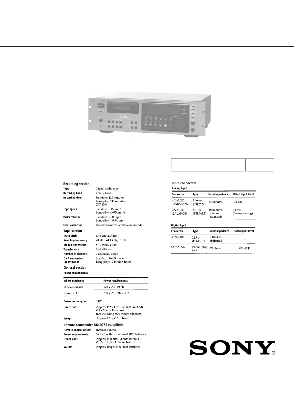
SPECIFICATIONS
US Model
Canadian Model
AEP Model
Model Name Using Similar Mechanism DTC-A8
Tape Transport Mechanism Type
DATM-55
9-960-833-12 Sony Corporation
2002A0500-1 Home Audio Company
C 2002.1 Published by Sony Engineering Corporation
– Continued on next page –
DIGITAL AUDIO TAPE DECK
MODEL IDENTIFICATION
– Model Number label (Printed in Back Panel) –
MODEL NO. PCM-R500
DIGITAL AUDIO TAPE DECK
US, Canadian model : AC 120 V 60 Hz 34 W
AEP Model : AC 230 V
Danger of explosion if battery is incorrectly replaced.
Replace only with the same or equivalent type recommended by the
manufacturer.
Discard used batteries according to the manufacturer’s instructions.
Lithiumbatteri-Eksplosionsfare ved fejlagtig håndtering.
Udskiftning må kun ske med batteri
af samme fabrikat og type.
Levér det brugte batteri tilbage til leverandøren.
Eksplosjonsfare ved feilaktig skifte av batteri.
Benytt samme batteritype eller en tilsvarende type
anbefalt av apparatfabrikanten.
Brukte batterier kasseres i henhold til fabrikantens
Explosionsfara vid felaktigt batteribyte.
Använd samma batterityp eller en ekvivalent typ som
rekommenderas av apparattillverkaren.
Kassera använt batteri enligt fabrikantens instruktion.
⁄
50/60Hz 34 W
CAUTION
ADV ARSEL!
ADVARSEL
instruksjoner.
VARNING
Flexible Circuit Board Repairing
• Keep the temperature of the soldering iron around 270 ˚C during
repairing.
• Do not touch the soldering iron on the same conductor of the
circuit board (within 3 times).
• Be careful not to apply force on the conductor when soldering or
unsoldering .
Notes on chip component replacement
• Never reuse a disconnected chip component.
• Notice that the minus side of a tantalum capacitor may be dam-
aged by heat.
VAROITUS
Paristo voi räjähtää, jos se on virheellisesti asennettu.
Vaihda paristo ainoastaan laitevalmistajan suosittelemaan tyyppiin.
Hävitä käytetty paristo valmistajan ohjeiden mukaisesti.
– 2 –
SAFETY CHECK-OUT
After correcting the original service problem, perform the following safety check before releasing the set to the customer:
Check the antenna terminals, metal trim, “metallized” knobs, screws,
and all other exposed metal parts for AC leakage. Check leakage as
described below.
LEAKAGE TEST
The AC leakage from any exposed metal part to earth ground and
from all exposed metal parts to any exposed metal part having a
return to chassis, must not exceed 0.5 mA (500 microampers). Leakage current can be measured by any one of three methods.
1. A commercial leakage tester, such as the Simpson 229 or RCA
WT-540A. Follow the manufacturers’ instructions to use these
instruments.
2. A battery-operated AC milliammeter. The Data Precision 245
digital multimeter is suitable for this job.
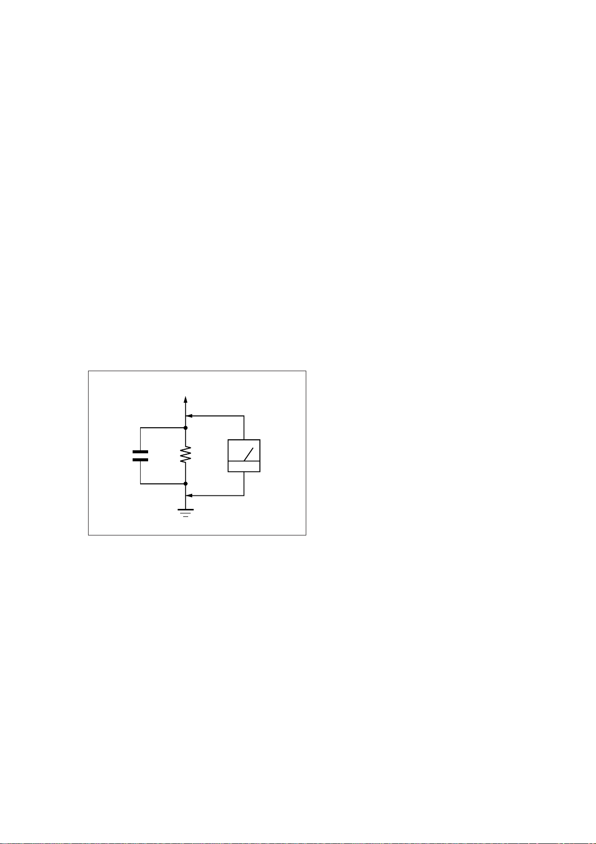
3. Measuring the voltage drop across a resistor by means of a V OM
or battery-operated A C v oltmeter . The “limit” indication is 0.75
V, so analog meters must have an accurate low-voltage scale.
The Simpson 250 and Sanwa SH-63Trd are examples of a passive VOM that is suitable. Nearly all battery operated digital
multimeters that have a 2 V AC range are suitable. (See Fig. A)
TABLE OF CONTENTS
1. GENERAL
..................................................................... 4
2. DISASSEMBLY............................................................ 15
3. ADJUSTMENTS.......................................................... 19
4. DIAGRAMS
4-1. Block Diagrams................................................................. 26
4-2. Printed Wiring Board – RF Section –................................ 33
4-3. Schematic Diagram – RF Section –................................... 35
4-4. Printed Wiring Boards – MD Section –............................. 38
4-5. Schematic Diagram – MD Section –................................. 41
4-6. Printed Wiring Boards – DIGITAL Section – ................... 45
4-7. Schematic Diagram – DIGITAL Section – ........................ 49
4-8. Schematic Diagram – AUDIO Section –........................... 53
4-9. Printed Wiring Boards – AUDIO Section –....................... 57
4-10. Printed Wiring Boards – DISPLAY Section – ................... 61
4-11. Schematic Diagram – DISPLAY Section – ....................... 65
4-12. IC Pin Function Description .............................................. 72
5. EXPLODED VIEWS ................................................... 83
To Exposed Metal
Parts on Set
0.15 µF
1.5 k
Ω
Earth Ground
AC
voltmeter
(0.75 V)
Fig. A. Using an AC voltmeter to check AC leakage.
6. ELECTRICAL PARTS LIST .................................... 91
SAFETY-RELATED COMPONENT WARNING!!
COMPONENTS IDENTIFIED BY MARK ! OR DOTTED
LINE WITH MARK ! ON THE SCHEMATIC DIAGRAMS
AND IN THE PARTS LIST ARE CRITICAL TO SAFE
OPERATION. REPLACE THESE COMPONENTS WITH
SONY PARTS WHOSE PART NUMBERS APPEAR AS
SHOWN IN THIS MANU AL OR IN SUPPLEMENTS PUBLISHED BY SONY.
ATTENTION AU COMPOSANT AYANT RAPPORT
À LA SÉCURITÉ!
LES COMPOSANTS IDENTIFIÉS P AR UNE MARQUE !
SUR LES DIAGRAMMES SCHÉMA TIQUES ET LA LISTE
DES PIÈCES SONT CRITIQUES POUR LA SÉCURITÉ
DE FONCTIONNEMENT. NE REMPLACER CES COMPOSANTS QUE PAR DES PIÈCES SONY DONT LES
NUMÉROS SONT DONNÉS DANS CE MANUEL OU
DANS LES SUPPLÉMENTS PUBLIÉS PAR SONY.
– 3 –
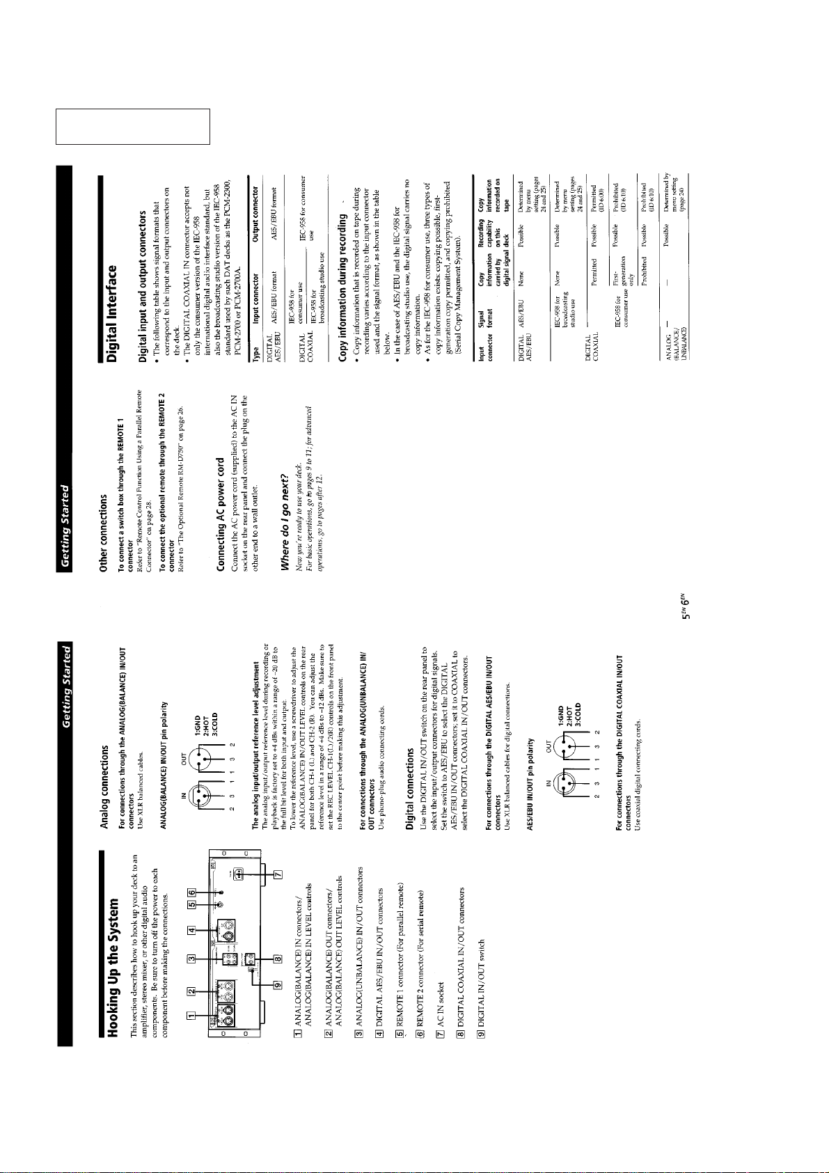
This section is extracted
from instruction manual.
SECTION 1
GENERAL
– 4 –
– 5 –
– 6 –
– 7 –
– 8 –
– 9 –
– 10 –
– 11 –
– 12 –
– 13 –
– 14 –
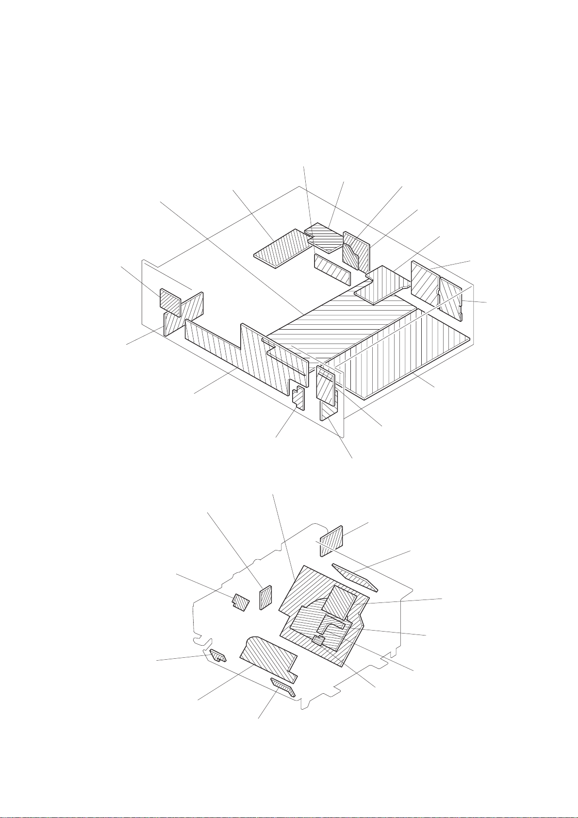
SECTION 2
DISASSEMBLY
Note: Follow the disassembly procedure in the numerical order given.
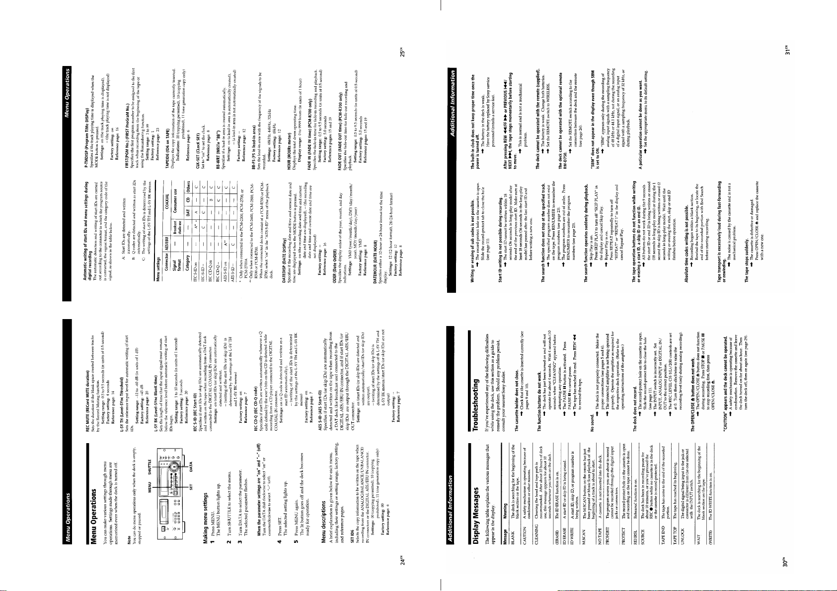
CASE
1
four screws
×
(case)(M3
MECHANISM DECK BLOCK
1
Open the lid.
10)
6
two screws
(PTPWH 3
HOLDER ASS’Y
3
1
two screws
(P2.6
4)
screw (step)
×
3)
8
holder ass’y
7
function plate ass’y
9
cassette compertment
motor ass’y
2
case
1
five screws
×
4
three connectors
(CN506-508)
10)
6
two screws
(B2
×
4)
CASSETTE COMPARTMENT MOTOR ASS’Y
8
0
screw
(B2.6
×
(case) (M3
6
×
6)
two screws
(PTPWH 3
×
6)
nylon washer
4
screw
(BVTT3
×
6)
5
Side plate (R) ass’y
2
two screws
(B2.6
×
4)
2
two claws
5
flat wire
(CN504)
3
lid
2
two claws
7
Remove the mechanism
deck block to direction
of the arrow.
6
1
capstan belt
2
screw
×
(B1.7
screw (B1.7 × 3)
7
slider
3)
ass’y
!¡
chassis (L)
0
screw
×
4)
(B2.6
5
driving gear
4
3
pulley
screw (B1.7 × 3)
– 15 – – 16 –
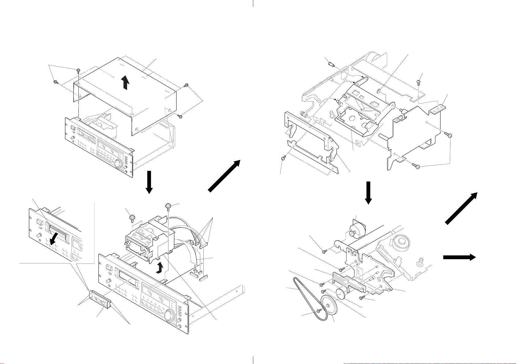
DRUM
1
flexible board (CN7)
DRUM DRIVE BOARD, REEL MOTOR
1
two screws
×
3)
(B2
2
DRUM DRIVE board
3
two screws
(B2
3
two screws
(B2
×
3)
×
3)
2
connector
(CN52)
4
drum
1
two screws
(B2
×
3)
4
bracket
CAPSTAN MOTOR
1
three screws
(P1.7
2
capstan motor
×
4)
5
3
screw
(B2
×
3)
two screws
(B2
×
3)
6
reel motor
– 17 – – 18 –
SECTION 3
ADJUSTMENTS
1. The adjustments are performed in the sequence that they are
described.
2. The required test tapes are:
TY-7111 (8-909-812-00) ................................. Level
TY-7252 (8-909-822-00)................................. Tracking
TY-7551 (8-909-814-00)................................. Function
TY-30B (8-892-358-00)................................... Blank
The required torque meter is:
TW-7131 (8-909-708-71) ................................ FWD
3. Switch and Control Settings
REMOTE switch : OFF
REC MODE switch : 48k (STANDARD)
REC LEVEL control : Minimum
PHONE LEVEL control : Minimum
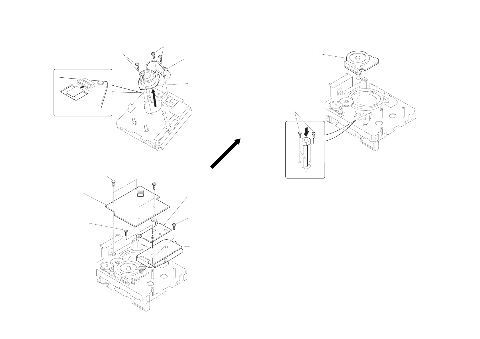
4. Preparation of End Sensor Cassette
(1) Push the slider locks of a cassette tape and slide the slider in
the direction of the arrow.
PRECAUTION
hub hole
slider lock
slider
6. When adjusting tape pass and each guide, as shown below, it is
a good practice to remove the holder assy and use the DAT cassette holder (J-8000-002-A). This facilitates adjustment work.
• When removing and installing the holder assy , turn the pulley
counterclockwise and set loading OUT condition for easy removal and installation.
• When adjusting, turn the pulley clockwise and turn on the
CASSETTE TABLE IN switch (S2) to set loading IN condition. Then, set the test tape.
1
6
Step screw
2
BVTP 3 × 6
3
BVTT 3 × 8
Cassette
spring
5
Nylon washer
7
4
Push down the holder
in the direction
Cassette
holder assy
8. After adjustment is completed, perform the following checks to
verify the tape speed.
(1) Check that with the REC MODE switch set to STAND ARD
48k, tape is normally recorded and played back. (×1)
(2) Check that with the REC MODE switch set to LONG, tape
is normally recorded and played back. (×0.5)
(3) Check that in performing the CUE (” + )) or REVIEW
(” + 0) operation, “kyur kyur” sound is heard. (×3, ×8)
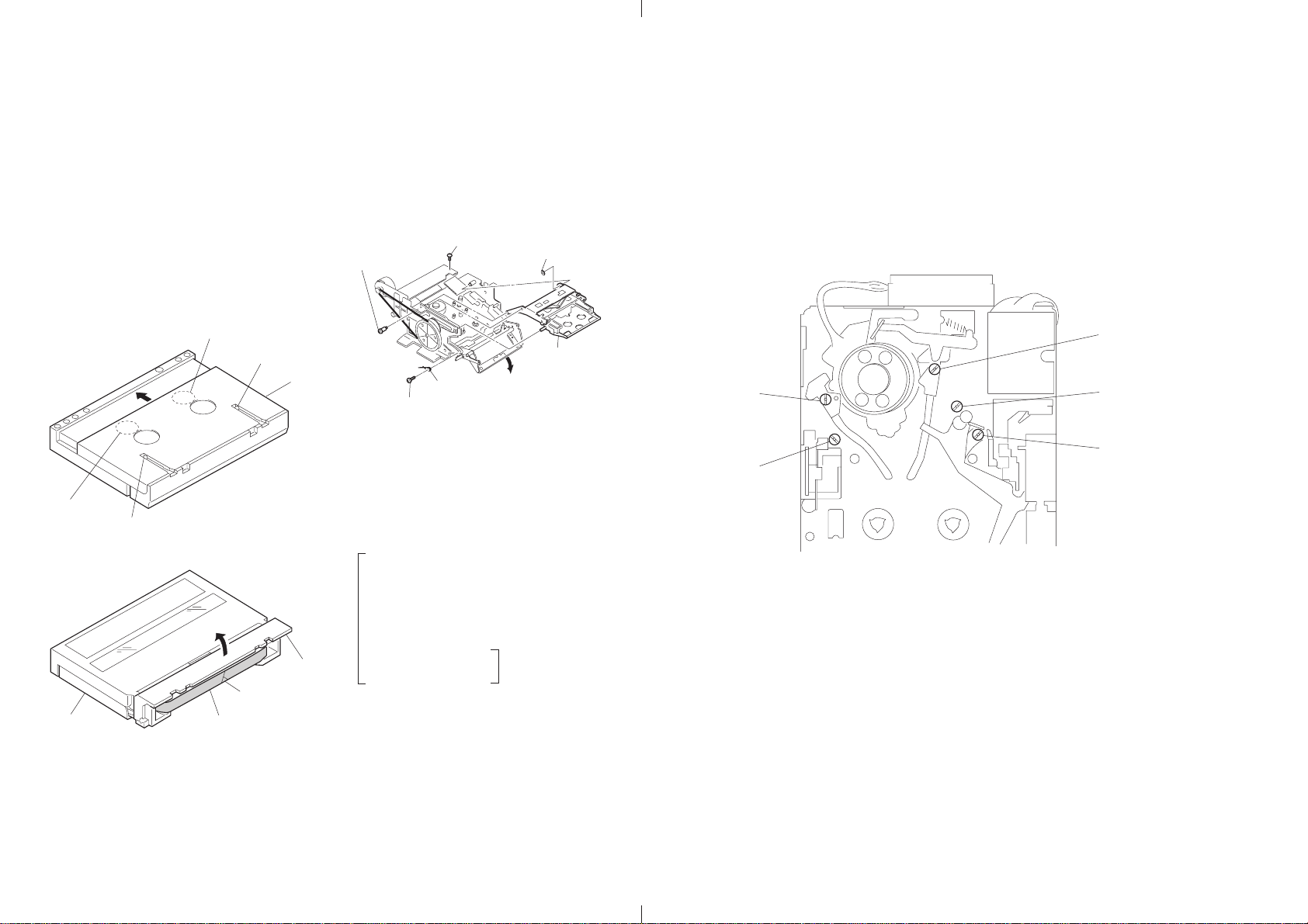
Adjustment Location: mechanism deck block
S1 guide
(4) Check that after performing the FF ()) or REW (0)
operation, the time display is appropriate. (×16)
(5) Check that the AMS (+, =) operation is normal.
T1 guide
T2 guide
hub hole
slider lock
(2) Open the cassette lid and cut tape.
cassette lid
cut tape
slider
(3) Turn the hubs to take-up tape (for both T and S sides).
The end sensor cassette tape for end sensor adjustment is
now prepared.
5. Take care nev er to turn RV1 and R V2 within the RF AMP board
of the cassette compartment section.
tape
7. Test Mode
• T o enter the test mode , short between TP (MAIN-TEST) and
the GND on the DIGITAL board, then turn on the po wer. The
meter scale within the fluorescent indicator tube (FL701) will
flash.
Press the OPEN/CLOSE 6 key and set the test tape. (The
specified tape should be used for each adjustment.)
Test Mode (Short between TP (MAIN-TEST) and GND)
1 Have “DPG” display lit in the fluorescent indicator tube.
(Press the AMS + key.)
• S2, T2 and F Guide Adjustments
• End Sensor Adjustment
• Tape Pass Fine Adjustment (×1.5FWD mode)
• DPG Adjustment
2 Have “TR” display lit in the fluorescent indicator tube.
(Press the ” key.)
• FWD T orque Adjustment
• FWD Back Tension
Adjustment
• T o release the test mode, remove the short between TP (MAIN-
TEST) and GND. After necessary adjustment is completed,
be sure to release the test mode.
(Torque measurement mode)
S2 guide
– 19 – – 20 –
F guide

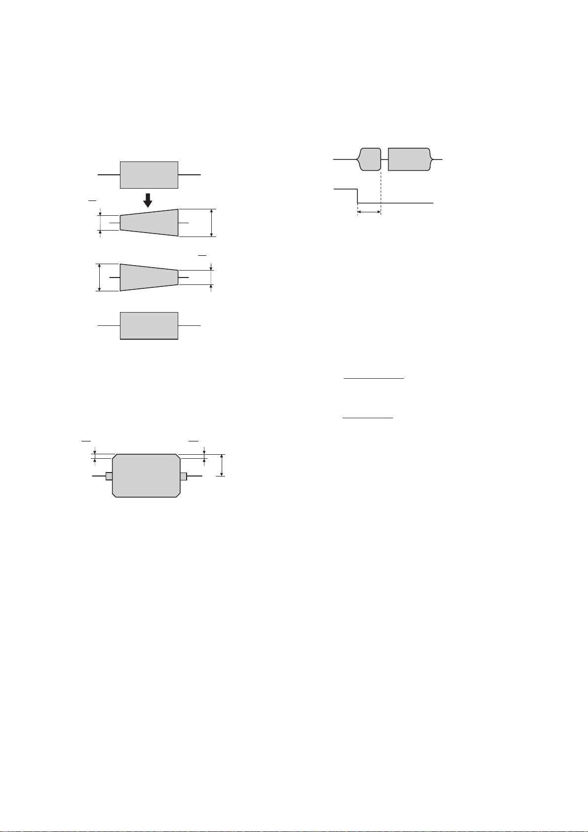
3-1. MECHANICAL ADJUSTMENTS
When replacing any drum related parts, after S2, T2 and F guide
adjustments have been made, tape pass fine adjustment (×1.5FWD
mode) in Electrical adjustment should be performed.
S2, T2 and F Guide Adjustments
Adjustment Method:
1. Enter the Test Mode 1 (see page 19.) and set the test tape TY7252 (8-909-822-00).
2. Set the REC MODE switch to STANDARD 48k and press the
AMS + key.
While in FWD mode, check that there is no curl on the upper
and lower flanges of the S2, T2 and F guides.
If any curl is present, put the S2, T2 and F guide of concern
back in the high position and adjust by adjusting the direction
of tightening.
*
What is curl?
Curl
Distortion that occurs on
tape during FWD operation.
3-2. ELECTRICAL ADJUSTMENTS
End Sensor Adjustment
When removing the holder assy and when replacing the mechanism
deck block, this adjustment should be performed.
Adjustment Method:
1. Connect the CH-1 terminal of an oscilloscope to TP (S-END)
and the CH-2 terminal to TP (T-END) on the DIGITAL board.
2. Enter the Test Mode 1 (see page 19.) and set the end sensor
cassette tape (see page 19.)
3. Set the STOP (p) mode.
4. Adjust RV502 (S-END) and RV501 (T-END) on the DIGITAL
board so that the respective peak to peak values of the waveforms on the oscilloscope are 1.2 Vp-p.
FWD Back Tension Adjustment
Adjustment Method:
1. Enter the T est Mode 2 (Torque Measurement Mode) (see page
19.) and set the torque meter TW-7131 (8-909-708-71).
2. Press the PLAY (”) key.
3. Press the AMS + key or = ke y and adjust so that the back
tension (S side) is within the range of 8.5 ± 0.5 g•cm.
4. When the torque meter is circulating around, check the indicated value.
5. Verify that the maximum value is less than 19.5 g•cm.
REV Torque Check and REV Back Tension Check
Check Method:
1. After FWD torque adjustment and FWD back tension adjustment are completed, press the PLA Y (”) ke y again and set REV
(“) mode.
2. Check that the REV torque value is within the range of 13.5 to
17.5 g•cm and that the REV back tension value is within the
range of 7.5 to 11.5 g•cm.
Tape Pass Fine Adjustment (×1.5FWD Mode)
When replacing any drum related parts, be sure to perform this adjustment.
Adjustment Method:
1. Connect the CH-1 terminal of an oscilloscope to TP (RF) and
the CH-2 terminal to TP (SWP) on the DIGITAL board.
2. Enter the Test Mode 1 (see page 19.) and set the test tape TY7252 (8-909-822-00).
3. Press the AMS (+) key.
Role of each switch in test mode.
OFFSET
–0 +
WIRED OFF
WIRELESS
ATF : ON
STANDARD LONG
ATF : OFF
1.2Vp-p
Adjustment Location: See page 23.
FWD Tor que Adjustment
Adjustment Method:
1. Enter the Test Mode 2 (Torque Measurement Mode) (see page
19.) and set the torque meter TW-7131 (8-909-708-71).
2. Press the PLAY (”) key.
3. Press the ) key or 0 key and adjust so that the FWD torque
value (T side take-up torque) is within the range of 11 to 13
g•cm.
4. When the torque meter is circulating around, check the indicated value.
48k 44.1k
REMOTE REC MODE
4. Put the REC MODE switch to the LONG (ATF: OFF) position
and put the REMOTE switch to either the WIRED or WIRELESS position (OFFSET: – or +), fine adjust both the S1 guide
and T1 guide so that the RF signal waveform of the oscilloscope repeatedly contracts and expands in vertical directions as
it has the same shape.
* Adjust the direction of tightening to complete this adjustment.
If there is curl on any of the upper and lower flanges of the
S2, T2 and F guides, adjust the guide of concern.
– 21 –
5. Put the REC MODE switch to the ST AND ARD 48k (ATF: ON)
s
P
position and put the REMOTE switch to either the WIRED or
WIRELESS position (OFFSET: – or +), then check the RF signal waveform.
4
A or less
5
NG
A
Check that there is a difference of 650 ± 15 µsec between the
oscilloscope’s SWP signal and the RF signal.
RF
SW
650±15 µsec
4
A’ or les
5
NG
A'
OK
6. Put the REC MODE switch to the ST AND ARD 48k (AFT : ON)
position and put the REMOTE switch to the OFF position (OFFSET: 0), then check the RF signal waveform.
(1) Verify that the peak value (B) of the RF signal w a veform is
60mV or more.
(2) Verify that the flat position of the RF signal waveform has
undershoots of 10% or less.
10
B
or less
10
B
or less
B
7. If any of the specified values are not satisfied, repeat items 3 to
6.
Adjustment Location: See page 23.
CHECK AND REPLACEMENT FOR DATE FNCTION
Clock IC Back-up Check
• When r eplacing the lithium battery (BATT501) or replacing any
of the clock IC (IC518) and peripheral parts, the clock will be
reset.
(The DATE display will be [‘-- -- --] [-[PRESENT] button is pushed.)
] even when the
h--m--s
Perform the back-up check by the following procedure.
(1) Connect a DC voltmeter between the DIGITAL board’s TP
(BATT+) as (+) side on the TP (BATT–) as (–) side.
(2) With the POWER switch of the set OFF, check that the volt-
age (1) is
less than +20 mV.
(If the measured value is more than +20 mV, inspect the IC518
and peripheral parts and replace as needed.)
(3) With the POWER switch of the set ON, check that the volt-
age (1) is
less than 0 mV (minus indication), (If plus indication, inspect the D510 and peripheral parts and replace as
needed.)
(4) When these voltages are normal, set the clock to the current
date and time according to the instruction manual.
(year/month/day/day of week/hours/minutes/seconds)*
(5) After the clock is set in item (4), turn off the POWER switch
once and in several seconds, turn on the power again and
make sure that the clock is operating.
Adjustment Location: See page 23.
Adjustment Location: See page 20.
DPG Adjustment
When replacing any drum related parts, be sure to perform this adjustment.
Adjustment Method:
1. Connect the CH-1 terminal of an oscilloscope to TP (RF) and
the CH-2 terminal to TP (SWP) on the DIGITAL board.
2. Enter the Test Mode 1 (see page 19.) and set the test tape TY7252 (8-909-822-00).
3. Put the REC MODE switch to the ST AND ARD 48k (ATF: ON)
position and put the REMOTE switch to the OFF position (OFFSET: 0).
4. Press the AMS (+) key.
5. Press the PLAY (”) key.
6. “DPG OK” is displayed in the fluorescent indicator tube.
– 22 –
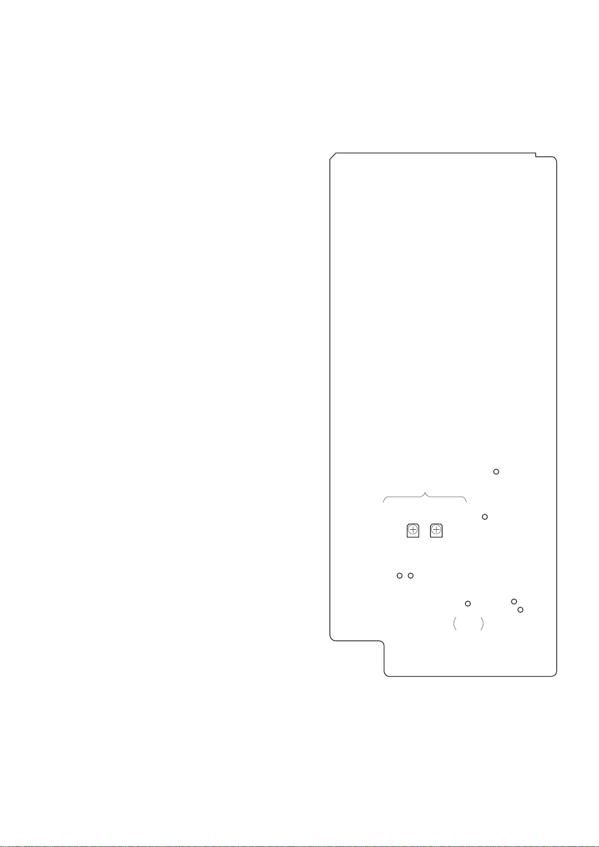
Replacement of Back-up Battery
(S-END)
RV502
(T-END)
RV501
TP
(RF)
TP
(SWP)
TP
(T-END)
TP
(S-END)
TP
(BATT+)
TP
(BATT–)
TP
MAIN–
TEST
END SENSOR ADJ
The back-up battery for clock is designed to serve for more than
seven years under normal service conditions (room temperature and
ordinary humidity).
When replacing the battery, take note of the following:
• P erform the above “Clock IC Back-up Check” and remedy the
cause of battery consumption.
• The open voltage of the battery as removed is 3.0 V or more when
it is new. If this voltage is 2.0 V or less, then battery is fully consumed and needs to be replaced.
• After the battery is replaced, perform the “Clock IC Back-up
Check” again and set the clock.
• The coin type lithium battery (CR2032) is used for replacement.
* For description of the clock setting, see page 5.
Adjustment and Check Locations :
DIGITAL board – component side –
– 23 –

– 24 –
SECTION 4
DIAGRAMS
• Circuit Boards Location
Note: A UDIO board and DIGITAL board are supplyed as MAIN board.
REG BOARD
PRIMARY BOARD
DIGITAL BOARD
REMOTE BOARD
DIGITAL OUT BOARD
DIGITAL IN BOARD
UNBAL BOARD
REM SW BOARD
HP BOARD
ANA OUT BOARD
ANA IN BOARD
AUDIO BOARD
DISPLAY BOARD
INPUT SW BOARD
SHUTTLE BOARD
REC BOARD
DRUM DRIVE BOARD
SW BOARD
MOTOR BOARD
S END BOARD
THICK BOARD
REEL MOTOR U-2A
RF BOARD
LOADING MOTOR BOARD
CAPSTAN MOTOR U-17A
(M902)
LOAD SW BOARD
T END BOARD
(M903)
REC EN BOARD
– 25 –
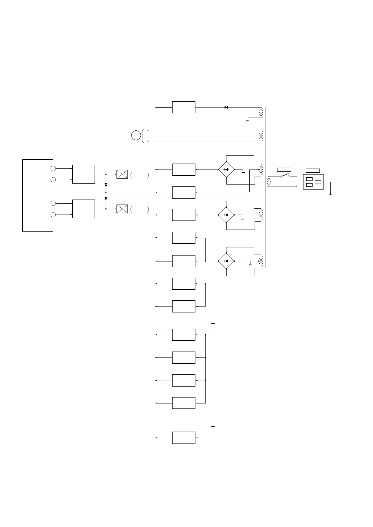
4-1. BLOCK DIAGRAMS
(1) Power Section
FPM KICK
FPM ON
SERVO
PROCESS
IC502 (3/3)
BPM KICK
BPM ON
-33V
FL701
E
F1, F2
1
100
4
3
FWD PM
DRIVE
Q504, 505
Q509, 511
BRAKE PM
DRIVE
Q506-508
Q510
D505
D506
PM902
FWD
PLUNGER
PM901
BRAKE
PLUNGER
+6V
+2V
+5V
+12V
+12V
-12V
-33V REG
Q502, 503
+6V REG
IC902
+2V REG
Q501, 901
+5V REG
IC901
+12V REG
IC319
+12V REG
IC301
-12V REG
IC302
D503
D502
D501
D301-304
T901
S901
POWER
IL901
~
AC IN
L
N
E
-12V
+5V (A)
+5V (B)
+5V (C)
+5V (D)
-5V
-12V REG
IC320
+5V REG
IC316
+5V REG
IC317
+5V REG
IC318
+5V REG
IC305
-5V REG
IC306
+12V
-12V
– 26 –
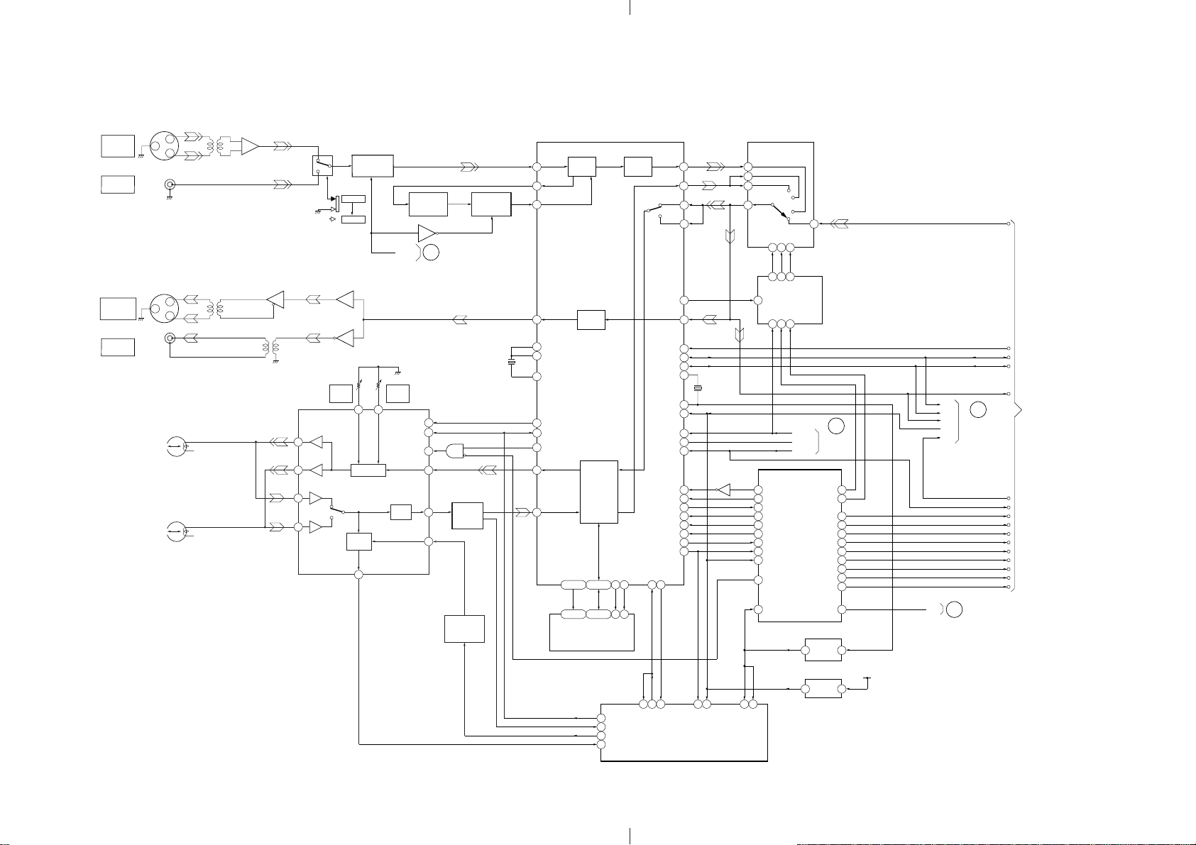
(2) Digital Audio Section
PCM-R500
DIGITAL
IN/OUT
AES/EBU IN
COAXIAL
IN
DIGITAL
IN/OUT
AES/EBU OUT
COAXIAL
OUT
J501-1
J501-2
REC/PB
REC/PB
HEAD
HEAD
J801
1
J802
1
A
B
T801
RS-422 RECEIVER
IC801 (1/2)
T802
12
+
–
11
RS-422 RECEIVER
2
IC801 (1/2)
9
10
T501
IC508
(1/4,4/4)
1
13
5
REC A
33
REC B
27
PB A
34
PB B
26
S501
AES/EBU
-COAXIAL
8
COAXIAL
AES/EBU
IC510 (1/4)
3
6
IC510 (2/4)
RV2
A REC
PCM
NORMALIZER
IC508 (2/4)
IC509 (1/2)
2
4
39 40
REC OCA
PILOT
OCA
PEV
11
VCOEN
RV1
B REC
PCM
PCM
EQ
RF AMP
IC1
PIPC
SWP
REC/PB
GCA
PHASE
CONTROL
IC513 (1/6)
IC513 (6/6)
A
46
47
45
44
1
14
IC513 (5/6, 4/6)
SYSTEM CONTROL
SECTION
Q522
PB RF
BUFFER
Q521
AGC
BUFFER
IC521 (1/2)
RX VCO
D513, Q520
X501
24.576MHz
RX
PDO
PLCO
TX
XT2I
XT3O
XT3I
PIPC
SWP
REPB
REDT
RFDT
A0-A14
1, 2, 4-8
93-100
1-10, 21
23-26
A0-A14
RX
PLL
DAT DSP
SRAM
IC504
IC503
DIGITAL
IN
DAT
DSP
84-89
91, 92
11-13
15-19
D0-D7
D0-D7
79
78
80
66
SWP
PBDT
AGC PWM
ATF
XOE
10 9 19 21
22 27
XOE
52
45
48
54
64
66
67
41
39
42
43
37
ADDI
DIGITAL
OUT
XWE
XWE
79
DADT
77
ADDN
80 9
ADDT
76 10
71 9
LRO1
DADO
78
58
F128
75
BCK
72
LRCK
14
XT1I
XT1O
XRST
MUTA
UNLK
FSEN
EXSN
MUTM
MUTE
EXCK
SDSI
SDSO
SBSY
ATSYATSY
DREF
73 91 72 48 40 43 77
DREF
ATF-S2
ATF-S2
SERVO PROCESS
13
16
47
31
68
57
38
XCS
30
29
23
24
25
26
IC502 (1/3)
X502
18.816MHz
XRST
XSBSY
Q524
SIGNAL SELECT
IC511
11
12
13
STBA
15 2 14
7 2 15
2Q2D
1Q
4Q
D F/F
CLK
IC512
1D
4D
5 4 13
MUTE A
UNLK
FSEN
96
EXSY-MUT
97
XMST-SEL
70
MUT-MONIT
98
MST-MUTE
55
SR-CK
54
SR-DTO
53
SR-DTI
52
XSBSY
XRST
40
REC-DIS
95
43 2
EXTAL
EXTAL
MSTCLK
9.4MHz
SYSTEM
CONTROL
IC501 (1/2)
XANA/DIG
9 11
6 7
XREC/PB
SBM-ON
XADLD
AUSC
AUSO
XADINT
XDAINT
XDALD
XBAL
1/2
DIVIDER
IC519
RESET
IC516
B
SYSTEM
CONTROL
SECTION
FS48
FS44
AIN
F128
BCK
LRCK
DADO
BCK
C
LRCK
DADO
SYSTEM
XRST
CONTROL
SECTION
XLM
16
15
1
11
8
7
28
29
93
94
12
ANALOG
XBAL
AUDIO
D
SECTION
18.8MHz
+5V
FSEN
SBM
ADLD
AUSC
AUSO
FS48
FS44
ADINT
DAINT
DALD
XLM
ANALOG AUDIO SECTION
2
3
2
3
– 27 – – 28 –
 Loading...