

SONY®
Digital Audio Tape Deck
| Operating Instructions | EN |
|---|---|
| Mode d'emploi | F |
| Bedienungsanleitung | D |


PCM-R500 PCM-R700
© 1996 by Sony Corporation
WARNING
To prevent fire or shock hazard, do not expose the unit to rain or moisture.
To avoid electrical shock, do not open the cabinet. Refer servicing to qualified personnel only.
For the customers in the United States
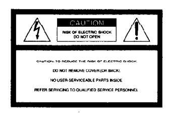
This symbol is intended to alert the user to the presence of uninsulated "dangerous voltage" within the product's
enclosure that may be of sufficient magnitude to constitute a risk of electric shock to persons
This symbol is intended to alert the user to the presence of important operating and maintenance (servicing) instructions in the literature accompanying the appliance.
Owner's Record
The model and serial numbers are located on the rear of the unit. Record the serial number in the space provided below. Refer to them whenever you call upon your Sony dealer regarding this product.
Model No. PCM-R500/PCM-R700
INFORMATION
This equipment has been tested and found to comply with the limits for a Class B digital device, pursuant to Part 15 of the FCC Rules.
These limits are designed to provide reasonable protection against harmful interference in a residential installation. This equipment generates, uses, and can radiate radio frequency energy and, if
radiate radio frequency energy and, if not installed and used in accordance with the instructions, may cause harmful interference to radio communications. However, there is no guarantee that interference will not occur in a particular installation. If this equipment does cause harmful interference to radio or television reception, which can be determined by turning the equipment off and on, the user is encouraged to try to correct the interference by one or more of the
following measures:
- Reorient or relocate the receiving antenna.
- Increase the separation between the equipment and receiver.
- Connect the equipment into an outlet on a circuit different from that to which the receiver is connected.
- Consult the dealer or an experienced radio/TV technician for help.
CAUTION
You are cautioned that any changes or modifications not expressly approved in this manual could void your authority to operate this equipment.
For the customers in Canada
CAUTION
TO PREVENT ELECTRIC SHOCK, DO NOT USE THIS POLARIZED AC PLUG WITH AN EXTENSION CORD, RECEPTACLE OR OTHER OUTLET UNLESS THE BLADES CAN BE FULLY INSERTED TO PREVENT BLADE EXPOSURE.
Voor de klanten in Nederland
Bij dit produkt zijn batterijen geleverd. Wanneer deze leeg zijn, moet u ze niet weggooien maar inleveren als KCA.
VARNING

Explosionsfara vid felaktigt batteribyte. Använd samma batterityp eller en ekvivalent typ som rekommenderas av
apparattillverkaren. Kassera använt batteri enligt fabrikantens instruktion.
ADVARSEL!
Lithiumbatteri - Eksplosionsfare ved fejlagtig håndtering. Udskiftning må kun ske med batteri af samme fabrikat og type. Levér det brugte batteri tilbage til leverandøren.
VAROITUS
Paristo voi räjähtää, jos se on virheellisesti asennettu. Vaihda paristo
ainoastaan laitevalmistajan suosittelemaan tyyppiin. Hävitä
käytetty paristo valmistajan ohjeiden mukaisesti.
ADVARSEL
Eksplosjonsfare ved feilaktig skifte av batteri. Benytt samme batteritype eller en tilsvarende type anbefalt av apparatfabrikanten. Brukte batterier kasseres i henhold til fabrikantens instruksjoner.
Welcome!
Thank you for purchasing the Sony Digital Audio Tape Deck. Before operating the unit, please read this manual thoroughly and retain it for future reference.
The PCM-R500 and PCM-R700 have the following common and distinguishing features.
Common features
- 4DD (Direct Drive) motor mechanism.
- SBM (Super Bit Mapping) function (during analog recording). Support for three sampling
- Support for three sampling frequencies (48 kHz, 44.1 kHz, 32 kHz).
- Installable in a 19-inch rack.
- Analog balanced XLR in/out jacks.
- Professional-use AES/EBU digital interface.
- Connectors for parallel and serial remote control.
- Easy menu operations using the SHUTTLE and DATA dials.
- Mark & Locate function.
- Independent REC LEVEL controls for left and right channels for analog signals
PCM-R700
- Four heads to allow monitoring of the recorded sound during recording.
- Fade-in/out recording and playback function.
- Key Protect function
Additional functions (with the optional remote only)
RMS play, Music Scan, and writing and erasing of an end ID are available. For details, see pages 26 and 27.
About This Manual
The instructions in this manual are for models PCM-R500 and PCM-R700. All illustrations in this manual show th PCM-R500 unless the illustration is
indicated as that of PCM-R700.
Conventions
- Controls in the instructions are those on the deck; these may, however, be substituted by controls on the remote that are similarly named or, when different, appear in the instructions within brackets.
- The following icon is used in this manual:

TABLE OF CONTENTS
Getting Started
Unpacking 4 Rack Mounting 4 Hooking Up the System 5 Digital Interface 6 Setting the Clock 8
Playing a Tape 9 Recording on a Tape 10
Advanced Recording Operations
Things You should know Before Recording 12 Setting the Recording Mode 13 Using the SBM (Super Bit Mapping) Function 13 Locating the End of the Recorded Portion (End Search) 14 Inserting a Sound-Muted Section While Recording (Record Muting) 14 Monitoring the Recorded Sound (Record Monitoring) (PCM-R700 Only) 15
Fade-in/Fade-out Recording (Fader) (PCM-R700 only) 15
Advanced Playback Operations
About the Display 16 Locating a Track (AMS/Direct Access) 17 Locating a Point (Shuttle Play/Mark&Locate) 17 Playing Tracks Repeatedly (Repeat Play) 18 Playing Tracks Skipping Specific Portions During Playback (Skip Play) 18 Fade-in/Fade-out Playback (Fader) (PCM-R700 only) 19
Writing Sub Codes
About Sub Codes Writing Start IDs During Recording Writing Skip IDs During Recording Writing Sub Codes During Playback Adjusting the Position of an Existing Start ID Erasing Sub Codes Renumbering the Program Numbers Automatically (Renumbering Function)
Menu Operations
Menu Operations 24
Operations Using the Optional Remote
The Optional Remote RM-D750 26 Writing and Erasing an End ID 27
Additional Information
Remote Control Function Using a Parallel Remote Connector 28 Disabling Button Operations (Key Protect Function) (PCM-R700 Only) 28 Precautions 29
Cleaning 29 Display Messages 30 Troubleshooting 30 Specifications 32
Index 33
EN
Unpacking
Check that you have received the following supplied items:
- AC power cord (1)
- Remote commander (remote) RM-D757 (1)
- Size-AA (R6) batteries (2)
- Screws (M5×12) (4)
- Decorative washers (4)
- Operating instructions (1)
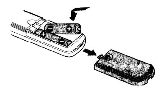
Inserting batteries into the remote
Insert two size-AA(R6) batteries, matching the + and – on the batteries with the markings inside the battery compartment.
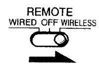
Before using the remote
Set REMOTE on the front panel to WIRELESS.
ϔ When to replace the batteries
With normal use, batteries should last for about 6 months. When the remote no longer operates the deck, replace both batteries.
Notes
- Do not leave the remote near an extremely hot or humid place.
- Do not drop any foreign matter into the remote casing, particularly when replacing the batteries.
- Do not expose the remote sensor to direct sunlight or illumination as doing so may cause malfunction.
- When not using the remote for an extended period of time, remove the batteries to avoid possible damage from battery leakage and corrosion
Rack Mounting
You can install your deck in a 19-inch 3U size rack. Be sure to disconnect the deck from the wall outlet before you install it.
1 Remove the four feet from the deck.
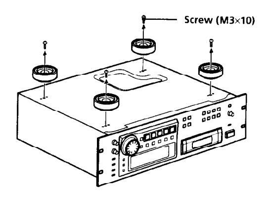
2 Insert the deck into the rack and secure it with the supplied decorative washers and screws (M5×12).
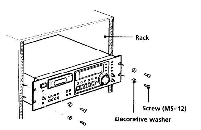
Note
Do not reattach the screws directly after removing the four feet. Put the screws and the feet in a safe place for reattachment in the future. Using longer or shorter screws may damage the internal circuit board.
4 EN
Hooking Up the System
This section describes how to hook up your deck to an amplifier, stereo mixer, or other digital audio components. Be sure to turn off the power to each component before making the connections.
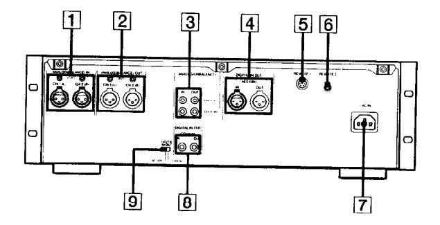
- 1 ANALOG(BALANCE) IN connectors/ ANALOG(BALANCE) IN LEVEL controls
- 2 ANALOG(BALANCE) OUT connectors/ ANALOG(BALANCE) OUT LEVEL controls
- 3 ANALOG(UNBALANCE) IN/OUT connectors
- └______ DIGITAL AES/EBU IN/OUT connectors
[5] REMOTE 1 connector (For parallel remote)
6 REMOTE 2 connector (For serial remote)
7 AC IN socket
8 DIGITAL COAXIAL IN/OUT connectors
9 DIGITAL IN/OUT switch
Analog connections
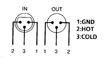
For connections through the ANALOG(BALANCE) IN/OUT connectors
Use XLR balanced cables.
ANALOG(BALANCE) IN/OUT pin polarity
The analog input/output reference level adjustment
The analog input/output reference level during recording or playback is factory set to +4 dBs within a range of -20 dB to the full bit level for both input and output.
To lower the reference level, use a screwdriver to adjust the ANALOG(BALANCE) IN/OUT LEVEL controls on the rear panel for both CH-1 (L) and CH-2 (R). You can adjust the reference level in a range of +4 dBs to -12 dBs Make sure to set the REC LEVEL CH-1(L)/2(R) controls on the front panel to the center point before making this adjustment.
For connections through the ANALOG(UNBALANCE) IN/
Use phono-plug audio connecting cords.
Digital connections
Use the DIGITAL IN/OUT switch on the rear panel to select the input/output connectors for digital signals. Set the switch to AES/EBU to select the DIGITAL AES/EBU IN/OUT connectors; set it to COAXIAL to select the DIGITAL COAXIAL IN/OUT connectors.
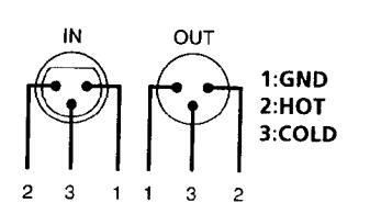
For connections through the DIGITAL AES/EBU IN/OUT connectors
Use XLR balanced cables for digital connections.
AES/EBU IN/OUT pin polarity
For connections through the DIGITAL COAXIAL IN/OUT connectors
Use coaxial digital connecting cords.
Getting Started
Other connections
To connect a switch box through the REMOTE 1 connector
Refer to "Remote Control Function Using a Parallel Remote Connector" on page 28.
To connect the optional remote through the REMOTE 2 connector
Refer to "The Optional Remote RM-D750" on page 26.
Connecting AC power cord
Connect the AC power cord (supplied) to the AC IN socket on the rear panel and connect the plug on the other end to a wall outlet.
Where do I go next?
Now you're ready to use your deck. For basic operations, go to pages 9 to 11; for advanced operations, go to pages after 12.
Digital Interface
Digital input and output connectors
- The following table shows signal formats that correspond to the input and output connectors on the deck.
- The DIGITAL COAXIAL IN connector accepts not only the consumer version of the IEC-958 international digital audio interface standard, but also the broadcasting studio version of the IEC-958 standard used by such DAT decks as the PCM-2300, PCM-2700 or PCM-2700A.
| Tuno | Input connector | Output connector |
|---|---|---|
| туре | ||
|
DIGITAL
AES/EBU |
AES/EBU format | AES/EBU format |
| DIGITAL |
IEC-958 for
consumer use |
IEC-958 for consumer |
| COAXIAL |
IEC-958 for
broadcasting studio use |
use |
Copy information during recording
- Copy information that is recorded on tape during recording varies according to the input connector used and the signal format, as shown in the table below.
- In the case of AES/EBU and the IEC-958 for broadcasting studio use, the digital signal carries no copy information.
- As for the IEC-958 for consumer use, three types of copy information exists: copying possible, firstgeneration copy permitted, and copying prohibited (Serial Copy Management System).
|
Input
connector |
Signal
format |
Copy
information carried by digital signal |
Recording
capability on this deck |
Copy
information recorded on tape |
|---|---|---|---|---|
|
DIGITAL
AES/EBU |
AES/EBU | None | Possible |
Determined
by menu setting (pages 24 and 25) |
|
IEC-958 for
broadcasting studio use |
None | Possible |
Determined
by menu setting (pages 24 and 25) |
|
|
DIGITAL
COAXIAL |
Permitted | Possible |
Permitted
(ID 6:00) |
|
|
IEC-958 for
consumer use |
First-
generation only |
Possible |
Prohibited
(ID 6:10) |
|
| Prohibited | Possible |
Prohibited
(ID 6:10) |
||
|
analog
(Balance, UNBALANCE |
/
|
Possible |
Determined by
menu setting (page 24) |
Mriting start IDs automatically during cording
- When "AUTO" appears in the display during recording, the automatic writing of start IDs takes place according to the input connector used and the signal format, as shown in the table below.
- The condition for the automatic writing of start IDs differs according to the category code in the digital signal, such as an audio input level signal, a DAT start ID code, or a Q-code from a CD track (see pages 24 and 25 ).
| D: automatic | writing | possible |
|---|---|---|
| ×: automatic | writing | prohibite |
| Input signal |
Signal format
(Category code) |
Automatic writing according to | ||||
|---|---|---|---|---|---|---|
|
audio input
level ª) |
DAT start
ID 19 |
Q-code from
a CD track |
||||
|
DIGITAL
AES/EDU |
AES/EBU | 0 | O | х | ||
|
IEC-958 fo
broadcasti studio use |
r
ng |
0 | Odi | × | ||
|
DIGITAL
COAXIAL |
IEC-958 | (DAT) | 0 | 0 | × | |
|
for
consumer |
(CD) | 0 | х | O e) | ||
| use (Other | 0 | × | × | |||
| ANALOG | - | 0 | × | × | ||
- a) If the input level remains under the level set in the "L-SY TH" menu longer than the time set in the "L-SY BK" menu (see page 24), the deck writes a start ID when the input level rises above that level.
- b) DAT skip IDs are automatically written in the same way. c) Only when connected to the PCM-2600, PCM-2800, PCM-
- C) Only when connected to the PCM-2600, PCM-2800, PCM-R500 or PCM-R700. When the connected decks consist of a PCM-R500 or PCM-R700, select "on" in the "AES S-ID" menu of the playback deck.
- d) Only when connected to the PCM-2300, PCM-2700, or PCM-2700A.
- e) Some CD players do not output track information (Q-code) in the digital signal.
Digital signal lock range
- The lock range of a digital signal (signal reception range) is about ±0.1% for a sampling frequency of 48 kHz, 44.1 kHz, or 32 kHz. Variable pitch signals are not receivable.
- When the digital input sampling frequency information does not match the actual sampling trequency, it is possible to record that signal if you change the REC MODE switch on the front panel to
- the actual sampling frequency of the signal.
Getting Started
Setting the Clock
Your deck has a built-in clock to keep track of the current date and time. Once you set the date and time by the menu settings, this information will be recorded on the tape along with the audio signal during recording, allowing you to check the recording date time of the tape during playback at a later time.
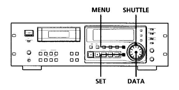
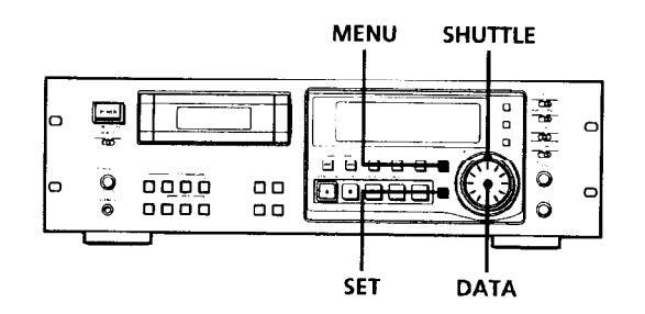
- 1 With the deck stopped, press MENU. The menu appears in the display.
- 2 Turn SHUTTLE to display the "CLK-SET" menu.
- 3 Turn DATA to display "on" and press SET. The year indication flashes.
- 4 Turn DATA to decrease or increase the displayed year, then press SET. The year indication stops flashing and the month indication begins to flash.
5 Repeat step 4 until all items have been set. After setting the seconds, press SET to start the clock.
The day of the week is set automatically and is displayed as follows: Sunday: "SU", Monday: "MO", Tuesday: "TU", Wednesday: "WE", Thursday: "TH", Friday: "FR", Saturday: "SA".
To display the date or time See "About the Display" on page 16.
You can specify the format (12-hour or 24-hour) for the time display, and display order for the date display.
For details, see "ODER" or "DATEHOUR" on page 25.
For more accurate time recordings Adjust the clock once a week.
Notes
- When you first set the clock after unpacking the deck, "'-----" will appear when you press the SET button in step 3. This is normal. Set the clock according to the procedures above.
- Your deck uses a back-up battery to keep the clock running when the power is turned off. The life of the battery under normal use is approximately seven years. When the battery starts to run down, the clock will stop operating normally. When this occurs, have the battery replaced (for a fee) at your dealer or nearest Sony Service Center.
Recording on a Tape
See pages 5 and 6 for bookup information.
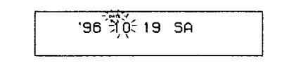
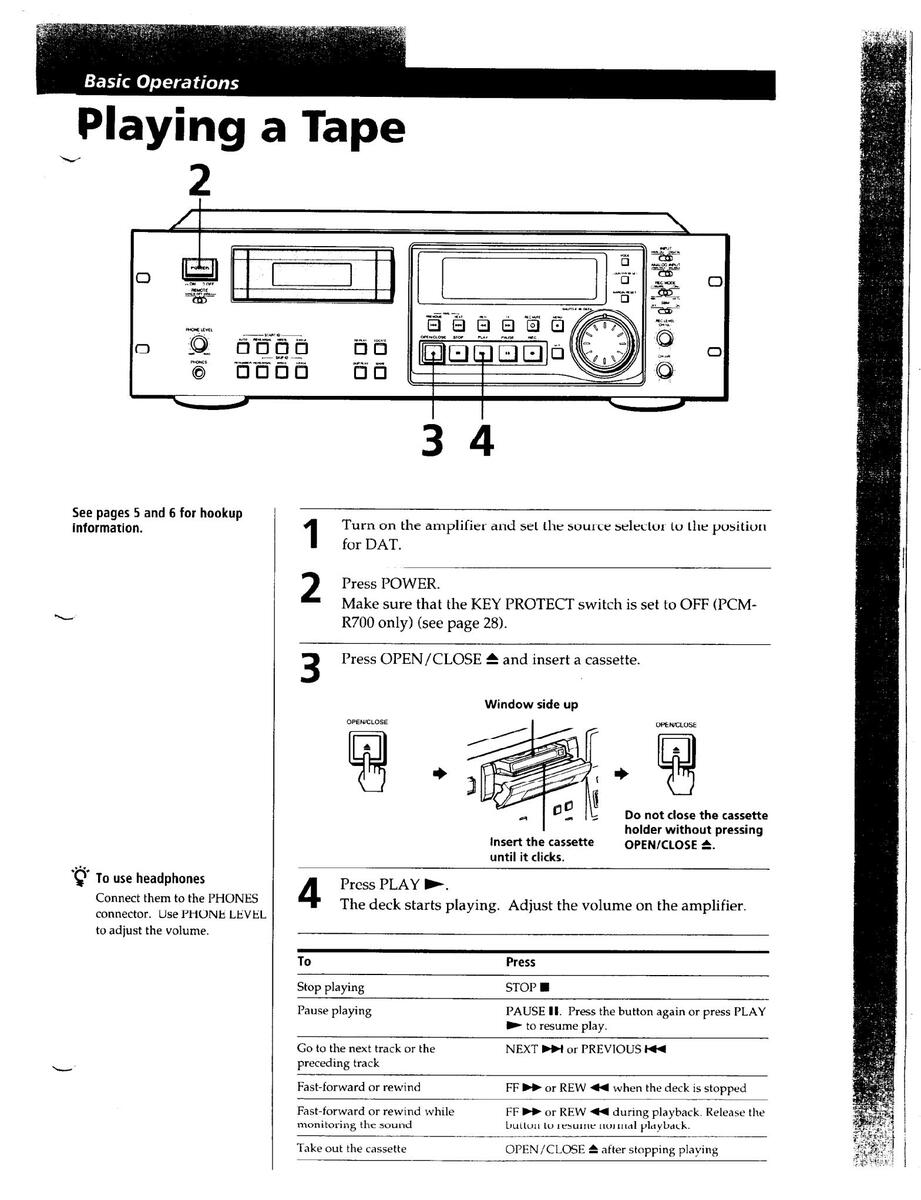
- Turn on the amplifier and play the program source you want to record
-
Press POWER. 2
- Make sure that the KEY PROTECT switch is set to OFF (PCM-R700 only) (see page 28).
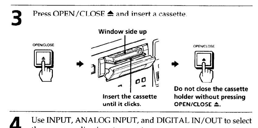
Use INPUT, ANALOG INPUT, and DIGITAL IN/OUT to select the corresponding input connectors.
| Positions of the switches | ||||
|---|---|---|---|---|
| To record through | INPUT | ANALOG INPUT | DIGITAL IN/OUT* | |
|
ANALOG
(BALANCE) IN |
ANALOG | BALANCE | ||
|
ANALOG
(UNBALANCE) IN |
ANALOG | UNBALANCE | ||
|
DIGITAL AES/EBU
IN |
DIGITAL | AES/EBU | ||
|
DIGITAL COAXIAL
IN |
DIGITAL | COAXIAL | ||
* The DIGITAL IN/OUT switch is located on the rear panel (see page 5).
Basic Operations

The program source is not connected to the deck properly or is not turned on. Make sure that the program source is properly connected or turned on.
To adjust the recording level more accurately
While monitoring the sound, turn REC LEVEL CH-1 (L)/2 (R) so that the recording level on the peak level meters is at maximum level without entering the OVER range.
۱.۵ ه .۵ ه Maximum level ک Remains unlit
The segments of the peak level meters corresponding to the maximum signal strength remain lit longer than normal. The MARGIN indication shows the margin between maximum signal strength and 0dB, changing each time a stronger signal.
If the level exceeds 0dB
The segments under "OVER" light up, and "0.0dB" flashes in the display. If these segments light steadily, sound distortion may occur. To avoid this, keep the recording level between -12dB and 0dB
To reset the margin indication
Press MARGIN RESET. The margin indication changes to "- - dB".
Locate the position where you want to start recording.
To record from the beginning of the tape
Press REW 44 to rewind the tape to its beginning.
To record from the end of the recorded portion
1 Press REW ◀◀ to rewind the tape to its beginning.
2 Press FF ►►.
The deck locates the end of the recorded portion on the tape and stops automatically.
6 Press REC ●.
5
The deck changes to recording pause. Recording does not start yet.
When recording an analog input signal, adjust the recording level with REC LEVEL CH-1(L)/2(R).
The recommended recording level is the center point.
Press PAUSE 🚺 or PLAY 🍉.
Recording starts.
Q
Start playing the program source.
When the tape reaches the end, the deck rewinds it automatically to its beginning and stops (Auto Rewind).
| То | Press |
|---|---|
| Stop recording | STOP |
| Pause recording |
PAUSE II. Press the button again
or press PLAY ► to resume recording. |
| Take out the cassette | OPEN/CLOSE ▲ after stopping recording |
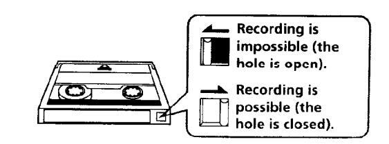
To prevent accidental erasure
Slide the record-protect tab to the left as shown in the illustration below.
Things You Should Know Before Recording
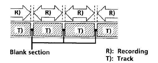
The difference between a blank section and a sound-muted section
The deck distinguishes between two kinds of silent sections, which are respectively called a "blank section" or "sound-muted section".
Blank section
This is a section on which no signal has ever been recorded.
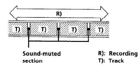
Sound-muted section
This is a section on which a signal has been recorded but at a level that is not audible.
Important
Make sure no blank sections are created while you are recording. The existence of blank sections within recorded material will make search operations using the PREVIOUS I◄◀ /NEXT ►►I buttons impossible or destroy the continuity of the absolute time codes.
Absolute time codes
The absolute time indicates the elapsed time from the beginning of the tape. Once recorded, the absolute time codes cannot be re-written.
For accurate recording of absolute time codes
- If the tape is blank, make sure to start recording from the beginning of the tape.
- Use the Record Muting function (see page 14) to insert spaces between tracks. Do not advance the tape with the PLAY ► or FF ► button.
- To start recording from the middle of a tape, use the End Search function (see page 14) to locate the end of the recorded portion. This will prevent the creation of blank sections.
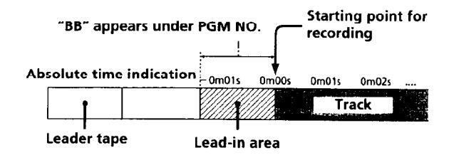
Lead-in area
When the deck is loaded with a new cassette tape and it detects the leader tape, the deck can create a lead-in area depending on the menu setting as shown in the figure below. "BB" appears in the display for about 1 second at this time. The lead-in area can be inadvertently erased on another DAT deck if you press the REC ● button to start recording from the beginning of the tape without closing the cassette holder first. To prevent this, press the OPEN/CLOSE ▲ button to close the cassette holder before you start
recording.
For details on selecting the automatic creation of the lead-in area and the frequency of the signals to be recorded, see "BB-WRT" and "BB-FS" on page 25.
If "EMPHASIS" appears in the display
The deck is recording a digital signal with emphasis (in the higher frequencies). The recording will also contain the same emphasis.
If the deck is left in recording pause for more than 10 minutes
Recording pause will be released automatically and the deck will stop for the sake of tape protection.
"SOURCE" will appear in the display of the PCM-R500.
To resume recording, press the REC ● button. The deck will change to recording pause.
Setting the Recording Mode
You can select between two recording modes, standard or long, in the following cases.
- When recording an analog input signal with the INPUT switch set to ANALOG
- When recording a digital input signal with a sampling frequency of 32 kHz with the INPUT switch set to DIGITAL
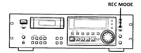
Set REC MODE to select the recording mode.
The following table shows the selectable recording modes and corresponding REC MODE position and sampling frequency for various input signals.
| Input signal | REC MODE position | Recording mode |
|---|---|---|
| Analog |
STANDARD
(48k) |
Standard play
(48kHz) |
|
STANDARD
(44.1k) |
Standard play
(44.1kHz) |
|
| LONG | Long play (32kHz) | |
| Digital (32kHz) |
STANDARD
(48k) |
Standard play
(32kHz) |
|
STANDARD
(44.1k) |
Standard play
(32kHz) |
|
| LONG | Long play (32kHz) | |
| Digital (44.1kHz) |
STANDARD
(48k) |
Standard play
(44.1kHz) |
|
STANDARD
(44.1k) |
Standard play
(44.1kHz) |
|
| LONG |
Standard play
(44.1kHz) |
|
| Digital (48kHz) |
STANDARD
(48k) |
Standard play
(48kHz) |
|
STANDARD
(44.1k) |
Standard play
(48kHz) |
|
| LONG |
Standard play
(48kHz) |
The recording time in long-play mode (the REC MODE switch set to LONG) is twice as long as standard-play mode.
The counter in long-play mode
The displayed tape running time, absolute time and remaining time on the tape are for standard-play mode. Double the time to obtain the corresponding times for long-play mode.
Note
Do not change the INPUT or REC MODE setting while recording. This may cause an error in the "PGM TIME" display.
Using the SBM (Super Bit Mapping) Function
The SBM function uses the principles of human hearing and noise-shaping technology to reduce quantizing noise within the frequency band. You can use the SBM function to record on analog input signal only when the INPUT switch is set to ANALOG and the REC MODE switch to STANDARD (either 48kHz or 44 1kHz)
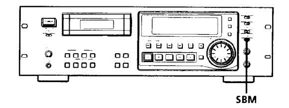
Set SBM to ON.
"SBM" appears in the display during recording using the SBM function.
Note
The SBM function operates only during recording. The improved sound produced by the SBM function, however, can be enjoyed during playback, regardless of the SBM switch position or the DAT deck being used.
Locating the End of the Recorded Portion (End Search)
When recording from the middle of a tape, use End Search to locate the end of the recorded portion. This will prevent the creation of a blank section on the tape.
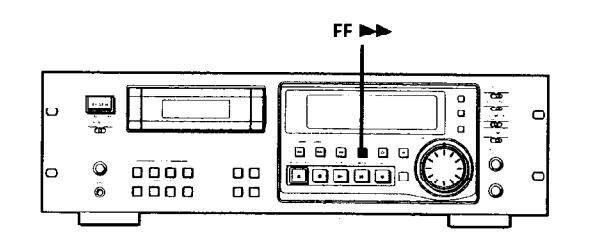
Press FF >> with the deck stopped.
The deck locates the end of the recorded portion (the beginning of the blank portion or the position of the end ID), then stops.
The deck stops at the beginning of any blank section that is 9 seconds or longer, or fast-forwards to the end of the tape if the tape is blank.
♀ When you press the REC ● button while in a blank section
The deck rewinds the tape to the beginning of the blank section and changes to recording pause. "BLANK" and "WAIT" appear in the display while the deck is searching for the beginning of the blank section.
Note
End Search does not operate if you press the FF >> button while in a blank section.
Inserting a Sound-Muted Section While Recording (Record Muting)
Use Record Muting to insert a space of about 0.5 to 9.5 seconds between tracks.
For details on setting the duration of the blank space, see "REC MUTE" on page 24.
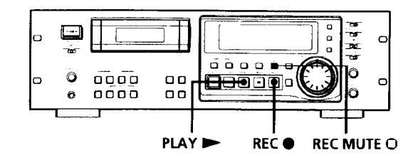
Press REC MUTE O where you want to insert a space while the deck is recording or in recording pause. "REC" in the display starts flashing and tape transport continues, but no signal is recorded. After inserting a space, II in the display stays on and the deck changes to recording pause.
To insert a blank space (of a duration different from that preset by menu setting) Hold down the REC MUTE O button as long as you want.
Hold down the REC MUTE O button as long as you want. When you release the REC MUTE O button, II stays on and the deck changes to recording pause.
When the preset duration has passed, "REC" begins to flash faster and the MARGIN indication shows how long the REC MUTE O button has been pressed.
To insert a blank space of a duration shorter than the preset value
Press REC ● while "REC" is flashing. The deck starts recording again.
Note
If you do not create a sound-muted section at the beginning of a tape, you may not be able to move or crase a start ID (see page 19) that is recorded within 2 seconds from the beginning of the tape.
14EN
Monitoring the Recorded Jound (Record Monitoring) (PCM-R700 Only)

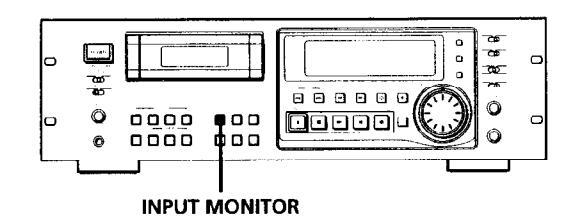
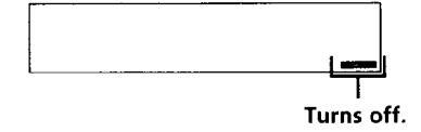
While recording, press INPUT MONITOR to turn off "INPUT" in the display. The recorded sound is output.
To listen to the program source
Press INPUT MONITOR to turn on "INPUT" in the display.
You can listen to the program source even when not recording
Press INPUT MONITOR to turn on "INPUT" in the display.
The program source is output when:
- the deck is stopped.
- the cassette is ejected.
The program source is not output when "INPUT" is turned off.
Note
If you do any of the following operations while listening to the program source, "INPUT" turns off and output of the program source stops, and "INPUT" will not go on even you press the INPUT MONITOR button:
- Start playback by pressing the PLAY >> button.
- Pause playback by pressing the PAUSE II button.
- Press the REW < button.
- Press the FF ▶▶ button.
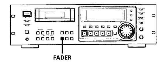
Fade-in/Fade-out Recording (Fader) (PCM-R700 Only)
You can use the fader to fade-in the beginning of a recording or fade-out the end of a recording. It's useful when you want to start or end a recording in the middle of a song.
You can specify the fade-in and fade-out durations of 0.5 to 9.5 seconds through the menu settings.
For details, see "FADE IN" and "FADE OUT" on page 25.
Fading in
Press FADER while the deck is in record pause mode. "FADE IN" appears in the display and the time display counts backward to "0.0s" as the fade-in takes place.
Fading out
Press FADER while the deck is recording.
"FADE OUT" appears in the display and the time display counts backward to "0.0s" as the fade-out takes place. After fading out, the deck automatically enters record pause mode.
Note
Your deck has a digital fader that is capable of fading in or out in 256 steps. Switching noise, however, may occur during recording of low-level or single-frequency signals. If this happens, use a fader on a component, such as a mixer connected to the deck.
About the Display
You can use the display to show the tape running time, absolute time, playing time of the track, remaining time on the tape, date and time of recording, and current date and time.
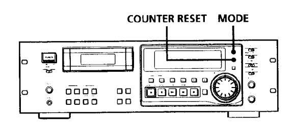
Press MODE repeatedly.
Each time you press the MODE button, the displayed information changes as follows.

- * The playing time of the track will not be displayed when the "P-TMDISP" menu is set to "--" (see page 25).
- ** The date and time of recording and the current date and time will not be displayed when the "DATEDISP" menu is set to "--" (see page 25).
- *** If this information is not recorded on the tape, nothing will appear.
To reset the tape running time
Press COUNTER RESET.
When "DATE" appears in the display
"DATE" remains lit when the date and day of the week or time of recording appears, and flashes when the current date and time appears.
Notes
- When playing certain types of premastered tapes, "BB" may appear momentarily in the display at the beginning of the tape.
- The playing time of the track does not appear in the following cases:
- When you start playing from the middle of the track During rewinding
- In standard-play mode, the remaining time on the tape appears about 16 seconds after you start playing.
- The displayed remaining time may vary somewhat from the actual remaining time, depending on the tape.
If "EMPHASIS" appears in the display
The deck is playing an audio signal recorded with emphasis (in the higher frequencies). The deck, however, plays the signal while automatically deemphasizing it (with attenuation proportional to the degree of emphasis).
"ERR" appears in the display for 5 seconds or more
- The head is dirty. Clean the head with the DAT cleaning cassette (see page 29).
- The cassette is defective or damaged.
16EN
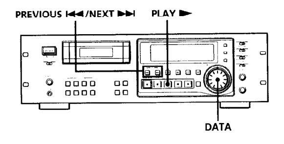
Locating a Track (AMS*/Direct Access)
You can locate the tracks in a number of ways, but only after you have recorded start IDs on the tape (see pages 19 to 23). To use Direct Access, program numbers must be recorded on the tape (see pages 19 and 23).
| To locate | Do the following: | |
|---|---|---|
|
The beginning of the next
or succeeding tracks (AMS) |
Press NEXT
>>
as many times
as you want while playing. For example, to locate the second track ahead, press twice. |
|
| The beginning of the current track (AMS) | Press PREVIOUS I once while playing. | |
| The beginning of preceding tracks (AMS) |
Press PREVIOUS I as many
times as you want while playing. For example, to locate the second track behind, press three times. |
|
|
By specifying the
program number of a track (Direct Access) |
|
|
AMS = Automatic Music Sensor
If you enter the wrong program number during Direct Access
If you haven't pressed the PLAY ► button, turn the DATA dial on the deck (or press the CLEAR button, then enter the correct number on the remote).
If the deck detects a blank section of 9 seconds or more, end ID, or the end of the tape The deck rewinds the tape automatically to its
beginning and stops (Auto Rewind).
You can make the deck start playing automatically from the beginning of the tape after rewinding (Auto Play)
Press the PLAY ► button while holding down the REW ◀ button.
Locating a Point (Shuttle Play/ Mark & Locate)
You can locate a specific point by playing back at a different speed or recording the absolute time code at the point to be located later.

| To locate | Do the following: |
|---|---|
|
A track using variable
speed play (Shuttle Play) |
|
|
A particular point on a
tape (Mark & Locate) |
|
Ö Playback speed during Shuttle Play
During Shuttle Play, you can vary the playback speed
from ±0.5 to ±8 times the normal playback speed (or ±1 to ±8 times the normal playback for material recorded in long-play mode), depending on the angle and direction of the SHUTTLE dial. Turn the dial clockwise for forward playback or counterclockwise for reverse playback.
The playback speed will be ±8 times normal speed playback when you turn the dial to the left or right fully.
Note
Shuttle Play should be used only when necessary since prolonged use may damage the tape and drum.
The point memorized using the Mark & Locate function will be erased when:
— you take out the cassette.
- you turn off the deck.
Advanced Playback Operations
Playing Tracks Repeatedly (Repeat Play)
You can play a specific track or all the tracks on the tape repeatedly.
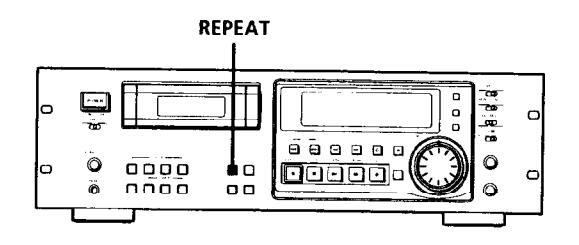
Playing all tracks repeatedly
Press REPEAT repeatedly while playing a track until "REPEAT" appears in the display. The deck will play all tracks 5 times, then stops. If the deck detects either of the following during Repeat Play, it will rewind the tape to its beginning and start playing again.
A blank section of 9 seconds or more The end of the tape or the end ID
To stop playing all tracks repeatedly
Press REPEAT repeatedly until "REPEAT" disappears.
Note
Repeat Play of all tracks is canceled when you take out the cassette.
Playing a track repeatedly
Press REPEAT repeatedly while playing the track you want to repeat until "REPEAT 1" appears in the display. The deck plays the current track 5 times and then
stops.
If the deck detects any of the following during Repeat Play, it will rewind the tape to the start ID of the current track and starts playing again from that position.
--- The next start ID
- A blank section of 9 seconds or more
- The end of the tape or end ID
- A skip ID with Skip Play activated
To stop playing a track repeatedly
Press REPEAT repeatedly until "REPEAT 1" disappears.
lote
Repeat Play of a single track is canceled when you take out the cassette
Playing Tracks Skipping Specific Portions During Playback (Skip Play)
Please note that skip IDs (see page 19) must be written on the tape before you can use Skip Play.
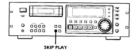
Press SKIP PLAY.
"SKIP PLAY" appears in the display. When the deck detects a skip ID, it fast-forwards the tape to next start ID, then resumes playing.
To cancel Skip Play Press SKIP PLAY. "SKIP PLAY" disappears.
Note
Skip Play is canceled when you take out the cassette.
Advanced Playback Operations
Fade-in/Fade-out Playback (Fader) (PCM-R700 only)
You can use the fader to fade-in the beginning of playback or fade-out the end of Playback. It's useful when you want to record from DAT.
You can specify the fade-in and fade-out durations of 0.5 to 9.5 seconds through the menu settings.
For details, see "FADE IN" and "FADE OUT" on page 25.
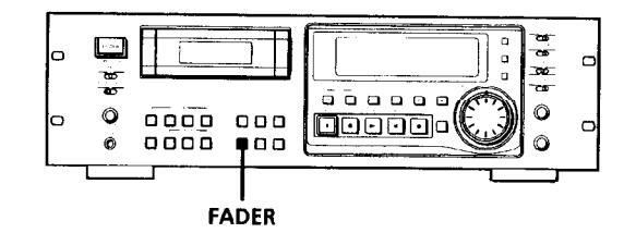
Fading in
Press FADER while the deck is in play pause mode. "FADE IN" appears in the display and the time display counts backward to "0.0s" as the fade-in takes place.
Fading out
Press FADER during playback.
"FADE OUT" appears in the display and the time display counts backward to "0.0s" as the fade-out takes place. After fading out, the deck automatically enters play pause mode.
Note
Your deck has a digital fader that is capable of fading in or out in 256 steps. Switching noise, however, may occur during playback of low-level or single-frequency signals. If this happens, use a fader on a component, such as a mixer, connected to the deck.
About Sub Codes
Writina Sub Codes
In the DAT format, control codes, or sub codes, such as start IDs, skip IDs, and end ID can be recorded on the tape with the audio signal. Since sub codes are written on the tape separately from the audio signal, they have no effect on the audio signal.
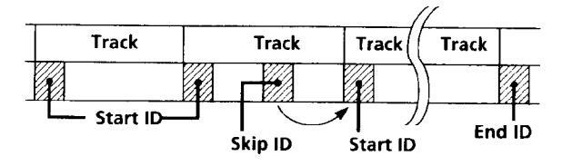
Start IDs
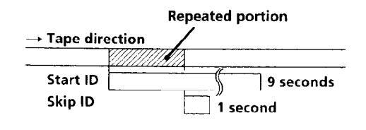
Start IDs indicate the start of a track, and therefore allow you to locate the position of a track precisely. The start IDs are 9 seconds in length (18 seconds in long-play mode) to enable easy detection during fastforwarding or rewinding.
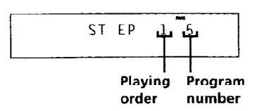
Program numbers
Program numbers serve as track numbers. Occupying the same position as start IDs, a program numbers allow you to locate specific tracks or play tracks in a specific order.
Skip IDs
Skip IDs indicate tracks or recorded portions that are to be skipped while playing. Skip IDs are 1 second in length (2 seconds in long-play mode).
End ID (when the optional remote is used)
An end ID indicates the end of a recording. An end ID is 9 seconds in length (18 seconds in long-play mode). When an end ID is detected during playback, playback stops and the deck rewinds the tape to its beginning. If an end ID is detected during fast-forwarding, the tape stops at that point and deck becomes ready for recording from that point.
You can write and erase an end ID only with the optional remote RM-D750. For details, see "Writing and Erasing an End ID" on page 27.
Notes
- The OPEN/CLOSE ▲, STOP and PAUSE buttons do not work during the writing or erasing of sub codes.
- Writing and erasing of sub codes and renumbering of program numbers are impossible if the record-protect hole on the DAT cassette is open (see page 11).
Writing Start IDs During Recording
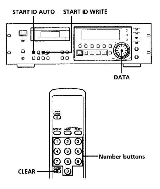
Writing start IDs manually during recording
Press START ID WRITE.
"ID WRITE" appears in the display for a few seconds and the start ID is written on the tape. "START ID" flashes in the display during this time.

Note The in
The interval between start IDs must be more than 18 seconds (36 seconds in long-play mode). If the interval is less than 18 seconds (or 36 seconds), the deck may fail to detect the second start ID while playing a tape.
Writing start IDs automatically during recording
Press START ID AUTO repeatedly until "AUTO" appears in the display.
For details on the condition for the automatic writing of start IDs, see "Writing start IDs automatically during recording" on page 7, and "Menu Operations" on pages 24 and 25.
Writing program numbers during recording
Program numbers occupy the same positions as the start IDs and are determined by depending on the following conditions:
When a program number is displayed
The next program number rises by one above when the next start ID is written.
When no program number is displayed ("--" appears instead)
Program numbers are not written even when start IDs are written. To write program nunbers, rewind the tape to the nearest start ID to display the program number, and then locate the position where you want to start recording.
Specifying the first program number to be assigned
- 1 Pause recording.
- 2 Press the number button(s) on the supplied remote, or turn DATA to input the first program number.
The number appears in the display. To cancel the number, press the CLEAR button on the supplied remote.
3 Start recording.
A start ID and the assigned program number are written simultaneously.
Note
During automatic start ID writing the positioning of some start IDs may be inaccurately or inappropriately positioned away from the beginning of the track. If this happens, you can reposition or erase the start IDs later (see "Accurate positioning of sub codes" on pages 21and 22, and "Erasing Sub Codes" on page 23).
Writing Skip IDs During Recording
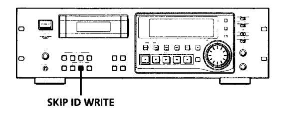
Writing skip IDs manually during recording
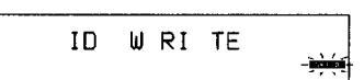
Press SKIP ID WRITE.
"ID WRITE" appears in the display for a few seconds and the skip ID is written on the tape. "SKIP ID" flashes in the display during this time.
Writing Sub Codes During Playback
You can write start IDs or skip IDs during playback.
Press START ID WRITE or SKIP ID WRITE. "ID WRITE" appears in the display for a few seconds and the specified ID is written on the tape at the point you pressed the button.
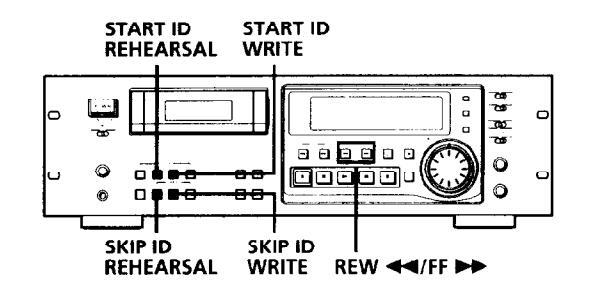
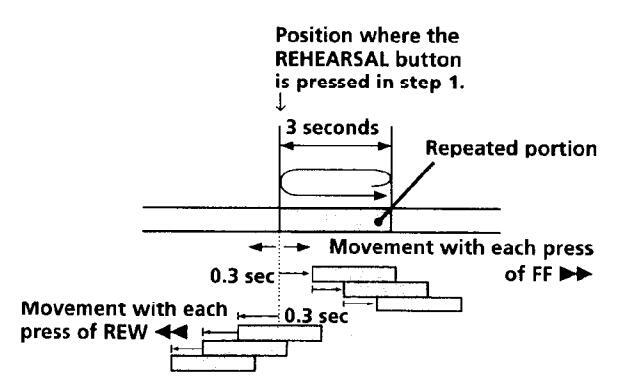
Accurate positioning of sub codes (Rehearsal function)
1 During playback, press REHEARSAL corresponding to the ID you want when you arrive at the proper position.
"REHRSL" appears, the corresponding ID indication flashes in the display and the Rehearsal function repeats a 3-second portion containing the selected position. The repeated portion plays back 8 times, with the remaining number of times appearing to the right of the "REHRSL". After 8 times, the deck stops.
In the case of a start ID, the 3-second repeated portion starts from the point where you pressed the REHEARSAL button.
In the case of a skip ID, the 3-second repeated portion ends at the point where you pressed the REHEARSAL button.
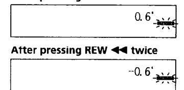
2 Press REW ◄ or FF ► to move the beginning of the repeated portion. Each time you press the REW ◄ or FF ► button, the beginning of the repeated portion shifts backwards or forwards in 0.3-second increments, up to a maximum extent of about 2 seconds (4 seconds in long-play mode) in either direction.
Writing Sub Codes


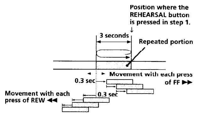
The time in the display shows the shift in position from the time the REHEARSAL button was pressed.
Positioning Start ID
After pressing FF >> twice
3 Press WRITE of the corresponding ID to write the ID.
"ID WRITE" appears for a few seconds and the ID is written on the tape at the selected position.
- Start IDs are 9 seconds long starting from the beginning of the repeated portion.
- Skip IDs are 1 second long starting from the end of the repeated portion.
Newly written IDs positioned by the Rehearsal
Adjusting the Position of an Existing Start ID
You can adjust the position of previously recorded start IDs.
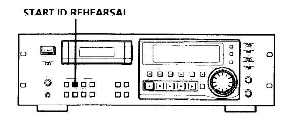
During playback, press START ID REHEARSAL when you arrive at the existing start ID you want to reposition. The deck rewinds to the beginning of start ID and
the Rehearsal function repeats a 3-second portion.
Do the steps 2 and 3 of "Accurate positioning of sub codes" on pages 21 and 22. You can move the start ID to a maximum extent of about 2 seconds (4 seconds in long-play mode) in either direction from its original position.
Notes
- Start IDs written within 10 seconds from the end of the tape may be difficult or impossible to move.
- Existing skip IDs cannot be moved.
22EN
Writing Sub Codes
rasing Sub Codes
You can erase any start ID or skip ID.

Press either START ID ERASE or SKIP ID ERASE when the ID you want to erase appears in the display.
"(ERASE)" appears in the display as the deck rewinds to the beginning of the ID, then "ID ERASE" appears as the deck erases the ID
In the case of a skip ID, if "SKIP ID" has disappeared by the time you press SKIP ID ERASE, the deck will still erase the skip ID.
- It takes 9 seconds to erase a start ID.
- It takes 1 second to erase a skip ID.
- Program numbers are erased together with start IDs.
You can erase an ID even when it is not displayed
Just press the respective ERASE button. The tape is rewound, and the first ID detected is erased.
Note
A skip ID written at the same position of a start ID is erased when the start ID is erased.
Renumbering the Program Numbers Automatically (Renumbering Function)
The Renumbering function searches for each start ID from the beginning of the tape and assigns a new program number to each one starting with 1. Use the Renumbering function in the following cases:
- When you've added a start ID while playing the tape.
- When a program number is missing due to an erased start ID.
- When you began recording from the middle of the tape and wrote a program number that already exists, or when one of the start IDs has no program number.
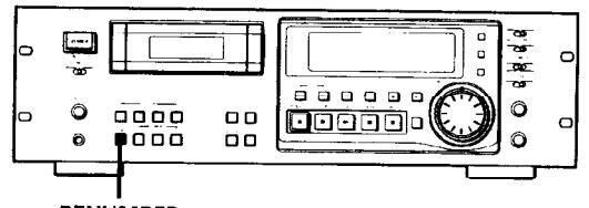
RENUMBER
Press RENUMBER while the deck is stopped or playing.
"KENUMBER" flashes in the display and the tape is automatically rewound to its beginning. The deck then starts searching for each successive start ID writing a new program number for each one starting with 1. "RENUMBER" stops flashing and "ID WRITE" appears in the display for a few seconds as the deck begins rewriting the program numbers. After renumbering is finished, the deck rewinds the tape automatically to its beginning, then stops.
You can specify any number as the starting number for the renumbering of programs.
For details, see "FIRST (PGM No.)" on page 25.
Note
The Renumbering function may not function correctly when:
- A blank section exists on the tape
- The interval between two start IDs is less than 18 seconds (36 seconds in long-play mode).
- A start ID exists within 10 seconds from the end of the tape.
Menu Operations
You can make various settings through mcnu operations. Settings made through menu are memorized even when the deck is turned off.
Note
You can do menu operations only when the deck is empty, stopped or paused.
Making menu settings
- Press MENU. The MENU button lights up.
- 2 Turn SHUTTLE to select the menu.
- 3 Turn DATA to select the parameter. The selected parameter flashes.
When the parameter settings are "on" and "--" (off) Turn the DATA dial clockwise to select "on" or counterclockwise to select "--" (off).
- 4 Press SET. The selected setting lights up.
- 5 Press MENU again. The lit button goes off and the deck becomes ready for operation.
Menu descriptions
A brief explanation is given below for each menu, including their settings or setting range, factory setting, and reference pages.
SET ID6
Selects the copy information to be written on the tape when recording from the ANALOG(BALANCE/UNBALANCE) IN connectors or the DIGITAL AES/EBU IN connector. Settings: 00 (copying permitted), 10 (copying prohibited), 11 (one generation copy only) Factory setting: 00
Reference page: 6
REC MUTE (RECord MUTE duration)
Sets the duration if the blank space created between tracks by the Record Muting function.
Setting range: 0.5 to 9.5 seconds (in units of 0.5 second) Factory setting: 4 seconds Reference page: 14
L-SY TH (Level-SYnc THreshold)
Sets the reference input level for automatic writing of start IDs.
Setting range: -12 to -60 dB (in units of 1 dB) Factory setting: -45 dB Reference page: 20
L-SY BK (Level-SYnc BlanK time)
Sets the length of time that the input signal must remain below the reference level before automatic writing of start IDs begin.
Setting range: 1 to 10 seconds (in units of 1 second) Factory setting: 3 seconds Reference page: 20
Kerenence page. 20
IEC S-ID (IEC Start-ID)
Specifies if start IDs (or skip IDs) are automatically detected and written on the tape when recording from a DAT deck connected to the DIGITAL COAXIAL IN connector.
Settings: on (start IDs (or skip IDs) are automatically detected and written). -- (writing of the start IDs (or skip IDs) is determined by the settings of the L-SY TH
and L-SY BK menus) Factory setting: on
Reference page: 7
IEC CD-Q (IEC CD-Q code)
Specifies if start IDs are written automatically whenever a Q code defined by the user's bits on the CD is detected while recording from a CD player connected to the DIGITAL COAXIAL IN connector.
Settings: on (a Q code is detected and written as a start ID automatically)
start ID automatically),
-- (writing of the start IDs is determined by the settings of the L-SY TH and L-SY BK menus)
Factory setting: on
Reference page: 7
AES S-ID (AES Start-ID)
Specifies if start IDs (or skip IDs) are automatically detected and written on the tape when recording from a DAT deck (for broadcast use) connected to the
a DA1 deck (for broadcast use) connected to the DIGITAL AES/EBU IN connector, and if start IDs (or
skip IDs) are output through the DIGITAL AES/EBU OUT connector.
Settings: on (start IDs (or skip IDs) are detected and written automatically/start IDs (or skip IDs) are output).
-- (writing of start IDs (or skip IDs) is determined by the settings of th L-SY TH and L-SY BK menus/start IDs (or skip IDs) are not
output)
actory setting:
Reference page: 7
Automatic writing of start IDs and menu settings during gital recording
The automatic detection and writing of start IDs are carried out according to the connector to which the program source is connected, the signal format, and the category code of the signal, as shown in the table below.
- A: Start IDs are detected and written automatically.
- B: Q codes are detected and written as start IDs automatically.
- C: The writing of start IDs is determined by the settings of the L-SY TH and L-SY BK menus.
Menu settings
| Connector | AES/EBU | COAXIAL | ||||
|---|---|---|---|---|---|---|
|
Signal
format |
Broadcast
studio use |
Consumer use | ||||
| Category | — | _ | DAT | CD | Others | |
| IEC S-ID on | - | A* | А | С | ||
| IEC-S-ID | С | С | С | |||
| IEC CD-Q on | - | _ | _ | В | С | |
| IEC CD-Q | _ | _ | С | с | ||
| AES S-ID on | A** | — | _ | С | ||
| ~S S-ID | С | - | С | |||
* Only when connected to the PCM-2300, PCM-2700, or PCM-2700A
** Only when connected to the PCM-2600, PCM-2800, PCM-R500 or PCM-R700.
When the connected decks consist of a PCM-R500 or PCM-R700, select "on" in the "AES S-ID" menu of the playback deck.
DATEDISP (DATE DISPlay)
Specifies if the recording date and time and current date and time are displayed when the MODE button is pressed.
Settings: on (the recording date and time and current date and time are displayed), -- (the recording date and time and current date and time are not displayed)
Factory setting: --Reference page: 16
ODER (Date OrDER)
Specifies the display order of the year, month, and day indications.
Settings: YMD (year/month/day), DMY (day/month/ year), MDY (month/day/year) Factory setting: YMD Reference page: 8
DATEHOUR (DATE HOUR)
Specifies either a 12-hour or 24-hour format for the time display.
Settings: 12 (12-hour format), 24 (24-hour format) Factory setting: 12 Reference page: 8
P-TMDISP (Program TiMe DISPlay)
Specifies if the track playing time is displayed when the MODE button is pressed.
Settings: on (the track playing time is displayed), -- (the track playing time is not displayed)
Factory setting: on Reference page: 16
FIRST(PGM No.) (FIRST ProGraM No.)
Specifies the first program number to be assigned to the first track when recording from the beginning of the tape or
using the Renumbering function.
Setting range: 1 to 99 Factory setting: 1 Reference page: 23
TAPEID6 (ID6 on TAPE)
Displays the copy information of the tape currently inserted. Indications: 00 (copying permitted), 10 (copying
prohibited), 11 (one generation copy only) Reference page: 6
CLK-SET (CLocK SET)
Set to "on" to set the clock Reference page: 8
BB-WRT (WRiTe "BB")
Specifies if a lead-in area is created automatically.
Settings: on (a lead-in area is automatically created), -- (a lead-in area is not automatically created)
Factory setting: --Reference page: 12
BB-FS (FS in lead-in area)
Sets the lead-in area with the frequency of the signals to be recorded.
Settings: 48kHz, 44kHz, 32kHz Factory setting: 48kHz Reference page: 12
HOUR (HOURs meter)
Displays the total drum operating time. Display range: 0 to 9999 hours (in units of 1 hour)
FADE IN (FADE IN time) (PCM-R700 only)
Specifies the fade-in time for fade-in recording and playback. Setting range: 0.5 to 9.5 seconds (in units of 0.5 second) Factory setting: 5.0 seconds Reference pages: 15 and 19
FADE OUT (FADE OUT time) (PCM-R700 only)
Specifies the fade-out time for fade-out recording and playback.
Setting range: 0.5 to 9.5 seconds (in units of 0.5 second) Factory setting: 5.0 seconds Reference pages: 15 and 19
The Optional Remote RM-D750
You can do the following operations using serial remote control with an optional remote RM-D750 which may be either connected to the REMOTE 2 connector on the rear panel or not. For more information on other remote operations that are possible, refer to the Operating Instructions of the remote
Note
Set REMOTE on the front panel to WIRED when the rule is connected to the deck. When using it remotely, set REMOTE to WIRELESS.
Playing tracks in the order you want (RMS* Play)
RMS Play allows you to specify the playback order of the tracks on the tape to create your own programs containing up to 60 tracks (using program numbers 1 to 99). To use RMS Play, however, you must first record start IDs and program numbers on the tape.
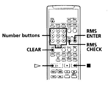
1 Enter the program number (1 to 99) of the track you want to play
If you've entered the wrong number Press CLEAR, then enter the correct number
2 Press RMS ENTER
-
Repeat steps 1 and 2.
- Press 🖂 The deck starts playing the programmed tracks in sequence.
Checking the track order
You can check the order of tracks in your program by pressing the RMS CHECK button. Each time you press the RMS CHECK button, the track numbers appear in the order they were programmed.
Nata
You cannot use the CLEAR button to cancel a programmed track while checking the track order
To add a track to a program
Repeat steps 1 and 2 while the deck is stopped.
You cannot add a track to a program after RMS Play has
To cancel an entire program Press repeatedly until "RMS" disappears.
Locating a track by scanning each track (Music Scan)
You can locate a track by scanning the first 8 seconds of each track.
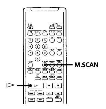
- 1 Press M.SCAN while the deck is stopped.
- 2 Press ⊳. The deck plays the first 8 seconds of each track in succession.
- When you find the track you want, press M.SCAN. The track continues playing.
Ö You can use Music Scan while playing a track If you press the M.SCAN button while playing a track, the deck will rewind the tape to its beginning, then play the first 8 seconds of each track on the tape in
26EN
* RMS = Random Music Sensor
Operations Using the Optional Remote
Writing and Erasing an End ID
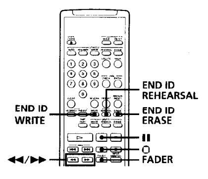
Writing an end ID during recording
When the recording of the program source comes to an end, press II, O, or FADER. Recording is paused.
2 Press END ID WRITE.
"ID WRITE" or "EE" appears in the display while the end ID is being written. When writing has finished, the record pause mode is canceled and the deck rewinds the tape to the beginning of the end ID.
To write an end ID during playback
Press END ID WRITE.
More accurate positioning of the end ID
- During playback, press END ID REHEARSAL. "REHRSL" appears in the display, and the Rehearsal function repeatedly plays back a 3second portion that ends at the point where you pressed the button. The repeated portion plays back 8 times, and the deck stops.
- 2 Press ◄ or ▶ to shift the position of the beginning of the repeated portion. Each time you press ◄ or ▶, the beginning of the repeated portion shifts backwards or forwards by 0.3-second, up to a maximum extent of about 2 seconds (4 seconds in long-play mode) in either direction. The display shows the amount the starting
position has shifted from the time the END ID REHEARSAL button was pressed.
3 After repositioning the beginning of the end ID, press END ID WRITE.
"ID WRITE" appears for a few seconds and the end ID is written on the tape after a duration of about 9 seconds after the end of the the repeated portion.
Erasing the end ID
Press END ID ERASE.
"(ERASE)" appears in the display while the deck fastforwards to the beginning of the end ID, then "ID ERASE" appears while the deck erases the end ID. It takes about 9 seconds (18 seconds in long-play mode) to erase an end ID.
``Ç` You can use the End Search function to locate the end ID
See page 14.
Remote Control Function Using a Parallel Remote Connector
You can operate the deck with a parallel remote control that uses a switch box connected to the REMOTE 1 connector on the rear panel.
Using the REMOTE 1 connector
When operating the deck with a parallel remote control, set the REMOTE switch on the front panel to WIRED.
The pin numbers and pin assignments for the REMOTE 1 connector on the rear panel are as follows:
DIN connector (8 pin)
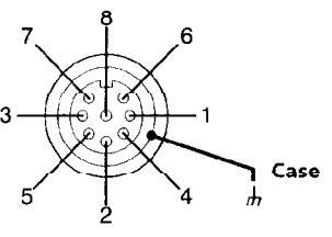
| Pin No |
MODE1
(playback) |
MODE2
(recording) |
|
|---|---|---|---|
| Inputs | 1 | H-level constant | L-level constant |
| 2 | H-STOP/L-PLAY | L-STOP | |
| 3 | L-STOP |
L-START ID
WRITE |
|
| 4 | L-PLAY | L-PLAY | |
| 5 | L-REW | L-PAUSE | |
| 6 | L-FF | L-REC | |
| Status | 7 | H-STOP | H-REC-PAUSE |
| output | 8 | H-PLAY | H-REC |
| Case | GND | GND | |
| Comma | nd inputs | H: OPEN (off impeda | ance: 30 kilohms or |
more) L: CND short (on impedance: 100 ohms or less) Status output H: approx 2V (I=15mA)
L: OPEN (High impedance)
Connection diagram (MODE 1)
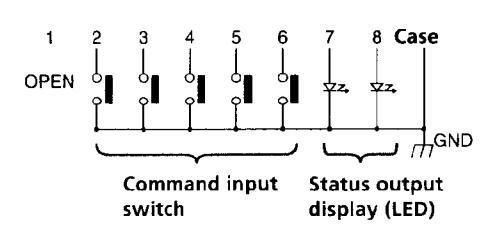
Notes
- When using MODE 2, use pin number 1 for GND.
- By keeping the input to pin number 1 constant at either Hlevel or L-level determines whether pin numbers 2 to 8 are in MODE 1 (playback) or MODE 2 (recording).
- In MODE 1, pin number 2 may be used for fader-start function
- For pin numbers 2 to 6 pin, input to smaller numbers take priority.
- Anti-chattering measures should be taken for the command input switches.
- Status output (pin numbers 7 and 8) is specially provided for driving a single LED. If more current is needed, use an additional drive circuit or electric power supply.
- Do not switch input to pin number 1 (MODE 1 and MODE 2) while the deck is playing or recording. This may result in mis-operation of the deck.
Disabling Button Operations (Key Protect Function) (PCM-R700 Only)
You can disable certain button operations so that the buttons do not work during, for instance, recording.
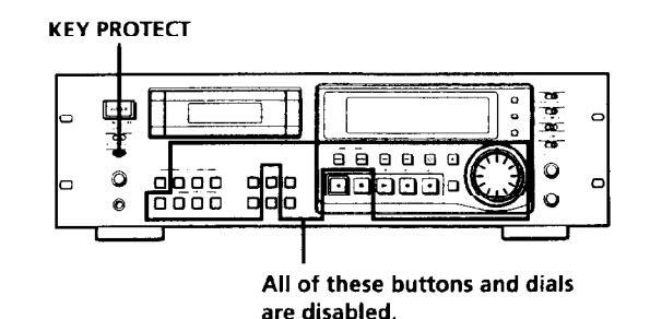
Set KEY PROTECT to ON.
28EN
Precautions
On safety
- Do not disassemble the cabinet as this may result in an electric shock. Refer servicing to qualified personnel only.
- Should any solid object or liquid fall into the cabinet, unplug the AC power cord before operating the unit any further.
On power sources
- Before operating the unit, check that its operating voltage is identical with your local power supply. The operating voltage is indicated on the nameplate at the rear of the unit.
- If you are not going to use the unit for a long time, be sure to disconnect the AC power cord (mains lead) from the wall outlet. To disconnect the cord, grasp the plug itself; never pull the cord.
On operation
If the unit is brought directly from a cold place to a warm place, or is placed in a very damp room, moisture may condense on the lenses inside the unit, "CAUTION" may appear in the display, and the unit may not operate. If this happens, remove the cassette and leave the unit turned on for about an hour until the moisture evaporates.
On placement
- Place the unit in a location with adequate ventilation to prevent heat build-up.
-
Do not place the unit:
- on a soft surface such as a rug that might block the ventilation holes on the bottom.
- near heat sources.
- in direct sunlight.
- in an inclined position. in a place subject to excessive dust or mechanical shock.
On the DAT tapes
- After using a DAT tape, put it into its case and keep it where it will not be subject to sunlight, high temperature moisture or dust.
- The DAT cassette shell is designed to keep out dust. Do not open the case to expose the tape.
- The hole at the back of the cassette is the detector slot. Do not cover this slot.
Regarding tapes of over 120 minutes
Do not use thin-tape cassettes (with a playing time of over 120 minutes) to record important materials since such cassettes are subject to the following problems:
- cassettes are subject to the following problems: Inproper threading of the tape after repeated AMS,
- Inproper threading of the tape after repeated AMS, rewinding, fast-forwarding, or cueing operations. Incorrect writing and erasing of start IDs.
- Sound distortion.
If you have any questions or problems concerning your unit, please consult your nearest Sony dealer.
Cleaning
Cleaning the cabinet, panel and controls
Use a soft cloth slightly moistened with a mild detergent solution. Do not use any type of abrasive pad, scouring powder or solvent such as alcohol or benzine.
Cleaning the head and tape path
- Prolonged operation will cause contamination of the head. To obtain the best possible recording and playback sound, we recommend that you use the Sony DT-10CL cleaning cassette (not supplied) to clean the head after every ten hours or so of operation.
- Clean the head with the cleaning cassette when the deck has not been used for a long period of time. Contamination of the head may cause sound drop-out during playback.
Using the cleaning cassette
- 1 Insert the cleaning cassette as you would a normal DAT cassette.
- 2 Press PLAY ►. After 10 seconds, press STOP ■. Do not press the REC ● or FF ► button for cleaning.
- 3 Remove the cleaning cassette without rewinding it. You should rewind the cleaning cassette only when it has reached the end.
Notes on cleaning
- After 10 hours of operation, "CLEANING" appears in the display for about ten seconds when you turn on the deck. It is recommended that you clean the head and tape path periodically, using this message as a guide.
- Due to the shortness of the cleaning cassette, the counter will not show the actual running time and remaining time of the cassette.
Display Messages
The following table explains the various messages that appear in the display.
| Message | Meaning |
|---|---|
| BLANK | The deck is searching for the beginning of the blank section on the tape. |
| CAUTION | A safety mechanism is operating because of condensation or other reasons. |
| CLEANING |
Cleaning the head and tape path is
recommended. After about 10 hours of deck use, this message appears for about 10 seconds whenever you turn on the deck. |
| (ERASE) | The ID ERASE function is on. |
| ID ERASE | A start ID or skip ID is being crased. |
| ID WRITE | A start ID, skip ID, or program number is being written. |
| M.SCAN |
The M.SCAN button on the remote has just
been pressed or Music Scan playback of the beginning of a track is about to start. |
| NO TAPE | A cassette is not inserted into the deck. |
| PROHIBIT | The program source you are about to record cannot be recorded through the digital input jacks or connectors. |
| PROTECT |
The record-protect hole on the cassette is open
and recording on the tape cannot be done. |
| REHRSL | Rehearsal function is on. |
| SOURCE |
The deck has been in recording pause for
about 10 minutes, or you've pressed the REC ● button while no cassette is in the deck or the cassette is record-protected. |
| TAPE END | The tape has come to the end of the recorded portion. |
| ТАРЕ ТОР | The tape has reached its beginning. |
| UNLOCK |
The digital signal being input to the jack or
connector is different from the one selected with the INPUT switch. |
| WAIT | The deck is searching for the beginning of the blank section on the tape. |
| (WRITE) | The ID WRITE function is on. |
Troubleshooting
If you've experienced any of the following difficulties while using the deck, use this section as a guide to remedy the problem. Should any problem persist, consult your nearest Sony dealer.
The cassette holder does not close.
Check that the cassette is inserted correctly (see pages 9 and 10).
The function buttons do not work.
- → The deck has just been turned on and will not operate for about 4 seconds. Wait 4 seconds (10 seconds when "CLEANING" appears) before attempting any operation.
- ➡ The PAUSE II button is activated. Press PAUSE II to cancel pause.
- The tape has reached its end. Press REW to rewind the tape.
o sound
- The deck is not properly connected. Make the proper connections (see pages 5 and 6).
- The connected amplifier is not being operated properly. Operate the amplifier as required for the respective deck operation. (Refer to the operating instructions of the amplifier.)
The deck does not record.
- The record-protect hole on the cassette is open. Slide the record-protect tab to close the hole (see page 11).
- ➡ The INPUT switch is incorrectly set. Set INPUT, ANALOG INPUT or DIGITAL IN/ OUT to the correct position.
- → The REC LEVEL CH-1(L)/2(R) controls are set at 0. Turn them clockwise to raise the recording level (only during analog recording).
The OPEN/CLOSE 📤 button does not work.
→ The OPEN/CLOSE button does not function during recording. Press STOP ■ or PAUSE ■ to stop recording first, then press OPEN/CLOSE button
"CAUTION" appears and the deck cannot be operated.
→ A safety mechanism is operating because of condensation. Remove the cassette and leave the deck turned on for about an hour. Then turn the deck off, then on again (see page 29).
Additional Information
Writing or erasing of sub codes is not possible.
The record-protect hole on the cassette is open. Slide the record-protect tab to close the hole (see page 11).
Start ID writing is not possible during recording.
seconds (36 seconds in long-play mode) after the end of the previous start ID. Make sure at least 18 seconds (36 seconds in the long-play mode) has passed after the last start ID and before writing a new one.
The search function does not stop at the specified track.
- The specified program number does not exist on the tape. Press RENUMBER to renumber the program numbers (see page 23).
- The program numbers are out of order. Press RENUMBER to renumber the program numbers (see page 23)
The search function operates suddenly during playback.
- → Skip Play is on. Press SKIP PLAY to turn off "SKIP PLAY" in the display and cancel Skip Play.
- Repeat Play is on. Press REPEAT repeatedly to turn off "REPEAT" or "REPEAT 1" in the display and cancel Repeat Play.
The tape operation buttons do not function while writing or erasing a start ID, a skip ID or an end ID.
→ All buttons do not work during the 9 seconds the start ID or end ID is being written or erased (18 seconds in long-play mode) or during the 1 second the skip ID is being written or erased (2 seconds in long-play mode). Wait until the writing or erasing the start, skip or end ID finishes before operation.
Absolute time codes writing is not possible.
Recording began within a blank section. Rewind the tape to its beginning, or locate the end of the recorded portion with End Search before starting recording.
Tape transport is excessively loud during fast-forwarding or rewinding.
The noise is caused by the cassette and is not a mechanical problem.
The tape stops suddenly.
→ The cassette is defective or damaged. Press OPEN/CLOSE ▲ and replace the cassette with a new one.
The built-in clock does not keep proper time once the power is turned off.
The battery in the deck is weak. Have the battery replaced by Sony service personnel (entails a service fee).
After pressing REW ◀◀/FF ►► or PREVIOUS া◀◀ / NEXT ►►I, the tape stops momentarily before starting to move
This is normal and is not a mechanical problem.
The deck cannot be operated with the remote (supplied).
→ The battery is weak. Change both batteries. → Set the REMOTE switch to WIRELESS.
The deck cannot be operated with the optional remote RM-D750.
Set the REMOTE switch according to the connection between the deck and the remote (see page 26).
"SBM" does not appear in the display even though SBM is set to ON.
"SBM" appears only during the recording of analog input signals with a sampling frequency of 48 kHz or 44.1 kHz, not during the recording of a digital input signal, or an analog input signal with a sampling frequency of 32 kHz, or during playback.
A paticular operation cannot be done as you want.
➡ Set the appropriate menu to its default setting.
Additional Information
Specifications Recording section Tape Digital audio tape Recording head Rotary head Standard: 120 minutes Long-play: 240 minutes Tape speed Standard: 8.15 mm/s Long-play: 4.075 mm/s Standard: 2,000 rpm Drum rotation Long-play: 1,000 rpm Error correction Double-encoded Reed Solomon code Tape section Track pitch 13.6 µm (20.4 µm) Sampling frequency 48 kHz, 44.1 kHz, 32 kHz Modulation system 8-10 modulation Transfer rate 2.46 Mbit/sec Number of channels 2 channels, stereo
Standard: 16-bit linear Long-play. 12-bit non-linear
Power requirements
230 V AC, 50/60 Hz
Approx 482 × 145 × 355 mm (w/h/d)
(19×53/4×14 inches) (not including rack mount adaptor)
PCM-R500: Approx 7.2kg (15 lb 14 oz)
3V DC, with two size-AA (R6) batteries Approx 45 × 210 × 26 mm (w/h/d)
Rated input levela)
(factory setting)
-17 dBs
+4 dBs
(113/16×83/8×11/16 inches)
Input impedance
47 kilohms
10 kilohms
(halanced)
Approx 100g (3.5 oz) incl. batteries
PCM-R700: Approx 7.3kg (16 lb 2 oz)
120 V AC, 60 Hz
PCM-R500: 34W
Infrared control
Remote commander RM-D757 (supplied)
D / A conversion
General section
Power requirements
Where purchased
U.S.A./Canada
Power consumption
Remote control system
Power requirements
Input connectors Analog Input Connector
ANALOG Phono-(UNBALANCE) plug jack
Type
XIR-3
Dimensions
ANALOG
Weight
Europe/U.K
Dimensions
Weight
pcm-2500
| Dig | gital | Inp | u |
|---|---|---|---|
| Connector | Туре | Input impedance | Rated input level | |
|---|---|---|---|---|
| AES/EBU |
XLR-3
(FEMALE) |
110 ohms
(balanced) |
_ | |
| COAXIAL |
Phono plug
jack |
75 ohms | 0.5 Vp-p | |
Output connectors
Analog Output
| Connector | Туре |
Output
impedance |
Rated
output level*) |
Load
impedance |
|---|---|---|---|---|
|
ANALOG
(UNBALANCE) |
Phono-plug
jack |
1 kilohm | –12 dBs | 47 kilohms |
|
ANALOG
(BALANCE) |
XLR-3
(MALE) |
100 ohms
(balanced) |
+4 dBs
(factory setting) |
10 kilohms
or more |
| PHONES |
Stereo phone-
plug jack |
100 ohms | 0.36 mW | 32 ohms |
Digital Output
| Connector | Туре |
Output
impedance |
Rated
output level |
Load
impedance |
|---|---|---|---|---|
| AES/EBU |
XLR-3
(MALE) |
35 ohms
(balanced) |
110 ohms | |
| COAXIAL |
Phono-plug
jack |
75 ohms | 0.5 Vp-p | 75 ohms |
Variable range of analog (BALANCE) input/output reference level*
+4 dBe to -12 dBe
| laximum | analog | (BALANCE) | output | level |
|---|---|---|---|---|
| 124 005 | ||
|---|---|---|
| lemote switch connectors |
DIN connector (8-pin, parallel)
Monaural minijack (serial) |
|
| udio characteristics | , | |
| requency response b) |
Standard: 20-20,000 Hz (±0.5 dB)
Long-play: 20-14,500 Hz (±0.5 dB) |
|
| ignal-to-noise ratio b) |
90 dB or more (20 kHz LPF, A-
Weight filter ON) |
|
| otal harmonic distortion b) |
Standard: 0.05% or less
Long-play: 0.3% or less (1 kHz, Reference level * 20 kHz LPF ON) |
|
| Vow and flutter |
Below measurable limit (±0.001%
W.PEAK) |
|
| ) The reference level corre | enonde to _20 dB on the neak | |
level meters.
b) During analog input with the SBM function off
Supplied accessories See page 4.
Design and specifications are subject to change without notice.
32∈N
Index
Α
About the display 16 Absolute time 16 Current date and time 16 Date and time of recording 16 Playing time of the track 16 Remaining time on the tape 16 Tape running time 16 Absolute time codes 12, 17 Adjusting the recording level 11 the clock 8 AMS (Automatic music Sensor) 17 Analog connections 5
В
Batteries 4 Blank section 12, 14
С
Cleaning 29 Copy information during recording 6
D
Digital connections 5 Digital Interface 6, 7 Digital signal lock range 7 Direct Access 17 Disabling Button Operations 28 Display messages 30
Е
Emphasis 12, 16 End ID 19, 27 More accute positioning of the end ID 27 Writing an end ID during recording 27 Writing and erasing an end ID 27 End Search 14 Err 16
F, G
Fade-in/Fade-out Playback 19 Recording 15 Fader 15, 19
Н
Hooking up the system 5, 6 Analog connections 5 Digital connections 5 Other connections 6
I, J
Inserting batteries into the remote 4
Κ
Key Protect Function 28
Lead-in area 12
M, N
Making menu settings 24 Mark & Locate 17 Menu descriptions 24, 25 Music Scan 26
Ο
Optional remote 26, 27
Ρ
Playing a tape 9 Program numbers 19, 20, 23 Writing program numbers during recording 20 Specifying the first program number to be assigned 20
)
Q-code 7, 24, 25
F
Rack mounting 4 Recording on a tape 10, 11 Record Monitoring 15 Record Muting 14 Record-protect tab 11 Rehearsal Function 21, 22 Remote control function 28 Renumbering Function 23 Repeat Play 18 Playing a track repeatedly 18 Playing all tracks repeatedly 18 Playing all tracks repeatedly 18 RMS (Random Music Sensor) Play 26
S, T, U, V, W, X, Y, Z
SBM function 13 Serial Copy Management System 6 Setting the recording mode 13 the clock 8 Shuttle Play 17 Skip Play 18 Skip ID 19, 21-24 Writing skip IDs during recording 21 Sound-muted section 12, 14 Start ID 19-25 Adjusting the position of an existing start ID 22 Writing start IDs during recording 20 Sub Codes 19-23 Accurate positioning of sub codes 21, 22 Erasing sub codes 23 Writing sub codes during playback 21, 22
Names of controls
Buttons
CLEAR 20, 26 COUNTER RESET 16 END ID ERASE 27 END ID REHEARSAL 27 END ID WRITE 27 FADER 15, 19, 27 INPUT MONITOR 15 LOCATE 17 M SCAN 26-30 MARGIN RESET 11 MARK 17 MENU 8 24 MODE 16, 25 PAUSE II 9, 11, 14, 15, 19, 27, PLAY > 9, 11, 12, 14, 15, 17, OPEN/CLOSE ▲ 9 -12, 19, 30, PREVIOUS I /NEXT I 9, 12, 17, 31 REC • 11, 12, 14, 29, 30 REC MUTE • 14, 27 RENUMBER 23.31 REPEAT 18, 31 REW ◀◀/FF ►► 9, 11, 12, 14, 15, 21, 22, 27, 29 - 31 RMS CHECK 26 RMS ENTER 26 SET 8 24 SKIP ID ERASE 23 SKIP ID REHEARSAL 21, 22 SKIP ID WRITE 21.22 SKIP PLAY 18.31 START ID AUTO 20 START ID ERASE 23 START ID REHEARSAL 21, 22 START ID WRITE 20, 22 STOP 🔳 9, 11, 19, 26, 29, 30
33₽№
Index
Switches
ANALOG INPUT 10, 30 DIGITAL IN/OUT 5, 10, 30 INPUT 10, 13, 30 KEY PROTECT 9, 10, 28 POWER 9, 10 REC MODE 7, 13 REMOTE 4, 26, 31 SBM 13, 31, 33
Connectors
ANALOG (BALANCE) IN/ OUT 5, 6, 10, 24, 32 ANALOG (UNBALANCE) IN/OUT 5, 6, 10, 24, 32 DIGITAL AES/EBU IN/OUT 5, 6, 10, 24, 25, 32 DIGITAL COAXIAL IN/OUT 5, 6, 10, 24, 25, 32 REMOTE 1/2 5, 6, 26, 28
Contorols
ANALOG (BALANCE) IN/ OUT LEVEL 5 DATA 8, 17, 20, 24 PHONE LEVEL 9 REC LEVEL CH-1/2 5, 11, 30 SHUTTLE 8, 17, 24
Jacks
PHONES 9, 32


 Loading...