

Page 1

Digital Audio
Tape Deck
3-859-278-12(1)
Operating Instructions
Mode d'emploi
Bedienungsanleitung
Digital AudioTape
____________
SBM
Super Bit Mapping
PCM-R500
PCM-R700
•P 1996 by Sony Corporation
Page 2
WARNING
To prevent fire or shock
hazard, do not expose the unit
to rain or moisture.
To avoid electrical shock, do
not open the cabinet. Refer
servicing to qualified
personnel only.
For the customers in the United States
A
This symbol is intended to alert the user
to the presence of uninsulated
"dangerous voltage" within the
product's
enclosure that may be of sufficient
magnitude to constitute a risk of electric
shock to persons.
This symbol is intended to alert the user
to the presence of important operating
and maintenance (servicing) instructions
in the literature accompanying the
appliance.
Owner's Record
The model and serial numbers are
located on the rear of the unit.
Record the serial number in the space
provided below. Refer to them
whenever you call upon your Sony
dealer regarding this product.
INFORMATION
This equipment has been tested and
found to comply with the limits for a
Class B digital device, pursuant to Part
15 of the FCC Rules.
These limits are designed to provide
reasonable protection against harmful
interference in a residential installation.
This equipment generates, uses, and can
radiate radio frequency energy and, if
not installed and used in accordance
with the instructions, may cause
harmful interference to radio
communications. However, there is no
guarantee that interference will not
occur in a particular installation. If this
equipment does cause harmful
interference to radio or television
reception, which can be determined by
turning the equipment off and on, the
user is encouraged to try to correct the
interference by one or more of the
following measures:
— Reorient or relocate the receiving
antenna.
— Increase the separation between the
equipment and receiver.
— Connect the equipment into an
outlet on a circuit different from that
to which the receiver is connected.
— Consult the dealer or an experienced
radio/TV technician for help.
CAUTION
You are cautioned that any changes or
modifications not expressly approved in
this manual could void your authority
to operate this equipment.
For the customers in Canada CAUTION
TO PREVENT ELECTRIC SHOCK, DO
NOT USE THIS POLARIZED AC PLUG
WITH AN EXTENSION CORD,
RECEPTACLE OR OTHER OUTLET
UNLESS THE BLADES CAN BE FULLY
INSERTED TO PREVENT BLADE
EXPOSURE.
Voor de klanten in Nederland
Bij dit Produkt zijn batterijen geleverd.
Wanneer deze leeg zijn, moet u ze niet
weggooien maar inleveren als KCA.
VARNING
Explosionsfara vid felaktigt
batteribyte. Använd samma
batterityp eller en
ekvivalent typ som
f
apparattillverkaren. Kassera använt
batteri enligt fabrikantens instruktion.
ADVARSEL!
Lithiumbatteri - Eksplosionsfare ved
fejlagtig hàndtering. Udskiftning ma
kun ske med batteri af samme fabrikat
og type. Levér det brugte batteri tilbage
til leverandoren.
VAROITUS
Paristo voi riijàhtaa, jos se on
virheellisesti asennettu. Vaihda paristo
ainoastaan laitevalmistajan
suosittelemaan tyyppiin. Hàvita
kaytetty paristo valmistajan ohjeiden
mukaisesti.
ADVARSEL
Eksplosjonsfare ved feilaktig skifte av
batteri. Benytt samme batteritype eller
en tilsvarende type anbefalt av
apparatfabrikanten. Brukte batterier
kasseres i henhold til fabrikantens
instruksjoner.
rekommenderas av
Model No. PCM-R500/PCM-R700
Serial No.
___ ________
. .
Page 3

Welcome!
Thank you for purchasing the Sony
Digital Audio Tape Deck. Before
operating the unit, please read this
manual thoroughly and retain it for
fufure reference.
The PCM-R500 and PCM-R700 have the
following common and distinguishing
features.
Common features
• 4DD (Direct Drive) motor mechanism.
• SBM (Super Bit Mapping) function
(during analog recording).
• Support for three sampling
frequencies (48 kHz, 44.1 kHz, 32
kHz).
• Installable in a 19-inch rack.
• Analog balanced XLR in/out jacks.
• Professional-use AES/EBU digital
interface.
• Connectors for parallel and serial
remote control.
• Easy menu operations using the
SHUTTLE and DATA dials.
• Mark & Locate function.
• Independent REC LEVEL controls for
leff and right channels for analog
signals.
PCM-R700
• Four heads to allow monitoring of therecorded sound during recording.
• Eade-in/out recording and playback
function.
• Key Protect function.
Additional functions (with the
optional remote only)
RMS play. Music Scan, and writing and
erasing of an end ID are available. For
details, see pages 26 and 27.
Table of contents
Getting Started
Unpacking 4
Rack Mounting 4
Hooking Up the System 5
Digital Interface 6
Setting the Clock 8
Playing a Tape 9 Recording on a Tape io
Advanced Recording Operations
Things You should know Before Recording 12
Setting the Recording Mode 13
Using the SBM (Super Bit Mapping) Function 13
Locating the End of the Recorded Portion (End Search) 14
Inserting a Sound-Muted Section While Recording (Record Muting) 14
Monitoring the Recorded Sound (Record Monitoring)
(PCM-R700 Only) 15
Fade-in/Fade-out Recording (Fader) (PCM-R700 only) 15
Advanced Playback Operations
About the Display 16
Locating a Track (AMS/Direct Access) 17
Locating a Point (Shuttle Play/Mark&Locate) 17
Playing Tracks Repeatedly (Repeat Play) 18
Playing Tracks Skipping Specific Portions During Playback
(Skip Play) 18
Fade-in/Fade-out Playback (Fader) (PCM-R700 only) 19
Writing Sub Codes
. About Sub Codes 19
Writing Start IDs During Recording 20
Writing Skip IDs During Recording 21
Writing Sub Codes During Playback 21
Adjusting the Position of an Existing Start ID 22
Erasing Sub Codes 23
Renumbering the Program Numbers Automatically
(Renumbering Function) 23
About This Manual
The instructions in this manual are for
models PCM-R500 and PCM-R700.
All illustrations in this manual show the
PCM-R500 unless the illustration is
indicated as that of PCM-R700.
Conventions
• Controls in the instructions are those
• on the deck; these may, however, be
substituted by controls on the remote
that are similarly named or, when
different, appear in the instructions
within brackets.
• The following icon is used in this
manual:
Indicates useful information or
^ tips that make a task easier.
Menu Operations
Menu Operations 24
Operations Using the Optional Remote
The Optional Remote RM-D750 26
Writing and Erasing an End ID 27
Additional Information
Remote Control Function Using a Parallel Remote Connector 28
Disabling Button Operations (Key Protect Function) (PCM-R700 Only)
28
Precautions 29
Cleaning 29
Display Messages 30
Troubleshooting 30
Specifications 32
Index 33
Page 4
Getting Started
Unpacking
Check that you have received the following supplied
items:
• AC power cord (1)
• Remote commander (remote) RM-D757 (1)
• Size-AA (R6) batteries (2)
• Screws (M5xl2) (4)
• Decorative washers (4)
• Operating instructions (1)
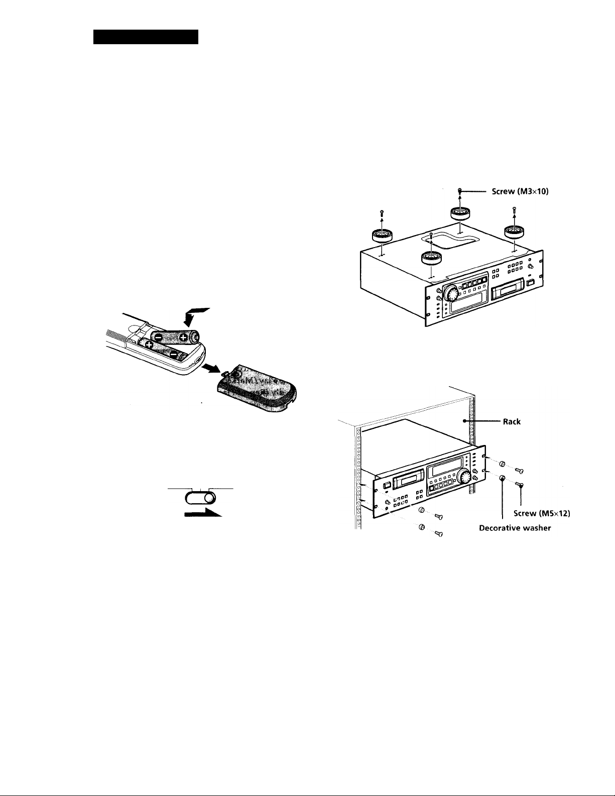
Inserting batteries into the remote
Insert two size-AA(R6) batteries, matching the + and on the batteries with the markings inside the battery
compartment.
Rack Mounting
You can install your deck in a 19-inch 3U-size rack. Be
sure to disconnect the deck from the wall outlet before
you install it.
1 Remove the four feet from the deck.
2 Insert the deck into the rack and secure it with the
supplied decorative washers and screws (M5xl2).
Before using the remote '
Set REMOTE on the front panel to WIRELESS.
REMOTE
WIRED OFF WIRELESS
'Q' When to replace the batteries
With normal use, batteries should last for about 6
months. When the remote no longer operates the deck,
replace both batteries.
Notes
• Do not leave the remote near an extremely hot or humid
place.
• Do not drop any foreign matter into the remote casing,
particularly when replacing the batteries.
• Do not expose the remote sensor to direct sunlight or
illumination as doing so may cause malfunction.
• When not using the remote for an extended period of time,
remove the batteries to avoid possible damage from
battery leakage and corrosion.
Note
Do not reattach the screws directly after removing the four
feet. Put the screws and the feet in a safe place for
reattachmenrtn the future. Using longer or shorter screws ■
may damage the internal circuit board.
Page 5
Hooking Up the System
This section describes how to hook up your deck to an
amplifier, stereo mixer, or other digital audio
components. Be sure to turn off the power to each
component before making the connections.
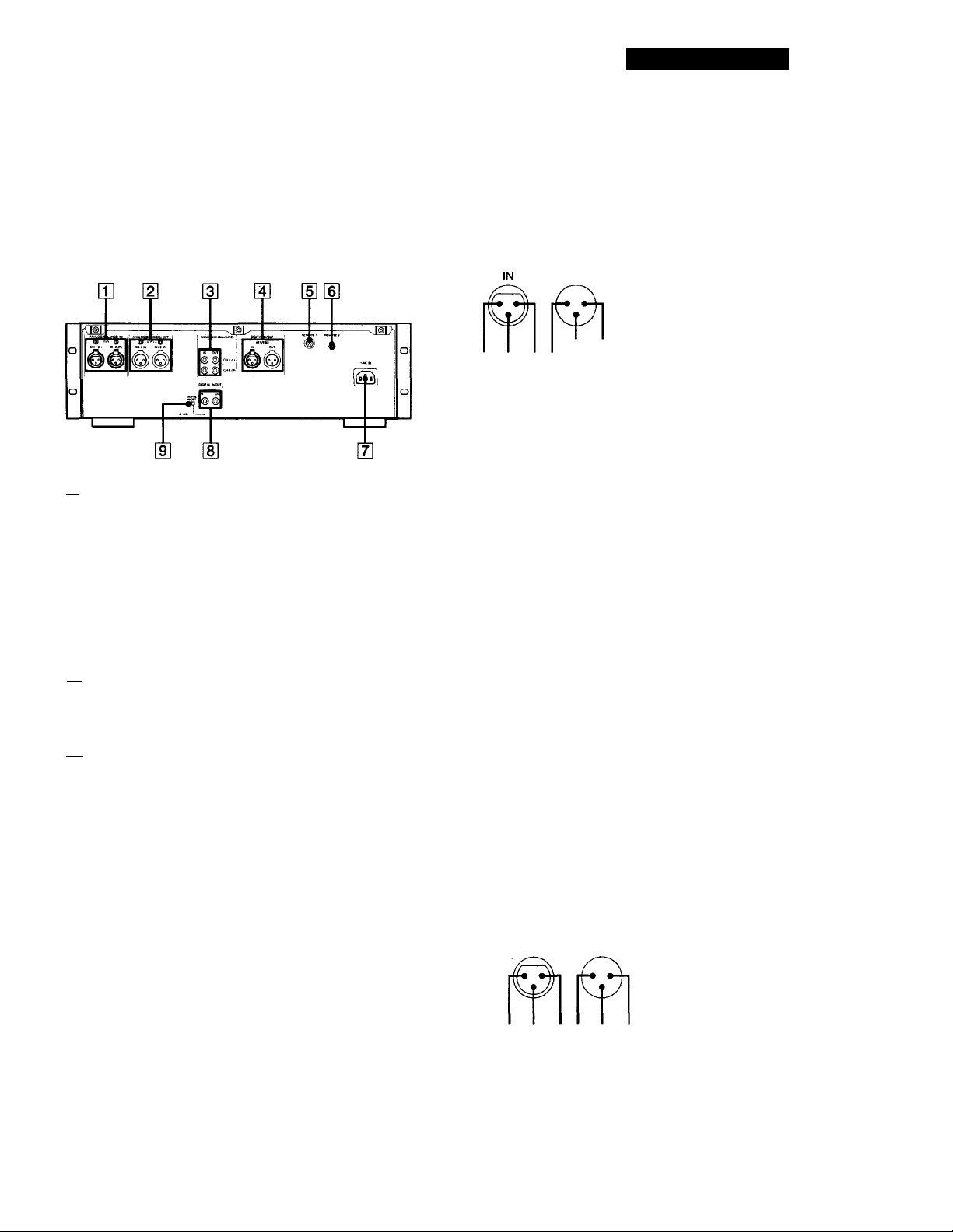
m ANALOG(BALANCE) IN connectors/
ANALOG(BALANCE) IN LEVEL controls
[2] ANALOG(BALANCE) OUT connectors/
ANALOG(BALANCE) OUT LEVEL controls
Getting Started
Analog connections
For connections through the ANALOG(BALANCE) IN/OUT connectors
Use XLR balanced cables.
ANALOG(BALANCE) IN/OUT pin polarity
OUT
1;GND
2:HOT
3:COLD
23-11 3 2
The analog input/output reference level adjustment
The analog input/output reference level during recording or
playback is factory set to +4 dBs within a range of -20 dB to
the full bit level for both input and output.
To lower the reference level, use a screwdriver to adjust the
ANALOG(BALANCE) IN/OUT LEVEL controls on the rear
panel for both CH-1 (L) and CH-2 (R). You can adjust the
reference level in a range of +4 dBs to -12 dBs. Make sure to
set the REC LEVEL CH-1(L)/2(R) controls on the front panel
to the center point before making this adjustment.
[3] ANALOG(UNBALANCE) IN/OUT connectors
g] DIGITAL AES/EBU IN/OUT connectors
[si REMOTE 1 connector (For parallel remote)
[6] REMOTE 2 connector (For serial remote)
[tI AC IN socket
[S DIGITAL COAXIAL IN/OUT connectors
[9] DIGITAL IN/OUT switch
For connections through the ANALOG(UNBALANCE) IN/
OUT connectors
Use phono-plug audio connecting cords.
Digital connections
Use the DIGITAL IN/OUT switch on the rear panel to
select the input/output connectors for digital signals.
Set the switch to AES/EBU to select the DIGITAL
AES/EBU IN/OUT connectors; set it to COAXIAL to
select the DIGITAL COAXIAL IN/OUT connectors.
For connections through the DIGITAL AES/EBU IN/OUT
connectors
Use XLR balanced cables for digital connections.
AES/EBU IN/OUT pin polarity
IN OUT
1;GND
2:HOT
3:COLD
1 1
For connections through the DIGITAL COAXIAL IN/OUT connectors
Use coaxial digital connecting cords.
Page 6

Getting Started
Other connections
To connect a switch box through the REMOTE 1 connector
Refer to "Remote Control Function Using a Parallel Remote
Connector" on page 28.
To connect the optional remote through the REMOTE 2 connector
Refer to "The Optional Remote RM-D750" on page 26.
Connecting AC power cord
Connect the AC power cord (supplied) to the AC IN
socket on the rear panel and connect the plug on the
other end to a wall outlet.
Where do I go next?
Now you're ready to use your deck.
For basic operations, go to pages 9 toll; for advanced
operations, go to pages after 12.
Digital Interface
Digital input and output connectors
• The following table shows signal formats that
correspond to the input and output connectors on
the deck.
• The DIGITAL COAXIAL IN connector accepts not
only the consumer version of the IEC-958
international digital audio interface standard, but
also the broadcasting studio version of the IEC-958
standard used by such DAT decks as the PCM-2300,
PCM-2700 or PCM-2700A.
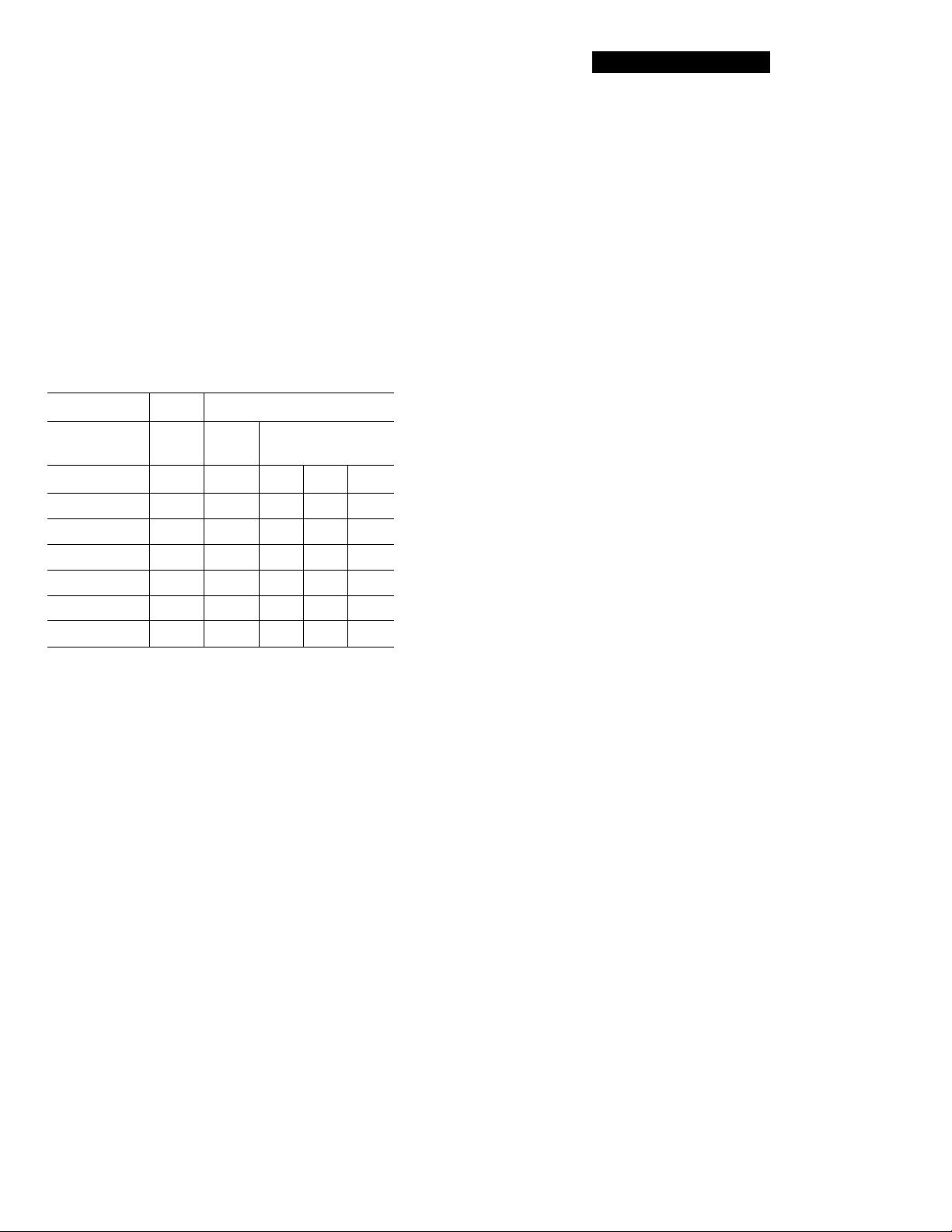
Type
DIGITAL
AES/EBU
DIGITAL
COAXIAL
Input connector Output connector
AES/EBU format
IEC-958 for
consumer use
IEC-958 for
broadcasting studio use
AES/EBU format
IEC-958 for consumer
use
Copy information during recording
• Copy information that is recorded on tape during
recording varies according to the input connector
used and the signal format, as shown in the table
below.
• In the case of AES/EBU and the IEC-958 for
broadcasting studio use, the digital signal carries no
copy information.
• As for the IEC-958 for consumer use, three types of
copy information exists: copying possible, firstgeneration copy p>ermitted, and copying prohibited
(Serial Copy Management System).
input Signal
connector format
DIGITAL
AES/EBU-
DIGITAL
COAXIAL
AES/EBU
IEC-958 for
broadcasting
studio use
IEC-958 for
consumer use
Copy
information
carried by on this
digital signal deck
None
None
Permitted Possible
Eirstgeneration
only
Prohibited Possible Prohibited
Recording
capability
Possible
Possible Determined
Possible
Copy
information
recorded on
tape
Determined
by menu
setting (pages
24 and 25)
by menu
setting (pages
24 and 25)
Permitted
(ID 6:00)
Prohibited
(ID 6:10)
(ID 6:10)
ANALOG
(BALANCE/
UNBALANCE
—
Possible
Determined by
menu setting
(page 24)
Page 7

Writing start IDs automatically during recording
• When "AUTO" appears in the display during
recording, the automatic writing of start IDs takes
place according to the input connector used and the
signal format, as shown in the table below.
• The condition for the automatic writing of start IDs
differs according to the category code in the digital
signal, such as an audio input level signal, a DAT
start ID code, or a Q-code from a CD track (see pages
24 and 25 ).
O: automatic writing possible
x; automatic writing prohibited
Getting Started
Input signal Signal format
DIGITAL
AES/EBU
DIGITAL
COAXIAL
(Category
code)
AES/EBU
IEC-958 for
broadcasting
studio use
IEC-958
consumer
'Jse (Other)
ANALOG
a) If the input level remains under the level set in the "L-SY
TH" menu longer than the time set in the "L-SY BK" menu
(see page 24), the deck writes a start ID when the input
level rises above that level.
b) DAT skip IDs are automatically written in the same way.
c) Only when connected to the PCM-2600, PCM-2800, PCM-
R500 or PCM-R700. When the connected decks consist of
a PCM-R500 or PCM-R700, select "on" in the "AES S-ID"
menu of the playback deck.
dlOnly when connected to the PCM-2300, PCM-2700, or
PCM-2700A.
e) Some CD players do not output track information (Q-
code) in the digital signal.
—
Automatic writing according to
audio input DAT start Q-code from
level ID ‘■1 a CD track
O O"'
O
QJI
o o
(CD)
o
o
o
X
X X
X X
X
X
X
Qel
Digital signal lock range
• The lock range of a digital signal (signal reception
range) is about ±0.1% for a sampling frequency of 48
kHz, 44.1 kHz, or 32 kHz. Variable pitch signals are
not receivable.
• When4he digital input sampling frequency
information does not match the actual sampling
frequency, it is possible to record that signal if you
change the REC MODE switch on the front panel to
the actual sampling frequency of the signal.
Page 8
Getting Started
Setting the Clock
Your deck has a built-in clock to keep track of the
current date and time. Once you set the date and time
by the menu settings, this information will be recorded
on the tape along with the audio signal during
recording, allowing you to check the recording date
time of the tape during playback at a later time.
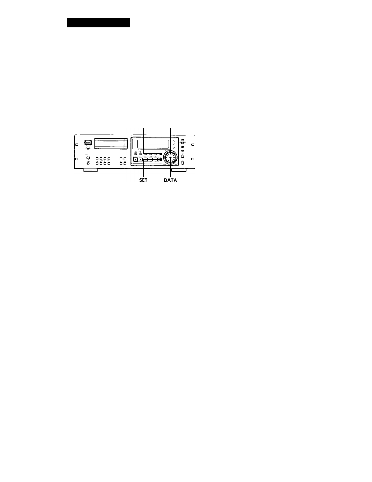
MENU SHUTTLE
1 With the deck stopped, press MENU.
The menu appears in the display.
Notes
• When you first set the clock after unpacking the deck,
" '
----------
" will appear when you press the SET button in
step 3. This is normal. Set the clock according to the
procedures above.
• Your deck uses a back-up battery to keep the clock
running when the power is turned off. The life of the
battery under normal use is approximately seven years.
When the battery starts to run down, the clock will stop
operating normally. When this occurs, have the battery
replaced (for a fee) at your dealer or nearest Sony Service
Center .
2 Turn SHUTTLE to display the "CLK-SET" menu.
3 Turn DATA to display "on" and press SET.
The year indication flashes.
4 Turn DATA to decrease or increase the displayed
year, then press SET.
The year indication stops flashing and the month
indication begins to flash.
’96'-:itei9 sp
5 Repeat step 4 until all items have been set.
After setting the seconds, press SET to start the
clock.
The day of the week is set automatically and is displayed as follows:
Sunday: "SU", Monday: "MO", Tuesday: "TU",
Wednesday: "WE", Thursday: "TH", Friday: "FR",
Saturday: "SA".
To display the date or time
See "About the Display" on page 16.
Q’ You can specify the format (12-hour or 24-hour) for
the time display, and display order for the date
display.
For details, see "ODER" or "DATEHOUR" on page 25.
For more accurate time recordings
Adjust the clock once a week.
8"
Page 9
Basic Operations
Playing a Tape
2
See pages 5 and 6 for hookup information.
To use headphones
Connect them to the PHONES
connector. Use PHONE LEVEL
to adjust the volume.
3 4
Turn on the amplifier and set the source selector to the position
1
for DAT.
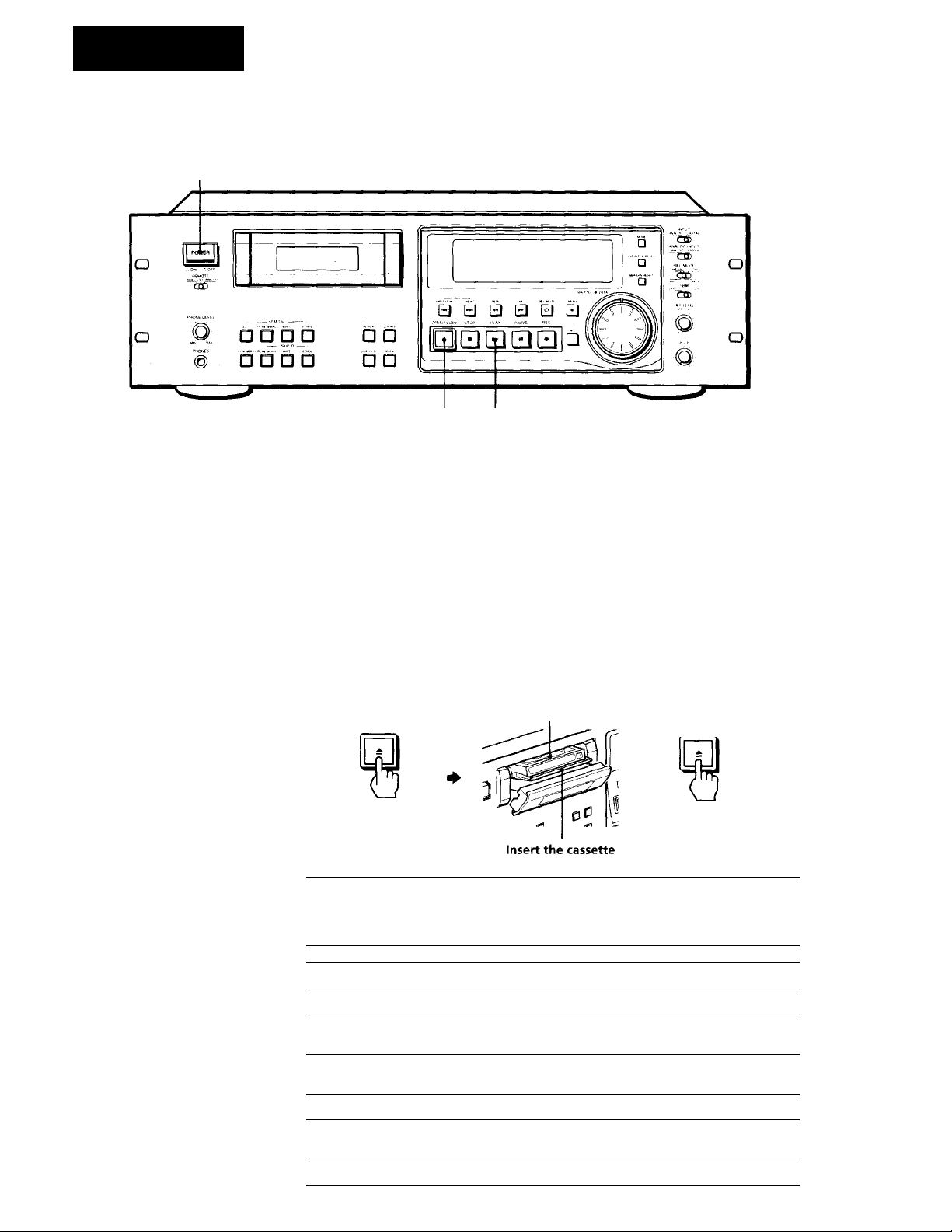
Press POWER.
Make sure that the KEY PROTECT switch is set to OFF (PCMR700 only) (see page 28).
Press OPEN/CLOSE ^ and insert a cassette.
Window side up
OPEN/CUOSE
A Press PLAY ► .
"T The deck starts playing.
until it clicks.
Adjust the volume on the amplifier.
OPENiCLOSE
Do not close the cassette
holder without pressing
OPEN/CLOSE ±.
■
To Press
Stop playing STOP ■
Pause playing PAUSE M. Press the button again or press PLAY
Go to the next track or the
preceding track
Fast-forward or rewind
Fast-forward or rewind while
monitoring the sound
Take out the cassette
► to resume play.
NEXT or PREVIOUS
FF ► ► or REW when the deck is stopped
FF ► ► or REW during playback. Release the
button to resume normal playback.
OPEN/CLOSE at after stopping playing
Page 10
Basic Operations
Recording on a Tape
3 8 6
See pages 5 and 6 for hookup information.
Turn on the amplifier and play the program source you want to
1
record.
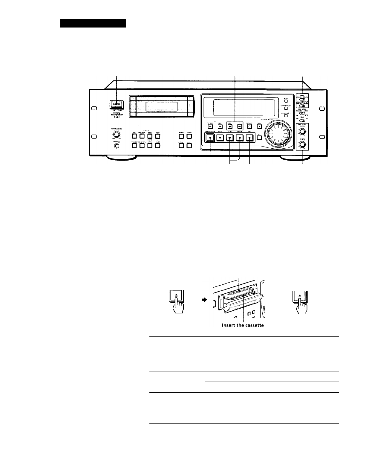
Press POWER.
Make sure that the KEY PROTECT switch is set to OFF (PCMR700 only) (see page 28).
Press OPEN /CLOSE — and insert a cassette.
Window side up
OPEN/CLOSE
until it clicks.
A Use INPUT, ANALOG INPUT, and DIGITAL IN/OUT to select
OPEN/CLOSE
Do not close the cassette
holder without pressing
OPEN/CLOSE ±.
"T the corresponding input connectors.
10"
To record through
ANALOG
(BALANCE) IN
ANALOG
(UNBALANCE) IN
DIGITAL AES/EBU
IN
DIGITAL COAXIAL INDIGITAL
* The DIGITAL IN/OL'T switch is loc.itod on the ro.ir panel (see page 5).
INPUT
ANALOG BALANCE
ANALOG
DIGITAL
Positions of the switches
ANALOG INPUT DIGITAL IN/OUT*
UNBALANCE
—
—
—
—
AES/EBU
COAXIAL
Page 11
If "UNLOCK" appears in the
display
The program source is not
connected to the deck
properly or is not turned on.
Make sure that the program
source is properly connected
or turned on.
Basic Operations
Locate the position where you want to start recording.
To record from the beginning of the tape
Press REW to rewind the tape to its beginning.
To record from the end of the recorded portion
1 Press REW to rewind the tape to its beginning.
2 Press FF
The deck locates the end of the recorded portion on the tape
and stops automatically.
Press REC #.
The deck changes to recording pause.
Recording does not start yet.
Q* To adjust the recording level
more accurately
While monitoring the sound,
turn REC LEVEL CH-1 (L)/2
(R) so that the recording level
on the peak level meters is at
maximum level without
entering the OVER range.
Maximum level
Remains unlit
The segments of the peak
level meters corresponding to
the maximum signal strength
remain lit longer than normal.
The MARGIN indication
shows the margin between
maximum signal strength and
OdB, changing each time a
stronger signal.
If the level exceeds OdB
The segments under "OVER"
light up, and "O.OdB" flashes
in the display. If these
segments light steadily,
sound distortion may occur.
To avoid'this, keep the
recording level between
-12dB and OdB.
To reset the margin
indication
Press MARGIN RESET. The
margin indication changes to
- dB".
When recording an analog input signal, adjust the recording
level with REC LEVEL CH-1(L)/2(R).
The recommended recording level is the center point.
Press PAUSE II or PLAY
I
8
Recording starts.
Start playing the program source.
When the tape reaches the end, the deck rewinds it
automatically to its beginning and stops (Auto Rewind).
To
Stop recording STOP«
Pause recording
Take out the cassette OPEN/CLOSE-A after stopping recording
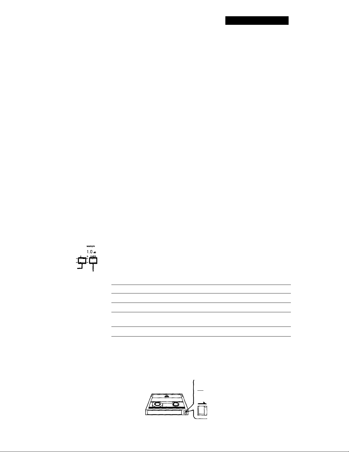
To prevent accidental erasure
Slide the record-protect tab to the left as shown in the illustration
below.
Press
PAUSE II. Press the button again
or press PLAY ► to resume recording.
Recording is
impossible (tl
IJIj impossible (the
hole is open).
Recording is
possible (the
hole is closed).
11'
Page 12
Advanced Recording Operations
Things You Should Know
Before Recording
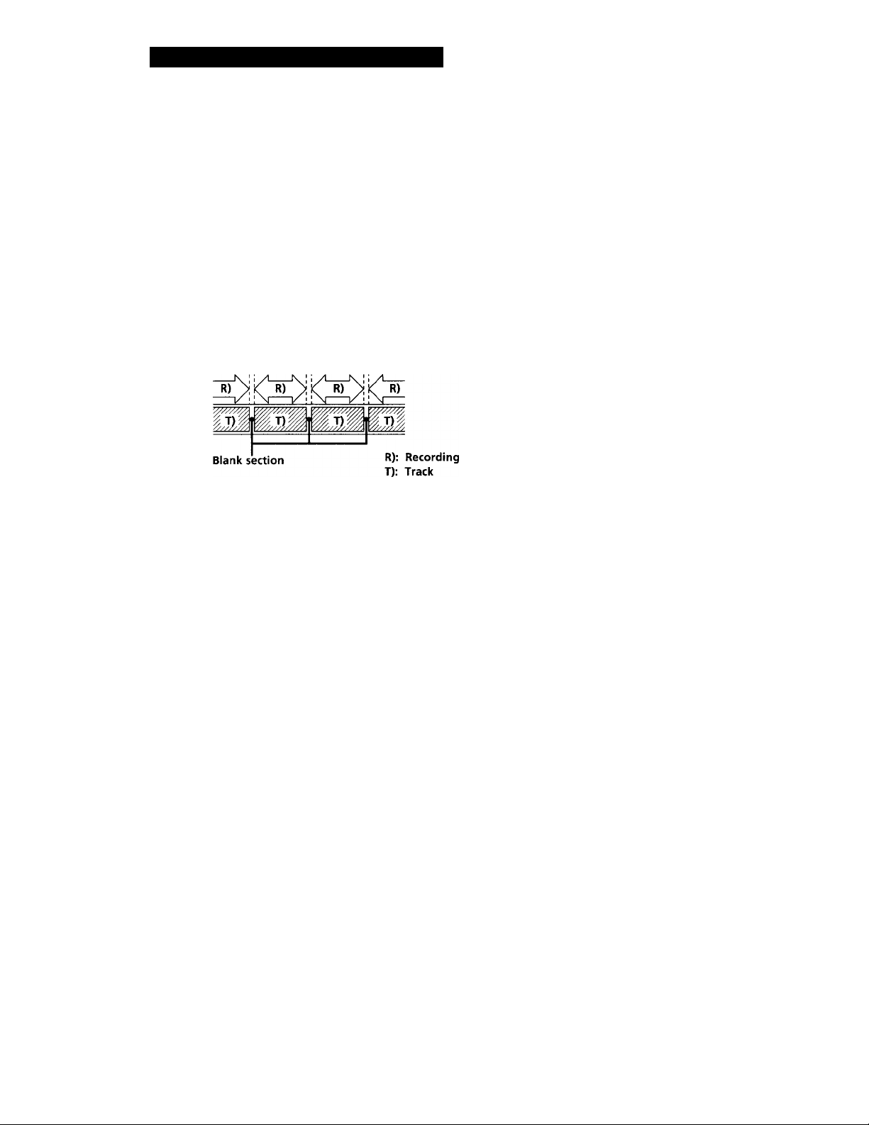
The difference between a blank section and a sound-muted section
The deck distinguishes between two kinds of silent
sections, which are respectively called a "blank
section" or "sound-muted section".
Blank section
This is a section on which no signal has ever been recorded.
Sound-muted section
This is a section on which a signal has been recorded but at a
level that is not audible.
R)
For accurate recording of absolute time codes
• If the tape is blank, make sure to start recording from the
beginning of the tape.
• Use the Record Muting function (see page 14) to insert
spaces between tracks. Do not advance the tape with the
PLAY ► or FF ► ► button.
• To start recording from the middle of a tape, use the End
Search function (see page 14) to locate the end of the
recorded portion. This will prevent the creation of blank
sections.
Lead-in area
When the deck is loaded with a new cassette tape and
it detects the leader tape, the deck can create a lead-in
area depending on the menu setting as shown in the
figure below. "BB" appears in the display for about 1
second at this time. The lead-in area can be
inadvertently erased on another DAT deck if you press
the REC # button to start recording from the
beginning of the tape without closing the cassette
holder first. To prevent this, press the OPEN/CLOSE
^ button to close the cassette holder before you start
recording.
Eor details on selecting the automatic creation of the
lead-in area and the frequency of the signals to be
recorded, see "BB-WRT" and "BB-FS"on page 25.
"BB" appears under PGM NO.
Starting point for
' recording
iM
Sound-muted
section
Important
Make sure no blank sections are created while you
are recording. The existence of blank sections
within recorded material will make search
operations using the PREVIOUS «◄/NEXT
buttons impossible or destroy the continuity of the
absolute time codes.
Absolute time codes
The absolute time indicates the elapsed time from the
beginning of the tape. Once recorded, the absolute
time codes cannot be re-written.
R): Recording
T): Track
Absolute time indication
Leader tape
0m01s OmOOs
Lead-in area
OmOls 0m02s
Track
If "EMPHASIS" appears in the display
The deck is recording a digital signal with emphasis (in
the higher frequencies). The recording will also
contain the same emphasis.
If the deck is left in recording pause for
more than 10 minutes
Recording pause will be released automatically and the
deck will stop for the sake of tape protectiort.
"SOURCE" will appear in the display of the PCMR500.
To resume recording, press the REC # button. The
deck will change to recording pause.
12^
Page 13
Setting the Recording Mode
You can select between two recording modes, standard
or long, in the following cases.
• When recording an analog input signal with the
INPUT switch set to ANALOG
• When recording a digital input signal with a
sampling frequency of 32 kHz with the INPUT
switch set to DIGITAL .
REC MODE
Set REC MODE to select the recording mode.
The following table shows the selectable recording
modes and corresponding REC MODE position and
sampling frequency for various input signals.
Advanced Recording Operations
'Q ' The counter in long-play mode
The displayed tape running time, absolute time and
remaining time on the tape are for standard-play mode.
Double the time to obtain the corresponding times for
long-play mode.
Note
Do not change the INPUT or REC MODE setting while
recording. This may cause an error in the "PGM TIME"
display.
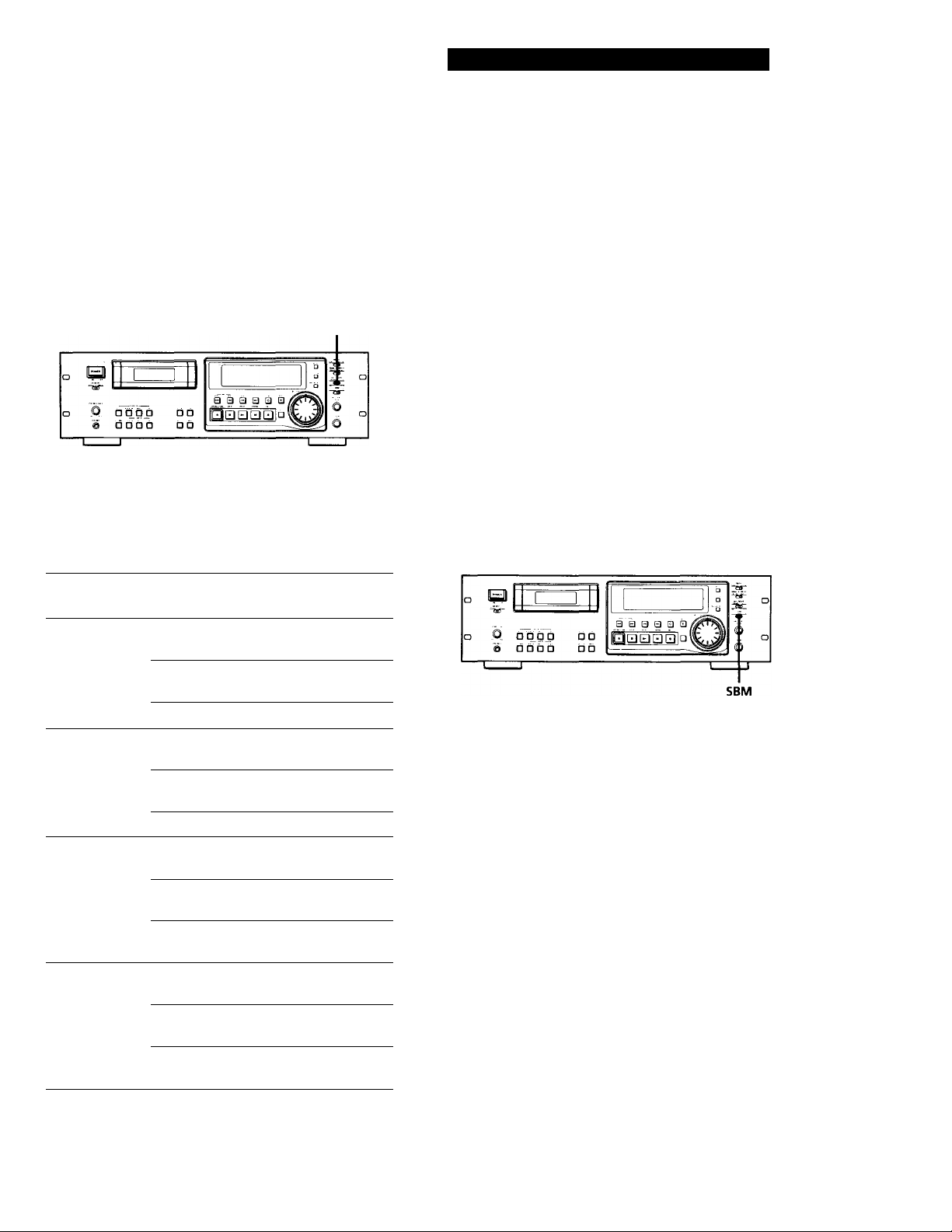
Using the SBM (Super Bit Mapping) Function
The SBM function uses the principles of human
hearing and noise-shaping technology to reduce
quantizing noise within the frequency band.
You can use the SBM function to record on analog
input signal only when the INPUT switch is set to
ANALOG and the REC MODE switch to STANDARD
(either 48kHz or 44.1kHz).
Input signal
Analog STANDARD
Digital (32kHz)
Digital (44.1kHz) STANDARD
Digital (48kHz)
-
REC MODE
position
(48k)
STANDARD
(44.1k)
LONG
STANDARD
(48k)
STANDARD
(44.1k)
LONG
(48k)
STANDARD
(44.1k)
LONG
STANDARD
(48k)
STANDARD
(44.1k)
LONG
Recording mode
Standard play
(48kHz)
■ Standard play
(44.1kHz)
Long play (32kHz)
Standard play
(32kHz)
Standard play
(32kHz)
Long play (32kHz)^
Standard play
(44.1kHz)
Standard play
(44.1kHz)
Standard play
(44.1kHz)
Standard play
(48kHz)
Standard play
(48kHz)
Standard play
(48kHz)
Set SBM to ON.
"SBM" appears in the display during recording using
the SBM function.
Note
The SBM function operates only during recording. The
improved sound produced by the SBM function, however,
can be enjoyed during playback, regardless of the SBM
switch position or the DAT deck being used.
The recording time in long-play mode (the REC MODE
switch set to LONG) is twice as long as standard-play
mode.
13'
Page 14
Advanced Recording Operations
Locating the End of the Recorded Portion (End Search)
When recording from the middle of a tape, use End
Search to locate the end of the recorded portion. This
will prevent the creation of a blank section on the tape.
FFI
Press FF ► ► with the deck stopped.
The deck locates the end of the recorded portion (the
beginning of the blank portion or the position of the
end ID), then stops.
The deck stops at the beginning of any blank section
that is 9 seconds or longer, or fast-forwards to the end
of the tape if the tape is blank.
'Q ' When you press the REC # button while in a blank
section
The deck rewinds the tape to the beginning of the blank
section and changes to recording pause. "BLANK" and
"WAIT" appear in'the display while the deck is
searching for the beginning of the blank section.
Note
End Search does not operate if you press the FF I
while in a blank section.
• button
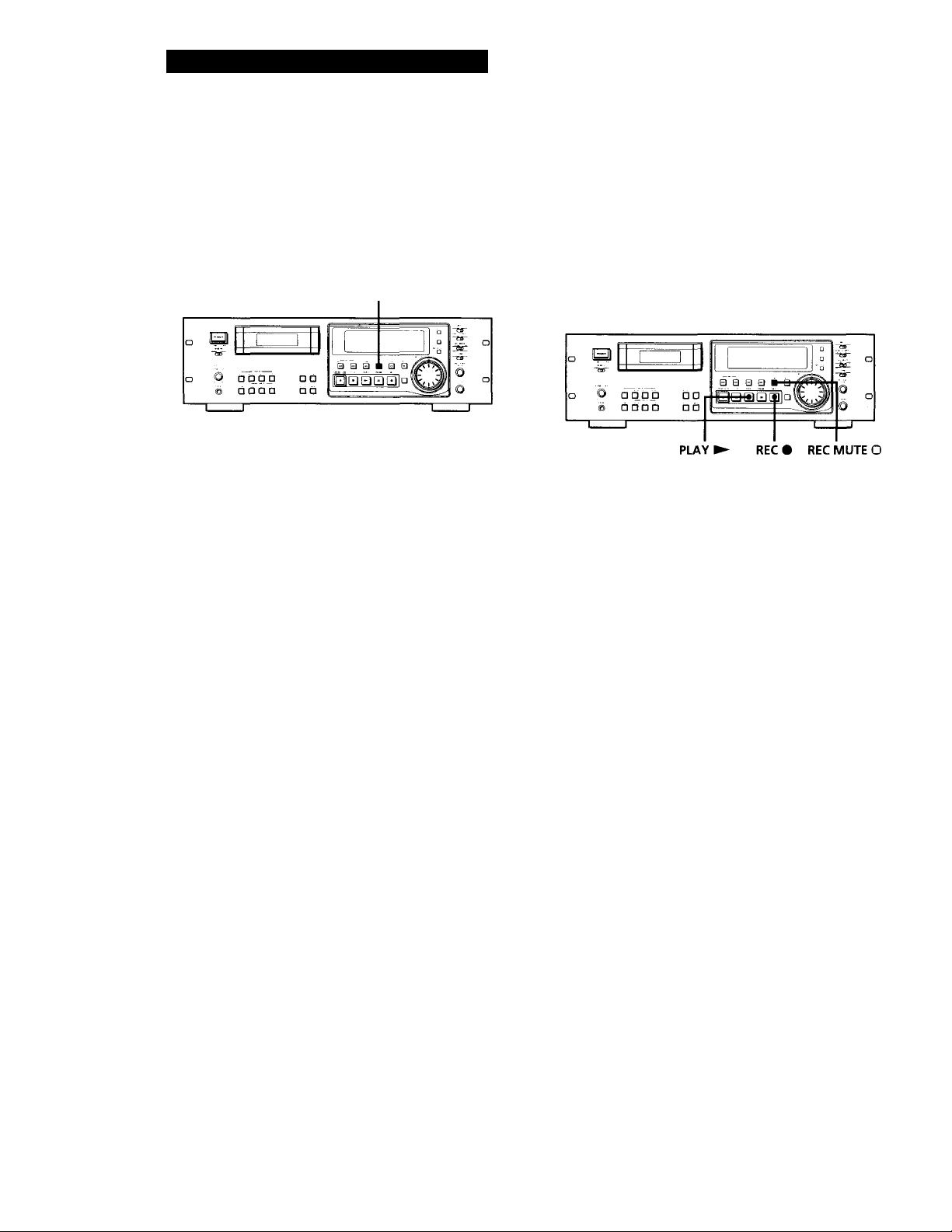
Inserting a Sound-Muted Section While Recording (Record Muting)
Use Record Muting to insert a space of about 0.5 to 9.5
seconds between tracks.
For details on setting the duration of the blank space,
see "REC MUTE" on page 24.
Press REC MUTE O where you want to insert a space
while the deck is recording or in recording pause.
"REC" in the display starts flashing and tape transport
continues, but no signal is recorded. After inserting a
space, II in the display stays on and the deck changes
to recording pause.
To insert a blank space (of a duration different from that preset by menu setting)
Hold down the REC MUTE O button as long as you want.
When you release the REC MUTE O button, II stays on and
the deck changes to recording pause.
When the preset duration has passed, "REC" begins to flash
faster and the MARGIN indication shows how long the REC
MUTE O button has been pressed.
To insert a blank space of a duration shorter than the preset value
Press REC # while "REC" is flashing. The deck starts
recording again.
14^
Note
If you do not create a sound-muted section at the beginning
of a tape, you may not be able to move or erase a start fD .
(see page 19) that is recorded within 2 seconds from the
beginning of the tape.
Page 15
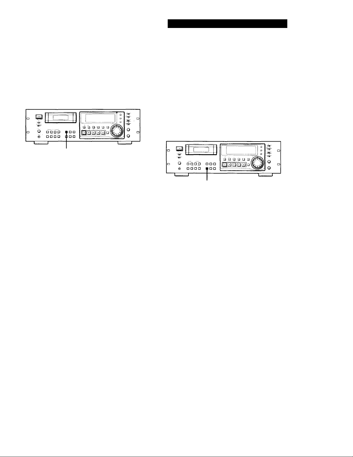
Advanced Recording Operations
Monitoring the Recorded Sound (Record Monitoring) (PCM-R700 Only)
You can compare the recorded sound with the sound
of the program source while recording.
INPUT MONITOR
While recording, press INPUT MONITOR to turn off
"INPUT" in the display.
The recorded sound is output.
Turns off.
To listen to the program source
Press INPUT MONITOR to turn on "INPUT" in the display.
Fade-in/Fade-out Recording (Fader) (PCM-R700 Only)
You can use the fader to fade-in the beginning of a
recording or fade-out the end of a recording. It's useful
when you want to start or end a recording in the
middle of a song.
You can specify the fade-in and fade-out durations of
0.5 to 9.5 seconds through the menu settings.
For details, see "FADE IN" and "FADE OUT" on page
25.
FADER
Fading in
Press FADER while the deck is in record pause mode.
"FADE IN" appears in the display and the time display
counts backward to "0.0s" as the fade-in takes place.
'Q' You can listen to the program source even when not
recording
Press INPUT MONITOR to turn on "INPUT" in the
display.
The program source is output when:
• the deck is stopped.
• fhe cassette is ejected.
The program source is not output when "INPUT" is
turned off.
Note
If you do any of the following operations while listening to
the program source, "INPUT" turns off and output of the
program source stops, and "INPUT" will not go on even you
press the INPUT MONITOR button:
• Start playback by pressing the PLAY ► button.
• Pause playback by pressing the PAUSE II button,
• Press the REW MM button.
• Press the FF ► ► button.
Fading out
Press FADER while the deck is recording.
"FADE OUT" appears in the display and the time
display counts backward to "0.0s" as the fade-out takes
place. After fading out, the deck automatically enters
record pause mode.
Note
Your deck has a digital fader that is capable of fading in or
out in 256 steps. Switching noise, however, may occur
during recording of low-level or single-frequency signals.
If this happens, use a fader on a component, such as a mixer,
connected to the deck.
15'
Page 16
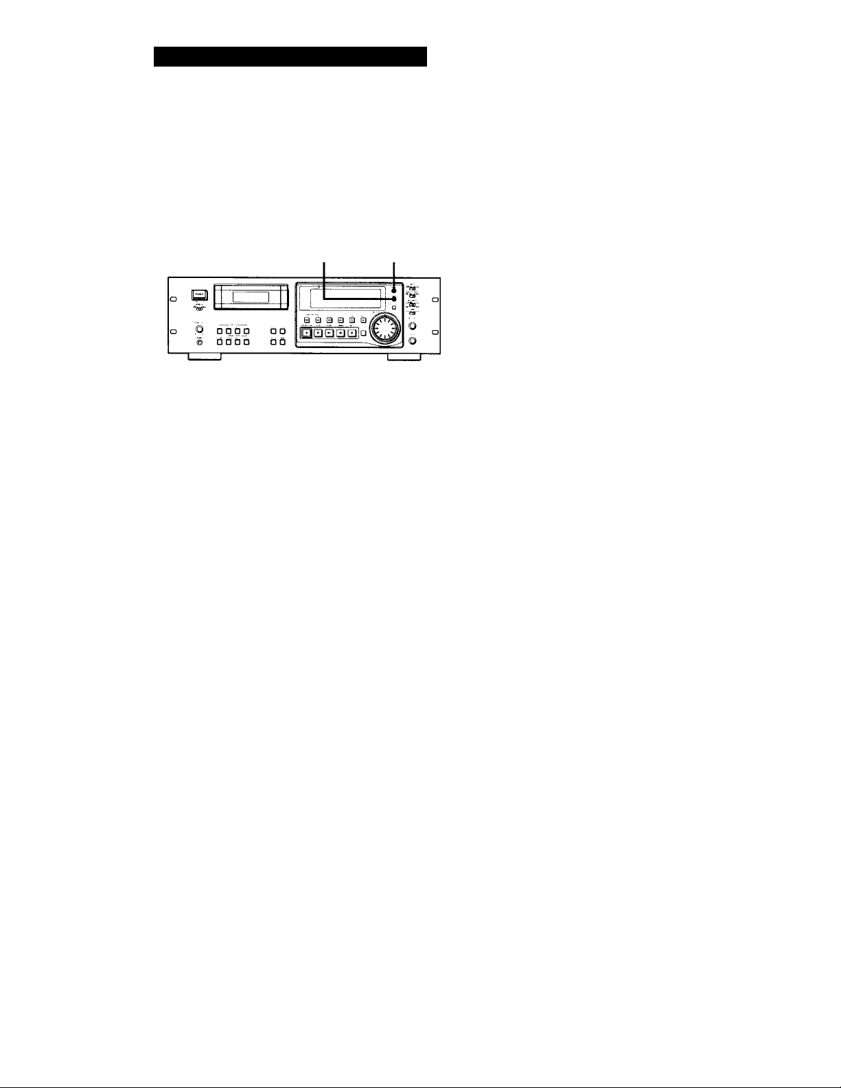
Advanced Playback Operations
About the Display
You can use the display to show the tape running time,
absolute time, playing time of the track, remaining
time on the tape, date and time of recording, and
current date and time.
The playing time of the track will not be displayed
when the "P-TMDISP" menu is set to (see page 25).
The date and time of recording and the current date and
time will not be displayed when the "DATEDISP" menu
is set to " (see page 25).
If this information is not recorded on the tape, nothing
will appear.
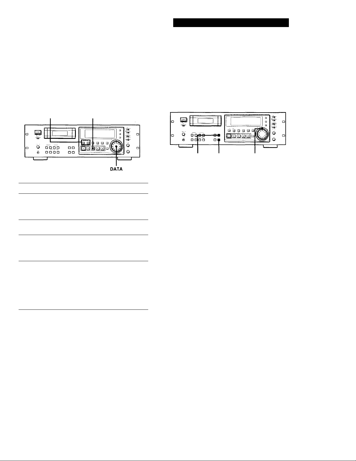
COUNTER RESET MODE
Press MODE repeatedly.
Each time you press the MODE button, the displayed
information changes as follows.
Absolute time
Playing time of
the track*
Remaining time
on the tape
8.20.
Press {y
3.15.
Press
1.00.
In the case of premastered tapes, the remaining time is to
the end of the recorded portion.
Press ^
Current date
and the day of
the week**
Current time**
’96 10 19 Sfl
Press
1 1.30.00. PIM
To reset the tape running time
Press COUNTER RESET.
When "DATE" appears in the display
"DATE" remains lit when the date and day of the week or
time of recording appears, and flashes when the current date
and time appears.
Notes
• When playing certain types of premastered tapes, "BB"
may appear momentarily in the display at the beginning
of the tape.
• The playing time of the track does not appear in the
following cases:
— When you start playing from the middle of the track
— During rewinding
• In standard-play mode, the remaining time on the tape
appears about 16 seconds after you start playing.
• The displayed remaining time may vary somewhat from
the actual remaining time, depending on the tape.
If "EMPHASIS" appears in the display
The deck is playing an audio signal recorded with
emphasis (in the higher frequencies). The deck,
however, plays the signal while automatically
deemphasizing it (with attenuation proportional to the
degree of emphasis).
"ERR" appears in the display for 5 seconds
or more
• The head is dirty. Clean the head with the DAT
cleaning cassette (see page 29).
• The cassette is defective or damaged.
16"
Date and the
day of the week
of recordingJJ^
Time of
recording^*
Tape running
time
Press
’94 11 11 FR
Press
10.13.26. PM
Press
5. 19.
Press
Page 17
Advanced Playback Operations
Locating a Track (AMS*/Direct
Access)
You can locate the tracks in a number of ways, but only
after you have recorded start IDs on the tape (see pages
19 to 23). To use Direct Access, program numbers
must be recorded on the tape (see pages 19 and 23).
PREVIOUS I I/NEXT I PLAY I
To locate Do the following:
The beginning of the next
or succeeding tracks
(AMS)
The beginning of the
current track (AMS)
The beginning of
preceding tracks (AMS)
By specifying the
program number of a
track (Direct Access)
* AMS = Automatic Music Sensor
If you enter the wrong program number during Direct Access
If you haven't pressed the PLAY ► button, turn the
DATA dial on the deck (or press the CLEAR button,
then enter the correct number on the remote).
If the deck detects a blank section of 9 seconds or more, end ID, or the end of the tape
The deck rewinds the tape automatically to its
beginnirtg and stops (Auto Rewind).
y You can make the deck start playing automatically
from the beginning of the tape after rewinding
(Auto Play)
Press the PLAY ► button while holding down the
REW button.
Press NEXT as many times
as you want while playing. For
example, to locate the second
track ahead, press twice.
Press PREVIOUS once
while playing.
Press PREVIOUS as many
times as you want while playing.
For example, to locate the second
track behind, press three times.
1 While the deck is playing or
stopped, turn DATA on'the
front panel until the program
number you want appears in
the display (or enter the
program number with the
number buttons on the remote).
2 Press PLAY ► .
Locating a Point (Shuttle Play/ Mark & Locate)
You can locate a specific point by playing back at a
different speed or recording the absolute time code at
the point to be located later.
LOCATE MARK
To locate
A track using variable
speed play (Shuttle Play)
A particular point on a
tape (Mark & Locate)
Q' Playback speed during Shuttle Play
During Shuttle Play, you can vary the playback speed
from ±0.5 to ±8 times the normal playback speed (or ±1
to ±8 times the normal playback for material recorded
in long-play mode), depending on the angle and
direction of the SHUTTLE dial. Turn the dial clockwise
for forward playback or counterclockwise for reverse
playback.
The playback speed will be ±8 times normal speed
playback when you turn the dial to the left or right
fully.
Note
Shuttle Play should be used only when necessary since
prolonged use may damage the tape and drum.
Q The point memorized using the Mark & Locate
function will be erased when:
— you take out the cassette.
— vou turn off the deck.
Do the following;
While the deck is playing, stopped,
or paused, turn SHUTTLE.
• If the deck was playing or
stopped, the deck starts to play
when you release the SHUTTLE
dial.
• If the deck was paused, the deck
pauses when you release the
SHUTTLE dial.
While the deck is playing or
stopped, press MARK. The
absolute time of the point
where you pressed the button
appears and flashes three
times.
Press LOCATE. The deck
locates the point and stops.
SHUTTLE
17'
Page 18
Advanced Playback Operations
Playing Tracks Repeatedly (Repeat Play)
You can play a specific track or all the tracks on the
tape repeatedly.
REPEAT
Playing all tracks repeatedly
Press REPEAT repeatedly while playing a track until
"REPEAT" appears in the display.
The deck will play all tracks 5 times, then stops.
If the deck detects either of the following during
Repeat Play, it will rewind the tape to its beginning
and start playing again.
— A blank section of 9 seconds or more
— The end of the tape or the end ID
To stop playing all tracks repeatedly
Press REPEAT repeatedly until "REPEAT" disappears.
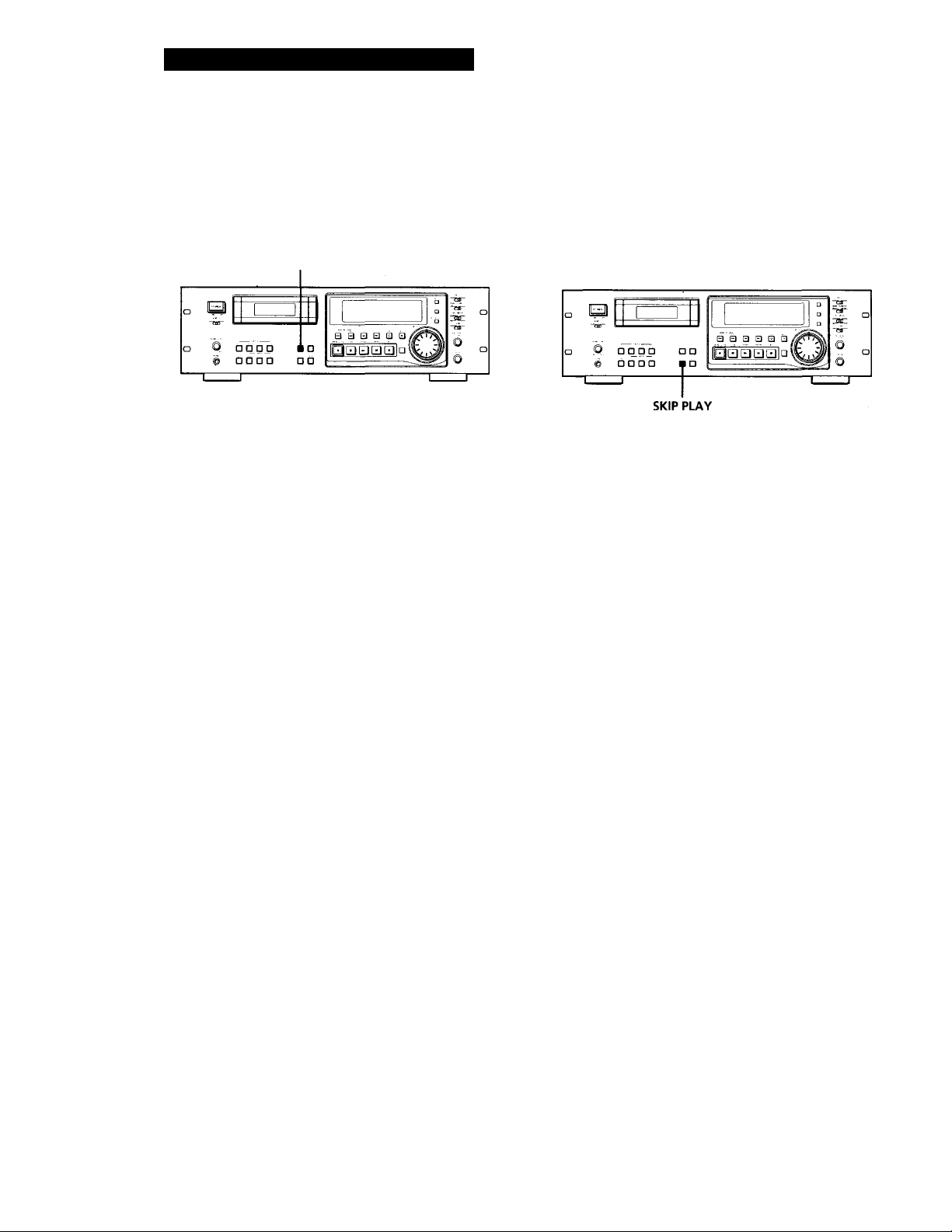
Playing Tracks Skipping Specific Portions During Playback (Skip Play)
Please note that skip IDs (see page 19) must be written
on the tape before you can use Skip Play.
Press SKIP PLAY.
"SKIP PLAY" appears in the display. When the deck
detects a skip ID, it fast-forwards the tape to next start
ID, then resumes playing.
To cancel Skip Play
Press SKIP PLAY.
"SKIP PLAY" disappears.
Note
Skip Play is canceled when you take out the cassette.
Note
Repeat Play of all tracks is canceled when you take out the
cassette.
Playing a track repeatedly
Press REPEAT repeatedly while playing the track you
want to repeat until "REPEAT 1" appears in the
display.
The deck plays the current track 5 times and then
stops.
If the deck detects any of the following during Repeat
Play, it will rewind the tape to the start ID of the
current track and starts playing again from that
position.
— The next start ID
— A blank section of 9 seconds or more
— The end of the tape or end ID
— A skip ID with Skip Play activated
To stop playing a track repeatedly
Press REPEAT repeatedly until "REPEAT 1" disappears.
Note
Repeat Play of a single track is canceled when you take out
the cassette.
18'
Page 19
Advanced Playback Operations
Writing Sub Codes
Fade-in/Fade-out Playback (Fader) (PCM-R700 only)
You can use the fader to fade-in the beginning of
playback or fade-out the end of Playback. It's useful
when you want to record from DAT.
You can specify the fade-in and fade-out durations of
0.5 to 9.5 seconds through the menu settings.
For details, see "FADE IN" and "FADE OUT" on page
25.
FADER
Fading in
Press FADER while the deck is in play pause mode.
"FADE IN" appears in the display and the time
display counts backward to "0.0s" as the fade-in takes
place.
Fading out
Press FADER during playback.
"FADE OUT" appears in the display and the time
display counts backward to "0.0s" as the fade-out
takes place. After fading out, the deck automatically
enters play pause mode.
Note
Your deck has a digital fader that is capable of fading in or
out in 256 steps. Switching noise, however, may occur
during playback of low-level or single-frequency signals.
If this happens, use a fader on a component, such as a mixer,
connected to the deck.
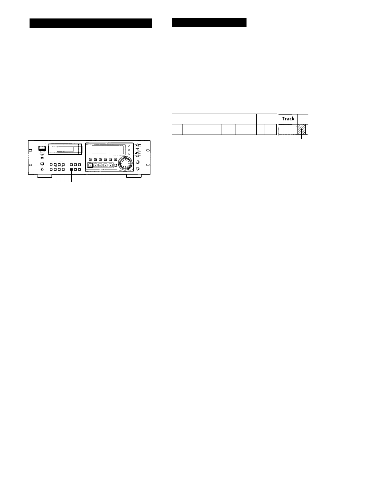
About Sub Codes
In the DAT format, control codes, or sub codes, such as
start IDs, skip IDs, and end ID can be recorded on the
tape with the audio signal. Since sub codes are written
on the tape separately from the audio signal, they have
no effect on the audio signal.
Track
.1 i I 1
Start IDs
Start IDs indicate the start of a track, and therefore
allow you to locate the position of a track precisely.
The start IDs are 9 seconds in length (18 seconds in
long-play mode) to enable easy detection during fastforwarding or rewinding.
Program numbers
Program numbers serve as track numbers. Occupying
the same position as start IDs, a program numbers
allow you to locate specific tracks or play tracks in a
specific order.
Skip IDs
Skip IDs indicate tracks or recorded portions that are to
be skipped while playing. Skip IDs are 1 second in
length (2 seconds in long-play mode).
End ID (when the optional remote is used)
An end ID indicates the end of a recording. An end ID
is 9 seconds in length (18 seconds in long-play mode).
When an end ID is detected during playback, playback
stops and the deck rewinds the tape to its beginning. If
an end ID is detected during fast-forwarding, the tape
stops at that point and deck becomes ready for
recording from that point.
You can write and erase an end ID only with the
optional remote RM-D750. For details, see "Writing
and Erasing an End ID" on page 27.
Track
Skip ID
Track 1
Start ID
End ID
Notes
• The OPEN/CLOSE A, STOP ■ and PAUSE II buttons do
not work during the writing or erasing of sub codes.
• Writing and erasing of sub codes and renumbering of
program numbers are impossible if the record-protect hole
on the DAT cassette is open (see page 11).
19'
Page 20
Writing Sub Codes
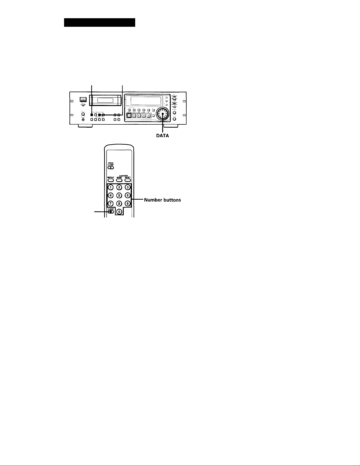
Writing Start IDs During
Recording
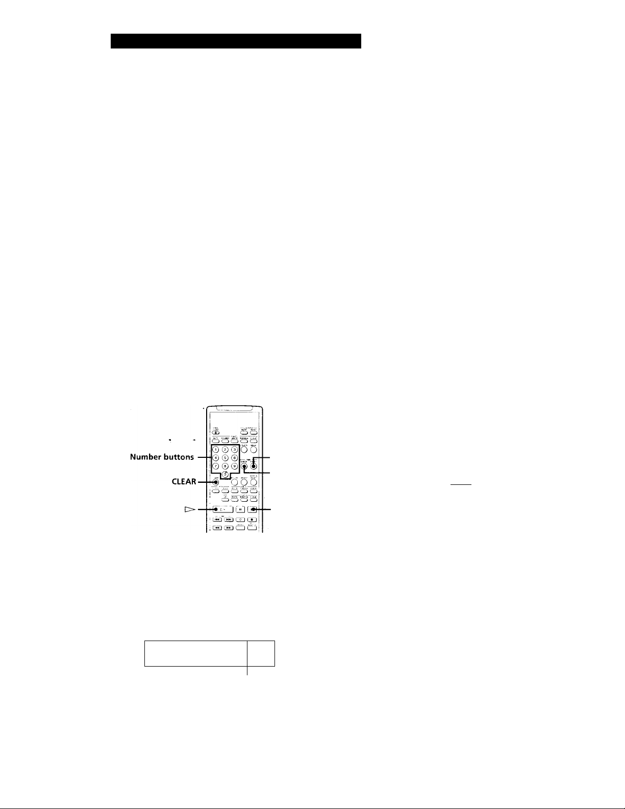
START ID AUTO START ID WRITE
Writing program numbers during recording
Program numbers occupy the same positions as the
start IDs and are determined by depending on the
following conditions:
When a program number is displayed
The next program number rises by one above when the next
start ID is written.
When no program number is displayed appears
instead)
Program numbers are not written even when start IDs are
written. To write program nunbers, rewind the tape to the
nearest start ID to display the program number, and then
locate the position where you want to start recording.
Specifying the first program number to be
assigned
1 Pause recording.
CLEAR
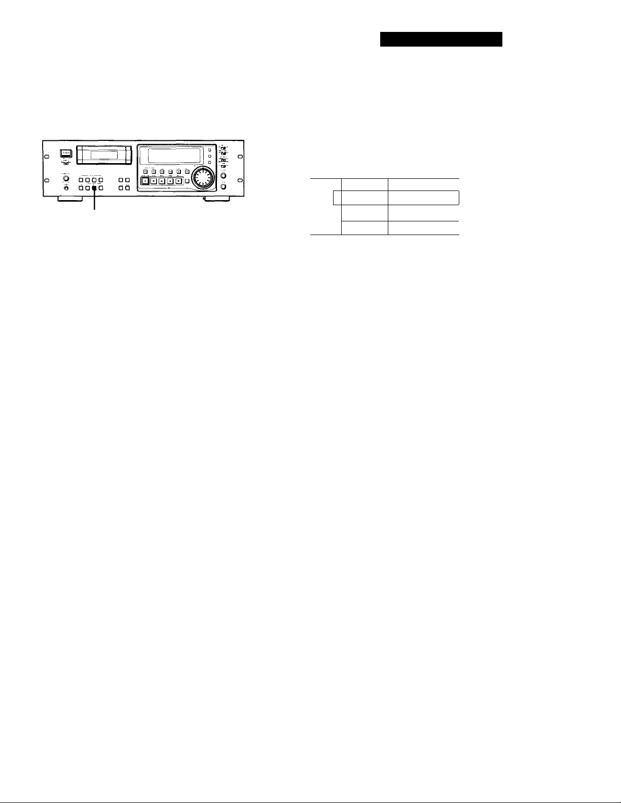
Writing start IDs manually during recording
Press START ID WRITE.
"ID WRITE" appears in the display for a few seconds
and the start ID is written on the tape. "START ID"
flashes in the display during this time.
ID U RI TE
Note
The interval between start IDs must be more than 18 seconds
(36 seconds in long-play mode). If the interval is less than 18
seconds (or 36 seconds), the deck may fail to detect the
second start ID while playing a tape.
Writing start IDs automatically during
recording
Press START ID AUTO repeatedly until "AUTO"
appears in the display.
2 Press the number button(s) on the supplied
remote, or turn DATA to input the first program
number.
The number appears in the display.
To cancel the number, press the CLEAR button on
the supplied remote.
3 Start recording.
A start ID and the assigned program number are
written simultaneously.
Note
During automatic start ID writing the positioning of some
start IDs may be inaccurately or inappropriately positioned
away from the beginning of the track. If this happens, you
can reposition or erase the start IDs later (see "Accurate
positioning of sub codes" on pages 21 and 22, and "Erasing
Sub Codes" on page 23).
20^
For details on the condition for the automatic writing
of start IDs, see "Writing start IDs automatically during
recording" on page 7, and "Menu Operations" on
pages 24 and 25.
Page 21
Writing Sub Codes
Writing Skip IDs During Recording
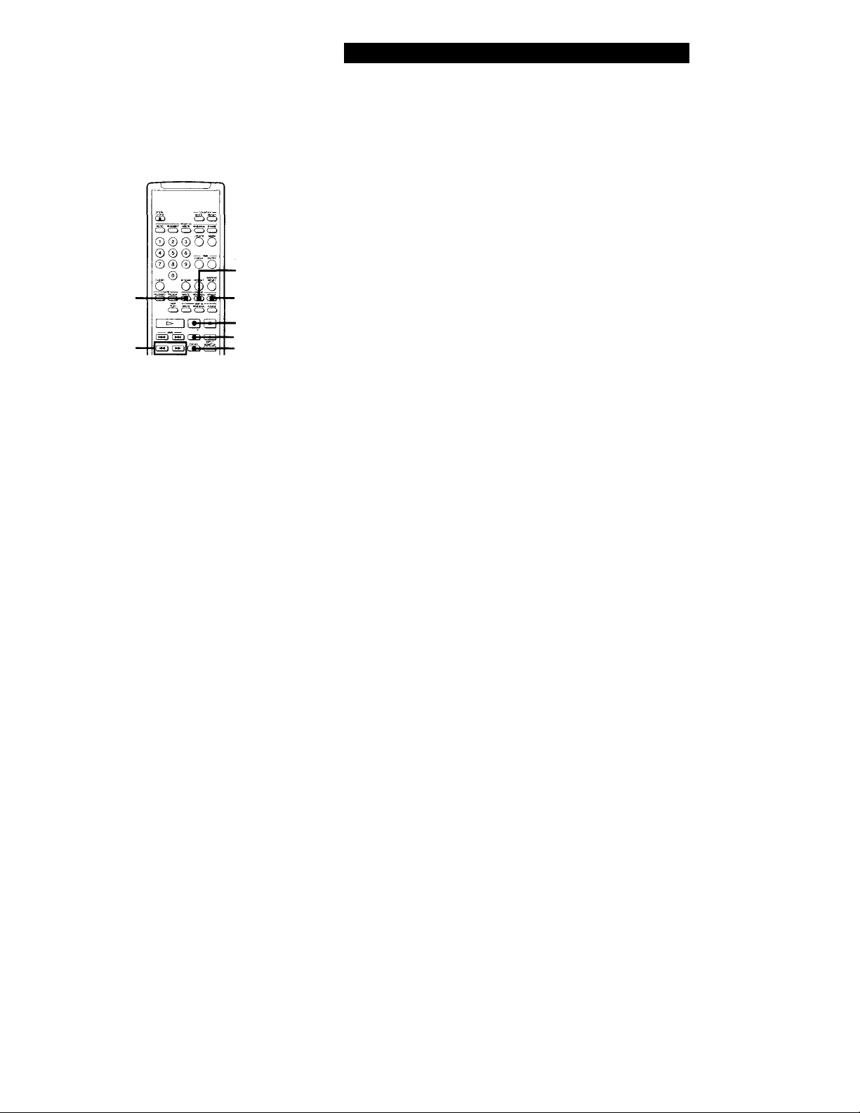
SKIP ID WRITE
Writing skip IDs manually during recording
Press SKIP ID WRITE.
"ID WRITE" appears in the display for a few seconds
and the skip ID is written on the tape. "SKIP ID"
flashes in the display during this time.
ID ii) RI TE
Writing Sub Codes During
Playback
You can write start IDs or skip IDs during playback.
START ID START ID
REHEARSAL WRITE
1 1
a a la ai a □
■ i?i h n
© □ 1
SKIP ID
REHEARSAL
Press START ID WRITE or SKIP ID WRITE.
"ID WRITE" appears in the display for a few seconds
and the specified ID is written on the tape at the point
you pressed the button.
Accurate positioning of sub codes
(Rehearsal function)
1 During playback, press REHEARSAL
corresponding to the ID you want when you
arrive at the proper position.
"REHRSL" appears, the corresponding ID
indication flashes in the display and the Rehearsal
function repeats a 3-second portion containing the
selected position. The repeated portion plays
back 8 times, with the remaining number of times
appearing to the right of the "REHRSL". After 8
times, the deck stops.
In the case of a start ID, the 3-second repeated
portion starts from the point where you pressed
the REHEARSAL button.
In the case of a skip ID, the 3-second repeated
portion ends at the point where you pressed the
REHEARSAL button.
SKIP ID
WRITE
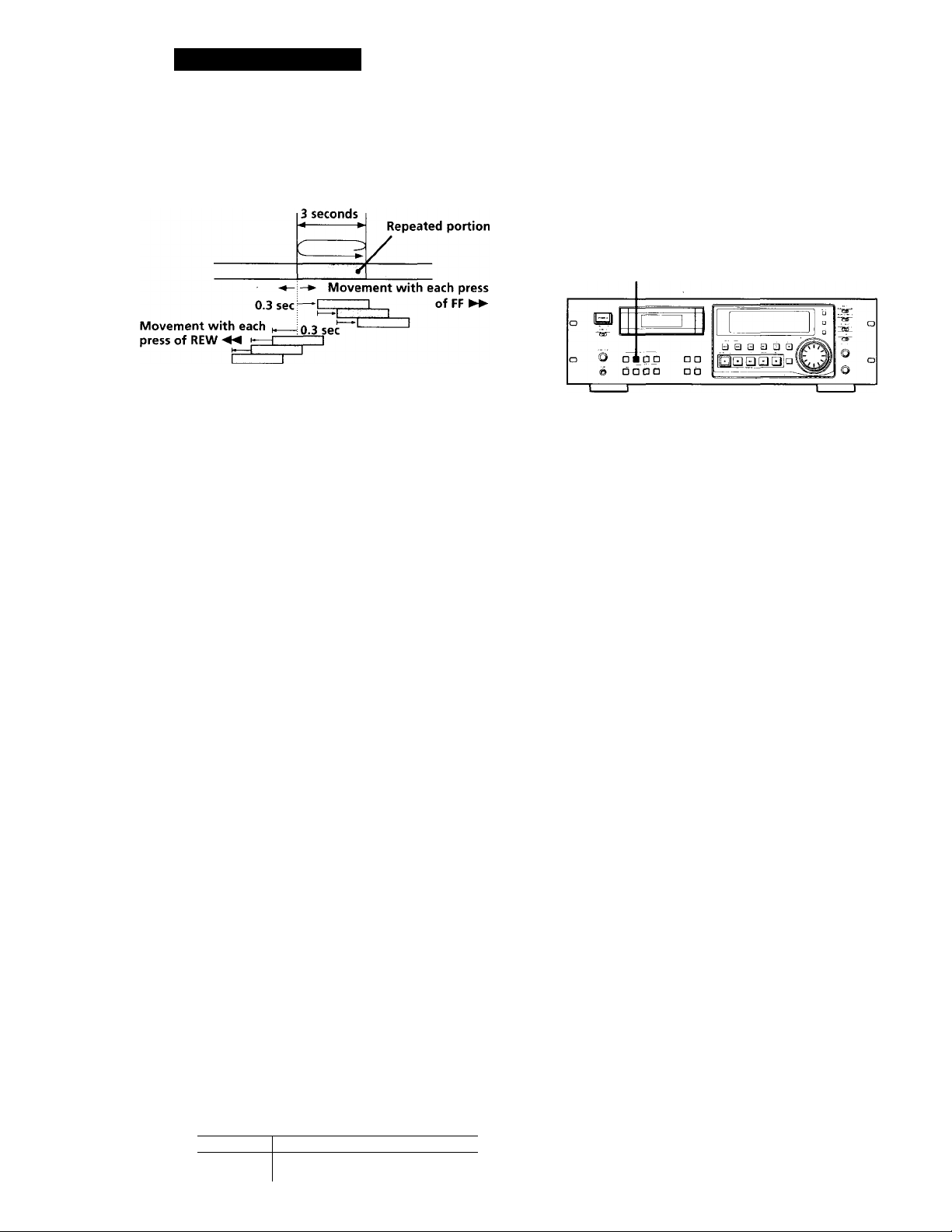
REW -«/FF I
Press REW ◄ ◄ or FF ► ► to move the beginning
of the repeated portion.
Each time you press the REW ◄ ◄ or FF ► ►
button, the beginning of the repeated portion
shifts bacTcwards or forwards in 0.3-second
increments, up to a maximum extent of about 2
seconds (4 seconds in long-play mode) in either
direction.
(Continued)
21'
Page 22
Writing Sub Codes
When writing a start ID
Position where the
REHEARSAL button
is pressed in step 1.
When writing a skip ID
3 seconds
Position where the
REHEARSAL button
is pressed in step 1.
4
Repeated portion
Adjusting the Position of an
Existing Start ID
You can adjust the position of previously recorded
start IDs.
START ID REHEARSAL
During playback, press START ID REHEARSAL
when you arrive at the existing start ID you want
to reposition.
The deck rewinds to the beginning of start ID and
the Rehearsal function repeats a 3-second portion.
Movement with each
press of REW ◄◄
The time in the display shows the shift in position
from the time the REHEARSAL button was
pressed.
Positioning Start ID
After pressing FF ►► twice
After pressing REW ◄◄ twice
Press WRITE of the corresponding ID to write the
ID.
"ID WRITE" appears for a few seconds and the ID
is written on the tape at the selected position.
• Start IDs are 9 seconds long starting from the
beginning of the repeated portion.
• Skip IDs are 1 second long starting from the end
of the repeated portion.
0.3 sec
Movement with each press
__
0.3 sec”
□
X
0.6\w
--0. 6‘ ^
. of FF ►►
Do the steps 2 and 3 of "Accurate positioning of
sub codes" on pages 21 and 22.
You can move the start ID to a maximum extent of
about 2 seconds (4 seconds in long-play mode) in
either direction from its original position.
Notes
• Start IDs written within 10 seconds from the end of the
tape may be difficult or impossible to move.
• Existing skip IDs cannot be moved.
2r
Newly written IDs positioned by the Rehearsal
function
Repeated portion
' Tape direction
y'''/ ,r
Start ID
Skip ID
□ 1
second
'I I 9 seconds
Page 23
Writing Sub Codes
Erasing Sub Codes
You can erase any start ID or skip ID.
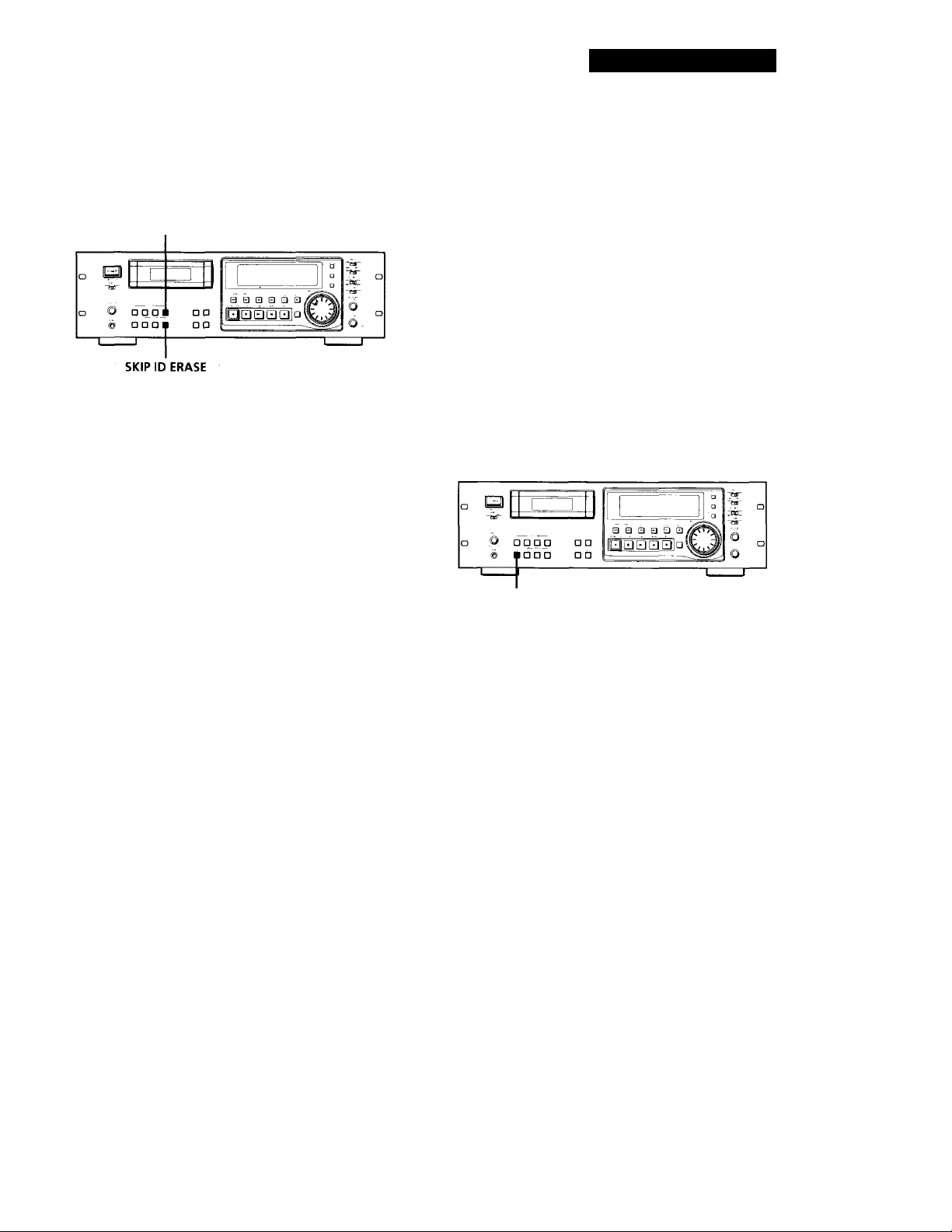
START ID ERASE
Press either START ID ERASE or SKIP ID ERASE when
the ID you want to erase appears in the display.
"(ERASE)" appears in the display as the deck rewinds
to the beginning of the ID, then "ID ERASE" appears as
the deck erases the ID.
In the case of a skip ID, if "SKIP ID" has disappeared
by the time you press SKIP ID ERASE, the deck will
still erase the skip ID.
• It takes 9 seconds to erase a start ID.
• It takes 1 second to erase a skip ID.
• Program numbers are erased together with start IDs.
Renumbering the Program Numbers Automatically (Renumbering Function)
The Renumbering function searches for each start ID
from the beginning of the tape and assigns a new
program number to each one starting with 1. Use the
Renumbering function in the following cases:
• When you've added a start ID while playing the
tape.
• When a program number is missing due to an erased
start ID.
• When you began recording from the middle of the
tape and wrote a program number that already
exists, or when one of the start IDs has no program
number.
RENUMBER
'Q ' You can erase an ID even when it is not displayed
Just press the respective ERASE-button. The tape is
rewound, and the first ID detected is erased.
Note
A skip ID written at the same position of a start ID is erased
when the start ID is erased.
Press RENUMBER while the deck is stopped or
playing.
"RENUMBER" flashes in the display and the tape is
automatically rewound to its beginning. The deck then
starts searching for each successive start ID writing a
new program number for each one starting with 1.
"RENUMBER" stops flashing and "ID WRITE"
appears in the display for a few seconds as the deck
begins rewriting the program numbers.
After renumbering is finished, the deck rewinds the
tape automatically to its beginning, then stops.
Q' You can specify any number as the starting number
for the renumbering of programs.
For details, see "FIRST (PGM No.)" on page 25.
Note
The Renumbering function rhay not function correctly when:
• A blank section exists on the tape.
• The interval between two start IDs is less than 18 seconds
(36 seconds in long-play mode).
• A start ID exists within 10 seconds from the end of the
tape.
23^
Page 24
Menu Operations
Menu Operations
You can make various settings through menu
operations. Settings made through menu are
memorized even when the deck is turned off.
Note
You can do menu operations only when the deck is empty,
stopped or paused.
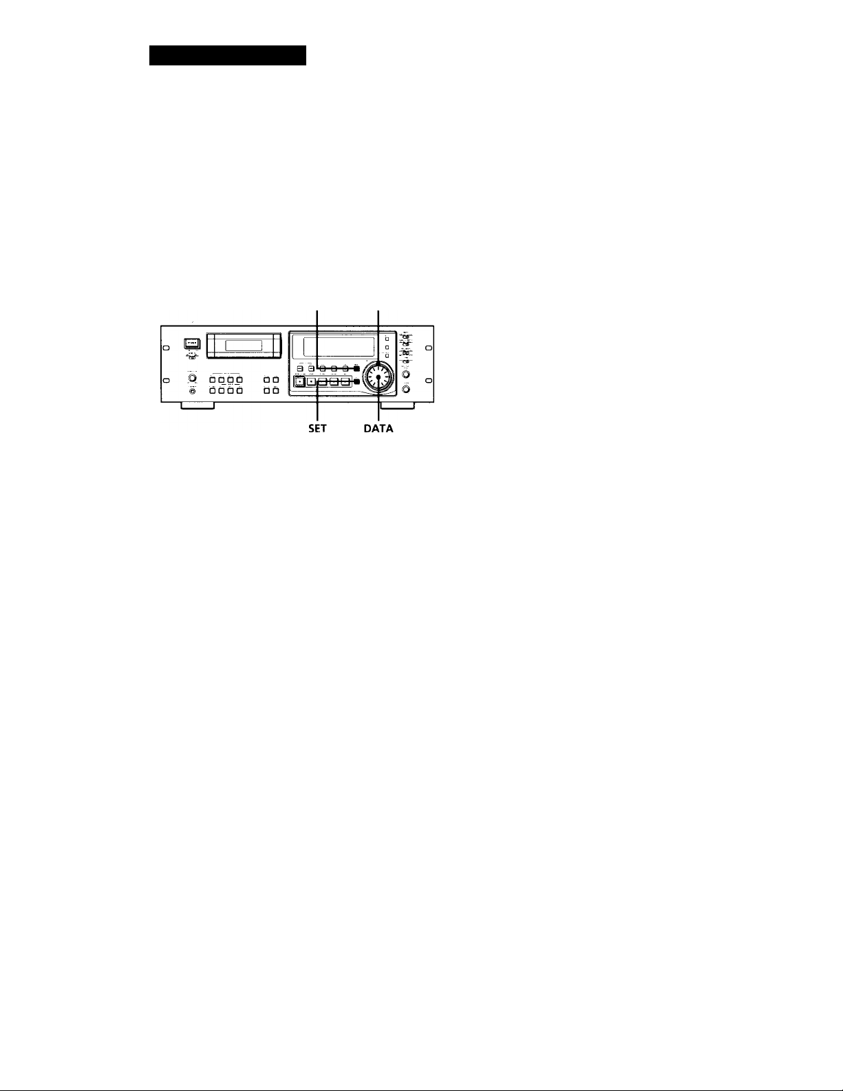
MENU SHUTTLE
Making menu settings
1 Press MENU.
The MENU button lights up.
2 Turn SHUTTLE to select the menu.
3 Turn DATA to select the parameter.
The selected parameter flashes.
REC MUTE (RECord MUTE duration)
Sets the duration if the blank space created between tracks
by the Record Muting function.
Setting range: 0.5 to 9.5 seconds (in units of 0.5 second)
Factory setting: 4 seconds
Reference page: 14
L-SY TH (Level-SYnc THreshold)
Sets the reference inpuf level for automatic writing of starf
IDs.
Setting range: -12 to -60 dB (in units of 1 dB)
Factory setting; -45 dB
Reference page: 20
L-SY BK (Level-SYnc BlanK time)
Sets the length of time that the input signal must remain
below the reference level before automafic writing of start
IDs begin.
Setting range: 1 to 10 seconds (in units of 1 second)
Factory setting: 3 seconds
Reference page: 20
lEC S-ID (lEC Start-ID)
Specifies if start IDs (or skip IDs) are automatically detected
and written on the tape when recording from a DAT deck
connected to the DIGITAL COAXIAL IN connector.
Settings: on (start IDs (or skip IDs) are automatically
detected and written),
— (writing of fhe sfart IDs (or skip IDs) is
determined by the settings of the L-SY TH
and L-SY BK menus)
Factory setting: on
Reference page: 7
24^
When the parameter settings are "on" and (off)
Turn the DATA dial clockwise to select "on" or
counterclockwise to select (off).
4 Press SET.
The selected setting lights up.
5 Press MENU again.
The lit button goes off and the deck becomes
ready for operation.
Menu descriptions
A brief explanation is given below for each menu,
including their settings or setting range, factory setting,
and reference pages.
SET ID6
Selects the copy information to be written on the tape when
recording from the ANALOGfBALANCE/UNBALANCE)
IN connectors or the DIGITAL AES/EBU IN connector.
Settings; 00 (copying permitted), 10 (copying
prohibited), 11 (one generation copy only)
Factory setting: 00
Reference page; 6
lEC CD-Q (lEC CD-Q code)
Specifies if start IDs are written automatically whenever a Q
code defined by fhe user's bits on the CD is detected while
recording from a CD player connected to the DIGITAL
COAXIAL IN connector.
Settings: on (a Q code is detected and written as a
start ID automatically),
-- (writing of the start IDs is determined
by the settings of the L-SY TH and L-SY BK
menus)
Factory setting: on_
Reference page: 7
AES S-ID (AES Start-ID)
Specifies if start IDs (or skip IDs) are automatically
detected and written on the tape when recording from
a DAT deck (for broadcast use) connected to the
DIGITAL AES/EBU IN connector, and if start IDs (or
skip IDs) are output through the DIGITAL AES/EBU
OUT connector.
Settings: on (start IDs (or skip IDs) are detected and
written automatically/start IDs (or skip IDs)
are output),
- (writing of start IDs (or skip IDs) is
determined by the settings of th L-SY TH and
L-SY BK menus/start IDs (or skip IDs) are not
output)
Factory setting; —
Reference page; 7
Page 25
Menu Operations
Automatic writing of start IDs and menu settings during digital recording
The automatic detection and writing of start IDs are carried
out according to the connector to which the program source
is connected, the signal format, and the category code of the
signal, as shown in the table below.
A; Start IDs are detected and written
automatically.
B: Q codes are detected and written as start IDs
automatically.
C: The writing of start IDs is determined by the
settings of the L-SY TH and L-SY BK menus.
Menu settings
Connector
Signal
format
Category
AES/EBU
lEC S-ID on
lEC-S-ID lEC CD-Q on
lEC CD-Q AES S-ID on
AES S-ID - C
—
Broadcast Consumer use
studio use
—
—
—
— — —
— — —
A»»
—
A* A
C C
— — —
— — —
DAT
COAXIAL
CD
—
—
B c
c
others
c
c
c
c
c
* Only when connected to the PCM-2300, PCM-2700, or
PCM-2700A
** Only when connected to the PCM-2600, PCM-2800, PCM-
R500 or PCM-R700.
When the connected decks consist of a PCM-R500 or PCMR700, select "on" in the "AES S-ID" menu of the playback
deck.
DATEDISP (DATE DISPlay)
Specifies if the recording date and time and current date and
time are displayed when the MODE button is pressed.
Settings: on (the recording date and time and current
date and time are displayed), - (the recording
date and time and current date and time are
not displayed)
Factory setting: Reference page: 16
ODER (Date OrDER)
Specifies the display order of the year, month,, and day
indications.
Settings: YMD (year/month/day), DMY (day/month/
•year), MDY (month/day/year)
Factory setting: YMD
Reference page: 8
P-TMDISP (Program TiMe DISPlay)
Specifies if the track playing time is displayed when the
MODE button is pressed.
Settings: on (the track playing time is displayed),
— (the track playing time is not displayed)
Factory setting: on
Reference page: 16
FIRST(P6M No.) (FIRST ProGraM No.)
Specifies the first program number to be assigned to the first
track when recording from the beginning of the tape or
using the Renumbering function.
Setting range: 1 to 99
Factory setting: 1
Reference page: 23
TAPEID6 (ID6 on TAPE)
Displays the copy information of the tape currently inserted.
Indications: 00 (copying permitted), 10 (copying
prohibited), 11 (one generation copy only)
Reference page: 6
CLK-SET (CLOCK SET)
Set to "on" to set the clock.
Reference page: 8
BB-WRT (WRiTe "BB")
Specifies if a lead-in area is created automatically.
Settings: on (a lead-in area is automatically created),
— (a lead-in area is not automatically created)
Factory setting: —
Reference page: 12
BB-FS (FS in lead-in area)
Sets the lead-in area with the frequency of the signals to be
recorded.
Settings: 48kHz, 44kHz, 32kHz
Factory setting: 48kHz
Reference page: 12
HOUR (HOURS meter)
Displays the total drum operating time.
Display range: 0 to 9999 hours (in units of 1 hour)
FADE IN (FADE IN time) (PCM-R700 only)
Specifies the fade-in time for fade-in recording and playback.
Setting range: 0.5 to 9.5 seconds (in units of 0.5 second)
Factory setting: 5.0 seconds
Reference pages: 15 and 19
FADE OUT (FADE OUT time) (PCM-R700 only)
Specifies the fade-out time for fade-out recording and
playback.
Setting range: 0.5 to 9.5 seconds (in units of 0.5 second)
Factory setting: 5.0 seconds
Reference pages: 15 and 19
DATEHOUR(DATE HOUR)
Specifies either a 12-hour or 24-hour format for the time
display.
Settings: 12 (12-hour format), 24 (24-hour format)
Factory setting: 12
Reference page: 8
25^
Page 26
Operations Using the Optional Remote
The Optional Remote RM-D750
You can do the following operations using serial
remote control with an optional remote RM-D750
which may be either connected to the REMOTE 2
connector on the rear panel or not. Eor more
information on other remote operations that are
possible, refer to the Operating Instructions of the
remote.
Note
Set REMOTE on the front panel to WIRED when the remote
is connected to the deck. When using it remotely, set
REMOTE to WIRELESS.
Checking the track order
You can check the order of tracks in your program by
pressing the RMS CHECK button. Each time you press the
RMS CHECK button, the track numbers appear in the order
they were programmed.
Note
You cannot use the CLEAR button to cancel a programmed
track while checking the track order.
To add a track to a program
Repeat steps 1 and 2 while the deck is stopped.
Note
You cannot add a track to a program after RMS Play has
started.
Playing tracks in the order you want (RMS* Play)
RMS Play allows you to specify the playback order of
the tracks on the tape to create your own programs
containing up to 60 tracks (using program numbers 1
to 99). To use RMS Play, however, you must first
record start IDs and program numbers on the tape.
RMS
■ ENTER
■RMS
CHECK
1 Enter the program number (1 to 99) of the track
you want to play.
If you've entered the wrong number
Press CLEAR, then enter the correct number.
2 Press RMS ENTER.
To cancel an entire program
Press ■ repeatedly until "RMS" disappears.
Locating a track by scanning each track
(Music Scan)
You can locate a track by scanning the first 8 seconds of
each track.
CX» CD CD
Q O a CD CD
© © © o o
© © © V© O
©.,_ ©0_Q
S Q Scjcij
C> ■
c±) CD cj ÍIj
,[¡5] c~D ca ^
^ a a
1 Press M.SCAN while the deck is stopped.
2 Press t>.
The deck plays the first 8 seconds of each track in
succession.
■ M.SCAN
26^
ST EP ,l'"iE
Playing Program
order number
j
I
3 Repeat steps 1 and 2.
4 Press O.
The deck starts playing the programmed tracks in
sequence.
RMS = Random Music Sensor
3 When you find the track you want, press
M.SCAN.
The track continues playing.
^ You can use Music Scan while playing a track
If you press the M.SCAN button while playing a track,
the deck will rewind the tape to its beginning, then play
the first 8 seconds of each track on the tape in
succession.
Page 27
Writing and Erasing an End ID
Operations Using the Optional Remote
After repositioning the beginning of the end ID,
press END ID WRITE.
"ID WRITE" appears for a few seconds and the
end ID is written on the tape after a duration of
about 9 seconds after the end of the the repeated
portion.
END ID
REHEARSAL
END ID
WRITE
.END ID
ERASE
II
■ O
'FADER
Writing an end ID during recording
1 When the recording of the program source comes
to an end, press II, O, or FADER.
Recording is paused.
2 Press END ID WRITE.
"ID WRITE" or "EE" appears in the display while
the end ID is being written.
When writing has finished, the record pause
mode is canceled and the deck rewinds the tape to
the beginning of the end ID.
To write an end ID during playback -
Press END ID WRITE.
Erasing the end ID
Press END ID ERASE.
"(ERASE)" appears in the display while the deck fastforwards to the beginning of the end ID, then "ID
ERASE" appears, while the deck erases the end ID. It
takes about 9 seconds (18 seconds in long-play mode)
to erase an end ID.
Q' You can use the End Search function to locate the
end ID
See page 14.
More accurate positioning of the end ID
1 During playback, press END ID REHEARSAL.
"REHRSL" appears in the display, and the
Rehearsal function repeatedly plays back a 3second portion that ends at the point where you .
pressed the button. The repeated portion plays
back 8 times, and the deck stops.
2 Press or ► ► to shift the position of the
beginning of the repeated portion.
Each time you press or ► ► , the beginning of
the repeated portion shifts backwards or forwards
by 0.3-second, up to a maximum extent of about 2
seconds (4 seconds in long-play mode) in either
direction.
The display shows the amount the starting
position has shifted from the time the END ID
REHEARSAL button was pressed.
27^
Page 28
Additional Information
Remote Control Function Using a Parallel Remote Connector
You can operate the deck with a parallel remote control
that uses a switch box connected to the REMOTE 1
connector on the rear panel.
Using the REMOTE 1 connector
When operating the deck with a parallel remote
control, set the REMOTE switch on the front panel to
WIRED.
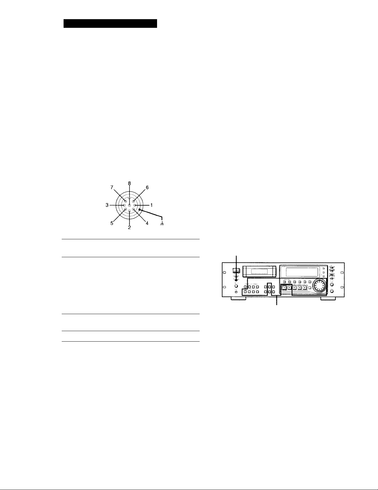
The pin numbers and pin assignments for the
REMOTE 1 connector on the rear panel are as follows:
DIN connector (8 pin)
Notes
• When using MODE 2, use pin number 1 for GND.
• By keeping the input to pin number 1 constant at either Hlevel or L-level determines whether pin numbers 2 to 8 are
in MODE 1 (playback) or MODE 2 (recording).
• In MODE 1, pin number 2 may be used for fader-start
function.
• For pin numbers 2 to 6 pin, input to smaller numbers take
priority.
• Anti-chattering measures should be taken for the
command input switches.
• Status output (pin numbers 7 and 8) is specially provided
for driving a single LED. If more current is needed, use an
additional drive circuit or electric power supply.
• Do not switch input to pin number 1 (MODE 1 and MODE
2) while the deck is playing or recording. This may result
in mis-operation of the deck.
Disabling Button Operations
(Key Protect Function)
Case
Pin No M0DE1
(playback)
Inputs 1
3
4 L-PLAY
5 L-REW
6
Status 7
output
Case
Command inputs H: OPEN (off impedance: 30 kilohms or
Status output H: approx 2V (I=15mA)
8
H-level constant L-level constant
2 ■ H-BTOP/L-PLAY
L-STOP L-START ID
L-FF
H-STOP
H-PLAY
GND
more)
L: GND short (on impedance: 100 ohms
or less)
L: OPEN (High impedance)
M0DE2
(recording)
L-STOP
WRITE
L-PLAY
L-PAUSE
L-REC
H-REC-PAUSE
H-REC
GND
(PCM-R700 Only)
You can disable certain button operations so that the
buttons do not work during, for instance, recording.
KEY PROTECT
AM of these buttons and dials
are disabled.
Set KEY PROTECT to ON.
28^
Connection diagram (MODE 1)
1 2 3 4 5 6 7 8 Case
ci| c!)| (!)| (i| 1)|
OPEN
Command input Status output
switch display (LED)
,GND
Page 29

Additional Information
Precautions
On safety
• Do not disassemble the cabinet as this may result in an
electric shock. Refer servicing to qualified personnel only,
• Should any solid object or liquid fall into the cabinet,
unplug the AC power cord before operating the unit any
further.
On power sources
• Before operating the unit, check that its operating voltage
is identical with your local power supply. The operating
voltage is indicated on the nameplate at the rear of the
unit.
• If you are not going to use the unit for a long time, be sure
to disconnect the AC power cord (mains lead) from the
wall outlet. To disconnect the cord, grasp the plug itself;
never pull the cord.
On operation
If the unit is brought directly from a cold place to a warm
place, or is placed in a very damp room, moisture may
condense on the lenses inside the unit, "CAUTION" may
appear in the display, and the unit may not operate. If this
happens, remove the cassette and leave the unit turned on
for about an hour until the moisture evaporates.
On placement
• Place the unit in a location with adequate ventilation to
prevent heat build-up.
• Do not place the unit:
— on a soft surface such as a rug that might block the
ventilation holes on the bottom.
— near heat sources.
— in direct sunlight.
— in an inclined position.
— in a place subject to excessive dust or mechanical
shock.
On the DAT tapes
• After using a DAT tape, put it into its case and keep it
where it will not be subject to sunlight, high temperature,
moisture or dust.
• The DAT cassette shell is designed to keep out dust. Do
not open the case to expose the tape.
• The hole at the back of the cassette is the detector slot. Do
not cover this slot.
Cleaning
Cleaning the cabinet, panel and controls
Use a soft cloth slightly moistened with a mild detergent
solution. Do not use any type of abrasive pad, scouring
powder or solvent such as alcohol or benzine.
Cleaning the head and tape path
• Prolonged operation will cause contamination of the head.
To obtain the best possible recording and playback sound,
we recommend that you use the Sony DT-IOCL cleaning
cassette (not supplied) to clean the head after every ten
hours or so of operation.
• Clean the head with the cleaning cassette when the deck
has not been used for a long period of time.
Contamination of the head may cause sound drop-out
during playback.
Using the cleaning cassette
1 Insert the cleaning cassette as you would a normal DAT
cassette.
2 Press PLAY ► . After 10 seconds, press STOP ■ .
Do not press the REC 9 or FF ► ► button for cleaning.
3 Remove the cleaning cassette without rewinding it. You
should rewind the cleaning cassette only when it has
reached the end.
Notes on cleaning
• After 10 hours of operation, "CLEANING" appears in the
display for about ten seconds when you turn on the deck.
It is recommended that you clean the head and tape path
periodically, using this message as a guide.
• Due to the shortness of the cleaning cassette, the counter
will not show the actual running time and remaining time
of the cassette.
Regarding tapes of over 120 minutes
Do not use thin-tape cassettes (with a playing time of over
120 minutes) to record important materials since such
cassettes are subject to the following problems:
— Inproper threading of the tape after repeated AMS,
rewinding, fast-forwarding, or cueing operations.
— Incorrect writing and erasing of start IDs.
— Sound distortion.
If you have any questions or problems concerning your
unit, please consult your nearest Sony dealer.
29"
Page 30

Additional Information
Display Messages
The following table explains the various messages that
appear in the display.
Message Meaning
BLANK The deck is searching for the beginning of the
CAUTION
CLEANING
(ERASE)
ID ERASE A start ID or skip ID is being erased.
ID WRITE
M.SCAN
NO TAPE
PROHIBIT
PROTECT
REHRSL Rehearsal function is on.
SOURCE
TAPE END
TAPE TOP
UNLOCK
WAIT
(WRITE) The ID WRITE function is on.
blank section on the tape.
A safety mechanism is operating because of
condensation or other reasons.
Cleaning the head and tape path is
recommended. After about 10 hours of deck
use, this message appears for about 10
seconds whenever you turn on the deck .
The ID ERASE function is on.
A start ID, skip ID, or program number is
being written.
The M.SCAN button on the remote has just
been pressed or Music Scan playback of the
beginning of a track is about to start.
A cassette is not inserted into the deck.
The program source you are about to record
cannot be recorded through the digital input
jacks or connectors.
The record-protect hole on the cassette is open
and recording on the tape cannot be done.
The deck has been-in recording pause for
about 10 minutes, or you've pressed the
REC # button while no cassette is in the deck
or the cassette is record-protected.
The tape has come to the end of the recorded
portion.
The tape has reached its beginning.
The digital signal being input to the jack or
connector is different from the one selected
with the INPUT switch.
The deck is searching for the beginning of the
blank section on the tape.
Troubleshooting
If you've experienced any of the following difficulties
while using the deck, use this section as a guide to
remedy the problem. Should any problem persist,
consult your nearest Sony dealer.
The cassette holder does not close.
^ Check that the cassette is inserted correctly (see
pages 9 and 10).
The function buttons do not work.
^ The deck has just been turned on and will not
operate for about 4 seconds. Wait 4 seconds (10
seconds when "CLEANING" appears) before
attempting any operation.
^ The PAUSE II button is activated. Press
PAUSE II to cancel pause.
^ The tape has reached its end. Press REW
to rewind the tape.
No sound.
^ The deck is not properly connected. Make the
proper connections (see pages 5 and 6).
^ The connected amplifier is not being operated
properly. Operate the amplifier as required for
the respective deck operation. (Refer to the
operating instructions of the amplifier.)
The deck does not record.
The record-protect hole on the cassette is open.
Slide the record-protect tab to close the hole
(see page 11).
^ The INPUT switch is incorrectly set. Set
INPUT, ANALOG INPUT or DIGITAL IN/
OUT to the correct position.
The REG LEVEL CH-1(L)/2(R) controls are set
at 0. Turn them clockwise to raise the
recording level (only during analog recording).
The OPEN/CLOSE ^ button does not work.
^ The OPEN/CLOSE A button does not function
during recording. Press STOP ■ or PAUSE II
to stop recording first, then press
■ OPEN/CLOSE
30^
"CAUTION" appears and the deck cannot be operated.
^ A safety mechanism is operating because of
condensation. Remove the cassette and leave
the deck turned on for about an hour. Then
turn the deck off, then on again (see page 29).
Page 31

Additional Information
Writing or erasing of sub codes is not possible.
^ The record-protect hole on the cassette is open.
Slide the record-protect tab to close the hole
(see page 11).
Start ID writing is not possible during recording.
^ The start ID cannot be written within 18
seconds (36 seconds in long-play mode) after
the end of the previous start ID. Make sure at
least 18 seconds (36 seconds in the long-play
mode) has passed after the last start ftl) and
before writing a new one.
The search function does not stop at the specified track.
^ The specified program number does not exist
on the tape. Press RENUMBER to renumber the
program numbers (see page 23).
The program numbers are out of order. Press
RENUMBER to renumber the program
numbers (see page 23).
The search function operates suddenly during playback.
^ Skip Play is on.
Press SKIP PLAY to turn off "SKIP PLAY" in
the display and cancel Skip Play.
Repeat Play is on.
Press REPEAT repeatedly to turn off
"REPEAT" or "REPEAT 1" in the display and
cancel Repeat Play.
The tape operation buttons do not function while writing
or erasing a start ID, a skip ID or an end ID.
^ All buttons do not work during the 9 seconds
the start ID or end ID is being written or erased
(18 seconds in long-play mode) or during the 1
second the skip ID is being written or erased (2
seconds in long-play mode). Wait until the
writing or erasing the start, skip or end ID
finishes before operation.
The built-in clock does not keep proper time once the
power is turned off.
^ The battery in the deck is weak.
Have the battery replaced by Sony service
personnel (entails a service fee).
After pressing REW ◄◄/FF ►► or PREVIOUS !◄◄/
NEXT ►», the tape stops momentarily before starting
to move.
^ This is normal and is not a mechanical
problem.
The deck cannot be operated with the remote (supplied).
^ The battery is weak. Change both batteries.
^ Set the REMOTE switch to WIRELESS.
The deck cannot be operated with the optional remote
RM-D750.
Set the REMOTE switch according to the
connection between the deck and the remote
(see page 26).
"SBM" does not appear in the display even though SBM
is set to ON.
^ "SBM" appears only during the recording of
analog input signals with a sampling frequency
of 48 kHz or 44.1 kHz, not during the recording
of a digital input signal, or an analog input
signal with a sampling frequency of 32 kHz, or
during playback.
A paticular operation cannot be done as you want.
^ Set the appropriate menu to its default setting.
Absolute time codes writing is not possible.
^ Recording began within a blank section.
Rewind the tape to its beginning, or locate the
end of the recorded portion with End Search
before starting recording.
Tape transport is excessively loud during fast-forwarding
or rewinding.
The noise is caused by the cassette and is not a
mechanical problem.
The tape stops suddenly.
The cassette is defective or damaged.
Press OPEN/CLOSE ^ and replace the cassette
with a new one.
31'
Page 32

Additional Information
Specifications
Recording section
Tape
Recording head Rotary head
Recording time Standard: 120 minutes
Tape speed Standard: 8.15 mm/s
Drum rotation
Error correction
Tape section
Track pitch
Sampling frequency
Modulation system 8-10 modulation
Transfer rate 2.46 Mbit/sec
Number of channels 2 channels, stereo
D / A conversion
(quantization) Long-play: 12-bit non-linear
General section
Power requirements
Where purchased Power requirements
U.S. A./Canada 120 V AC, 60 Hz
Europe/U.K 230 V AC, 50/60 Hz
Power consumption
Dimensions Approx 482 X 145 x 355 mm (w/h/d)
Weight
Remote commander RM-D757 (supplied)
Remote control system Infrared control
Power requirements 3V DC, with two size-AA (R6) batteries
Dimensions
Weight Approx lOOg (3.5 oz) inch batteries
Input connectors
Analog Input
Connector Type Input impedance Rated input level*’
ANALOG Phono(UNBALANCE) plug jack
ANALOG XLR-3
(BALANCE) (FEMALE) or more (factory setting)
Digital audio tape
Long-play: 240 minutes
(DT-120)
Long-play: 4.075 mm/s
Standard; 2,000 rpm
Long-play: 1,000 rpm
Double-encoded Reed Solomon code
13.6 pm (20.4 pm)
48 kHz, 44.1 kHz, 32 kHz
Standard: 16-bit linear
- PCM-R500: 34W
PCM-R700: 34W
(19x5V4 xl4inches)
(not including rack mount adaptor)
PCM-R500: Approx 7.2kg (15 lb 14 oz)
PCM-R700: Approx 7.3kg (16 lb 2 oz)
Approx 45 X 210 X 26 mm (w/h/d)
(I’-Vif-X 8 Vh X 1 Vib inches)
47kilohms -12 dBs
10 kilohms +4 dBs
(balanced)
Digital Input
Connector Type
AES/EBU
XLR-3
(FEMALE)
COAXIAL
Phono-plug
jack
Output connectors
Analog Output
Connector
Type
ANALOG Phono-plug 1 kilohm
Input impedance Rated input level
110 ohms
(balanced)
—
0.5 Vp-p
Output
impedance
Rated
output
level*’
Load
impedance
-12 dBs 47 kilohms
(UNBALANCE) jack
ANALOG
(BALANCE)
PHONES
Digital Output
Connector
AES/EBU
COAXIAL
XLR-3
(MALE)
Stereo phone- .,,
, . c 100 ohms
plug jack
Type
XLR-3
(MALE)
Phono-plug
100 ohms
(balanced)
+4 dBs
(factory
setting)
0.36 mW 32 ohms
Output
impedance
35 ohms
Rated
output
level
—
(balanced)
75 ohms 0.5 Vp-p 75 ohms
10 kilohms
or more
Load
impedance
110 ohms
jack
Variable range of analog (BALANCE) input/output reference level*'
+4 dBs to -12 dBs
Maximum analog (BALANCE) output level
+24 dBs
Remote switch connectors
DIN connector (8-pin, parallel)
Monaural minijack (serial)
Audio characteristics
Frequency response*'
Standard: 20-20,000 Hz (±0.5 dB)
Long-play: 20-14,500 Hz (±0.5 dB)
SIgnal-to-noise ratio*’
90 dB or more (20 kHz LPF, AWeight filter ON)
Total harmonic distortion*’
Standard: 0.05% or less
Long-play: 0.3% or less
(1 kHz, Reference level 20 kHz
LPF ON)
Wow and flutter
Below measurable limit (±0.001%
W.PEAK)
a) The reference level corresponds to -20 dB on the peak
level meters.
b) During analog input with the SBM function off
Supplied accessories See page 4
Design and specifications are subject to change without
notice.
32^
Page 33

Index
About the display 16
Absolute time 16
Current date and time 16
Date and time of recording
16
Playing time of the track 16
Remaining time on the tape
16
Tape running time 16
Absolute time codes 12> 17
Adjusting
the recording level 11
the clock 8
AMS (Automatic music Sensor)
17
Analog connections 5
в
Batteries 4
Blank section 12,14
Cleaning 29
Copy information during
recording 6
Digital connections 5
Digital Interface 6, 7
Digital signal lock range 7
Direct Access 17
Disabling Button Operations
28
Display messages 30
Emphasis 12,16
End ID 19,27
More accute positioning of
the end ID 27
Writing an end ID during
recording 27
Writing and erasing an end
ID 27
End Search 14
Err 16
F, G
Fade-in/Fade-out
Playback 19
Recording 15
Fader 15,'19
н
Hooking up the system 5, 6
Analog connections 5
Digital connections 5
Other connections 6
1, J
Inserting batteries into the
remote 4
К
Key Protect Function 28
Lead-in area 12
M/N
Making menu settings 24
Mark & Locate 17
Menu descriptions 24, 25
Music Scan 26
Optional remote 26, 27
Playing a tape 9
Program numbers 19, 20, 23
Writing program numbers
during recording 20
Specifying the first program
number to be assigned 20
. Q-code 7, 24, 25
Rack mounting 4
Recording on a tape 10,11
Record Monitoring 15
Record Muting 14
Record-protect tab 11
Rehearsal Function 21, 22
Remote control function 28
Renumbering Function 23
Repeat Play 18
Playing a track repeatedly 18
Playing-all tracks repeatedly
18
RMS (Random Music Sensor)
Play 26
S, T, U, V, W. X, Y, Z
SBM function 13
Serial Copy Management
System 6
Setting
the recording mode 13
the clock 8
Shuttle Play 17
Skip Play 18
Skip ID 19,21-24
Writing skip IDs during
recording 21
Sound-muted section 12,14
Start ID 19-25
Adjusting the position of an
existing start ID 22
Writing start IDs during
recording 20
Sub Codes 19-23
Accurate positioning of sub
codes 21, 22
Erasing sub codes 23
Writing sub codes during
playback 21, 22
Names of controls
Buttons
CLEAR 20,26
COUNTER RESET 16
END ID ERASE 27
END ID REHEARSAL 27
END ID WRITE 27
FADER 15,19,27
INPUT MONITOR 15
LOCATE 17
M. SCAN 26,30
MARGIN RESET 11
MARK 17
MENU 8,24
MODE 16,25
PAUSE II 9,11,14,15,19,27,
30
PLAY ► 9,11, 12, 14, 15,17,
26, 29
OPEN/CLOSE± 9_-12,19, 30,
31
. PREVIOUS HM /NEXT 9,
12,17, 31
REC • 11,12,14, 29, 30
RECMUTEO 14,27
RENUMBER 23, 31
REPEAT 18,31
REW ◄ ◄ /EE ► ► 9, 11,12, 14,
15, 21,22, 27, 29-31
RMS CHECK 26
RMS ENTER 26
SET 8, 24
SKIP ID ERASE 23
SKIP ID REHEARSAL 21,22
SKIP ID WRITE 21,22
SKIP PLAY 18,31
START ID AUTO 20
START ID ERASE 23
START ID REHEARSAL 21,22
START ID WRITE 20, 22
STOP ■ ^t, 11, 19, 26, 29, 30
33^
Page 34

Switches
ANALOG INPUT 10,30
DIGITAL IN/OUT 5, 10, 30
INPUT 10,13, 30
KEY PROTECT 9,10, 28
POWER 9,10
REG MODE 7,13
REMOTE 4, 26, 31
SBM 13,31,33
Connectors
ANALOG (BALANCE) IN/
OUT 5, 6,10, 24, 32
ANALOG (UNBALANCE)
IN/OUT 5, 6,10, 24, 32
DIGITAL AES/EBU IN/OUT
5, 6,10, 24, 25, 32
DIGITAL COAXIAL IN/OUT
5, 6,10, 24, 25, 32
REMOTE 1/2 5,6,26,28
Contorols
ANALOG (BALANCE) IN/
OUT LEVEL 5
DATA 8,17,20,24
PHONE LEVEL 9
REG LEVEL CH-1/2 5,11, 30
SHUTTLE 8,17,24
Jacks
PHONES 9, 32
34^
Page 35

AVERTISSEMENT
Bienvenue!
Au sujet de ce mode
Afin d'éviter tout risque
d'incendie ou d'électrocution,
ne pas exposer cet appareil à
la pluie ou à l'humidité.
Afin d'écarter tout risque
d'électrocution, garder le
coffret fermé. Ne confier
l'entretien de l'appareil qu'à
un personnel qualifié.
Pour la clientèle au Canada
ATTENTION
POUR PREVENIR LES CHOCS
ELECTRIQUES, NE PAS UTILISER
CETTE EICHE POLARISEE AVEC UN
PROLONGATEUR, UNE PRISE DE
COURANT OU UNE AUTRE SORTIE
DE COURANT, SAUF SI LES LAMES
PEUVENT ETRE INSEREES A EOND
SANS EN LAISSER AUCUNE PARTIE
A DECOUVERT.
Merci d'avoir acheté cette platine à
cassette audionumérique Sony. Avant la
mise en service de la platine, veuillez
lire attentivement ce mode d'emploi et
le conserver pour toute référence.
Les caractéristiques communes et
particulières à chaque modèle PCMR500 et PCM-R700 sont indiquées
ci-dessous.
Caractéristiques communes
• Moteur 4DD (commande directe)
• Fonction SBM (Super Bit Mapping)
(durant l'enregistrement analogique)
• Support pour trois fréquences
d'échantillonnage (48 kHz, 44,1 kHz
et 32 kHz)
• Installable dans un rack 19 pouces
• Prises d'entrée/sortie XLR
analogiques symétriques
• Interface numérique AES/EBU à
usage professionnel.
• Connecteurs pour télécommande
parallèle et série
• Opérations de menu simples avec les
bagues SHUTTLE et DATA.
• Fonction Mark & Locate
• Commandes REC LEVEL
indépendantes pour les canaux droit
et gauche pour les signaux
analogiques
PCM-R700
• Quatre têtes pour permettre le
contrôle du son enregistré pendant
l'enregistrement
• Fonctions d'enregistrement et lecture
Fade-in/out
• Fonction de protection des touches
Fonctions additionnelles (avec la
télécommande en option)
Lecture RMS, Music Scan, lecture et
effacement d'un identifiant de fin'sont
disponibles. Voir les pages 26 et 27 pour
les détails.
d'emploi
Les instructions de ce mode d'emploi
concernent les modèles PCM-R500 et
PCM-R700. La plupart des illustrations
de ce manuel représentent le modèle
PCMrRSOO excepté dans les cas où il est
indiqué que l'illustration représente le
modèle PCM-R700.
Conventions
• Les commandes indiquées dans les
instructions sont celles sur l'appareil;
elles peuvent cependant être
remplacées par celles de la
télécommande portant des noms
similaires ou, si elles sont différentes,
apparaître dans les instructions entre
parenthèses.
• Les icônes suivantes sont utilisées
dans ce manuel.
Donne des informations et des
^ conseils pour faciliter les
opérations.
Page 36

Table des matières
Préparatifs
Déballage 4
Installation dans un rack 4
Raccordements 5
Interface numérique 6
Réglage de l'horloge 8
Lecture d'une cassette 9 Enregistrement sur une cassette io
Fonctions élaborées pour l'enregistrement
Ce que vous devez savoir avant de commencer à enregistrer 12
Réglage du mode d’enregistrement 13
Utilisation de la fonction SBM (Super Bit Mapping) 13
Localisation de la fin de l'enregistrement précédent (recherche de fin)
14
Création d'un passage en sourdine pendant l'enregistrement (silencieux
d'enregistrement) 14
Contrôle du son enregistré (Contrôle d'enregistrement) 15
Enregistrement avec ouverture/fermeture en fondu (Fader) 15
Fonctions élaborées pour la lecture
A propos de l'affichage 16
Localisation d'une plage (AMS/accès direct) 17
Localisation d'un point (Shuttle Play/Mark&Locate) 17
Répétition de plages (lecture répétée) 18
Lecture des plages avec omission de certains passages (lecture à saut)
- 18
Lecture avec ouverture/fermeture en fondu (Fader) 19
Inscription de sous-codes
Utilisation des sous-codes 19
Inscription d'identifiants de début pendant l'enregistrement 20
Inscription d'identifiants de saut pendant l'enregistrement 21
Inscription de sous-codes pendant la lecture 21
Changement de la position d'un identifiant de début
préenregistré 22
Effacement de sous-codes 23
Renumérotation automatique des numéros de programme 23
Opérations de menu
Opérations de menu 24
Opérations avec la télécommande en option
La télécommande RM-D750 en option 26
Inscription et effacement d'un identifiant de fin 27
Informations supplémentaires
Fonction de la télécommande utilisant un connecteur de télécommande
parallèle 28
Invalidation des opérations aux touches (Fonction Key Protect) 28
Précautions 29
Nettoyage 29
Messages sur l'affichage 30
Guide de dépannage 30
Spécifications 32
Index 33
3^
Page 37

Préparatifs
Déballage
Vérifiez que les accessoires suivants se trouvent dans
l'emballage:
• Cordon d'alimentation secteur (1)
• Télécommande RM-D757 (1)
• Piles de format AA (R6) (2)
• Vis (M5 X 12) (4)
• Rondélles décoratives (4)
• Mode d'emploi (1)
Mise en place des piles dans la
télécommande
Installez deux piles de format AA (R6) en faisant
correspondre les pôles + et - des piles avec le schéma à
l'intérieur du logement.
Installation dans un rack
La platine peut s'installer dans un rack 3U de 19
pouces. N'oubliez pas de déconnecter la platine de la
prise murale avant de l'installer.
1 Retirez les quatre pieds de la platine.
2 Insérez la platine dans le rack et fixez-la avec les
rondelles décoratives et les vis (M5xl2) fournies.
Avant d'utiliser la télécommande
Réglez REMOTE sur le panneau avant à WIRELESS.
REMOTE
WIRED OFF WIRELESS
Quand remplacer les piles
Le piles durent environ six mois dans des conditions
d'utilisation normales. Quand la télécommande ne peut
plus contrôler la platine, remplacez les deux piles par
des neuves.
Remarques
• Ne laissez pas la télécommande dans un endroit
extrêmement chaud ou humide.
• Faites attention que rien ne pénètre dans la télécommande,
en particulier lors du remplacement des piles.
• Ne pas exposer le détecteur infrarouge directement au
soleil ou à un éclairage puissant car un mauvais
fonctionnement pourrait s'ensuivre.
• Si vous ne comptez pas utiliser la télécommande pendant
un certain temps, enlevez les piles pour éviter tout
dommage dû à une fuite d'électrolvte et à la corrosion.
Remarque
Ne réattachez pas les vis’directement après le retrait des
quatre pieds L'emploi de vis plus longues ou plus courtes
pourrait endommager la plaquette de circuits interne.
Rangez les vis et les pieds à un endroit sûr pour pouvoir les"
réutiliser .ultérieurement.
Page 38

Raccordements
Cette section décrit comment raccorder la platine à un
amplificateur, un mixeur stéréo ou d'autres appareils
audionumériques. N'oubliez pas de mettre tous les
appareils hors tension avant d'effectuer les
raccordements.
[H Connecteurs ANALOGIEALANCE) IN/
commandes ANALOG(BALANCE) IN LEVEL
[H Connecteurs ANALOG(BALANCE) OUT/
commandes ANALOG(BALANCE) OUT LEVEL
[U Connecteurs ANALOG(UNBALANCE) IN/OUT
Préparatifs
Connexions analogiques
Pour les connexions via les connecteurs
ANALOG(BALANCE) IN/OUT
Utilisez les câbles XLR symétriques.
Polarité des broches ANALOG(BALANCE) IN/OUT
OUT
1: MASSE
2: CHAUD
3; FROID
1 1
Ajustement du niveau de référence d'entrée/sortie analogique
Le niveau de référence d'entrée/sortie analogique pendant
l'enregistrement ou la lecture est réglé à +4 dBs à l'usine sur
une plage de -20 dB au niveau de bit complet à la fois pour
l'entrée et la sortie.
Pour réduire le niveau de référence, ajustez les commandes
ANALOG(BALANCE) IN/OUT LEVEL sur le panneau
arrière avec un tournevis, à la fois pour CH-1 (L) et CH-2 (R).
Le niveau de référence peut être ajusté sur la plage de +4 à -
12 dBs. Réglez bien les commandes REC LEVEL CH-l(L)/
2(R) du panneau avant en position centrale avant d'effecteur
cet ajustement.
g] Connecteurs DIGITAL AES/EBU IN/OUT
[si Connecteur REMOTE 1 (pour télécommande
parallèle)
rsl Connecteur REMOTE 2 (pour télécommande série)
[U Plot AC IN
U] Connecteurs DIGITAL COAXIAL IN/OUT
[g Commutateur DIGITAL IN/OUT
Pour les raccordements via les connecteurs ANALOG(UNBALANCE) IN/OUT
Utilisez des cordons de raccordement audio à fiche phono.
Raccordements numériques
Utilisez le commutateur DIGITAL IN/OUT sur le
panneau arrière pour sélectionner les connecteurs
d'entrée/sortie pour les signaux numériques. Réglez le
sélecteur à AES/EBU pour sélectionner les connecteurs
DIGITAL AES/EBU IN/OUT, ou à COAXIAL pour
sélectionner les connecteurs DIGITAL COAXIAL IN/
OUT.
Pour les raccordements via les connecteurs DIGITAL AES/
EBU IN/OUT
Utilisez des câbles XLR symétriques, pour les
racconrdements numériques.
Polarité des broches AES/EBU IN/OUT
IN OUT
1: MASSE
2: CHAUD
3: FROID
2 3 113 2
Pour les raccordements via les connecteurs DIGITAL
COAXIAL IN/OUT
Utili.sez des cordons de raccordement numérique coaxiaux.
5^
Page 39

Préparatifs
Autres raccordements
Pour raccorder un bornier via le connecteur REMOTE 1
Voir "Fonction de la télécommande utilisant un connecteur
de télécommande parallèle" à la page 28.
Pour raccorder une télécommande en option via le connecteur REMOTE 2
Voir "La télécommande RM-D750 en option" à la page 26.
Branchement du cordon d'alimentation
Branchez le cordon d'alimentation (fourni) sur la prise
AC IN du panneau arrière et l'autre extrémité sur une
prise murale.
Que faire ensuite?
La platine peut maintenant fonctionner.
Pour les fonctions de base, voir les pages 9 à 11; pour les
fonctions élaborées, voir à partir de la page 12.
Interface numérique
Connecteurs d'entrée et de sortie numérique •
• Le tableau suivant indique les formats de signaux
correspondant aux connecteurs d'entrée et de sortie
de la platine.
• Le connecteur DIGITAL COAXIAL IN accepte non
seulement la version grand public de la norme
d'interface audio numérique internationale IEC-958,
mais aussi la version studio de radiodiffusion de la
norme IEC-958 utilisée pour des platines DAT, telles
que PCM-2300, PCM-2700 ou PCM-2700A.
Information sur la copie pendant l'enregistrement
• L'information sur la copie inscrite sur la bande
pendant l'enregistrement varie selon le connecteur
d'entrée utilisé et le format du signal, comme le
montre le tableau ci-dessous.
• Pour le AES/EBU et le IEC-958 pour les studios de
radiodiffusion, le signal numérique ne contient pas
d'information sur la copie.
• Pour le IEC-958 pour grand public, il existe trois
types d'information sur la copie: copie possible,
copie de première génération autorisée et copie
interdite (Serial Copy Management System).
Connecteur Format du
d'entrée signal
DIGITAL
AES/EBU
DIGITAL
COAXIAL
ANALOG —
(BALANCE/
UNBALANCE)
AES/EBU
IEC-958 pour
studios de
radiodiffusion
IEC-958 pour
grand public
Information
sur la copie
dans le signal sur cette
numérique platine
Néant Oui Déterminée
Néant Oui
Autorisée Oui Autorisée
Première
génération
seulement
Interdite Oui Interdite
—
Possibilité Information
d'enregistrer sur la copie
Oui
Oui
enregistrée
sur la bande
par un réglage
de menu
(pages 24 et 25)
Déterminée
par un réglage
de menu
(pages 24 et 25)
(ID 6:00)
Interdite
(ID 6:10)
(ID 6:10)
Déterminée par
un réglage de
menu (page 24)
6^
Type Connecteur d'entrée
DIGITAL
AES/EBU
DIGITAL
COAXIAL
Format AES/EBU Format AES/EBU
IEC-958 pour le
matériel grand public
IEC-958 pour les studios
de radiodiffusion
Connecteur de sortie
IEC-958 pour grand
public
Page 40

Inscription automatique d'identifiants de début pendant l'enregistrement
• Quand "AUTO" apparaît dans l'affichage pendant
l'enregistrement, l'inscription automatique
d'identifiants de début se fait conformément au
connecteur d'entrée utilisé et au format du signal,
comme le montre le tableau ci-dessous.
• La condition pour l'inscription automatique des
identifiants de début varie selon le code de catégorie
du signal numérique, tel que signal de nive&u
d'entrée audio, identifiant de début DAT, ou code Q
d'une piste CD (voir les pages 24 et 25).
O : inscription automatique possible
X : inscription automatique impossible
Signal
d'entrée
Format du
signal (code
de catégorie)
Inscription automatique conforme
au niveau
d'entrée
audio“'
à l'identifiant au code Q
d’entrée d’une piste
DAT« CD
Préparatifs
DIGITAL
AES/EBU
O
0‘>
X
AES/EBU
IEC-958 pour
O
QJI
X
studios de
radio diffusion
DIGITAL
COAXIAL
ANALOG
IEC-958
pour
erand
public (Autre)
—
O O
O
O
O
X
X X
X
X
O«
X
a) Si le niveau d'entrée reste au-dessous du niveau posé au
menu "L-SY TH" plus que le temps posé au menu "L-SY
BK" (voir la page 24), la platine inscrit un identifiant de
début quand le niveau d'entrée dépasse ce niveau.
b) Des identifiants de saut DAT sont automatiquement
inscrits de la même manière.
c) Seulement quand raccordé au PCM-2600, PCM-2800,
PCM-R500 ou PCM-R700. Quand les platines raccordées
comprennent un PCM-R500 ou PCM-R700, sélectionnez
"on" au menu "AES S-ID" de la platine de lecture,
d) Seulement quand raccordé au PCM-2300, PCM-2700 ou
PCM-2700A.
e) Certains lecteurs CD ne fournissent pas d'information de
page (code Q) dans le signal numérique.
Plage de verrouillage du signal numérique
• La plage de verrouillage du signal numérique (plage
de réception du signal) est d'environ ±0,1% pour une
fréquence d'échantillonnage de 48 kHz, 44,1 kHz ou
32 kHz. Les signaux à hauteur variable ne sont pas
captables.
• Quand l'information de fréquence'd'échantillonnage
d'entrée numérique ne coïncide pas avec la
frécjuence d'échantillonnage actuelle, il est possible
d'enregistrer le signal si le sélecteur REC MODE sur
le panneau avant est réglé à la fréquence
d'échantillonnage actuelle du signal.
T
Page 41

Préparatifs
Réglage de Thorloge
L'horloge intégrée à la platine indique la date et l'heure
courantes. Une fois que la date et l'heure sont réglées
au menu elles sont enregistrées sur la cassette en même
temps que le signal audio pendant l'enregistrement, ce
qui permet de connaître la date d'enregistrement
quand vous regardez la cassette.
MENU SHUTTLE
1 La platine à l'arrêt, appuyer sur MENU.
Le menu s'affiche.
Remarques
• Lorsque vous réglez l'horloge pour la première fois après
le déballage de la platine, " '
vous appuyez sur SET à l'étape 3. C'est normal. Réglez
l'horloge comme expliqué ci-dessus.
• Une pile de réserve alimente l'horloge quand la platine est
hors tension. La pile dure environ sept ans dans des
conditions d'utilisation normales. Quand la pile est
épuisée, l'horloge n'indique plus Theure correctement. A
ce moment, faites remplacer la pile (service payant) par un
revendeur ou dans un centre de service après-vente Sony.
---------- " apparaît quand
2 Tournez SHUTTLE pour afficher le menu "CLK-
SET".
3 Tournez DATA pour afficher "on", puis appuyez
sur SET.
L'indication de Tannée clignote.
4 Tournez DATA pour augmenter ou diminuer
Tannée affichée, puis appuyez sur SET.
L'indication de Tannée s'arrête de clignoter et
l'indication du mois se met à clignoter à son tour.
’96'it bel 9 Sfi
5 Répétez l'étape 4 jusqu'à ce que tous les autres
paramètres soient réglés. Apres le réglage des
secondes, appuyez sur SET pour mettre l'horloge
en marche.
Le jour de la semaine est automatiquement réglé et affiché comme suit;
Dimanche: "SU", lundi; "MO", mardi: "TU", mercredi:
"WE", jeudi: "TH", vendredi: "FR" et samedi: "SA".
8^
Pour afficher la date ou Theure
Voir "A propos de Taffichage" à la page 16.
'Ç* Vous pouvez spécifier le format (12 heures ou 24
heures) pour Taffichage de Theure, et Tordre
d'affichage pour la date.
Pour les détails, voir "ODER" ou "DATEHOUR" à la
page 25,
Ç* Pour que Theure soit enregistrée avec précision
Remettez l'horloge n l'heure une fois p.ir semaine.
Page 42

Opérations de base
Lecture d'une cassette
2
Voir les pages 5 et 6 pour les raccordements.
Ç" Pour utiliser des écouteurs
Raccordez-les au connecteur
PHONES. Réglez le v'olume avec
la commande PHONE LEVEL.
Mettez l'amplificateur sous tension et réglez le sélecteur de
1
source à la position DAT.
Appuyez sur POWER.
Vérifiez que le commutateur KEY PROTECT est réglé à OEF
(PCM-R700 seulementKvoir la page 28).
Appuyez sur OPEN/CLOSE ^ et insérez une cassette.
Côté avec fenêtre
OPEN/CLOSE
A Appuyez sur PLAY. ► .
vers le haut
Insérez la cassette
jusqu'au déclic.
OPEN.'CLOSE
Appuyez sur OPEN/
CLOSE ± pour refermer
le logement de cassette.
La lecture commence sur la platine. Réglez le volume sur
l'amplificateur.
‘WP»
Pour Appuyez sur
Arrêter la lecture STOPH
Faire une pause de lecture
Passer à la plage suivante ou
précédente
Avancer rapidement ou
rebobiner ta bande
Avancer rapidement ou rebobiner
la bande en contrôlant le son
Enlever la cassette.
PAUSE II. Appuyez à nouveau sur la touche ou
sur PLAY ► pour reprendre la lecture.
NEXT ou PREVIOUS F«
FF ► ► ou REW ◄ ◄ quand la platine est à l'arrêt
FF ► ► ou REW pendant la lecture. Relâchez
la touche pour reprendre la lecture normale.
OPEN/CLOSE ^ après l’arrêt de la lecture
9'
Page 43

Opérations de base
Enregistrement sur une
cassette
Voir les pages 5 et 6 pour les
raccordements.
Mettez l'amplificateur sous tension et démarrez la lecture du
1
programme que vous souhaitez enregistrer.
Appuyez sur POWER.
Vérifiez que le sélecteur KEY PROTECT est réglé à OEE (PCMR700 seulement)(voir la page 28).
Appuyez sur OPEN/CLOSE ^ et insérez une cassette.
Côté avec fenêtre
vers le haut
OPEN/CLOSE
jusqu'au déclic.
A Utilisez INPUT, ANALOG INPUT et DIGITAL IN/OUT pour
OPEN/CLOSE
Appuyez sur OPEN/CLOSE
± pour refermer le
logement de cassette.
sélectionner les connecteurs d'entrée correspondants.
10"
Pour enregistrer via
ANALOG
(BALANCE) IN
ANALtX:
(UNBALANCE) IN
DIGITAL AES/EBU
IN
DIGITAL COAXIAL INDIGITAL
* Le commutciteur DIGITAL IN/OUT est situé sur le pannenu arrière (voir ta page 5).
INPUT
ANALOG BALANCE
ANALOG
DIGITAL
Position des sélecteurs
ANALOG INPUT
UNBALANCE
—
—
DIGITAL IN/OUT*
AES/EBU
COAXIAL
—
—
Page 44

Si "UNLOCK" apparaît dans
l'affichage
L'appareil de source de
programme n'est pas connecté
correctement à la platine ou
n'est pas sous tension.
Assurez-vous qu'il est
connecté correctement ou
sous tension.
Pour ajuster plus
V'
précisément le niveau
d'enregistrement
En contrôlant le son, tournez
REC LEVEL CH-1(L)/CH2(R) de sorte que le niveau
d'enregistrement des
indicateurs de pointes soit au
niveau maximum sans entrer
sur la plage OVER.
Opérations de base
Localisez l'endroit où vous souhaitez commencer
l'enregistrement.
Pour enregistrer depuis le début de la bande
Appuyez sur REW « pour rebobiner la bande jusqu'à son
début.
Pour commencer à enregistrer à la fin de l’enregistrement précédent
1 Appuyez sur REW ◄ ◄ pour rebobiner la bande jusqu' à son
début.
2 Appuyez sur FF I
La platine localise la fin de l'enregistrement précédent et
s'arrête automatiquement.
Appuyez sur REC •.
La platine est prête pour l'enregistrement.
L'enregistrement ne commence pas encore.
Pour l'enregistrement d'un signal d'entrée analogique, réglez le
niveau d'enregistrement avec REC LEVEL CH-1(L)/CH-2(R).
Le niveau d'enregistrement recommandé est le point central.
30 20 12
Niveau maximum ■
Reste éteint
Les segments des indicateurs
de pointes correspondant à la
puissance maximal du signal
restent allumé plus
longtemps qu'à l'ordinaire.
L'indication MARGIN,
changeant à chaque signal
plus puissant, indique la
marge entre la puissance du
signal et 0 dB.
Si le niveau dépasse 0 dB
Les segments sous "OVER"
s'allument, et "O.OdB"
clignote dans l'affichage. Si
ces segments restent allumés,
il peut y avoir des
déformations sonores.
Pour éviter cela, maintenir le
niveau d'enregistrement entre
-12dBet0dB.
Pour remettre l'indication
de marge à zéro
Appuyez sur MARGIN
RESET. L'indication de marge
passe à - dB".
Appuyez sur PAUSE II ou PLAY I
8
L'enregistrement commence.
Démarrez l'enregistrement de la source de programme.
Quand la bande arrive à sa fin, la platine la rebobine
automatiquement jusqu'à son début et s'arrête (rebobinage
automatique).
Pour
Arrêter l'enregistrement
Faire une pause d'enregistrement
Retirer la cassette
Pour éviter tout effacement accidentel
Glissez le taquet de protection contre l'enregistrement vers la gauche comme
indiqué sur l'illustration.
Appuyez sur
STOPH
PAUSE II. Appuyez une seconde fois sur la
touche ou appuyez sur PLAY ► pour
reprendre l'enregistrement.
OPEN/CLOSE A après avoir arrêté
l'enregistrement.
Enregistrement
impossible (
n impossible (l'orifice
est ouvert)
Enregistrement
possible (l'orifice
est fermé)
ir
Page 45

Fonctions élaborées pour l'enregistrement
Ce que vous devez savoir avant de commencer à enregistrer
Différence entre un passage vierge et un passage en sourdine
La platine différencie les deux types de passage
silencieux, appelés "passage vierge" et "passage en
sourdine".
Pour enregistrer les codes de temps absolu avec précision
• Si la cassette est vierge, commencez l'enregistrement au
début de la bande.
• Utilisez le silencieux d'enregistrement (voir page 14) pour
insérer des espaces entre les plages. Ne pas avancer la
bande avec les touches PLAY ► et FF
• Si vous voulez commencer à enregistrer au milieu de la
cassette, utilisez la fonction de recherche de fin (voir page
14) pour localiser la fin de l'enregistrement précédent afin
d'éviter de laisser un passage vierge.
Passage vrerge
C'est un passage sur lequel aucun signal n'a été enregistré.
Passage en sourdine
C'est un passage sur lequel un signal a été enregistré mais à
un niveau tellement faible qu'il n'est pas audible.
E)
T/'yy////,
y P) #
m
-'y//y////
Passage en sourdine E): Enregistrement
Important
Veillez à ne pas laisser de passage vierge pendant
l'enregistrement. La présence de passages vierges
au milieu d'un enregistrement rend impossibles les
opérations de recherche avec les touches
PREVIOUS «◄/NEXT et brise la continuité des
codes de temps absolu.
is
Si
P): Plage
Zone d'amorçage
Si vous insérez une nouvelle cassette, la platine détecte
l'amorce de la bande et crée automatiquement une
zone d'amorçage conformément au réglage du menu,
comme indiqué dans la figure ci-dessous. A ce
moment-là, "BB" apparaît dans l'affichage environ 1
seconde. La zone d'amorçage risque d'être effacée par
inadvertance sur une autre platine DAT si vous
appuyez sur REC # pour lancer l'enregistrement au
début de la bande sans avoir fermé le logement de la
cassette. Pour éviter cela, appuyez sur OPEN/CLOSE
^ pour refermer le logement de cassette avant de
commencer l'enregistrement.
Voir "BB-WRT" et "BB-FS" à la page 25 pour les détails
sur la sélection de la création automatique de la zone
d'amorçage et de la fréquence des signaux à
enregistrer.
"BB" apparaît sous PGM NO.
Amorce de la bande Zone d'amorçage
Point de départ de
enregistrement
Si "EMPHASIS" apparaît sur l'affichage
La platine est en train d'enregistrer un signal
numérique avec accentuation (dans les fréquences
supérieures). L'enregistrement contiendra également la.
même accentuation.
12^
Codes de temps absolu
Les codes de temps absolu indiquent le temps écoulé
depuis le début de la cassette. Une fois que les codes de
temps absolu sont enregistrés, ils ne peuvent pas être
réinscrits.
Si vous laissez la platine en pause
d'enregistrement pendant plus de 10
minutes
La pause d'enregistrement est automatiquement
annulée et la platine entre en mode d'arrêt pour la
protection de la bande. "SOURCE" apparaît sur
l'affichage du PCM-R300.
Pour poursuivre l'enregistrement, appuyez sur la
touche REC #. La platine entre en pause
d'enregistrement.
Page 46

Réglage du mode d'enregistrement
Fonctions élaborées pour l'enregistrement
Le temps d'enregistrement en mode longue durée
(sélecteur REC MODE sur LONG) est deux fois plus
long qu'en mode standard.
Vous avez le choix entre deux modes d'enregistrement,
standard ou longue durée, dans les cas suivants.
• Quand vous enregistrez un signal analogique avec le
sélecteur INPUT réglé sur ANALOG.
• Quand vous enregistrez un signal numérique d'une
fréquence d'échantillonnage de 32 kHz aveq le
sélecteur INPUT réglé sur DIGITAL.
REC MODE
Réglez le sélecteur REC MODE pour choisir le mode
d'enregistrement.
Le tableau suivant indique les choix possibles, la
position correspondante du sélecteur REC MODE et la
fréquence d'échantillonnage des divers signaux
d'entrée.
Signal d'entrée
Position du
sélecteur REC
MODE
Mode
d'enregistrement
Ç' Compteur en mode longue durée
Le temps de défilement, le temps absolu et le temps
restant affichés représentent les valeurs du mode
standard. Multipliez les valeurs par deux pour obtenir
les temps correspondants en mode longue durée.
Remarque
Ne changez pas la position des sélecteurs INPUT et REC
MODE au cours de l’enregistrement car l'affichage "PGM
TIME" ne serait plus correct.
Utilisation de la fonction SBM
(Super Bit Mapping)
La fonction SBM utilise le principe de l'ouïe humaine et
la technologie de modelage du bruit pour réduire le
bruit de quantification sur la bande de fréquences.
Vous pouvez utiliser la fonction SBM pour enregistrer
un signal analogique uniquement quand le sélecteur
INPUT est réglé sur ANALOG et le sélecteur REC
MODE sur STANDARD (48 kHz ou 44,1 kHz).
Analogique STANDARD
Numérique
(32kHz)
Numérique
(44.1kHz)
Numérique
(48kHz)
(48k)
STANDARD
C44,lk)
LONG Longue durée
STANDARD
(48k)
STANDARD
(44,1k)
LONG
STANDARD
(48k)
STANDARD
(44,1k)
LONG Standard (44,1kHz)
STANDARD
(48k)
STANDARD
(44,1k)
LONG
Standard (48kHz)
Standard (44,1kHz)
(32kHz)
Standard (32kHz)
Standard (32kHz)
Longue durée
(32kHz)
Standard (44,1kHz)
Standard (44,1kHz)
Standard (48kHz)
Standard (48kHz)
Standard (48kHz)
Réglez SBM sur ON.
"SBM" apparaît sur l'affichage pendant
l'enregistrement avec la fonction SBM.
Remarque
La fonction SBM agit uniquement pendant l'enregistrement.
Cependant, vous pouvez profiter du son amélioré par la
fonction SBM pendant la lecture, quel que soit la position de
l'interrupteur SBM ou la platine DAT utilisée.
13"
Page 47

Fonctions élaborées pour l'enregistrement
Localisation de la fin de
l'enregistrement précédent
(recherche de fin)
Quand vous commencez à enregistrer au milieu d'une
cassette, utilisez cette fonction pour localiser la fin de
l'enregistrement précédent afin de ne pas laisser
d'espace vierge sur la cassette.
FF^»-
Appuyez sur FF ► ► quand la platine est à l'arrêt.
La platine localise la fin de la partie enregistrée (le
début du passage vierge ou la position de l'identifiant
de fin), puis s'arrête.
La platine localise la fin de l'enregistrement précédent
(et le début du passage vierge), puis s'arrête. La platine
s'arrête au début de tout passage vierge qui dure 9
secondes ou plus et elle avance la bande jusqu'à la fin
si la cassette est vierge.
Si vous appuyez sur la touche REC • lors d'un passage vierge
La platine rebobine la bande jusqu'au début du passage
vierge et entre en pause d'enregistrement. "BLANK" et
"WAIT" apparaissent sur l'affichage pendant que la
platine recherche le début du passage vierge.
Remarque
La recherche de fin n'a pas lieu si vous appuyez sur la
touche FF ► ► au cours d'un passage vierge.
Création d'un passage en
sourdine pendant
l'enregistrement (silencieux
d'enregistrement)
Utilisez le silencieux d'enregistrement pour insérer un
espace d'environ 0,5 à 9,5 secondes entre les plages
pendant l'enregistrement ou en pause
d'enregistrement.
Pour les détails sur le réglage de la durée de l'espace
vierge, voir "REC MUTE" à la page 24.
Appuyez sur REC MUTE O à l'emplacement où vous
souhaitez insérer un espace alors que la platine est en
cours d'enregistrement ou en pause d'enregistrement.
"REC" se met à clignoter dans l'affichage et la bande
continue à défiler, mais aucun signal n'est enregistré.
Après l'insertion d'un espace. Il reste allumé dans
l'affichage et la platine passe en pause
d'enregistrement.
Pour insérer un espace vierge (d'une durée différente de
celle préréglée au menu)
Maintenez la touche REC MUTE O enfoncée aussi
longtemps que nécessaire. Quand vous relâchez la touche
REC MUTE O,
d'enregistrement. Après le passage de la durée préréglée,
"REC" se met à clignoter plus rapidement et l'indicateur
MARGIN affiche le temps de pression de la touche REC
MUTE O.
Il reste allumé et la platine passe en pause
14"
Pour insérer un espace vierge d'une durée plus courte
que la valeur préréglée
Appuyez sur REC 9 alors que "REC" clignote. La platine
recommence à enregistrer.
Remarque
Si vous ne créez pas de passage en sourdine au début de la
bande, il sera difficile de déplacer ou d'effacer tout
identifiant de début (voir la page 19) enregistré moins de 2
secondes après le début de la bande.
Page 48

Fonctions élaborées pour l'enregistrement
Contrôle du son enregistré
(Contrôle d'enregistrement)
(PCM-R700 seulement)
Vous pouvez comparer le son enregistré avec le son de
la source pendant l'enregistrement.
Pendant l'enregistrement, appuyez sur INPUT
MONITOR pour éteindre "INPUT" sur l'affichage.
Le son enregistré est fourni.
L=jJl
S'éteint.
Enregistrement avec
ouverture/fermeture en fondu
(Fader) (PCM-R700 seulement)
Vous pouvez utiliser l'atténuateur pour une ouverture
en fondu au début de l'enregistrement ou une
fermeture en fondu en fin d'enregistrement. C'est
pratique quand vous souhaitez démarrer ou arrêter un
enregistrement au milieu d'un morceau.
Les durées d'ouverture/fermeture en fondu peuvent
être spécifiées entre 0,5 et 9,5 secondes par des réglages
de menu.
Pour les détails, voir "FADE IN" et "FADE OUT" à la
page 25.
FADER
Pour écouter la source de programme
Appuyez sur INPUT MONITOR pour allumer "INPUT" sur
l'affichage.
Ç" Vous pouvez écouter la source de programme même
quand elle n'est pas enregistrée
Appuyez sur INPUT MONITOR pour allumer "INPUT"
sur l'affichage.
La source de programme est fournie quand.
• la platine est arrêtée.
• la cassette est éjectée.
La source de programme n'est pas fournie quand
"INPUT" est éteint.
Remarque
Si vous effectuez une des opérations suivantes tout en
écoutant la source de programme, "INPUT" s'éteint, la
source de programme n'est plus fournie et "INPUT" ne
s'allume pas même si vous appuyez sur la touche INPUT
MONITOR:
• Vous démarrez la lecture en appuyant sur la touche
PLAY ► .
• Vous interrompez la lecture en appuyant sur la touche
PAUSE II.
• Vous appuyeV sur la touche REW
• Vous appuyez sur la touche FF
Ouverture en fondu
Appuyez sur FADER alors que la platine est en mode
de pause d'enregistrement.
"FADE IN" s'affiche et l'affichage de temps compte à
rebours jusqu'à "0.0s" pendant l'ouverture en fondu.
Fermeture en fondu
Appuyez sur FADER pendant que l'appareil
enregistre."FADE OUT" s'affiche et l'affichage de
temps compte à rebours jusqu'à "0.0s" pendant la
fermeture en fondu. Après la fermeture en fondu, la
platine passe automatiquement en mode de pause
d'enregistrement.
Remarque
Cette platine est pourvue d'un fader permettant l'ouverture
ou fermeture en fondu en 256 étapes. Du bruit de
commutation peut cependant apparaître pendant
l'enregistrement de signaux de niveau faible ou d'une
tonalité d'essai. Dans ce cas, utiliser le fader d'un
composant, tel que mixeur, raccordé à l'appareil.
15^
Page 49

Fonctions élaborées pour la lecture
A propos de l'affichage
Vous pouvez utiliser l'affichage pour indiquer le temps
de défilement de la bande, le temps absolu, le temps de
lecture d'une plage, le temps restant sur la bande, la
date et l'heure d'enregistrement et la date et l'heure
courantes.
Le temps de lecture de la plage ne sera pas affiché quand
l'item de menu "P-TMDISP" est réglé à (voir la page
25).
La date et l'heure de l'enregistrement et la date et l'heure
courantes ne seront pas affichées sur l'item de menu
"DATEDISP" est réglé à " (voir la page 25).
Mais rien n'apparaîtra si ces informations ne sont pas
inscrites sur la bande.
COUNTER RESET MODE
Appuyez de manière répétée sur MODE.
A chaque pression, l'information affichée change
comme suit.
Temps absolu
Appuyez {y
Temps de lecture
de la plage
Appuyez {y
Temps de
lecture restant
8™20.
3.15.
KOO.
Dans le cas des cassettes préenregistrées, le temps restant
signifie le temps jusqu'à la fin de l'enregistrement.
Appuyez {y
Date courante
et jour de la
semaine**
Heure
courante**
Date et jour de la
semaine de
Tenregistrementîî,
Temps
d'enregistrement
total**
***
Temps de
défilement de la
bande
’96 10-19 SPI
Appuyez
1 „30.00. PIM
Appuyez -(y
’94 1 FR
Appuyez -{Jr
I0„13.26. PM
Appuyez {y
5. 19.
Appuyez
Pour remettre le temps de défilement de la bande à zéro
Appuyez sur COUNTER RESET.
Quand "DATE" est affiché
"DATE" reste allumé quand la date et le jour de la semaine
ou la date de l'enregistrement apparaissent, et clignote
quand la date et l'heure courantes apparaissent.
Remarques
• Lors de la lecture de certaines cassettes préenregistrées,
"BB" peut apparaître momentanément sur l'affichage au
début de la cassette.
• Le temps de lecture de la plage n'est pas affiché dans les
cas suivants:
— Quand la lecture commence au milieu de la plage.
— Pendant le rebobinage.
• En mode de lecture standard, le temps de lecture restant
apparaît au bout de 16 secondes environ après le
commencement de la lecture.
• Le temps de lecture restant affiché diffère parfois
légèrement du temps restant réel en fonction des cassettes
utilisées.
Si "EMPHASIS" apparaît sur l'affichage
La platine est en train de reproduire un signal audio
enregistré avec accentuation (dans les fréquences
supérieures). La platine reproduit le signal tout en le
désaccentuant automatiquement (l'atténuation est
proportionnelle au degré d'accentuation).
"ERR" apparaît dans l'affichage 5 secondes ou plus
• La tête est sale.
Nettoyez la tête avec une cassette de nettoyage DAT
(voir la page 29.)
• La cassette est défectueuse ou endommagée.
16"
Page 50

Fonctions élaborées pour la lecture
Localisation d'une plage (AMS*/ accès direct)
Vous pouvez localiser les plages de diverses manières
mais auparavant vous devez enregistrer des codes ID de
départ sur la bande (voir les pages 19 à 23). Pour l'accès
direct, vous devez d'abord enregistrer des numéros de
programme sur la bande (voir les pages 19 et 23).
PREVIOUS I
Appuyez sur Appuyez sur
Le début des plages
suivantes (AMS)
Le début de la plage
courante (AMS)
Le début des plages
précédentes (AMS)
En désignant le numéro
de programme de la plage
(accès direct)
* AMS = Automatic Music Sensor
Ç Si vous avez entré un numéro de programme
incorrect lors de l'accès direct
Si vous n'avez pas appuyé sur la touche PLAY^,
tournez la bague DATA sur la platine (ou appuyez sur
la touche CLEAR, puis entrez le numéro correct à la
télécommande).
*Ç* Si la platine détecte un passage vierge de 9
secondes'ou plus, un identifiant de fin, ou la fin de
la bande
La platine rebobine automatiquement la bande jusqu'à
son début et s'arrête (rebobinage automatique).
'Ç* Vous pouvez démarrer automatiquement la lecture
depuis le début de la bande après le rebobinage
(lecture automatique)
Appuvez sur la touche PLAà ► en maintenant la
touche RHW entoncee.
l/NEXTI PLAY I
NEXT autant que fois que
nécessaire pendant la lecture.
Par exemple, appuyez deux fois
pour localiser la deuxième plage
suivante.
PREVIOUS une fois
pendant la lecture.
PREVIOUS autant que fois
que nécessaire pendant la lecture.
Par exemple, appuyez trois fois
pour localisér l'avant-dernière
plage.
Quand la platine est en cours
de lecture ou à l'arrêt, tournez
DATA sur le panneau av^ant
jusqu'à ce que le numéro de
programme souhaité
apparaisse (ou entrez le
numéro de programme aux
touches numériques de la
télécommande).
Appuyez sur PLAY ► .
(Détecteur automatique de musique)
Localisation d'un point
(Shuttle Play/Mark & Locate)
Vous pouvez localiser un point spécifique en lisant à
une vitesse différente ou en enregistrant le code de
temps absolu au point à localiser ultérieurement.
Pour localiser
Une plage en utilisant la
lecture à vitesse variable
(Shuttle Play)
Un point particulier sur la
bande (Mark & Locate)
Ç Vitesse de lecture en Shuttle Play
Pendant la lecture en Shuttle Play, il est possible de
faire varier la vitesse de lecture de ±0,5 à ±8 fois la
vitesse de lecture normale (ou ±1 à ±8 fois la vitesse
normale pour les matériaux enregistrés en mode de
lecture longue), selon l'angle et la directiirn de la bague
SHUTTLE. Tournez la bague dans le sens horaire pour
la lecture en avant ou dans le sens anti-horaire pour la
lecture en arrière.
La vitesse.de lecture sera de ±8 fois la vitesse normale
quand la bague sera tournée à fond vers la droite ou la
gauche.
Remarque
Shuttle Play soit être utilisé seulement en cas de
nécessité; un usage prolongé risquerait d'endommager
la bande et te tambour..
'Ç* * Le point mémorisé avec la fonction Mark & Locate
sera effacé:
— au retrait de la cassette.
— à la mise hors tension de l'appareil.
Procédez comme suit
Pendant la lecture, l'arrêt ou la
pause de la platine, tournez
SHUTTLE:
• Si la platine était en train de lire
ou à l'arrêt, la lecture commence
à la libération de la bague
SHUTTLE.
• Si la platine était en pause, la
platine reste en mode pause cà la
libération de la bague
SHUTTLE.
Appuyez sur MARK alors que
la platine est en train de lire ou
à l'arrêt. Le temps absolu du
point où la touche a été
pressée apparaît et clignote
trois fois.
Appuyez sur LCX2ATE. La
platine localise le point et
s'arrête.
17^
Page 51

Fonctions élaborées pour la lecture
Répétition de plages (lecture répétée)
Vous pouvez répéter la lecture d'une plage ou de
toutes les plages.
REPEAT
Répétition de toutes les plages
Appuyez plusieurs fois sur REPEAT pendant la lecture
d'une plage jusqu'à ce que "REPEAT" apparaisse sur
l'affichage.
La platine reproduit toutes les plages 5 fois, puis
s'arrête. Si la platine détecte une des conditions
suivantes pendant la lecture répétée, elle rebobine la
bande jusqu'au début et recommence la lecture.
— Un passage vierge de 9 secondes ou plus.
— La fin de la bande.
Lecture des plages avec omission de certains passages (lecture à saut)
Vous devez d'abord inscrire des codes ID de saut (voir
la page 19) avant de pouvoir utiliser la lecture à saut.
Appuyez sur SKIP PLAY.
"SKIP PLAY" apparaît sur l'affichage. Quand la platine
détecte un code ID de saut, elle avance la bande
rapidement jusqu'au code ID de départ suivant, puis la
lecture se poursuit.
Pour annuler la lecture à saut
Appuyez sur SKIP PLAY.
"SKIP PLAY" disparaît de l'affichage.
Pour annuler la répétition de toutes les plages
Appuyez plusieurs fois sur REPEAT jusqu'à ce que
"REPEAT" disparaisse de l'affichage.
Remarque
La répétition de toutes les plages est également annulée si
vous éjectez la cassette.
Répétition d'une plage
Appuyez plusieurs fois sur REPEAT pendant la lecture
de la plage à répéter jusqu'à ce que "REPEAT 1"
apparaisse sur l'affichage.
La platine reproduit la plage 5 fois, puis s'arrête.
Si la platine détecte une des conditions suivantes
pendant la lecture répétée, elle rebobine la bande
jusqu'au code ID de départ de la plage courante et
recommence la lecture à partir de ce point.
— Le code ID de départ suivant.
— Un passage vierge de 9 secondes ou plus.
— La fin de la bande ou un identifiant de fin.
— Un code ID de saut si la lecture à saut est
sélectionnée.
Pour annuler la répétition de la plage
Appuyez plusieurs fois sur REPEAT jusqu'à ce que
"REPEAT 1" disparaisse de l'affichage.
Remarque
La répétition de la plage est également annulée si vous
éjectez la cassette.
Remarque
La lecture à saut est annulée si vous éjectez la cassette.
18'
Page 52

Fonctions élaborées pour la lecture
Inscription de sous-codes
Lecture avec ouverture/
fermeture en fondu
(Fade-in/Fade-out) (Fader)
(PCM-R700 seulement)
Vous pouvez utiliser l'atténuateur pour l'ouverture en
fondu au début de la lecture ou la fermeture en fondu
en fin de lecture. C'est pratique quand vous Souhaitez
enregistrer un DAT.
Les durées d'ouverture/fermeture en fondu peuvent
être spécifiées entre 0,5 et 9,5 secondes par des réglages
au menu.
Pour les détails, voir "FADE IN" et "FADE OUT" à la
page 25.
FADER
Ouverture en fondu
Appuyez sur FADER alors que la platine est en mode
de pause de lecture."FADE IN" s'affiche et l'affichage
de temps compte à rebours jusqu'à "0.0s" pendant
l'ouverture en fondu.
Utilisation des sous-codes
Le format DAT permet d'enregistrer des codes comme
les identifiant de début et les identifiant de saut en
même temps que le signal audio sur la bande. Etant
donné que ces sous-codes sont inscrits séparément du
signal audio, ils n'affectent pas le signal audio.
Plage
1
de début ■ identifiant Identifiant
Identifiant de début
L'identifiant de début indique le début d'une plage, ce
qui permet de localiser sa position exacte. L'identifiant
de début doit durer 9 secondes (18 secondes en mode
longue durée) pour pouvoir être détecté facilement
pendant l'avance rapide ou le rebobinage.
Numéro de programme
Les numéros de programme servent de numéros de
plage. Inscrits sur la même position que les identifiant
de début, ils permettent de localiser les plages ou de
choisir l'ordre de lecture des plages.
Identifiant de saut
L'identifiant de saut indique une plage ou un passage à
omettre pendant la lecture. L'identifiant de saut dure 1
seconde (2 secondes en mode longue durée).
Plage Plage 11
i
de saut de début
■
Identifiant
de fin
Fermeture en fondu
Appuyez sur FADER pendant la lecture.
"FADE OUT" s'affiche et l'affichage de temps compte
à rebours jusqu'à "0.0s" pendant la fermeture en
fondu. Après la fermeture en fondu, la platine passe
automatiquement en mode de pause de lecture.
Remarque
Cette platine est pourvue d'un fader permettant l'ouverture
ou fermeture en fondu en 256 étapes. Du bruit de
commutation peut cependant apparaître pendant la lecture
de signaux de niveau faible ou d'une tonalité d'essai. Dans
ce cas, utiliser le fader d'un composant, tel que mixeur,
raccordé à l'appareil.
Identifiant de fin (quand la télécommande est utilisée)
Un identifiant de fin, qui indique la fin d'un
enregistrement, a une longueur de 9 secondes (18
secondes en mode lecture longue). Quand un
identifiant de fin est détecté pendant la lecture, la
lecture s'arrête et la platine rebobine la bande jusqu'à
son début. Si un identifiant de fin est détecté pendant
l'enregistrement, la bande s'arrête à ce point et la
platine est prête à enregistrer à partir de ce point.
Vous pouvez inscrire et effacer un identifiant de fin
seulement avec la télécommande RM-D750 en option.
Pour les détails, voir "Inscription et effacement d'un
identifiant de fin" à la page 27.
Remarques
• Les touches OPEN/CLOSE ±, STOP ■ et PAUSE II sont
inopérantes pendant l'inscription ou l'effacement de souscodes.
• L'inscription et l'effacement de sous-codes et la
renumérotation des numéros de programme sont
impossibles si le trou de protection contre l'enregistrement
de la cassette DAT est ouvert (voir la page 11).
Page 53

Inscription de sous-codes
Inscription d'identifiants de début pendant l'enregistrement
START ID AUTO START ID WRITE
Inscription de numéros de programme pendant l'enregistrement
Les numéros de programme occupent la même
position que les identifiants de début, et sont
déterminés en fonction des conditions suivantes.
Quand un numéro de programme est affiché
Le numéro de programme suivant est augmenté d'une unité
à l'inscription de l'identifiant de début suivant.
Quand aucun numéro de programme n'est affiché apparaît à la place)
Les numéros de programme ne sont pas inscrits même
l'inscription des identifiants de début. Pour inscrire des
numéros de programme, rebobinez la bande jusqu'à
l'identifiant de début le plus proche pour afficher le numéro
de programme, puis localisez la position à laquelle vous
souhaitez commencer l'enregistrement.
Spécification du premier numéro de programme à assigner
1 Passez en pause d'enregistrement.
Inscription d'identifiants de début pendant l'enregistrement
Appuyez sur START ID WRITE.
"ID WRITE" s'afficfie pendant quelques secondes et
l'identifiant de début est inscrit sur la bande, "START
ID” clignote sur l'affichage pendant ce temps.
ID LU RI TE
Remarque
L'intervalle entre les identifiants de début doit être supérieur
à 18 secondes (36 secondes en mode lecture lente). S'il est
plus court, la platine peut manquer à détecter le second
identifiant de début pendant la lecture d'une bande.
Inscription automatique des identifiants de
début pendant l'enregistrement
Appuyez sur START ID AUTO de manière répétée
jusqu'à ce que "AUTO" s'affiche.
2 Appuyez sur la ou les touches numériques de la
télécommande fournie ou tourner DATA et entrer
le premier numéro de programme.
Le numéro s'affiche.
Appuyez sur de la téléconmande fournie CLEAR
pour annuler le numéro.
3 Démarrez l'enregistrement.
Un identifiant de début et le numéro de
programme assignés sont simultanément inscrits.
Remarque
Pendant l'écriture automatique de l'identifiant de début,
certains identifiants de début peuvent être imprécisément ou
incorrectement positionnés loin du début de la plage. Dans
ce cas, vous pourrez repositionner l'identifiant de début plus
tard (voir "Positionnement précis des sous-codes" à la page
21 et 22 et "Effacement de sous-codes" à la page 23).
20"
Pour les détails sur les conditions pour l'inscription
automatique des identifiants de début, voir
"Inscription automatique d'identifiants de début
pendant l'enregistrement" à la page 7 et "Opérations
de menu" aux pages 24 et 25.
Page 54

inscription de sous-codes
Inscription dldentifiants de saut pendant Tenregistrement
Inscription manuelle d'identifiants de saut pendant l'enregistrement
Appuyez sur SKIP ID WRITE.
"ID WRITE" s'affiche pendant quelques secondes et
l'identifiant de saut est inscrit sur la bande. "SKIP ID"
clignote sur l'affichage pendant ce temps.
ID 11) RI TE
Inscription de sous-codes
pendant la lecture
Vous pouvez inscrire des codes ID de départ ou de
saut pendant la lecture.
START ID START ID
REHEARSAL WRITE
Appuyez sur START ID WRITE ou sur SKIP ID
WRITE.
"ID WRITE" apparaît sur l'affichage pendant quelques
secondes et l'identifiant spécifié est inscrit sur la bande.
Pendant ce temps, "START ID" ou "SKIP ID" clignote
sur l'affichage.
Positionnement précis des sous-codes
(fonction d'essai)
1 Pendant la lecture, appuyez sur la touche
REHEARSAL à l'endroit où se trouve l'identifiant
souhaité.
"REHRSL" apparaît, l'indicateur ID
correspondant clignote sur l'affichage et un
passage de 3 secondes autour du code est répété.
Le passage est répété 8 fois. Le nombre de
répétitions restantes est affiché à droite de
"REHRSL". Après 8 répétitions, la platine s'arrête.
Dans le cas d'un identifiant de début, le passage
de 3 secondes commence à l'endroit où vous avez
appuyé sur la touche REHEARSAL.
Dans le cas d'un identifiant de saut, le passage de
3 secondes se termine à l'endroit où vous avez
appuyé sur la touche REHEARSAL.
2 Appuyez sur REW ou FF ► ► pour déplacer
le début du passage répété. Chaque fois que vous
appuyez sur REW ou FF ► ► , le début du
passage répété est décalé vers l'arrière ou l'avant
par incréments de 0,3 seconde, jusqu'à un
maximum de 2 secondes (4 secondes en mode de
lecture longue) dans les deux sens.
(Voir page suivante)
21'
Page 55

Inscription de sous-codes
Lors de l'inscription d'un identifiant de début
Position où vous avez
appuyé sur ia touche
REHEARSAL à l'étape 1.
3 secondes
Mouvement à chaque pression
I,
............
Mouvement
à chaque pressioni
sur REW ◄◄ U
Lors de l'inscription d'un identifiant de saut
Mouvement
à chaque pression
sur REW ◄◄ K
0,3 sec
0.3 sec
X
0,3 sec
Le temps affiché indique le décalage depuis la
position où vous avez appuyé sur la touche
REHEARSAL.
Positionnement du identifiant de début
Après deux pressions sur FF
Après deux pressions sur REW
:i sur ff ►►
Position où vous avez
appuyé sur la touche
REHEARSAL à l'étape 1.
3 secondes
Mouvement à chaque pression
0,3 sei
□
0.6‘.
-0. 6‘ ^
Passage répété
Passage répété
__
, sur FF ►►
Changement de la position d'un identifiant de début préenregistré
Vous pouvez changer la position d'un identifiant de
début préenregistré sur une cassette.
START ID REHEARSAL
1 Pendant la lecture, appuyez sur START ID
REHEARSAL à l'endroit où se trouve le code à
repositionner.
La platine rebobine la bande jusqu'au début de
l'identifiant de début et un passage de 3 secondes
est répété.
2 Effectuez les étapes 2 et 3 de "Positionnement
précis des sous-codes" aux pages 21 et 22.
Vous pouvez décaler l'identifiant de début de 2
secondes maximum (4 secondes en mode longue
durée) dans les deux sens, à partir de la position
d'origine.
Remarques
• Il peut être difficile ou impossible de décaler les codes ID
de départ inscrits sur les 10 dernières secondes de la
bande.
• Vous ne pouvez pas décaler des identifiants de saut
préenregistrés.
22"
Appuyez sur START ID WRITE ou SKIP ID
WRITE selon l'identifiant que vous voulez
inscrire.
"ID WRITE" apparaît sur Taffichage pendant
quelques secondes et l'identifiant est inscrit sur la
bande à l'endroit où vous avez appuyé sur la
touche (START ID/SKIP ID) WRITE.
• Les identifiants de début durent 9 secondes
depuis le début du passage répété.
• Les identifiants de saut durent 1 seconde depuis
la fin du passage répété.
Nouveaux codes inscrits après ie repositionnement
avec la fonction d'essai
Sens de défilement répété
de la bande —► /
Identifiant de début
Identifiant de saut
1 1 1 seconde
\\ 1 9 secondes
Page 56

Inscription de sous-codes
Effacement de sous-codes
Vous pouvez effacer n'importe quel identifiant de
début ou de saut,
START ID ERASE
SKIP ID ERASE
Appuyez sur START ID ERASE ou SKIP ID ERASE
quand le code à effacer apparaît sur l'affichage.
"(ERASE)" apparaît sur l'affichage tandis que la
platine rebobine la bande jusqu'au début de
l'identifiant, puis "ID ERASE" apparaît pendant que la
platine efface l'identifiant.
Dans le cas d'un identifiant de saut, même si "SKIP ID"
disparaît avant que vous n'ayez appuyé sur SKIP ID
ERASE, la platine efface quand même l'identifiant de
saut.
• Il faut 9 secondes pour effacer un identifiant de
début.
• Il faut 1 seconde pour effacer un identifiant de saut.
• Les numéros de programme sont effacés en même
temps que les identifiants de début.
Ç*” Vous pouvez effacer un code même s'il n'est pas
affiché
Appuyez sur la touche (START ID/SKIP ID) ERASE. La
bande est rebobinée et le premier identifiant détecté est
effacé..
Remarque
Si un identifiant de saut se trouve à la même position qu'un
identifiant de début, il est effacé en même temps.
Renumérotation automatique des numéros de programme
Avec cette fonction, la platine recherche tous les
identifiants de début depuis le début de la bande et
attribue un nouveau numéro à chaque identifiant en
commençant par 1. Utilisez la fonction de
renumérotation dans les cas suivants:
• Quand vous avez inscrit un nouvel identifiant de
début pendant la lecture de la cassette.
• Quand un numéro de programme a été effacé en
même temps qu'un code ID de départ.
• Quand vous avez commencé à enregistrer au milieu
de la bande et que vous avez inscrit un numéro de
programme déjà utilisé ou si un identifiant de début
n'a pas de numéro de programme.
Appuyez sur RENUMBER pendant que la platine est à
l'arrêt ou en mode de lecture.
"RENUMBER" clignote sur l'affichage et la bande est
automatiquement rebobinée jusqu'au début. La platine
recherche les identifiants de début en inscrivant chaque
fois un numéro de programme à partir du numéro 1.
"RENUMBER" cesse de clignoter et "ID WRITE"
apparaît sur l'affichage pendant quelques secondes
quand la platine commence à réinscrire les numéros de
programme.
Quand la renumérotation est terminée, la bande est
automatiquement rebobinée jusqu'au début, puis la
platine s'arrête.
'Ç' Vous pouvez spécifier tout numéro de début pour la
renumérotation des programmes.
Pour les détails, voir "FIRST (PGM No.)" à la page 25.
Remarque
La renumérotation ne s'effectue pas correctement quand:
• Un passage vierge est présent sur la bande.
• L'intervalle entre deux identifiants de début est inférieur à
18 secondes (36 secondes en mode longue durée).
• Un identifiant de début a été inscrit moins de 10 secondes
avant la fin de la bande.
23^
Page 57

24^
Opérations de menu
Opérations de menu
Vous pouvez faire divers réglages par l'intermédiaire
d'opérations de menu. Les réglages effectués aux
menus restent mémorisés même si la platine est mise
hors tension.
Remarque
Vous pouvez faire des opérations de menu seulement quand
la platine est vide à l'arrêt ou en pause.
MENU SHUTTLE
Réglages de menu
1 Appuyez sur MENU.
La touche MENU s'allume.
2 Tournez SHUTTLE pour sélectionner le menu.
3 Tournez DATA pour sélectionner le paramètre.
Le paramètfe sélectionné clignote.
Quand les réglages paramétriques sont "on" et (off)
Tournez la bague DATA dans le sens horaire pour
sélectionner "on" ou dans le sens anti-horaire pour
sélectionner " (off).
4 Appuyez sur SET.
Le réglage sélectionné s'allume.
5 Appuyez à nouveau sur MENU.
La touche allumée s'éteint et la platine est prête à
fonctionner.
Description des menus
Voici une brève explication de chaque menu, y compris
les réglages et la plage de réglage, le réglage usine et
les pages de référence.
SET ID6
Sélectionne l'information de copie à inscrire sur la bande lors
de l'enregistrement depuis les connecteurs ANALOG
(BALANCE/UNBALANCE) IN ou le connecteur DIGITAL
AES/EBU IN.
Réglages: 00 (copie autorisée), 10 (copie interdite), 11
(copie de première génération seulement)
Réglage usine: 00
Page de référence: b
REC MUTE (RECord MUTE duration)
Règle la durée si l'espace vierge créé entre les plages par la
fonction sourdine d'enregistrement.
Plage de réglage: 0,5 à 9,5 secondes (par incréments de
0,5 seconde)
Réglage usine: 4 secondes
Page de référence: 14
L-SY TH (Level-SYnc Threshold)
Règle le niveau d'entrée de référence pour l'inscription
automatique des identifiants de début.
Plage de réglage: -12 à -60 dB (par incréments
de 1 dB)
Réglage usine: -45 dB
Page de référence: 20
L-SY BK (Level-SYnc BlanK time)
Règle le temps que le signal d'entrée doit rester sous le
niveau de référence avant le début de l'inscription
automatique des identifiants de début.
Plage de réglage: 1 à 10 secondes (par incréments
de 1 seconde)
Réglage usine: 3 secondes
Page de référence: 20
IEC S-ID (IEC Start-ID)
Spécifie si les identifiants de début (ou de saut) sont
automatiquement détectés et inscrits sur la bande lors de
l'enregistrement d'une platine DAT raccordée au connecteur
DIGITAL COAXIAL IN.
Réglages: on (les identifiants de début (ou de saut)
sont automatiquement détectés et inscrits),
— (l'inscription des identifiants de début (ou
de saut) est déterminée par les réglages des
menus L-SY TH et L-SY BK)
Réglage usine: on
Page de référence: 7
IEC CD-Q (IEC CD-Q code)
Spécifie si les identifiants sont écrits automatiquement
quand un code Q défini par les bits d'utilisateur sur le CD
est détecté pendant l'enregistrement depuis un lecteur CD
raccordé au connecteur DIGITAL COAXIAL IN.
Réglages: on (un code Q est détecté et
automatiquement inscrit sous forme
d'identifiant de début),
— (l'inscription des identifiants de début est
déterminée par les réglages des menus L-SY
TH et L-SY BK)
Réglage usine: on
PageLle référence: 7
AES S-ID (AES Start-ID)
Spécifie si les identifiants de début (ou de saut) sont
automatiquement détectés et inscrits sur la bande à
l'enregistrement depuis une platine DAT (pour la
radiodiffusion) raccordée au connecteur DIGITAL AES/EBU
IN, et si les identifiants de début (ou de saut) sont sortis via
le connecteur DIGITAL AES/EBU OUT.
Réglages: on (des identifiants de début (ou de saut)
.sont automatiquement détectés et inscrits/
les identifiants de début (ou de saut) sont
sortis),
-- d'inscription des identifiants de début (ou
de saut) est déterminée par les réglages des
menus L-SY TH et L-SY BK/ les identifiants
de début (ou de saut) ne sont pas sortis)
Réglage usine: Page de référence: 7
Page 58

Opérations de menu
Inscription automatique des identifiants de début et
réglages de menus pendant l'enregistrement numérique
La détection et l'inscription automatiques des identifiants de
début sont effectuées selon le connecteur auquel la source de
programme est raccordée, le format du signal, et le code de
catégorie du signal, comme indiqué dans le tableau ci-
dessous.
A: Les identifiants de début sont
automatiquement détectés et inscrits.
B: Les codes Q sont automatiquement détectés
et inscrits sous forme d'identifiafit de début.
C; L'inscription des identifiants de début est
déterminée par les réglages des menus L-SY
THetL-SYBK.
Réglages des menus
Connecteur AES/EBU COAXIAL
Format du
signal
Catégorie
IEC S-ID on
lEC-S-lD -
IEC CD-Q on
IEC CD-Q -
AES S-ID on
AES S-ID - C
" Seulement quand il est raccordé à un PCM-2300, PCM-
2700 ou PCM-2700A.
Seulement quand il est raccordé à un PCM-2600, PCM2800, PCM-R500 ou PCM-R700. Quand les platines .
raccordées comprennent un PCM-R500 ou PCM-R700,
sélectionnez "on" au menu "AES S-ID" de la platine de
lecture..
DATEDISP (DATE DISPlay)
Spécifie si la date et l'heure d'enregistrement et la date et
l'heure courantes sont affichées quand la touche MODE est
pressée.
Réglages: on (la date et l'heure d'enregistrement et la
date et l'heure courantes sont affichées), - (la
date et l'heure d'enregistrement et la date et
l'heure courantes ne sont pas affichées)
Réglage usine: —
Page de référence: 16
ODER (Date OrDER)
Spécifie l'ordre d'affichage des indications d'année, de mois
et de jour.
Réglages: YMD (année/mois/jour), DMY (jour/mois/
année), MDY (mois/jour/année)
Réglage usine: YMD
Page de référence: 8
DATEHOUR(DATE HOUR)
Spécifie le format 12 heures ou 24 heures pour l'affichage de
l'heure.
Réglages: 12 (format 12 heures), 24 (format 24 heures)
Réglage usine: 12
Page de référence: 8
studio pour
—
la radio
diffusion
—
—
—
— —
— —
A*‘
— DAT
Grand public
CD Autres
A* A
C
— — —
— — —
—
C
—
—
—
B
c c
C
c
c
c
c
P-TMDISP (Program TiMe DISPlay)
Spécifie si le temps de lecture des plages est affiché quand la
touche MODE est pressée.
Réglages: on (le temps de lecture des plages est affiché)
— (le temps de lecture des plages n'est pas
affiché)
Réglage usine: on
Page de référence: 16
FIRST(PGM No.) (FIRST ProGraM No.)
Spécifie le premier numéro de programme à assigner à la
première plage pendant la lecture à partir du début de la
bande ou en utilisant la fonction de renumérotation.
Plage de réglage: 1 à 99
Réglage usine: 1
Page de référence: 23
TAPEID6 (ID6 on TAPE)
Affiche les informations de copie de la bande présentement
insérée.
Indications: 00 (copie autorisée), 10 (copie interdite), 11
(copie de première génération seulement)
Page de référence: 6
CLK-SET (CLocK SET)
Régler à "on" pour régler l'horloge.
Page de référence: 8
BB-WRT (WRiTe "BB")
Spécifie si une zone d'amorçage est automatiquement créée.
Réglages: on (une zone d'amorçage est automatiquement
créée)
— (une zone d'amorçage n'est pas
automatiquement créée)
Réglage usine: —
Page de référence: 12
BB-FS (FS in lead-in area)
Règle la zone d'amorçage avec la fréquence des signaux à
enregistrer.
Réglages: 48 kHz, 44 kHz, 32 kHz
Réglage usine: 48 kHz
Page de référence: 12
HOUR (HOURS meter)
Affiche le temps de fonctionnement total du tambour.
Plage d'affichage: 0 à 9999 heures (par incréments
d'I heure)
FADE IN (FADE IN time) (PCM-R700 seulement)
Spécifie le temps d'ouverture en fondu pour l'enregistrement
et la lecture.
Plage de réglage: 0,5 à 9,5 secondes (par incréments de
0,5 secondes)
Réglage usine: 5,0 secondes
Page de référence: 15 et 19
FADE OUT (FADE OUT time) (PCM-R700 seulement)
Spécifie le temps de fermeture en fondu pour l'enregistrement
et la lecture.
Plage de réglage: 0,5 à 9,5 secondes (par incréments de
0,5 secondes)
Réglage usine: 5,0 secondes
Page de référence: 15 et 19
25"
Page 59

Opérations avec la télécommande en option
La télécommande RM-D750 en option
Vous pouvez effectuer les opérations suivantes en
télécommande série quand une télécommande RMD750 en option qui peut être raccordée au connecteur
REMOTE 2 du panneau arrière ou non. Pour plus
d'informations sur les opérations à distance possibles,
voir le mode d'emploi de la télécommande.
Remarque
Réglez REMOTE sur le panneau avant à WIRED quand la
télécommande est raccordée à la platine. Si vous utilisez la
télécommande non raccordée, réglez REMOTE à WIRELESS.
Lecture de plages dans l'ordre choisi
(RMS* Play)
La lecture RMS vous permet de spécifier l'ordre de
lecture des plages sur la bande pour créer vos propres
programmes d'un maximum de 60 plages (avec des
numéros de programme de 1 à 99). Pour utiliser la
lecture RMS, vous devez d'abord enregistrer des
identifiants de début et des numéros de programme
sur la bande.
Contrôle de l'ordre des plages
Vous pouvez contrôler l'ordre des plages de votre
programme en appuyant sur la touche RMS CHECK.
A chaque pression, les numéros de plage apparaissent dans
leur ordre de programmation.
Remarque
Vous ne pouvez pas utiliser la touche CLEAR pour annuler
une plage programmée pendant le contrôle de l'ordre des
plages.
Pour ajouter une plage à un programme
Répétez les étapes 1 et 2 quand la platine est à l'arrêt.
Remarque
Vous ne pouvez pas ajouter une plage à un programme une
fois la lecture RMS commencée.
Pour annuler un programme entier
Appuyez sur ■ de manière répétée jusqu'à ce que "RMS"
disparaisse.
Localisation d'une plage par balayage de chaque plage (Music Scan)
Vous pouvez localiser une plage en balayant les 8
premières secondes de chaque plage.
RMS
■ ENTER
■RMS
CHECK
1 Entrer le numéro de programme (1 à 99) de la
plage à lire.
Si vous avez entré un mauvais numéro
Appuyez sur CLEAR, puis entrez le numéro correct.
2 Appuyez sur RMS CLEAR.
ST EP il, "^
Ordre de lecture Numéro de
J
I
programme
3 Répétez les étapes 1 et 2,
4 Appuyez sur O.
La lecture des plages programmées commence en
séquence.
Œ)
CH CD
a a c5 a a
O © © O O
© ® ®
© ® ® ô ô
• M.SCAN
O-
©„_
QQQQQ
CD S C5 CD
ca m
C3 C~D Q S
1 Appuyez sur M.SCAN quand la platine est à
l'arrêt.
2 Appuyez sur O.
La platine lit les 8 premières secondes de chaque
plage l'une après l'autre.
3 Une fois la plage souhaitée trouvée, appuyez sur
M.SCAN.
La lecture de la plage continue.
'Ç' Music Scan peut être utilisé pendant la lecture d'une
plage
Si vous appuyez sur M.SCAN pendant la lecture d'une
plage, la platine reviendra au début de la bande, puis
lira les 8 premières secondes de chaque plage l'une
après l'autre.
26^
■ RMS = Random Music Sensor
Page 60

Opérations avec la télécommande en option
Inscription et effacement d'un identifiant de fin
CD O CD
<3(3cüc33
© © ® 0 0
® ® ® ..
ENDID
WRITE
® ® ® Q Q
Q®'Ôf O
oaaa
END ID
REHEARSAL
.ENDID
ERASE
Après le repositionnement du début de
l'identifiant de fin, appuyez sur END ID WRITE.
"ID WRITE" s'affiche quelques secondes et
l'identifiant de fin est inscrit sur la bande après un
temps d'environ 9 secondes après la fin de la
partie répétée.
Effacement de l'identifiant de fin
Appuyez sur END ID ERASE.
"(ERASE)" s'affiche quand la platine avance
rapidement jusqu'au début de l'identifiant de fin, puis
"ID ERASE" s'affiche alors que la platine efface
l'identifiant de fin. Il faut environ 9 secondes (18
secondes en mode lecture longue) pour effacer un
identifiant de fin.
Inscription d'un identifiant de fin pendant l'enregistrement
1 Alors que l'enregistrement de la source de
programme touche à sa fin, appuyez sur II, O ou
FADER.
L'appareil passe en pause d'enregistrement.
2 Appuyez sur END ID WRITE.
"ID WRITE" et "EE" s'affichent pendant
l'inscription de l'identifiant de fin.
L'inscription terminée, le mode pause
d'enregistrement est annulé et la platine rebobine
la bande jusqu'au début de l'identiffant de fin.
Pour inscrire un identifiant de fin pendant la lecture
Appuyez sur END ID WRITE.
Positionnement plus précis de l'identifiant
de fin
1 Pendant la lecture, appuyez sur END ID
REHEARSAL. "REHRSL" s'affiche et la fonction
Rehearsal (répétition) répète la lecture d'une
section de 3 secondes qui se termine au point où
vous avez appuyé sur la touche. La section
répétée est lue 8 fois, puis la platine s'arrête.
'Ç' Vous pouvez utiliser la fonction End Search pour
localiser l'identifiant de fin.
Voir la page 14.
2 Appuyez sur ◄ ◄ ou ► ► pour passer à la position
au début de la section répétée.
A chaque pression de ou ► ► , le début de la
- section répétée est décalée en arrière ou en avant
de 0,3 seconde, jusqu'à un maximum d'environ 2
secondes (4 secondes en mode lecture longue)
dans les deux directions.
L'affichage indique le décalage qu'a subi le point
de départ depuis la pression de la touche END ID
REHEARSAL.
27'
Page 61

Informations supplémentaires
Fonction de la télécommande
utilisant un connecteur de
télécommande parallèle
Vous pouvez opérer la platine avec une télécommande
parallèle qui utilise un bornier raccordé au connecteur
REMOTE 1 du panneau arrière.
Utilisation du connecteur REMOTE 1
Quand la platine est opérée avec une télécommande
parallèle, réglez le sélecteur REMOTE du panneau
avant sur WIRED.
Voici les numéros de broche et leur attribution pour le
connecteur REMOTE 1 sur le panneau arrière:
Connecteur DIN (8 broches)
Remarques
• En MODE 2, utilisez la broche numéro 1 pour la masse.
• Le maintien de l'entrée de la broche numéro 1 constante
au niveau H ou au niveau L détermine si les broches
numéro 2 à 8 sont en MODE 1 (lecture) ou MODE 2
(enregistrement).
• En MODE 1, la broche numéro 2 peut servir pour
commander un fondu à l'ouverture.
• Pour les broches numéro 2 à 6, l'entrée vers le plus petit
numéro a priorité.
• Prenez des mesures pour éviter des vibrations au niveau
des commutateurs d'entrée de commande.
• Le statut de sortie (broches numéro 7 et 8) est prévu pour
alimenter une diode LED. Si vous avez besoin de plus de
courant, utilisez un circuit ou une source d'alimentation
électrique supplémentaire.
• Ne pas changer l'entrée de la broche numéro 1 (MODE 1
et MODE 2) quand la platine est en mode de lecture ou
d'enregistrement. Cela pourrait entraîner un mauvais
fonctionnement de la platine.
No. de
broche
Entrées
Statut de
sortie
Boîtier
Entrées de commande: H: OPEN (hors impédance: 30
Statut de sortie;
1
2
3
4
5
6
7
8
MOPE 1
(lecture)
Niveau H constant
H-STOP/L-PLA Y
L-STOP L-START ID
L-PLAY L-PLAY
L-REW L-PAUSE
L-FF
H-STOP
H-PLAY
GND
kilohms ou plus)
L: GND court-circuit (sur impédance:
100 ohms ou moins)
H:env. 2 V(l=15mA)
L: OPEN (Impédance élevée)
MODE 2
(enregistrement)
Niveau L constant
L-STOP
WRITE
L-REC
H-REC-PAUSE
H-REC
GND
Invalidation des opérations
aux touches (Fonction Key
Protect) (PCM-R700 seulement)
Vous pouvez invalider certaines opérations aux
touches de sorte que les touches deviennent
inopérantes, par exemple pendant l'enregistrement.
KEY PROTECT
Toutes ces touches et bagues
sont invalidées.
Réglez KEY PROTECT à ON.
28^
Schéma de connexion (MODE 1)
OPEN
t' î‘ t' t' î'
Commutateurs Affichage de statut
d'entrée de de sortie (LED)
commande
8 Boîtier
.Masse
Page 62

Informations supplémentaires
Précautions
Sécurité
• Ne pas essayer de démonter le coffret car il y a risque de
choc électrique. Confiez toute réparation à un technicien
qualifié uniquement.
• Si un solide ou un liquide pénétrait dans le coffret, cessez
d'utiliser l'appareil et débranchez le cordon
d'alimentation secteur,
Sources d'alimentation
• Avant la mise en service de l'appareil, vérifiez que la
tension de fonctionnement correspond à celle du courant
secteur local. La plaque signalétique indiquant la tension
de fonctionnement se trouve à l'arrière de l'appareil.
• Débranchez l'appareil de la prise murale si vous ne
comptez pas l'utiliser pendant un certain temps. Pour
débrancher le cordon, tirez sur la fiche et jamais sur le
cordon proprement dit.
Fonctionnement
Si l'appareil est porté directement d'un endroit froid dans un
endroit chaud ou s'il se trouve dans une pièce très humide,
de l'humidité risque de se condenser sur la lentille à
l'intérieur de l'appareil. Dans ce cas, "CAUTION" apparaît
sur l'affichage et l'appareil ne fonctionne pas. Enlevez la
cassette et laissez l'appareil sous tension pendant environ
une heure pour que l'humidité s'évapore.
Installation
• Installez l'appareil dans un endroit bien veirtilé pour
éviter une accumulation de chaleur.
• Ne pas installer l'appareil:
— sur une surface moelleuse, comme un tapis, €]ui .
pourrait bloquer les orifices de ventilation sous
l'appareil.
— près, de sources de chaleur.
— en plein soleil.
— sur une surface inclinée.
— dans un endroit exposé à de la poussière ou à des chocs
mécaniques.
Cassettes DAT
• Après utilisation, mettez la cassette DAT dans sa boîte et
rangez-la dans un endroit à l'abri du soleil, de
températures élevées, de l'humidité et de la poussière.
• La cassette audionumérique est conçue pour ne pas laisser
entrer la poussière. Ne pas ouvrir le boîtier et exposer la
bande.
• L'orifice à l'arrière de la cassette est une fente de
détection. Ne pas la recouvrir.
«
A propos des cassettes de 120 minutes
N'utilisez pas de cassettes (à .durée de lecture de plus de
120 minutes) pour enregistrer des matériaux importants
parce qu'elles sont sujettes aux problèmes suivants:
— Bobinage incorrect de la bande après des opérations
d'AMS, de rebobinage, d'avance rapide ou de repérage
répétées
— Inscription et effacement incorrects des identifiants de
début
— Déformation du son.
Pour toute question ou problème concernant cet
appareil, veuillez consulter votre revendeur Sony.
Nettoyage
Nettoyage du coffret, du panneau et des
commandes
Utilisez un chiffon doux légèrement imprégné d'une
solution détergente douce. Ne pas utiliser de tampon abrasif,
poudre à récurer ou solvant, comme de l'alcool ou de la
benzine.
Nettoyage de la tête et du parcours de la bande
• Après une utilisation prolongée, la tête s'encrasse. Pour
conserver un son de lecture et d'enregistrement optimal,
nous vous conseillons de nettoyer la tète environ toutes les
dix heures de fonctionnement avec une cassette de
nettoyage Sony DT-IOCL (non fournie).
• Nettoyez la tête à l'aide de la cassette quand vous n'avez
pas utilisé la platine pendant un certain temps. Un
encrassement de la tête peut provoquer des pertes de son
lors de la lecture.
Utilisation de la cassette de nettoyage
1 Installez la cassette de nettoyage de la même manière
qu'une cassette DAT.
2 Appuyez sur PLAY ► . Au bout de 10 secondes, appuyez
sur STOP ■ . Ne pas appuyer sur la touche REC 9 ou
FF ► ► lors du nettoyage.
3 Enlevez la cassette de nettoyage sans la rebobiner.
Rebobinez la cassette uniquement quand elle est terminée.
Remarques sur la cassette de nettoyage
• Au bout de 10 heures de fonctionnement, "CLEANING"
apparait sur l'affichage pendant environ dix secondes
quand vous mettez la platine sous tension. 11 est conseillé
de nettoyer la tête et le parcours de la bande quand ce
message apparaît.
• En raison de la courte durée de la cassette de nettoyage, le
compteur n'indique pas le temps écoulé ni le temps
restant sur la bande.
29^
Page 63

Informations supplémentaires
Messages sur l'affichage
Les différents messages qui apparaissent sur
l'affichage sont expliqués dans le tableau suivant.
Message
BLANK
CAUTION
CLEANING
(ERASE)
ID ERASE
ID WRITE Un identifiant de début, un identifiant de saut
M.SCAN Vous venez d'appuyer sur la touche M.SCAN
NO TAPE
PROHIBIT
PROTECT
REHRSL
SOURCE
TAPE END
TAPE TOP
UNLOCK
WAIT
(WRITE)
Signification
La platine recherche le début d'un passage
vierge sur la bande.
Un mécanisme de sécurité s'est déclenché à la
suite d'une condensation d'humidité ou autre
problème.
II est conseillé de nettoyer la tête et le
parcours de la bande. Toutes les 10 heures de
fonctionnement, ce message apparaît pendant
environ 10 secondes quand vous mettez la
platine sous tension.
La fonction ID ERASE est activée.
Un identifiant de début ou de saut est en
cours d'effacement.
ou un numéro de programme est en cours
d'inscription.
de la télécommande ou bien le balayage
musical est sur le point de commencer.
Aucune cassette n'est installée dans la platine.
La source de programme que vous voulez
enregistrer ne peut pas être enregistrée via les
prises d'entrée numérique.
L'enregistrement est impossible car l'orifice
de protection d'enregistrement est ouvert.
La fonction d'essai est activée.
La platine est en pause d'enregistrement
depuis 10 minutes environ ou bien vous avez
appuyé sur la touche REC #et aucune
cassette n'est installée dans la platine ou
l'orifice de protection d'enregistrement de la
cassette est ouvert.
La bande se trouve à la fin de la partie
enregistrée.
La bande est au début.
Le signal numérique entré à la prise est
différent de celui sélectionné par le sélecteur
INPUT.
La platine recherche le début du passage
vierge sur la bande.
La fonction ID WRITE est activée.
Guide de dépannage
Si vous rencontrez des difficultés lors de l'utilisation de
la platine, consultez ce guide de dépannage pour
essayer de remédier au problème. Si le problème
persiste, consultez votre revendeur Sony.
Impossible de fermer le logement de cassette.
^ Vérifiez que la cassette est correctement insérée
(voir pages 9 et 10).
Les touches de fonction sont inopérantes.
^ Vous venez juste de mettre la platine sous
tension. Attendez 4 secondes (10 secondes si
"CLEANING" est affiché) avant de commencer
toute opération.
^ La platine est en mode de pause.
Appuyez sur PAUSE II pour annuler le mode
de pause.
^ La bande est finie. Appuyez sur REW ◄ ◄ pour
rebobiner la bande.
Pas de son.
La platine n'est pas correctement raccordée.
Effectuez les connexions correctement (voir les
pages 5 à 6).
^ L'amplificateur raccordé ne fonctionne pas
correctement. Utilisez l'amplificateur
correctement. (Voir le mode d'emploi de
l'amplificateur.)
La platine n'enregistre pas.
L'orifice de protection de la cassette est ouvert.
Poussez le taquet de protection pour fermer
l'orifice (voir la page 11).
Le sélecteur INPUT, ANALOG INPUT ou
DIGITAL IN/OUT est mal réglé. Réglez-le à la
position correcte.
^ Les commandes REC LEVEL CH-1(L)/2(R)
sont réglées à 0. Tournez la commande REC
LEVEL vers-la droite pour augmenter le niveau
d'enregistrement (uniquement pour
l'enregistrement d'un signal analogique). ■
La touché OPEN/CLOSE ^ ne fonctionne pas.
^ La touche OPEN/CLOSE ^ ne fonctionne pas
pendant l'enregistrement. Appuyez d'abord
sur la touche STOP ■ ou PAUSE II pour
arrêter l'enregistrement, puis sur la touche
OPEN/CLOSE A.
30'
Page 64

Informations supplémentaires
"CAUTION" est affiché et la platine ne fonctionne pas.
^ Le mécanisme de sécurité s'est déclenché à
cause d'une condensation d'humidité. Enlevez
la cassette et laissez la platine sous tension
pendant environ une heure. Ensuite, mettez la
platine hors tension, puis de nouveau sous
tension (voir la page 29).
L'inscription ou l'effacement des sous-codes sont
impossibles
^ L'orifice de protection de la cassette est ouvert.
Poussez le taquet pour recouvrir l'orifice (voir
la page 11).
Impossible d'inscrire un identifiant de début pendant
l'enregistrement
^ Un identifiant de début ne peut pas être inscrit
moins de 18 secondes (36 secondes en mode
longue durée) après l'identifiant de début
précédent. Laissez un intervalle de 18 secondes
au moins (36 secondes en mode longue durée)
entre les identifiants de début.
Impossible de localiser une plage
^ Le numéro de programme désigné n'existe pas
sur la bande. Appuyez sur la touche
RENUMBER pour renuméroter les numéros de
programme (voir la page 23).
^ Les numéros de programme ne sont pas dans
l'ordre. Appuyez sur la touche RENUMBER
pour renuméroter les numéros rie programme
(voir la page 23).
Impossible d'inscrire les codes de temps absolu.
L'enregistrement a commencé sur un passage
vierge. Rebobinez la bande jusqu'au début ou
localisez la fin de l'enregistrement précédent
avant de commencer à enregistrer.
Le transport de la bande est extrêmement bruyant
pendant l'avance rapide ou le rebobinage.
Le bruit provient de la cassette. Ce n'est pas un
signe de défaillance mécanique.
La bande s'arrête brusquement.
La cassette est défectueuse ou endommagée.
Appuyez sur OPEN/CLOSE A et changez de
cassette.
L'horloge intégrée n'est plus à l'heure quand la platine
est hors tension
^ La pile est faible. Faites remplacer la pile par
un technicien Sony (service payant).
Après l'identifiant de début la pression sur REW -<4/FF
►► ou PREVIOUS K4/NEXT la bande s'arrête
temporairement avant de commencer à défiler.
^ C'est normal. Ce n'est pas un signe de
défaillance mécanique.
La platine n'est pas opérable depuis la télécommande
(fournie).
^ Les piles sont affaiblies. Remplacez les deux
piles.
Réglez le sélecteur REMOTE à WIRELESS .
La recherche de plages se déclenche pendant la lecture
^ La lecture à saut est sélectionnée.
Appuyez sur SKIP PLAY pour faire disparaître
"SKIP PLAY" de l'affichage et annuler la
lecture à saut.
^ La lecture répétée est sélectionnée.
Appuyez plusieurs fois sur REPEAT pour faire
disparaître "REPEAT" ou "REPEAT 1" de
l'affichage et annuler la lecture répétée.
Les touches d'exploitation de cassette ne fonctionnent
pas pendant l'inscription ou l'effacement d'un identifiant
de début de saut ou de fin
^ Toutes les touches ne sont pas opérantes
pendant les 9 secondes de l'inscription ou
effacement de l'identifiant de début ou de fin
(18 secondes en mode lecture longue) ou
pendant la (1) seconde d'inscription ou
effacement de l'identifiant de saut (2 secondes
en mode lecture longue). Attendez la fin de
l'inscription ou l'effacement de l'identifiant de
début ou de saut pour remettre en marche.
La platine n'est pas opérable depuis la télécommande
RM-D750.
^ Réglez le sélecteur REMOTE conformément au
raccordement entre la platine et la
télécommande (voir la page 26).
"SBM" n'est pas affiché alors que l'interrupteur SBM est
enclenché (ON).
^ "SBM" est affiché uniquement lors de
l'enregistrement de signaux d'entrée
analogiques d'urje fréquence d'échantillonnage
de 48 kHz ou 44,1 kHz et pas lors de
l'enregistrement d'un signal d'entrée
numérique ou d'un signal d'entrée analogique
avec une fréquence d'échantillonnage de 32
kHz, ni pendant la lecture.
Vous ne pouvez pas faire une opération particulière
comme vous le voulez.
^ Réglez le menu concerné au réglage par défaut.
3V
Page 65

Informations supplémentaires
Spécifications
Section enregistrement
Cassette
Tête d'enregistrement
Temps d'enregistrement
Vitesse de bande
Rotation du tambour
Correction d'erreur
Section cassette
Pas de piste
Fréquence d'échantillonage
Système de modulation
Taux de transfert
Nombre de canaux
Conversion N/A
(Quantification)
Généralités
Alimentation
Lieu d'achat
Etats-Unis/Canada CA 120 V, 60 Hz
Europe/R.U
Cassette audionumérique
Tête rotative
Standard: 120 minutes
Longue durée; 240 minutes
(avec DT-120)
Standard: 8,15 mm/s
Longue durée: 4,075 mm/s
Standard: 2.0(M rpm
Longue durée: 1 .(X)0 rpm
Code Double-Reed Solomon
13,6 pm (20,4 pm)
48 kHz, 44,1 kHz, 32 kHz
Modulation 8-10
2,46 Mbits/sec
2 canaux, stéréo
Standard: linéaire 16 bits
Longue durée: Non-linéaire 12 bits
Alimentation
CA 230 V, 50/60 Hz
Entrée numérique
Prise
AES/
EBU
Type Impédance Niveau d'entrée
XLR-3
(FEMALE)
COAXIAL fiche phono
Prises de sortie
Sortie analogique
Prise
Type
ANALOG fiche
(UNBALANCE) phono
ANALOG XLR-3
(BALANCE) (MALE)
PHONES
fiche 6,35
stéréo
Sortie numérique
Prise
Type
AES/EBU XLR-3
(MALE)
COAXIAL
fiche
phono
d'entrée nominal
110 ohms
(symétrique)
75 ohms 0,5 Vc-c
Impédance
de sortie
1 kilohm
100 ohms
(symétrique)
Niveau de
sortie
nominale*'
-12 dBs
-4 dBs
(réglage
usine)
100 ohms
Impédance
de sortie
35 ohms
(symétrique)
75 ohms
0,36 mW
Niveau de
sortie
nominale
—
0,5 Vc-c 75 ohms
—
Impédance
de charge
10 kilohms
ou plus
10 kilohms
ou plus
32 ohms
Impédance
de charge
110 ohms
Consommation électrique
PCM-R5O0: 34 W
PCM-R700: 34 W
Dimensions
Env. 482 X 145 x 355 mm
(19 X 5 Vtx 14 po.) (1/h/p)
(adaptateurs pour installation dans un
rack non compris)
Poids
PCM-R500: Env.-7,2 kg (15 li. 14 on.)
PCM-R700: Env. 7,3 kg (16 li. 2 on.)
Télécommande RIVI-D757 (fournie)
Système de commande
Alimentation
Commande à infrarouge
Courant continu 3 V avec deux piles
format AA (R6)
Dimensions
Env. 45 X 210 X 26 mm
(l'Vi«x8V8Xl'/i^po.)(l/h/p)
Poids
Prises d'entrée
Entrée analogique
Prise
Type Impédance
Env. 100g (3,5 on.) piles comprises
d'entrée nominale*'
ANALCXr. fiche 47 kohms
(UNBALANCE) phono
ANALCX; XLR-3
(BALANCE)
(FEMALE) ou plus
U) kilohms
(symétrique)
Niveau d'entrée
-12 dBs
+4 dBs
(réglage usine)
Plage de variation du niveau de référence d'entrée/sortie
analogique (BALANCE)“'
-t4 dBs à -12 dBs
Niveau de sortie analogique (BALANCE) maximum
+24 dBs
Connecteurs de commutation télécommande
Connecteur DIN (8 broches, parallèle)
Miniprise monaurale (série)
Caractéristiques audio
Réponse en fréquence'”Standard; 20-22.000 Hz (±0,5 dB)
Longue durée: 20-14.500 Hz
(±0,5 dB)
Rapport signal sur bruit*** 90 dB ou plus (20 kHz LPF, filtre
pondéré A activé)
Distorsion harmonique
totale**’
Standard; inférieure à 0,05%
Longue durée: 0,3% ou inférieure
(1 kHz, niveau de référence '* 20 kHz
LPF activé)
Pleurage et scintillement Inférieurs au seuil mesurable (±0,001 %c
au niveau de crête pondéré)
a) Le niveau de référence correspond à -20 dB aux indicateurs de
pointe.
b) Pendant l'entrée analogique, fonction SBM hors service
Accessoires fournis Voir la page 4
Conception et spécifications sont sujettes à modification sans
préavis
Page 66

Index
Accentuation 12,17
Accès direct 17
Affichage de la date et de
l'heure d'enregistrement 16
Ajustement
niveau d'enregistrement 11
AMS (Détecteur automatique
de musique) 17
A propos de l'affichage 16
Temps absolu 16
Date et heure courantes 16
Date et heure
d'enregistrement 16
Temps de lecture sur les
plages 16
Temps de bande restant 16
Temps de fonctionnement
écoulé 16
Atténuateur 15,19
B
Balayage musical 17
Batteries 4
Codes de temps absolu 12
Contrôle de l'enregistrement
15
Code Q 7, 24, 25
Description des menus 24, 25
I. J, K
Identifiant de début 19-21
Inscription automatique des
identifiants de début pendant
l'enregistrement 20
Inscription d'identifiants de
début pendant
l'enregistrement 20
Réglage de la position d'un
identifiant de début
préenregistré 22
^Identifiant de fin 19, 27
Positionnement plus précis
de l'identifiant de fin 27
Inscription
identifiant de fin pendant
l'enregistrement 27
numéros de programme
pendant l'enregistrement 20
Identifiant de saut 19, 21-23
Inscription d'identifiants de
saut pendant
l'enregistrement 21
Information sur la copie
pendant l'enregistrement 6
Insertion des batteries dans la
télécommande 4
Inscription et effacement d'un
identifiant de fin 27
Installation dans un rack 4
Interface numérique 6, 7
• Invalidation des opérations aux
touches 28
Lecture d'une cassette 9
Lecture répétée 18
Répétition d'une plage 18
Répétition de toutes les
plages 18
Raccordements analogiques 5
Raccordements numériques 5
Recherche de fin 14
Réglage
horloge 8
menu 24
mode d'enregistrement 13
niveau d'enregistrement 11
RMS (Random Music Scan)
Play 26
Section en sourdine
d'enregistrement 12,14
Segment de protection contre
l'enregistrement 11
Serial Copy Management
System 6
Shuttle Play 17
Skip Play 18
Sourdine pendant
l'enregistrement 14
Sous-codes 19-23
Effacement de sous-codes 23
Inscription de sous-codes
pendant la lecture 21, 22
Positionnement précis des
sous-codes 21, 22
Spécification du premier
numéro de programme à
assigner 20
T, U, V, W, X, Y
Télécommande en option 26, 27
Zone d'amorçage 12
Emphasis 12, 16
Enregistrement sur une cassette
10,11
ERR 16
F, G, H
Fonction d'essai 21,22
Fonction de télécommande 28
Fonction de protection des
touches 28
Fonction de renumérotation 23
Fonction Rehearsal 21, 22
Fonction SBM 13
M
Mark & Locate 17
Messages sur l'affichage 30
Music Scan 26
N
Nettoyage 29
Numéros de programme 19, 20
Ouverture/fermeture en fondu’
Enregistrement 15
Lecture 19
P, Q
Passage vierge 12,14
Plage de verrouillage des
signaux numérique 7
33^
Page 67

Nomenclature
Touches
CLEAR (annulation) 20, 26
COUNTER RESET
(réinitialisation du compteur)
16
END ID ERASE (effacement
d'identifiant de fin ) TJ
END ID REHEARSAL
(répétition d'identifiant de fin)
27
END ID WRITE (inscription
d'identifiant de fin) TJ
FADER (atténuateur) 15,19, 27
INPUT MONITOR (contrôle
d'entrée) 15
LOCATE (localisation) 17
M.SCAN (balayage de
musique) 26, 30
MARGIN RESET
(réinitialisation de la marge) 11
MARK (marque) 17
MENU (menu) 8,24
MODE (mode) 16, 25
PAUSE II (pause) 9,11,14,15,
19, 27, 30
PLAY ► (lecture) 9,11,12,14,
15,17, 26, 29
OPEN/CLOSE ± (ouverture/
fermeture) 9-12,19, 30, 31
PREVIOUS /NEXT
(précédent/suivant) 9,12,17,
31
REC • (enregistrement) 11,12,
14, 29, 20
REC MUTE O (sourdine
d'enregistrement) 14, 27 '
RENUMBER (renumérotation)
23, 31
REPEAT (répétition) 18,31
REW ◄ ◄ /FF ► ► (rebobinage/
avance rapide) 9,11, 12,14,15,
21,22, 27, 29-31
RMS CHECK (vérification de '
programme) 26
RMS ENTER (programmation)
26
SET (set) 8,24
SKIP ID ERASE (effacement de
code ID de saut) 23
SKIP ID REHEARSAL (lecture
d'essai de code ID de saut) 21,
22
SKIP ID WRITE (inscription de
code ID de saut) 21, 22
SKIP PLAY (lecture à saut) 18,
31
START ID AUTO (inscription
automatique de code ID de
départ) 20
START ID ERASE (effacement
de code ID de départ) 23
START ID REHEARSAL
(lecture d'essai de code ID de
départ) 21, 22
START ID WRITE (inscription
de code ID de départ) 20, 22
STOP ■ (arrêt) 9,11,19, 26, 29,
30
Interrupteurs et sélecteurs
ANALOG INPUT 10,30
DIGITAL IN/OUT 5,10,30
INPUT 10,13, 30
KEY PROTECT 9,10, 28
POWER 9,10
REC MODE 7,13
REMOTE 4,26,31
SBM 13,31,33
Connecteur
ANALOG (BALANCE) IN/
OUT 5, 6,10, 24, 32
ANALOG (UNBALANCE) IN/
OUT 5, 6,10, 24, 32
DIGITAL AES/EBU IN/OUT
5, 6,10, 24, 25, 32
DIGITAL COAXIAL IN/OUT
5, 6,10, 24, 25, 32
REMOTE 1/2 5,6,26,28
Commandes
ANALOG (BALANCE) IN/
OUT LEVEL 5
DATA 8,17,20,24
PHONE LEVEL 9
REC LEVEL CH-1/2 5,11, 30
SHUTTLE 8,17,24
Prises
PHONES 9, 32
34'
Page 68

Vorsicht
Willkommen!
Zu dieser Anleitung
Um Feuergefahr und die
Gefahr eines elektrischen
Schlages zu vermeiden, darf
das Gerät weder Regen noch
Feuchtigkeit ausgesetzt
werden.
Um einen elektrischen Schlag
zu vermeiden, darf das
Gehäuse nicht geöffnet
werden. Überlassen Sie
Wartungsarbeiten stets nur
einem Fachmann.
Wir beglückwünschen Sie zum Kauf
dieses Sony DAT-Decks. Bevor Sie das
Deck in Betrieb nehmen, lesen Sie diese
Anleitung bitte sorgfältig durch, und
bewahren Sie sie zum späteren
Nachschlagen gut auf.
Im folgenden sind die wichtigsten
Merkmale und die Besonderheiten der
Modelle PCM-R500 und PCM-R700
zusammengestellt.
Gemeinsame Merkmale
• 4-Motoren-Direktantrieb (4DD)
• SBM-Verfahren (Super-Bit-Mapping)
(während Analogaufnahme)
• Drei Abtastfrequenzen (48 kHz, 44,1
kHz, 32 kHz)
• Gestellmontage in 19-Zoll-Rack
möglich
• Symmetrische analoge XLR-Eingänge
und -Ausgänge
• Ausgestattet mit einer professionellen
AES/EBU-Schnittstelle.
• Anschlüsse für parallele und serielle
Fernsteuerung
• Einfache Menü-Bedienung über
SHUTTLE- und DATA-Scheiben
• Mark & Locate-Funktion
• Kanalgetrennte Aufnahmepegelregler
für Analogsignal
PCM-R700
• Vierkopfbestückung für
Hinterbandkontrolle zum
Überwachen des aufgenommenen
Signals bei laufender Aufnahme
• Ein-/Ausblend-Funktion für
Aufnahme und Wiedergabe.
• Tastensperre-Funktion
Weitere Funktionen (nur mit
optionaler Fernbedienung)
RMS-Wiedergabe, Music Scan sowie
Setzen und Löschen von Endcodes.
Einzelheiten siehe Seite 26 und 27.
Die Anleitung behandelt die Modelle
PCM-R500 und PCM-R700. Die
Abbildungen zeigen normalerweise das
Modell PCM-R500. Falls nicht, wird
darauf hingewiesen, daß es sich um das
Modell PCM-R500 bzw. PCM-R700
handelt.
Zum Aufbau dieses Handbuchs
• Die Anleitungen beziehen sich auf die
Bedienelemente am Gerät.
Ersatzweise können auch die
entsprechenden gleichnamigen bzw.
bei abweichender Bezeichnung in
Klammern in den Anleitungen
genannten Bedienelemente der
Fernbedienung benutzt werden.
• Folgende Symbole werden in der
Anleitung verwendet:
Nützliche Tips und
» Zusatzinformationen.
Page 69

Inhaltsverzeichnis
Vorbereitungen
Nach dem Auspacken 4
Gestellmontage 4
Anschlüsse 5
Digitale Schnittstelle 6
Einstellen von Uhrzeit und Datum 8
Wiedergabe 9 Aufnahme io
Fortgeschrittener Aufnahmebetrieb
Wissenswertes zur Aufnahme 12
Einstellen des Aufnahmemodus 13
Verwendung der Super-Bit-Mapping-Funktion (SBM) 13
Verwendung der Ende-Suchfunktion 14
Einfügen einer Leerstelle während der Aufnahme (Record Mute) 14
Mithören des gerade aufgenommenen Signals (Aufnahme-
Monitorbetrieb) (nur PCM-R700) 15
Ein- und Ausblenden der Aufnahme (Fader) (nur PCM-R700) 15
Fortgeschrittener Wiedergabebetrieb
über das Display 16
Titelsuche (AMS/Direktsuche) 17
Ansteuern einer Bandstelle (Shuttle Play/Mark & Locate) 17
Wiederholspielbetrieb (Repeat-Funktion) 18
' Überspringen von markierten Bandteilen (Skip Play-Funktion) 18
Ein- und Ausblenden der Wiedergabe (Fader) (nur PCM-R700) 19
Setzen von Subcodes
Die verschiedenen Subcodes 19
Setzen von Startcodes während der Aufnahme 20
Setzen von Sprungcodes während der Aufnahme 21
Setzen von Subcodes während der Wiedergabe 21
Feinkorrektur der Position eines existierenden Startcodes 22
Löschen von Subcodes 23
Automatische Neunumerierung der Programmnummern
(Renumber-Funktion) 23
Menü-Steuerung
Menü-Steuerung 24
Benutzung der Fernbedienung (Sonderzubehör)
Fernbedienung RM-D750 (Sonderzubehör) 26
Setzen und Löschen von Endcodes 27
Zusatzinformationen
Fernbedienung über eine parallele Fernbedienungsbuchse 28
Deaktivieren der Tastatur (Tastensperre-Funktion)
(nur PCM-R700) 28
Zur besonderen Beachtung 29
Reinigung 29
Meldungen im Display 30
Störungsüberprüfungen 30
Technische Daten 32
Stichwortverzeichnis 33
Page 70

Vorbereitungen
Nach dem Auspacken
Vergewissern Sie sich, daß die folgenden Teile
vollständig vorhanden sind;
• Netzkabel (1)
• Fernbedienung RM-D757 (1)
• Batterien (R6, AA) (2)
• Schrauben (M5xl2) (4)
• Zierscheiben (4)
• Bedienungsanleitung (1)
Einlegen der Batterien in die Fernbedienung
Legen Sie die beiden Batterien (R6, AA) mit richtiger
+/- Polarität (entsprechend der Angabe im
Batteriefach) ein.
Gestellmontage
Das Deck kann in ein 19-Zoll-Gestell (3 U) eingebaut
werden. Vor dem Einbauen ist unbedingt der
Netzstecker zu ziehen.
1 Entfernen Sie die vier Gerätefüße.
Setzen Sie das Deck in das Gestell ein und
schrauben Sie es mit den beiliegenden M5xl2
Schrauben (mit untergelegten Zierscheiben) fest.
Vor Benutzung der Fernbedienung
Stellen Sie den frontseitigen REMOTE-Schalter auf
WIRELESS.
REMOTE
WIRED OFF WIRELESS
*P' Zur Lebensdauer der Batterien
Bei normalem Betrieb halten die Batterien etwa sechs
Monate. Wenn keine Fernsteuerung mehr möglich ist,
wechseln Sie die beiden Batterien aus.
Hinweise
• Legen Sie die Fernbedienung nicht an heiße oder feuchte
Plätze.
• Achten Sie insbesondere beim Wechseln der Batterien
darauf, daß kein Fremdkörper in die Fernbedienung
gelangt.
• Achten Sie darauf, daß der Fernbedienungssensor keinem
direkten Sonnenlicht und keinen anderen hellen
Lichtquellen ausgesetzt ist, da es sonst zu Fehlfunktionen
kommen kann.
• Nehmen Sie bei längerer Nichtverwendung die Batterien
aus der Fernbedienung heraus, um eine Beschädigung
durch Auslaufen und Korrosion zu vermeiden.
Hinweis
Die beim Entfernen der Füße entnommenen Schrauben nicht
wieder emschrauben. Die Verwendung zu langer Schrauben
kann die interne Leiterplatte beschädigen. Die Schrauben ■ zusammen mit den Füßen für die spätere
Wiederverwendung an einem sicheren Ort aufbewahren.
Page 71

Anschlüsse
In diesem Abschnitt wird der Anschluß des Decks an
einen Verstärker, einen Stereomischer oder ein anderes
digitales Audiogerät behandelt. Schalten Sie stets alle
Geräte aus, bevor Sie die Kabel anschließen.
[H ANALOG (BALANCE) IN-Buchsen/
ANALOG (BALANCE) IN LEVEL-Regler
[2] ANALOG (BALANCE) OUT-Buchsen/
ANALOG (BALANCE) OUT LEVEL-Regler
[3] ANALOG (UNBALANCE) IN/OUT-Buchsen
Vorbereitungen
Analoge Anschlüsse
Für Anschluß über die ANALOG (BALANCE) IN/OUTBuchsen
Symmetrische XLR-Kabel verwenden.
ANALOG (BALANCE) IN/OUT Stiftbelegung
IN OUT
1:Masse
2:Signal
3;5ignalerde
2 3 1-1 3 2
Einstellen des Referenzpegels für das analoge Eingangs-/
Ausgangssignals
Der Referenzpegel für die Aufnahme oder Wiedergabe ist
werkseitig auf +4 dBs mit einem Bereich von -20 dB bis zum
vollen Bit-Pegel für Aufnahme und Wiedergabe
voreingestellt.
Zum Senken des Referenzpegels den rückseitigen ANALOG
(BALANCE) IN/OUT LEVEL-Regler mit einem
Schraubenzieher passend einstellen. Der Referenzpegel ist
im Bereich von +4 dBs bis -12 dBs regelbar. Vor dieser
Einstellung unbedingt den frontseitigen REC LEVEL
CH-1(L)/2(R)-Regler auf Mitte stellen.
g] DIGITAL AES/EBU IN/OUT-Buchsen
[5] REMOTE 1-Buchse (für parallele Eernsteuerung)
[6] REMOTE 2-Buchse (für seriellele Fernsteuerung)
in AC IN-Netzeingang
[8] DIGITAL COAXIAL IN/OUT-Buchsen
H] DIGITAL IN/OUT-Schalter
Bei Anschluß über die ANALOG (UNBALANCE) IN/OUTBuchsen
Audio-Anschlußkabel mit Phonosteckern (Klinkenstecker)
benutzen.
Digitale Anschlüsse
Am rückseitigen DIGITAL IN/OUT-Schalter den Ein-/
Ausgang für das Digitalsignal wählen. Für Benutzung
der DIGITAL AES/EBU IN/OUT-Buchsen den
Schalter auf AES/EBU und für Benutzung der
DIGITAL COAXIAL IN/OUT-Buchsen den Schalter
auf COAXIAL einstellen.
Bei Anschluß über die DIGITAL AES/EBU IN/OUT-Buchsen
Digitaltüchtige symmetrische XLR-Kabel benutzen.
AES/EBU IN/buT Stiftbelegung
IN OUT
1:Masse
2:Signal
3:Signalerde
2 3 113 2
Bei Anschluß über die DIGITAL COAXIAL IN/OUT-Buchsen
Digitaltüchtige Koax-Kabel benutzen.
5°
Page 72

Vorbereitungen
Weitere Anschlüsse
Anschluß eines Schalters über die REMOTE 1-Buchse
Siehe „Fernbedienung über eine parallele
Fernbedienungsbuchse" auf Seite 28.
Anschluß der Fernbedienung (Sonderzubehör) über die
REMOTE 2-Buchse
Siehe „ Optionale Fernbedienung RM-D750" auf Seite 26.
Anschluß des Netzkabels
Verbinden Sie das Netzkabel (mitgeliefert) mit dem AC
IN-Netzeingang auf der Geräterückseite und schließen
Sie es an eine Netzsteckdose an.
Die nächsten Schritte
Das Deck ist nun betriebsbereit.
Zum grundlegenden Betrieb siehe Seite 9 bis 11. Näheres zu
den weiterführenden Funktionen finden Sie ab Seite 12.
Digitale Schnittstelle
Digitale Ein- und Ausgangsbuchsen
• Die nachstehende Tabelle zeigt die den Ein- und
Ausgangsbuchsen des Decks zugeordneten
Signalformate.
• Die DIGITAL COAXIAL IN-Buchse akzeptiert nicht
nur die Konsumgeräte-Version des internationalen
Standards für digitale Audio-Schnittstellen (lEC-
958), sondern auch die Sendestudio-Version von
IEC-958, die von DAT-Decks wie dem PCM-2300,
PCM-2700 und PCM-2700A benutzt wird.
Aufzeichnung von Kopierschutz-
Informationen
• Die bei der Aufnahme aufgezeichneten
Kopierschutz-Informationen sind je nach benutztem
Eingang und dem jeweiligen Signalformat
unterschiedlich (siehe nachstehende Tabelle).
• Bei AES/EBU und der Sendestudio-Version nach
lEC-958 enthält das digitale Signal keine
Kopierschutz-Informationen.
• Bei der Konsumgüter-Version nach IEC-958 wird
zwischen drei Kopierschutzarten unterschieden:
„Kopieren möglich", „erste Kopiergeneration
zulässig" und „Kopieren untersagt" (Serial Copy
Management System).
Eingangs
buchse
DIGITAL
AES/EBU
DIGITAL
COAXIAL
ANALOG
(BALANCE/
UNBALANCE
Signalformat
AES/EBU Keine Möglich
IEC-958 für
Sendestudios
IEC-958 für
Konsum
geräte
)
Kopierschutz- Aufnahme
Information auf diesem
im Digital- Deck
signal
Keine
Zulässig
Nur erste
Generation
Untersagt
Möglich
Möglich
Möglich
Möglich Untersagt
Möglich
Aufgezeich
nete Kopier
schutzInformation
Vorgegeben
durch MenüEinstellung
(S. 24 und 25)
Vorgegeben
durch MenüEinstellung
(S. 24 und 25)
Zulässig
(ID 6:00)
Untersagt
(ID 6:10)
(ID 6:10)
Vorgegeben
durch MenüEinstellung
(S. 24)
6°
Typ
DIGITAL
AES/EBU
DIGITAL
COAXIAL
Eingangsbuchse
AES/ EBU-Format
IEC-958 für
Konsumgeräte
IEC-958 für
Sendestudios
Ausgangsbuchse
AES/EBU-Format
IEC-958 für
Konsumgeräte
Page 73

Vorbereitungen
Automatisches Setzen von Startcodes bei der Aufnahme
• Wenn bei der Aufnahme "AUTO" im Display
erscheint, werden automatisch die der
Eingangsbuchse und dem Signalformat
entsprechenden Startcodes aufgezeichnet (siehe
nachstehende Tabelle).
• Das automatische Setzen der Startcodes richtet sich
nach dem Kategorie-Code im Digitalsignal wie z.B.
einem Audio-Eingangspegelsignal, einem DATStartcode oder einem Q-Code von einer CD (siehe
Seite 24 und 25).
O: Automatisches Setzen möglich
x: Automatisches Setzen untersagt
Eingangssignal (Kategorie-
DIGITAL
Signalformat
Code)
AES/EBU
Automatisches Setzen gemäß
Audio- DAT-
Eingangspegel “>
Start-
code 9
O
O"
Q-Code
einer CD
X
AES/EBU
IEC-958 für
O
QJ)
X
Sende
studios
DIGITAL
COAXIAL
ANALOG
IEC-958
fur
Konsum-
geräte (Sonstige) Q '
—
o o
o
" X X
o
X
X X
X
Synchronisierbereich für Digitalsignale
• Der Synchronisierbereich für Digitalsignale
(Signalempfangsbereich) beträgt ca. +0,1%
gegenüber der Abtastfrequenz von 48 kHz, 44,1 kHz
oder 32 kHz. Signale mit variabler Zeichendichte
können nicht empfangen werden.
• Falls die Abtastfrequenz des digitalen
Eingangssignals nicht mit der eingestellten
Abtastfrequenz übereinstimmt, kann das Signal
aufgezeichnet werden, indem man den frontseitigen
REC MODE-Schalter auf die tatsächliche
Abtastfrequenz des Signals einstellt.
0‘->
a) Falls der Eingangspegel Länger als die im Menü unter „L-
SY BK" eingestellte Zeit unter dem unter „L-SY TH"
eingestellten Pegel (siehe S. 24) bleibt, setzt das Deck einen
Startcode, wenn der Eingangspegel diesen Pegel
überschreitet.
b) DAT-Sprungcodes werden automatisch in gleicher Weis.e
gesetzt.
c) Nur bei Anschluß an das PCM-2600, PCM-2800, PCM-
R500 oder PCM-R700. Bei Anschluß eines PCM-R500 oder
PCM-R700 wählen Sie im „AES S-1D"-Menü des
Zuspielgeräts „on".
d) Nur bei Anschluß an das PCM-230Ü, PCM-2700 oder
PCM-2700A.
e) Bei manchen CD-Spielern sind im Digitalsignal keine
Spurdaten (Q-Code) enthalten.
7°
Page 74

Vorbereitungen
Einstellen von Uhrzeit und
Damit stets die richtige Uhrzeit aufgezeichnet wird
Stellen Sie die einmal pro Woche nach.
Datum
Nach dem Einstellen von Datum und Uhrzeit über
Menü zeichnet das Deck das Datum und die Uhrzeit
zusammen mit dem Audiosignal auf das Band auf und
zeigt diese Daten dann bei der Wiedergabe im Display
an. Stellen Sie Ührzeit und Datum wie folgt ein:
MENU SHUTTLE
1 Drücken Sie bei gestopptem Deck die MENU-
Taste.
Im Display erscheint das Menü.
2 Rufen Sie mit der SHUTTLE-Scheibe das Menü
„CLK-SET" auf.
Hinweise
• Wenn im Auslieferungszustand die SET-Taste in Schritt 3
zum ersten Mal gedrückt wird, erscheint '
Display. Es handelt sich dabei nicht um eine Störung.
Uhrzeit und Datum können auch in diesem Fall wie oben
beschrieben eingestellt werden.
• Das Gerät besitzt eine Pufferbatterie, die bei einer
Netzstromunterbrechung die Uhr weiterversorgt. Bei
normalem Betrieb hält die Batterie etwa sieben Jahre.
Wenn die Batterie erschöpft ist, arbeitet die Uhr nicht
mehr einwandfrei. Lassen Sie die Batterie dann von der
nächsten Sony Kundendienststelle auswechseln (das
Auswechseln ist kostenpflichtig).
------------
im
3 Bringen Sie mit der DATA-Scheibe „on" zur
Anzeige und drücken Sie SET.
Die Jahresziffern "blinken.
4 Stellen Sie mit der DATA-Scheibe das korrekte
Jahr ein und drücken Sie SET.
Das Blinken der Jahresziffern setzt aus und die
Monatsziffern blinken.
’96lf'6:-19 SP
5 Stellen Sie gemäß Schritt 4 alle weiteren
Gegenstände ein.
Nach dem Einstellen der Sekunden drücken Sie
SET, um die Uhr zu starten.
Die Wochentage werden automatisch in folgender
Weise angezeigt:
Sonntag: SU, Montag: MO, Dienstag: TU, Mittwoch:
WE, Donnerstag: TH, Freitag: FR, Samstag: SA
Aufrufen von Datum oder Uhrzeit
Siehe „Uber das Display" auf Seite 16.
8°
Q' Sie können das gewünschte Uhrzeit-Anzeigesystem
(12- oder 24-Std.-Format) und die DatumAnzeigereihenfolge einstellen.
Näheres hierzu siehe „ODER" und „DATEHOUR" aut
Seite 25.
Page 75

Grundlegende Bedienung
Wiedergabe
2
Näheres zur Anschlußweise
finden Sie auf den Seiten 5 und 6.
Q' Anschluß eines Kopfhörers
Den Kopfhörer an die PHONESBuchse anschließen. Die
Kopfhörer-Lautstärke kann am
PHONE LEVEL-Regler
eingestellt werden.
Schalten Sie den Verstärker ein und stellen Sie seinen
1
Signalquellenwähler auf die DAT-Position.
Drücken Sie POWER.
Überzeugen Sie sich, daß der KEY PROTECT-Schalter auf OEE
gestellt ist (nur PCM-R700) (siehe Seite 28).
Drücken Sie OPEN/CLOSE ^ und setzen Sie die Cassette ein.
OPEN/CLOSE
Drücken Sie PLAY ► .
Die Cassettenwiedergabe beginnt. Stellen Sie am Verstärker die
Lautstärke passend ein.
Zum Drücken Sie
Stoppen der Wiedergabe
kurzzeitigen Anhalten
der Wiedergabe
Ansteuern des nächsten oder
vorherigen Titels
schnellen Vor- oder Rückspulen
schnellen Vor- oder Rückspulen
mit Mithören
Herausnehmen der Cassette
Mit dem Fenster nach oben
STOPB
PAUSE II. Durch erneutes Drücken der Taste
PAUSE II oder PLAY ► kann die Wiedergabe
fortgesetzt werden.
NEXT bzw. PREVIOUS
FF ► ► bzw. REW ◄ ◄ nach Stoppen der
Wiedergabe.
FF ► ► bzw. REW bei laufender Wiedergabe.
Auf Loslassen der Taste erfolgt wieder normale
Wiederabe.
OPEN/CLOSE Ä nach Stoppen der Wiedergabe.
9°
Page 76

Grundlegende Bedienung
Aufnahme
Näheres zur Anschlußweise
finden Sie auf den Seiten 5 und 6.
Schalten Sie den Verstärker ein und geben Sie die
1
aufzunehmende Signalquelle wieder.
Drücken Sie POWER.
Überzeugen Sie sich, daß der KEY PROTECT-Schalter auf OFF
gestellt ist (nur PCM-R700) (siehe Seite 28).
Drücken Sie OPEN/CLOSE Ä und setzen Sie die Cassette ein.
Mit dem Fenster nach oben
OPEN/CLOSE
Bis zum Klicken
einschieben
A Stellen Sie INPUT, ANALOG INPUT und DIGITAL IN/OUT
OPEN/CLOSE
Den Cassettenhalter nur
durch Drücken von OPEN/
CLOSE ± schließen.
"T entsprechend der vefwendeten Eingangsbuchse ein.
10“
Für Aufnahme über
ANALOG
(BALANCE) IN
ANALOG
(UNBALANCE) IN
DIGITAL AES/EBU
IN
DIGITAL COAXIAL
IN
* Der Dien ,\1. IN /OUT-Seh.iUer befindet sieh .lut der Cier.iteriiekseite tsiehe Seite ?),
INPUT
ANALOG
ANALOG
DIGITAL
DIGITAL
Schalter-Einstellungen
ANALOG INPUT
BALANCE
UNBALANCE
—
—
DIGITAL IN/OUT*
AES/EBU
COAXIAL
—
—
Page 77

Grundlegende Bedienung
Suchen Sie die Bandstelle auf, an der die Aufnahme beginnen
soll.
Für Aufnahme ab Bandanfang
Drücken Sie REW um das Band zum Anfang
zurückspulen zu lassen.
V Falls „UNLOCK" im Display
angezeigt wird
In diesem Falle ist die
Signalquelle nicht richtig an
das Deck angeschlossen oder
nicht eingeschaltet. Die
Signalquelle korrekt
anschließen bzw. einschalten.
Q' Zum Aussteuern des
Aufnahmepegels
Während Sie den Ton
mithören, justieren Sie den
REC LEVEL CH-1(L)/2(R) so
ein, daß die Spitzenwertmeter
maximalen Ausschlag zeigen,
ohne jedoch in den OVERBereich einzutreten.
Maximalpegel '
Kein Aufleuchten
Der Maximalpegel wird
kurzzeitig gehalten. Die
MARGIN-Anzeige zeigt den
Spielraum zwischen dem
Maximalpegel und 0 dB an,
wobei der Anzeigewert sich
mit jedem höheren
Pegelausschlag ändert.
Wenn der Pegel 0 dB
überschreitet
Die Segmente im OVERBereich leuchten auf und im
Display blinkt „O.OdB". Falls
diese Segmente ständig
au Beuchten, können sich
Aufnahmeverzerrungen
ergeben. Es empfiehlt sich
daher, dgn Aufnahmepegel
im Bereich von -12 dB bis 0
dB zu halten.
Zum Rückstellen der
MARGIN-Anzeige
MARGIN RESET drücken.
Die MARGIN-Anzeige zeigt
daraufhin - dB" an.
Aufnahme ab Ende des letzten bespielten Bandabschnitts
1 Drücken Sie REW •<◄ , um das Band zum Anfang
zurückspulen zu lassen.
2 Drücken Sie EF
Das Deck sucht automatisch das Ende des bespielten
Bandabschnitts auf und schaltet dort auf Stopp.
Drücken Sie REC •.
Das Deck schaltet auf Aufnahme-Bereitschaft.
Die Aufnahme wird noch nicht gestartet.
Steuern Sie zum Aufnehmen analoger Eingangssignale mit
Regler REC LEVEL CH-f (L)/2(R) den Aufnahmepegel aus.
Es wird empfohlen, den Aufnahmepegelregler auf Mitte
einzustellen.
Drücken Sie PAUSE II oder PLAY
8
Die Aufnahme beginnt.
Starten Sie die Wiedergabe der Signalquelle.
Falls bei laufender Aufnahme das Bandende erreicht wird,
spult das Deck das Band automatisch zum Anfang zurück und
schaltet dort auf Stopp (automatische Rückspulfunktion).
-
Zum
Stoppen der Aufnahme
kurzzeitigen Anhalten der Aufnahme
Entnehmen der Cassette
Zum Schutz vor versehentlichem Löschen
Schieben Sie die Löschschutzlamelle wie in der nachstehenden Abbildung
gezeigt nach links. ^^
Drücken Sie
STOPH
PAUSE II. Durch erneutes Drücken der Taste
PAUSE II oder PLAY ► kann die Aufnahme
fortgesetzt werden.
OPEN/CLOSE Ä nach Stoppen der Aufnahme.
<<— Aufnahme
gesperrt (Einlaß
offen)
—^ Aufnahme
möglich (Einlaß
n
geschlossen)
11°
Page 78

Fortgeschrittener Aufnahmebetrieb
Wissenswertes zur Aufnahme
Unbespielte Stellen und Stummstellen
Bei DAT-Cassetten ist zwischen „unbespielten Stellen"
und „Stummstellen" zu unterscheiden.
Unbespielte Stellen
Auf diesen Stellen wurde noch nie aufgenommen.
Stummstellen
Auf Stummstellen wurde eine Aufnahme bereits ausgeführt,
das Aufnahmesignal jedoch stummgeschaltet.
Wichtiger Hinweis
Beim Aufnehmen auf eine DAT-Cassette ist darauf
zu achten, daß keine unbespielten Stellen auf dem
Band verbleiben, da sonst kein Suchvorgang mit
den PREVIOUS M^/NEXT ►»-Tasten möglich ist
und das Band keinen durchgehenden
Absolutzeitcode aufweist.
Um einen exakten Absolutzeitcode auf das Band aufzuzeichnen
• Achten Sie beim Aufnehmen auf eine leere Cassette
darauf, ganz am Bandanfang zu beginnen.
• Zum Einfügen von Leerstellen zwischen den Titeln
verwenden Sie die Record Mute-Funktion (siehe Seite 14).
Verwenden Sie zu diesem Zweck weder die PLAY ► noch die FF ► ► -Taste.
• Um auf ein bereits teilweise bespieltes Band weiter
aufzunehmen, suchen Sie das Ende des existierenden
Aufnahmeteils mit der Ende-Suchfunktion (siehe Seite 14)
auf. Dadurch wird sichergestellt, daß keine unbespielte
Stelle auf dem Band verbleibt.
Einlaufbereich
Wervit eilte neue Cassette zum ersten Mal eingesetzt
wird, kann je nach Menü-Einstellung automatisch wie
unten gezeigt hinter dem Vorspannband ein
Einlaufbereich erzeugt werden. Dabei erscheint für
etwa 1 Sekunde „BB" im Display. Bei späterer
Aufnahme auf einem anderen Deck kann es
Vorkommen, daß der erzeugte Einlaufbereich
ungewollt gelöscht wird, wenn für Aufnahme ab
Bandanfang die REC #-Taste gedrückt wird, ohne
zuvor den Cassettenhalter geschlossen zu haben. Um
dies zu verhindern, stets zunächst mit der OPEN/
CLOSE ^-Taste den Cassettenhalter schließen, bevor
Sie die Aufnahme starten.
Näheres zur Einstellung für automatische
Einlaufbereich-Erzeugung und zur Frequenz des
aufzuzeichnenden Signals finden Sie unter „BB-WRT"
und „BB-FS" auf Seite 25.
BB erscheint unter PGM NO.
Absolutzeitanzeige
I
OmOls OmOOs 0m01s 0m02s
Aufnahme-Start
Titel
12°
Absolutzeitcode
Der Absolutzeitcode gibt die verstrichene Bandlaufzeit
an. Wenn dieser Code einmal aufgezeichnet worden
ist, ist kein Überschreiben des Codes mehr möglich.
Vorspannband Einlaufbereich
Bedeutung der Anzeige EMPHASIS
Wenn EMPHASIS im Display angezeigt wird, besitzt.
das zugeleitete Digitalsignal eine Emphasis
(Höhenanhebung). Dieses Signal wird dann ebenfalls
mit Emphasis vom Deck aufgezeichnet.
Wenn das Deck länger als 10 Minuten auf Aufnahme-Pause geschaltet bleibt
Nach zehn Minuten schaltet das Deck zur
Bandschonung automatisch von Aufnahme-Pause in
den Stoppzustand und SOURCE erscheint im Display
des PCM-R500.
Soll die Aufnahme fortgesetzt werden, drücken Sie die
REC #-Taste, um das Deck wüeder auf AufnahmePause zu schalten.
Page 79

Fortgeschrittener Aufnahmebetrieb
Einstellen des Aufnahmemodus
In folgenden Fällen kann zwischen dem
Aufnahmemodus Standardplay und Longplay gewählt
werden.
• Beim Aufnehmen eines analogen Eingangssignals
mit auf ANALOG stehendem INPUT-Schalter.
• Beim Aufnehmen eines Digitalsignals mit einer
Abtastfrequenz von 32 kHz mit auf DIGITAL
stehendem INPUT-Schalter.
REC MODE
Stellen Sie den Aufnahmemodus am REC MODE-
Schalter ein.
Die folgende Tabelle zeigt den Aufnahmemodus in
Abhängigkeit vom Eingangssignal und der Einstellung
des REC MODE-Schalters.
Eingangssignal Einstellung von
REC MODE
Aufnahmemodus
Q' Zähleranzeige im Longplay-Modus
Im Longplay-Modus müssen die angezeigten
Zählerdaten (Laufzeit, Absolutzeit und Restzeit)
verdoppelt werden. Der Zähler zeigt unabhängig vom
gewählten Modus die Daten für den StandardplayModus an.
Hinweis
Stellen Sie den INPUT- oder REC MODE-Schalter nicht
während der Aufnahme um, da sonst die PGM TIMEAnzeige nicht mehr stimmt.
Verwendung der Super-Bit-
Mapping-Funktion (SBM)
Die SBM-Funktion berücksichtigt die
Empfindlichkeitscharakteristik des menschlichen Ohrs
und nutzt die Noise-Shaping-Technologie zur
Reduzierung des Quantisierungsrauschens innerhalb
des Erequenzbands.
Ein Analogsignal kann nur dann mit aktivierter SBMFunktion aufgenommen werden, wenn der INPUTSchalter auf ANALOG und der REC MODE-Schalter
auf STANDARD (48 kHz oder 44,1 kHz) steht.
Analog
Digital (32 kHz)
Digital (44,1 kHz) STANDARD
Digital (48 kHz)
STANDARD
(48k)
STANDARD
(44.1k)
LONG Longplay (32 kHz)
STANDARD
(48k)
STANDARD
(44.1k)
LONG
(48k)
STANDARD
(44.1k)
LONG Standardplay
STANDARD
(48k)
STANDARD
-
(44.1k)
LONG
Standardplay
(48 kHz)
Standardplay
(44,1 kHz)
Standardplay
(32 kHz)
Standardplay
(32 kHz)
Longplay (32 kHz)
Standardplay
(44,1 kHz)
Standardplay
(44,1 kHz)
(44,1 kHz)
Standardplay
(48 kHz)
Standardplay
(48 kHz)
Standardplay
(48 kHz)
Zum Einschalten der SBM-Funktion stellen Sie den
SBM-Schalter auf ON.
SBM erscheint dann im Display.
Hinweis
Die SBM-Funktion arbeitet nur beim Aufnehmen. Bei der
Wiedergabe erhält man einebessere Klangqualität,
unabhängig von der Einstellung des SBM-Schalters und dem
verwendeten DAT-Deck.
Der Longplay-Modus (REC MODE-Schalter steht auf
LONG) ermöglicht die doppelte Aufnahmezeit.
13c
Page 80

Fortgeschrittener Aufnahmebetrieb
Verwendung der Ende-
Suchfunktion
Wenn die Aufnahme am Ende eines bereits
existierenden Aufnahmeteils fortgesetzt werden soll,
suchen Sie das Ende mit der Ende-Suchfunktion auf.
Dadurch wird verhindert, daß eine unbespielte Stelle
auf dem Band verbleibt.
FF ►►
Drücken Sie bei gestopptem Deck EE
Das Deck sucht daraufhin das Ende des bereits
bespielten Bandteils (Anfang des unbespielten Bandes
bzw. Endcode-Position) auf und stoppt dort.
Bei jeder unbespielten Stelle, die länger als 9 Sekunden
ist, stoppt das Band. Wenn das Band keine
Aufzeichnung enthält, wird es bis zum Ende
vorgespult.
Einfügen einer Leerstelle während der Aufnahme (Record Mute)
Mit der Record Muting-Eunktion können mühelos
Leerstellen (Stummstellen) von ca. 0,5 bis 9,5 Sek.
Länge zwischen die Titel eingefügt werden.
Näheres zum Einstellen der Leerstellenlänge finden Sie
unter „REC MUTE" auf Seite 24.
Drücken Sie bei laufender Aufnahme oder AufnahmePause an der Stelle, an der die Leerstelle eingefügt
werden soll, die REC MUTE O-Taste. Im Display blinkt
daraufhin „REC", wobei das Band weiterläuft, ohne
daß dabei ein Signal aufgezeichnet wird. Nach dem
Einfügen der Leerstelle leuchtet im Display permanent
„II" und das Deck schaltet auf Aufnahme-Pause.
'Q' Wenn an einem unbespielten Bandteil die REC #-
Taste gedrückt wird
In diesem Fall spult das Deck das Band zum Anfang des
unbespielten Bandteils zurück und schaltet dort auf
Aufnahme-Pause. Während.das Deck den Anfang des
unbespielten Bandteils sucht, erscheinen BLANK und
WAIT im Display.
Hinweis
Die Ende-Suchfunktion arbeitet nicht, wenn innerhalb eines
unbespielten Bandteils die FF ► ► -Taste gedrückt wird.
Zum Einfügen längerer Leerstellen (als im Menü eingestellt)
Halten Sie die REC MUTE O-Taste entsprechend lange
gedrückt. Auf Loslassen der REC MUTE O-Taste erscheint
im Display II und das Deck schaltet auf Aufnahme-Pause.
Mit Überschreiten der voreingestellten Leerstellenlänge wird
das Blinken von „REC" schneller und die MARGIN-Anzeige
zeigt die Dauer der laufenden Stummaufnahme an.
Zum Einfügen kürzerer Leerstellen (als im Menü eingestellt)
Drücken Sie bei blinkender „REC"-Anzeige die REC •Taste. Dies schaltet das Deck auf Aufnahme zurück.
Hinweis
Es wird empfohlen, am Bandanfang eine Stummstelle
einzufügen, da sonst möglicherweise ein Startcode (siehe
Seite 19), der sich innerhalb der ersten 2 Sekunden des
Bandes befindet, weder verschoben noch gelöscht werden
kann.
14°
Page 81

Fortgeschrittener Aufnahmebetrieb
Mithören des gerade
aufgenommenen Signals
(Aufnahme-Monitorbetrieb)
(nur PCM-R700)
Die Qualität des aufgenommenen Signals kann bereits
während der Aufnahme mit der des Eingangssignals
verglichen werden. ‘
Um das gerade aufgenommene Signal zu hören,
drücken Sie INPUT MONITOR, so daß die Anzeige
INPUT erlischt.
V
Erlöschen
Um das Eingangssignal zu hören
Drücken Sie INPUT MONITOR, so daß INPUT im Display
erscheint.
Ein- und Ausblenden der
Aufnahme (Fader)
(nur PCM-R700)
Mit der Fader-Funktion kann eine Aufnahme am
Anfang allmählich ein- und am Ende allmählich
ausgeblendet werden. Dies ist vor allem praktisch,
wenn die Aufnahme nicht am Anfang oder Ende eines
Titels einsetzt bzw. endet.
Die Dauer des Ein- und Ausblendens kann über das
Menü zwischen 0,5 und 9,5 Sek. eingestellt werden.
Näheres hierzu finden Sie unter „FADE IN" und
„FADE OUT" auf Seite 25.
Einblenden
Drücken Sie bei auf Aufnahme-Pause geschaltetem
Deck die FADER-Taste. Während des Einblendens
leuchtet im Display „FADE IN" und die Zeitanzeige
zählt rückwärts bis „0.0s".
Q' Um im Stoppzustand und in der Aufnahme-Pause das
Eingangssignal abzuhören
Drücken Sie INPUT MONITOR, so daß INPUT im
Display angezeigt wird.
Das Eingangssignal ist in folgenden Fällen zu hören:
• Wenn sich das Deck im Stoppzustand befindet.
• Wenn die Cassette herausgenommen ist.
Bei erloschener IN PUT-Anzeige ist das Eingangssignal
nicht zu hören.
Hinweis
In folgenden Fällen erlischt beim Abhören des
Eingangssignals die Anzeige INPUT; das Eingangssignal ist
dann nicht mehr zu hören, und es kann auch nicht durch
Drücken von INPUT MONITOR auf'das Eingangssignal
zurückgeschaltet werden:
• Durch Drücken der PLAY ► -Taste wird die Wiedergabe
gestartet.
• Durch Drücken der PAUSE Il-Taste wird auf WiedergabePause geschaltet.
• Die REW -^^-Taste wird gedrückt.
• Die FF ► ► -Taste wird gedrückt.
Ausblenden
Drücken Sie bei laufender Aufnahme die FADER-
Taste.
Während des Ausblendens leuchtet im Display „FADE
OUT" und die Zeitanzeige zählt rückwärts bis „0.0s".
Nach Ende des Ausblendens schaltet das Deck
automatisch auf Aufnahme-Pause.
Hinweis
Mit dem digitalen Überblendregler Ihres Decks können Sie
in 256 Stufen ein- und ausblenden. Bei der Aufnahme
niedrigpegliger oder einphasiger Signale kann es dabei
jedoch zu einer Einstreuung von Schaltgeräuschen kommen.
Verwenden Sie in einem solchen Fall den Überblendregler
einer anderen Komponente, wie z.B. eines am Deck
angeschlossenen Mischpults.
15°
Page 82

Fortgeschrittener Wiedergabebetrieb
Über das Display
Im Display können Sie die Bandlaufzeit, Absolutzeit,
Titelspielzeit, Bandrestzeit, Datum und Uhrzeit der
Aufnahme sowie das aktuelle Datum und die aktuelle
Uhrzeit anzeigen lassen.
Die Titelspielzeit wird nicht angezeigt, wenn „PTMDISP" im Menü auf " eingestellt ist (siehe Seite 25).
Datum und Uhrzeit der Aufnahme und das aktuelle
Datum sowie die aktuelle Uhrzeit werden nicht
angezeigt, wenn „DATEDISP" im Menü auf "
eingestellt ist (siehe Seite 25).
Die gewünschte Anzeige erfolgt nicht, wenn keine dafür
benötigten Daten auf dem Band aufgezeichnet sind.
COUNTER RESET MODE
Drücken Sie die MODE-Taste.
Durch wiederholtes Drücken von MODE wird die
Anzeige in der folgenden Reihenfolge weitergeschaltet:
Absolutzeit
Titelspielzeit
Bandrestzeit
8.20.
Drücken
3.15.
Drücken^
KOO.
Bei einem vorbespielten Band wird die Restzeit bis zum
Ende des bespielten Teils angezeigt.
Drücken
Aktuelles
Datum und
Wochentag**
Aktuelle
Uhrzeit**
’96 10 19Sfi
Drücken {y
11.30.00. AM
Rückstellen der Bandlaufzeit
Die COUNTER RESET-Taste drücken.
Wenn „DATE" im Display angezeigt wird
„DATE" leuchtet konstant bei Anzeige von Datum und
Wochentag oder Uhrzeit der Aufnahme und blinkt bei
Anzeige des aktuellen Datums bzw. der aktuellen Uhrzeit.
Hinweise
• Bei einigen vorbespielten Bändern erscheint
möglicherweise am Bandanfang kurzzeitig die Anzeige BB
im Display.
• In folgenden Fällen wird die Titelspielzeit nicht angezeigt:
— Wenn die Wiedergabe in der Mitte eines Titels gestartet
wird.
— Während des Zurückspulens.
• Im Standardplay-Modus erscheint die Bandrestzeit etwa
16 Sekunden nach dem Starten der Wiedergabe.
• Die angezeigte Restzeit kann je nach Band mit einer
gewissen Abweichung behaftet sein.
Wenn EMPHASIS im Display angezeigt wird
In diesem Fall enthält die Aufzeichnung eine Emphasis
(Höhenanhebung). Das Deck nimmt in diesem Fall
automatisch eine De-Emphasis (Höhenabsenkung) vor.
Wenn „ERR" für 5 Sekunden oder länger im Display erscheint
• Der Tonkopf ist verschmutzt.
Reinigen Sie den Kopf mit einer DATReinigungscassette (siehe Seite 29).
• Die Gassette ist defekt oder beschädigt.
16'=
Datum und
Wochentag der
Aufnahme**^
Uhrzeit der
AufnahmeJ*^
Bandlaufzeit
Drücken {y
’94 n 11 FR
Drücken {y
10.13.26. PM
Drücken {y
5. 19.
Drücken
Page 83

Fortgeschrittener Wiedergabebetrieb
Titelsuche (AMS*/Direktsuche)
Die im folgenden beschriebenen Titelsuchfunktionen
arbeiten nur, wenn Startcodes (siehe Seite 19 bis 23) auf
dem Band vorhanden sind. Voraussetzung zu einer
Direktsuche ist, daß zusätzlich Programmnummern
(siehe Seite 19 und 23) auf dem Band aufgezeichnet
sind.
PREVIOUS M^/NEXtl
Gewünschte
Suchfunktion
Aufsuchen des Anfangs
eines nachfolgenden
Titels (AMS)
Aufsuchen des Anfangs
des momentanen Titels
(AMS)
Aufsuchen des Anfangs
eines zurückliegenden
Titels (AMS)
Aufsuchen durch Eingabe
der Programmnummer
(Direktsuche)
* AMS = Automatic Music Sensor
Wenn für die Direktsuche eine falsche Programmnummer eingegeben wurde
Falls die PLAY ► -Taste noch nicht gedrückt wurde,
die DATA-Scheibe verstellen (bzw. die CLEAR-Taste
der Fernbedienung drücken und die richtige Nummer
eingeben).
Wenn das Deck eine unbespielte Stelle von mehr als
9 Sek. Länge, einen Endcode oder das Bandende
erfaßt
Das Deck spult das Band automatisch zum Anfang
zurück und schaltet auf Stopp tautomatische
Rückspulfunktion).
Für Rückspulen mit anschließendem automatischen
Wiedergabestart (Auto Play)
Drücken Sie die PLAY ► -Taste bei gedrückt gehaltener
REW ◄ ◄ -Taste.
PLAY I
DATA
Vorgehen
NEXT während der Wieder
gabe entsprechend oft drücken.
Eür z.B. den übernächsten Titel
die Taste zweimal drücken.
PREVIOUS während der
Wiedergabe einmal drücken.
PREVIOUS !◄ ◄ während der
Wiedergabe entsprechend häufig
drücken. Für z.B. den zweiten
zurückliegenden Titel die Taste
dreimal drücken.
1 Bei Wiedergabe oder
gestopptem Deck die
gewünschte Programmnummer
mit der frontseitigen DATAScheibe im Display einstellen
(oder über die Zifferntasten der
Fernbedienung eingeben).
2 PLAY ► drücken.
Ansteuern einer Bandsteile (Shuttle Play/Mark & Locate)
Sie können eine Bandstelle durch Variieren der
Wiedergabegeschwindigkeit oder durch Aufzeichnung
des Absolutzeit-Codes für späteren Zugriff ansteuern.
LOCATE MARK SHUTTLE
Zum Ansteuern Vorgehen:
eines Titels mit variabler
Geschwindigkeit (Shuttle
Play)
einer bestimmten
Bandstelle (Mark &
Locate)
'Q ' Wiedergabegeschwindigkeit bei Shuttle Play
Mit Shuttle Play kann die Wiedergabegeschwindigkeit
im Bereich des ±0,5 - bis ±8fachen der
Normalgeschwindigkeit variiert werden (bzw.
innerhalb der ±1- bis ±8fachen Normalgeschwindigkeit,
wenn die Aufnahme im Langspielmodus erfolgt ist).
Die Steuerung erfolgt durch entsprechendes Drehen der
SHUTTLE-Scheibe'in düTgewünschte Richtung. Auf
Drehen im Uhrzeigersinn erfolgt Wiedergabe in
Vorwärts- und auf Drehen gegen den Uhrzeigersinn in
Rückwärtsrichtung.
Wenn die Scheibe bis auf Links- bzw. Rechtsanschlag
gedreht wird, erfolgt Wiedergabe mit ±8facher
Normalgeschwindigkeit.
Hinweis
Shuttle Play sollte nicht benutzt werden, wenn dies
nicht nötig ist, da ein übermäßiger Gebrauch zu einer
Beschädigung des Bandes und der Kopftrommel führen
kann.
y Die mit der Mark & Locate-Funktion vorgenommene
Markierung wird gelöscht, wenn
— die Cassette entnommen oder
— das Deck ausgeschaltet wird.
Bei Wiedergabe, Stopp oder Pause
die SHUTTLE-Scheibe drehen.
• Falls auf Wiedergabe oder Stopp
geschaltet war, startet mit dem
Loslassen der SHUTTLEScheibe die Wiedergabe.
• Falls auf Pause geschaltet war,
schaltet das Deck mit dem
Loslassen der SHUTTLEScheibe auf Pause.
Bei Wiedergabe oder
gestopptem Deck die MARKTaste drücken. Die Absolutzeit
der Stelle, an der die Taste
gedrückt wurde, erscheint und
blinkt dreimal auf.
LOCATE drücken. Das Deck
steuert die markierte Stelle an
und schaltet an dieser auf
Stopp.
lyo
Page 84

Fortgeschrittener Wiedergabebetrieb
Wiederholspielbetrieb
(Repeat-Funktion)
Es kann unter „Wiederholen aller Titel" und
„Wiederholen eines einzelnen Titels" gewählt werden.
REPEAT
Zum Wiederholen aller Titel
Drücken Sie REPEAT wiederholt während der
Wiedergabe, bis REPEAT im Display angezeigt wird.
Das Deck gibt dann wiederholt alle Titel wieder. Nach
fünf Wiederholdurchgängen stoppt der Betrieb,
ln folgenden Eällen wird zum Bandanfang
zurückgespult und die Wiedergabe erneut ausgeführt:
— an einer unbespielten Stelle von mehr als 9
Sekunden;
— am Bandende.
Zum Abschalten des Wiederholspielbetriebs
Drücken Sie REPEAT wiederholt, bis REPEAT erlischt.
Überspringen von markierten
Bandteilen (Skip PlayFunktion)
Ein durch Sprungcodes (siehe Seite 19) markierter
Bandteil kann wie folgt übersprungen werden.
Drücken Sie SKIP PLAY.
SKIP PLAY erscheint dann im Display. Sobald das
Deck einen Sprungcode erkennt, beginnt es mit dem
Vorspulbetrieb, um dann am nächsten Startcode die
Wiedergabe fortzusetzen.
Zum Abschalten der Sprungfunktion
Drücken Sie die SKIP PLAY-Taste, so daß SKIP PLAY im
Display erlischt.
Hinweis
Beim Herausnehmen der Cassette wird die Sprungfunktion
abgeschaltet.
Hinweis
Beim Herausnehmen der Cassette wird der
Wiederholspielbetrieb abgeschaltet.
Zum Wiederholen eines einzelnen Titels
Drücken Sie REPEAT wiederholt während der
Wiedergabe des gewünschten Titels, bis REPEAT 1 im
Display angezeigt wird.
Der momentane Titel wird fünfmal wiederholt; danach
stoppt das Deck.
In folgenden Fällen wird zum Anfang (Startcode) des
momentanen Titels zurückgekehrt und der Titel erneut
wiedergegeben:
— am nächsten Startcode;
— an einer unbespielten Stelle von mehr als 9
Sekunden;
— am Bandende bzw. am Endcode;
— an einem Sprungcode bei aktivierter
Sprungfunktion.
Zum Abschalten des Wiederholspielbetriebs
Drücken Sie REPEAT wiederholt, bis REPEAT 1 erlischt.
Hinweis
Beim Herausnehmen der Cassette wird der
Wiederholspielbetrieb abgeschaltet.
18"
Page 85

Fortgeschrittener Wiedergabebetrieb
Setzen von Subcodes
Ein- und Ausblenden der
Wiedergabe (Fader)
(nur PCM-R700)
Mit der Fader-Funktion kann die Wiedergabe zu
Anfang allmählich ein- und am Ende allmählich
ausgeblendet werden. Diese Funktion ist besonders
praktisch beim Kopieren von DAT auf andere Geräte.
Die Dauer des Ein- und Ausblendens kann über das
Menü zwischen 0,5 und 9,5 Sek. eingestellt werden.
Näheres hierzu finden Sie unter „FADE IN" und
„FADE OUT" auf Seite 25.
FADER
Einblenden
Drücken Sie bei auf Wiedergabe-Pause geschaltetem
Deck die FADER-Taste. Während des Einblendens
leuchtet im Display „FADE IN" und die Zeitanzeige
zählt rückwärts bis „0.0s".
Ausblenden
Drücken Sie bei laufender Wiedergabe die FADER-
Taste.
Während des Ausblendens leuchtet im Display „FADE
OUT" und die .Zeitanzeige zählt rückwärts bis „0.0s".
Nach Ende des Ausblendens schaltet das Deck
automatisch auf Wiedergabe-Pause.
Hinweis
Mit dem digitalen Uberblendregler Ihres Decks können Sie
in 256 Stufen ein- und ausblenden. Bei der Wiedergabe
niedrigpegliger oder einphasiger Signale kann es dabei
jedoch zu einer Einstreuung von Schaltgeräuschen kommen.
Verwenden Sie in einem solchen Fall den Uberblendregler
einer anderen Komponente, wie z.B. eines am Deck
angeschlossenen Mischpults.
Die verschiedenen Subcodes
Neben den Audiosignalen können auf der DATCassette verschiedene Subcodes (wie Start-, Sprungund Endcodes) aufgezeichnet werden. Die Subcodes
werden getrennt von den Audiosignalen aufgezeichnet
und beeinflussen diese nicht.
Titel Titel Titel 11 Titel
1
Startcodes (Start ID)
Die Startcodes markieren die Titelanfänge und
ermöglichen ein exaktes automatisches Aufsuchen der
gewünschten Titel. Aufgrund der Länge von 9
Sekunden (bzw. 18 Sekunden im Longplay-Modus) ist
gewährleistet, daß das Deck die Startcodes auch beim
schnellen Vor- oder Rückspulen erkennt.
Programmnummern
Diese Codes, die sich an der gleichen Stelle befinden
wie die Startcodes, teilen den Titeln Nummern zu und
ermöglichen eine direkte Titelwahl und ein
Programmieren einer gewünschten Titelabfolge.
Sprungcodes (Skip ID)
Die Sprungcodes markieren den Anfang einer zu
überspringenden Passage oder eines zu
überspringenden Titels. Die Sprungcodes besitzen eine
Länge von 1 Sekunde (bzw. 2 Sekunden im LongplayModus).
Endcode (END ID) (bei Verwendung der optionalen Fernbedienung)
Ein Endcode markiert das Ende einer Aufnahme. Die
Länge des Endcodes beträgt 9 Sekunden (bzw. 18 Sek.
im Longplay-Modus). Wenn bei Wiedergabe ein
Endcode erreicht wird, stoppt die Wiede'rgabe und das
Deck spult das Band zum Anfang zurück. Wenn bei
schnellem Vorspulen ein Endcode erreicht wird, stoppt
das Band und das Deck schaltet sich an dieser Stelle
auf Aufnahme-Bereitschaft.
Das Setzen und Löschen von Endcodes ist nur mit
Hilfe der als Sonderzubehör erhältlichen
Fernbedienung RM-D750 möglich. Näheres hierzu
finden Sie unter „Setzen und Löschen eines Endcodes"
auf Seite 27.
1
Sprungcode Startcode
1 1
Endcode
Hinweise
• Während dem Setzen und Löschen von Subcodes sind die
Tasten OPEN/CLOSE ±, STOP ■ und PAUSE II außer
Funktion.
• Setzen und Löschen von Subcodes und Neunumerieren
der Programmnummern sind nicht bei offenem Löschschut/einlaß der D.AT-Cassette möglich fsiehe Seite ! 1).
190
Page 86

Setzen von Subcodes
Setzen von Startcodes während der Aufnahme
START ID AUTO START ID WRITE
CLEAR
DATA
Aufzeichnung von Programmnummern während der Aufnahme
Programmnummern werden an der gleichen Stelle wie
die Startcodes aufgezeichnet. Für Programmnummern
gelten folgende Bedingungen:
Wenn eine Programmnummer angezeigt ist
Beim Setzen des nächsten Startcodes erhöht sich die nächste
Programmnummer um 1.
Wenn noch keine Programmnummer angezeigt ist (Anzeige von
Es werden keine Programmnummern aufgezeichnet, auch
dann nicht, wenn Startcodes gesetzt werden. Zum
Aufzeichnen von Programmnummern ist das Band zum
nächstgelegenen Startcode zurückzuspulen, damit die
dortige Programmnummer angezeigt wird, und dann die
Bandstelle einzustellen, an der die Aufnahme beginnen soll.
Festlegen der ersten zuzuweisenden Programmnummer
1 Schalten Sie auf Aufnahme-Pause.
Manuelles Setzen von Startcodes während der Aufnahme
Im Display erscheint für einige Sekunden „ID WRITE"
und der StartcoSe wird auf das Band aufgezeichnet.
Während der Aufzeichnung blinkt im Display „START
ID".
ID lü RI TE
Hinweis
Die Startcodes müssen mindestens 18 Sekunden (bzw. 36
Sek. im Longplay-Modus) auseinander liegen. Liegen sie
dichter beisammen, erkennt das Deck beim Abspielen
möglicherweise den zweiten Startcode nicht.
Automatisches Setzen von Startcodes während der Aufnahme
Drücken Sie START ID AUTO wiederholt, bis „AUTO"
im Display erscheint.
Einzelheiten zu den Voraussetzungen für das
automatische Setzen von Startcodes siehe
„Automatisches Setzen von Startcodes bei der
Aufnahme" auf Seite 7 und „Menü-Steuerung" auf
Seite 24 und 25.
2 Geben Sie über die Zifferntasten der
mitgelieterten Fernbedienung oder durch Drehen
von DATA die erste Programmnummer ein.
Die Nummer erscheint im Display.
Die CLEAR-Taste an der mitgelieferten
Fernbedienung drücken, falls die angezeigte
Nummer wieder gelöscht werden soll.
3 Starten Sie die Aufnahme.
Die angewiesene Programmnummer wird
zusammen mit dem Startcode aufgezeichnet.
Hinweis
Bei automatischer Aufzeichnung der Startcodes kann es
Vorkommen, daß einzelne Startcodes nicht exakt am
Titelanfang oder etwas entfernt davon gesetzt werden, ln
solchen Fällen können die Startcodes nachträglich
verschoben oder gelöscht werden (siehe „Exaktes
Positionieren von Subcodes" auf den Seiten 21 und 22 sowie
„Löschen .von Subcodes" auf Seite 23).
20°
Page 87

Setzen von Subcodes
Setzen von Sprungcodes
während der Aufnahme
Manuelles Setzen von Sprungcodes
während der Aufnahme
Drücken Sie SKIP ID WRITE.
Im Display erscheint für einige Sekunden „ID WRITE"
und der Sprungcode wird auf das Band auf gezeichnet.
Während dieser Aufzeichnung blinkt im Display „SKIP
ID".
10 W RI TE
Setzen von Subcodes während der Wiedergabe
Auch während der Wiedergabe können wie folgt Start
oder Sprungcodes auf das Band aufgezeichnet werden.
START ID START ID
REHEARSAL WRITE
REHEARSAL WRITE REW «/ff ►►
Drücken Sie START ID WRITE oder SKIP ID WRITE.
Die Anzeige ID WRITE erscheint dann einige
Sekunden lang im Display, und der zugewiesene Code
wird auf das Band aufgezeichnet. Während des
Aufzeichnungsvorgangs blinkt die Anzeige START ID
bzw. SKIP ID.
Exaktes Positionieren von Subcodes
(Rehearsal-Funktion)
1 Drücken Sie während der Wiedergabe an der
betreffenden Bandstelle eine der REHEARSALTasten (START ID REHEARSAL zum
Positionieren eines Startcodes bzw. SKIP ID
REHEARSAL zum Positionieren eines
Sprungcodes).
REHRSL erscheint dann im Display und
gleichzeitig blinkt START ID bzw. SKIP ID. Das
Deck gibt nun die betreffende dreisekündige
Bandpassage achtmal wiederholt wieder, wobei
die Zahl rechts neben der Anzeige REHRSL
angibt, wie viele Durchgänge noch ausstehen.
Nach acht Wiederholdurchgängen stoppt das
Band. Im Ealle des Startcodes beginnt die
dreisekündige Wiederholpassage am
Drückzeitpunkf der REHEARSAL-Taste. Im Falle
des Sprungcodes endet die dreisekündige
Wiederholpassage am. Drückzeitpunkt der
REHEARSAL-Taste.
Drücken Sie REW ◄ ◄ oder FF um den
Anfang der Wiederholpassage exakt festzulegen.
Bei jedem Drücken von REW ◄ ◄ bzw. FF ► ►
wird der Anfangspunkt um 0,3 Sekunden zurückbzw. vorverschoben. Maximal ist eine
Verschiebung von etwa 2 Sekunden (bzw. 4 Sek.
im Longplay-Modus) in jede Richtung möglich.
(bitte wenden)
ir
Page 88

Setzen von Subcodes
Startcode-Aufzeichnung
Drückzeitpunkt der
REHEARSAL-Taste (Schritt 1)
-L
3 Sekunden
c
Verschiebung bei 0,3 s|—jedem Drücken von
REW-4^
0,3 s
Feinkorrektur der Position
eines existierenden Startcodes
Wiederholpassage
Verschiebung bei jedem
□
___
Drücken von FF ►►
]
Bereits auf dem Band aufgezeichnete Startcodes
können nachträglich noch geringfügig vor- oder
zurückverschoben werden.
START ID REHEARSAL
Sprungcode-Aufzeichnumg
Drückzeitpunkt der
REHEARSAL-Taste (Schritt 1)
i
3 Sekunden
Verschiebung bei jedem
j
___
Verschiebung bei o,3 s
jedem Drücken von
REW ◄◄
0,3 s
T
Drücken von FF ►►
Die zeitliche Verschiebung gegenüber dem
Drückzeitpunkt der.REHEARSAL-Taste wird im
Display angezeigt (siehe die folgenden Beispiele).
Anzeige beim Positionieren eines Startcodes
Bei zweimaligem Drücken von FF
0.6’^
Bei zweimaligem Drücken von REW ◄◄
--0. 6’ ^
Drücken Sie START ID WRITE oder SKIP ID
WRITE.
ID WRITE erscheint dann einige Sekunden lang,
und der Code wird an der betreffenden Bandstelle
aufgezeichnet.
• Der Startcode besitzt eine Länge von 9 Sekunden
(beginnend am Anfang der Wiederholpassage).
• Der Sprungcode besitzt eine Länge von 1
Sekunde (beginnend am Ende der
Wiederholpassage).
Wiederholpassage
J
Drücken Sie während der Wiedergabe bei
Erreichen des zu korrigierenden Startcodes die
START ID REHEARSAL-Taste.
Das Deck spult dann zum Anfang des Startcodes
zurück, und eine dreisekündige Passage wird von
der Rehearsal-Funktion wiederholt
wiedergegeben.
Führen Sie die Schritte 2 und 3 des Abschnittes
„Exaktes Positionieren von Subcodes" auf den
Seiten 21 und 22.
Der Startcode kann maximal um etwa 2 Sekunden
(bzw. 4 Sekunden im Longplay-Modus) vor- oder
zurückverschoben werden.
Hinweise
• Ein Startcode, der nur 10 Sekunden oder weniger vom
Bandende entfernt ist, kann möglicherweise nur unter
Schwierigkeiten oder überhaupt nicht verschoben werden.
• Bereits auf dem Band vorhandene Sprungcodes können
nicht verschoben werden.
22^
Start- und Sprungcode nach der Verschiebung mit
der Rehearsal-Funktion
Wiederholpassage
Bandlaufrichtung—
Startcode
Sprungcode
___________________________
1 Sekunde
9 Sekunden
Page 89

Setzen von Subcodes
Löschen von Subcodes
Auf dem Band vorhandene Start- oder Sprungcodes
können wie folgt gelöscht werden:
START ID ERASE
SKIP ID ERASE
Drücken Sie START ID ERASE bzw. SKIP ID ERASE,
während der zu löschende Code im Display angezeigt
wird.
Während das Deck nun zum Anfang des Codes
zurückspult, erscheint die Anzeige (ERASE). Während
des anschließenden Löschvorgangs erscheint die
Anzeige ID ERASE.
Im Ealle eines Sprungcodes wird der Löschvorgang
auch dann ausgeführt, wenn zum Drückzeitpunkt der
SKIP ID ERASE-Taste die Anzeige SKIP ID bereits
erloschen ist.
• Das Löschen eines Startcodes dauert 9 Sekunden.
• Das Löschen eines Sprungcodes dauert 1 Sekunde.
• Zusammen mit dem Startcode wird auch die
zugehörige Programmnummer gelöscht.
'Q* Ein Code kann auch dann gelöscht werden, wenn er
nicht im Display angezeigt wird
Drücken Sie einfach die betreffende ERASE-Taste. Das
Band wird zurückgespult, und der zuerst detektierte
Code wird gelöscht.
Hinweis
Wenn sich Sprung- und Startcode an der gleichen Stelle
befinden, wird beim Löschen des Startcodes auch der
Sprungcode gelöscht.
Automatische Neunumerierung
der Programmnummern
(Renumber-Funktion)
Mit der Renumber-Funktion können alle Startcodes ab
Bandanfang beginnend mit Nummer 1 neu numeriert
werden. In folgenden Fällen sollte eine
Neunumerierung vorgenommen werden:
• Wenn während der Bandwiedergabe ein neuer
Startcode hinzugefügt wurde.
• Wenn eine Programmnummer fehlt, da ein Startcode
gelöscht wurde.
• Wenn auf ein bereits teilweise bespieltes Band weiter
aufgenommen und dabei eine bereits vorhandene
Programmnummer eingegeben wurde, oder wenn
für einen Startcode keine Programmnummer
vorhanden ist.
Zum Starten der Neunumerierung drücken Sie im
Stopp- oder Wiedergabebetrieb die RENUMBER-Taste.
RENUMBER blinkt daraufhin im Display, und das
Band wird automatisch zum Anfang zurückgespult.
Das Deck sucht dann die einzelnen Startcodes
nacheinander auf und teilt ihnen neue
Programmnummern (beginnend mit Nummer 1) zu.
Während des Schreibens einer Programmnummer hört
RENUMBER auf zu blinken und ID WRITE erscheint
einige Sekunden lang im Display.
Am Ende der Neunumerierung wird das Band
automatisch zum Anfang zurückgespult und gestoppt.
y Als Startnummer für das Neunumerieren von
Programmen kann auch eine beliebige Nummer
angewiesen werden.
Näheres siehe unter „FIRST (PGM No.)" auf Seite 25.
Hinweis
In folgenden Fällen ist möglicherweise keine einwandfreie
Neunumerierung möglich:
• Das Band enthält eine unbespielte Stelle.
• Der Abstand zwischen zwei Startcodes ist kürzer als 18
Sekunden (bzw. 36 Sekunden im Longplay-Modus).
• Ein Startcode ist nur 10 Sekunden oder weniger vom
Bandende entfernt.
23°
Page 90

24°
Menü-Steuerung
Menü-Steuerung
Durch Aufrufen von Menüs ist eine Reihe
verschiedener Einstellungen möglich. Die in den
Menüs vorgenommenen Einstellungen bleiben auch
bei ausgeschaltetem Deck im Speicher erhalten.
Hinweis
Menü-Einstellungen sind nur bei leerem, gestopptem oder
auf Pause geschaltetem Laufwerk möglich.
MENU SHUTTLE
Vornahme von Menü-Einstellungen
1 Drücken Sie MENU.
Die MENU-Taste leuchtet auf.
2 Wählen Sie mit der SHUTTLE-Scheibe das
gewünschte Menü.
3 Stellen Sie oait der DATA-Scheibe die Parameter.
Der gewählte Parameter blinkt.
Für die Parameter-Einstellungen „on" und (aus)
Zum Wählen von „on" die DATA-Scheibe im
Uhrzeigersinn und zum Wählen von " (aus) gegen
den Uhrzeigersinn drehen.
4 Drücken Sie SET.
Die gewählte Einstellung leuchtet auf.
5 Drücken Sie MENU erneut.
Die Taste erlischt, und das Deck ist betriebsbereit.
Beschreibung der Menüs
Nachstehend folgen kurze Erläuterungen zu den
einzelnen Menüs, einschließlich ihrer Einstellungen
bzw. Einstellbereiche und werkseitigen
Voreinstellungen, sowie Angaben zu entsprechenden
Referenzseiten.
SET ID6
Definiert die bei Aufnahme mit Signaleingang über
ANALOG (BALANCE/UNBALANCE) IN oder DIGITAL
AES/EBU IN aufgezeichnete Kopierschutz-Information.
Einstellungen; 00 (Kopieren erlaubt), 10 (Kopieren
untersagt), 11 (nur eine
Kopiengeneration)
Werkseinstellung: 00
Referenzseite: 6
REC MUTE (RECord MUTE duration)
Zum Einstellen der Stummaufnahmedauer für das Einfügen
von Leerstellen mit der Record Muting-Eunktion.
Einstellbereich: 0,5 bis 9,5 Sek. (in 0,5-Sek.-Schritten)
Werkseinstellung: 4 Sek.
Referenzseite: 14
L-SY TH (Level-SYnc THreshold)
Definiert den Referenz-Eingangspegel (Schwelle) für das
automatische Setzen von Startcodes.
Einstellbereich: -12 bis -60 dB (in 1-dB-Schritten)
Werkseinstellung: -45 dB
Referenzseite: 20
L-SY BK (Level-SYnc BlanK time)
Bestimmt die Zeitdauer, die das Eingangssignal unter dem
Referenzpegel liegen muß, bevor automatisch ein Startcode
gesetzt wird.
Einstellbereich: 1 bis 10 Sek. (in 1-Sek.-Schritten)
Werkseinstellung: 3 Sek.
Referenzseite: 20
lEC S-ID (lEC Start-ID)
Legt fest, ob bei Aufnahme eines über die DIGITAL
COAXIAL IN-Buchse eingehenden DAT-Signals die Startund Sprungcodes automatisch erfaßt und auf das Band
aufgezeichnet werden sollen.
Einstellbereich: on (Start- und Sprungcodes werden
automatisch erfaßt und aufgezeichnet);
— (Start- und Sprungcodes werden in
Abhängigkeit von den MenüEinstellungen unter L-SY TH und L-SY
BK gesetzt)
Werkseinstellung: on
Referenzseite: 7
lEC CD-Q (lEC CD-Q code)
Legt fest, ob bei Aufnahme des Signals eines an die DIGITAL
COAXIAL IN-Buchse angeschlossenen CD-Spielers jedesmal
automatisch ein Startcode gesetzt wird, wenn ein durch das
Anwender-Bit auf der CD definierter Q-Code erfaßt wird.
Einstellbereich; on (die erfaßten Q-Codes werden
automatisch als Startcodes
aufgezeichnet);
— (Startcodes werden in Abhängigkeit
von den Menü-Einstellungen unter LSY TH und L-SY BK gesetzt)
Werkseinstellung: on
Referenzseite; 7
AES S-ID (AES Start-ID)
Legt fest, ob Start- und Sprungcodes bei Aufnahme des
Signals von einem an die DIGITAL AES/EBU IN-Buchse
angeschlossenen DAT-Gerät (für Sendesfudio-Gebrauch)
automatisch erfaßt und aufgezeichnet werden und ob Startund Sprungcodes über die DIGITAL AES/EBU OUT-Buchse
ausgegeben werden.
Einstellbereich:on (Start- und Sprungcodes werden
erfaßt und automatisch aufgezeichnet/
Startcodes werden ausgegeben)
— (Start- und Sprungcodes werden in
Abhängigkeit von den MenüEinstellungen unter L-SY TH und L-SY
BK gesetzt/Start- und Sprungcodes
werden nicht ausgegeben)
Werkseinstellung: Referenzseite: 7
Page 91

Menü-Steuerung
Automatisches Setzen von Startcodes und Menü-
Einstellungen bei digitaler Aufnahme
Wie aus der nachstehenden Tabelle ersichtlich, erfolgt die
Erfassung und das Setzen der Startcodes automatisch in
Abhängigkeit vom mit der Signalquelle belegten Eingang,
vom Signalformat und vom Kategorie-Code des Signals.
A: Startcodes werden erfaßt und automatisch
gesetzt.
B; Q-Codes werden erfaßt und automatisch als
Startcodes gesetzt. ^
C: Startcodes werden gemäß den Menü-
Einstellungen für L-SY TH und L-SY BK
gesetzt.
Menü-Einstellungen
Buchse AES/EBU
Signal-
format
Kategorie
lEC S-ID on
lEC-S-ID lEC CD-Q on
lEC CD-Q -
—
—
—
—
— — —
—
AES S-ID on A*»
AES S-ID - C
SendestudioGebrauch
—
A* A
C C
— —
— — —
— — —
COAXIAL
Konsumgerät
CD Sonstige
DAT
—
—
B C
c C
C
C
C
C
’ Nur bei Anschluß an das PCM-2300, PCM-2700 oder
PCM-2700A
** Nur bei Anschluß an das PCM-2600, PCM-2800, PCM-
R500 oder PCM-R700
Bei Anschluß eines PCM-R500 oder PCM-R700 wählen Sie
im „AES S-ID" -Menü des Zuspielgerätes „on".
DATEDISP (DATE DISPlay)
Legt fest, ob die auf gezeichneten und die aktuellen Datum/
Uhrzeit-Daten über die MODE-Taste abrufbar sind.
Einstellungen: on {aufgezeichnete und aktuelle
Datum/Uhrzeit-Daten werden
angezeigt); - (aufgezeichnete und
aktuelle Datum/Uhrzeit-Daten werden
nicht angezeigt)
Werkseinstellung: Referenzseite: 16
ODER (Date OrDER)
Legt fest, mit welcher Reihenfolge von Jahr, Monat und Tag
das Datum angezeigt wird.
Einstellungen: YMD (Jahr/Monat/Tag), DMY (Tag/
Monat/Jahr), MDY (Monat/Tag/Jahr)
Werkseinstellung: YMD
Referenzseite: 8
DATEHOUR (DATE HOUR)
Legt fest, ob die Uhrzeit im 12- oder 24-Stunden-Format
angezeigt wird.
Einstellungen: 12 (12-Std.-Format), 24 (24-Std.-Format)
Werkseinstellung: 12
Referenzseite: 8
P-TMDISP (Program TiMe DISPlay)
Legt fest, ob die Titelspielzeit über die MODE-Taste abrufbar
ist.
Einstellungen: on (Titelspielzeit wird angezeigt);
— (Titelspielzeit wird nicht angezeigt)
Werkseinstellung: on
Referenzseite: 16
FIRST(PGM No.) (FIRST ProGraM No.)
Definiert die erste Programmnummer, die bei Aufnahme ab
Bandanfang sowie bei Benutzung der Neunumerierfunktion
dem ersten Titel zugewiesen wird.
Einstellungen: 1 bis 99
Werkseinstellung: 1
Referenzseite: 23
TAPEID6 (ID6 on TAPE)
Für die Anzeige der Kopierschutz-Information auf der
eingesetzten Cassette.
Anzeigen: 00 (Kopieren erlaubt), 10 (Kopieren
untersagt), 11 (nur eine Kopiengeneration)
Referenzseite: 6
CLK-SET (CLocK SET)
Zum Einstellen der Uhr auf ,
on" einstellen.
Referenzseite: 8
BB-WRT (WRiTe „BB")
Legt fest, ob automatisch ein Einlaufbereich erzeugt wird.
Einstellungen: on (Einlaufbereich automatisch erzeugt);
— (Einlaufbereich nicht automatisch
erzeugt)
Werkseinstellung: Referenzseite: 12
BB-FS (FS in lead-in area)
Definiert die Frequenz des aufzuzeichnenden Signals im
Einlaufbereich.
Einstellungen: 48 kHz, 44 kHz, 32 kHz
Werkseinstellung: 48 kHz
Referenzseite: 12
HOUR (HOURS meter)
Stundenzähler für Anzeige der Gesamtbetriebszeit der
Kopftrommel.
Anzeigebereich: 0 bis 9999 Stunden (in 1-Std.-Schritten)
FADE IN (FADE IN time) (nur PCM-R700)
Definiert die Einblendzeit für Einblenden des Signals bei
Aufnahme und Wiedergabe.
Einstellbereich: 0,5 bis9,5 Sek. (in 0,5-Sek.-Schritten)
Werkseinstellung: 5,0 Sek.
Referenzseite: 15 und 19
FADE OUT (FADE OUT time) (nur PCM-R700)
Definiert die Ausblendzeit für Ausblenden des Signals bei
Aufnahme und Wiedergabe.
Einstellbereich: 0,5 bis 9,5 Sek. (in 0,5-Sek.-Schritten)
Werkseinstellung: 5,0 Sek.
Referenzseite: 15 und 19
25'
Page 92

Benutzung der Fernbedienung (Sonderzubehör)
Überprüfen einer Titelfolge
Fernbedienung RM-D750 (Sonderzubehör)
Mit der RMS CHECK-Taste kann die programmierte
Titelfolge kontrolliert werden. Mit jedem Drücken der Taste
erscheint der jeweils nächste Titel im Programm.
Bei Verwendung der optionalen Fernbedienung RMD750, entweder durch Anschluß an die rückseitige
REMOTE 2-Buchse oder bei kabellosem Betrieb,
können mit dieser seriell die nachstehenden
Eunktionen gesteuert werden. Näheres zu den
weiteren Möglichkeiten der Fernbedienung finden Sie
in der dazugehörigen Bedienungsanleitung.
Hinweis
Nach dem Anschließen der Fernbedienung ist der
frontseitige Schalter REMOTE am Deck auf „WIRED"
einzustellen. Bei kabelloser Fernsteuerung stellen Sie
REMOTE auf „WIRELESS".
Programm-Wiedergabe (RMS* Play)
Mit RMS Play können Sie Titelfolgen aus bis zu 60
Titeln (mit den Programmnummern 1 bis 99) mit
beliebiger Titelreihenfolge programmieren.
Voraussetzung hierfür ist, daß Startcodes und
Programmnummern aufgezeichnet sind.
RMS
ENTER
RMS
CHECK
Hinweis
Es ist nicht möglich, beim Überprüfen der Titelfolge mit der
CLEAR-Taste einzelne Titel aus dem Programm zu löschen.
Anfügen weiterer Titel
Wiederholen Sie bei gestopptem Deck die Schritte 1 und 2.
Hinweis
Bei laufender Wiedergabe des Programms können keine
weiteren Titel angefügt werden.
Löschen des gesamten Programms
Drücken Sie wiederholt ■ , bis „RMS" erlischt.
Titelsuche mit der Anspielfunktion (Music Scan)
Die Music Scan-Funktion erleichtert die Titelsuche
durch aufeinanderfolgende Wiedergabe der jeweils
ersten 8 Sekunden der einzelnen Titel auf dem Band.
CD C3
S33“c33
© © © Ö Ö
© © ® ■..-.-.-c;
© ® © o ö
©
CD «CD CD Q
[>■
■SÜD IZ) Q
.......
O.
O a Q CD Q
csTs ca cp
SDCaöS
■ M.SCAN
26°
1 Geben Sie die Programmnummer (1 bis 99) des zu
programmierenden Titels ein.
Bei Eingabe einer falschen Nummer
CLEAR drücken und dann die richtige Nummer
eingeben.
2 Drücken Sie RMS ENTER.
STEP J
U
Abfolgenummer Programmnummer
3 Wiederholen Sie die Schritte 1 und 2.
4 Drücken Sie C>.
Das Deck gibt die Titel in der programmierten
Reihenfolge wieder.
RMS = Random Music Sensor
1 Drücken Sie bei gestopptem Deck die M.SCAN-
Taste.
2 - Drücken Sie O.
Das Deck spielt die einzelnen Titel der Reihe nach
für jevveils 8 Sekunden an.
3 Drücken Sie erneut M.SCAN, wenn der
gewünschte Titel erreicht ist.
Der Titel wird daraufhin normal wiedergegeben.
'P* Zuschalten von Music Scan bei Wiedergabe
Wenn Sie während des normalen Abspielens eines
Titels M.SCAN drücken, spult das Deck das Band
automatisch zum Anfang zurück und startet dann den
Anspieldurchgang.
Page 93

Setzen und Löschen eines
Endcodes
CE C3Q
QoSaS
O © © 'Ö O
© © ®
END ID
WRITE
© © ® Q Q
ö. ® o
asiss
.END ID .
REHEARSAL
.END ID
ERASE
Benutzung der Fernbedienung (Sonderzubehör)
Drücken Sie END ID WRITE, wenn der EndcodeAnfang wunschgemäß positioniert ist.
Im Display erscheint einige Sekunden lang „ID
WRITE" und der Endcode wird nach dem Ende
der wiederholten Passage aufgezeichnet. Dies
dauert ca. 9 Sekunden.
Löschen des Endcodes
Drücken Sie END ID ERASE.
Im Display wird „(ERASE)" angezeigt, während das
Deck das Band bis zum Anfang des Endcodes vorspult.
Dann erscheint „ID ERASE", während das Deck den
Endcode löscht. Das Löschen eines Endcodes dauert ca.
9 Sekunden (18 Sek. im Longplay-Modus).
Setzen eines Endcodes während der Aufnahme
1 Drücken Sie am Ende der laufenden Aufnahme
die Taste II, O oder FADER.
Das Deck schaltet auf Aufnahme-Pause.
2 Drücken Sie END ID WRITE.
Der Endcode wird aufgezeichnet, wobei im
Display „ID WRITE" oder „EE" leuchtet.
Nach Ende der Aufzeichnung wird die
Aufnahme-Pause aufgehoben und das Deck spult
das Band zum Anfang des Endcodes zurück.
Setzen eines Endcodes während der Wiedergabe
Drücken Sie END ID WRITE.
Feineinstellon der Endcode-Position
1 Drücken Sie während der Wiedergabe END ID
REHEARSAL. Im Display erscheint „REHRSL"
und die Rehearsal-Funktion spielt die letzten 3Sekunden vor der Stelle, an der die Taste
gedrückt wurde, wiederholt ab. Nach
achtmaligem Abspielen der Passage endet die
Wiedergabe und das Deck stoppt.
'Q' Sie können zum Ansteuern des Endcodes auch die
Ende-Suchfunktion benutzen.
Siehe Seite 14.
Drücken Sie oder um die Lage des
Anfangs der wiederholten Passage zu
verschieben. Mit jedem Drücken von oder
► ► wird der Anfang der wiederholten Passage
um jeweils 0,3 Sek. zurück- bzw. vorverschoben.
In beiden Richtungen ist maximal eine
Verschiebung um ca. 2 Sek. (4 Sek. im LongplayModus) möglich.
Die zeitliche Verschiebung-.der Startposition
gegenüber der Stelle, an der die END ID
REHE ARS AL-Taste gedrückt wurde, wird im
Display angezeigt.
2T
Page 94

Zusatzinformationen
Fernbedienung über eine parallele Fernbedienungsbuchse
Sie können das Deck auch durch parallele
Fernbedienung mit Hilfe einer an die REMOTE 1Buchse angeschlossenen Schaltbox steuern.
Benutzung der REMOTE 1-Buchse
Zur Steuerung über eine parallele Fernbedienung
stellen Sie den REMOTE-Schalter an der Vorderseite
auf WIRED.
Die Stiftbelegung der REMOTE-Buchse an der
Rückseite ist wie folgt.
8pol DIN-Buchse
Hinweise
• Bei MODE 2 legen Sie Stift-Nr. 1 auf Masse,
• Über Stift-Nr. 1 (H- oder L-Pegel) wird festgelegt, ob sich
die anderen Stifte (Nr. 2 bis 8) im MODE 1 (Wiedergabe)
oder MODE 2 (Aufnahme) befinden.
• Im MODE 1 kann Stift Nr. 2 für die Fader-Startfunktion
verwendet werden.
• Bei den Stiften 2 bis 6 besitzt jeweils das Steuersignal mit
der kleineren Nummer Priorität.
• Die Steuerschalter sollten so ausgelegt sein, daß keine
Störeimpulse entstehen.
• Die Stifte-Nr. 7 und 8 (Statusausgang) können jeweils eine
LED ansteuern. Wenn der von diesen Stiften gelieferte
Strom nicht ausreicht, ist eine zusätzliche
Verstärkungsschaltung (evtl, mit getrennter
Stromversorgung) erforderlich.
• Andern Sie den Pegel von Stift-Nr. 1 (durch den zwischen
Mode 1 und 2 umgeschaltet wird) nicht während der
Wiedergabe oder Aufnahme, da es sonst zu
Betriebsstörungen kommen kann.
Gehäuse
100 Ohm)
M0DE1
(Wiedergabe)
H-Pegel
(konstant)
H: STOP
L: PLAY
L; STOP
L: PLAY
L: REW
L: FF
H: STOP
H: PLAY
Masse
MODE 2
(Aufnahme)
L-Pegel
(konstant)
L: STOP
L: START ID
WRITE
L: PLAY
L: PAUSE
L: REC
H: REC-PAUSE
H: REC
Masse
Stift-
Nr.
Steuersignal
Status
ausgabe
Gehäuse
Steuersignal H; offen (Impedanz: über 30 kOhm)
Statusausgabe H: ca, 2 V (15 mA)
1
L: Massepotential (Impedanz unter
L: offen (hohe Impedanz)
Deaktivieren der Tastatur
(Tastensperre-Funktion)
(nur PCM-R700)
Ein Teil der Bedienelemente kann deaktiviert werden,
um einer versehentlichen Betätigung z.B. beim
Aufnahmebetrieb vorzubeugen.
KEY PROTECT
Feldes werden deaktiviert.
Stellen Sie KEY PROTECT auf ON.
28°
Anschlußdiagramm (MODE 1)
1 2 3 4 5 6 7 8
|i| i)| 1| la ci|
Offen
(jll (j)l ij)l (j)l (j)l
Steuerschalter Statusanzeige
Gehäuse
Masse
(LED)
Page 95

Zusatzinformationen
Zur besonderen Beachtung
Zur Sicherheit
• Bauen Sie das Gehäuse nicht auseinander, da sonst
elektrische Schlaggefahr besteht. Überlassen Sie
Wartungsarbeiten nur einem Fachmann.
• Sollte ein fester Gegenstand oder Flüssigkeit in das
Gehäuse gelangen, trennen Sie das Netzkabel ab, bevor Sie
das Gerät weiterverwenden. ^
Zur Stromversorgung
• Vergewissern Sie sich vor der Inbetriebnahme des Geräts,
daß die Betriebsspannung mit der örtlichen Netzspannung
übereinstimmt. Die Betriebsspannung steht auf dem
Typenschild an der Geräterückseite.
• Wenn das Gerät längere Zeit nicht benutzt wird, trennen
Sie das Netzkabel von der Wandsteckdose ab. Zum
Abtrennen des Kabels fassen Sie stets am Stecker und
niemals am Kabel selbst an.
Zum Betrieb
Wenn das Gerät direkt von einem kalten an einen warmen
Ort gebracht oder in einem sehr feuchten Raum betrieben
wird, kann sich Feuchtigkeit auf der Linse im Inneren
niederschlagen. CAUTION erscheint dann im Display, und
das Gerät arbeitet nicht mehr einwandfrei. Nehmen Sie in
einem solchen Fall die Cassette heraus und warten Sie im
eingeschalteten Zustand etwa eine Stunde lang, bis die
Feuchtigkeit verdunstet ist.
Zur Aufstellung
• Stellen Sie das Gerät an einen Platz, an dem ausreichende
Luftzirkulation gewährleistet ist.
• Folgende Aufstellungsplätze sind ungeeignet:
— weiche Unterlagen wie Decken usw., da hierdurch die
Ventilationsöffnungen an der Unterseite blockiert
werden können.
— Nähe von Heizungen.
— Plätze, die direktem Sonnenlicht ausgesetzt sind.
— Schräge Unterlagen.
— Plätze, die starker Staubentwicklung oder
mechanischen Stößen ausgesetzt sind.
Zu den DAT-Cassetten
• Legen Sie die DAT-Cassette nach dem Betrieb wieder in
ihre Schachtel zurück. Achten Sie darauf, daß der
Aufbewahrungsplatz keinem Sonnenlicht, keinen hohen
Temperaturen, keiner Feuchtigkeit und keinem Staub
ausgesetzt ist.
• Die DAT-Cassette ist so konstruiert, daß das Band
geschützt ist und kein Staub eindringen kann. Offnen Sie
die Bandabdeckung nicht.
• An der Öffnung an der Rückseite der Cassette erkennt das
Deck den Bandtyp. Überkleben Sie die Vertiefung nicht.
Hinweise zu Cassetten mit mehr als 120 Minuten Länge
Das Band solcher Cassetten ist besonders dünn.
Vermeiden Sie die Verwendung solcher Cassetten zur
Aufnahme wichtiger Daten, weil folgende Probleme
auftreten können:
— Inkorrekte Bandfädelung bei wiederholtem AMS-
Betrieb, Vor- und Zurückspulen und Schnittbetrieb.
— Inkorrektes Setzen und Löschen von Startcodes.
— Tonverzerrungen.
Bei weiterführenden Fragen wenden Sie sich bitte an
den nächsten Sony-Fachhändler.
Reinigung
Reinigen des Gehäuses, des Bedienungspultes und der Bedienungselemente
Reinigen Sie diese Teile mit einem weichen, leicht mit
mildem Haushaltsreiniger angefeuchteten Tuch.
Scheuerschwämme, Scheuerpulver und Lösungen wie
Alkohol oder Benzin dürfen nicht verwendet werden.
Reinigen des Tonkopfes und des Bandpfades
• Nach längerem Betrieb ist der Tonkopf möglicherweise
verschmutzt. Um bestmögliche Aufnahme- und
Wiedergabequalität zu gewährleisten, sollte nach jeweils
etwa zehn Betriebsstunden eine Reinigung mit der Sony
Reinigungscassette DT-IOCL (nicht mitgeliefert)
vorgenommen werden.
• Wenn das Deck längere Zeit nicht benutzt wurde, reinigen
Sie den Kopf mit einer Reinigungscassette.
Durch Verschmutzung des Kopfes kann es zu
Tonaussetzern bei der Wiedergabe kommen.
Verwendung der Reinigungscassette
1 Legen Sie die Reinigungscassette (genau wie eine normale
DAT-Cassette) ein.
2 Drücken Sie PLAY ► . Nach zehn Sekunden drücken Sie
dann STOP ■ . (Die Tasten RFC # und FF ► ► dürfen
beim Reinigen nicht gedrückt werden.)
3 Nehmen Sie die Reinigungscassette heraus, ohne sie zuvor
zurückzuspulen. Spulen Sie sie erst zurück, wenn sie am
Ende angelangt ist.
Hinweise zur Reinigung
• Nach zehnstündigem Betrieb des Decks erscheint beim
Einschalten die Anzeige CLEANING etwa zehn Sekunden
lang im Display. Reinigen Sie dann den Tonkopf und den
Bandpfad.
• Aufgrund des kurzen Bandes der Reinigungscassette
werden die Laufzeit und die Restzeit nicht im Display
angezeigt.
290
Page 96

Zusa tzin forma tion en
Meldungen im Display
In der folgenden Tabelle sind die Meldungen und ihre
Bedeutung zusammengestellt:
Meldung
BLANK
CAUTION
CLEANING
(ERASE) Die Subcode-Löschfunktion ist aktiviert.
ID ERASE
ID WRITE
M.SCAN
NO TAPE
PROHIBIT
PROTECT
Bedeutung
Das Deck sucht den Anfang einer
unbespielten Bandstelle.
Die Sicherheitsschaltung ist angesprochen
(beispielsweise aufgrund von Feuchtigkeit).
Aufforderung zum Reinigen des Kopfes und
des Bandpfades. Diese Meldung erscheint
nach zehn Betriebsstunden etwa zehn
Sekunden lang, wenn das Deck eingeschaltet
wird.
Ein Start- oder Sprungcode wird gelöscht.
Ein Startcode, ein Sprungcode oder eine
Programmnummer wird aufgezeichnet.
Die M.SCAN-Taste an der Fernbedienung
wurde gedrückt bzw. der Anspielbetrieb
beginnt.
Es ist keine Cassette eingelegt.
Die digitale Zuspielquelle kann nicht über
den Digitaleingang des Decks aufgezeichnet
werden.
Pie Löschschutzlamelle der Cassette ist
geöffnet (es kann nicht auf die Cassette
aufgenommen werden).
Störungsüberprüfungen
Bei Problemen mit dem Deck gehen Sie die folgende
Liste durch. Wenn das Problem nicht behoben werden
kann, wenden Sie sich bitte an den nächsten SonyFachhändler.
Der Cassettenhalter schließt sich nicht.
^ Sicherstellen, daß die Cassette richtig eingelegt
ist (siehe Seite 9 und 10).
Die Funktionstasten arbeiten nicht.
Das Deck wurde gerade zuvor eingeschaltet; es
arbeitet die ersten vier Sekunden noch nicht.
Warten Sie vier Sekunden (bzw. zehn
Sekunden bei Erscheinen der Meldung
CLEANING) ab, bevor Sie das Deck in Betrieb
nehmen.
^ Die PAUSE Il-Taste ist eingeschaltet.
Die Pause durch erneutes Drücken von PAUSE
II abschalten.
^ Das Band ist am Ende angelangt. Das Band
durch Drücken von REW zurückspulen.
Kein Ton.
^ Das Deck ist nicht richtig angeschlossen. Das
Deck richtig anschließen. (Siehe Seite 5 bis 6).
^ Der angeschlossene Verstärker arbeitet nicht
einwandfrei. Den Verstärker richtig einstellen
(siehe Anleitung des Verstärkers).
REHRSL
SOURCE Das Deck war länger als etwa zehn Minuten
TAPE END Das Ende des bespielten Teils ist erreicht.
TAPE TOP
UNLOCK Das an der Buchse anliegende Digitalsignal ist
WAIT Das Deck sucht den Anfang des unbespielten
(WRITE)
Die Rehearsal-Funktion ist aktiviert.
auf Aufnahme-Pause geschaltet; oder es
wurde REC # gedrückt, während keine
Cassette oder eine gegen Aufnahme gesperrte
Cassette eingelegt war.
Der Bandanfang ist erreicht.
anders als das mit dem INPUT-Schalter
gewählte.
Bandteils auf.
Die Code-Aufzeichnungsfunktion ist
aktiviert-.
Das Deck nimmt nicht auf.
^ Die Löschschutzlamelle der Cassette ist
geöffnet.
Mit der Lamelle die Vertiefung schließen (siehe
Seite 11).
^ Der INPUT-Schalter ist nicht richtig eingestellt.
Den INPUT-, ANALOG INPUT- oder DIGITAL
IN/OUT-Schalter richtig einstellen.
-¥■ Die REC LEVEL CH-1(L)/2(R)-Regler stehen
auf 0. Durch Drehen des Reglers nach rechts
den Aufnahmepegel höher einstellen (nur beim
Aufnehmen eines Analogsignals).
Die OPEN/CLOSE Ä-Taste arbeitet nicht.
“♦ Das Deck führt momentan eine Aufnahme aus
(die OPEN/CLOSE ±-Taste arbeitet dann
nicht). Vor Drücken von OPEN/CLOSE — muß
die Aufnahme durch Drücken von STOP ■
oder PAUSE II gestoppt werden.
30"
Page 97

Zusatzinformationen
CAUTION erscheint im Display, und das Deck arbeitet
nicht.
^ Aufgrund von Feuchtigkeit ist die
Sicherheitsschaltung angesprochen. Die
Cassette herausnehmen und bei
eingeschaltetem Deck etwa eine Stunde lang
abwarten. Dann das Deck einmal aus und
wieder einschalten (siehe Seite 29).
Kein Setzen oder Löschen von Subcodes mpglich.
Die Löschschutzlamelle der Cassette ist
geöffnet. Mit der Lamelle die Vertiefung
verschließen (siehe Seite 11).
Während des Aufnahmevorgangs kann kein Startcode
gesetzt werden.
^ Der neue Startcode muß mindestens 18
Sekunden (bzw. 36 Sekunden im LongplayModus) vom Ende des vorausgegangenen
Startcodes entfernt sein. Erst wenn diese Zeit
verstrichen ist, kann wieder ein Startcode
gesetzt werden.
Der gewünschte Titel kann nicht gefunden werden.
^ Die eingegebene Programmnummer ist nicht
auf dem Band vorhanden. Durch Drücken von
RENUMBER eine Neunumerierung ausführen
(siehe Seite 23).
^ Die Programmnummern sind nicht der Reihe
nach angeordnet. Durch Drücken von
RENUMBER eine Neunumerierung ausführen
(siehe Seite 23).
Während der Wiedergabe setzt plötzlich die Suchfunktion
ein.
^ Die Sprungfunktion ist eingeschaltet.
Die Sprungfunktion durch Drücken von SKIP
PLAY ausschalten (so daß SKIP PLAY im
Display erlischt).
^ Die Wiederholspielfunktion ist eingeschaltet.
Die Wiederholspielfunktion durch
wiederholtes Drücken von REPEAT
ausschalten (so daß weder REPEAT noch
REPEAT 1 im Display angezeigt wird).
Die Absolutzeitcodes können nicht aufgezeichnet
werden.
^ Es wurde innerhalb eines unbespielten
Bandteils mit der Aufnahme begonnen.
Das Band zum Anfang zurückspulen oder das
Ende der existierenden Aufzeichnung mit der
Ende-Suchfunktion aufsuchen und erst dann
mit der Aufnahme beginnen.
Starke Laufgeräusche beim Vor- oder Rückspulen.
Es handelt sich dabei nicht um eine Störung.
Die Laufgeräusche werden durch die
Cassetten-Mechanik verursacht.
Das Band stoppt plötzliche.
^ Die Cassette ist beschädigt.
OPEN/CLOSE Ä drücken und eine andere
Cassette einsetzen.
Die eingebaute Uhr arbeitet bei ausgeschalteter
Stromversorgung nicht richtig.
^ Die im Deck eingebaute Batterie muß
ausgewechselt werden.
Die Batterie von einem Sony-Eachmann
auswechseln lassen (kostenpflichtig).
Nach Drücken von REW ◄◄/FF ►► oder PREVIOUS !◄◄/
NEXT läuft das Band nicht sofort los, sondern stoppt
kurzzeitig.
^ Der Bandstopp wird durch die Steuerlogik
bewirkt. Es handelt sich nicht um eine Störung.
Das Deck spricht nicht auf die Fernbedienung
(mitgeliefert) an.
^ Die Batterien sind erschöpft. Beide Batterien
auswechseln.
-*• Den REMOTE-Schalter auf WIRELESS stellen.
Das Deck spricht nicht auf die optionale Fernbedienung
RM-D750 an.
^ Den REMOTE-Schalter korrekt auf die
Verbindung zwischen Deck und
Fernbedienung einstellen (siehe Seite 26).
Die Funktionstasten arbeiten nicht, während ein Start-,
Sprung- oder Endcode aufgezeichnet oder gelöscht wird.
“♦ Während der 9 Sekunden (18 Sek. im
Longplay-Modus), in denen ein Start- oder
Endcode gesetzt bzw. gelöscht wird, und
während der 1 Sekunde (2 Sek. im Longplay-
' Modus), in der ein Sprungcode gesetzt bzw.
gelöscht wird, sind sämtliche Tasten außer
Funktion. Warten Sie, bis das Setzen bzw.
Löschen beendet ist.
SBM erscheint nicht im Display, obwohl der SBM-Schalter
auf ON steht.
^ SBM erscheint nur beim Aufnehmen eines
Analogsignals mit einer Abtastfrequenz von 48
kHz oder 44,1 kHz (nicht jedoch beim
Aufnehmen eines Digitalsignals oder eines
Analogsignals mit einer Abtastfrequenz von 32
kHz und auch nicht bei der Wiedergabe).
Ein Vorgang ist nicht erwartungsgemäß möglich.
^ Das entsprechende Menü auf die
Grundeinstellung zurückstellen.
31°
Page 98

Zusa tzin forma ti orten
Technische Daten
Aufnahmesystem
Band DAT (Digital Audio Tape)
Aufnahmekopf Rotierend
Aufnahmezeit Standardplay: 120 Minuten
Longplay: 240 Minuten
(DT-120)
Bandgeschwindigkeit Standardplay: 8,15 mm/s
Longplay: 4,075 mm/s
Kopftrommel-Drehzahl Standardplay: 2.000 min '
Longplay: 1.0(Ю min '
Fehlerkorrektur
Bandteil
Spurabstand
Abtastfrequenzen
Modulationsart 8-10-Modulation
Transferrate
Anzahl der Kanäle 2(Stereo)
D/A-Wandlung
(Quantisierung)
Allgemeine Daten
Stromversorgung
Bezugsland
USA/Kanada
Kontinentaleuropa /
Großbritannien
Doppelter Read Solomon Code
13,6 pm (20,4 pm)
48 kHz, 44,1 kHz, 32 kHz
2,46 MBit/s
Standardplay: 16 Bit, linear
Longplay: 12 Bit, nicht linear
Betriebsspannung
120 V Wechselspannung, 60 Hz
. 230 V Wechselspannung,
50/60 Hz
Digital
Bezeichnung
AES/EBU
COAXIAL
Ausgangsbuchsen
Analogausgang
Bezeichnung Typ Impedanz Nenn-
ANAL(3G
Typ
XLR-3
(Buchse)
Klinke
Klinke
Impedanz Nennpegel
110 Ohm
(symmetr.)
75 Ohm
pegeP*
1 kOhm -12 dBs 47 kOhm
(UNBALANCE)
ANALOG
(BALANCE)
XLR-3
(Stift
buchse)
PHONES
Digitalausgang
Bezeichnung
StereoKlinke
Typ
AES/EBU XLR-3
Steckbuchse
COAXIAL
Klinke
100 Ohm
(symmetr.)
100 Ohm 0,36 mW 32 Ohm
Impedanz
35 Ohm
(S5rmmetr.)
75 Ohm
+4 dBs
(Werks
einsteig.)
Nenn
pegel
—
0,5 Vss 75 Ohm
—
0,5 Vss
Last
impedanz
10 kOhm
oder höher
Last
impedanz
HO Ohm
32°
Leistungsaufnahme PCM-R500: 34W
PCM-R700: 34W
Abmessungen
ca. 482 X 145 x 355 mm (B/H/T),
ausschl. Gestellmontagehalter
Gewicht
PCM-R500: ca. 7,2 kg
PCM-R700: ca. 7,3 kg
Fernbedienung RM-I
Prinzip
Stromversorgung
D757 (mitgeliefert)
Infrarot-Übertragung
3 V Gleichspannung, 2 Mignonzellen
(R6, AA)
Abmessungen
Gewicht
Eingangsbuchsen
Analog
Bezeichnung Typ
ANALOG
(UNBALANCE)
ANALOG
(BALANCE)
ca. 45 X 210 x 26 mm (B/H/T)
ca. 100 g, einschl. Batterien
Impedanz
Klinke
XLR-3
47 kOhm
10 kOhm
Steckbuchse oder höher
(symmetr.)
Nennpegel'’
-12 dBs
+4 dBs
(Werks
einstellung)
Regelbereich des analogen (BALANCE) Ein-/AusgangsReferenzpegels*’
+4 dBs bis -12 dBs
Maximaler analoger (BALANCE) Ausgangspegel
+24 dBs
Fernbedienungsschalter-AnschlUsse
DIN-Buchse (8pol, parallel)
Mono-Minibuchse (seriell)
Audio characteristics
Frequenzgang'’’
Standardplay: 20-20.000 Hz (±0,5
dB)
Longplay: 20-14.500 Hz (±0,5 dB)
Signal-Rauschabstand'’’
über 90 dB
(20-kHz-Tiefpaßfilter, Wichtung-A:
Filter eingeschaltet)
Gesamtklirrgrad'’’
Standardplay: unter 0,05%
Longplay: unter 0,3% >
(1 kHz, Referenzpegel a) 20-kHzTiefpaßfilter eingeschaltet)
Gleichlaufschwankungen
unterhalb Meßgrenze
(±0,001% W.PEAK)
a) Der Referenzpegel entspricht -20 dB auf dem
Spitzenwertmeter.
b) Bei analogem Eingangssignal mit ausgeschalteter SBM-
Funktion.
Mitgeliefertes Zubehör
Siehe Seite 4.
Änderungen, die dem technischen Fortschritt dienen, bleiben
Vorbehalten.
Page 99

Stichwortverzeichnis
Stichwortverzeichnis
Absolutzeitcode 12
AMS (Automatic Music Sensor)
17
Analoge Anschlüsse 5
Anschlüsse 5, 6
analog 5
digital 5
sonstige 6
Anspieldurchgang 26
Aufnahme auf einer Cassette
10,11
Aufnahmemodus 13
Aufnahmepegel, Aussteuern 11
B. c
Batterien 4
Datum und Uhrzeit 8
Deaktivieren der Tastatur 28
Digitale Anschlüsse 5
Digitale Schnittstelle 6, 7
Direktsuche 17
Display-Anzeigen 16
Absolutzeit 16
Aktuelles Datum/aktuelle
Uhrzeit 16
Aufnahme-Datum und -
Uhrzeit 16
Bandlaufzeit 16
Bandrestzeit 16
Titelspielzeit 16
Display-Meldungen 30
Einblenden / Ausblenden
der Aufnahme 15
der Wiedergabe 19
Einfügen von Leerstellen 14
Einlaufbereich 12
Einlegen der Batterien in die
Eernbedienung 4
Einstellen von Datum und
Uhrzeit 8
Emphasis 12,16
Endcode (End ID) 19, 27
Feineinstellen der EndcodePosition 27
Setzen eines Endcodes
während der Aufnahme 27
Setzen und Löschen eines
Endcodes 27
Ende-Suchfunktion 14
Err 16
Fader 15,19
Fernbedienung
(Sonderzubehör) 26
Fernbedienungsfunktion 28
G, H, I, J
Gestellmontage 4
Kopierschutz-Informationen 6
Leerstellen 12,14
Löschschutzlamelle 11
M
Mark & Locate-Funktion 17
Menü-Beschreibungen 24, 25
Menü-Einstellungen 24
Mithören des gerade
aufgenommenen Signals
(Aufnahme-Monitorbetrieb) 15
Music Scan 26
N, O
Neunumerierung 23
Programmnummern 20
Aufzeichnen von
Programmnummern
während der Aufnahme 20
Festlegen der ersten
zuzuweisenden
Programmnummer 20
Programm-Wiedergabe (RMS)
26
Anfügen weiterer Titel 26
Löschen des gesamten
Programms 26
Überprüfen einer Titelfolge
26 -
Q-Code 7, 24, 25
Record-Muting-Funktion 14
Rehearsal-Funktion 21, 22
Reinigung 29
RMS (Random Music Sensor)
Play 26
Serial Copy Management
System 6
Shuttle Play 17
Skip Play 18
Sprungcode (Skip ID) 19, 21 24
Setzen von Sprungcodes
während der Aufnahme 21
Startcode (Start ID) 19-23
Automatisches Setzen von
Startcodes während der
Aufnahme 20
Feinkorrektur der Position
eines existierenden
Startcodes 22
Setzen von Startcodes
während der Aufnahme 20
Stummstellen 12,14
Subcodes 19-23
Exaktes Positionieren von
Subcodes 21, 22
Löschen von Subcodes 23
Setzen von Subcodes
während der Aufnahme 21,
22
Super-Bit-Mapping-Funktion
(SBM) 13
Synchronisierbereich für
Digitalsignale 7
Tastensperre-Funktion 28
Titelfolgen 26
u, V
Unbespielte Bandstelle 12
w, X, Y, Z
Wiedergabe einer Cassette 9
Wiederholspielbetrieb 18
einzelner Titel 18
alle Titel 18
33°
Page 100

Stichwortverzeichnis
Bezeichnung der
Bedienungselemente
Tasten
CLEAR 20, 26
COUNTER RESET 16
END ID ERASE 27
END ID REHEARSAL 27
END ID WRITE 27
FADER 15,19, 27
INPUT MONITOR 15
LOCATE 17
M. SCAN 26, 30
MARGIN RESET 11
MARK 17
MENU 8,24
MODE 16,25
PAUSE II 9,11,14,15,19,27,
30
PLAY ► 9,11,12,14,15,17,
29
OPEN/CLOSE A 9 -12,19, 26,
30, 31
PREVIOUS /NEXT 9,
12,17, 31
RECOIL 12,14,29,30
RECMUTEO 14,27
RENUMBER 23,31
REPEAT 18,31
REW ◄ ◄ /FF ► ► 9,11,12,14,
15,21,22,27,29 - 31
RMS CHECK 26
RMS ENTER 26
SET 8, 24
SKIP ID ERASE 23 '
SKIP ID REHEARSAL 21,22
SKIP ID WRITE 21,22
SKIP PLAY 18,31
START ID AUTO 20
START ID ERASE 23
■ START ID REHEARSAL 21, 22
START ID WRITE 20,22
STOP« 9,11,19,26,29,30
Regler
ANALOG (BALANCE) IN/
OUT 5,6,10, 24,32
ANALOG (UNBALANCE) IN/
OUT 5, 6,10, 24, 32
DIGITAL AES/EBU IN/OUT
5, 6, 10, 24, 25, 32
DIGITAL COAXIAL IN/OUT
5, 6, 10, 24, 25, 32
REMOTE 1/2 5, 6,26,28
Buchsen
ANALOG (BALANCE) IN/
OUT LEVEL 5
DATA 8,17, 20, 24
PHONE LEVEL 9,10
REC LEVEL CH-1 /2 5,11,30
SHUTTLE 8,17, 24
PHONES 9, 32
34c
Schalter
ANALOG INPUT 10,30
DIGITAL IN/OUT 5,10, 30
INPUT 10,13,30
KEY PROTECT 9,10, 28
POWER 9,10
REC MODE 7,13
REMOTE 4,26,31
SBM 13,31,33
 Loading...