

Sony PCM-M1 Service Manual
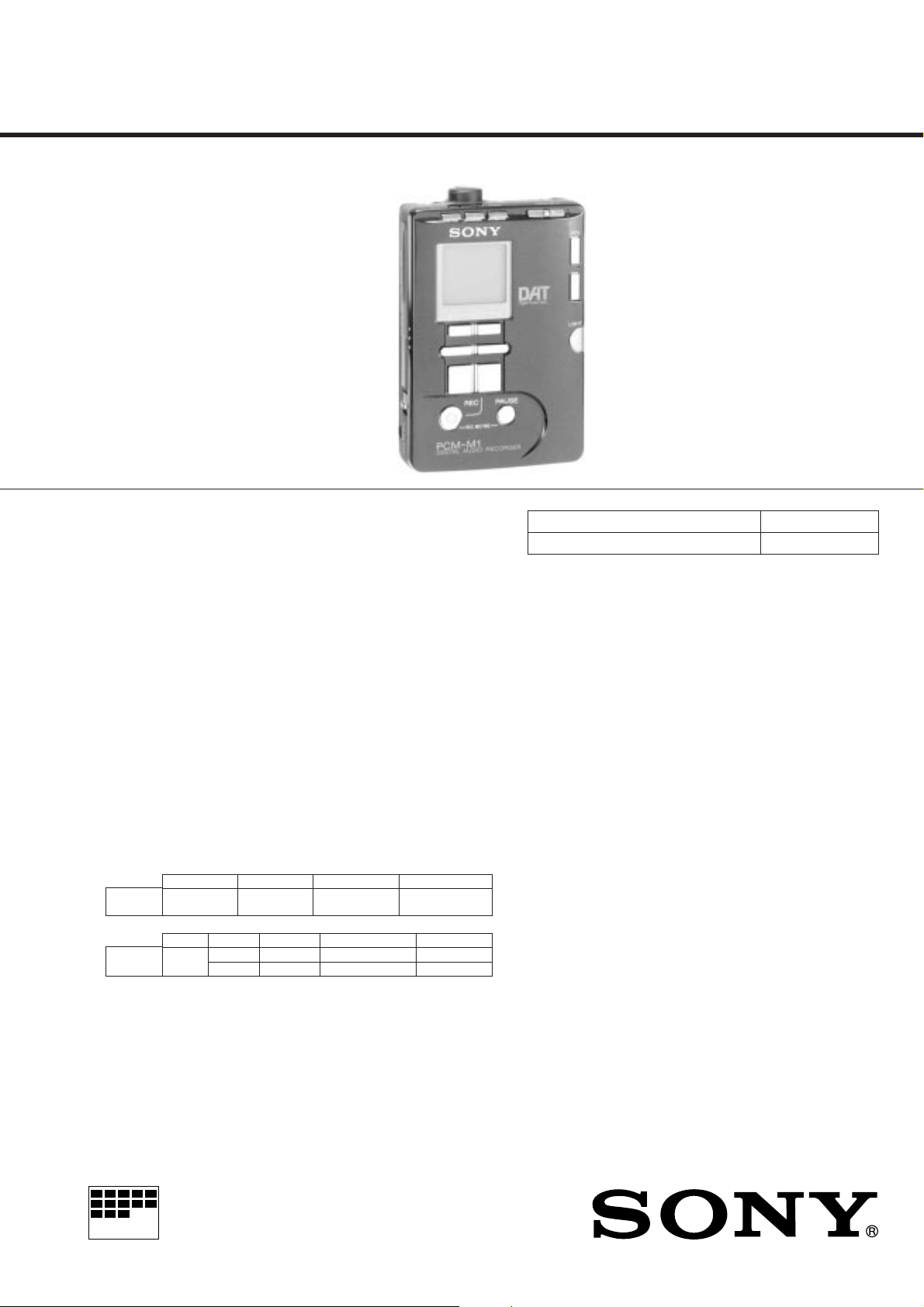
PCM-M1
SERVICE MANUAL
SPECIFICATIONS
Tape Digital audio tape
Recording time Standard: 120minutes
Sampling frequency 48kHz, 44.1kHz, 32kHz
Quantization Standard: 16-bit linear
Frequency response
Signal to noise ratio Standard: more than 87dB
Dynamic range Standard: more than 87dB
Total harmonic distortion
Wow and flutter
Input
MIC/
LINE IN
Output
LINE OUT
REMOTE /2
Input/Output DIGITAL • REMOTE I/O jack (special jack)
Jack type
stereo minijack
Jack type
stereo
minijack
Long-play mode: 240minutes (with DT-120)
Long-play mode: 12-bit non linear
Standard: Fs 48kHz 20-22,000Hz (±1.0dB) (LINE IN)
Fs 44.1kHz 20-20,000Hz (±1.0dB) (LINE IN)
Fs 32kHz 20-14,500Hz (±1.0dB) (LINE IN)
Long-play mode: Fs32kHz 20-14,500Hz (±1.0dB) (LINE
IN)
Long-play mode: more than 87dB
(1kHz IHF-A, LINE IN)
(1kHz IHF-A, LINE IN)
Standard: less than 0.008% (1kHz, 22kHz LPF, LINE IN)
Long-play mode: less than 0.09% (1kHz, 22kHz LPF,
LINE IN)
Below measurable limit (less than ±0.001% W.PEAK)
Impedance
220Ω
16Ω
Impedance
MIC 4.7kΩ
LINE IN 47kΩ
Rated output
500mV
87mV
Rated input level
MIC 1.4mV
LINE IN 500mV
Minimum output level
–
15mW+15mW
Minimum input level
MIC 0.3mV
LINE IN 120mV
Load impedance
10kΩ
16Ω
AEP Model
US Model
t
w
Model Name Using Similar Mechanism TCD-D100
Tape Transport Mechanism Type MT-D100-128
Digital input/ output, remote control operation and
timer-activated operation is possible by connection
with an adaptor kit to this jack.
Power requirements • Two R6 (size AA) alkaline batteries (not supplied)
Battery life See “Replacing the batteries” (page 11).
Power consumption 0.9W
Dimension Approx. 80×117.3×29.2mm (3
Mass Main unit: Approx. 290g (10.3oz)
Supplied accessories
• AC power adaptor (1)
• Charger adaptor (1)
• Nickel Metal Hydride Rechargeable battery NH-D100 (2)
• Headphones with a remote control (1)
• DAT cleaning cassette (1)
• Microphone plug adaptor (monaural phone jack × 2→ stereo miniplug) (1)*
• Optical cable (special jack ↔ rectangular-shaped optical input/output) (1)*
• Battery carrying case (1)
• Carrying case (1)
* Supplied only to the European model.
Design and specifications are subject to change without notice.
• Two nickel metal hydride rechargeable battery
(Supplied)
DC IN 4.5V jack accepts:
the Sony AC power adaptor AC-E45HG
(Supplied)
the car battery cord DCC-E245 (not supplied)
for use with 12V/24V car battery.
1
5
3
× 4
× 1
/
(w/h/d) not incl. projecting parts and controls
When using the main unit: Approx. 395g (14oz.)
incl.headphones with remote control, rechargeable
batteries and a cassette
4
in)
/
/
8
16
MICROFILM
DIGITAL AUDIO TAPE RECORDER

TABLE OF CONTENTS
1. GENERAL································································
2. DISASSEMBLY
2-1. P ANEL ASSY, LOWER ··················································· 14
2-2. MAIN BOARD ································································14
2-3. LID ASSY , CASSETTE ··················································· 15
2-4. PC BOARD UNIT, SYSTEM CONTROL ······················ 15
2-5. CABINET········································································· 16
2-6. BRACKET ASSY, MD ···················································· 16
2-7. CHASSIS ASSY······························································· 17
2-8. DRUM ASSY ···································································17
3. ADJUSTMENTS
3-1. ADJUSTMENTS······························································ 18
3-2. MECHANICAL ADJUSTMENTS ·································· 23
3-3. ELECTRICAL ADJUSTMENTS ···································· 24
4. DIAGRAM
4-1. BLOCK DIAGRAM – MD SECTION — ······················· 26
4-2. BLOCK DIAGRAM – AUDIO SECTION —·················29
4-3. IC BLOCK DIAGRAM ···················································31
4-4. PRINTED WIRING BOARD ··········································34
4-5. SCHEMATIC DIAGRAM —MAIN SECTION —········· 39
4-6. SCHEMATIC DIAGRAM —AUDIO SECTION — ······ 42
4-7. IC PIN FUNCTION ·························································45
5. EXPLODED VIEWS
5-1. CABINET SECTION ·······················································49
5-2. CASSETTE HOLDER SECTION ··································· 50
5-3. MACHANISM SECTION 1 ············································ 51
5-4. MACHANISM SECTION 2 ············································ 52
3
6. ELECTRICAL PARTS LIST ···································53
Notes on chip component replacement
• Never reuse a disconnected chip component.
• Notice that the minus side of a tantalum capacitor may be
damaged by heat.
Flexible Circuit Board Repairing
• Keep the temperature of soldering iron around 270˚C
during repairing.
• Do not touch the soldering iron on the same conductor of the
circuit board (within 3 times).
• Be careful not to apply force on the conductor when soldering
or unsoldering.
— 2 —
SECTION 1
GENERAL
This section is extracted
from instruction manual.
— 3 —
— 4 —
— 5 —
— 6 —
— 7 —

— 8 —
— 9 —
— 10 —
— 11 —
— 12 —
— 13 —
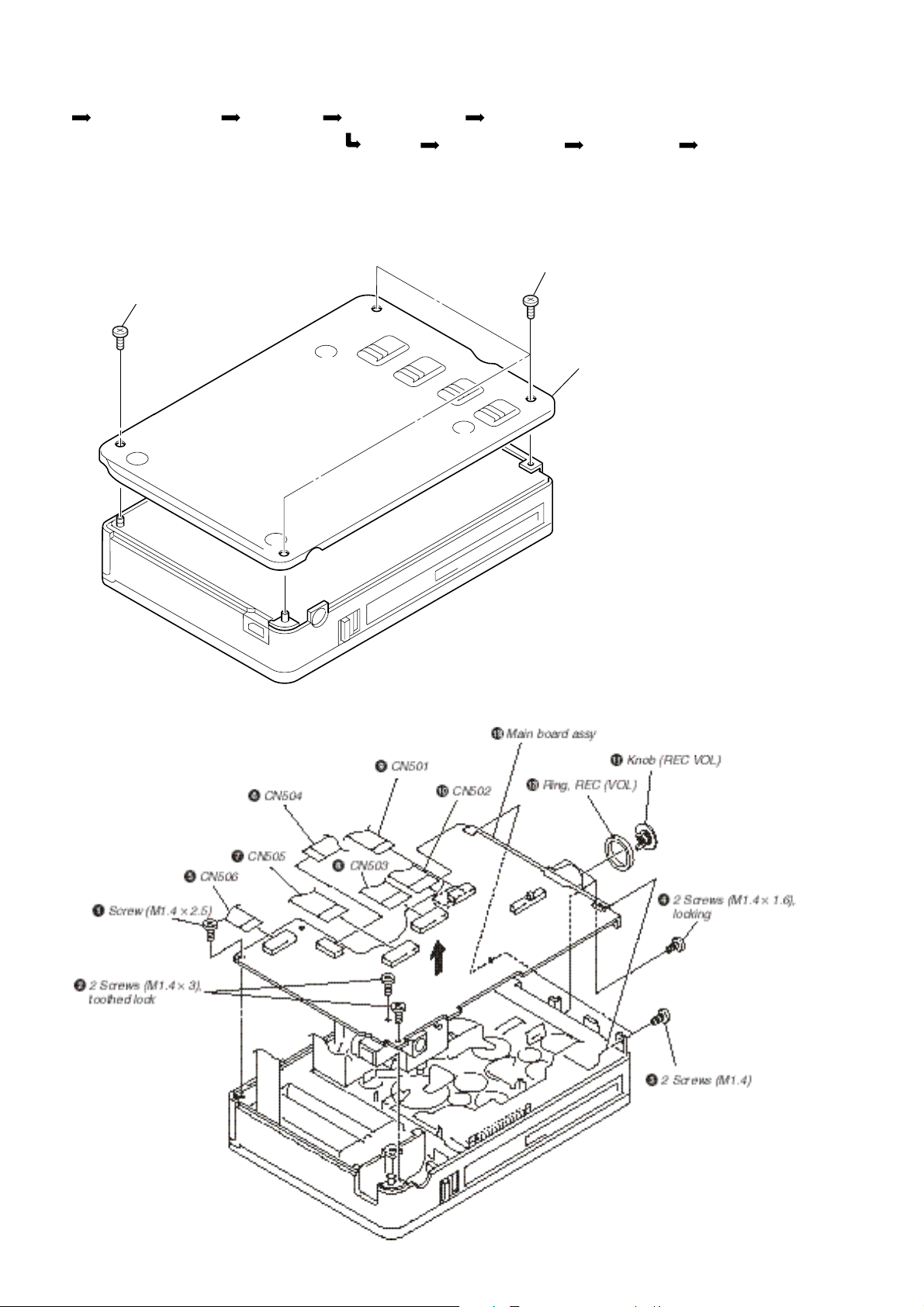
SECTION 2
DISASSEMBLY
SET PANEL ASSY, LOWER MAIN BOARD LID ASSY, CASSETE PC BOARD UNIT, SYSTEM CONTROL
CABINET BRACKET ASSY, MD CHASSIS ASSY DRUM ASSY
2-1. PANEL ASSY, LOWER
Note: When assembling it, align the slide switch position, and
assemble it.
2
3 Screws (M1.4 × 1.6)
1 Screw (M1.4 × 2.5)
3
Panel assy, lower
2-2. MAIN BOARD
— 14 —
 Loading...