

Page 1

Linear PCM
Recorder
Operating Instructions
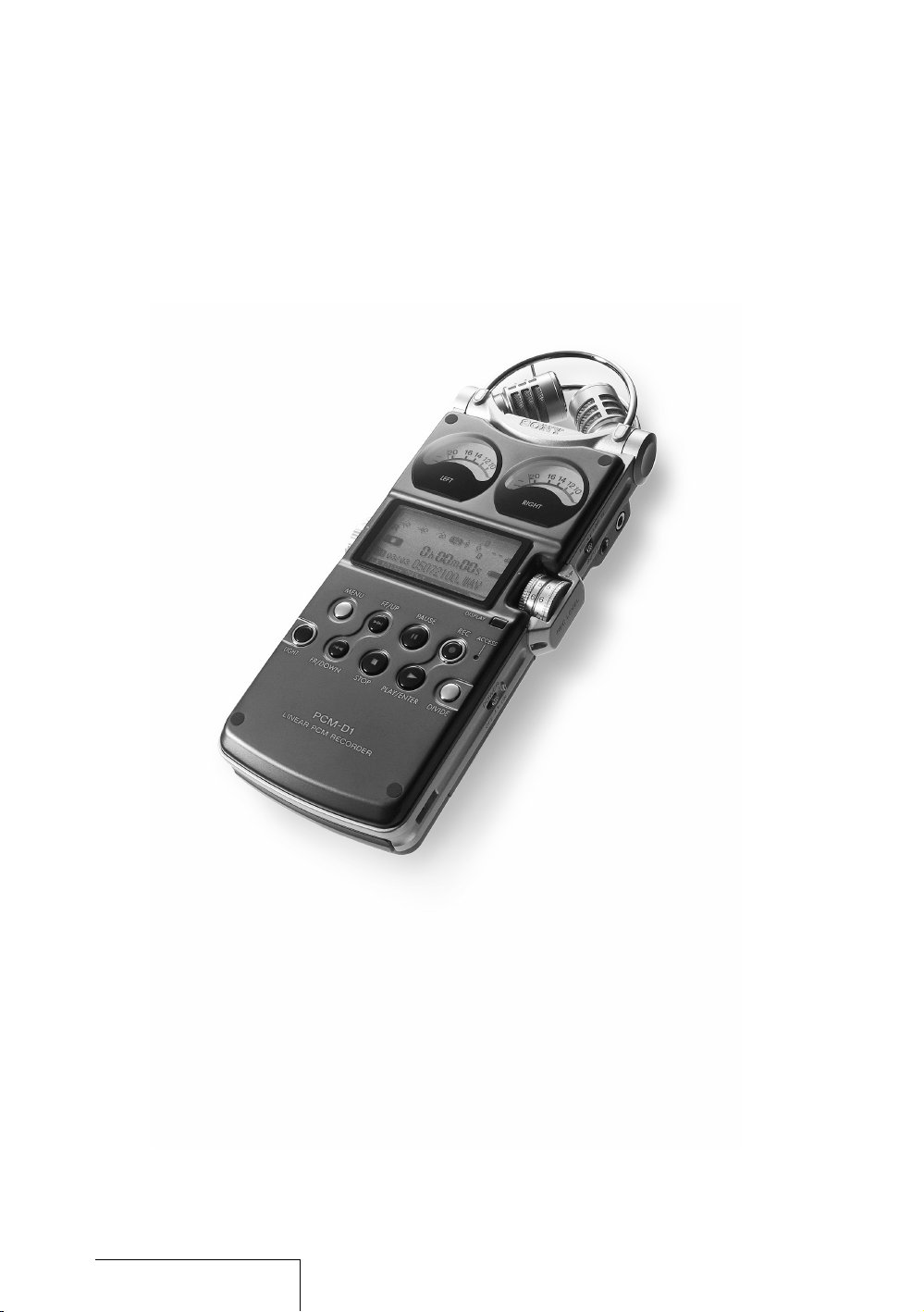
PCM-D1
© 2005 Sony Corporation
2-664-971-11(1)
Page 2

Owner’s Record
The model number is located at the rear and
the serial number is located inside the
battery compartment. Record the serial
number in the space provided below. Refer
to them whenever you call upon your Sony
dealer rega rdi ng this product.
Mod el No. PCM -D1
Ser ial No.
WARNING
To reduce the risk of fire or electric shock,
do not expose this apparatus to rain or
moisture.
Do not install the appliance in a confined
space, such as a bookcase or built-in
cabinet.
To reduce the risk of fire, do not cover the
ventilation of the apparatus with newspapers,
tablecloths, curtains, etc. And do not place
lighted candles on the apparatus.
To reduce the risk of fire or electric shock,
do not place objects filled with liquids, such
as vases, on the apparatus.
Certain countries may regulate disposal of
the battery used to power this product.
Please consult with your local authority.
If you have any questions about this product,
you may call:
Sony Customer Information Services Center
1-800-222-7669 or http://www.sony.com/
Declaration of Conformity
Trade Name: SONY
Model: PCM-D1
Responsible Party: Sony Electronics Inc.
Address: 16 450 W. Bernardo Dr,
San Diego, CA
92127 U.S.A.
Telephone Number: 858-942-2230
This device complies with part 15 of the
FCC Rules. Operation is subject to the
following two conditions: (1) This device
may not cause harmful interference, and
(2) this device must accept any
interferenc e received, including
interferenc e that may cause undesired
operation.
Information
IN NO EVENT SHALL SELLER BE LIABLE
FOR ANY DIRECT, INCIDENTAL OR
CONSEQUENTIAL DAMAGES OF ANY
NATURE, OR LOSSES OR EXPENSES
RESULTING FROM ANY DEFECTIVE
PRODUCT OR THE USE OF ANY
PRODUCT.
Product registration
Please regi ster this product on line at
www.sony.com/productregistration
<http://www.sony.com/productregistrati on>
Proper registration will enable us to send you
periodic mailings about new products,
services and other important
announcements. Registering your product
will also allow us to contact you in the
unlikely event that the product needs
adjustment or modification.
Thank you.
Page 3

Information
This equipment has been tested and found
to comply with the limits for a Class B digital
device, pursuant to Part 15 of the FCC
Rules.
These limits are designed to provide
reasonable pro tection against harmful
interferenc e in a residential installation. This
equipment generates, uses, and can radiate
radio frequ ency energy and, if not installed
and used in accordance with the
instructions, may cause harmful interference
to radio communications.
However, there is no guarantee that
interferenc e will not occur in a particular
installation. If this equipment does cause
harmful interference to radio or television
reception, which can be determined by
turning the equipment off and on, the user is
encouraged to try to correct the interference
by one or more of the following measures:
– Reorient or relocate the receiving ant enna.
– Increase the separation between the
equipment and receiver.
– Connect the equipment into an outlet on a
circuit different from that to which the
receiver is connected.
– Consult the dealer or an experienced
radio/TV technician for help.
You are cautioned that any changes or
modifications not expressly approved in this
manual could void your authority to operate
this equipment.
RECYCLING NICKEL METAL HYDRIDE
BATTERIES
Nickel Metal Hydride batteries
are recyclable .
You can help preserve our
environment by returning your
used rechar geable batteries to
the collection and recycling
location nearest you.
For more in formation regarding recycling of
rechargeabl e batteries, call toll free
1-800-822-8837, or visit
http://www.rbrc.org/
Caution: Do not handle damaged or leaking
Nickel Metal Hydride batteries.
On this manual
These operating instructions are written
mainly for models outside of Japan. In the
case of the model for use in Japan, the
display indications may differ slightly, but
operations are identical.
Page 4

IMPORTANT
SAFEGUARDS
For your protection, please read these safety
instructions completely before operating the
appliance, and keep this manual for future
reference.
Carefully o bserve all warnings, precautions
and instructions on the appliance and in the
operating instructions, and adhere to them.
INSTALLATION
Water and Moisture – Do not use powerline
operated appliances near water – for
example, near a bathtub, washbowl, kitchen
sink, or laundry tub, in a wet basement, or
near a swimming pool, etc.
Heat – Do not place the appliance near or
over a radiator or heat register, or where it is
exposed to direct sunlight.
Ventilation – The slots and openings in the
cabinet are provided for necessary
ventilation. To ensure reliable operation of
the appliance, and to protect it from
overheating, these slots and openings must
never be blocked or covered.
– Never cover the slots and openings with a
cloth or other materials.
– Never block the slots and openings by
placing the appliance on a bed, sofa, rug
or other similar surface.
– Never place the appliance in a confined
space, such as a bookcase, or built-in
cabinet, unless proper ventilation is
provided.
Accessories – Do not place the appliance
on an unstable cart, stand, tripod, bracket,
or table. The appliance may fall, causing
serious injury to a child or an adult, and
serious damage to the appliance. Use only a
cart, stand, tripod, bracket, or table
recommended by Sony.
USE
Power Source – This appliance should be
operated only from the type of power source
indicated on the marking label. If you are not
sure of the type of electrical power supplied
to your home, consult your dealer or local
power company. For those appliances
designed to operate from battery power, or
other sourc es, refer to the operating
instructions.
Grounding or Polarization – This appliance
is equipped with a polarized AC power cord
plug (a plug having one blade wider than the
other), or with a three-wire grounding type
plug (a plug having a third pin for grounding).
Follow the instructions below:
•
For the appliance with a polarized AC
power cord plug:
This plug will fit into the power outlet only
one way. This is a safety feature. If you are
unable to insert the plug fully into the
outlet, try reversing the plug. If the plug
should still fail to fit, contact your
electrician to have a suitable outlet
installed. Do not defeat the safety purpose
of the polarized plug by forcing it in.
•
For the appliance with a three-wire
grounding type AC plug:
This plug will only fit into a grounding-type
power outlet. This is a safety feature. If you
are unable to insert the plug into the outlet,
contact your electrician to have a suitable
outlet installed. Do not defeat the safety
purpose, of the grounding plug.
Overloading – Do not overload wall outlets,
extension cords or convenience receptacles
beyond their capacity, since this can result in
fire or ele ctric shock.
When not in use – Unplug the power cord of
the appliance from the outlet when left
unused for a long period of time.
To disconnect the cord, pull it out by
grasping the plug. Never pull the plug out by
the cord.
Page 5

Power-Cord Protection – Route the power
cord so tha t it is not likely to be walked on
or pinched by items placed upon or against
them, paying particular attention to the
plugs, rece ptacles, and the point where the
cord exits fro m the appliance.
Lightning – For added protection for this
appliance during a lightning storm, or when
it is left unattended and unused for long
periods of time, unplug it from the wall outlet
and disconnect the antenna or c able system.
This will prevent damage to the appliance
due to lightning and powerline surges.
Attachments – Do not use attachments not
recommended by Sony, as they may cause
hazards.
Cleaning – Unplug the appliance from the
wall outlet before cleaning or polishing it. Do
not use liquid cleaners or aerosol cleaners.
Use a cloth lightly dampened with water for
cleaning the exterior of the appliance. Clean
the appliance only as recommended by
Sony.
Object and Liquid Entry – Never push
objects of any kind into the appliance
through ope nings as they may touch
dangerous v oltage points or short out parts
that could result in a fire or electric shock.
Never spill liquid of any kind on the
appliance.
SERVICE
Damage Requiring Service – Unplug th e
appliance from the wall outlet and refer
servicing to qualified service personnel under
the following conditions:
– When the power cord or plug is damaged
or frayed.
– If liquid has been spilled or objects have
fallen into the appliance.
– If the appliance has been exposed to rain
or water.
– The appliance does not appear to operate
normally or exhibits a marked change in
performance. – This indicates a need for
service.
– If the appliance does not operate normally
when following the operating instructions,
adjust only those controls that are
specified in the operating instructions.
Improper ad justment of other controls may
result in d amage and will often require
extensive work by a qualified technician to
restore the ap pliance to normal operation.
– If the appliance has been subject to
excessive shock by being dropped, or the
cabinet has been damaged.
Servicing – Do not attempt to service the
appliance yourself as opening or removing
covers may expose you to dangerous
voltage or other hazards. Refer all servicing
to qualified service personnel.
Replacement parts – When replacement
parts are requ ire d, be sure the service
technician has used replacement parts
specified by Sony that have the same
characteristics as the original parts.
Unauthorized substitutions may result in fire,
electric shock, or other hazards.
Safety Check – Upon completion of any
service or repairs to the appliance, ask the
service technician to perform routine safety
checks (as specified by Sony) to determine
that the appliance is in safe operating
condition.
Page 6

Table of Contents
Overview
Built-in microphones—Pick up sound ................................................................... 10
Electrical circuit—Amplifies sound ........................................................................... 11
Exterior—Increase rigidity .............................................................................................. 12
Identifying parts and controls ....................................................................................... 14
Getting Started
Checking the supplied accessories .......................................................................... 18
Step 1: Preparing a power source .............................................................................19
Step 2: Setting the clock ................................................................................................. 21
Recording
Preparation before recording ........................................................................................ 22
Recording...................................................................................................................24
Monitoring the recording .................................................................................................. 26
Recording with an external microphone ................................................................27
Recording from external equipment .........................................................................27
Operations after Recording
Playing back recorded audio data (tracks) ........................................................... 28
Dividing a track ...................................................................................................................... 30
Storing tracks in a computer .........................................................................................30
6
Page 7

Menu Operations
Using the menu display .................................................................................................... 34
Menu items ............................................................................................................................... 35
REC MODE (Sampling frequency/quantifying bit number)
LIMITER (Preventing distortion)
200Hz HPF (High Pass Filter function)
SBM (Super Bit Mapping function)
DELETE TRK (Deleting track)
DELETE ALL (Deleting all tracks in folder)
FORMAT (Initializing memory)
LED (Indicator lighting)
CLOCK (Date/time setting)
MEMORY (Recording/playback memory)
FOLDER (Recording/playback folder)
Additional Information
Using a “Memory Stick PRO (High Speed)” (not supplied) ....................... 38
Maintenance ............................................................................................................................40
Troubleshooting .....................................................................................................................41
Specifications .......................................................................................................................... 46
File specifications ................................................................................................................. 48
Index.............................................................................................................................50
7
Getting StartedOverview Recording
Operations after
Recording
Menu Operations
Additional Information
Page 8
Overview
8
Page 9

PC M -D1 comb i nes thes e fe a tur es f or
re cord ings tha t ar e fa ithf u l t o the ori g ina l so u nd
an d re p rod uce e ven the subt lest of n uanc es.
— A s tru ctu re fre e o f dr ive me cha n ism s
— Hig hly se nsit ive , b uilt -in co nden ser mi cro pho nes
— Circui ts tha t p roc ess sou nd wit h li ttl e n oise
— Bod y m ade of pre sse d t ita nium wi th mini mal jo ins
9
Overview
Page 10
Overview (continued)
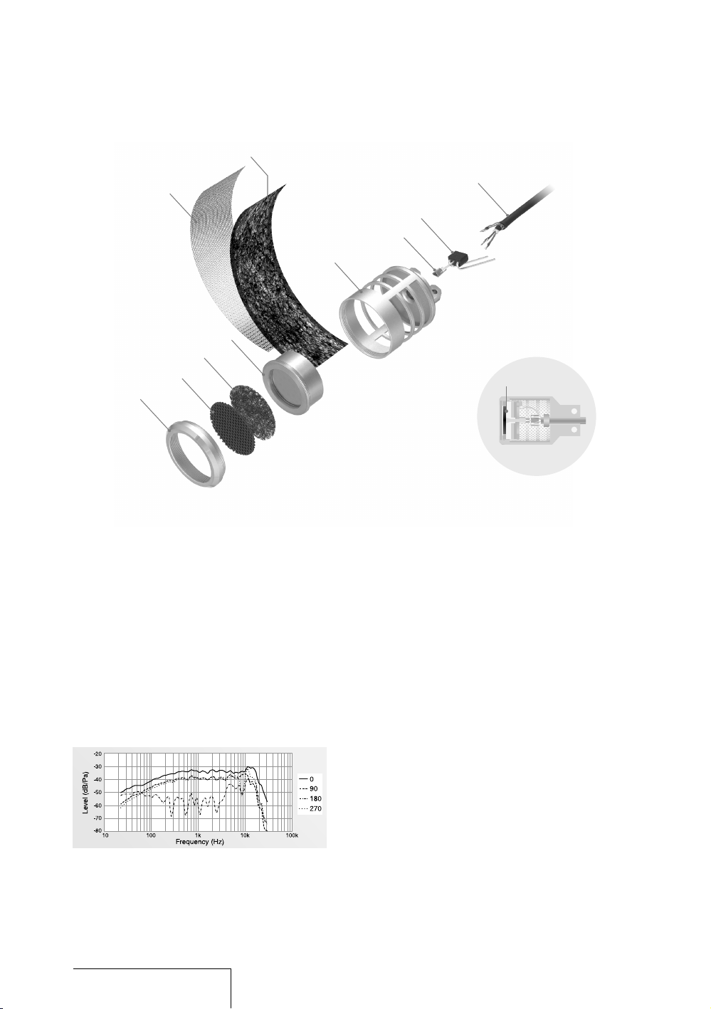
Built-in microphones—Pick up sound
PCM-D1 incorporates electret condenser
microphones that were developed for their
high sensitivity and low noise. Unlike tape or
disc recorders , PCM-D1 has no drive
mechanism and is free of motor noise. This
makes it possible to employ a highly sensitive
microphone to be used as a component.
All microph one casing parts are cut from
metal and fit together nearly seamlessly.
Each part is positioned and the front and
rear openin gs are adjusted with 100-micron
level preci sion. Peaks and dips in the
microphone’s range are minimized so that
Sec tion view of microphon e
Fig ure 1: Built-i n microphone, fre quency
response
Cap
Front gril l
Top sc reen
Mic rophone un it
Sid e mesh
Sid e scree n
Mic rophone ca sin g
Con tactor
FET
Mic rophone co rd
Dia phragm
acoustic energy is transmitted effectively to
the diaphragm in the microphone unit.
To ensure that sound is then converted to
electrical signals, the conditions for
manufacturing the electret (charging the
diaphragm to increase sensitivity to subtle
sounds) were reviewed—resulting in a
sensitivity nearly 6 dB superior to that of a
standard mi cro phone.
In addition, the frequency response of the
microphone is improved to nearly –30 kHz,
achieving a sampling rate of 96 kHz
(Figure 1). This performance is barely
affected ev en when the supplied windscreen
is used.
The microph ones are positioned using the XY patter n and then angled toward each other
with the left and right diaphragms close
together, thereby covering a wide sound
range and reducing phase shifts. The
recorded sound has depth and perspective
and project s a natural stereo image.
Angl e
10
Page 11
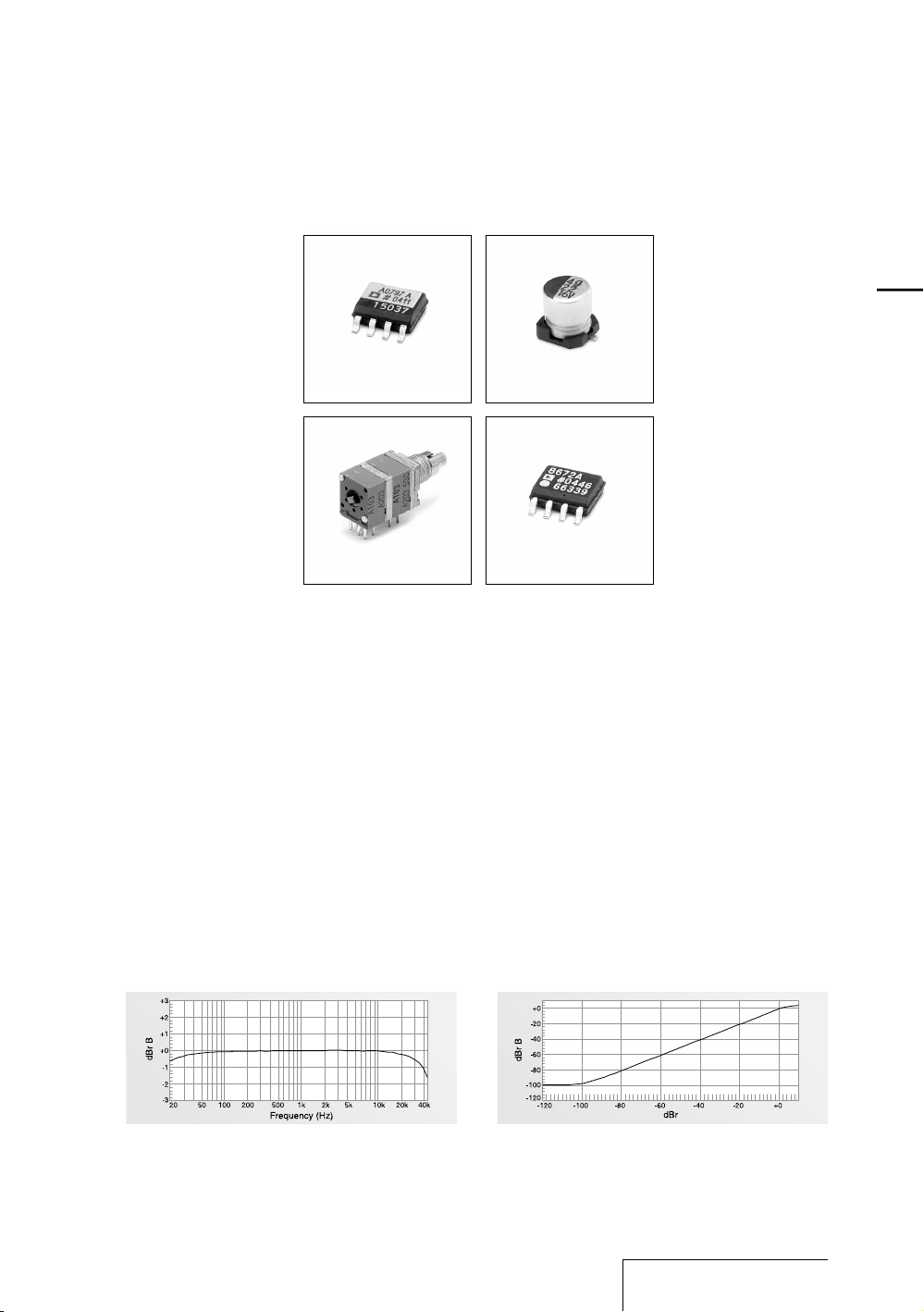
Electrical circuit—Amplifies sound
Lin e amplifier
Sound picked up by the microphones is
amplified in the analog circuit, which
achieves a frequency response that reaches
the high frequencies (Figure 2) and enables
the wide dynamic range of PCM-D1.
The microph one amplifier provided for each
channel is Analog Devices’ AD797, which
boasts ultra-low noise and distortion.
A variable gain circuit is adopted for
amplitude control, thus improving the actual
signal-to-noise ratio.
In the signal line, direct current is removed
by Elna’s coupling condenser, which has a
separator made of synthetic mica mix paper.
A dual-shaft, quad-unit volume control with
ten times the life of a standard volume control
was developed for recording. Special carbon
ink is applied to the resistor in the control to
suppress no ise produced by sliding.
Like the microphone amplifier, the line
amplifier, AD8672, is provided by Analog
Devices.
Interferenc e between blocks is prevented by
placing the analog circuit on a different
board from dig ital circuits and providing
separate ± power. The analog circuit also
achieves superior linearity so that the
recorded sound is output faithfully (Figure 3).
Fig ure 2: Electri cal circuit, freq uency response Fig ure 3: Electri cal circuit, linearity
Mic rophone am pli fie r Cou pling condenser
Dua l-shaft, quad-unit
vol ume
11
Overview
Page 12

Overview (continued)
Exterior—Increase rigidity
The electrical circuits are protected by a
body made of 1 mm thick pure titanium. By
means of a pressing process called
“drawing,” titanium is shaped into a box to
achieve a body rigidity that cannot be
obtained through bending or using pressed
aluminum. The use of drawn titanium
minimizes resonance, which tends to occur
when the body comes into contact with
acoustic energy.
The surface of pure titanium material
undergoes a process that increases the
hardness of the material. The surface is then
covered wit h ion plating (a nitrate titanium
coating that is resistant to scratches). The
finished titanium surface is approximately ten
times as hard as that of alumite treated
aluminum.
The distinctive arch-shaped frame
(microphone guard) protects the built-in
microphone units against impact damage
when droppe d. Exhaustive tests were carried
Front/back panels
(1 mm thick press ed titan ium)
out seeking a form and material that were
rugged enough without obstructing sound.
The final choice: stainless steel rods
(SUS316), 3 mm in diameter, bent into the
shape of the frame and hand polished by
skilled craftsmen.
The rugged exterior produced in this way
protects th e circuits and microphones and
enhances the high recording quality of
PCM-D1.
Mic rophone guard (SUS316 stainless stee l rod)
12
Page 13

13
Overview
Page 14

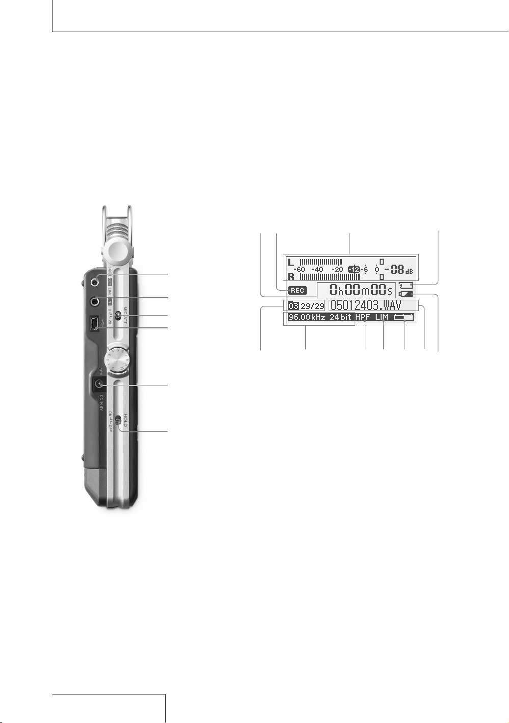
Identifying parts and controls
Front
Right side
Overview (continued)
14
Page 15

Built-in microphones (page 22)
Analog level meters (page 25)
Displays left and right volume levels of an
audio signal input from microphones in
analog values.
Display (page 16)
VOLUME dial
Adjusts the playback volume when turned in
+/– directi ons.
FF (fast-forward) /UP button
(pages 21, 29)
MENU button (page 34)
LIGHT button
Turns on or off the backlight of the display
and the analog level meters.
FR (fast-rewind) /DOWN button
(pages 21, 29)
REC LEVEL L/R (recording level left/right)
dials (page 24)
DISPLAY button (page 17)
Switches time information in the display.
PAUSE button/indicator (pages 25, 29)
ACCESS indicator (pages 20, 38)
Flashes when accessing memory (except
during reco rdi ng).
REC (recording) button/indicator
(page 24)
DIVIDE button (page 30)
PLAY/ENTER button/indicator
(pages 21, 28)
STOP button (pages 25, 29)
MIC (microphone) jack (page 27)
(headphone) jack (pages 26, 28)
MIC (microphone) /LINE IN switch
(page 24)
When set to “MIC,” records an audio signal
input from the built-in microphones or an
external microphone that is connected to the
MIC jack. When set to “LINE IN,” records an
audio signal output from external equipment
that is connected to the LINE IN jack.
Memory Stick slot (page 38)
POWER switch
Turns on or off the power.
Battery compartment lid (page 19)
Slit for a wrist strap (page 18)
Continued on the next page
15
Overview
Page 16
Left side
Overview (continued)
Display
16
Page 17

LINE OUT/optical DIGITAL OUT jack
(page 29)
LINE IN jack (page 27)
MIC ATT (microphone attenuator) switch
(page 23)
USB connector (page 30)
DC IN 6V jack (page 20)
HOLD switch
When set to “ON,” the buttons on the
recorder are lock ed to prevent accidental
operation. It is recommended to set to “ON”
during reco rdi ng and playback. To unloc k
the control s, set to “OFF.”
Time information
Each time the DISPLAY button is pressed,
the time information changes as follows
(Flashes when the recorder is paused):
Elapsed rec ord ing/playback time
Remaining recordable time of the current
memory (During playback: Remaining
time of the current track)
Recorded date
(During record ing: Recording start date)
Recording/playing status
Displays as follows according to the current
operation:
Recording
(Flashing)
Recording pause,
standby for recording
Playback
(Flashing)
Playback pause
Stop
/
Fast reverse/forward
/
Go to previous/succeeding
tracks
Peak meter (page 25)
Memory Stick indicator
Displayed when the current memory is a
“Memory Stick PRO (High Speed).”
Folder number, track numbers
Track numbers are displayed as “current
track number/total numbers of tracks.”
Sampling frequency and quantifying bit
number of currently recording/playing
track (page 35)
HPF (High Pass Filter) setting
Displayed when “200Hz HPF” is set to “ON”
(page 36).
Limiter setting
Displayed when “LIMITER” is set to “ON”
(page 35).
Remaining memory volume
Displayed the remaining volume of current
memory (page 26).
File name of currently recording/playing
track
Remaining battery power (page 20)
17
Overview
Page 18

Checking the supplied accessories
•
Size AA (LR06) battery
case
•
CD-ROM
(“DigiOnSound5”* and
“Driver for W indows
2000”)
* For instructions, refe r t o the
hel p function of each
app lication.
•
Operating Instructions
(this book)
Getting Started
•
Windscreen (page 23)
•
AC power adaptor (6V)
(page 20)
•
USB cable (page 30)
•
Carrying case
•
Wrist strap
•
Charging set (page 19)
(Battery charger BCG34HRE, four size AA
(LR06) nickel metal
hydride rec hargeable
batteries NH-AA)
To use the wrist strap
Attach the wrist strap to the slit for the wrist strap on the right
side of the recorder.
When an optional headphone, exter nal microphone, audio
cable, etc., is connected to the recorder (pages 26 to 29), slip
the cord(s) through the wrist strap and tighten the stopper as
shown below. This prevents the cord(s) from being accidentally
pulled out.
Ins ert the
cord.
Loo sen the
sto pper.
Loo p the cord
around and insert it
aga in, and then
tig hten the stopper.
18
Page 19

Step 1: Preparing a power source
Use the supplied size AA (LR06) nick el metal
hydride rec hargeable batteries after charging
them.
1
Insert the four rechargeable batteri es into
the battery charger (supplied).
Be sure to insert the rechargeable
batteries with the and ends in t he
right position.
Ope n the lid
of the battery
cha rger.
2
Connect the battery charger to a wall
outlet.
The CHARGE lamps light up during
charging. Charging takes about 5 hours.
(The charging time varies depending on
the temperature.)
Fou r CHARGE lamps
3
When charging is completed, the
CHARGE lamps turn off. Remove the
rechargeabl e batteries from the battery
charger.
Note that the rechargeable batteries and
the battery charger emit some heat
during charging.
4
Open the battery compartment lid on the
rear of the re corder.
Fir st slide the lid
dow nward and then
ope n it.
5
Pull out the battery case from the
recorder.
Pus h the buttons on
bot h sides to pull out.
Bat tery case
6
Insert four batteries into the ba ttery case.
Be sure to insert the batteries with the
and ends in the right position.
7
Insert the battery case back into the
recorder, and close the batte ry
compartment lid.
To use the recorder with size AA (LR06)
alkaline batteries
The recorder c an operate on size AA (LR06)
alkaline batteries. Follow steps 4 to 7.
Note
• Turn off t he reco rder power before t aking out the
bat tery case.
• Charg e t he bui lt- in battery at a temperatu re of 0°C
to 35°C (32°F to 95°F). The cha rgi ng tim e will vary
acc ording to the room temperature. (If the ro om
tem perature i s l ow, the req uired chargin g t ime wi ll
be longer. This is a cha rac ter ist ic of the Nickel Metal
Hyd ride battery.)
Continued on the next page
19
Getting Started
Page 20

When you turn on the recorder for the first
time after purchasing
When the POWER switch is set to the “ON”
position, “ACCESSING MEMORY” appears
in the display, and the ACCESS indicator
flashes. Information for operation is read in
the recorder’s built-in memory. Then, the
display changes to the clock set menu to
enable you to set the clock.
When to charge or replace the batteries
When using nickel metal hydride
rechargeabl e batteries, the remaining battery
power is indicated in the display.
The indicator also appears when using
alkaline batteries, but it may differ from the
actual rema ining power.
There is su ffi cient battery power.
Charge or replace all four batteries.
There is no power left .
The recorder w ill not operate.
Battery life (Approximate continuous
recording/playback time)*
Type of battery
96 kHz 24 bit 44 kHz 16 bit
Nickel metal hydride
rechargeable
batteries (supplied)
4.0 hours 5.0 hours
Alkaline batteries 2.0 hours 2.0 hours
* App roximat e v alu es for co ntinuous reco rding/
pla yback using Sony size AA (LR 06) ba tte ries under
a t emperature of 20 ºC (68 ºF). The battery capac ity
dec reases and ba tte ry lif e becomes shorter in l ow
tem peratures.
Getting Started (continued)
To operate with the AC power adaptor
Connect the supplied AC power adaptor to
the DC IN 6V jack.
to a wall outlet
AC power
ada ptor
(su pplied)
to the DC IN
6V jack
Notes on the AC power adaptor
Use only the supplied AC
power adaptor. Using any
other AC power adaptor
may cause a malfunction.
Notes
• Durin g c har gin g a nd refreshing, the rech arg eable
bat teries and the battery ch arg er may em it some
hea t, but this is not a malf unc tio n. Not e that the
tem perature i s h igh er rig ht after charging fini she s. It
is recomme nde d t hat yo u w ait for a while before
removing t he bat ter ies .
• Use o nly th e s upp lie d battery charger. Us ing an y
oth er charger may cause a ma lfu nct ion .
• The b att eri es can not be charged with the recorder
onl y without using the batte ry cha rge r.
• Do no t u se a d ry bat tery and a re cha rge able battery
tog ether.
• The recorder is ac ces sin g memory while
“AC CESSING MEMORY” app ear s i n the display or
the ACCESS indicator flashes . D uri ng thi s time, do
not remove or in ser t b att eries and do not
dis connect or connect the AC po wer ad apt or, or the
USB cable. Doing so may dama ge the da ta.
• Becau se of the ba tte ry’s c har acteristics, the
cap acity of the rec har gea ble batteries may be
sma ller than normal when the y a re used for the fir st
tim e or after a long period of dis use . I n this case,
cha rge and discharge them se ver al tim es. The
nor mal battery life will be restore d.
• I f the life of the rech argeable batteries drops to half
the normal length, the batte rie s s hou ld be repl ace d.
Pol arity of the plug
20
Page 21

Step 2: Setting the clock
Recorded au dio files (tracks) are named
using the date and time of the internal clock.
By setting the clock before recording, the
recording’s date and time will be correctly
saved.
1
When the recorder is turned on before
the clock has been set, “SET CLOCK”
appears in the display. After about 3
seconds, the message disappears
automatically, and the “CLOCK” display
of the menu appears.
2
Press the UP and DOWN
buttons to set the year (y), and press the
ENTER button.
3
Repeat step 2 to set the month (m), day
(d), hour, minute, and second. Then press
the ENTER button after setting the
seconds to start operating the clock.
To reset the clock
1 While the recorder is stopped, press the
MENU button to display the menu.
2 Press the UP and DOWN
buttons to select “CLOCK,” and press the
ENTER button.
The “CLOCK” display appears.
3 Follow steps 2 and 3 of “Step 2: Setting
the clock” to reset the clock.
Note
• If yo u l eav e t he recorde r for more th an
app roximat ely 10 mi nut es with no battery insert ed,
the date and time change to the de fau lt settings. In
thi s case, re set th e c loc k.
21
Getting Started
Page 22

Preparation before recording
When you position the recorder, place it so
that the microphone points to the sound
source. For accurate recording of left and
right sourc es, place the recorder with its
front side facing upward (see the illustration
below).
The placement of the recorder and the
direction o f the microphone depend on the
sound sourc e, the microphone, the settings
of the reco rde r, etc. It is reco mmended that
you try rec ord ing with the recorder in various
positions and settings after referring to the
illustration below and the characteristics of
the microph one.
Example: Placement when recording a
musical performance using the built-in
microphones
For best re sults, place the recorder about 2
to 3 m (6.56 to 9.84 ft) from the sound
source. Ref erring to the characteristics of
the built-in microphones, adjust direction of
the recorder a nd the angle of the
microphones .
Sou nd source
App rox. 2 to 3 m
(6. 56 to 9.84 ft)
Pla ce the rec order with its
front side fa cin g u pwa rd and
the built-in microp hon es
poi nting at the sound source.
On characteristics of the built-in
microphones
The built-in microphones are unidirectional
(see figure 1).
Because the two capsules are in an XY
arrangement, the microphone on the right
records sound fro m the left; the microphone
on the left records sound from the right (see
figure 2).
However, if the sound source is too close to
the microph one, the right microphone
records the ri ght and the left microphone
records the le ft.
100 Hz
400 Hz
1 k Hz
4 k Hz
0º
90º
90º
180 º
Fig ure 1: Directivity of the built-in m icrophones
Rec ords
sou nd from
the right.
Rec ords
sou nd from
the left.
Fig ure 2: Direction of sound that the b uilt-in
mic rophones gathe r
Recording
Tripod ( not supplied)
22
Page 23

To switch the microphone input sensitivity
Use the MIC ATT switch.
Usually set it to the “0” position. When
recording loud sounds, set it to the “20”
position.
To position the recorder using the tripod
(not supplied)
By attaching the tripod (not supplied), you
can adjust angles of the recorder and the
microphones more precisely. It a lso prevents
noise caused when holding the recorder in
your hand.
Attach the tripod to the hole on the back of
the recorder.
Hol e for attaching
the tripod
Tripod ( not supplied)
To use the supplied windscreen
By covering the built-in microphones with
the supplied windscreen, you can reduce
noise caused by wind or breath that directly
hits the microphones.
F
F
L
E
F
T
R
I
G
H
T
M
E
N
U
4
2
3
1
5
3
REC LEVEL
INPUT
MIC
MIC LINEIN
23
Recording
Page 24

Recording
To change sampling frequency, quantifying
bit number, or the memory and folder for a
recording, go to the menu display (page 34).
The default sampling frequency and
quantifying bit number are “44.10 kHz
16 bit.”
1
Position the recorder and the built-in
microphones re ferring to “Preparation
before recording” (page 22).
2
Set the MIC/LINE IN switch to the “MIC”
position.
3
Press the REC button.
The recorder s tands by for recording, and
the PAUSE indicator flashes.
4
Turn the REC LEVEL L/R dials to adjust
the recording levels of the right and left
channels, checking the level on the
display and the analog level meters.
To adjust the level of the right channel
only, pull out the outside (R side) dial
slightly and turn it.
Pul l out the
out side (R side)
dia l only.
Recording (continued)
Bui lt-in micropho nes
PAUSE button /
ind icator
REC LEVEL L/R dials
VOL UME dial
MIC /LINE IN switch
Ana log level meters
RE C button/
ind icator
PL AY button
ST OP button
Pea k level lamps
24
Page 25

You can check the recording l evel on
both the peak meter of the display and
the analog level meters. Adjust the level
closer to –12dB into appropriate range
that is suitable for your sound source.
When checking the level on the peak
meter of the display
When recording sound that has “quick
attack” parts such as percussive sound,
use the peak meter to check the level.
If appears when the maximum
peak value is output, distortion may
occur.
Pea k indicator (crest val ue
of input signal)
Max imum peak value
When checking the level on the analog
level meters
The input signal is displayed in analog
values. You can see the value close to
the magnitude of volume that the human
ear can hear.
If the peak level lamp lights up in red
(when the recording level exceeds –1dB),
distortion may occur.
Pea k level lamps
Green: Disto rti on wil l n ot occur.
(Recordi ng lev el is –12 to –1dB.)
Red : Recordin g l eve l is more tha n
–1d B.
Low er the level.
5
Press the PAUSE or PLAY button.
The standby for recording is released,
and recording starts. The REC
indicator lights up while recording.
To stop recording
Press the STOP button.
To pause recording
Press the PAUSE button. The PAUSE
indicator flashes.
The recorder d oes not start recording
automatically. Be sure to pre ss the PAUSE
button again to restart or stop recording.
When recording level adjustment is
unnecessary
In step 3, press the PLAY button while
pressing an d holding the REC button.
Recording s tarts immediately.
Notes
• While th e RE C indicator is lit, do no t remove the
bat teries or the AC power ad apt or. Doing so may
dam age the data.
• If th e recorder remains in stop mo de for ab out 10
min utes or longer, th e recorder wi ll enter low-power
con sumption mode automatical ly.
• Noise ma y b e recorded if an object, such as yo ur
fin ger, etc., acci den tal ly rub s o r scratches the
recorde r d uring reco rding.
• Do no t c onn ect th e U SB cable to the rec order
dur ing rec ording. Doing so stops record ing
aut omatically (because conne cti on wit h a computer
has priority).
• For recordin g w ith a sam pling freq uen cy of 96 kHz,
you should format the memory be forehand in order
to write data effic ien tly.
Continued on the next page
25
Recording
Page 26

Recording (continued)
On display of remaining recordable time
Remaining recordable time appears in the
display when the remaining time becomes 5
minutes or less.
Rem aining recordable time
If an operation other than stop recording,
such as fast forward, etc., is done, the
remaining reco rda ble time appears in the
position where remaining memory volume is
usually displayed.
Rem aining recordable time*
When the re maining time runs out,
“MEMORY FULL” appears and recording
stops.
* Whe n the rema ini ng recorda ble time is more th an 5
min utes, the icon that re present s remaining memory
vol ume appears. When memory is unu sed , “ 100%”
app ears.
Monitoring the recording
Connect optional headphones or earphones
to the (headphone) jack of the recorder to
monitor the recording sound. The volume of
monitored s ound can be adjusted by turning
the VOLUME dial.
Hea dphones
(no t supplied)
to the
(he adphone)
jac k
Ste reo mini
plu g
Notes
• If yo u t urn up the volu me exc ess ive ly or place the
hea dphones near the micro phone while monitoring
recordi ng, the micro pho ne may pick up the sound
from the h ead pho nes , c aus ing acoustic feedback
(ho wling sound).
• For b est results, use encap sul ate d-t ype
hea dphones, which have less sou nd lea kag e.
26
Page 27

Recording with an external microphone
You can connect an optional exter nal
microphone to the recorder.
1
Connect an external microphone to the
MIC jack of the recorder, and adjust the
position of the microphone. For
characteristics of the microphone, refer
to the operating instructions supplied
with it.
to the MIC
jac k
Ext ernal microphone
(no t supplied)
2
Follow steps 2 to 5 of “Recording” (page
24) to start recording.
Notes
• When an ext ernal microphone is connected t o t he
recorde r, the built-in mi crophones cannot be us ed
for record ing.
• The recorder do es not su pply power to connecte d
mic rophone (n ot sui tab le for plug-in power). No te
tha t a plug-in power only mi crophone cannot be
use d with the re corder.
Recording from external equipment
You can connect external equipment to the
recorder, for example, to record from a
Super Audio CD/CD player, etc.
1
Connect the audio output jacks of
external equipment to the LINE IN jack of
the recorder b y using an optional Sony
audio cable.
Sup er Audio CD/
CD player
to the LINE
IN jack
Aud io cable (not supplied)
2
Set the MIC/LINE IN switch to the “LINE
IN” position.
3
Follow steps 3 and 4 of “Recording”
(page 24).
4
Start playback of the external equipment.
5
Press the PAUSE or PLAY button
where you w ant to start recording.
The standby for recording is released,
and recording starts.
27
Recording
Page 28

PAUSE button /
ind icator
FR button
DIV IDE button
ST OP button
PL AY button/
ind icator
FF button
Operations after Recording
Playing back recorded audio data (tracks)
To change the memory and folder to play
back, go to the menu display (page 34).
1
Connect optional headphones or
earphones to the (headphone) jack of
the recorder.
Hea dphones
(no t supplied)
to the
(he adphone)
jac k
Ste reo mini
plu g
2
Press the PLAY button.
Playback starts from the first track of the
selected folder or the last point at which
you stopped playback.
The PLAY indicator lights up. All the
tracks in the folder are played in track
number orde r.
28
Page 29

Operations during playback
To Operation
Stop
Press the STOP button.
Pause
Press the PAUSE button.
The PAUSE indicator
flashes. To resume play after
pausing, press the PAUSE
button again.
Fast forward
Press and hold the FF
button.
Fast reverse
Press and hold the FR
button.
Go back to the
beginning of
current track
Press the FR button
once.
Go back to
previous tracks
Press the FR button
repeatedly.
Go to the
beginning of
next track
Press the FF button
once.
Go to the
beginning of
succeeding
tracks
Press the FF button
repeatedly.
Note
• Durin g p lay bac k, do not rem ove th e b att eries or AC
pow er adaptor. Doi ng so may ca use noise in audio
out put fro m t he LIN E O UT jack and (headphone)
jac k.
To connect with external equipment for
playback
To output recorded tracks from spea kers of
external equipment, connect the a udio input
jack or digital input jack of the external
equipment to the LINE OUT/optical DI GITAL
OUT jack of the recorder using an optional
Sony audio cable or optical digital cable.
AV amplifier/pl ayer
to the LINE
OUT /optical
DIG ITAL OUT
jac k
Aud io cable (not supplied)
or
opt ical digital cable (not sup plied)
29
Operations after
Recording
Page 30

Dividing a track
You can divide a recorded tra ck. Note that
tracks cannot be combined on the recorder
after they have been divided.
1
During recording, record pausing,
playback, or playback pausing, press the
DIVIDE button.
The track is divided into two at the point
you pressed the button, and “DIVIDING”
appears in the display.
Notes
• Divid ed tra cks are named as fo llo ws:
– Durin g recordin g/record p aus ing: The new track
wil l have a new name in the sam e w ay as when a
new record ing starts.
– Durin g p lay bac k/p lay back pausing: “_0” is add ed
to the name of the original tra ck, an d “ _1” is
add ed to the name of the new tr ack . H owe ver, if
the original track name is l ess th an 8 b ytes,
und erbars “_” are a dde d t o make a 10-byte
nam e. For example, when divi din g t he fil e named
“12 3.WAV”, the tr acks are n ame d
“12 3______0.WAV” and “123______1.WAV”.
• Trac ks can not be divided if:
– you p ress the button in the po sit ion wi thin less
tha n 0.5 second fro m t he beginning or the end o f
a t rack.
– the t ota l n umb er of recorded track re ach es the
max imum number of reco rdable tra cks (p age 48 ).
(“T RACK FULL” appears in the di spl ay.)
– the n ew tra ck nam e e xceeds the maximum
num ber of characters (227 by tes wi tho ut “.WAV”).
Operations after Recording (continued)
Storing tracks in a computer
Connect the recorder to a computer to save
recorded track s to the hard disk drive of the
computer.
1
Connect the USB connectors of a
computer and the recorder using the
supplied USB connecting cable.
“PC CONNECT” appears in the display of
the recorder, and it is recogniz ed as a
USB Mass Storage Class device on the
computer.
You cannot operate the record er while it
is connected to the computer.
USB connecting cable
(su pplied)
Com puter
(no t supplied)
to a USB
con nector
to the USB
con nector
2
The recorder is viewed on Windows
Explorer or Mac Desktop as a removable
storage device. Drag and drop the track
file you want to store to the hard disk
drive of the computer.
Note
• Turn off t he reco rder power when connec tin g t he
USB cable. Leaving the power on ma y c aus e noise
in the audio output from the LINE OUT jack and
(he adphone) jack.
30
Page 31

System requirements for a computer to be
connected to the recorder
• IBM PC/AT or compatible
1)
– USB port
– OS:
Windows® XP Media Center Edition 2005/
Windows® XP Media Center Edition 2004/
Windows® XP Media Center Edition/
Windows® XP Profess ional/
Windows® XP Home Edition/
Windows® 2000 Profe ssional
2)3)
(You cannot connect the recorder with
Windows® 98, Windows® 95, Windows®
ME, or W indows NT®.)
• Macintosh
4)
– USB port
– OS: Mac OS Ver. 10.2.8 or later
4)5)
1) IB M and PC/AT are re gistere d t rad ema rks of
Int ern ati ona l B usi nes s Machines Corporation .
2) In stall Service Pack 3 o r l ate r w hen record ing audio
on “Memory Stick PRO (High S pee d)” .
3) Mi crosoft , W indows, Win dow s N T, and Windows
Med ia are tra dem ark s o r registered trademarks of
Mic rosoft Cor por ati on in the United States and/ or
oth er countries.
4) Ma cintosh and Mac OS are trademarks or
registered trademarks of Apple C omp ute r, Inc.
5) Sl eep mode of the Mac OS is no t s upp ort ed.
Note
• We do not ensure t rouble-fre e operation of the
sys tem suspend, sleep, or hi ber nation funct ion on
all computers.
To use Windows 2000
Installation of the supplied driver is required.
1 Insert the su pplied CD-ROM into the
CD-ROM drive of the computer.
2 When the inst all screen for the supplied
software ap pears, close the screen.
3 Open Windows Explorer o r Mac Desktop
and select “/Driver/EULA.txt” in the
CD-ROM drive.
“Software l icense agreement” appears.
Read throug h the contents carefully.
EUL A.txt
PCM D1Driver(E).EXE
4 If you agree to the contents, select
“/Driver/PCMD1Driver(E).EXE”.
5 Follow the in structions on the screen to
install the driver.
Continued on the next page
31
Operations after
Recording
Page 32

On folder and track file structure
Once you re cord audio on the recorder, the
10 folders for saving tracks are automatically
created in memory. One “.WAV” file is
created for each recording.
Mes sage
lis t file*
Aud io file
(Track)
Aud io file
(Track)
Aud io file
(Track)
* Inf ormation, such as the order of folders, play bac k
order of a udi o f ile s, recordi ng date and time, etc. , i s
inc luded. Do not delete or c han ge the se files.
Operations after Recording (continued)
Note on folder name
Do not use the computer to delete the
“FOLDER 01” through “FOLDER 10” or
change their names. If you do so, the folders
will not be recognized by the recorder.
For details about the specifications of folder
and track files, see page 48.
32
Page 33

33
Operations after
Recording
Page 34

UP button
DO WN button
EN TER button
ST OP button
MEN U button
Using the menu display
You can change various adjustments and
settings using the menu display.
1
Press the MENU button.
The menu display appears. The currently
selected item and option are in the center
of the display in reversed-color
characters.
Sel ected item and option
Whe n selecting the item with in step 2,
the confirmation display will appear.
2
Press the UP and DOWN
buttons to select an item, and press the
ENTER button.
The setting display of the selected item
appears. For details about each item and
option, ref er to “Menu items” (on the next
page).
Exa mple: When “REC MODE” is se lected
Available
opt ions
3
Press the UP and DOWN
buttons to select an option or operation,
and press t he ENTER button.
The option or operation is executed, and
the menu display appears again.
To return to the normal display
Press the M ENU or STOP button.
Menu Operations
34
Page 35

Menu items
While the recorder is stopped, all the items in the following chart appear. During recording/
standby for recording/record pausing, only “LIMITER,” “LED,” and “200Hz HPF” appear. During
playback/playback pausing, only “DELETE TRK” and “LED” appear.
Item Options (Default settings are underlined.)
REC MODE
1)
(Sampling frequency/
quantifying bit number)
You can select the sampling frequency and quantifying bit number for
recording.
22.05 kHz 16 bit You can record for a longer time.
44.10 kHz 16 bit The default setting
44.10 kHz 24 bit
48.00 kHz 16 bit
48.00 kHz 24 bit You can record with higher sound quality.
96.00 kHz 16 bit
96.00 kHz 24 bit
Notes
• Sampl ing frequency is a val ue tha t repre sen ts how many times an anal og sig nal is
con verted into a digital sig nal (A /D con version) per second. T he lar ger th e v alue of
sam pling freq uen cy, the better the sound qu ali ty, but also the larg er the am oun t of
dat a. Sound quality of 44.1 kHz is eq uiv alent to a CD, 48 kHz is equ iva len t t o a
DAT, and 96 kH z i s e qui val ent to DVD Audio.
• Quant ify ing bi t n umb er is a value that represe nts th e a mou nt of data it takes for
one second of audio. The lar ger th e v alu e of the bit number, the la rger amount of
dat a it takes and better the so und qu ali ty.
LIMITER
(Preventing distortion)
The recorder always reserves audio for the digital limiter, which is 20dB
lower than audio processed in the normal circuit. This compensates for
clipping that happens during digital processing if audio is over-input.
ON Digital limiter functions to prevent distortion.
OFF Digital limiter does not function.
Notes
• Limit er circuit functions t o k eep th e s ignal level below the max imu m i npu t l evel.
Whe n a loud sound is suddenl y i npu t, the excess part of the so und is
aut omatically set within the ra nge of th e maximum input level in order to prev ent
dis tortion.
• The l imi ter ci rcuit of the recorde r d oes no t compensate for clipping wh en aud io
ove r 20dB is input. In this cas e, sou nd may distort.
• When the se tti ng is “ON,” if the maximum p eak va lue ex ceeds 0 dB, the peak
val ue with the limiter circuit working appears.
1) Your computer mus t h ave so ftw are tha t s upp ort s 2 4-b it audio data
to play back, edit, etc., th e s oun d w ith a quantifying bit num ber of 24 bi ts.
Continued on the next page
35
Menu Operations
Page 36

Menu Operations (continued)
Item Options (Default settings are underlined.)
200Hz HPF
(High Pass Filter
function)
Audio under 200 Hz is filtered and is not recorded. This function reduces
noise caused by the flow of air-conditioning equipment, outdoor air, etc.
ON High Pass Filter functions to reduce noise.
OFF High Pass Filter does not function.
SBM 1)
(Super Bit Mapping
function)
Super Bit Mapping reduces noise when the quantifying bit number is set to
16 bit in “REC MODE.”
ON Super Bit Mapping functions to reduce noise.
OFF Super Bit Mapping does not function.
Note
• Super Bi t M app ing si gnificantly increas es dynamic range acous tic all y b y reducing
noi se that is particularly e asy to he ar within the human audib le ban d. In order to
imp rove th e a udi o q ual ity when converting 20-bi t d ata in to 16 bit, the top 4-bit
amo unt of information within th e l owe r d ata, which is usually thrown away, is
int egrated into 16-bit data.
DELETE TRK
2)3)4)
(Deleting track)
You can delete one selected track.
Be sure to confirm the track name to be deleted before selecting “YES.”
For details about folder and track file structure, refer to page 32.
DELETE ALL
2)4)
(Deleting all tracks in
folder)
You can delete all the tracks in a selected folder.
Be sure to confirm the folder name to be deleted before selecting “YES.”
For details about folder and track file structure, refer to page 32.
FORMAT 2)
(Initializing memory)
You can delete all data in current memory selected in “MEMORY” (page 37)
and change the folder structure (page 32) to the default setting.
Be sure to confirm that the current memory is the internal memory or
“Memory Stick PRO (High Speed)” before selecting “YES.”
LED
(Indicator lighting)
The ACCESS indicator, peak level lamps, REC indicator, PLAY
indicator, and PAUSE indicator light up or flash to represent the
operational status of the recorder.
ON The indicators light up or flash.
OFF The indicators do not light up or flash.
36
Page 37

Item Options (Default settings are underlined.)
CLOCK
(Date/time setting)
You can set the clock.
For details, refer to page 21.
MEMORY 5)
(Recording/playback
memory)
You can select the memory where the recorded tracks will be saved and
where the tracks to be played back are saved.
BUILT-IN The built-in memory of the recorder is used.
MEMORY STICK An optional “Memory Stick PRO (High Speed)” is used.
Note
• “BUILT-IN” is selected once t he “Me mor y S tick PRO (High Speed)” is removed.
FOLDER
(Recording/playback
folder)
You can select the folder where the recorded tracks will be saved and where
the tracks to be played back are saved.
FOLDER 01 to 10 Folder names of current memory
1) Th e setting cannot be ex ecu ted wh en the quantifying bit numbe r i s s et to 24 bit in “REC MODE.”
2) Th e function does not wo rk whe n t he remaining bat ter y p owe r is low.
3) Th e function does not wo rk whe n a tr ack file is set to be read-only.
4) Th e function does not wo rk whe n n o t rac k is saved in a folder.
5) Th e setting cannot be ex ecu ted wh en no optional “Memory Stick PR O ( Hig h S peed)” is inserted.
37
Menu Operations
Page 38

Using a “Memory Stick PRO (High Speed)” (not supplied)
You can record audio using a “Memory Stick
PRO (High Speed)” instead of the built-in
memory of the recorder.
“Memory Stick PRO (High Speed)” is the
only “Memory Stick” that can be used for the
recorder. Note that other kin ds of “Memory
Stick” are not supported.
Inserting a “Memory Stick PRO
(High Speed)”
Before recording, be sure to copy all the
data saved in the “Memory Stick PRO (High
Speed)” to a computer and format the
“Memory Stick PRO (High Speed)” on the
recorder so it contains no data.
1
Open the cover of the Memory Stic k slot.
2
Insert the “Memory Stick PRO (Hig h
Speed)” into the Memory Stick slot firmly
until it clicks in the direction shown in the
illustration on the left, and close the
cover.
When you insert the “Memory Stick PRO
(High Speed)” into the recorder
“ACCESSING MEMORY” appears in the
display, and the ACCESS indicator flashes.
Information for operation is read in the
“Memory Stick PRO (High Speed).”
To remove the “Memory Stick PRO (High
Speed)”
Be sure tha t the ACCESS indicator light is
off, and th en push the “Memory Stick PRO
(High Speed)” into the recorder. When it
pops out, remove it from the slot.
ACC ESS
ind icator
“Me mory Stick PRO
(Hi gh Speed)” *
Mem ory Stick slot
Cov er of Memory
Sti ck slot
* When you use “Memory St ick PRO Duo
(Hi gh Speed),” be sure to use the
Mem ory Stick Duo adaptor.
38
Page 39

Using the “Memory Stick PRO
(High Speed)” for recording/
playback
1
Go to the menu display, and set the
“MEMORY” setting to “MEMORY S TICK”
(page 34).
2
Follow the steps of “Recording” (pag e 24)
or “Playing back recorded audio data
(tracks)” (page 28).
To store tracks on a computer
Connect the recorder with the “Memory
Stick PRO (High Speed)” inserted to a
computer (page 30).
On folder and track file structure
Ten folders are created in the “Memory Stick
PRO (High Speed)” separately from the
folders of the built-in memory. The structure
of folders and track files are same as the
built-in memory (page 32).
Fol ders in the
bui lt-in memory
Fol ders in the
“Me mory Stick
PRO (High Speed)”
For details about the specifications of folder
and track files, see page 48.
Notes
• Do no t i nse rt or remove the “M emo ry Sti ck PRO
(Hi gh Speed)” during reco rding/p lay bac k. Doi ng so
may cause a malfunction of t he recorde r.
• The recorder is ac ces sin g memory while
“AC CESSING MEMORY” app ear s i n the display or
the ACCESS indicator flashes . D uri ng thi s time, do
not remove th e “ Mem ory St ick PRO (High Speed).”
Doi ng so may damage the data .
• When you us e “ Mem ory Stick PRO Duo (High
Spe ed),” be sure to us e t he Memory Stick Duo
ada ptor.
• Opera tio ns of “Me mor y Stick PRO (High Spee d)” up
to 4 GB are c hec ked on th e recorder, but thi s d oes
not guarantee operations of all “M emo ry Stick PRO
(Hi gh Speed).” Because the S ony “M emo ry Stick
PRO (High Speed)” is the onl y “ Mem ory St ick” that
is operationally tested on t he recorde r, “Memory
Sti ck PRO (High Speed)” of o the r m ake rs may
cau se a malfunction.
“Me mory Stick”, “Memory Stic k P RO” , “ Mem ory Stick
PRO Duo” and are trademarks of Son y
Cor poration.
Rem ovable Disk
Rem ovable Disk
39
Additional Information
Page 40

Maintenance
On noise
• Noise may be heard when the recorder is
placed near an AC power source, a
fluorescent lamp or a mobile phone during
recording or p layback.
• Noise may be recorded when an object,
such as your finger, etc., rubs or scratches
the recorder d uring recording.
On safety
Do not operate the recorder while driving,
cycling or operating any motorized vehicle.
On handling
• Do not subject the recorder to strong
shock or vibration. Doing so may cause a
malfunction of the recorder.
• Do not place the recorder in the follo wing
locations:
– Anywhere extremely hot. Never exposed
it to temperatures above 60ºC.
– Under direct sunlight or close to heaters
– In a sun-heated car with windows closed
(especially in summer)
– Humid place, such as in a bathroom
– Anywhere dusty
On the built-in microphones
The built-in microphones are
high-performance electret condenser
microphones . Do not expose them to strong
wind or water.
On maintenance
When the exterior is dirty, clean the surface
gently with a soft cloth slightly moistened in
water, and then wipe it again with a dry
cloth. Do not use alcohol, benzene, or
thinner, etc., to avoid damaging the finish.
Backup recommendations
To avoid potential risk of data loss caused
by accidental operation or malfunction of the
recorder, we recommend that you save a
backup copy of your recorded tracks to a
computer.
40
Page 41

Troubleshooting
If you experience trouble with your recorder, try the following solutions.
1
Turn off the recorder completely by removing the batteries and
the AC power adaptor, and then turn it on again. Or use the recorder
to initialize the built-in memory or the “Memory Stick PRO (High Spee d).”
(Note that initializing will delete all data in the memory.)
2
Read through the symptoms and soluti ons on pages 41 to 43 and
messages on pages 44 and 45 to check your recorder.
3
If the problem persists, consult wit h qualified Sony personnel
(see the warranty for contact information).
Symptom Cause/Solution
The recorder does not
operate.
•
The batteries have been inserted with incorrectly. Reinsert them correctly
(page 19).
•
The batteries are exhausted. Charge them or replace them with new ones
(page 19).
•
The buttons are locked with the HOLD switch. Set the HOLD switch to the
“OFF” position (page 17).
•
The POWER switch is set to the “OFF” position. Set it to the “ON” position.
You cannot start
recording.
•
The MIC/LINE IN switch is in the wrong position. Set it to the “MIC”
position when using the built-in microphones or an external microphone to
input audio for recording. Set it to the “LINE IN” position when external
equipment is connected for recording (page 15).
•
The memory is full, or the maximum number of tracks (page 48) have
already been recorded. Delete some of the tracks (page 36) or store the
tracks to the hard disk of your computer (page 30), and then delete them
from the recorder. You can also use a “Memory Stick PRO (High Speed)”
with sufficient capacity (page 39).
•
99 tracks have already been recorded in the selected folder. Select another
folder (page 37) or delete some of the tracks (page 36).
•
The write-protect switch on the inserted “Memory Stick PRO (High Speed)”
is set to “LOCK.” Release the lock.
The ACCESS indicator,
peak level lamps, or
REC / PLAY /
PAUSE indicators do
not light/flash.
•
The “LED” item in the menu is set to “OFF.” Display the menu and set it to
“ON” (page 36).
Continued on the next page
41
Additional Information
Page 42

Symptom Cause/Solution
You cannot erase a
track.
•
The write-protect switch on the inserted “Memory Stick PRO (High Speed)”
is set to “LOCK.” Release the lock.
•
When you use a Windows computer, the track or the folder containing the
track is set to “Read-only” in the computer. Display the track or the folder
using Windows Explorer and remove the check for “Read-only” under
“Properties.”
•
When you use a Mac computer, the track or the folder containing the track
is set to “Locked” in the computer. Display the track or the folder on Mac
Desktop and remove the check for “Locked” under “GetInfo” of “File.”
•
The remaining battery power is insufficient. Connect the AC power adaptor
to the recorder (page 20), charge the batteries, or replace them with new
ones (page 19).
Noise is heard.
•
An object, such as your finger, etc., accidentally rubbed or scratched the
recorder during recording so that noise was recorded.
•
Noise may occur if many low volume files are recorded in the current
memory. Save the tracks to the hard disk of your computer (page 30), and
then format the memory (page 36).
•
The recorder was placed near an AC power source, a fluorescent lamp or a
mobile phone during recording or playback.
•
Noise may occur if the plug of the connected external microphone was
dirty when recording. Clean the plug.
•
Noise may occur if the plug of the connected headphones/earphones is
dirty during playback or monitoring the recording sound. Clean the plug.
The sound picked up is
distorted.
•
The MIC/LINE IN switch is in the wrong position. Set it to the position that
corresponds to the sound source and connections (page 15).
•
The recording level is too high. Adjust the recording level to an appropriate
range (page 24).
•
The sound source is too loud when recording with an external microphone.
Set the MIC ATT switch to the “20” position (page 23), or move the
microphone away from the sound source.
•
The sound source has parts that are too loud. Set the “LIMITER” item to
“ON” in the menu display (page 35).
Noise occurs during
recording.
•
When monitoring the recording sound with headphones or earphones, they
are placed too close to the microphone. Decrease the sound level from
headphones or keep the microphone away from them.
“--h--m--s” is displayed
as the recorded date.
•
Set the clock (page 21). The date and time of recording are displayed after
the clock is set.
There are fewer menu
items in the menu
display.
•
Some menu items are not displayed during playback or recording (page
35).
Troubleshooting (continued)
42
Page 43

Symptom Cause/Solution
A character in a folder or
track name is displayed
in unreadable
characters.
•
The recorder cannot support or display some special characters and
symbols that are entered on a computer using Windows Explorer or Mac
Desktop.
“ACCESSING MEMORY”
display does not
disappear.
•
If the recorder is required to process an excessive amount of data, the
message may be displayed for an extended period of time. This is not a
malfunction of the recorder. Wait until the message disappears.
You cannot record
tracks up to the
maximum recording time
on page 49.
•
There are other formatted data (for example, images) in the memory.
•
“Memory Stick PRO (High Speed)” requires a minimum amount of memory,
even when recording very short tracks. As a result, the actual total
recording time of “Memory Stick PRO (High Speed)” may be shorter than
the maximum recording time of the recorder.
•
The maximum recording time indicated on page 49 is estimated. It varies
depending on the number of tracks.
•
Due to these limitations of the recording system, the sum of the total
recorded time in the counter (elapsed time) and the remaining time
becomes shorter than the maximum recording time of the recorder.
•
Even when “MEMORY FULL” is displayed and the recorder stops
recording, the recorder has an extra memory space for editing. This is not a
malfunction of the recorder.
•
If recording data volume of one track requires over 2 GB, the consecutive
recording starts as a new track due to the specification of the recorder.
The “Memory Stick PRO
(High Speed)” is not
recognized.
•
Since the “Memory Stick PRO (High Speed)” contains image data or other
files, the memory required for creating initial folders is insufficient. Use
Windows Explorer or other tools to delete unnecessary files or initialize the
“Memory Stick PRO (High Speed)” on the recorder.
“.WAV” files cannot be
played back on the
recorder.
•
A file recorded in a frequency that the recorder does not support cannot be
played back.
The remaining memory
volume does not reach
100%.
•
Data may be damaged because the power source was removed during
recording. Initialize the memory using the recorder.
Continued on the next page
43
Additional Information
Page 44

Error messages
Message Meaning/Solution
SET CLOCK The clock is not set. Set it before operating the recorder (page 21).
16 bit ONLY The “SBM” item can be set to “ON” only when the quantifying bit number is
set to 16 bit. Change the quantifying bit number to 16 bit on “REC MODE” in
the menu display, and then set “SBM” again (page 35, 36).
TRACK FULL The number of tracks saved in the current folder has reached the maximum
(99 tracks), and recording or track dividing cannot be done. To reduce the
number of tracks, record new tracks in another folder, delete unnecessary
tracks (page 36), or store some of the tracks to your computer (page 30).
MEMORY FULL There is no remaining data space in the built-in memory or the “Memory
Stick PRO (High Speed).” Delete unnecessary tracks (page 36) or store
some of the tracks to your computer (page 30), and then erase the contents
of the memory.
M.S. LOCKED The write-protect switch on the inserted “Memory Stick PRO (High Speed)”
is set to “LOCK.” Release the lock.
NO MEMORY STICK Insert the “Memory Stick PRO (High Speed)” (page 38).
FILE PROTECTED For Windows computers
The track is set to “Read-only” in the computer. Display the track using
Windows Explorer and remove the check for “Read-only” under “Properties.”
For Mac computers
The track is set to “Locked” in the computer. Display the track on Mac
Desktop and remove the check for “Locked” under “GetInfo” of “File.”
UNKNOWN DATA The file cannot be played back, because it is in an unsupported data or file
format.
BATTERY LOW The remaining battery power is insufficient. Connect the AC power adaptor
to the recorder (page 20), charge the batteries, or replace them with new
ones (page 19).
NO DELETE For Windows computers
This track cannot be deleted. The track may be set to “Read-only” in the
computer. Display the track using Windows Explorer and remove the check
for “Read-only” under “Properties.”
For Mac computers
This track cannot be deleted. The track may be set to “Locked” in the
computer. Display the track on Mac Desktop and remove the check for
“Locked” under “GetInfo” of “File.”
Troubleshooting (continued)
44
Page 45

Message Meaning/Solution
FILE SIZE FULL The maximum data capacity for one track is 2 GB. When the data of one
track exceeds 2 GB during recording, recording as a new track starts. In this
situation, because the number of tracks saved in the current folder has
reached the maximum (99 tracks), the recording stopped. Record the new
track in another folder. Or you can delete unnecessary tracks (page 36) or
store some of the tracks (page 30) to reduce the number of tracks.
M.S. ERROR Insert the “Memory Stick PRO (High Speed)” again. If this message appears
again, the “Memory Stick PRO (High Speed)” may have a problem.
NO MEMORY SPACE The recorder cannot be operated because there is no remaining space in
memory. Initialize the memory using “FORMAT” in the menu display (page
36), or store some of the tracks to your computer (page 30) and delete these
tracks.
FILE DAMAGED The track cannot be played back because it is damaged.
FORMAT ERROR The memory that is initialized on the other equipment cannot be used in the
recorder. Initialize the memory using “FORMAT” in the menu display (page
36).
CANNOT OPERATE The track name has reached the maximum number of characters. Shorten
the file name using the computer.
CHANGE BATTERY The batteries are exhausted. Charge the batteries, or replace them with new
ones (page 19).
SYSTEM ERROR A system error has occurred. Remove the batteries or the AC power adaptor
to turn off the recorder completely, and then turn on the recorder again. If
this message appears again, consult with qualified Sony personnel (see the
warranty for contact information).
POWER PROBLEM Incompatible batteries or AC power adaptor is being used, which could
cause a malfunction. Use only compatible batteries and AC power adaptors.
45
Additional Information
Page 46

Recording m edia
Built-in flash memory 4 GB, “Memory
Stick PRO (High Speed)” (not
supplied), Stereo recording
Maximum rec ord ing time
Refer to “Maximum recordable time”
on page 49.
Quantization
16-bit linear, 24-bit linear
Frequency r ange (Input from the LINE IN jack
when recording /playing back)
(0 to –2 dB)
Fs
22.05 kHz: 20 to 10,000 Hz
Fs 44.10 kHz: 20 to 20,000 Hz
Fs 48.00 kHz: 20 to 22,000 Hz
Fs 96.00 kHz: 20 to 44,000 Hz
Signal-to-noise ratio (S/N) (Input from the
LINE IN jack when recording/playing
back)
96 dB or above (1 kHz IHF-A)
(for 24 bit)
Total harmonic distortion (Input from the
LINE IN jack)
22.05 kHz 16 bit, 44.10 kHz 16/24 bit:
0.008% or below (1 kHz, 22 kHz LP F)
48.00 kHz 16/24 bit, 96.00 kHz
16/24 bit: 0.008% or below (1 kHz ,
22 kHz LPF)
Wow and flu tter
Below measurable limit (less than
±0.001% W.PEAK)
Specifications
Input/output
MIC jack (stereo mini jack)
Input impedance: 22kΩ
Rated input level: 2.5mV
Minimum input level: 0.7mV
(headphone) jack (stereo mini jack)
Rated output level: 400mV
Maximum output level: 30mW +
30mW or more
Load impedance: 16Ω
LINE IN jack
Input impedance: 47kΩ
Rated input level: 2.0V
Minimum input level: 570mV
LINE OUT/optical DIGITAL OUT jack
Output impedance: 220Ω
Rated output level: 1.8V
Load impedance: 22kΩ
Output level: –21 to –15dBm
(for optical digital output)
Emission wavelength: 630 to 690 nm
(for optical digital output)
DC IN 6V jack
USB connector (Hi-speed USB, Mass
Storage Class)
Memory Stick slot
46
Page 47

General
Power requi rem ents
DC IN 6V (AC 120V, 60 Hz)
Four size AA (LR06) nickel metal
hydride rechargeable batteries NH-AA
(supplied)
Four size AA (LR06) alkaline batteries
(not supplied)
Power consumption
2.1W
Dimensions
Approx. 72. 0 × 193.0 × 32.7 mm
(27/8 × 63/4 × 15/16 ) (w/h/d) (not
including projecting parts and
controls)
Mass 525 g (18.52 oz) (including batteries)
Supplied accessories
Refer to “Checking the supplied
accessories” on page 18.
Optional accessories
“Memory Stick PRO (High Speed)”
MSX-1GN (1 GB), MSX-2GN (2 GB),
MSX-4GN (4 GB)
“Memory Stick PRO Duo (High Speed)”
MSX-M1GN (1 GB),
MSX-M2GN (2 GB)
Stereo head phones
MDR-V900, MDR-V700DJ
Audio connecting cable
RK-G129
Optical digital cable
POC-N120B (optical mini plug
optical mini plug)
POC-N120AB (optical mini plug
rectangular-shaped o ptical plug)
External microphone
ECM-MS957
Design and specifications are subject to
change without notice.
Printed on 100% recycled paper
using VOC (Volatile Organic
Compound)-free vegetable oil
based ink.
47
Additional Information
Page 48

Once you re cord audio in the built-in
memory or a “Memory Stick PRO (High
Speed),” the 10 folders for saving tracks are
automatically created in each memory. One
“.WAV” file is created for each recording.
For details about the folders and track file
structure, ref er to page 32.
Notes about folder/track file
•
Because the folder names “FOLDER 01” to
“FOLDER 10” are fixed, do not change the
names on a computer. If changed, the
recorder canno t recognize the folders.
•
The number of folders is fixed at 10 for
each memory. If a folder is deleted on a
computer, a new folder is created in the
built-in memory or “Memory Stick PRO
(High Speed).”
•
The maximum number of tracks that can
be saved in one folder is 99 tracks.
•
The maximum data capacity that one WAV
format track can deal with is 2 GB. If the
data amount of one track exceeds 2 GB
during reco rdi ng, recording as a new track
starts automatically. In this case, the
elapsed rec ord ing time display changes to
0 second, but the contents that have been
recorded up to 2 GB are stored normally.
File specifications
•
If recording i s stopped right after starting
recording, one track is created.
•
File names can be changed in Japanese
on a computer. However, operations, such
as playback, etc., may not be carried out if
the characters that the recorder does not
support are used. In this case, change the
file name again. When the file name is
changed, the playback order also changes.
•
If you use 8 or fewer alphanumeric
characters in lower case for a file name,
the characters are displayed in upper case
on the reco rde r. If you use 9 letters or
more, they are displayed in lower case.
48
Page 49

Maximum recordable time (Approximate)
The total maximum recordable time (approximate) of all the folders is as follo ws.
Built-in flash memory (4 GB)
Sampling frequency/
quantifying bit number
Maximum
recordable time *
22.05 kHz 16 bit
13 hrs 10 min.
44.10 kHz 16 bit
6 hrs 35 min.
44.10 kHz 24 bit
4 hrs 20 min.
48.00 kHz 16 bit
6 hrs
48.00 kHz 24 bit
4 hrs
96.00 kHz 16 bit
3 hrs
96.00 kHz 24 bit
2 hrs
“Memory Stick PRO (High Speed)”
Sampling frequency/
quantifying bit number
Maximum recordable time *
256 MB 512 MB 1 GB 2 GB 4 GB
22.05 kHz 16 bit
45 min. 1 hr 30 min. 3 hrs 5 min. 6 hrs 25 min. 12 hrs 45 min.
44.10 kHz 16 bit
20 min. 45 min. 1 hr 30 min. 3 hrs 10 min. 6 hrs 20 min.
44.10 kHz 24 bit
15 min. 30 min. 1 hr 2 hrs 5 min. 4 hrs 15 min.
48.00 kHz 16 bit
20 min. 40 min. 1 hr 25 min. 2 hrs 55 min. 5 hrs 50 min.
48.00 kHz 24 bit
10 min. 25 min. 55 min. 1 hr 55 min. 3 hrs 50 min.
96.00 kHz 16 bit
10 min. 20 min. 40 min. 1 hr 25 min. 2 hrs 55 min.
96.00 kHz 24 bit
5 min. 10 min. 25 min. 55 min. 1 hr 55 min.
* The maximum recordable time is varied depending on recording condition.
49
Additional Information
Page 50

Index
Symbols
( headphone) jack . ... ... ... . 26, 28
FF /UP button .. ... ... ... .. 21 , 2 9
FR /DOWN button .. ... .. 21 , 2 9
PAUS E b utt on/indicator .25, 29
PL AY/EN TER button/indicator
21, 28
RE C button/indicator ..... ... ... 24
ST OP button . ... ... ... ....... 25, 29
200 Hz HPF ..... ... ... ... ...............36
A
ACC ESS indicator .............20, 38
AC power adaptor ........ ... ... ... .20
Alk aline battery .. ... ... ... ... ......... 19
Ana log level meters ............. ... .25
B
Bat tery case ..................... ... ... 19
Bat tery charger ........... ... ... ... ... 19
Bat tery compartment lid ..... ... ..19
Bui lt-in microph one s ......... 10, 22
Direction of sou nd .. ..........22
Directivit y .. ... ... ... ..............22
C
Car rying case ......................... 18
CD- ROM (“DigiOnSound”,
“Di giOnAudio” software s) .... ..18
CHA RGE lamp ..... ...................19
CLO CK . ... ...................... ... ... ..37
Clo ck ......................... ... ... ... ... 21
Com puter ..................... ... ... ... .30
Con tinuous playback time .... ... 20
Con tinuous re cording time ....... 20
D
DC IN 6V jack .. .......................20
DEL ETE ALL ... ... ... ... ...............36
DEL ETE TRK ... ... ... .................36
Dig ital limiter ................. ... ... ... .35
DIG ITAL OUT ja ck .... ...............29
Dis play ..................... ... ... ... ... ..1 6
DIS PLAY but ton ...................... 17
DIV IDE button ................ ... ... ... 30
Div iding ..... ... ...................... ... .30
E
Ela psed re cording/playback
tim e .... ... ... ... ... .....................17
Ele ctrical circu it .............. ... ... ..11
Ext erior .................. ... ... ... ... ....12
Ext ern al mic rophone ............. ..27
F
Fas t forwards ..................... ... .29
Fas t rever se ................ ... ... ... ... 29
FOL DER ... ... ......................... ..37
Fol der .... ... ... ... ................. 32, 48
FOR MAT . ... ... ......................... 36
G
Go to the beginning of track ....29
H
Hig h Pass Filter .. ... ... ... ... ........3 6
HOL D switch ... ... ... ... ..............17
L
LED ... ... ... ... ......................... ..36
LIG HT button . ... ... ...................15
LIM ITER .......... ... ... ... ... ...........3 5
LIN E IN jack ... ... ... ... ...............27
LIN E OUT jack .................. ... ... 29
50
Page 51

M
“Me mory Stick PRO (High
Spe ed)” ... ... ... ... ...................38
Mai ntenance ............... ... ... ... ... 40
Max imum re cordable time .. ... ..49
MEM ORY .... ... ... .....................37
Mem ory Stick slot .... ... ... ... ...... 38
MEN U button ....... ... ... ... ... .......34
Men u display ..... ... ... ... ... ... ...... 34
MIC /LINE IN switch .... ... ... . 15, 24
MIC ATT swi tch ..... ... ... ... ... ...... 23
MIC jack ... ... ......................... ..27
Mon itoring the reco rding . ... ... ..2 6
P
Pea k level lamps ......... ... ... ... ... 25
Pea k meter ............. ... ... ... ... ....25
Pla ying back .... .......................28
Pau se ....... ... ... ... ... ...........2 9
Sto p .... ... ... ... ...................29
Pow er source ........... ... ... ... ... ..1 9
POW ER switch .... ... ... ... ..........15
Preparatio n b efo re reco rding ...2 2
Q
Qua ntifying bit number ..... ... ... .35
R
Rec hargeable battery ..............19
Rec ording .... ... ... ... ... ...............24
Pau se ....... ... ... ... ... ...........2 5
Sto p .... ... ... ... ...................25
REC LEVEL L/R dials ............ ..24
REC MODE .......... ... ... ... ... ... ... 35
Rem aining battery power ... ...... 20
Rem aining memory volume ......17
Rem aining rec ordable
tim e .... ... ... ... ... ............... 17, 26
Rem aining time of the current
tra ck .... ... ... ... ... ....................17
S
Sam pling freq uen cy ............. ... 35
SBM ... ... ... ... ... ...................... .36
Siz e AA (LR06) battery case ....18
Sli t for a wrist strap .... ... ... ... ... .15
Spe cifications .............. ... ... ... ..4 6
Sup er Bit Mapping ..................36
Sup plied accessories ... ... ... ... ..1 8
T
Time informa tio n .................. ... 17
Track file . ... ... ... ... .............32, 48
Tripod ...... ... ... ... ... ... ...............23
Troubl esh oot ing ......................41
U
USB connecting cable ... ... ... ... .30
USB connector ..... ... ... ... ......... 30
V
VOL UME dial ................ ... ... ... .15
W
Windscree n ............. ... ... ... ... ... 23
Wrist stra p ................. ... ... ... ... .18
51
Additional Information
Page 52

Printed in Japan
 Loading...