

Sony MVS-6530, MKS-6570, MVS-3000, MKS-6550, MVS-6520 Installation Manual

2M/E MULTI FORMAT SWITCHER PROCESSOR
MVS-6520
MVS-3000
3M/E MULTI FORMAT SWITCHER PROCESSOR
MVS-6530
FORMAT CONVERTER BOARD
MKS-6550
DIGITAL MULTI EFFECT BOARD
MKS-6570
INSTALLATION MANUAL
1st Edition

!警告
このマニュアルは,サービス専用です。
お客様が,このマニュアルに記載された設置や保守,点検,修理などを行うと感電や火災,
人身事故につながることがあります。
危険をさけるため,サービストレーニングを受けた技術者のみご使用ください。
! WARNING
This manual is intended for qualifi ed service personnel only.
To reduce the risk of electric shock, fi re or injury, do not perform any servicing other than that
contained in the operating instructions unless you are qualifi ed to do so. Refer all servicing to
qualifi ed service personnel.
! WARNUNG
Die Anleitung ist nur für qualifi ziertes Fachpersonal bestimmt.
Alle Wartungsarbeiten dürfen nur von qualifi ziertem Fachpersonal ausgeführt werden. Um die
Gefahr eines elektrischen Schlages, Feuergefahr und Verletzungen zu vermeiden, sind bei
Wartungsarbeiten strikt die Angaben in der Anleitung zu befolgen. Andere als die angegeben
Wartungsarbeiten dürfen nur von Personen ausgeführt werden, die eine spezielle Befähigung
dazu besitzen.
! AVERTISSEMENT
Ce manual est destiné uniquement aux personnes compétentes en charge de l’entretien. Afi n
de réduire les risques de décharge électrique, d’incendie ou de blessure n’effectuer que les
réparations indiquées dans le mode d’emploi à moins d’être qualifi é pour en effectuer d’autres.
Pour toute réparation faire appel à une personne compétente uniquement.
安全のために,周辺機器を接続する際は,過大電圧を持
つ可能性があるコネクターを以下のポートに接続しない
でください。
: MVS コネクター
: UTIL (SW) コネクター
: UTIL (SCU) コネクター
: UTIL (FM) コネクター
上記のポートについては本書の指示に従ってください。
For safety, do not connect the connector for peripheral device wiring that might have excessive voltage to the following ports.
: MVS connector
: UTIL (SW) connector
: UTIL (SCU) connector
: UTIL (FM) connector
Follow the instructions for the above ports.
For kundene i Norge
Dette utstyret kan kobles til et IT-strømfordelingssystem.
設置時には,通気やサービス性を考慮して設置スペー
スを確保してください。
. ファンの排気部や通気孔(左側面および右側面)をふ
さがない。
. 通気のために,セット周辺に空間をあける。
. 作業エリアを確保するため,セット後方は,20cm 以
上の空間をあける。
机上などの平面に設置する場合は,前面および左右側
面は 10cm 以上の空間をそれぞれ確保してください。
ただし,セット上部はサービス性を考慮し 4cm 以上の
空間を確保することを推奨します。
When installing the installation space must be secured
in consideration of the ventilation and service operation.
Do not block the ventilation slots at the left side and
.
right side panels, and vents of the fans.
Leave a space around the unit for ventilation.
.
Leave more than 20 cm of space in the rear of the unit
.
to secure the operation area.
When the unit is installed on the desk or the like, leave
at least 10 cm of space in the front, left and right sides.
Leaving 4 cm or more of space above the unit is
recommended for service operation.
MVS-6520

Table of Contents
Manual Structure
Purpose of this manual ............................................................ 2 (E)
Related manuals ...................................................................... 2 (E)
Trademarks .............................................................................. 2 (E)
1. Installation
1-1. Operating Environment ............................................. 1-1 (E)
1-2. Power Supply ............................................................1-1 (E)
1-2-1. Power Specifications........................................1-1 (E)
1-2-2. Power Cord ...................................................... 1-1 (E)
1-3. Installation Space (External Dimensions) ................. 1-2 (E)
1-4. Installing the Optional Board .................................... 1-5 (E)
1-4-1. Installing the Plug-in Boards ...........................1-5 (E)
1-5. Rack Mounting ..........................................................1-7 (E)
1-6. Matching Connectors and Cables .............................. 1-9 (E)
1-7. Input/Output Signals of Connectors ........................1-10 (E)
1-8. Description of On-board Switches,
LEDs and Connectors..............................................1-12 (E)
1-8-1. MVS-6520/6530/3000 ...................................1-12 (E)
1-8-2. DVP-55 Board (MKS-6570) .......................... 1-22 (E)
1-8-3. FC-114 Board (MKS-6550) ........................... 1-24 (E)
1-9. System Connection .................................................. 1-26 (E)
1-9-1. Connection Example of
the MVS-6520/6530 System .......................... 1-26 (E)
1-9-2. Connection Example of
the MVS-3000 System ................................... 1-27 (E)
2. Service Overview
2-1. Troubleshooting.........................................................2-1 (E)
2-2. Periodic Inspection and Maintenance .......................2-1 (E)
2-2-1. Periodic Inspection .......................................... 2-1 (E)
2-2-2. Cleaning ...........................................................2-2 (E)
2-3. About the Data Backup Capacitor ............................. 2-3 (E)
MVS-6520
1 (E)

Purpose of this manual
Related manuals
Manual Structure
This manual is the Installation Manual of following models.
. 2M/E Multi Format Switcher Processor MVS-6520/3000
. 3M/E Multi Format Switcher Processor MVS-6530
This manual is intended for use by trained system and service engineers,
and provides the information that is required to install (operating environment,
installation space, connection information, etc.).
Besides this Installation Manual, the following manuals are prepared for this unit.
. Operation Manual (Supplied with this unit.)
This manual describes the outline and specifi cation of this unit.
. User’s Guide (supplied with this unit)
This manual describes the information required for the actual application and operation of this unit.
Trademarks
. Startup Guide (supplied with this unit)
This manual describes the information intended for the user who performs application and operation of this unit for the fi rst time.
. Maintenance Manual (Available on request)
This manual describes the maintenance and service information (service overview,
detailed parts list, block diagrams, board layouts, schematic diagrams, etc.) for this
unit.
Trademark and registered trademark used in this manual is follows.
. Ethernet is a registered trademark of Xerox Corporation.
Other system names, product names, and company names appearing in this manual
are trademarks or registered trademarks of their respective holders.
2 (E)
MVS-6520
Section 1
Installation
1-1. Operating Environment
Operating guaranteed temperature: +5 dC to +40 dC
Performance guaranteed temperature: +10 dC to +35 dC
Operating humidity (relative humidity): 10 % to 90 %
Storage temperature: _20 dC to +60 dC
Mass (when options are installed) :
MVS-6520: Approx. 20 kg
MVS-6530: Approx. 21 kg
MVS-3000: Approx. 19 kg
Prohibited locations for installation
. Areas where the unit will be exposed do direct sunlight
or any other strong lights.
. Dusty areas
. Areas subject to vibration.
. Areas with strong electric or magnetic fields.
. Areas near heat sources.
. Areas subject to electrical noise.
. Areas subject where is subjected to static electricity.
Ventilation
In this unit, the air cooling is performed by using the fan
motor 120 square (for plug-in board) and fan motor (for
power unit).
(Refer to the air flow illustration of “Fan” in Section
2-2-2.)
The power supply can be damaged if the exhaust vent (both
sides) and air intake (front panel) are blocked or the fan is
stopped.
Therefore, leave a blank space of more than 10 cm in the
front and both sides of the MVS-6520/6530/3000.
m
. As the inrush current at turn-on is a maximum 100 A (at
100 V)/175 A (at 230 V), the capacity of the AC power
source must be commensurate with this load.
If the capacity of the AC power is not adequately large,
the AC power source breaker will operate or the unit will
abnormally operate.
. The MVS-6520/6530/3000 contains two power supply
units as the standard configuration. When starting up the
MVS-6520/6530/3000, be sure to turn on the power of
two power supply units.
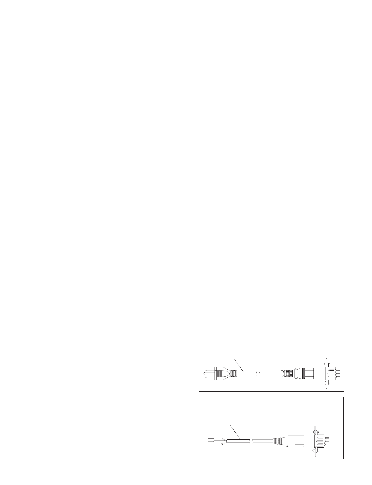
1-2-2. Power Cord
w
. Use the approved Power Cord (3-core mains lead)/Appli-
ance Connector/Plug with earthing-contacts that conforms to the safety regulations of each country if applicable.
. Use the Power Cord (3-core mains lead)/Appliance
Connector/Plug conforming to the proper ratings (Voltage, Ampere).
If you have questions on the use of the above Power Cord/
Appliance Connector/Plug, please contact your local Sony
Sales Office/Service Center.
c
. Never use an injured power cord.
. Plugging the power cord in the AC inlet, push as far as it
will go.
1-2. Power Supply
1-2-1. Power Specifications
A switching regulator is used for the power supply of this
unit. The voltage within the range of 100 V to 240 V can be
used without changing the supply voltage.
Power requirements: AC 100 to 240 V ?10 %
Power frequency: 50/60 Hz
Current consumption (when all options are installed) :
MVS-6520/6530/3000: 4.0 to 1.7 A
MVS-6520
For customers in the U.S.A. and Canada
1 Power cord, 125 V 10 A (2.4 m) : ! 1-551-812-31
1
For customers in the all European countries
1 Power cord, 250 V 10 A (2.5 m) : ! 1-782-929-12
1
AC inlet
AC inlet
1-1 (E)
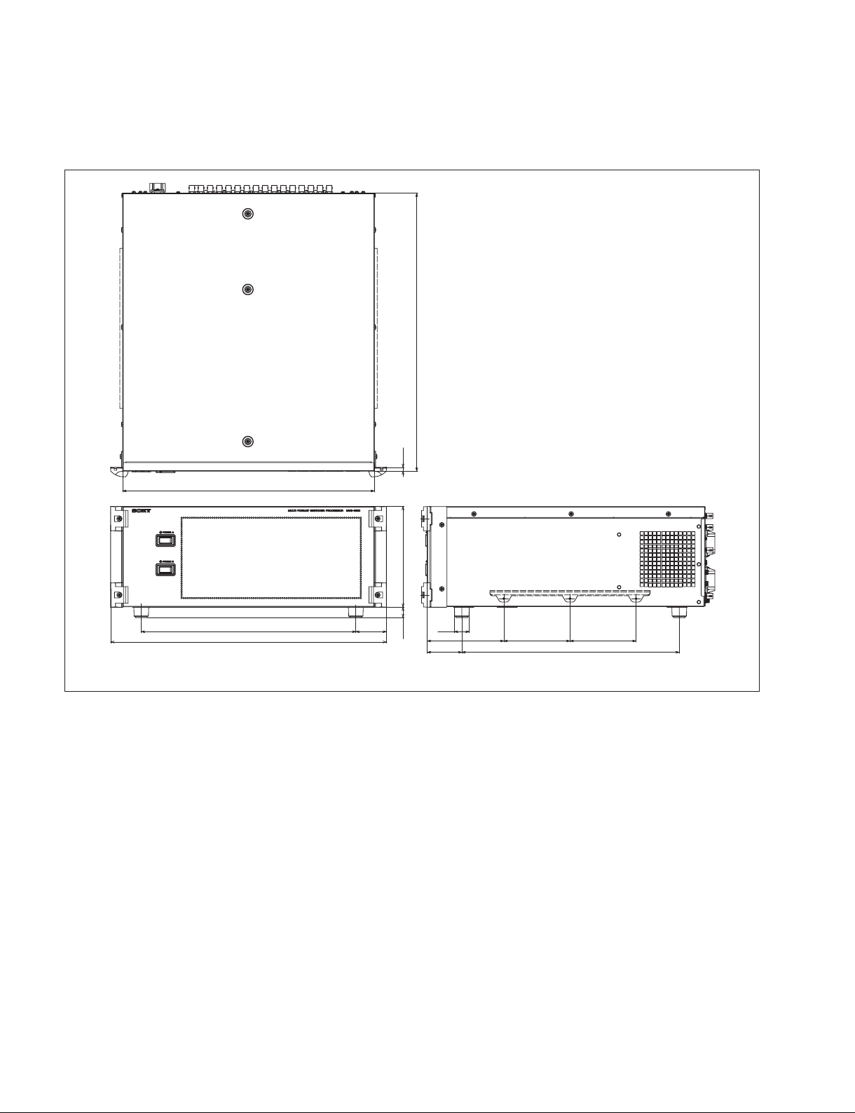
1-3. Installation Space (External Dimensions)
MVS-6520
485.7
440
375
482
53.5
176 (4U)18.2 6.5
Φ26
134
60.5 380
115 .5115.5
Unit: mm
1-2 (E)
MVS-6520
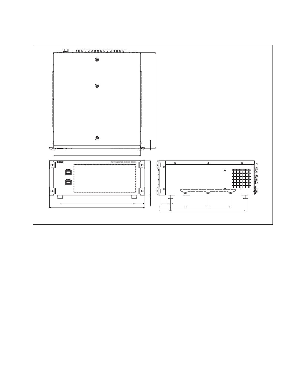
MVS-6530
485.7
6.5
440
375
482
53.5
176 (4U)18.2
Φ26
134
60.5 380
115.5115.5
Unit: mm
MVS-6520
1-3 (E)
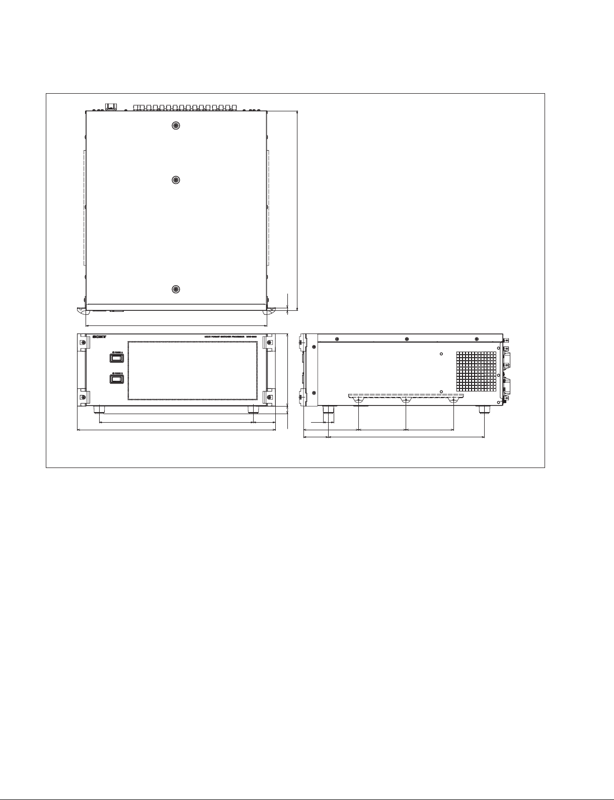
MVS-3000
485.7
440
375 53.5
482
176 (4U)18.2 6.5
Φ26
134
60.5 380
115.5115.5
Unit: mm
1-4 (E)
MVS-6520

1-4. Installing the Optional Board
Installation Procedure
The following options are available for the MVS-6520/6530/3000.
MVS-6520/6530 optional board list
Model name Board configuration
Plug-in board (Front)
MKS-6550 FC-114 board
Format Converter Board
MKS-6570 DVP-55 board
Digital Multi Effect Board
1. Turn off the main power of this unit and disconnect the
2. Loosen the four screws (with drop-safe) and remove
MVS-3000 optional board list
Model name Board configuration
Plug-in board (Front)
MKS-6550 FC-114 board
Format Converter Board
1-4-1. Installing the Plug-in Boards
c
Be sure to turn off the POWER switch before starting
installation work.
If installation work is started with the POWER switch left
on, it may cause electrical shock or damage to printed
circuit boards.
3. Remove the four fixing screws (B3 x 8) and remove
AC power cord from the wall outlet.
the front panel in the direction of the arrow.
Screws
(with drop-safe)
Front panel
Screws
(with drop-safe)
the Extract PWB stopper assembly.
In MVS-6520/6530/3000, the slot for installing each
plug-in board is specified. Install each board in the specified slot correctly according to the indications as described
in 1 and 2 below.
1 The board name is indicated close to the left-of-center
of each plug-in board.
2 The board name is indicated on the right surface of the
inside of front panel of MVS-6520/6530/3000.
m
. Check to see that connectors of the plug-in boards are
securely inserted into the mother board (MB-1196/1196A
board) without loose contact.
If any plug-in board is inserted into the incorrect slot, it
causes a system error and the system will not work
correctly.
. After installing the plug-in board, the software must be
installed. Install the software of V8.00 or later version.
For installing the software, refer to the User’s Guide of
the MVS-6520/6530/3000 system.
PSW
3 x 8
Extract PWB stopper
assembly
PSW3 x 8
MVS-6520
1-5 (E)
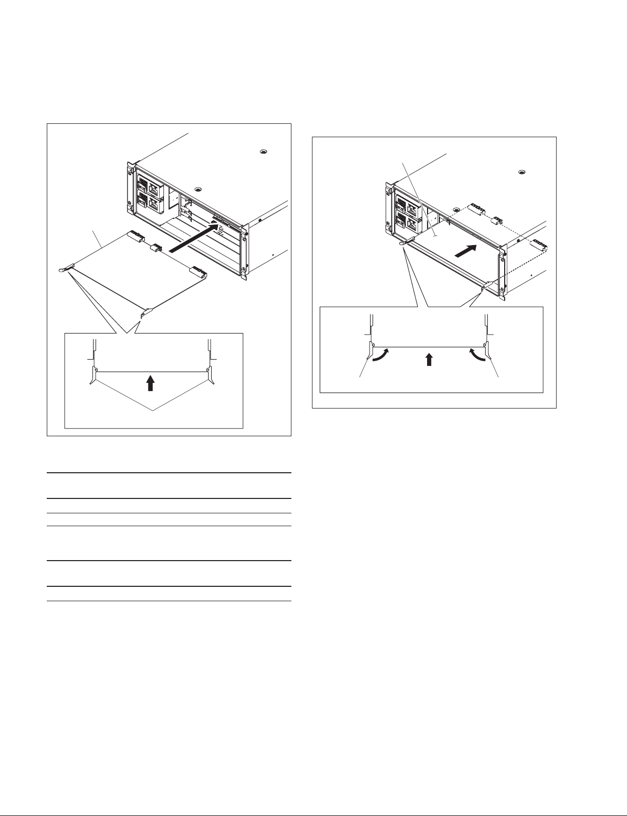
4. While the eject levers are opened as shown in the
illustration, insert the plug-in board into the board
guide rail.
Plug-in board
5. While closing the eject levers in the direction of arrow
1, push in the plug-in board.
6. Attach the extract PWB stopper assembly and the front
panel by reversing the installation steps of 2 and 3.
Plug-in board
11
Eject levers
MVS-6520/6530 option
Name of option Plug-in board Board name of the
front side
MKS-6570 DVP-55 board DVP
MKS-6550 FC-114 board FC
MVS-3000 option
Name of option Plug-in board Board name of the
front side
MKS-6550 FC-114 board FC
Eject lever
Eject lever
1-6 (E)
MVS-6520
1-5. Rack Mounting
2. Rack mounting procedure
The MVS-6520/6530/3000 is mounted in the 19-inch
standard rack. To mount the MVS-6520/6530/3000 in the
rack, use the specified rack mount kit and follow the
procedure described below.
. Specified rack mount kit : RMM-10
n
If other than the specified rack mount kit is used, the unit
may not be mounted in the 19-inch standard rack.
Parts of the RMM-10
. Rack bracket 2 pcs
. Right rack mount adapter 1 pc
. Left rack mount adapter 1 pc
.
Rack bracket attaching screw (B4 x 6: 7-682-560-09)
6 pcs
. Adapter attaching screw (B4 x 10: 7-682-562-09) 6 pcs
Other required parts
To mount in the rack, the rack mount kit RMM-10 and the
following part are required.
. Screw for rack mounting (B5 x 12 : 7-682-576-04) 4 pcs
1. Precautions for rack mounting
w
To prevent the rack from falling or moving, fix the rack on
.
a flat and steady floor and the like using bolts or others.
If the rack falls due to the weight of the equipment, it
may cause death or serious injury.
. Be sure to use the specified rack mount kit.
If not, injury may result and the equipment may fall due
to insufficient strength.
. After rack mounting, be sure to tighten the screws on the
rack angle and fix the unit in the rack.
If the screws on the rack angle are not tightened, the unit
may slip from the rack and fall, causing injury.
This section describes the rack mounting procedure using
the RMM-10 rack mount kit.
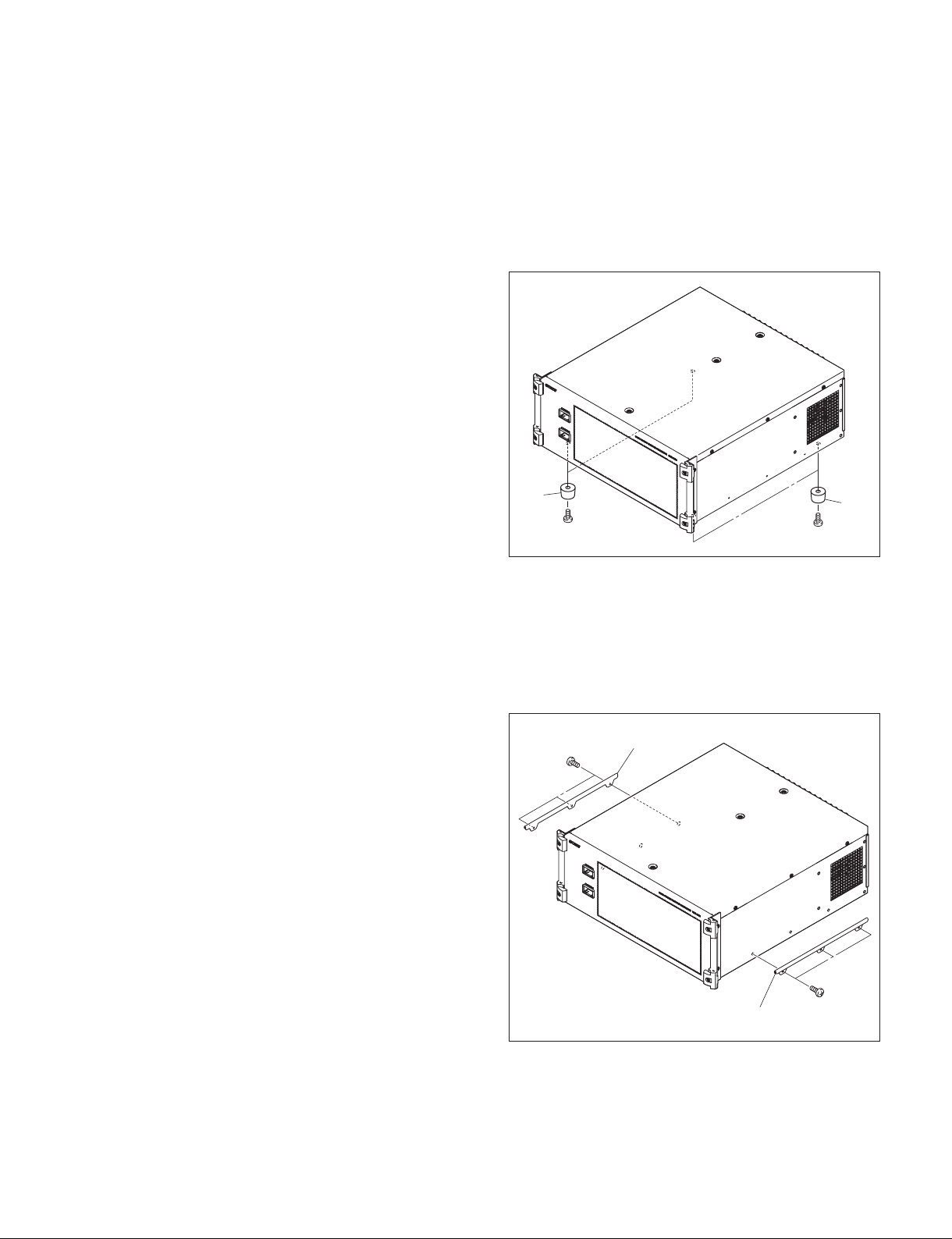
1. Loosen the four screws (B4 x 10) and remove the four
feet.
Feet
B4 x 10
B4 x 10
Feet
2. Attach the rack bracket to the side of the equipment
using the specified six screws.
n
Use B4 x 6 screws.
Tighten the screws to the following torque.
_2
Tightening torque: 120 x 10
B4 x 6
Rack bracket
N.m {12.2 kgf.cm}
c
When mounting the unit in the rack, note the following:
. Be sure to mount in the rack with two persons or more.
. Be careful not to catch your fingers or hands in the rack
mount rail or others.
. Mount in the rack in a stable position.
n
If several units are mounted in a rack, it is recommended to
install a ventilation fan to prevent temperature rise inside
the rack.
MVS-6520
Rack bracket
B4 x 6
1-7 (E)
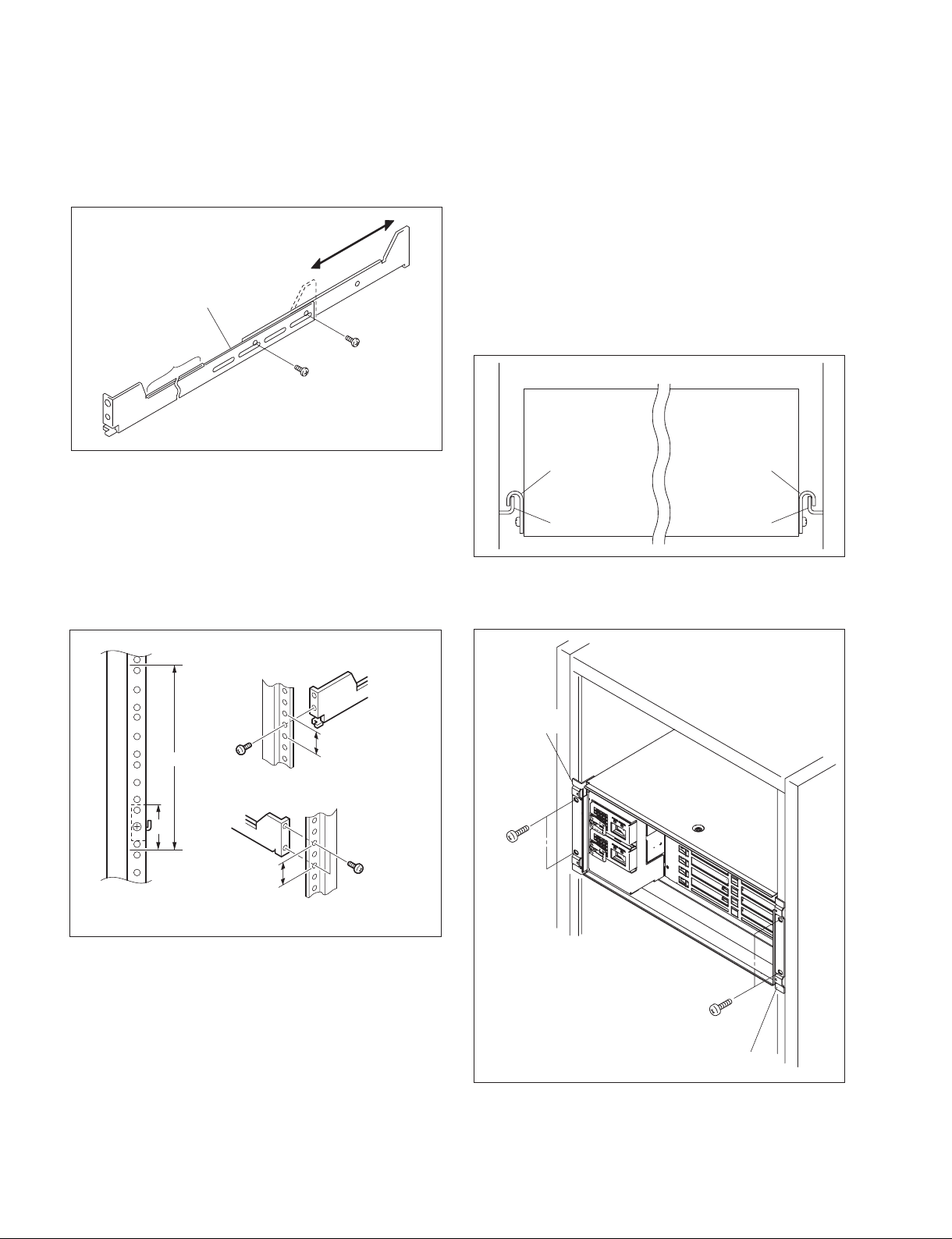
3. Loosen the screws on the rear of the right and left
adapters and adjust the length of the adapter according
to the depth of the rack.
(The illustration below shows the left adapter.)
Adapter
Portion of
the rail
B4 x 6
B4
x 6
n
Maximum depth of adapter: 750 mm
Minimum depth of adapter: 595 mm
4. Attach the right and left adapters to the rack completely using the specified six screws.
(The illustration below shows the left adapter.)
5. Tighten the screws (B4 x 6 : two screws each on the
right and left) for adjusting the length of the adapter
completely (the screws that were loosened in step 3).
6. Remove the front panel of the equipment.
(Refer to Section 1-4-1.)
7. Align the groove of the rack bracket at the side of the
equipment with the rail, and slide the equipment to the
rear.
n
The rack brackets are hooked on the rails as shown
below.
Rack bracket Rack bracket
Rail Rail
8. Fix the rack angle in the rack using the specified
screws.
1U
4U
B4
Rack angle
31.75
x
10
x
12
B5
B4
x
31.75
10
Unit: mm
B5x 12
Rack angle
9. Attach the front panel to this unit.
(Refer to Section 1-4-1.)
1-8 (E)
MVS-6520
 Loading...