

Page 1

Multi Format Switcher System
MFS-2000 System
(With MKS-2010/MKS-2015/MKS-2017 Control Panel)
User’s Guide [English]
1st Edition (Revised 1)
Software Version 2.00 and Later
Page 2

NOTICE TO USERS
® 2004 Sony Corporation. All rights reserved.
This manual or the software described herein, in whole or in
part, may not be reproduced, translated or reduced to any
machine readable form without prior written approval from
Sony Corporation.
SONY CORPORATION PROVIDES NO WARRANTY WITH
REGARD TO THIS MANUAL, THE SOFTWARE OR OTHER
INFORMATION CONTAINED HEREIN AND HEREBY
EXPRESSLY DISCLAIMS ANY IMPLIED WARRANTIES OF
MERCHANTABILITY OR FITNESS FOR ANY PARTICULAR
PURPOSE WITH REGARD TO THIS MANUAL, THE
SOFTWARE OR SUCH OTHER INFORMATION. IN NO
EVENT SHALL SONY CORPORATION BE LIABLE FOR
ANY INCIDENTAL, CONSEQUENTIAL OR SPECIAL
DAMAGES, WHETHER BASED ON TORT, CONTRACT, OR
OTHERWISE, ARISING OUT OF OR IN CONNECTION
WITH THIS MANUAL, THE SOFTWARE OR OTHER
INFORMATION CONTAINED HEREIN OR THE USE
THEREOF.
Sony Corporation reserves the right to make any modification
to this manual or the information contained herein at any time
without notice.
The software described herein may also be governed by the
terms of a separate user license agreement.
2
Page 3

Table of Contents
Chapter 1 Overview
Introduction .................................................7
System Features .........................................7
Options......................................................... 8
Chapter 2 Names and Functions of
Parts
Control Panel Types ...................................9
Control Panel Configuration .................... 11
M/E Cross-Point Control Block ..................12
PGM/PST Cross-Point Control Block.........14
AUX Bus Control Block ............................. 15
M/E Transition Control Block.....................16
PGM/PST Transition Control Block ...........17
M/E Key Transition Control Block............. 18
Downstream Key/Fade to Black Control
Block.......................................................18
Flexi Pad Control Block.............................. 19
Effect/Wipe Control Block..........................20
Utility Control Block................................... 22
Macro Control Block................................... 23
Menu Control Block....................................23
Power Indicators, “Memory Stick” Slot, USB
Connector................................................23
“Memory Sticks” .......................................24
Usable “Memory Sticks”............................. 24
Handling “Memory Sticks”......................... 24
Chapter 3 Using Menus
Accessing Menus...................................... 25
Accessing Menus From the Top Menu .......25
Accessing Menus by Double Clicking ........26
Accessing Menus by Single Clicking..........28
Interpreting Menu Screens....................... 29
Basic Screen ................................................29
Popup Windows ..........................................32
Basic Menu Operations ............................39
Selecting Menus ..........................................39
Selecting Functions ..................................... 40
Setting Parameters.......................................40
Exiting the Menu System.......................... 42
Chapter 4 Basics of Video Switching
Basic Operations (1): Video Switching on
the M/E Bank ......................................... 44
Basic Operations (2): Video Switching on
the PGM/PST Bank — For 1.5 M/E
Systems ................................................. 47
Chapter 5 Basic Operations
Selecting Video ......................................... 49
Flow of Operations......................................49
Selecting Video in the M/E Cross-Point
Control Block .........................................50
Selecting Video in the PGM/PST Cross-Point
Control Block .........................................51
Selecting Video in the AUX Bus Control
Block.......................................................51
Selecting Transition Types ......................53
Flow of Operations......................................53
Selecting the Transition Type and the Next
Transition................................................54
Selecting Effects ....................................... 56
Flow of Operations......................................56
Selecting Effects With the Flexi Pad Control
Block.......................................................57
Selecting Effects From Menus ....................58
Effect Types ................................................60
Selecting Channels ......................................61
Changing the Position and Size of Effect
Patterns .................................................63
Flow of Operations......................................63
Changing Pattern Position and Size With the
Joystick ...................................................64
Changing Pattern Size and Position From
Menus .....................................................64
Modifying Video Borders.......................... 66
Flow of Operations......................................66
Adding Borders to Video ............................67
Softening Video Edges (Soft Edge/Soft
Border)....................................................68
Preparing Transitions ............................... 69
Flow of Operations......................................69
Setting Transition Rates ..............................69
Selecting Effect Directions..........................71
Executing Transitions............................... 73
3Table of Contents
Page 4

Flow of Operations......................................73
Executing Transitions.................................. 73
Composing Video With Keys ................... 76
Flow of Operations......................................76
M/E Keys and Downstream Keys ...............77
Inserting Text With a Luminance Key or
Linear Key ..............................................77
Composing Video With Chroma Keys........81
Composing Video With Pattern Keys .........82
Adding Borders to Keys.............................. 83
Masking Part of a Key................................. 84
Moving a Key Over or Under .....................85
Inserting and Deleting Keys Only............... 86
Using Internally Generated Signals......... 88
Flow of Operations......................................88
Using a Color Background.......................... 88
Fading the Video to Black ........................93
Flow of Operations......................................93
Chapter 6 Advanced Operations
Advanced Effect Operations .................... 95
Transforming Effect Patterns ......................95
Cropping Effects .........................................97
Adding Beveled Edges to Video .................98
Adding Lighting ........................................100
Adding Afterimages (Trail)....................... 100
Adding Shadows Around Effects.............. 102
Composing a Video border Color From Two
Colors....................................................102
Using Pattern Specific Transformations ...103
Saving, Recalling, and Deleting Effect
Snapshots..............................................103
Advanced Key Operations .....................104
Processing Key Signals .............................104
Adjusting Key Borders..............................105
Adjusting Chroma Keys ............................106
Transforming the Pattern of a Pattern Key109
Setting Key Mask Shapes and Positions ... 109
Using the Show Key Function ..................110
Using Key Memory................................... 110
Color Correction...................................... 111
Selecting the Color Correction Signal....... 111
Output of Color Correction Results ..........111
Flow of Color Correction Operations........111
CCR Menu.................................................111
Input Video Processing .............................112
Primary Color Correction..........................113
Secondary Color Correction......................114
RGB Clip...................................................115
Luminance Processing...............................115
Spot Color Adjustment..............................117
Output Video Processing...........................118
YUV Clip ..................................................118
Frame Memory......................................... 119
Overview ...................................................119
Flow of Frame Memory Operations..........119
Preparations...............................................120
Selecting Input Signals for Frame Memory ....
120
Freezing Images and Saving Them to Memory
120
Recalling Freeze Images Saved in Frame
Memory ................................................122
Managing Image Files ...............................122
Snapshots................................................ 124
What are Snapshots? .................................124
Saving Snapshots.......................................125
Recalling Snapshots ..................................126
Deleting Snapshots ....................................126
Macros...................................................... 127
What Are Macros?.....................................127
Creating a New Macro ..............................127
Recalling a Macro Register and Executing a
Macro....................................................129
Editing a Macro .........................................131
Saving a Macro..........................................132
Deleting a Macro .......................................132
Using Macro Attachment ..........................132
Safe Title .................................................. 134
Copying.................................................... 135
Copy Operation Targets ............................135
Using Buttons to Copy Key Settings.........135
Chapter 7 File Operations
Overview .................................................. 137
Batch Operating on Data Files............... 137
Saving All Data at Once............................137
Loading All Data at Once..........................138
Deleting All Data at Once .........................138
Batch Operating on Data Files of Selected
Categories ........................................... 139
Saving the Data of Selected Categories ....139
Loading the Data of Selected Categories ..139
Deleting the Data of Selected Categories..140
Operating on Individual Data Files ........ 140
Loading Data Files ....................................140
4 Table of Contents
Page 5

Saving Data Files ......................................141
Deleting Data Files....................................142
Renaming Data Files .................................142
Copying Data Files....................................143
Common Operations – Selecting the Frame
Memory Category and the Target Media ...
144
Chapter 8 External Device
Operations
Control From Editing Systems ..............145
Overview ...................................................145
Controllable Functions ..............................145
Preparations............................................... 145
Controlling External Devices .................146
Overview ...................................................146
Manual VTR/Disk Recorder/Extended VTR
Operations.............................................146
Checking VTR, Disk Recorder, and Extended
VTR Information ..................................147
Disk Recorder/Extended VTR File Operations
149
Simple Connection to MKS-8080/8082 AUX
Bus Remote Panel ..............................151
Panel Maintenance (Panel Menu)..............164
System Adjustments (System Adjust Menu)...
165
System Reset and Memory Initialization
(Initialize Menu) ...................................165
Input Signal Setup (Input/Output Menu)...166
Output Signal Setup (Input/Output Menu) 167
Utility Settings (Utility Menu) ..................170
Key Setup (Key Menu)..............................173
Settings Relating to Video Switching
(Transition Menu).................................174
Macro Execution Mode Settings (Macro
Menu)....................................................175
GPI Input/Output Setup (GPI Menu) ........176
Tally Setup (System Tally Menu) .............182
External Device Connection Port Setup
(Device Menu)......................................187
Index......................................................... 193
Chapter 9 System Settings
Basic Settings .........................................153
Format Settings (Format Menu)................ 153
Setting the Startup Mode (Startup Mode
Menu)....................................................154
Output Signal Assignment (Output Assign
Menu)....................................................155
Assigning Signals to Cross-Point Buttons
(Operation Menu) .................................156
Saving Setup (Startup Mode Menu)..........160
Installing Software ..................................161
Displaying Version Information (Version
Information Menu) ...............................161
Displaying Detail Information (Detail
Information Menu) ...............................161
Manually Installing Software (Manual Install
Menu)....................................................161
Entering an Installation Key (License Menu) .
162
Other Settings .........................................164
Setting the Date and Time (Date/Time Menu)
164
5Table of Contents
Page 6

6 Table of Contents
Page 7
Overview
Chapter
Introduction
This manual is the User’s Guide for the MFS-2000 Multi
Format Switcher system.
The MFS-2000 system is comprised of the MFS-2000
Multi Format Switcher Processor, the main unit, and
optional system devices such as control panels and system
boards.
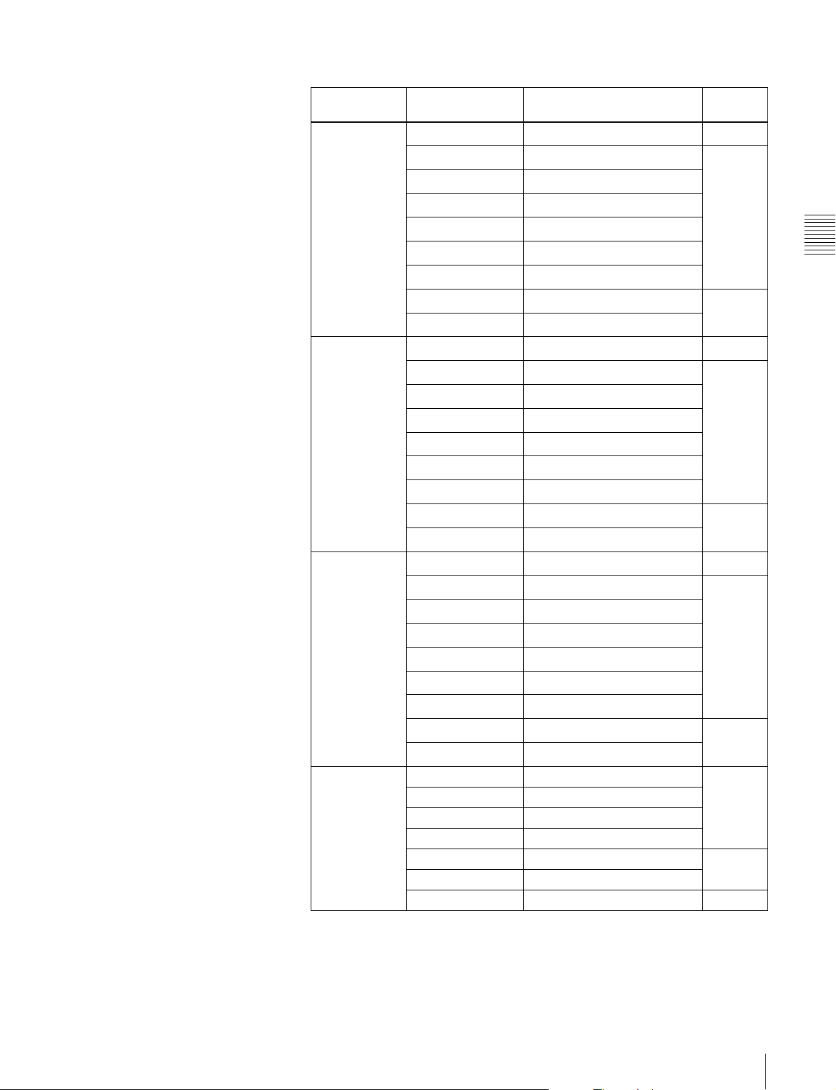
In place of the official device names, this manual refers to
the devices in the system by the names shown in the
following table.
Official device name Name used in this manual
MFS-2000 Multi Format
Switcher Processor
MKS-2010 1 M/E Control
Panel
MKS-2015 1.5 M/E Control
Panel
MKS-2017 1.5 M/E Wide
Control Panel
MKS-2470 DME Board Set DME or DME option
DCU-8000 Device Control Unit
(MKS-8700)
DCU-2000 Device Control Unit
(MKS-2700)
a) The term “1.5 M/E system” refers to systems using either the 1.5 M/E
panel or the 1.5 M/E wide panel.
Switcher or processor
Control panel or 1 M/E
panel
Control panel or 1.5 M/E
a)
panel
Control panel or 1.5 M/E
wide panel
DCU or MKS-8700
DCU or MKS-2700
a)
System Features
The MFS-2000 system is a compact multi-format switcher
system supporting numerous HD and SD signal formats.
The principal features of this system are as follows.
Multi-format support
Support for the 480i/59.94 and 576i/50 formats is standard.
The optional BZS-2000M Switcher Upgrade Software can
be installed to provide support for the following formats.
• 1080i/50, 59.94
• 1080PsF/23.976, 24, 25, 29.97
• 720p/59.94
State of the art special effects
In its standard configuration, the system supports a wide
variety of effect patterns, including advanced wipes.
Installation of the optional MKS-2470 DME Board Set
makes a further array of advanced effects available, such
as flip tumble, page turn, and 2ch P in P (two-channel
picture-in-picture).
Comprehensive keying capabilities
The system is equipped with two keyers and two
downstream keyers. All keyers support chroma keying and
special key transitions, independent of background
transitions (“independent key transitions”).
Optimal for use in live broadcast
environment
Compact and lightweight
Both control panels and processor are compact and
lightweight, designed for use where space is limited. This
is the optimal system for use in small-scale outdoor
broadcast vans and editing suites.
7 Introduction / System Features
Page 8

Outstanding ease of use
Buttons and other controls on the control panels are
Chapter 1 Overview
grouped in easy to understand functional blocks,
facilitating the quick decisions that must be made in a live
broadcast environment.
The menu control block features a 6.5-type color LCD
touch panel, for quick menu operation.
Options
The following options are available for the MFS-2000
system.
Selection of optimal control panel
Any of the following three control panels can be selected
for the optimal match to the intended applications and
working environment.
•MKS-2010
•MKS-2015
•MKS-2017
See page 10 for the principal differences between these
control panels.
• MKS-2010 1 M/E Control Panel
• MKS-2015 1.5 M/E Control Panel
• MKS-2017 1.5 M/E Wide Control Panel
• MKS-2110M Input/Output Connector Board
• MKS-2470 DME Board Set
• MKS-2440 Frame Memory Board Set
• MKS-2420M Color Corrector Board
• BZS-2000M Switcher Upgrade Software
• BZS-2470M DME Upgrade Software
• BZS-2440M Frame Memory Upgrade Software
• HK-PSU02 Power Supply Unit (for MFS-2000)
• HK-PSU11 Power Supply Unit (for control panels)
For more information about the above options, refer to the
MFS-2000-C Operation Manual supplied with the MFS2000 Multi Format Switcher Processor.
• MKS-2700 Device Control Unit
• MKS-8700 Device Control Unit
For more information about the above options, refer to the
DCU-2000 or DCU-8000 Operation Manual supplied
with the DCU-2000 or DCU-8000 Device Control Unit
Pack.
• MKS-2050 Editing Keyboard
• MKS-8050 Editing Keyboard
• BZS-8050 Editing Control Software
For more information about the above options, refer to the
MKS-2050/8050 Operation Manual supplied with the
MKS-2050/8050 Editing Keyboard and the BZS-8050
User’s Guide.
• MKS-8080 AUX Bus Remote Panel
• MKS-8082 AUX Bus Remote Panel
For more information about the above options, refer to the
MKS-8080/8082 Operation Guide or Operation Manual
supplied with the MKS-8080/8082 AUX Bus Remote
Panel.
Note that the MKS-8080/8082 Operation Manual is
supplied as a PDF file unlike the MKS-8080/8082
Operation Guide. For more information about the MKS8080/8082 Operation Manual, contact the Sony dealer
from whom you purchased the MKS-8080/8082.
8 Options
Page 9

Names and Functions of
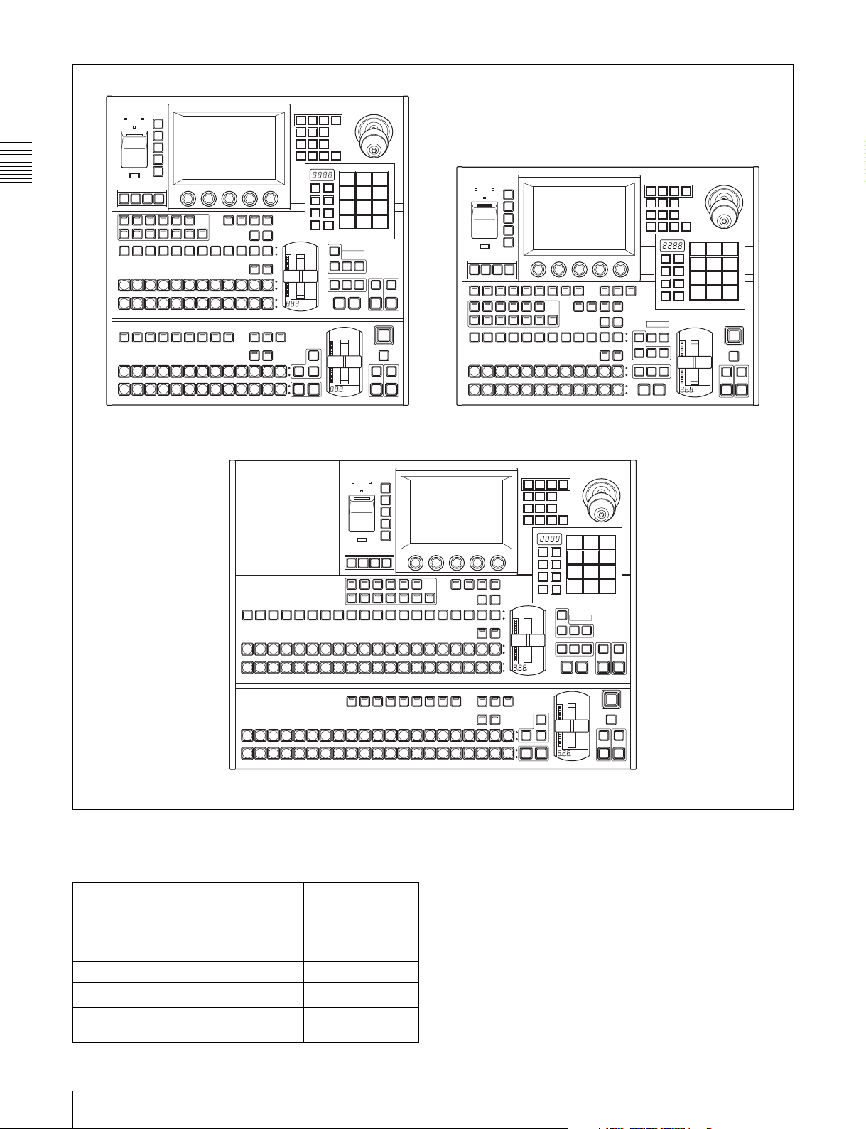
Control Panel Types
In this system, you can use any one of the three control
panels shown on the following page. This manual refers to
these control panels by the names shown in parentheses ( )
in the figure on that page.
Parts
Chapter
9Control Panel Types
Page 10
MENU
A POWER
B
TOP/
SHUT
DOWN
REG
FILE
SET
UP
DIAG
Chapter 2 Names and Functions of Parts
SAFE
EDIT
GPI
TITLE
AUX DELEGATION
AUX2 AUX3 AUX4
AUX1
KEY1
KEY2 DSK1 DSK2 CCR1 CCR2
AUX
BLACK
M/E
BLACK
A
BLACK
B
DEVICE/UTILITY
DEV1 JOGDEV2 PLAY STOP
PGM/PST
BLACK
PGM
BLACK
PST
EDIT
PVW
ALL
STOP
SRC
UTIL
FRAME
MEM
START
CUE
TC
XP/KY
KEY
BUS
HOLD
M/E PGM
XPT
HOLD
MACRO
PRE
SHTL
MCRO
XPT
HOLD
EFFECT
M/E
M/E
MENUP/P
1CH
2CH
TRAIL/
BVLD
LIGHT
SHDW
EDGE
BORD SOFT CROP
N/R REV POS
CTR
7 8 9
EFF/
M/E
WIPE
5 6
4
SNAP
PP/
SHOT
ALL
1 2 3
STORE
FRAMES
TRANSITION TYPE
MCRO
BANK
TRANS
SEL
RATE
KEY
PRIOR
BKGD KEY1 KEY2
NEXT TRANSITION
MIX EFF
TRANSITION TYPE
PST
COLOR
MIX
WIPE
MIX
AUTO
CUT
TRANS
FRAMES
SHIFT
COLOR
BKGD
SHIFT
COLOR
BKGD
COLOR
BKGD
POST
ATTCH
MCRO
ENBL
SHIFT
COLOR
M/E
BKGD
COLOR
M/E
BKGD
AUTO
TRANS
10
OVER OV ER
EFF
AUTO
DISS
TRNS
PST
KEY1
KEY2
COLOR
ON
ON
MIX
AUTO
AUTO
CUT
TRANS
TRANS
KEY2
KEY1
FTB
DSK
PVW
DSK2
DSK1
ON
ON
AUTO
AUTO
TRANS
TRANS
DSK1 DSK2
A POWER
B
SAFE
EDIT
GPI
TITLE
DEVICE/UTILITY
DEV1 JOGDEV2 PLAY STOP
AUX DELEGATION
AUX2 AUX3 AUX4
AUX1
KEY1
KEY2 DSK1 DSK2 CCR1 CCR2
AUX
BLACK
M/E
BLACK
A
BLACK
B
MENU
TOP/
SHUT
DOWN
REG
FILE
SET
UP
DIAG
START
ALL
CUE
TC
STOP
EDIT
UTIL
PVW
FRAME
MEM
MACRO
PRE
SHTL
MCRO
SRC
XP/KY
KEY
BUS
HOLD
M/E PGM
XPT
HOLD
EFFECT
M/E
M/E
MENU
1CH
2CH
TRAIL/
BVLD
LIGHT
SHDW
EDGE
BORD SOFT CROP
N/R REV POS
CTR
7 8 9
EFF
M/E
ALL
ATTCH
ENBL
KEY
PRIOR
BKGD KEY1 KEY2
NEXT TRANSITION
MIX EFF
TRANSITION TYPE
AUTO
TRANS
OVER OV ER
KEY1
ON
STORE
BANK
SEL
KEY2
ON
PST
COLOR
MIX
CUT
POST
MCRO
SHIFT
COLOR
BKGD
SHIFT
COLOR
BKGD
COLOR
BKGD
SNAP
SHOT
MCRO
TRANS
RATE
FRAMES
5 6
4
1 2 3
AUTO
10
TRNS
EFF
DISS
FTB
DSK
PVW
DSK1
ON
AUTO
TRANS
DSK1 DSK2
DSK2
ON
AUTO
TRANS
MKS-2015 Control Panel (1.5 M/E panel) MKS-2010 Control Panel (1 M/E panel)
MENU
APOWER
B
TOP/
SHUT
DOWN
REG
FILE
SET
UP
DIAG
SAFE
EDIT GPI
TITLE
AUX
BLACK
M/E
BLACK
A
BLACK
B
PGM/PST
BLACK
PGM
BLACK
PST
AUX DELEGATION
AUX1
KEY1
DEVICE/UTILITY
DEV1 JOGDEV2 PLAY STOP
EDIT
AUX2 AUX3 AUX4
PVW
KEY2 DSK1 DSK2 CCR1 CCR2
ALL
STOP
MKS-2017 Wide Control Panel (1.5 M/E wide panel)
Principal differences
The principal differences between the three control panels
are as follows.
Control panel PGM/PST cross-
point control
block, PGM/PST
transition control
block
1 M/E panel No 12 per row
1.5 M/E panel Yes
1.5 M/E wide
Ye s
panel
Number of crosspoint buttons
12 per row
20 per row
a)
a)
EFFECT
M/E
M/E
MENUP/P
1CH
2CH
TRAIL/
BVLD
LIGHT
SHDW
EDGE
BORD SOFT CROP
N/R REV POS
CTR
7 8 9
EFF
M/E
/WIPE
5 6
4
SNAP
PP/
SHOT
ALL
1 2 3
STORE
FRAMES
TRANSITION TYPE
MCRO
BANK
TRANS
SEL
RATE
KEY
PRIOR
BKGD KEY1 KEY2
NEXT TRANSITION
MIX EFF
PST
COLOR
MIX
WIPE
MIX
AUTO
CUT
TRANS
FRAMES
10
OVER OV ER
TRANSITION TYPE
AUTO
TRANS
EFF
AUTO
DISS
TRNS
PST
KEY1
KEY2
COLOR
ON
ON
MIX
AUTO
AUTO
CUT
TRANS
TRANS
KEY1
KEY2
FTB
DSK
PVW
DSK2
DSK1
ON
ON
AUTO
AUTO
TRANS
TRANS
DSK1 DSK2
SRC
UTIL
FRAME
MEM
START
CUE
TC
XP/KY
KEY
SHIFT
BUS
HOLD
M/E PGM
COLOR
BKGD
XPT
SHIFT
HOLD
COLOR
BKGD
COLOR
BKGD
MACRO
PRE
POST
SHTL
ATTCH
MCRO
MCRO
ENBL
XPT
SHIFT
HOLD
COLOR
M/E
BKGD
COLOR
M/E
BKGD
b) The 1.5 M/E panel and the 1.5 M/E wide panel differ in the number of
cross-point buttons. They are identical in all other respects.
Operation button positions
The positions of some operation buttons on the 1 M/E
panel are different from the positions of the buttons with
the same functions on the 1.5 M/E panel and 1.5 M/E wide
panel. This manual explains how to operate using the 1.5
M/E panel, but figures are also provided for the 1 M/E
panel when the buttons employed are in different
positions.
10 Control Panel Types
Page 11
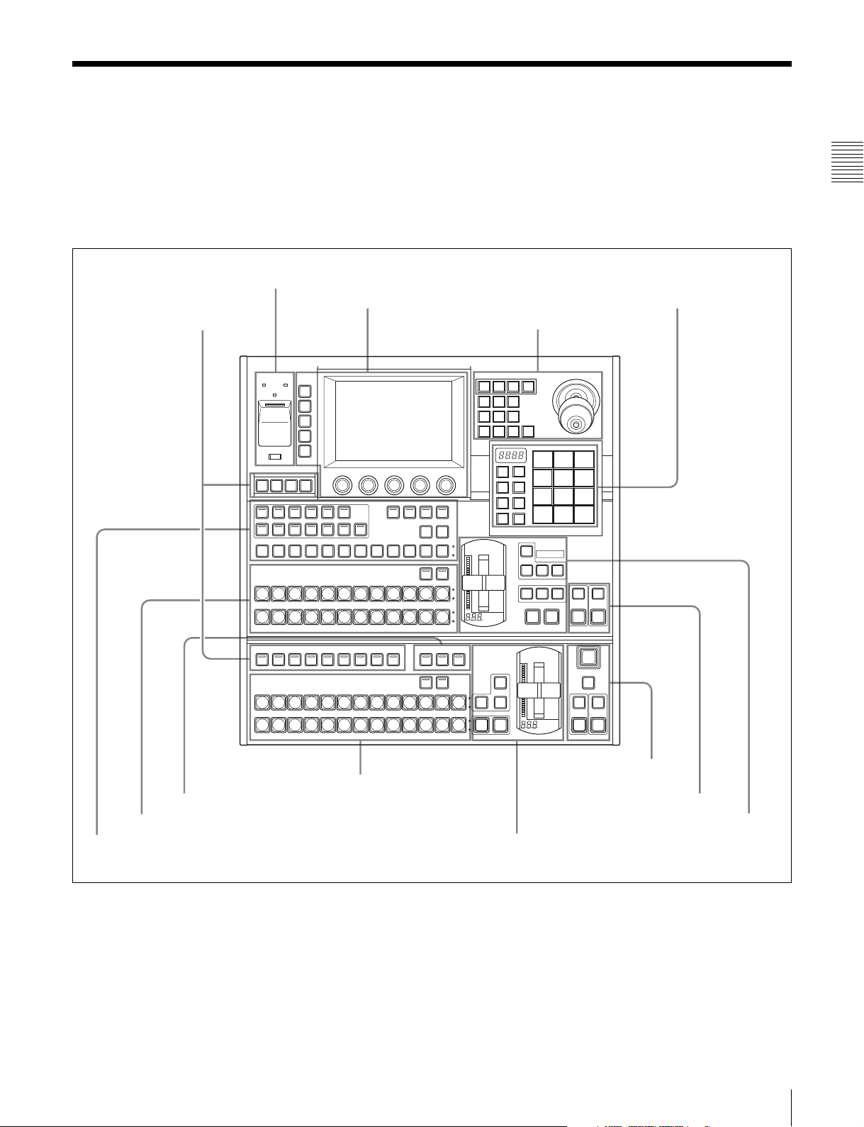
Control Panel Configuration
1.5 M/E panel and 1.5 M/E wide panel
The sole difference between these control panels is the
number of cross-point buttons per row. Most of the
illustrations in this manual show the configuration of the
1.5 M/E panel.
Power Indicators, “Memory Stick” Slot, USB Connector (page 23)
Menu Control Block (page 23)
Utility Control Block (page 22)
See the pages in parentheses ( ) for the functions of the
illustrated parts.
Flexi Pad Control Block (page 19)
Effect/Wipe Control Block (page 20)
Chapter 2 Names and Functions of Parts
Macro Control Block (page 23)
M/E Cross-Point Control Block (page 12)
AUX Bus Control Block (page 15)
MENU
A POWER
B
TOP/
SHUT
DOWN
REG
FILE
SET
UP
DIAG
SAFE
EDIT
GPI
TITLE
AUX DELEGATION
AUX2 AUX3 AUX4
AUX1
KEY1
KEY2 DSK1 DSK2 CCR1 CCR2
AUX
BLACK
M/E
BLACK
A
BLACK
B
DEVICE/UTILITY
DEV1 JOGDEV2 PLAY STOP
PGM/PST
BLACK
PGM
BLACK
PST
EDIT
UTIL
PVW
ALL
CUE
STOP
SRC
XP/KY
KEY
HOLD
M/E PGM
XPT
HOLD
MACRO
PRE
MCRO
XPT
HOLD
COLOR
COLOR
BKGD
COLOR
BKGD
MCRO
COLOR
BKGD
COLOR
BKGD
SHIFT
BKGD
SHIFT
FRAMES
POST
ATTCH
ENBL
SHIFT
M/E
TRANSITION TYPE
M/E
TRANS
BUS
FRAME
MEM
START
SHTL
TC
PGM/PST Cross-Point Control Block (page 14)
PGM/PST Transition Control Block (page 17)
EFFECT
M/E
M/E
1CH
2CH
BVLD
LIGHT
EDGE
BORD SOFT CROP
N/R REV POS
M/E
PP/
ALL
STORE
BANK
SEL
PST
COLOR
MIX
WIPE
MIX
AUTO
CUT
MENUP/P
TRAIL/
SHDW
CTR
7 8 9
EFF/
WIPE
SNAP
SHOT
MCRO
TRANS
RATE
4
1 2 3
10
KEY
PRIOR
OVER OVER
BKGD KEY1 KEY2
NEXT TRANSITION
MIX EFF
TRANSITION TYPE
AUTO
TRANS
FRAMES
5 6
EFF
AUTO
DISS
TRNS
PST
KEY1
KEY2
COLOR
ON
ON
MIX
AUTO
TRANS
KEY1
FTB
DSK
PVW
DSK1
ON
AUTO
TRANS
DSK1 DSK2
AUTO
TRANS
KEY2
DSK2
ON
AUTO
TRANS
CUT
Downstream Key/Fade to
Black Control Block (page 18)
M/E Key Transition Control Block (page 18)
M/E Transition Control Block (page 16)
11Control Panel Configuration
Page 12
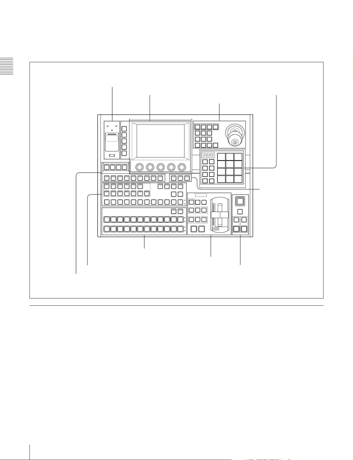
1 M/E panel
See the pages in parentheses ( ) for the functions of the
illustrated parts.
Chapter 2 Names and Functions of Parts
Power Indicators, “Memory Stick” Slot, USB Connector (page 23)
Menu Control Block (page 23)
Flexi Pad Control Block (page 19)
Effect/Wipe Control Block (page 20)
MCRO
COLOR
COLOR
BKGD
COLOR
BKGD
POST
SHIFT
BKGD
SHIFT
ATTCH
ENBL
KEY
PRIOR
BKGD KEY1 KEY2
NEXT TRANSITION
MIX EFF
TRANSITION TYPE
EFFECT
M/E
1CH
BVLD
EDGE
BORD SOFT CROP
N/R REV POS
OVER OVER
KEY1
ON
AUTO
TRANS
M/E
MENU
2CH
TRAIL/
LIGHT
SHDW
CTR
7 8 9
EFF
M/E
4 5 6
SNAP
ALL
SHOT
STORE
1 2 3
MCRO
BANK
TRANS
SEL
RATE
EFF
AUTO
10
DISS
TRNS
Macro Control
Block (page 23)
KEY2
ON
PST
COLOR
MIX
CUT
FRAMES
FTB
DSK
PVW
DSK1
ON
AUTO
TRANS
DSK1 DSK2
DSK2
ON
AUTO
TRANS
A POWER
B
SAFE
EDIT
GPI
TITLE
DEVICE/UTILITY
DEV1 JOGDEV2 PLAY STOP
AUX DELEGATION
AUX2 AUX3 AUX4
AUX1
KEY1
KEY2 DSK1 DSK2 CCR1 CCR2
AUX
BLACK
M/E
BLACK
A
BLACK
B
MENU
TOP/
SHUT
DOWN
REG
FILE
SET
UP
DIAG
ALL
START
CUE
STOP
EDIT
PVW
SHTL
TC
UTIL
FRAME
MEM
MACRO
PRE
MCRO
SRC
XP/KY
KEY
BUS
HOLD
M/E PGM
XPT
HOLD
M/E Cross-Point Control Block (page 12)
M/E Transition Control Block (page 16)
AUX Bus Control Block (page 15)
Utility Control Block (page 22)
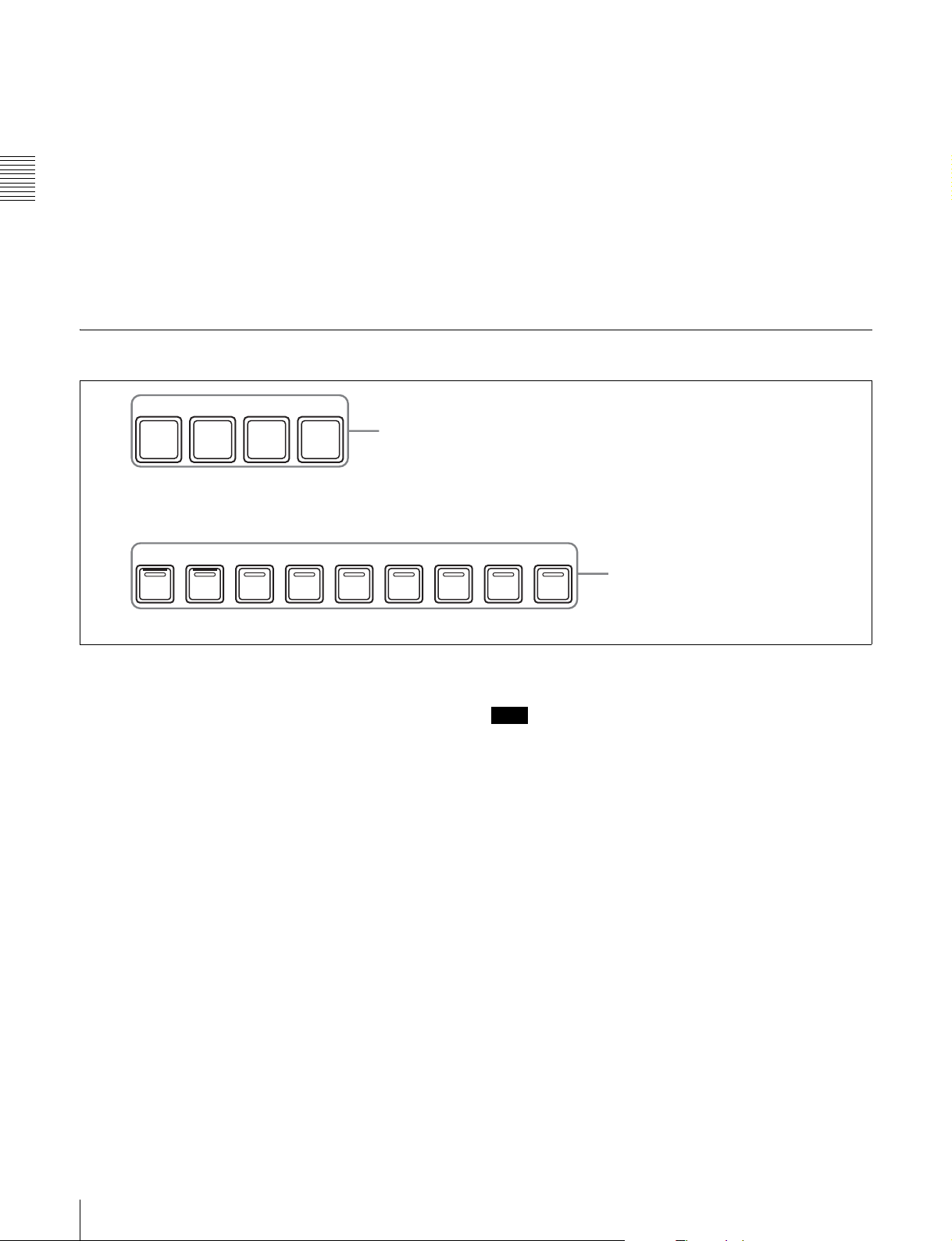
M/E Cross-Point Control Block
Use the M/E (mix/effect) cross-point control block to
select the video signals to be used as the video background.
Downstream Key/Fade to Black Control Block (page 18)
12 Control Panel Configuration
Page 13
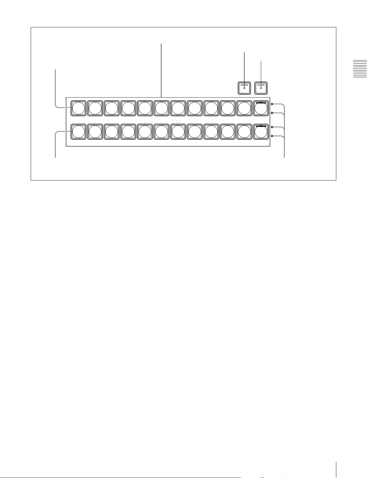
Background A row
1 Cross-point button rows
2 XPT HOLD button
3 SHIFT button
M/E
BLACK
A
BLACK
B
Background B row
a Cross-point button rows
Select background video by pressing the corresponding
button.
The buttons in the background A row select the
background video which is output before the start of a
transition (A bus video). Pressing a button selects the
signal assigned to that button (input signals to the IN1 to
IN16 connectors
1)
of the processor, or signals which the
processor generates internally). The button lights in red
(high tally) if the selected signal is being output to the
program video (final output video). Otherwise it lights in
amber (low tally).
1) The MKS-2110M Input/Output Connector Board must be installed to use
the IN9 to IN16 connectors.
The buttons in the background B row select the
background video which is output after a transition (B bus
video). The button lights in red (high tally) if the selected
signal is being output to the program video. It lights in
amber (low tally) if the selected signal is not being output
to the program video.
In addition to the operating mode described above (flipflop mode), you can also select bus fixed mode. In bus
fixed mode, the signal selected on the background A row
is always output when the fader lever is at the top, and the
signal selected on the background B row is always output
when the fader lever is at the bottom.
XPT
SHIFT
HOLD
COLOR
BKGD
COLOR
BKGD
4 Tally indicators
selects the same signal as the fifth button from left in the B
row.
You can use the Xpt Assign menu to freely change the
assignment of signals to cross-point buttons.
For details, see “Assigning Signals to Cross-Point Buttons
(Operation Menu)” (page 156).
Cross-point button numbers
On the 1 M/E panel and the 1.5 M/E panel, there are 12
cross-point buttons in each row. On the 1.5 M/E wide
panel, there are 20 cross-point buttons in each row. These
buttons are numbered 1 to 12 or 1 to 20 from the left side
of the panel. Pressing the [SHIFT] button 3 to turn the
shift function on makes more cross-point button numbers
available: numbers 13 to 24, or 21 to 40. This manual
refers to the buttons available when the shift function is on
as “shift side buttons,” and to the buttons available when
the shift function is off as “non-shift side buttons.”
See page 156 for more information about cross-point
button numbers.
b XPT (cross-point) HOLD button
By pressing this button to turn it on (it lights in amber), you
can recall a snapshot while retaining the current crosspoint button selection state. (The cross-point selection
information in the snapshot is ignored.)
Chapter 2 Names and Functions of Parts
For more information about bus fixed mode, see “Setting
the Bus Toggle On or Off” (page 174).
The buttons in the A row and the B row select the same
signals. For example, the fifth button from left in the A row
c SHIFT button
Press this button, turning it on, to use the cross-point
buttons as shift side buttons. Press it again, turning it off,
to use the cross-point buttons as non-shift side buttons.
13Control Panel Configuration
Page 14
Note
This button does not light and does not function when you
are using the rightmost buttons in the cross-point button
rows (the 12th or 20th buttons) as [SHIFT] button.
For more information about operations to use the
rightmost buttons as [SHIFT] buttons, see “To use the
rightmost buttons in cross-point button rows as [SHIFT]
buttons (shift mode selection)” (page 158).
d Tally indicators
Currently not used.
Chapter 2 Names and Functions of Parts
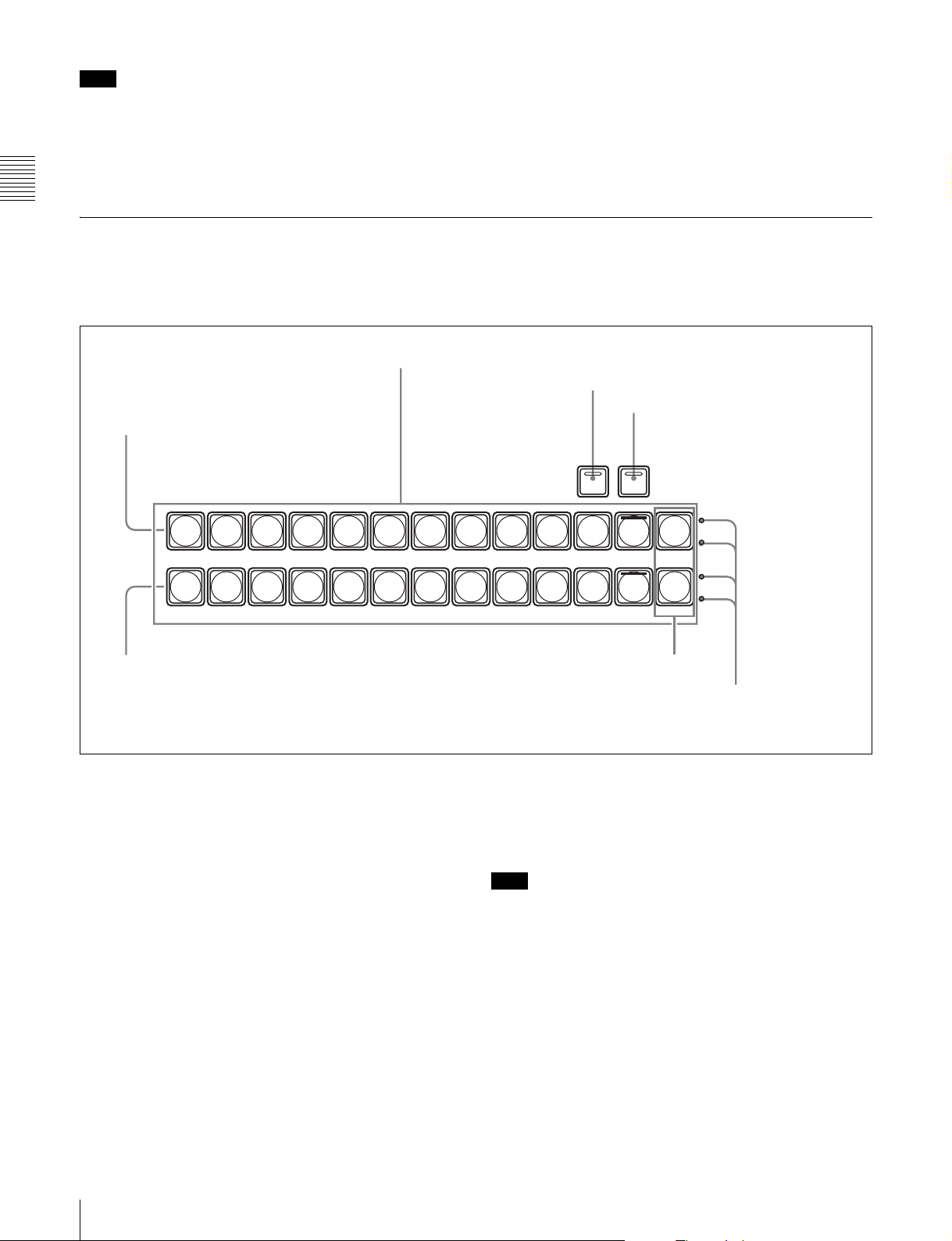
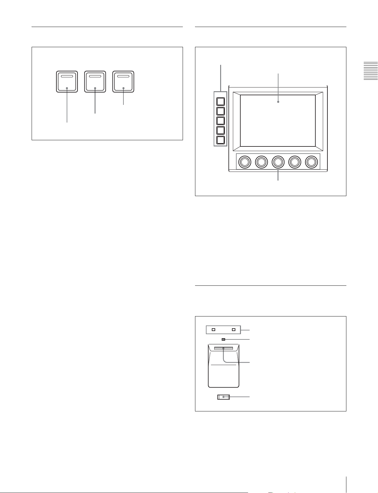
PGM/PST Cross-Point Control Block
Use the PGM/PST (program/preset) cross-point control
block to select the video signals to be used as the
background in program video (final output video).
1 Cross-point button rows
PGM row
PGM/PST
BLACK
PGM
BLACK
PST
PST row
This control block is found only on the 1.5 M/E and 1.5 M/
E wide panels.
2 XPT HOLD button
3 SHIFT button
XPT
SHIFT
HOLD
COLOR
M/E
BKGD
COLOR
M/E
BKGD
M/E buttons
4 Tally indicator
a Cross-point button rows
The buttons in the PGM (program) row select the
background video which is output before the start of a
transition. The buttons in the PST (preset) row select the
background video after the end of a transition.
The signals selectable with the cross-point buttons are the
same as the signals selectable with the corresponding
buttons in the M/E cross-point control block (see page 12).
The meaning of the colors in which buttons light and
button numbers are also the same. The [M/E] buttons at the
right edge of each cross-point button row are reentry
buttons. They allow you to import video created in the M/
E block and use it as background video in the PGM/PST
block.
b XPT (cross-point) HOLD button
By pressing this button to turn it on (it lights in amber), you
can recall a snapshot while retaining the current crosspoint button selection state. (The cross-point selection
information in the snapshot is ignored.)
14 Control Panel Configuration
c SHIFT button
Press this button, turning it on, to use the cross-point
buttons as shift side buttons. Press it again, turning it off,
to use the cross-point buttons as non-shift side buttons
Note
This button does not light and does not function when you
are using the rightmost buttons in the cross-point button
rows (the 12th or 20th buttons) as [SHIFT] button.
For more information about operations to use the
rightmost buttons as [SHIFT] buttons, see “To use the
rightmost buttons in cross-point button rows as [SHIFT]
buttons (shift mode selection)” (page 158).
d Tally indicator
Currently not used.
Page 15
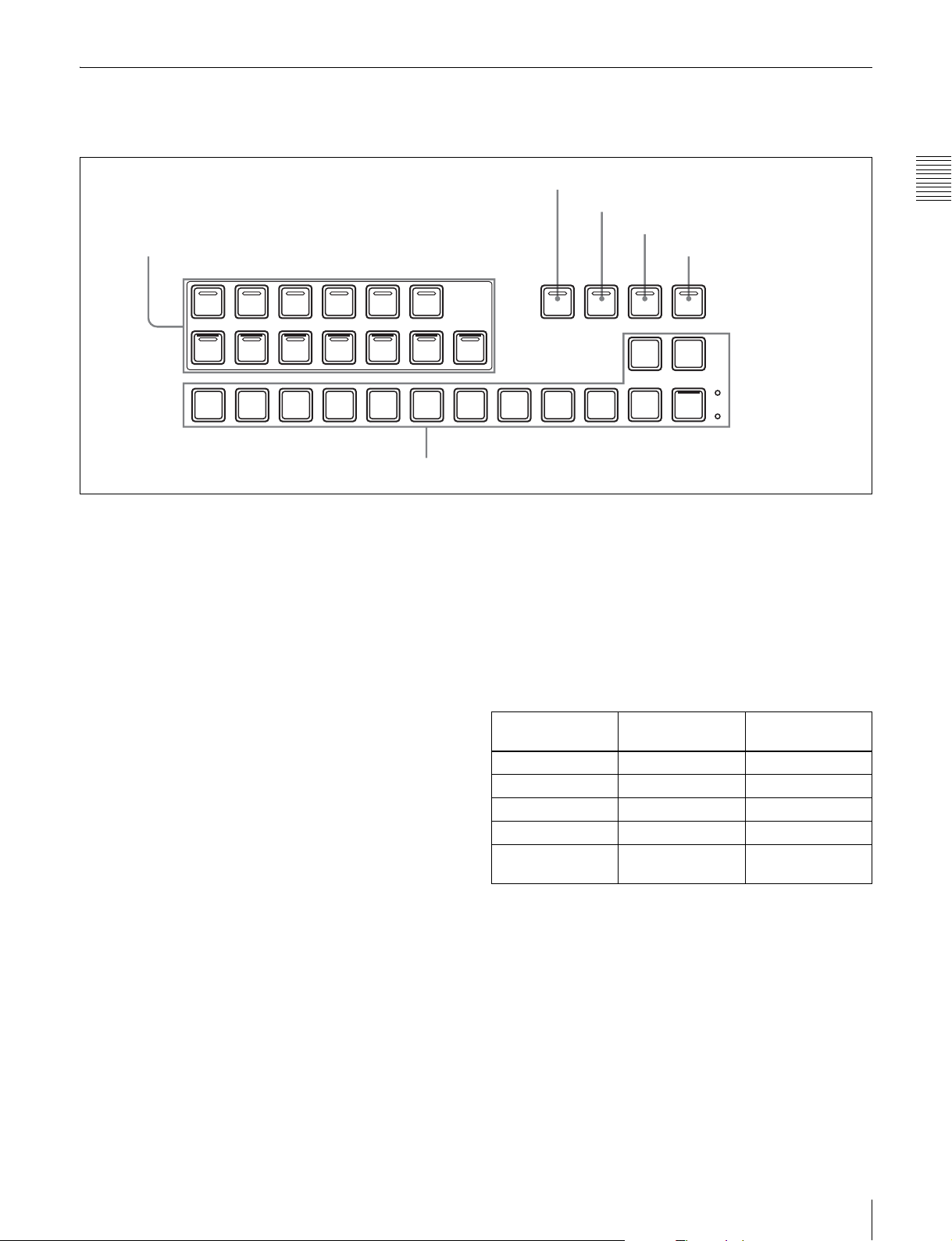
AUX Bus Control Block
Use this block to select key signals and to select the signals
to which a variety of functions are applied.
1 AUX delegation buttons
AUX DELEGATION
EDIT
AUX2 AUX3 AUX4
AUX1
PVW
UTIL
2 SRC BUS button
3 KEY button
4 XP/KY HOLD button
SRC
BUS
KEY
XP/KY
HOLD
Chapter 2 Names and Functions of Parts
5 SHIFT button
SHIFT
KEY1
KEY2 DSK1 DSK2 CCR1 CCR2
AUX
BLACK
6 Cross-point button row
a AUX delegation buttons
By pressing one of the following buttons, lighting it, you
select the bus to which the cross-point button row 6 is
assigned. Signals selected in the cross-point button row are
output to the bus selected here.
The buses selectable by the various buttons are as follows.
AUX1 to 4: AUX1 to AUX4 buses
EDIT PVW: EDIT PVW (edit preview) bus
UTIL: Utility bus
KEY1: Key1 bus or Key1 Source bus. (The state of the
[SRC BUS] button 2 determines which of the two
buses is selected.)
KEY2: Key2 bus or Key2 Source bus. (The state of the
[SRC BUS] button 2 determines which of the two
buses is selected.)
DSK1: DSK1 (downstream key 1) bus or DSK1 Source
(downstream key 1 source) bus. (The state of the
[SRC BUS] button 2 determines which of the two
buses is selected.)
DSK2: DSK2 (downstream key 2) bus or DSK2 Source
(downstream key 2 source) bus. (The state of the
[SRC BUS] button 2 determines which of the two
buses is selected.)
CCR1 and CCR2: CCR1 (color correction 1) or CCR2
bus
FRAME MEM: Frame Memory Video bus, or Frame
Memory Key bus. (The state of the [SRC BUS] button
2 determines which of the two buses is selected.)
FRAME
MEM
M/E PGM
COLOR
BKGD
Buttons which target two buses ([KEY1], [KEY2],
[DSK1], [DSK2], and [FRAME MEM]) light in red if
signals on either of the buses are being output to program
video.
b SRC (source) BUS button
When an AUX delegation button which targets two buses
([KEY1], [KEY2], [DSK1], [DSK2], and [FRAME
MEM]) is turned on, the bus which is actually selected is
determined by whether this button is on (lit) or off (not lit).
AUX delegation
button
KEY1 Key1 bus Key1 Source bus
KEY2 Key2 bus Key2 Source bus
DSK1 DSK1 bus DSK1 Source bus
DSK2 DSK2 bus DSK2 Source bus
FRAME MEM Frame Memory
SRC BUS button
off
Video bus
SRC BUS button
on
Frame Memory
Key bus
c KEY button
In the following cases, you can select the key signal in the
cross-point button row by pressing this button to turn it on.
• When the AUX delegation button [AUX1], [AUX2],
[AUX3] or [AUX4] is lit.
• When the AUX delegation button [KEY1], [KEY2],
[DSK1], [DSK2], or [FRAME MEM] is lit with the
[SRS BUS] button being on.
The button lights in red (high tally) if signals on the
selected bus are being output to the program video (final
output video). Otherwise it lights in amber (low tally).
d XP/KY (cross-point/key) HOLD button
By pressing this button to turn it on (it lights in amber), you
can recall a snapshot while retaining the current crosspoint selection state (cross-point hold), for buses other
15Control Panel Configuration
Page 16
than key buses. For key buses, you can select any of the
following three options as the operating mode when a
snapshot is recalled with this button on.
• Cross-point hold (retain the current cross-point selection
state)
• Key disable (retain the current key settings)
• Key disable, plus retention of the current key on/off
Chapter 2 Names and Functions of Parts
states
See “Setting the key bus cross-point hold mode” (page
173) for more information about how to set the operating
mode.
f Cross-point button row
These buttons select the signals to be output to the bus
selected with the AUX delegation buttons.
The signals which can be selected with each cross-point
button are the same as the signals selected by the
corresponding buttons in the M/E cross-point control
block (see page 12). Button numbers and the meaning of
the colors in which the buttons light are the same as those
of the buttons in the M/E cross-point control block.
However, the cross-point button row in the AUX bus
control block contains an [M/E] button and a [PGM]
button, which are not present in the M/E cross-point button
rows. The [M/E] button selects the M/E program video,
e SHIFT button
Press this button, turning it on, to use the cross-point
and the [PGM] button selects the program video (final
output video).
buttons as shift side buttons. Press this button again,
turning it off, to use the cross-point buttons as non-shift
side buttons.
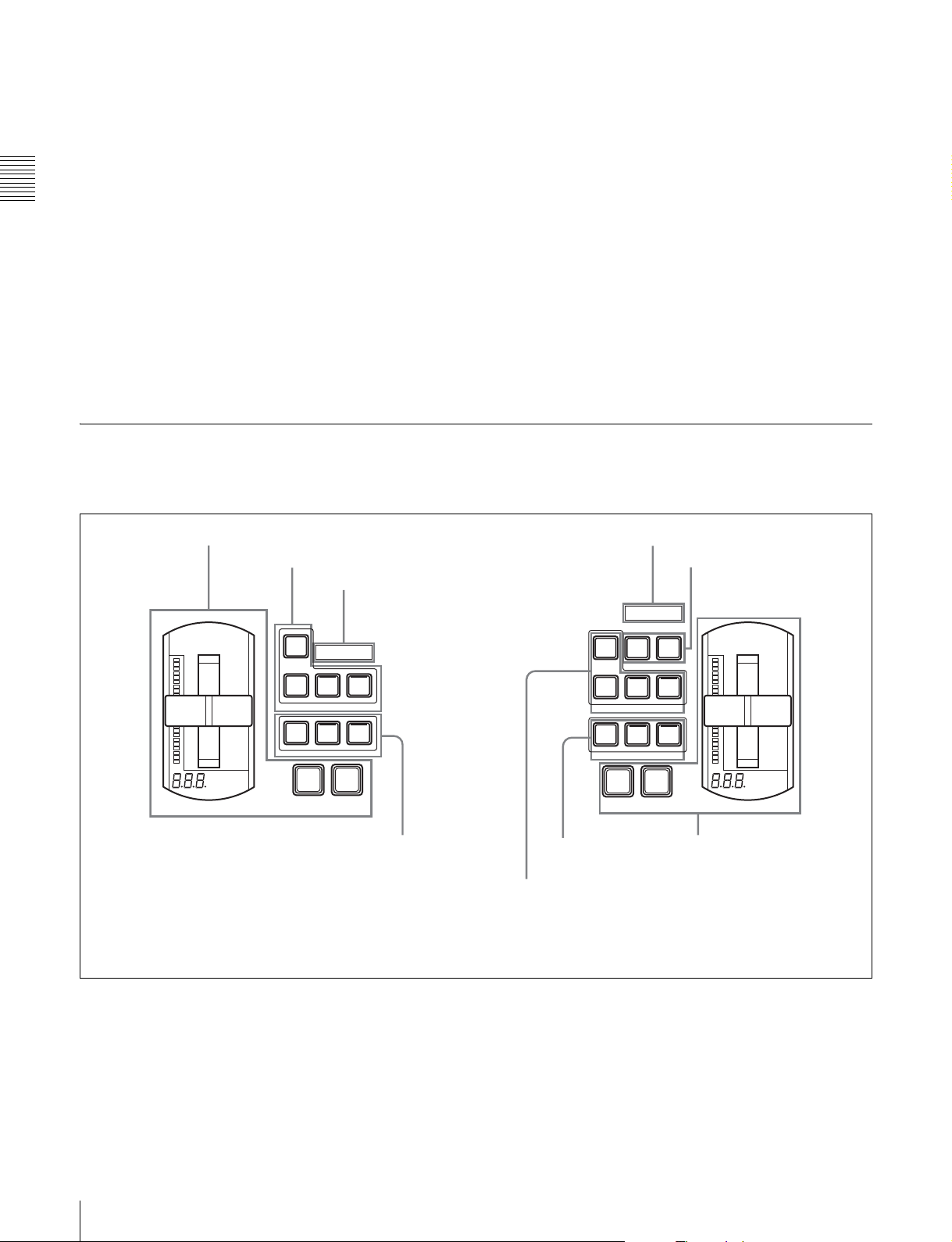
M/E Transition Control Block
Use this block to control transitions in M/E (mix/effect)
program video.
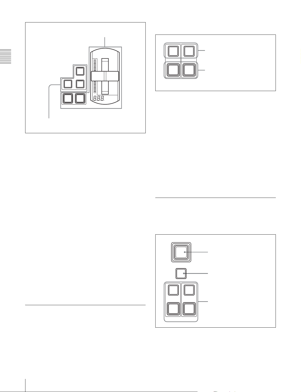
1 Transition execution section
2 Next transition selection buttons
KEY
PRIOR
BKGD KEY1 KEY2
NEXT TRANSITION
MIX EFF
TRANSITION TYPE
FRAMES
M/E transition control
block on 1.5 M/E panel
and 1.5 M/E wide panel
3 OVER indicators
OVER OVER
COLOR
AUTO
CUT
TRANS
PST
MIX
4 Transition type
selection buttons
KEY
PRIOR
BKGD KEY1 KEY2
NEXT TRANSITION
MIX EFF
TRANSITION TYPE
4 Transition type
selection buttons
2 Next transition
selection buttons
3 OVER indicators
5 KEY1 ON and KEY2
ON buttons
OVER OVER
KEY2
KEY1
ON
ON
PST
COLOR
MIX
AUTO
CUT
TRANS
1 Transition execution
M/E transition control
block on 1 M/E panel
FRAMES
section
16 Control Panel Configuration
Page 17
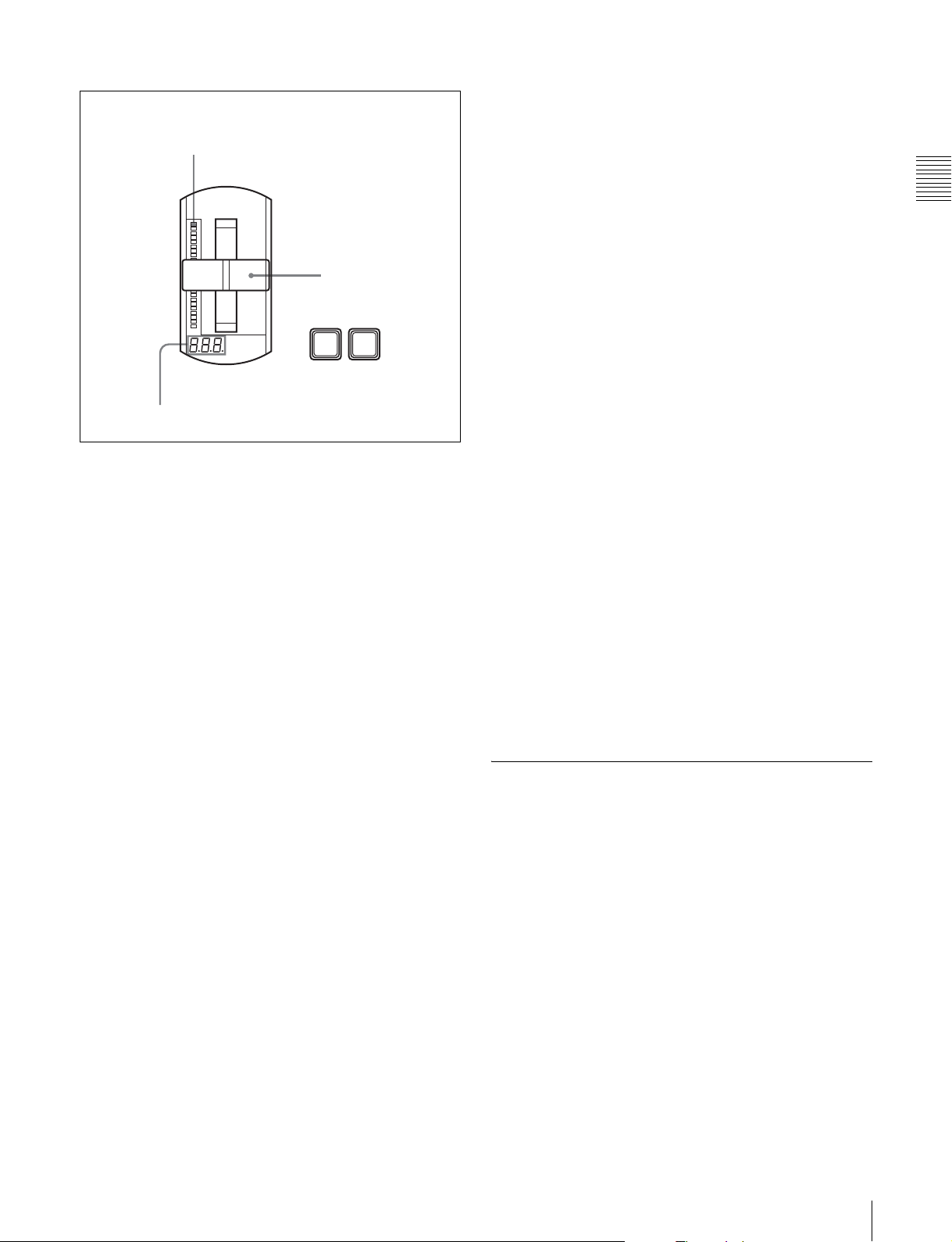
a Transition execution section
(This figure shows the transition execution section on the
1.5 M/E and 1.5 M/E wide panels.)
Transition indicator
Fader lever
AUTO
CUT
TRANS
FRAMES
Transition rate display section
Fader lever: Move the lever up and down to execute the
transition.
Transition indicator: Displays the progress of the
transition with 24 LEDs. The number of lit LEDs
increases as the transition proceeds.
Transition rate display section: Displays the specified
transition rate (the time from the start to the end of the
transition, in units of frames).
c OVER indicators
When key 1 and key 2 are inserted, the OVER indicator for
the key on top lights.
d Transition type selection buttons
To select the type of transition, press one of the following
buttons, turning it on.
MIX: In a background transition, the new video overlaps
the current video, finally replacing it. During the
transition, the sum of the output levels of the A bus and
the B bus is maintained at 100%.
In a key transition, the key fades in (for insertion) or
out (for removal).
EFF (effect): A transition using the selected effect pattern
is executed.
See “Selecting Effects” (page 56) for more
information about how to select effects.
PST (preset) COLOR MIX : This is a two-stage mix
(dissolve), comprising two transitions. In the first
transition, a color matte is gradually mixed into the
current video. In the second transition, the new video
is gradually mixed into the color matte.
You can perform both of these operations in a single
transition.
For details, see “Setting a Preset Color Mix” (page
175).
Chapter 2 Names and Functions of Parts
See “Setting Transition Rates” (page 69) for more
information about how to specify transition rates.
AUTO TRANS (transition) button: Press to execute a
transition automatically at the specified transition rate.
The transition begins immediately, and the button
lights in amber. The button goes out when the
transition finishes.
CUT button: Press to execute an instant transition.
b Next transition selection buttons
To specify which part of the video to switch (change) in
the next transition, press one of the following buttons,
turning it on.
BKGD (background): Switches the background video in
the next transition.
KEY1, KEY2: Press the [KEY1] button, turning it on, to
insert key 1 into the background in the next transition,
or to delete it from the background. If key 1 is not
currently inserted, the transition inserts it. If key 1 is
currently inserted, the transition deletes it. The
[KEY2] button works in the same way.
KEY PRIOR (priority): When key 1 and key 2 are
inserted in an overlapping state, the key on top appears
in front on the monitor. By pressing this button,
turning it on, you can reverse the priority of the two
keys in the next transition.
e KEY1 ON and KEY2 ON buttons
Press the corresponding button to instantly insert or delete
key 1 or key 2. The [KEY1 ON] button lights in red when
key 1 is inserted into the program video (final output
video). Otherwise it lights in amber. The [KEY2 ON]
button works in the same way.
PGM/PST Transition Control Block
Use this block to control program transitions.
This control block is provided only on the 1.5 M/E and 1.5
M/E wide panels.
17Control Panel Configuration
Page 18
1 Transition execution section
panel, where they are located in the M/E transition control
block (see page 16).
KEY1
Chapter 2 Names and Functions of Parts
PST
COLOR
MIX
WIPE
MIX
TRANSITION TYPE
AUTO
CUT
TRANS
FRAMES
AUTO
TRANS
KEY1 KEY2
a KEY1 ON and KEY2 ON buttons
Press the corresponding button to instantly insert or delete
ON
KEY2
ON
AUTO
TRANS
1 KEY1 ON and KEY2 ON buttons
2 AUTO TRANS buttons
key 1 or key 2. The [KEY1 ON] button lights in red when
2 Transition type selection buttons
key 1 is inserted into the program video (final output
video). Otherwise it lights in amber. The [KEY2 ON]
button works in the same way.
a Transition execution section
This works in the same way as the transition execution
section in the M/E transition control block (see page 16).
b AUTO TRANS (transition) buttons
Press the corresponding button to insert or delete key 1 or
key 2 at the specified transition rate. The key fades in
(insert) or fades out (delete). The transition begins as soon
b Transition type selection buttons
To select the type of transition, press one of the following
as the button is pressed, and the button lights in amber. The
button goes out when the transition finishes.
buttons, turning it on.
MIX: In a background transition, the new video overlaps
the current video, finally replacing it. During the
See “Setting Transition Rates” (page 69) for more
information about how to specify transition rates.
transition, the sum of the output levels of the PGM bus
and the PST bus is maintained at 100%.
WIPE: A transition using the selected wipe pattern is
executed, so that the new video wipes away the current
Downstream Key/Fade to Black
Control Block
video.
Use this block to insert and delete downstream keys, and
On how to select a wipe pattern, see “Selecting
to fade to black.
Effects” (page 56).
PST (preset) COLOR MIX: In the first transition, a color
matte is gradually mixed into the current video. In the
second transition, the new video is gradually mixed
into the color matte.
You can perform both of these operations in a single
transition.
For details, see “Setting a Preset Color Mix” (page
175).
M/E Key Transition Control Block
Use this block to insert and delete keys in independent M/
E background video transitions. The transitions are
independent of the transitions performed with the M/E
transition control block (see page 16).
This control block is provided only on the 1.5 M/E and 1.5
M/E wide panels. However, of the four buttons, the [KEY1
ON] and [KEY2 ON] buttons are also found on the 1 M/E
18 Control Panel Configuration
FTB
DSK
PVW
ON
DSK2
ON
AUTO
TRANS
DSK1
AUTO
TRANS
DSK1 DSK2
1 FTB button
2 DSK PVW button
3 DSK independent transition
execution section
a FTB (fade to black) button
Press this button to execute a fade to black at the specified
transition rate. The button lights in amber when pressed. It
lights in red when the fade to black is completed, for as
long as black is output.
Page 19
See “Setting Transition Rates” (page 69) for more
information about how to specify transition rates.
See “Setting Transition Rates” (page 69) for more
information about how to specify transition rates.
b DSK PVW (downstream key preview) button
You can press this button, turning it on, to temporarily
switch M/E PVW output (1 M/E panel) or PST output (1.5
M/E panel) to DSK PVW output.
Note
Whether or not this switching function is available
depends on a setting made in the Output Assign menu. For
details, see “Switching M/E PVW or PST output to DSK
PVW output” (page 156).
c DSK independent transition execution section
DSK1 ON, DSK2 ON buttons: Press the [DSK1 ON]
button to cut downstream key 1 in or out (insert or
delete it instantly). The button lights in red when the
key is inserted in program video (final output video).
Otherwise it lights in amber. The [DSK2 ON] button
works in the same way.
AUTO TRANS buttons: Press the corresponding button
to insert or delete downstream key 1 or 2 at the
specified transition rate. The key is mixed to fade in
(insert) or out (delete). The transition begins as soon as
the button is pressed, and the button lights in amber.
When the transition finishes, the button goes out.
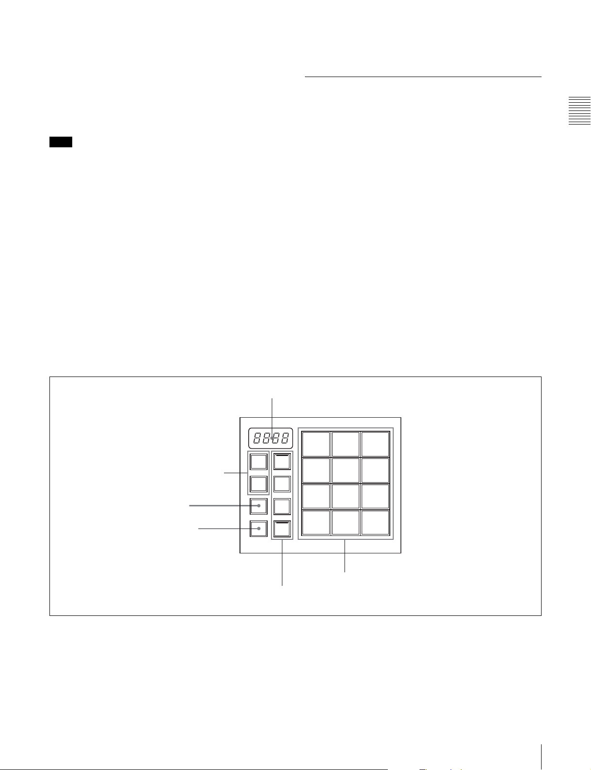
Flexi Pad Control Block
Use the Flexi Pad control block in the following four
operation modes.
• Effect snapshot mode
• Snapshot mode
• Macro mode
• Transition rate input mode
Depending on the operation mode, this control block
allows you to do the following.
In effect snaphot mode:
• Recall, save, and delete effect snapshots
• Recall effect pattern numbers
In snaphot mode:
• Recall, save, and delete snapshots
• Set snapshot attributes
In macro mode:
Recall (execute), save, delete, and edit macros
In transition rate input mode:
Enter transition rates
Chapter 2 Names and Functions of Parts
1 Numeric display
M/E
2 Region selection buttons
3 STORE button
4 BANK SEL button
This figure shows the Flexi Pad control block
in transition rate input mode.
PP/
ALL
STORE
BANK
SEL
a Numeric display
Depending on the operation mode, this shows an effect
pattern number, a bank number, a register number, an
event number, an event total, a pause duration, or a
transition rate, in up to four digits.
In effect snapshot mode: Pattern number
In snapshot mode: Bank number and register number
7 8 9
EFF/
WIPE
SNAP
SHOT
MCRO
TRANS
RATE
5 Mode selection buttons
4 5 6
1 2 3
0
6 Memory recall buttons
In transition rate input mode: Transition rate
Macro mode
• In macro recall mode: A bank number and register
number
• In macro edit mode: An event number and an event
total
• In pause duration entry mode: A pause duration
ENTRTC
19Control Panel Configuration
Page 20

b Region selection buttons
Used in modes other than macro mode.
Select the target function block of the operation. The
button which is on lights in amber.
M/E button: Selects the M/E region.
PP/ALL (PGM/PST/all) button (on 1.5 M/E panel): In
snapshot mode, selects all regions. In transition rate
Chapter 2 Names and Functions of Parts
input mode and effect snapshot mode, selects the
PGM/PST region.
ALL button (on 1 M/E panel): In snapshot mode, selects
all regions. Has no effect in transition rate input mode
and effect snapshot mode.
c STORE button
Used in modes other than transition rate input mode.
This button lights in amber when on, to indicate that you
can save the current snapshot or effect snapshot, enter
macro edit mode, or delete a saved snapshot, effect
snapshot, or macro.
d BANK SEL (selection) button
Used in snapshot mode or macro mode. Has no effect in
other modes.
This button lights in amber when on, to indicate that you
can use the memory recall buttons to specify a snapshot or
macro register bank.
e Mode selection buttons
Select the operation mode of the Flexi Pad control block.
The button currently turned on lights in amber.
EFF/WIPE (effect shapshot): Selects effect snapshot
mode. You can also use this button when selecting
effect patterns.
SNAPSHOT: Selects snapshot mode.
MCRO (macro): Selects macro mode. Lights in amber in
macro recall mode, and lights in red in macro edit
mode.
TRANS RATE: Selects transition rate input mode.
f Memory recall buttons
The configuration of the memory recall buttons changes
according to the operation mode selected with the mode
selection buttons.
In effect snapshot mode: Comprised of the [0] to [9]
buttons, a [PTN NO. (pattern number)] button, and an
[ENTR (enter)] button.
The state and functions of the [0] to [9] buttons and the
[ENTR] button change depending on the state of the
[PTN NO.] button and the [STORE] button.
For details, see “Selecting Effects With the Flexi Pad
Control Block” (page 57).
In snapshot mode: Comprised of the [0] to [9] buttons, an
[EFF DISS (effect dissolve)] button, and an [AUTO
TRNS (transition)] button. The state and functions of
these buttons change depending on the state of the
[BANK SEL] button and the [STORE] button.
For details, see “Saving Snapshots” (page 125).
In macro mode
• In macro recall mode: Comprised of the [0] to [9]
buttons, an [Executed events/Total Events] button,
and a [TAKE] button. The state and functions of the
buttons change depending on the states of the
[BANK SEL] and [STORE] buttons.
• In macro edit mode: Comprised of the [INS (insert)]
button, [MOD (modify)] button, [DEL (delete)]
button, [PAUS (pause)] button, [ALL (select all)]
button, [EXIT] button, [AUTO INS (auto insert)]
button, [STOR/Register Number (Store/register
number)] button, [<< PREV (goto previous event)]
button, and [NEXT >> (goto next event)] button.
• In pause time entry mode: Comprised of the [0] to
[9] buttons, a [CLR (clear)] button, and a [PAUS/
ENTR (pause/enter)] button.
For details, see “Macros” (page 127).
In transition rate input mode: Comprised of the [0] to [9]
buttons, and an [ENTR (enter)] button.
For details, see “Setting Transition Rates” (page 69).
Effect/Wipe Control Block
Use this block to set the direction of effects and wipes. You
can also add modifiers as required.
20 Control Panel Configuration
Page 21
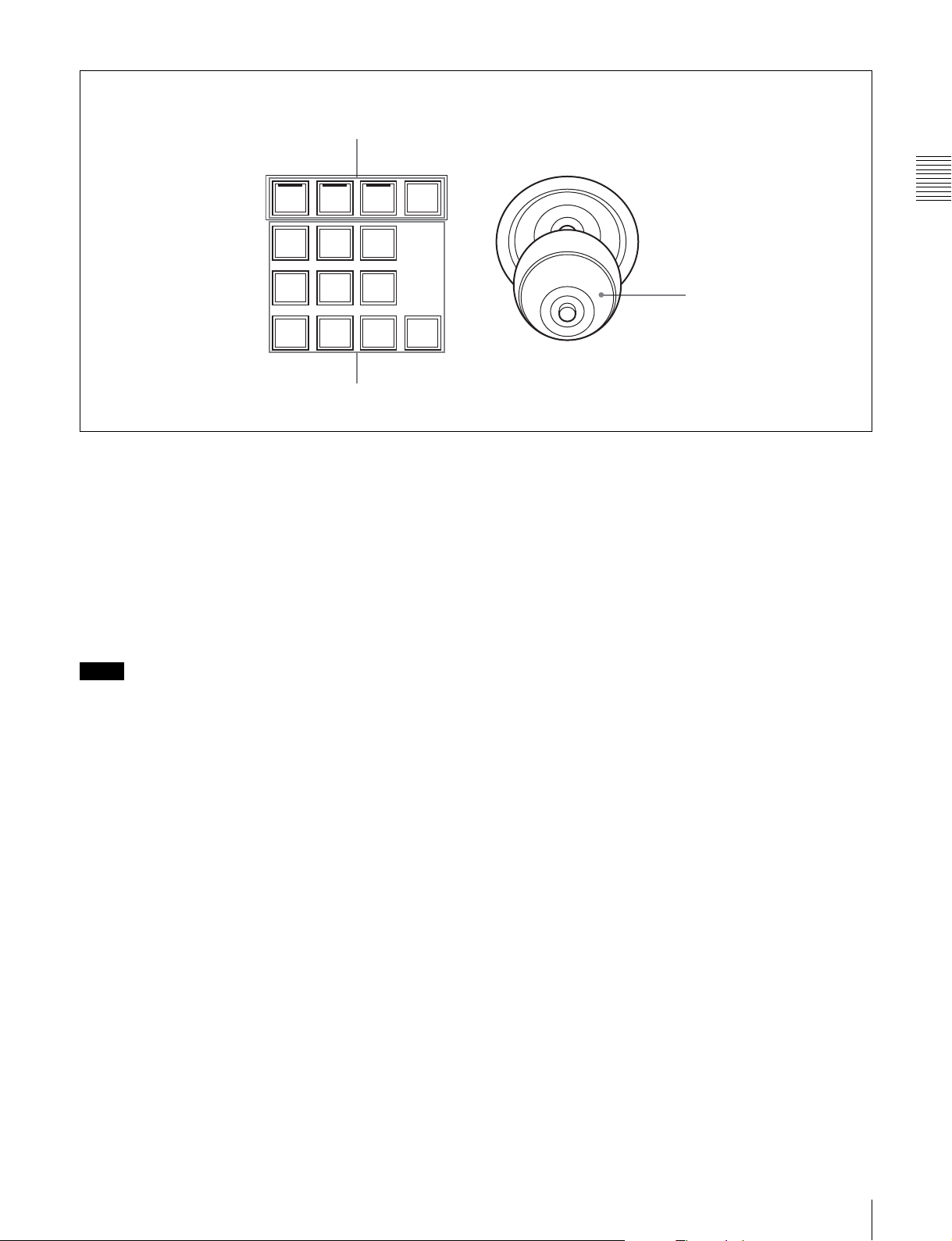
EFFECT
M/E
1CH
BVLD
EDGE
1 Delegation selection buttons
M/E
2CH
LIGHT
TRAIL/
SHDW
MENUP/P
Chapter 2 Names and Functions of Parts
BORD SOFT CROP
N/R REV POS
3 Effect modifier buttons
CTR
a Delegation selection buttons
Select operation targets.
M/E 1CH (M/E1 channel), M/E 2CH (M/E2 channel)
buttons: Select M/E1 channel or M/E2 channel or
both as the operation target(s).
P/P (PGM/PST) button (on 1.5 M/E panels only):
Selects PGM/PST as the operation target.
MENU button: When this button is on, you can use the
joystick to adjust the lefttmost three parameters
assigned to the knobs in the menu control block.
Notes
• The [M/E 2CH] button does not light and cannot be
selected for effect patterns with numbers lower than
2000.
• When the [SHTL] button or [JOG] button in the utility
control block is on, turning a delegation selection button
on turns the [SHTL] button or [JOG] button off. (The
button pressed later receives priority).
2 Joystick
When the [MENU] button is on, you can use this to adjust
parameters. Operation of the joystick is linked with
operation of the knobs in the menu control block.
Parameter assigned to knob 1: The value increases when
the joystick is moved to the right, and decreases when
the joystick is moved to the left.
Parameter assigned to knob 2: The value increases when
the joystick is moved away from you, and decreases
when the joystick is moved toward you.
Parameter assigned to knob 3: The value increases when
the knob of the joystick is rotated clockwise, and
decreases when it is rotated counterclockwise.
The adjustment range depends on the parameter.
When the [SHTL] button or [JOG] button in the utility
control block is on, the joystick can be used to control jog
and shuttle mode search on devices.
Move the joystick to the right for forward direction search,
and left for reverse direction search.
b Joystick
When one of the [M/E 1CH], [M/E 2CH], and [P/P]
buttons is on, you can use the joystick to adjust the position
of the currently selected effect pattern. For some effect
patterns, the joystick can be used to change their size.
X-axis position: The X value increases when the joystick
is moved to the right, and decreases when the joystick
is moved to the left.
Y-axis position: The Y value increases when the joystick
is moved away from you, and decreases when the
joystick is moved toward you.
Size: The value increases when the knob of the joystick is
rotated clockwise, and decreases when it is rotated
counterclockwise.
c Effect modifier buttons
BVLD (beveled) EDGE: When this button is on, you can
add beveled edges to the image. This button lights in
green when beveled edge parameters are assigned to
the knobs in the menu control block, and lights in
amber when no beveled edge parameters are assigned
to the knobs.
LIGHT (lighting): When this button is on, you can add a
lighting effect to the image. This button lights in green
when lighting parameters are assigned to the knobs in
the menu control block, and lights in amber when no
lighting parameters are assigned to the knobs.
TRAIL/SHDW (shadow): When this button is on, you
can add a shadow to the image. This button lights in
green when shadow parameters are assigned to the
knobs in the menu control block, and lights in amber
when no shadow parameters are assigned to the knobs.
21Control Panel Configuration
Page 22
BORD (border): When this button is on, you can add
borders. The button lights in amber when no border
parameters have been assigned to the knobs in the
menu control block, and lights in green when they
have been assigned.
SOFT (soft edges): When this button is on, you can add
soft edges. The button lights in amber when no soft
Chapter 2 Names and Functions of Parts
edge parameters have been assigned to the knobs in the
menu control block, and lights in green when they
have been assigned.
CROP button: When this button is on, you can perform
cropping. The button lights in amber when no crop
parameters have been assigned to the knobs in the
menu control block, and lights in green when they
have been assigned.
N/R (normal/reverse): When this button is on, it lights in
amber and the transition direction reverses every time
a transition finishes.
REV: When this button is on, it lights in amber and the
transition direction reverses.
POS (position) button: You can turn the positioner on
and use the joystick to move effect patterns in the xaxis and y-axis directions, and to change their size.
CTR (center) button: When the [POS] button is on,
pressing this button returns an effect pattern to the
default position and size.
Utility Control Block
ENABLE/UTILITY
EDIT GPI
DEVICE/UTILITY
DEV1 JOGDEV2 PLAY STOP
SAFE
TITLE
1 ENABLE/UTILITY operation buttons
ALL
STOP
CUE
START
TC
a ENABLE/UTILITY operation buttons
You can assign utility commands to these buttons.
The following utility commands are assigned by default.
EDIT button: Enables and disables the switcher edit
mode.
GPI button: Enables and disables switcher GPI.
SAFE TITLE button: Turns on and off a marker showing
the television reception safe area and a cross marker
showing the center of the screen.
Blank button: No function assignment.
See “Utility Settings (Utility Menu)” (page 170) for more
information about how to assign arbitrary utility
commands to these buttons.
SHTL
2 DEVICE/UTILITY operation buttons
JOG: Turns jog mode on and off.
Note
When a delegation selection button is on, turning the
[SHTL] or [JOG] button on turns the delegation button off.
(The button pressed later receives priority).
See “Utility Settings (Utility Menu)” (page 170) for more
information about how to assign arbitrary utility
commands to these buttons.
b DEVICE/UTILITY operation buttons
You can assign utility commands to these buttons.
The following utility commands are assigned by default.
DEV1/DEV2: Selects the Device1/Device2 as control
target.
PLAY: Plays a tape or disk.
STOP: Stops a tape or disk.
ALL STOP: Stops tapes or disks on all devices.
CUE: Cue up.
START TC: Sets the current timecode as the start point.
SHTL: Turns shuttle mode on and off.
22 Control Panel Configuration
Page 23
Macro Control Block
Menu Control Block
MACRO
PRE
MCRO
1 PRE MCRO button
POST
MCRO
2 POST MCRO button
ATTCH
ENBL
3 ATTCH ENBL button
a PRE MCRO button
Use this button to set a macro attachment in pre macro
mode.
When you make settings in macro only mode, this button
is used together with the Macro Only Set button, assigned
to one of the buttons in the utility control block.
b POST MCRO button
Use this button to set a macro attachment in post macro
mode.
When you make settings in macro only mode, this button
is used together with the Macro Only Set button, assigned
to one of the buttons in the utility control block.
1 Top menu selection buttons
Menu display
MENU
TOP/
SHUT
DOWN
REG
FILE
SET
UP
DIAG
2 Knobs
a Top menu selection buttons
Select the menu shown in the menu display.
• TOP/SHUTDOWN (top menu/shutdown) button
• REG (register menu) button
• FILE (file menu) button
• SET UP (setup menu) button
• DIAG (diagnostics menu) button
Chapter 2 Names and Functions of Parts
c ATTCH ENBL (attachment enable) button
When this button is on, macro attachments assigned to
buttons on the control panel are enabled.
b Knobs
Use to adjust parameters shown in the menus.
Power Indicators, “Memory Stick” Slot, USB Connector
A POWER B
a Power A and B status indicators
Two power supplies (A and B) can be installed in the
control panel. When the control panel is powered on, the
indicators corresponding to the installed power supplies
light in green.
1 Power A and B status indicators
2 “Memory Stick” status indicator
3 “Memory Stick” slot
4 USB connector
23Control Panel Configuration
Page 24

Installing a second power supply requires the optional HKPSU11 Power Supply Unit.
b “Memory Stick” status indicator
Lights in red during access to a “Memory Stick.”
“Memory Sticks”
Usable “Memory Sticks”
c “Memory Stick” slot
Chapter 2 Names and Functions of Parts
Insert “Memory Sticks.”
See ““Memory Sticks”” (page 24) for more information
about the usable “Memory Sticks” and their handling.
d USB connector
Devices compatible with the USB 1.1 standard can be
connected. Currently this connector is not used.
The following types of “Memory Stick” can be used with
this system.
• MSH-32/64/128 “Memory Stick”
• MSX-256S/512S/1GS “Memory Stick PRO”
• MSH-M32N/M64N/M128N “Memory Stick Duo”
• MSX-M256S/M512S “Memory Stick PRO Duo”
Notes
• When using a “Memory Stick PRO,” high-rate data
transfer using parallel interface is not supported.
• This system does not support the MagicGate function.
• When using a “Memory Stick Duo,” be sure to use it
with a “Memory Stick Duo Adaptor” (MSAC-M2 or
equivalent). If you insert a “Memory Stick Duo” without
using the adaptor, there is the possibility that the stick
cannot be removed, resulting in a serious accident.
Handling “Memory Sticks”
When using “Memory Sticks,” pay attention to the
following points.
• Do not touch the connector of the “Memory Stick” with
anything, including your finger or metallic objects.
• Do not attach anything other than the supplied label to
the “Memory Stick” labeling position.
• Attach the label so that it does not stick out beyond the
labeling position.
• Carry and store the “Memory Stick” in its case.
• Do not strike, bend, or drop the “Memory Stick.”
• Do not disassemble or modify the “Memory Stick.”
• Do not allow the “Memory Stick” to get wet.
• Do not use or store the “Memory Stick” in a location that
is:
-Extremely hot, such as in a car parked in the sun
-Under direct sunlight
-Very humid or subject to corrosive substances
24 “Memory Sticks”
Page 25
Using Menus
Accessing Menus
The menus of this switcher enable you to make system settings and settings
related to effects.
To access menus, you can use any of the following three methods.
• Access from the top menu (see next section)
• Access by double clicking (see page 26)
• Access by single clicking (see page 28)
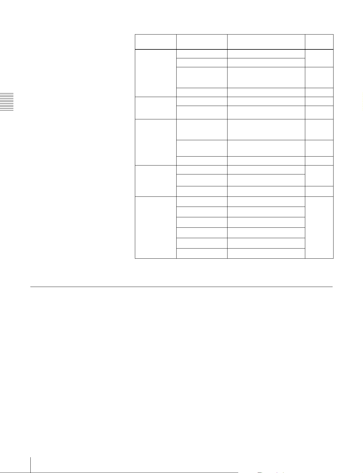
Accessing Menus From the Top Menu
By pressing a top menu selection button in the menu control block (see page
23), you can directly access the menu page for that button. The menus which can
be accessed with top menu selection buttons are as follows.
Menus accessed with top menu selection buttons and their functions
Chapter
Button Menu Function Reference
page
TOP/SHUTDOWN Top/Shutdown Display the top menu, and
REG
FILE
SET UP
DIAG Diagnosis Display error status and
a) The most recently used menu is displayed.
b) Currently not supported.
Register
File
Setup/Diagnosis
a), b)
a)
exit the menu system.
Make register settings. –
Make file settings. Page 137
a)
Make settings related to
setup, and to display of
error status and error
logs.
error logs.
Page 42
Page 153
“Error
Messages”
in the
Appendix
(separate
document)
To access a menu from the top menu, proceed as follows.
25Accessing Menus
Page 26
Note
The menu illustrations in this manual may differ in appearance from the menus
actually shown in the menu display of the control panel.
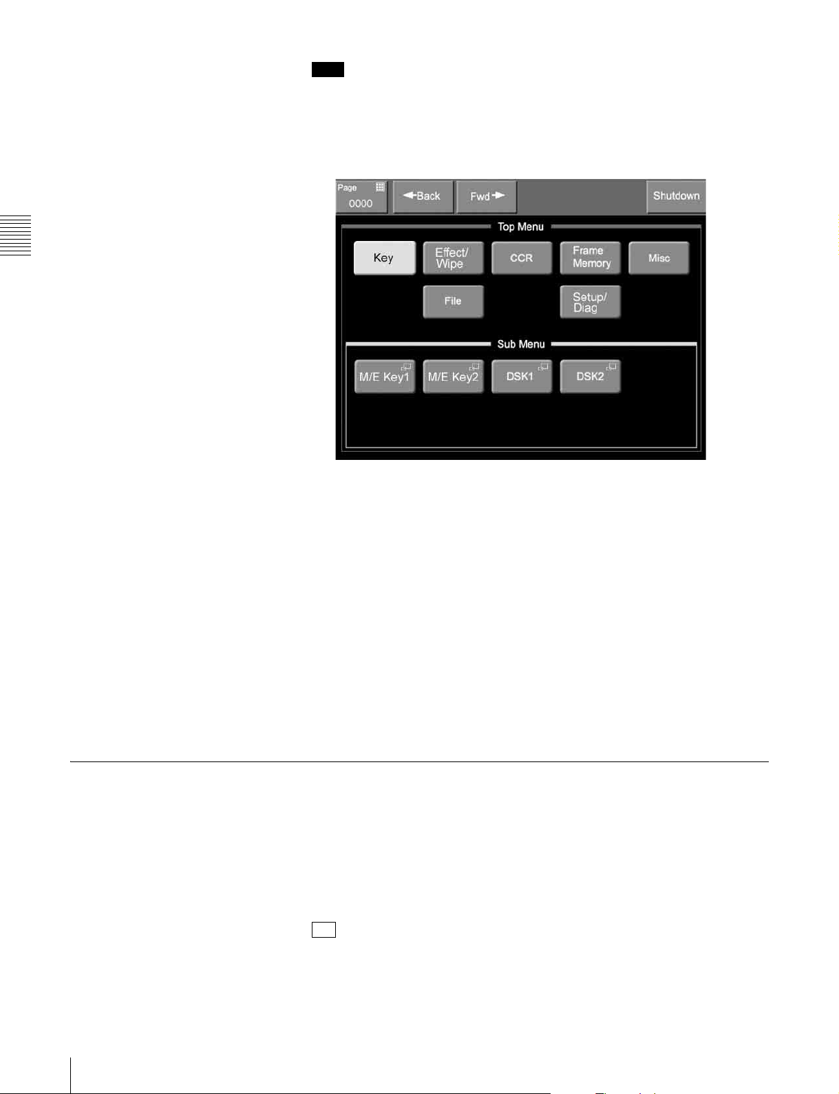
1
Press the [TOP/SHUTDOWN] button in the menu control block.
The top menu appears.
Chapter 3 Using Menus
Tip
If you press the [FILE], [SET UP], or [DIAG] button, the page for that
button appears.
2
In the Top Menu area, select a menu.
The second-level menu of the menu selected in the Top Menu area appears
in the Sub Menu area.
3
Select a menu in the Sub Menu area.
If the menu has only two levels, the page for the second-level menu appears.
If the menu has three levels, a popup window appears so that you can select
a third-level menu.
4
Select a menu from the popup window.
The third-level menu appears.
Accessing Menus by Double Clicking
This manual uses the term “double click” to refer to the action of pressing a
button on the control panel twice in rapid succession (comparable to double
clicking a computer mouse button). You can double click many of the buttons
on the control panel except the top menu selection buttons to directly access
menus related to those buttons. The following table shows the buttons which
access menus by double clicking and the accessed menus.
26 Accessing Menus
Tip
The ability to access menus by double clicking is indicated by a horizontal bar
on the face of the button, located over the button name.
Page 27
Menus accessed by double clicking
Button
location
M/E cross-point
control block
PGM/PST
cross-point
control block
b)
AUX bus
control block
(cross-point
button rows)
AUX bus
control block
(AUX
delegation
buttons)
Button Menu Referenc
e page
a)
COLOR BKGD
FM1 VIDEO
FM1 KEY
FM2 VIDEO
FM2 KEY
FM3 VIDEO
FM3 KEY
CCR1
CCR2
a)
a)
a)
a)
a)
a)
a)
a)
COLOR BKGD
FM1 VIDEO
FM1 KEY
FM2 VIDEO
FM2 KEY
FM3 VIDEO
FM3 KEY
CCR1
CCR2
a)
a)
a)
a)
a)
a)
a)
a)
COLOR BKGD
FM1 VIDEO
FM1 KEY
FM2 VIDEO
FM2 KEY
FM3 VIDEO
FM3 KEY
CCR1
CCR2
a)
a)
a)
a)
a)
a)
a)
a)
Misc >Color Bkgd Page 88
Frame Memory >Recall Page 122
Frame Memory >Recall
Frame Memory >Recall
Frame Memory >Recall
Frame Memory >Recall
Frame Memory >Recall
CCR >CCR1 >Primary Page 113
CCR >CCR2 >Primary
a)
Misc >Color Bkgd Page 88
Frame Memory >Recall Page 122
Frame Memory >Recall
Frame Memory >Recall
Frame Memory >Recall
Frame Memory >Recall
Frame Memory >Recall
CCR >CCR1 >Primary Page 113
CCR >CCR2 >Primary
a)
Misc >Color Bkgd Page 88
Frame Memory >Recall Page 122
Frame Memory >Recall
Frame Memory >Recall
Frame Memory >Recall
Frame Memory >Recall
Frame Memory >Recall
CCR >CCR1 >Primary Page 113
CCR >CCR2 >Primary
KEY1 Key >M/E Key1 >Main Page 76
KEY2 Key >M/E Key2 >Main
DSK1 Key >DSK1 >Main
DSK2 Key >DSK2 >Main
CCR1 CCR >CCR1 >Primary Page 113
CCR2 CCR >CCR2 >Primary
FRAME MEM Frame Memory >Freeze Page 120
Chapter 3 Using Menus
27Accessing Menus
Page 28
Menus accessed by double clicking
Button
location
M/E transition
control block
PGM/PST
transition
Chapter 3 Using Menus
control block
Flexi Pad
control block
Effect/Wipe
control block
Utility control
block
Button Menu Referenc
KEY1 Key >M/E Key1 >Main Page 76
KEY2 Key >M/E Key2 >Main
EFF Effect/Wipe >M/E Effect >Main Page 63
PST COLOR MIX Misc >Transition Page 54
WIPE Effect/Wipe >P/P Wipe >Main –
PST COLOR MIX Misc >Transition Page 54
b)
M/E + EFF/WIPE Effect/Wipe >M/E Effect >Main Page 63
PP/ALL + EFF/
b)
WIPE
TRANS RATE Misc >Transition Page 70
M/E 1CH Effect/Wipe >M/E Effect >Main Page 63
M/E 2CH Effect/Wipe >M/E Effect >Main
b)
P/P
Device1
Device2
Device3
Device4
Device5
Device6
c)
c)
c)
c)
c)
c)
Effect/Wipe >P/P Wipe >Main –
Effect/Wipe >P/P Wipe >Main –
Misc >DDR/VTR >TC Status Page 147
Misc >DDR/VTR >TC Status
Misc >DDR/VTR >TC Status
Misc >DDR/VTR >TC Status
Misc >DDR/VTR >TC Status
Misc >DDR/VTR >TC Status
e page
Page 66
Page 71
Page 66
Page 71
Page 66
Page 71
a) Button assigned with Video/Key Pair Assign menu (see page 159).
b) Not found on 1 M/E panel.
c) Button assigned with Utility menu (see page 170).
Accessing Menus by Single Clicking
A menu appears when you single click a parameter adjustment button to turn the
adjustment function on (and the knobs take on the parameters which can be
assigned for the adjustment). The buttons which access menus by single clicking
are the following buttons in the Effect/Wipe control block.
• [BVLD EDGE] button
• [LIGHT] button
• [TRAIL/SHDW] button
• [BORD] button
• [SOFT] button
• [CROP] button
28 Accessing Menus
Page 29
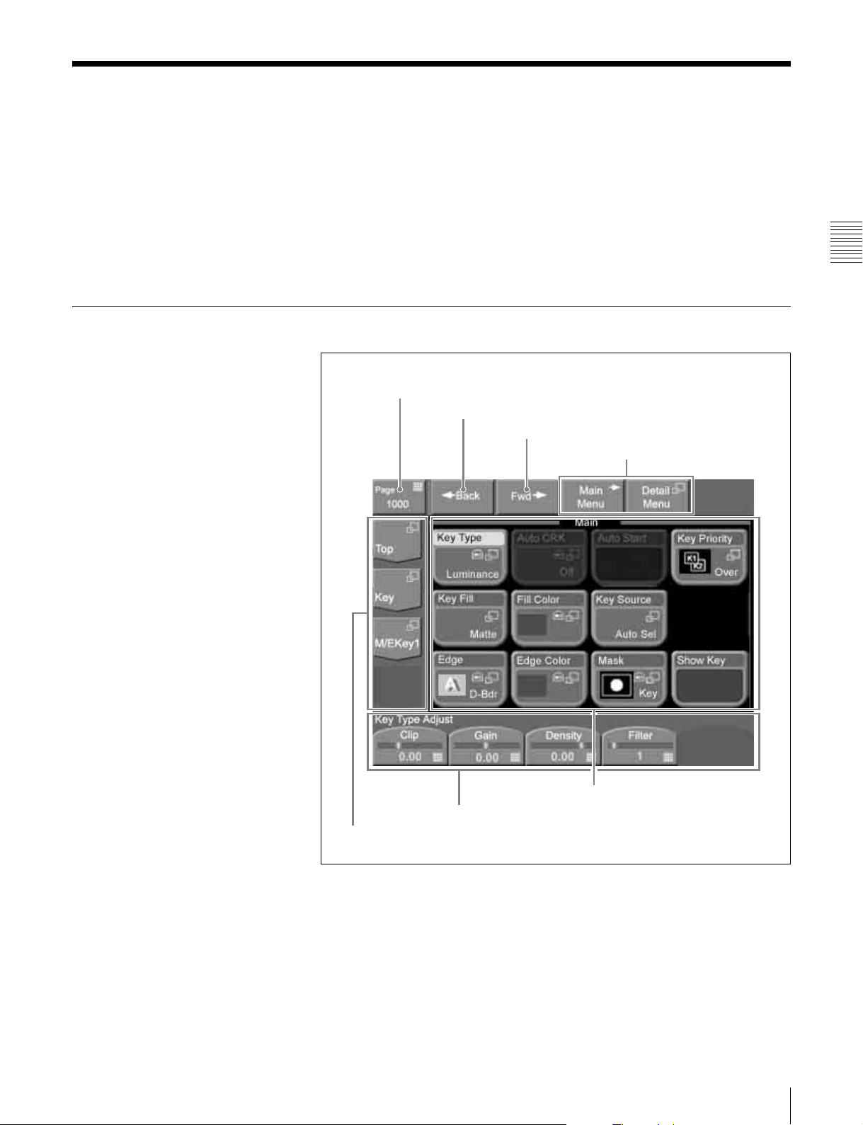
Interpreting Menu Screens
There are two types of menu screen.
• Basic screen (see next section)
• Popup windows
- General popup windows (see page 32)
- General popup windows (scrolling type) (see page 33)
- Numeric keypad window/timecode window (see page 33)
- Hexadecimal keypad window (see page 35)
- Keyboard window (see page 36)
- Page number input window (see page 38)
Basic Screen
1 Menu page number button
Chapter 3 Using Menus
2 Back button
3 Fwd button
4 Menu switch buttons
7 Button area and status area
6 Parameter buttons
5 Menu title buttons
(The figure shows a button
area only.)
a Menu page number button
This shows the menu screen page number.
When you press this button, the page number input window (see page 38)
appears. Enter a page number in that window to display the desired menu.
For details about operation, see “Selecting menus by entering page numbers”
(page 40).
29Interpreting Menu Screens
Page 30

For details about page numbers, refer to “Menu Tree” in the Appendix
(separate document).
b Back button
Returns to the most recently displayed menu. You can go back up to maximum
of 50 menus.
This button is disabled when the display history has been erased and when you
have backed up through the entire display history.
For details about operation, see “Selecting menus from the display history”
(page 40).
Chapter 3 Using Menus
c Fwd (forward) button
Redisplays the menu that was visible when you last pressed the Back button.
This button is disabled when the display history has been erased, when you have
moved forward through the entire display history, and when the display history
has been updated by displaying a new menu.
For details about operation, see “Selecting menus from the display history”
(page 40).
d Menu switch buttons
You can use the following buttons to switch between the menus when you have
selected a Key menu or an Effect/Wipe menu.
Main Menu button: Displays a menu with frequently used items.
Detail Menu button: Displays a popup window for selecting menus to make
detailed settings.
e Menu title buttons
Except for the Top button, these buttons display the title of the selected of the
selected menu. The upper buttons correspond to upper level menus. In the
example of the previous figure, [Top] is the top menu, [Key] is a first-level
menu, and [M/E Key1] is a second-level menu.
When you press a button, a popup window appears to allow you to select a menu
from the next level.
For details about operation, see “Selecting by navigating the menu tree” (page
39).
30 Interpreting Menu Screens
f Parameter buttons
Parameters adjustable by knobs and their values are shown on the buttons.
When you press one of these buttons, the numeric keypad window (see page 33)
opens so that you can enter a setting value.
g Button area and status area
The button area displays the buttons of the operation target items in the selected
menu.
In the setup menu and other menus, a status area may also be displayed to show
lists for selecting setting values (see following figure).
Page 31

Status area
Button area
Interpreting buttons
The following figure shows the information displayed on function buttons.
Function name
Lights in light blue when parameters
are assigned to knobs.
Chapter 3 Using Menus
Icon
Status display
The following table shows how to interpret other buttons.
Name Display State
Parameter
button
Execute button Not executing function.
Value displayed. Value can be changed.
Executing function (lit in light purple).
31Interpreting Menu Screens
Page 32

Icons displayed on buttons
The following table shows the icons which are displayed on buttons, and the
functions which they represent. The functions are executed when a button with
the corresponding icon is pressed.
Name Display Function
Popup icon Open a popup window.
Numeric keypad
icon
Chapter 3 Using Menus
Keyboard icon Open the keyboard window.
Shortcut icons Switch the menu display.
Close icon Close a popup window.
Scroll icons • Scroll the function button area.
Knob assigner
icon
Window hold
icon
Open the numeric keypad window, the
timecode window, the hexadecimal keypad
window, or the page number input window.
• Scroll the list in the status area.
• Switch a pattern.
Assign a parameter to a knob.
Do not close a popup window even when a
function selection button is pressed.
Popup Windows
General popup windows
When you press a button with the icon, a popup window opens in the basic
screen.
The popup window may be the scrolling type. For details, see the next section.
2 Close button
1 Function button area
a Function button area
Displays functions and menus for selection. The currently selected button lights
in light blue.
The popup window closes when you press a button in this area.
32 Interpreting Menu Screens
Page 33

b Close button
Closes the popup window.
General popup windows (scrolling type)
3 Window Hold button
1 Function button area
4 Page Up, Page Down buttons
2 Scroll buttons
Chapter 3 Using Menus
5 Close button
a Function button area
Displays functions and menus for selection.
The popup window closes when you press a button in this area. However, it does
not close if the [Window Hold] button is on.
b Scroll buttons
Scroll the function button area up and down.
c Window Hold button
Press this button, turning it on, if you want to keep the window open even after
pressing a button in the function button area.
d Page Up, Page Down buttons
Scroll the function button area up and down in page units.
e Close button
Closes the popup window (even when the [Window Hold] button is on).
Numeric keypad window/timecode window
The numeric keypad window or timecode window opens when you press a
button which is associated with parameter numeric input or timecode input. The
icon appears on the button.
33Interpreting Menu Screens
Page 34

1 Input value display
2 Minimum to maximum display
3 Item display
4 – (minus) button
5 Close button
Chapter 3 Using Menus
8 Clear button
7 Enter button
6 Numeric input buttons
a Input value display
Shows the value entered in the numeric keypad window or the timecode
window.
In the timecode window, values are shown in the format HH:MM:SS:FF
(Hours:Minutes:Seconds:Frames).
About timecode input
• A colon (:) is displayed automatically after every second digit when you enter
three or more digits.
• Timecode is displayed in red if an entered value exceeds the setting range.
Timecode input examples
The following table shows examples of timecode input
Digits entered Display Setting value
[1], [2] 12 00:00:00:12
[1], [2], [2], [0] 12:20 00:00:12:20
[1], [2], [2], [0], [5] 1:22:05 00:01:22:05
34 Interpreting Menu Screens
b Minimum to maximum display
Displays the minimum and maximum values that can be set for the parameter.
Does not display anything in the timecode window.
Page 35

c Item display
Displays the name of the parameter being set in the numeric keypad window or
timecode window.
d – (minus) button
Changes the sign of the input value.
Each press toggles between plus (+) and minus (–).
Not supported in the timecode window.
e Close button
Closes the numeric keypad window or the timecode window.
Hexadecimal keypad window
f Numeric input buttons
Use these buttons to enter the value you want to set.
In the timecode window, the [.] button changes into a [00] button.
g Enter button
Confirms the entered value.
If the value is valid, the numeric keypad window or the timecode window
closes.
If the value is not valid, the window stays open and the color of the input value
display changes to red.
h Clear button
Clears the input. However, parameter settings are not changed.
The hexadecimal keypad window opens when you press a button which is
associated with hexadecimal parameter input. The icon appears on the
button.
1 Input value display
2 Item display
3 Minimum to maximum display
4 Close button
Chapter 3 Using Menus
6 Clear button
5 Enter button
35Interpreting Menu Screens
Page 36

a Input value display
Shows the value entered in the hexadecimal keypad window.
b Item display
Displays the name of the parameter being set in the hexadecimal keypad
window.
c Minimum to maximum display
Displays the minimum and maximum values that can be set for the parameter.
d Close button
Closes the hexadecimal keypad window.
Chapter 3 Using Menus
e Enter button
Confirms the entered value.
If the value is valid, the hexadecimal keypad window closes.
If the value is not valid, the hexadecimal keypad window stays open and the
color of the input value display changes to red.
f Clear button
Clears the input. However, parameter settings are not changed.
Keyboard window
The keyboard window opens in the basic screen when you press a button with
the icon.
36 Interpreting Menu Screens
Page 37

1 Item display
6 Caps Lock button
2 Input string display
3 Left button
4 Right button
5 Close button
Chapter 3 Using Menus
qa Enter button
q; Del button
9 Clear button
8 BS button
7 Shift button
a Item display
Shows the name of the parameter being set in the keyboard window.
b Input string display
Shows the character string being input in the keyboard window.
c Left button
Moves the cursor one character to the left in the input string.
d Right button
Moves the cursor one character to the right in the input string.
e Close button
Closes the keyboard window.
f Caps Lock button
Switches between input of capital letters and lowercase letters.
g Shift button
Enables input of characters on the shift side of the buttons. The shift is released
when you enter a character.
h BS (backspace) button
Clears the character immediately before the cursor in the input string.
37Interpreting Menu Screens
Page 38

i Clear button
Clears all of the characters in the input string.
j Del (delete) button
Clears the character immediately after the cursor in the input string.
k Enter button
Sets the input string as a parameter value.
Closes the keyboard window if the value was valid. If the value was not valid,
the window stays open and the color of the input value display
changes to red.
Chapter 3 Using Menus
Page number input window
The page number input window opens in the basic screen when you press a
menu page number button.
1 Input value display
2 Item display
3 Clear button
38 Interpreting Menu Screens
5 Close button
4 Enter button
a Input value display
Shows the value entered in the page number input window.
b Item display
Shows that the value you are entering is a page number.
c Clear button
Clears the input value.
d Enter button
Confirms the input value.
e Close button
Closes the page number input window.
Page 39

Basic Menu Operations
Selecting Menus
There are three ways to select menus.
• Navigate the menu tree (see next section)
• Enter a page number (see page 40)
• Select from the display history (see page 40)
Selecting by navigating the menu tree
You can display a desired menu by navigating to it through the menu tree from
the currently displayed menu.
The following example shows how to select the Color Bkgd menu under the
Misc menu when you are in the Main menu under a Key menu for the M/E bank.
In this manual, menu names and paths are indicated in the fashion “Key >M/E
Key1 >Main.”
1
3
2
Menu tree
Key
Effect/Wipe
CCR
Frame Memory
Misc
ME Key 1
Transition
Color Bkgd
Enable
DDR/VTR
Chapter 3 Using Menus
Main
4
1
Press [Top].
A popup window for selection of first-level menus appears.
2
Select [Misc].
The popup window closes and the display changes to the Misc menu. The
display on the second and third menu title buttons from the top changes to
the display of the Misc menu.
3
Press the second menu title button from the top.
A popup window for selection of second-level menus appears.
39Basic Menu Operations
Page 40

4
Select [Color Bkgd].
The popup window closes and the display changes to the Color Bkgd menu.
Selecting menus by entering page numbers
You can display a desired menu by entering its page number.
For more information about page numbers, refer to “Menu Tree” in the
Appendix (separate document).
1
Press the menu page number button.
Chapter 3 Using Menus
The page number input window (see page 38) appears.
2
Enter the page number of the desired menu and press the [Enter] button.
The page number input window closes and the display changes to the
desired menu.
Selecting menus from the display history
You can redisplay menus that have appeared in the past.
For example, if you have displayed menus in the order 1000 t 2000 t 3000
t 4000, you can go back to menu 2000 by pressing the [Back] button twice.
After using the [Back] button, you can return in the reverse direction by using
the [Fwd] button. In the above example, press the [Fwd] button twice to return
to menu 4000.
Selecting Functions
To select a function, press the corresponding button in the button area of the
basic screen.
The selected button lights in light blue.
Depending on the button, a popup window may appear so that you can select
further items. Functions may also be assigned to knobs.
See “Interpreting buttons” (page 31) for illustrations of how buttons change in
appearance when they are selected.
Setting Parameters
40 Basic Menu Operations
Parameter buttons light in light blue when they are pressed, and the parameters
are assigned to knobs. Also, the parameter group name appears above the
parameter button group. When you press a button to which a parameter has been
assigned, the numeric keypad window opens so that you can input a numeric
value. Or you may be able to set the parameter by rotating a knob. Parameters
are assigned to knobs 1 to 5 in the order of parameter buttons from the left.
When 6 or more parameters have been assigned, the 5th button functions as a
page switch button (the [More] button). For example, when 8 parameters have
been assigned, buttons 1 to 4 on menu page 1/2 are assigned to knobs 1 to 4
initially, and buttons 5 to 8 on menu page 2/2 are assigned to knobs 1 to 4 by
page switching.
Page 41

Parameter group name
Knob 1 Knob 2
Parameter values can be set with either of the following methods.
• Rotate the knobs (1 to 5) corresponding to the parameters.
• Press the parameter button corresponding to a parameter, and enter a numeric
value in the numeric keypad window.
Parameter values are indicated by the length of the bars on the buttons and by
the numeric values under the bars.
In explaining specific operations, this manual gives examples of typical knob
settings, expressed as shown below.
Example 1: When a pattern key is selected
Knob Description Setting values
1 (Size) Size of pattern 0.00 to 100.00
2 (Soft) Softness of edge width 0.00 to 100.00
3 (Density) Key density 0.00 to 100.00
4 (Pattern) Pattern number 1 to 24
Example 2: When a video process is selected
(The buttons of parameter group 1/2 are shown first, changing to parameter
group 2/2 when the [More] button in the position of knob 5 is pressed.
Knob 3 Knob 4 Knob 5
Chapter 3 Using Menus
Parameter group 1/2
Knob Description Setting values
2 (Video Gain) Overall gain of video signals –200.00 to +200.00
3 (Y Gain) Gain of luminance signals –200.00 to +200.00
4 (Black Level) Black level –7.30 to +109.58
Parameter group 2/2
Knob Description Setting values
2 (Video Gain) Overall gain of video signals –200.00 to +200.00
3 (C Gain) Gain of chrominance signals –200.00 to +200.00
4 (Hue Delay) Amount of hue offset –180.00 to +180.00
41Basic Menu Operations
Page 42

Exiting the Menu System
To exit the menu system, proceed as follows.
Note
Always exit the menu system before powering the control panel off.
1
In the menu control block, press the [TOP/SHUTDOWN] button.
Chapter 3 Using Menus
The top menu appears.
2
Press [Shutdown].
A confirmation popup window appears.
3
Press [Yes].
This shuts down the menu system after a while, and the menu display
changes to black. Now power off the system.
To cancel the exit
Press [No].
To restart the menu system
Power on the control panel once more.
42 Exiting the Menu System
Page 43

Basics of Video
Switching
This chapter begins by explaining how to switch background signals on the M/
E bank (how to perform transitions). Then it explains basic background video
switching on the PGM/PST bank when a 1.5 M/E panel or 1.5 M/E wide panel
is used.
The examples in this chapter assume that the following signals are currently
selectable with the 2nd, 3rd, and 4th cross-point buttons from the left.
Signal selectable with the 2nd button from the left: Landscape
video signal
Signal selectable with the 3rd button from the left: Lion video signal
Chapter
Signal selectable with the 4th button from the left: Castle video
signal
43
Page 44

Basic Operations (1): Video Switching on the M/E Bank
Let’s begin by using the M/E bank to select video signals showing a landscape
and a lion as background video, and to switch between them with an effect.
As the effect, we will use effect number 0024 (circular wipe). A wipe is an effect
which the current video is wiped away by new video using a selected pattern.
The video changes as follows.
Chapter 4 Basics of Video Switching
Transition start Transition end
Preparations for operation
• If you are using the 1.5 M/E panel or 1.5 M/E wide panel, press and light the
[M/E] buttons at the right edge of the PGM and PST button rows of the PGM/
PST cross-point control block.
• Before starting, move the fader lever from one end of its range to the other,
and stop it at the top position.
1 2
After finishing the above preparations, proceed as follows.
34
1.5 M/E panel 1 M/E panel
56,7
12 34 56,7
44 Basic Operations (1): Video Switching on the M/E Bank
Page 45

1
In the background A row of the M/E cross-point control block, select the A
bus video.
For this example, press the 2nd button from the left to select the landscape
video signal.
The landscape video appears on the video monitor connected to the
processor’s program output (final output) connector. The pressed button
lights in red to indicate that the signal assigned to the button is being output
to the program video.
2
In the background B row, select the B bus video.
For this example, press the 3rd button from the left to select the lion video
signal.
The pressed button lights in amber to indicate that the signal assigned to the
button has only been selected. It is not yet being output to the program
video.
3
In the M/E transition control block, press the [BKGD] next transition
selection button, lighting it. (Skip this step if the button is already lit.)
The background video is selected as the target of the transition.
4
In the M/E transition control block, press the [EFF] transition type selection
button, lighting it. (Skip this step if the button is already lit.)
An effect is selected as the transition type.
5
Select the effect pattern (number 0024).
There are three ways to select effect patterns. In this example, we will use
the Flexi Pad control block.
1) Press the [M/E] button in the Flexi Pad control block, lighting it.
2) Press the [EFF/WIPE] button in the Flexi Pad control block, lighting it.
3) Press the [PTN NO.] button, lighting it in green.
4) With the numeric buttons, enter the digits 2,4, in that order.
The number that you entered appears in the numeric display.
5) Press the [ENTR] button.
Pattern number 0024 is selected.
6
Slowly move the fader lever down from the top position.
Chapter 4 Basics of Video Switching
A wipe transition using pattern number 0024 begins. A circle showing part
of the video of the B bus (the lion) appears at the center of the A bus video
(the landscape). The circle gradually grows larger, increasing the area
occupied by the B bus video. While this is happening, the transition
indicator LEDs to the left of the fader lever begin to light, starting from the
top. The number of lit LEDs increases as the transition progresses.
At this point, notice how the buttons in the background A row and the
background B row are lit. The button in the A row remains lit in red, but the
color of the lit button in the B row has changed from amber to red. This
indicates that both of the video signals selected by the buttons are being
output to the program video.
7
Stop the fader lever at the bottom position.
The landscape video vanishes from the screen, leaving only the lion video.
This completes the wipe transition.
45Basic Operations (1): Video Switching on the M/E Bank
Page 46

Now, notice again how the buttons in the background A and B rows are lit.
With the transition complete, the 3rd button from the left in the A row is lit
in red, and the 2nd button from the left in the B row is lit in amber. This
means that the signal selections in the A and B rows have been exchanged.
In other words, the lion video is now selected in the A row, and the
landscape video is selected in the B row.
In this state, try moving the fader lever from the bottom to the top. The
transition takes place in the same direction as last time (from A bus video to
B bus video), but this time the lion is replaced by the landscape.
About auto transitions
An auto transition is executed if, in step 6, you press the [AUTO TRANS]
button in the transition execution control block instead of moving the fader
lever.
The time from the start to the end of the transition is called the “transition rate”
(unit: frames). The transition rate can be freely set in the range from 0 to 999
Chapter 4 Basics of Video Switching
frames.
See “Setting Transition Rates” (page 69) for more information about how to
specify transition rates.
About cut transitions
A cut transition is executed if, in step 6, you press the [CUT] button in the
transition execution control block instead of moving the fader lever. In this case,
the transition type selected in step 4 (effect) and the effect pattern selected in
step 5 (0024) are ignored.
46 Basic Operations (1): Video Switching on the M/E Bank
Page 47

Basic Operations (2): Video Switching on the PGM/
PST Bank — For 1.5 M/E Systems
If you are using a 1.5 M/E panel or a 1.5 M/E wide panel, you can create the
program video (final output video) on the PGM/PST bank. You can select
background video and execute transitions with the same operations as the ones
used on the M/E bank. You can also take video created on the M/E bank and use
it as background video.
This section shows how to take the output of the M/E bank (for example, the lion
video selected with the 3rd cross-point button from the left) and use it as
background video. To replace it, we will use the castle video selected with the
4th cross-point button from the left. As the wipe pattern, we will use pattern
number 0001, in which the new video gradually moves in from the left side of
the screen.
Chapter 4 Basics of Video Switching
Transition start Transition end
Preparations for operation
Before starting, move the fader lever in the PGM/PST transition control block
from one end of its range to the other, and stop it at the top position.
After finishing the above preparations, proceed as follows.
12 453
1.5 M/E panel
47Basic Operations (2): Video Switching on the PGM/PST Bank — For 1.5 M/E Systems
Page 48

1
In the PGM row of the PGM/PST cross-point control block, press the [M/
E] button at the right edge.
The [M/E] button lights in red, and the output video of the M/E bank (the
lion) is selected as the PGM bus video. At this stage, the 3rd button from the
left in the background A row on the M/E cross-point control block also
lights in red.
2
In the PST row, press the 4th button from the left.
The button lights in amber, and the castle video is selected as PST bus video.
3
In the PGM/PST transition control block, press the [WIPE] transition type
selection button, lighting it.
Wipe is selected as the transition type.
4
Chapter 4 Basics of Video Switching
Select pattern number 0001.
When you use the Flexi Pad control block, procced as follows.
1) Press the [PP/ALL] button, lighting it.
2) Press the [EFF/WIPE] button, lighting it.
3) Press the [PTN NO.] button, lighting it in green.
4) With the numeric buttons, enter the digit 1.
The number that you entered appears in the numeric display.
5) Press the [ENTR] button.
Pattern number 0001 is selected.
5
In the PGM/PST transition control block, slowly move the fader lever
down. Or, press the [AUTO TRANS] button.
The wipe transition starts. On the program monitor screen, the video of the
castle gradually moves in from the left of the video of the lion. When the
transition completes, the lion video is gone and the castle video occupies the
entire screen.
At this stage, the colors of the lit cross-point buttons are as follows.
• 4th button from the left in the PGM row (selecting the castle video
signal): Red
• [M/E] button at the right edge of the PST row (selecting the M/E output
signal): Amber
• 3rd button from the left in the background A row on the M/E cross-point
control block: Amber
48 Basic Operations (2): Video Switching on the PGM/PST Bank — For 1.5 M/E Systems
Page 49

Basic Operations
Selecting Video
Flow of Operations
Chapter
The following figure shows a typical flow of operations when using the MFS2000 system. For details about operations, see the pages in parentheses ( ).
: Always done
: Done as required
: Done at this stage
When mix or
preset color mix
is selected
Basic operations
Select video (page 49)
Select the transition type (page 53)
Select an effect (page 56)
Select the operating channels (page 61)
Change the position and size of the effect pattern (page 63)
Modify the video border (page 66)
Prepare the transition (page 69)
Execute the transition (page 73)
Compose video by keying (page 76)
Use internally generated signals (page 88)
Fade out to black (page 93)
a)
Advanced operations
a) Some patterns cannot be modified in
this way. For details, refer to “Effect
Pattern Transformations and
Modifications” in the Appendix
a)
(separate document).
Advanced effect operations
Advanced key operations (page 104)
Color correction (page 111)
Frame memory (page 119)
Snapshots (page 124)
Macros (page 127)
Safe title (page 134)
Copying (page 135)
(page 95)
a)
49Selecting Video
Page 50

Selecting Video in the M/E Cross-Point Control Block
To execute a background video transition, you need to prepare by selecting the
background video before and after the transition on the M/E cross-point control
block.
When using the 1.5 M/E panel or 1.5 M/E wide panel
Program video (final output video) is created with the background video
selected on the PGM/PST cross-point control block.
See the next section “Selecting Video in the PGM/PST Cross-Point Control
Block” for more information about how to select video on the PGM/PST crosspoint control block.
Select the background video displayed before the transition with the buttons in
the background A row. Select the background video displayed after the
transition with the buttons in the background B row.
The following table shows the correspondences between selectable signals and
the cross-point buttons used to select them in the factory default configuration.
Selectable signal Cross-point button used to select
Chapter 5 Basic Operations
Internally generated black signal BLACK (left edge)
Internally generated color matte signal COLOR BKGD (right edge)
Signals input to processor IN1 to IN8
connectors
a) IN1 to IN16 when using the 1.5 M/E wide panel.
a)
signal
Cross-point buttons other than the above
Assignments of signals to cross-point buttons can be freely changed using the
Xpt Assign menu (see page 158).
To select video, proceed as follows.
50 Selecting Video
1 2
1 2
1 M/E panel1.5 M/E panel
1
Press a button in the background A row to select the background video
before the transition.
Page 51

When the button pressed to select background video is lit in red, the video
is displayed on the video monitor connected to the processor's program
(final video) output connector.
2
Press a button in the background B row to select the background video after
the transition.
The button lights in amber.
Selecting Video in the PGM/PST Cross-Point Control Block
Select the background video before the transition by pressing a button in the
PGM row. Select the background video after the transition by pressing a button
in the PST row. Except for the [M/E] buttons at the right edge of the rows, the
buttons have the same names and select the same signals as the buttons in the
M/E cross-point control block.
To import video created in the M/E bank as background video into
the PGM/PST bank
Press the [M/E] button at the right edge of either row (PGM row or PST row).
Selecting Video in the AUX Bus Control Block
In the AUX bus control block, you can use the AUX delegation buttons to assign
the cross-point button row to the desired bus, allowing you to select key signals
and signals to apply a variety of other functions.
The buses which can be selected by the AUX delegation buttons are as follows.
Button Selectable bus
AUX1 to 4 AUX1 bus to AUX4 bus
EDIT PVW Edit Pvw (edit preview) bus
UTIL Utility bus
KEY1 [SRC BUS] button off: Key1 bus
[SRC BUS] button on: Key1 Source bus
KEY2 [SRC BUS] button off: Key2 bus
[SRC BUS] button on: Key2 Source bus
DSK1 [SRC BUS] button off: DSK1 (downstream key 1) bus
DSK2 [SRC BUS] button off: DSK2 (downstream key 2) bus
CCR1,
CCR2
FRAME
MEM
[SRC BUS] button on: DSK1 Source (downstream key 1 source) bus
[SRC BUS] button on: DSK2 Source (downstream key 2 source) bus
CCR1 (color correction1) bus, CCR2 bus
[SRC BUS] button off: Frame Memory Video bus
[SRC BUS] button on: Frame Memory Key bus
Chapter 5 Basic Operations
For more information about the buttons in the AUX bus control block, see “AUX
Bus Control Block” (page 15).
To select signals in the AUX bus control block, proceed as follows.
51Selecting Video
Page 52

1 2
1 2
1 M/E panel1.5 M/E panel
Chapter 5 Basic Operations
1
Press one of the AUX delegation buttons to select the bus to which the
cross-point button row is assigned.
2
Press one of the buttons in cross-point button row to select the desired
signal.
When a signal on the selected bus is being output to program video, the
corresponding button lights in red (high tally). Otherwise the button lights
in amber (low tally).
To select the background of a 2-channel effect
In some of the effect patterns from number 2001 to number 2999, utility bus
signals are used as the background for the A bus and B bus video.
For such effect patterns, first press the AUX delegation button [UTIL] and then
press a button in the cross-point button row to select the signal to input to the
utility bus.
52 Selecting Video
Page 53

Selecting Transition Types
Flow of Operations
The following figure shows a typical flow of operations when using the MFS2000 system. For details about operations, see the pages in parentheses ( ).
: Always done
: Done as required
: Done at this stage
When mix or
preset color mix
is selected
Basic operations
Select video (page 49)
Select the transition type (page 53)
Select an effect (page 56)
Select the operating channels (page 61)
Change the position and size of the effect pattern (page 63)
Modify the video border (page 66)
Prepare the transition (page 69)
Execute the transition (page 73)
Compose video by keying (page 76)
Use internally generated signals (page 88)
Fade out to black (page 93)
a)
Advanced operations
a) Some patterns cannot be modified in
this way. For details, refer to “Effect
Pattern Transformations and
Modifications” in the Appendix
a)
(separate document).
Advanced effect operations
Advanced key operations (page 104)
Color correction (page 111)
Frame memory (page 119)
Snapshots (page 124)
Macros (page 127)
Safe title (page 134)
Copying (page 135)
(page 95)
Chapter 5 Basic Operations
a)
53Selecting Transition Types
Page 54

Selecting the Transition Type and the Next Transition
Next transition
selection buttons
Transition type selection
buttons (for M/E bank)
Chapter 5 Basic Operations
Transition type selection buttons
(for PGM/PST bank)
Transition type selection buttons
1 M/E panel1.5 M/E panel
Next transition selection buttons
To select the transition type
Press one of the transition type selection buttons in the M/E transition control
block or the PGM/PST transition control block, lighting the button.
MIX: The new video overlaps the current video, finally replacing it.
EFF: A transition using an effect pattern is executed.
(In the PGM/PST bank, this button is [WIPE].)
PST COLOR MIX: This is a two-stage mix (dissolve), comprising two
transitions. In the first transition, a color matte (non-patterned color signal)
is gradually mixed into the current video. In the second transition, the new
video is gradually mixed into the color matte.
When this is selected, you can use the following procedure to select the
matte color.
To select a color matte for preset color mix
1
From the top menu, select Misc >Transition.
54 Selecting Transition Types
The Transition menu appears.
Page 55

2
Select the target of the setting.
• Press [M/E Pst Col] to select a color matte for the M/E bank.
• Press [P/P Pst Col] to select a color matte for the PGM/PST bank (1.5M/
E panel only).
A popup window appears, displaying the same 8 colors as a color bar.
3
Press the button for the color that is closest to the desired color.
The popup window closes.
4
Set the following parameters with the knobs.
To select the next transition
Knob Description Setting values
Chapter 5 Basic Operations
1 (Lum) Luminance 0.00 to 100.00
2 (Sat) Saturation 0.00 to 100.00
3 (Hue) Hue 359.99 to 0.00
Select the part of the video which changes in the transition.
Press one of the next transition selection buttons in the M/E transition control
block, lighting the button.
(This operation is not needed for a transition in the PGM/PST bank, since only
the background changes.)
BKGD: The background changes.
KEY1: Insert or delete key 1.
KEY2: Insert or delete key 2.
KEY PRIOR: Reverse the priority of key 1 and key 2.
See “Composing Video With Keys” (page 76) for more information about
working with keys.
Note
When using effect patterns numbered 1001 or higher (see page 60), it is not
possible to make multiple next transition selections. Also the [KEY PRIOR]
button cannot be selected.
55Selecting Transition Types
Page 56

Selecting Effects
Flow of Operations
When you have selected [EFF] as the transition type (see page 54) or selected
[WIPE] (in the PGM/PST bank of the 1.5M/E panel), select the effect to use.
Effects selectable in the PGM/PST bank are limited to basic wipes. The M/E
bank can select basic wipes and other effects as well. This section refers to all
of these together as simply “effects.”
For more information about effects, see “Effect Types” (page 60).
The following figure shows a typical flow of operations when using the MFS2000 system. For details about operations, see the pages in parentheses ( ).
: Always done
: Done as required
Chapter 5 Basic Operations
: Done at this stage
When mix or
preset color mix
is selected
Select an effect (page 56)
Select the operating channels (page 61)
Change the position and size of the effect pattern (page 63)
Modify the video border (page 66)
Prepare the transition (page 69)
Execute the transition (page 73)
Compose video by keying (page 76)
Use internally generated signals (page 88)
Fade out to black (page 93)
Select video (page 49)
Select the transition type (page 53)
Basic operations
a)
a)
Advanced operations
a) Some patterns cannot be modified in
this way. For details, refer to “Effect
Pattern Transformations and
Modifications” in the Appendix
(separate document).
Advanced effect operations
Advanced key operations (page 104)
Color correction (page 111)
Frame memory (page 119)
Snapshots (page 124)
Macros (page 127)
Safe title (page 134)
Copying (page 135)
(page 95)
a)
56 Selecting Effects
You can select effects using either the Flexi Pad control block or menus.
Page 57

Selecting Effects With the Flexi Pad Control Block
412
412
3
1
2
5
1 M/E panel1.5 M/E panel
Press the [EFF/WIPE] button in the Flexi Pad control block.
7 8 9
EFF/
M/E
WIPE
SNAP
PP/
SHOT
ALL
STORE
MCRO
BANK
TRANS
SEL
RATE
Select the setting target with the delegation buttons.
4 5 6
1 2 3
PTN
10
NO.
ENTR
3
5
• To set the M/E bank, press the [M/E] button.
• To set the PGM/PST bank, press the [PP/ALL] button (when using a 1.5
M/E panel).
Chapter 5 Basic Operations
3
Press the [PTN NO.] button, lighting it in green.
(The [PTN NO.] button lights alternately in green and orange each time it is
pressed.)
An effect number can be entered now.
4
Enter the number of the desired effect pattern.
If the number begins by 0, 00, or 000, it is needless to input these zeros. For
example, when the number is 0001, input the digit 1 only.
Wipe pratterns selectable in the PGM/PST bank are limited to 0001 to 0024,
0901, and 0902.
57Selecting Effects
Page 58

Refer to “Effect Pattern List” in the Appendix (separate document) for more
information about effect patterns.
The entered effect pattern number appears in the numeric display.
Note
Effects numbered 1001 and higher cannot be used when:
• Multiple next transition selections have been made.
• Key priority (KEY PRIOR) has been selected as the transition type.
To re-enter the pattern number
Press the [PTN NO.] button so that it changes back to lit in orange, then
repeat the procedure from step 3.
5
Press the [ENTR] button.
This confirms the effect pattern number entered in step 4.
When an invalid pattern number is entered
A warning tone sounds and the system exits pattern number input mode.
Check the correct pattern number and repeat from step 3.
Chapter 5 Basic Operations
Selecting Effects From Menus
1
From the top menu, select Effect/Wipe >M/E Effect >Main.
The Main menu appears.
(The example in the above figure shows effect pattern 0002 selected. See
page 61 for an example of the screen when a pattern numbered 1001 or
higher is selected.)
2
Press [Pattern].
A popup window appears.
58 Selecting Effects
Page 59

To scroll the popup window
Do one of the following.
• Use the scroll bar on the right.
• Rotate knob 1. Each rotation scrolls 1 line up or down.
• Press [Page Down] or [Page Up]. Each press scrolls 3 lines up or down.
3
To select the desired pattern from a group of patterns, press [Group Select].
A popup window appears.
Chapter 5 Basic Operations
4
Select the name of the desired group.
The effect patterns in the selected group appear.
(The example in the following figure shows the Enhanced group.)
59Selecting Effects
Page 60

5
Press the button for the desired pattern.
The effect pattern is confirmed, the popup window closes, and you are
returned to the Main menu.
Chapter 5 Basic Operations
Effect Types
About effect pattern numbers
The effects available on this system can be selected with 4-digit effect pattern
numbers. These numbers can generally be classified as shown below. In general
this manual calls all effects simply as “effects,” but when it refers to effects used
on the PGM/PST bank, it calls them as “wipes.”
Yes: Available for use No: Not available for use
Type Effect
pattern
numbers
Wipes 0001 to 0661 Yes Standard group patterns
NAM 0901 Yes Yes
Super mix 0902 Yes Yes
Effects using
DME
a) DME option must be installed.
Note
1-channel effects 1001 to 1999
2-channel effects 2001 to 2999
M/E PGM/PST
only (0001 to 0024)
a)
Ye s
Ye s
No
a)
No
Effects numbered 1001 and higher cannot be used when:
• Multiple next transition selections have been made.
• Key priority ([KEY PRIOR]) has been selected as the transition type.
60 Selecting Effects
Transition effects and non-transition effects
Effects numbered 1001 and higher fall into the following two types, depending
on what occurs when the effect is executed.
Transition effects (slides, page turn, etc.): A bus and B bus cross-points are
switched by executing a transition. Also, when border, cropping, or other
modifications
1)
have been added, they disappear as soon as the transition
ends.
1) Modifications listed in “Effect Pattern Transformations and Modifications” in the Appendix
(separate document).
Page 61

Note
When you add a shadow or trail to an effect applied to a key and then execute
the transition, the shadow or trail disappears instantly as soon as the
transition ends.
Non-transition effects (picture-in-picture, etc.): A bus and B bus cross-points
are not switched, even after the effect ends. Also, when border, cropping, or
other modifications
transition ends.
1) Modifications listed in “Effect Pattern Transformations and Modifications” in the Appendix
(separate document).
1)
have been added, they do not disappear, even after the
Selecting Channels
When an effect pattern numbered 2001 or higher is selected, you need to select
the operating channels.
To select channels with the Effect/Wipe control block
Press the [M/E 1CH] or [M/E 2CH] delegation selection button in the Effect/
Wipe control block, lighting the button. You can also select both channels.
To select channels from menus
Note
Two channels cannot be selected at once from a menu.
However, when two channels are selected with the buttons in the Effect/Wipe
control block, both of the buttons are lit in the menu.
1
From the top menu, select Effect/Wipe >M/E Effect >Main.
The Main menu appears.
2
Press [M/E 1ch] or [M/E 2ch] to select a channel.
Chapter 5 Basic Operations
If two channels are selected with the delegation selection buttons in the
effect/wipe control block of the control panel, the parameter setting values
for the reference channel are shown in the menu. Settings for the two
channels are adjusted with relative values.
Setting the parameters of 2-channel effects
Parameters which can be set individually for each channel
• Size and position of the effect pattern (Position), and border color of the effect
pattern (Border Color)
• Brightness of beveled edges (Light mode), direction of light source (Light
mode/Color mode), color (Color mode), softness of edges (Edge Soft)
• Adjustment of crop picture frame (Crop)
61Selecting Effects
Page 62

Note
Among the parameters listed above, the following parameters are exceptions.
For the indicated effects, they are set for both channels.
• Position of the Ripple (2ch) effect
• Crop of the Page Roll (2ch) effect
• Crop of the Page Turn (2ch) effect
Parameters common to both channels
Parameters other than the above are set for both channel 1 and channel 2, even
if only one of the channels has been selected with the [M/E 1CH] and [M/E
2CH] delegation selection buttons.
Chapter 5 Basic Operations
62 Selecting Effects
Page 63

Changing the Position and Size of Effect Patterns
You can change the position of effect patterns (see following figure) and change
their size.
Flow of Operations
: Always done
: Done as required
: Done at this stage
Select an effect (page 56)
Select the operating channels (page 61)
When mix or
preset color mix
is selected
Change the position and size of the effect pattern (page 63)
Modify the video border (page 66)
Position: Off
The following figure shows a typical flow of operations when using the MFS2000 system. For details about operations, see the pages in parentheses ( ).
Basic operations
Select video (page 49)
Select the transition type (page 53)
a)
Position: On
Advanced operations
a) Some patterns cannot be modified in
this way. For details, refer to “Effect
Pattern Transformations and
Modifications” in the Appendix
a)
(separate document).
Advanced effect operations
(page 95)
Chapter 5 Basic Operations
a)
Prepare the transition (page 69)
Execute the transition (page 73)
Compose video by keying (page 76)
Use internally generated signals (page 88)
Fade out to black (page 93)
Advanced key operations (page 104)
Color correction (page 111)
Frame memory (page 119)
Snapshots (page 124)
Macros (page 127)
Safe title (page 134)
Copying (page 135)
63Changing the Position and Size of Effect Patterns
Page 64

Changing Pattern Position and Size With the Joystick
CTR button
1.5 M/E panel
Chapter 5 Basic Operations
1
2
21
CTR button
1 M/E panel
Press the [POS] button in the Effect/Wipe control block, lighting it.
The joystick is assigned to the positioner (which changes effect pattern
position and size).
For a 2-channel effect, select the channel or channels for which you want to
make settings. (See “To select channels with the Effect/Wipe control block”
(page 61).)
21
(You can set the parameters for the individual channels.)
3
Operate the joystick as shown below, depending on what you want to
change.
Joystick direction Description Setting values
X (H Position) Horizontal position –200.00 to +200.00
Y (V Position) Vertical position –200.00 to +200.00
Knob (Size)
a) Not available for some patterns. For details, refer to “Effect Pattern Transformations and
Modifications” in the Appendix (separate document).
To return the pattern size and position to their default
Press the [CTR] button in the Effect/Wipe control block.
a)
Effect pattern size 0.00 to 200.00
Changing Pattern Size and Position From Menus
1
From the top menu, select Effect/Wipe >M/E Effect >Main.
The Main menu appears.
64 Changing the Position and Size of Effect Patterns
Page 65

2
Press [Position], turning it on.
3
For a 2-channel effect, select the channel or channels for which you want to
make settings. (See “To select channels from menus” (page 61).)
(You can set the parameters for the individual channels.)
4
Set the following parameters with the knobs.
Knob Description Setting values
1 (H Position) Horizontal position
2 (V Position) Vertical position
3 (Size)
a) –100.00 moves the center of the pattern to the left edge, and +100.00 moves it to the right edge.
b) –100.00 moves the center of the pattern to the bottom edge, and +100.00 moves it to the top edge.
c) Not available for some patterns. For details, refer to “Effect Pattern Transformations and
c)
Modifications” in the Appendix (separate document).
Effect pattern size 0.00 to 200.00
–200.00 to +200.00
–200.00 to +200.00
a)
b)
To return the pattern to the center of the screen in a transition
(effect pattern nos. 0001 to 0999 only)
In the Effect/Wipe >M/E Effect >Main menu, press [Auto Center], turning it on.
Chapter 5 Basic Operations
65Changing the Position and Size of Effect Patterns
Page 66

Modifying Video Borders
You can add borders to the edges of the video, and soften the borders or edges
(see following figure).
s
Border: On
Soft: Off
Border: Off
Soft: On
Border: On
Soft: On
Flow of Operations
The following figure shows a typical flow of operations when using the MFS-
Chapter 5 Basic Operations
: Always done
: Done as required
: Done at this stage
When mix or
preset color mix
is selected
Select an effect (page 56)
Select the operating channels (page 61)
Change the position and size of the effect pattern (page 63)
Modify the video border (page 66)
Select video (page 49)
Select the transition type (page 53)
2000 system. For details about operations, see the pages in parentheses ( ).
Basic operations
a)
a)
Advanced operations
a) Some patterns cannot be modified in
this way. For details, refer to “Effect
Pattern Transformations and
Modifications” in the Appendix
(separate document).
Advanced effect operations
(page 95)
a)
66 Modifying Video Borders
Prepare the transition (page 69)
Execute the transition (page 73)
Compose video by keying (page 76)
Use internally generated signals (page 88)
Fade out to black (page 93)
Advanced key operations (page 104)
Color correction (page 111)
Frame memory (page 119)
Snapshots (page 124)
Macros (page 127)
Safe title (page 134)
Copying (page 135)
Page 67

Adding Borders to Video
12
SOFT button
1.5 M/E panel
2 1
1 M/E panel
1
Press the [BORD] button in the Effect/Wipe control block, lighting it.
Or, turn [Border] on in the Effect/Wipe >M/E Effect >Main menu (see page
58).
2
Set the following parameter with knob 1.
Knob Description Setting values
1 (Width) Width of border 0.00 to 100.00
SOFT button
Chapter 5 Basic Operations
To set border colors
1
For a 2-channel effect, in the Effect >Wipe >M/E Effect >Main menu (see
page 61), select the channel or channels for which you want to make
settings.
(You can set parameters for the individual channels.)
Note that for effects other than 2-channel effects, it is not necessary to carry
out channel selection. Begin with step 2.
2
Press [Border Color].
A popup window appears, displaying the same 8 colors as a color bar.
3
Press the button for the color that is closest to the desired color.
67Modifying Video Borders
Page 68

The popup window closes.
4
Set the following parameters with the knobs.
Knob Description Setting values
1 (Lum) Luminance 0.00 to 100.00
2 (Sat) Saturation 0.00 to 100.00
3 (Hue) Hue 359.99 to 0.00
Softening Video Edges (Soft Edge/Soft Border)
1
Press the [SOFT] button in the Effect/Wipe control block, lighting it.
Or, turn [Soft] on in the Effect/Wipe >M/E Effect >Main menu.
2
Set the following parameters with the knobs.
No borders:
Knob Description Setting values
Chapter 5 Basic Operations
1 (Soft) Softness of edges 0.00 to 100.00
Borders:
Knob Description Setting values
1 (Width) Width of borders 0.00 to 100.00
2 (Inner Soft) Softness of border inner side 0.00 to 100.00
3 (Outer Soft) Softness of border outer side
a) Not displayed for effect patterns nos.1001 to 2999.
0.00 to 100.00
a)
68 Modifying Video Borders
Page 69

Preparing Transitions
Flow of Operations
The following figure shows a typical flow of operations when using the MFS2000 system. For details about operations, see the pages in parentheses ( ).
: Always done
: Done as required
: Done at this stage
When mix or
preset color mix
is selected
Basic operations
Select video (page 49)
Select the transition type (page 53)
Select an effect (page 56)
Select the operating channels (page 61)
Change the position and size of the effect pattern (page 63)
Modify the video border (page 66)
Prepare the transition (page 69)
Execute the transition (page 73)
Compose video by keying (page 76)
Use internally generated signals (page 88)
Fade out to black (page 93)
a)
Advanced operations
a) Some patterns cannot be modified in
this way. For details, refer to “Effect
Pattern Transformations and
Modifications” in the Appendix
a)
(separate document).
Advanced effect operations
Advanced key operations (page 104)
Color correction (page 111)
Frame memory (page 119)
Snapshots (page 124)
Macros (page 127)
Safe title (page 134)
Copying (page 135)
(page 95)
Chapter 5 Basic Operations
a)
Setting Transition Rates
For a transition which is executed automatically over a specified duration, you
need to set the duration (transition rate).
To set transition rates, you can use either the Flexi Pad control block or menus.
69Preparing Transitions
Page 70

To set transition rates with the Flexi Pad control block
3,42
3,42
Transition rate display
Chapter 5 Basic Operations
1.5 M/E panel
1
In the Flexi Pad control block, press the [TRANS RATE] mode selection
button, lighting it.
The Flexi Pad control block enters transition rate input mode.
2
Select the target of the setting with the delegation selection buttons.
• Press [M/E] to set for the M/E bank.
• Press [PP/ALL] to set for the PGM/PST bank (when using the 1.5M/E
panel).
3
Enter the transition rate as a number of frames. (The setting range is 0 to
999.)
4
Press the [ENTR] button.
This confirms the input. The transition rate appears beneath the fader lever
in the transition control block.
1
Transition rate display
1 M/E panel
1
To set transition rates from menus
70 Preparing Transitions
1
From the top menu, select Misc >Transition.
The Transition menu appears.
Page 71

2
Select the target of the setting.
• Press [M/E] to set for the M/E bank.
• Press [P/P] to set for the PGM/PST bank (when using the 1.5M/E panel).
The numeric keypad window appears.
3
Enter a number of frames in the range 0 to 999 and press [Enter].
Selecting Effect Directions
This confirms the input. The transition rate appears beneath the fader lever
in the transition control block.
You can select the direction of some effects.
The normal direction is the direction of the arrows shown in the illustrations of
effect patterns in the “Effect Pattern List” in the Appendix (separate document).
The reverse direction is the opposite direction.
s
Normal direction
To select effect directions, you can use either the Effect/Wipe control block or
menus.
Reverse direction
Chapter 5 Basic Operations
71Preparing Transitions
Page 72

To select effect directions with the Effect/Wipe control block
N/R button
REV button
N/R button
REV button
1.5 M/E panel
Chapter 5 Basic Operations
1 M/E panel
To select the normal direction: Turn both the [REV] button and [N/R] button
off, so that they are not lit.
To select the reverse direction: Press the [REV] button so that it lights, and the
[N/R] button so that it is not lit.
To select the normal/reverse direction: Press the [N/R] button so that it lights .
To select effect directions from menus
1
From the top menu, select Effect/Wipe >M/E Effect >Main.
The Main menu appears.
72 Preparing Transitions
2
Select one of the following.
To select the normal direction: Turn both [Norm/Rev] and [Reverse] off.
To select the reverse direction: Turn [Reverse] on, and turn [Norm/Rev]
off.
To select the normal/reverse direction: Turn [Norm/Rev] on.
Page 73

Executing Transitions
Flow of Operations
The following figure shows a typical flow of operations when using the MFS2000 system. For details about operations, see the pages in parentheses ( ).
: Always done
: Done as required
: Done at this stage
When mix or
preset color mix
is selected
Basic operations
Select video (page 49)
Select the transition type (page 53)
Select an effect (page 56)
Select the operating channels (page 61)
Change the position and size of the effect pattern (page 63)
Modify the video border (page 66)
Prepare the transition (page 69)
Execute the transition (page 73)
Compose video by keying (page 76)
Use internally generated signals (page 88)
Fade out to black (page 93)
a)
Advanced operations
a) Some patterns cannot be modified in
this way. For details, refer to “Effect
Pattern Transformations and
Modifications” in the Appendix
a)
(separate document).
Advanced effect operations
Advanced key operations (page 104)
Color correction (page 111)
Frame memory (page 119)
Snapshots (page 124)
Macros (page 127)
Safe title (page 134)
Copying (page 135)
(page 95)
Chapter 5 Basic Operations
a)
Executing Transitions
Execute transition with the buttons and levers shown in the following figure.
73Executing Transitions
Page 74

Fader lever
AUTO TRANS button
CUT button
Fader lever
Chapter 5 Basic Operations
AUTO TRANS button
1.5 M/E panel
CUT button
AUTO TRANS button
1 M/E panel
Note
Fader lever
CUT button
When modifications (Position, Aspect, and so on) have been applied to effects,
the video may not switch smoothly, and afterimages may remain visible even
after transitions have finished executing.
To switch the video instantly ([CUT] button)
Press the [CUT] button in the transition execution section.
The video switches between the A bus and the B bus with each press of the
button.
To execute a transition at a specified transition rate ([AUTO TRANS] button)
Press the [AUTO TRANS] button in the transition execution section.
The progress of the transition is shown by the transition indicator LEDs, which
light one after the other as the transition proceeds.
To execute a transition with the fader lever
Move the transition lever from one side to the other at any speed. Once you do
this, you can control the transition manually.
The transition indicator LEDs light one after the other as you move the lever to
execute the transition.
About fader lever non-sync
If an auto transition finishes with the fader lever in an intermediate position, the
lever position does not match the current transition position. This state is called
“non-sync.”
Two of the transition indicator LEDs light to indicate a non-sync state, either at
the top of the lever range, at the bottom of the range, or at both sides.
74 Executing Transitions
Page 75

• Moving the lever toward the side where LEDs are lit does not execute a
transition. However, the non-sync state is released when the lever reaches the
edge of its range, enabling you to execute a transition with the next operation.
• Moving the lever toward the side where LEDs are not lit executes a transition
across the remaining lever range.
An auto transition is possible even if the fader lever is in a non-sync state. When
you press the [AUTO TRANS] button, the transition indicator LEDs light as
always to show the progress of the transition. But when the transition finishes,
two of the LEDs light to indicate the non-sync state.
Chapter 5 Basic Operations
75Executing Transitions
Page 76

Composing Video With Keys
A key is an effect in which color and shape information is used to cut out part
of the background video and replace it with another color or other video. The
signal determining how the background is cut out is termed the “key source,”
and the signal that replaces the cut-out part is termed the “key fill.”
This system supports the following types of keys.
Luminance key/linear key: Used to insert titles and logos into the video. The
key source often shows black and white text, which is detected by using the
luminance (Y) signal.
Chroma key: Used to compose scenes with two different components, for
example people and a background. A key signal based on a particular color
is used to cut out the background.
Pattern key: Video is composed using various patterns. A special pattern is
used as the key source.
Flow of Operations
Chapter 5 Basic Operations
: Always done
: Done as required
: Done at this stage
When mix or
preset color mix
is selected
Select an effect (page 56)
Select the operating channels (page 61)
Change the position and size of the effect pattern (page 63)
Modify the video border (page 66)
Prepare the transition (page 69)
Execute the transition (page 73)
Select video (page 49)
Select the transition type (page 53)
The following figure shows a typical flow of operations when using the MFS2000 system. For details about operations, see the pages in parentheses ( ).
Basic operations
a)
a)
Advanced operations
a) Some patterns cannot be modified in
this way. For details, refer to “Effect
Pattern Transformations and
Modifications” in the Appendix
(separate document).
Advanced effect operations
Advanced key operations (page 104)
(page 95)
a)
76 Composing Video With Keys
Compose video by keying (page 76)
Use internally generated signals (page 88)
Fade out to black (page 93)
Color correction (page 111)
Frame memory (page 119)
Snapshots (page 124)
Macros (page 127)
Safe title (page 134)
Copying (page 135)
Page 77

M/E Keys and Downstream Keys
Two keys each are available on the M/E bank and the PGM/PST bank. The M/
E bank keys are called key 1 and key 2, and the PGM/PST bank keys are called
downstream key 1 and downstream key 2.
The downstream keys are also abbreviated as DSK1 and DSK2.
Inserting Text With a Luminance Key or Linear Key
Transition
Key 1 or downstream key 1 (DSK1)
A linear key is a type of luminance key, but with less variation in gain, allowing
more precise adjustment.
The following procedure shows how to set up key 1 on the M/E bank. The same
operations can be used with the other keys as well (key 2, and downstream keys
1 and 2).
To select luminance or linear key and set the key parameters
1
From the top menu, select Key >M/E Key1 >Main.
The Main menu appears.
Key 2 or downstream key 2 (DSK2)
Chapter 5 Basic Operations
2
Press [Key Type].
A popup window appears.
77Composing Video With Keys
Page 78

3
To select a luminance key, press [Luminance]. To select a linear key, press
[Linear].
The popup window closes.
4
Set the following parameters with the knobs.
Knob Description Setting values
1 (Clip) Reference level for key signal generation +109.59 to –7.31
2 (Gain) Gain of key –100.00 to +100.00
3 (Density) Density of key 0.00 to 100.00
4 (Filter) Filter coefficient
a) Set to 1 for through processing, with no filter applied. The filter becomes stronger as larger
numbers are specified.
1 to 9
a)
To select a key source
1
In the Key >M/E Key1 >Main menu (see page 77), press [Key Source].
A popup window appears.
Chapter 5 Basic Operations
2
Press one of the following to select the signal to be used as key source.
Self: Select the same signal as key fill.
Auto Select: Automatically select the key signal assigned to a cross-point
button together with the key fill bus signal as a pair. (Use the Video/Key
Pair Assign menu (see page 159) to carry out pair assignments.)
Split: Aside from the key source signal selected automatically in Auto
Select mode, another key source may be selected independently. If you
select this, proceed to step 3 and select the key source.
3
If you selected “Split” in step 2, press the [KEY1] button and the [SRC
BUS] button in the AUX bus control block, lighting both buttons, and select
a key source in the cross-point button row. The state of the [KEY] button
determines whether the key side or the video side is selected. (See the
following figure.)
• When you light the [SRC BUS] button, the [KEY] button also lights,
enabling you to select the key side signal assigned as the key source to the
pair number.
• Pressing the [KEY] button to turn it off enables you to select the video
side signal assigned as the key source to the pair number.
78 Composing Video With Keys
Page 79

KEY1 button
Cross-point button row
SRC BUS button (lit)
KEY button
KEY1 button
SRC BUS button (lit)
KEY button
Cross-point button row
To select a key fill
1.5 M/E panel 1 M/E panel
1
In the Key >M/E Key1 >Main menu (see page 77), press [Key Fill].
A popup window appears.
2
Press one of the following.
Key Bus: Key fill bus signal selected in the AUX bus control block.
Matte: Signal generated by internal color matte signal generator. When this
is selected, you can select the matte color as explained in the next
section “To adjust the key fill color.”
3
If you selected “Key Bus” in step 2, first press the [KEY1] button in the
AUX bus control block, lighting it, then press the [SRC BUS] button,
extinguishing it, and finally select the key fill from the cross-point button
row. (See the following figure.)
Chapter 5 Basic Operations
79Composing Video With Keys
Page 80

KEY1 button
SRC BUS button (not lit)
KEY1 button
SRC BUS button (not lit)
Cross-point button row
1.5 M/E panel 1 M/E panel
Chapter 5 Basic Operations
Cross-point button row
To adjust the key fill color
When you select “Matte” as the key fill, you can obtain the desired color with
the following procedure.
1
In the Key >M/E Key1 >Main menu (see page 77), press [Fill Color].
A popup window appears, displaying the same eight colors as a color bar.
2
Press the button for the color that is closest to the desired color.
The popup window closes.
To insert and delete keys
80 Composing Video With Keys
3
Set the following parameters with the knobs.
Knob Description Setting values
1 (Lum) Luminance 0.00 to 100.00
2 (Sat) Saturation 0.00 to 100.00
3 (Hue) Hue 359.99 to 0.00
Use transitions to insert keys into background video and to delete keys from
background video.
Page 81

For more information about key transitions, see “To select the next transition”
(page 55), “Preparing Transitions” (page 69), and “Inserting and Deleting
Keys Only” (page 86).
Composing Video With Chroma Keys
To select chroma key
To select a chroma key source
Key source/key fill
Chroma key video
The following procedure shows how to set up key 1 on the M/E bank. The same
operations can be used to set up the other keys as well (key 2, and downstream
keys 1 and 2).
1
In the Key >M/E Key1 >Main menu (see page 77), press [Key Type].
A popup window appears (see page 77).
2
Press [Chroma].
Refer to step 1 in “To select a key source” (page 78) in the procedure for
luminance and linear keys.
Background video
Chapter 5 Basic Operations
To select a chroma key fill
To adjust auto chroma key
Referring to the procedure for luminance and linear keys in “To select a key fill”
(page 79), set the key fill to “Key Bus,” and select the key fill with the crosspoint buttons.
1
In the Key >M/E Key1 >Main menu (see page 77), press [Auto CRK],
turning it on.
A square frame sample mark appears in the external monitor screen. Also,
the key source is set automatically to “Self.”
2
Adjust the following parameters so that the chroma key reference color
(typically blue) is seen within the sample mark.
81Composing Video With Keys
Page 82

Knob Description Setting values
1 (H Position) Move the sample mark horizontally.
2 (V Position) Move the sample mark vertically.
3 (Size) Adjust the size of the sample mark. 1.00 to 100.00
a) The setting range varies depending on the signal format, and screen aspect and size settings.
3
Press [Auto Start].
–100.00 to +100.00
–100.00 to +100.00
a)
a)
Auto chroma key is executed on the basis of the color inside the sample
mark, and chroma key video is output to the monitor screen.
[Auto CRK] is turned off automatically.
To adjust chroma key video
1
In the Main menu (see page 77), press [Key Type].
2
Set the following parameters with the knobs.
Knob Description Setting values
Chapter 5 Basic Operations
1 (Clip) Reference level for key signal generation 0.00 to 100.00
2 (Gain) Gain of key –100.00 to +100.00
3 (Hue) Hue 359.99 to 0.00
4 (Density) Density of key 0.00 to 100.00
5 (Filter) Filter coefficient
a) Set to 1 for through processing, with no filter applied. The filter becomes stronger as larger
numbers are specified.
1 to 9
a)
To make finer adjustments, see “Adjusting Chroma Keys” (page 106).
Composing Video With Pattern Keys
To select pattern key and set the key parameters
The following procedure shows how to set up key1 on the M/E bank. The same
operations can be used to set up the other keys as well (key 2, and downstream
keys 1 and 2).
1
In the Key >M/E Key1 >Main menu (see page 77), press [Key Type].
A popup window appears (see page 77).
2
Press [Pattern].
3
Set the following parameters with the knobs.
Knob Description Setting values
1 (Size) Size of pattern 0.00 to 100.00
2 (Soft) Softness of edges 0.00 to 100.00
3 (Density) Density of key 0.00 to 100.00
4 (Pattern) Pattern number
1 to 24
a)
82 Composing Video With Keys
a) Same as standard wipes.
Page 83

About the pattern key source
In the pattern key, a wipe pattern is selected automatically as the key source. No
user operation is required.
To select the key fill for a pattern key
As the key fill, “Key Bus” and “Matte” can be selected. (See “To select a key
fill” (page 79)).
To transform the pattern used in a pattern key
See “Transforming the Pattern of a Pattern Key” (page 109).
Adding Borders to Keys
Chapter 5 Basic Operations
Normal Border
Drop border Drop shadow Outline
The following procedure shows how to add borders to key1 on the M/E bank.
The same operations can be used to add borders to the other keys as well (key
2, and downstream keys 1 and 2).
1
In the Key >M/E Key1 >Main menu (see page 77), press [Edge].
A popup window appears.
2
Press one of the following.
Normal: Do not add anything to the edges.
Border: Add a border to the edges.
Drop Border: Add a drop border to the edges.
Shadow: Add a shadow to the edges.
Outline: Add an outline to the edges.
83Composing Video With Keys
Page 84

The popup window closes.
3
Set the following parameters, depending on what you selected in step 2.
When Border or Outline was selected (with the separate edge function
(see page 105) being off):
Knob Description Setting values
1 (Width) Width
2 (Density) Density 0.00 to 100.00
a) 0 to 4 in 4H mode or when fine key (see page 105) is on.
b) When pattern key is selected as the key type.
0 to 8
a)
(0.00 to 100.00)
b)
When Border or Outline was selected (with the separate edge function
(see page 105) being on):
Knob Description Setting values
1 (Left) Left edge position
2 (Right) Right edge position
3 (Top) Top edge position
Chapter 5 Basic Operations
4 (Bottom) Bottom edge
position
5 (Density) Key density 0.00 to 100.00
a) 0 to 4 in 4H mode or when fine key (see page 105) is on.
0 to 8
0 to 8
0 to 8
0 to 8
a)
a)
a)
a)
Masking Part of a Key
When Drop Border or Shadow was selected:
Knob Description Setting values
1 (Width) Width
2 (Position) Position
3 (Density) Density 0.00 to 100.00
a) 0 to 4 in 4H mode or when fine key (see page 105) is on.
b) 1 to 8 when fine key (see page 105) is on.
0 to 8
1 to 3
a)
b)
To add color to the key edges
1
From the top menu, select Key >M/E Key1 >Main, and press [Edge Color].
A popup window appears.
2
Press the button for the color that is closest to the desired color, and adjust
the parameters with the knobs.
See “To adjust the key fill color” (page 80) for the parameters.
A mask is used to cover part of the video with background or a key. This allows
you to correct for unwanted holes in the background or a key that is not cut out
in the desired way.
84 Composing Video With Keys
Page 85

Key mask
1
In the Key >M/E Key1 >Main menu (see page 77), press [Mask].
A popup window appears.
Masked area
(box)
Background mask
2
Press one of the following.
Off: Do not mask.
Key Mask: This masks out a part of the key, which will result in the
background appearing.
Bkgd Mask: This masks out a part of the background, which will result in
the key fill appearing.
The popup window closes.
To make detailed mask settings, see “Setting Key Mask Shapes and
Positions” (page 109).
Moving a Key Over or Under
To check whether a key is over or under
There are OVER indicators in the M/E transition control block, located over
key1 and key2. The key whose OVER indicator is lit is the key on top.
To move a key over or under from menus
The following procedure shows how to move key1 on the M/E bank. The same
operations can be used to move the other keys as well (key 2, and downstream
keys 1 and 2).
Chapter 5 Basic Operations
1
In the Key >M/E Key1 >Main meu (see page 77), press [Key Priority].
A popup window appears.
85Composing Video With Keys
Page 86

2
Press one of the following.
Over: The target key is moved to over.
Under: The target key is moved to under.
To move keys over and under in a transition
There is a [KEY PRIOR] button in the M/E transition control block.
Execute a transition after lighting this button as the next transition (see page 55).
The over/under relationship of key 1 and key 2 is reversed.
Inserting and Deleting Keys Only
To insert or delete a key by mixing (independent key transition)
1,2
1,2
Chapter 5 Basic Operations
1
1.5 M/E panel 1 M/E panel
3
The following procedure shows how to set up downstream key 1. The same
operations can be used to set up the other keys as well (M/E keys 1 and 2, and
downstream key 2).
1
From the top menu, select Misc >Transition.
The Transition menu appears (see page 54).
2
After pressing [DSK1], enter the key's transition rate in the numeric keypad
window. (See “Setting Transition Rates” (page 69)).
3
In the downstream key/fade to black control block, press the [AUTO
TRANS] button for DSK1.
Downstream key 1 is inserted, mixing into the background. If downstream
key 1 is already inserted, it is deleted.
1
3
To insert or delete keys instantly
86 Composing Video With Keys
To insert or delete downstream keys instantly
In the downstream key/fade to black control block, press the [DSK1 ON] button
or the [DSK2 ON] button.
Page 87

To insert or delete M/E keys instantly
If you are using the 1.5M/E panel, press the [KEY1 ON] button or the [KEY2
ON] button in the M/E key transition control block.
If you are using the 1 M/E panel, press the [KEY1 ON] button or the [KEY2
ON] button in the M/E transition control block.
Chapter 5 Basic Operations
87Composing Video With Keys
Page 88

Using Internally Generated Signals
Flow of Operations
The following figure shows a typical flow of operations when using the MFS2000 system. For details about operations, see the pages in parentheses ( ).
: Always done
: Done as required
: Done at this stage
Select an effect (page 56)
Select the operating channels (page 61)
Chapter 5 Basic Operations
When mix or
preset color mix
is selected
Change the position and size of the effect pattern (page 63)
Modify the video border (page 66)
Prepare the transition (page 69)
Execute the transition (page 73)
Compose video by keying (page 76)
Use internally generated signals (page 88)
Fade out to black (page 93)
Select video (page 49)
Select the transition type (page 53)
Basic operations
a)
a)
Advanced operations
a) Some patterns cannot be modified in
this way. For details, refer to “Effect
Pattern Transformations and
Modifications” in the Appendix
(separate document).
Advanced effect operations
Advanced key operations (page 104)
Color correction (page 111)
Frame memory (page 119)
Snapshots (page 124)
Macros (page 127)
Safe title (page 134)
Copying (page 135)
(page 95)
a)
Using a Color Background
88 Using Internally Generated Signals
The term “color background” refers to a signal generated by the processor’s
internal color generator. The color can be either monotone or composed from
two colors.
Page 89

To set color 1
Color background (single-color)
1
From the top menu, select Misc >Color Bkgd.
The Color Bkgd menu appears.
The [Color1] button shows the current color.
Chapter 5 Basic Operations
2
Press [Color1].
A popup window appears.
3
Press the button for the color that is closest to the desired color.
4
Set the following parameters with the knobs.
Knob Description Setting values
1 (Lum) Luminance 0.00 to 100.00
2 (Sat) Saturation 0.00 to 100.00
3 (Hue) Hue 359.99 to 0.00
To compose a pattern of two colors (color mix)
Color 1
Color 2
1
From the top menu, select Misc >Color Bkgd, then press [Mix Color],
turning it on.
89Using Internally Generated Signals
Page 90

2
Compose the pattern by using the knobs to set the following parameters.
Knob Description Setting values
1 (Size) Size of pattern 0.00 to 100.00
2 (Soft) Softness of edges 0.00 to 100.00
3 (Pattern) Pattern number
a) Same as patterns in the standard group.
3
Press [Color1]. In the popup window which appears, press the button for the
1 to 24
a)
color that is closest to the desired color. Then set the parameters with the
knobs. (See steps 3 and 4 of “To set color 1” (page 89)).
4
Press [Color2] and repeat the procedure.
To transform color mix patterns
To set the pattern position
1
From the top menu, select Misc >Color Bkgd, then press [Position], turning
it on.
Chapter 5 Basic Operations
2
Adjust the following parameters with the knobs.
Knob Description Setting values
1 (H Position) Move the pattern horizontally
2 (V Position) Move the pattern vertically
a) Minus values move the pattern to the left, and plus values move it to the right. At –100.00 the
horizontal center is at the left edge of the screen. At +100.00, it is at the right edge.
b) Minus values move the pattern down, and plus values move it up. At –100.00 the vertical center
is at the bottom edge of the screen. At +100.00, it is at the top edge.
–200.00 to +200.00
–200.00 to +200.00
To arrange multiple examples of the same pattern
1
From the top menu, select Misc >Color Bkgd, then press [Multi], turning it
on.
2
Adjust the following parameters with the knobs.
Knob Description Setting values
1 (H Multi) Number of patterns arranged
horizontally
2 (V Multi) Number of patterns arranged
vertically
3 (Invert Type) How patterns are arranged 1 to 4 (see figure below)
1 to 63
1 to 63
a)
a)
90 Using Internally Generated Signals
Page 91

To change the aspect ratio of a pattern
1
From the top menu, select Misc >Color Bkgd, then press [Aspect], turning
it on.
2
Set the following parameter with knob 1.
Knob Description Setting values
1 (Aspect) Aspect ratio of pattern
a) Minus values make the pattern taller, and plus values make the pattern longer.
To rotate an effect pattern
1
From the top menu, select Misc >Color Bkgd, then press [Rotation].
A popup window appears.
2
Press [Angle].
–100.00 to +100.00
a)
Chapter 5 Basic Operations
3
Set the following parameter with knob 1.
Knob Description Setting values
1 (Angle) Angle of pattern slant
a) –100.00 is one rotation in the counterclockwise direction, and +100.00 is one rotation in the
clockwise direction.
To rotate an effect pattern at a specified speed
1
From the top menu, select Misc >Color Bkgd, then press [Rotation].
A popup window appears.
2
Press [Speed].
3
Set the following parameter with knob 1.
Knob Description Setting values
1 (Speed) Speed of pattern rotation
a) –100.00 is one rotation per second in the counterclockwise direction, and +100.00 is one rotation
per second in the clockwise direction.
To modulate an effect pattern
–100.00 to +100.00
–100.00 to +100.00
a)
a)
Note
The shape of the modulation wave is fixed as a sin wave.
1
From the top menu, select Misc >Color Bkgd, then press [H Modulation] or
[V Modulation], turning it on.
91Using Internally Generated Signals
Page 92

H Modulation gives horizontal modulation, and V Modulation gives
vertical modulation.
2
Adjust the following parameters with the knobs.
Knob Description Setting values
1 (Amplitude) Amplitude of modulation wave 0.00 to 100.00
2 (Frequency) Frequency of modulation wave 0.00 to 100.00
3 (Speed) Speed of modulation
a) In H Modulation, maximum speed is at –100.00 in the left direction and +100.00 in the right
direction.
In V Modulation, maximum speed is at –100.00 in the downward direction and +100.00 in the
upward direction.
–100.00 to +100.00
a)
To exchange color 1 and color 2
From the top menu, select Misc >Color Bkgd, then press [Color Invert], turning
it on.
The data for color 1 and color 2 are exchanged.
Chapter 5 Basic Operations
92 Using Internally Generated Signals
Page 93

Fading the Video to Black
Fade to black gradually darkens the overall video image, until it is completely
black.
Flow of Operations
The following figure shows a typical flow of operations when using the MFS2000 system. For details about operations, see the pages in parentheses ( ).
: Always done
: Done as required
: Done at this stage
When mix or
preset color mix
is selected
Basic operations
Select video (page 49)
Select the transition type (page 53)
Select an effect (page 56)
Select the operating channels (page 61)
Change the position and size of the effect pattern (page 63)
Modify the video border (page 66)
Prepare the transition (page 69)
Execute the transition (page 73)
Compose video by keying (page 76)
Use internally generated signals (page 88)
Fade out to black (page 93)
a)
Advanced operations
a) Some patterns cannot be modified in
this way. For details, refer to “Effect
Pattern Transformations and
Modifications” in the Appendix
a)
(separate document).
Advanced effect operations
Advanced key operations (page 104)
Color correction (page 111)
Frame memory (page 119)
Snapshots (page 124)
Macros (page 127)
Safe title (page 134)
Copying (page 135)
(page 95)
Chapter 5 Basic Operations
a)
93Fading the Video to Black
Page 94

1,2
1,2
1
1
1.5 M/E panel 1 M/E panel
3
Chapter 5 Basic Operations
To fade out the video with fade to black
1
From the top menu, select Misc >Transition.
The Transition menu appears.
2
After pressing [FTB], enter a transition rate in the numeric keypad window.
(See “Setting Transition Rates” (page 69)).
3
In the downstream key/fade to black control block, press the [FTB] button.
The [FTB] button lights, and the fade to black begins. When it finishes, the
picture is completely black.
To stop the fade to black and return to the state before it started, press the
button again.
To return to the original video from a black screen
Press the [FTB] button again.
3
94 Fading the Video to Black
Page 95

Advanced Operations
Advanced Effect Operations
The procedures in this section mainly show how to operate
with M/E effects (effects used on the M/E bank). The same
procedures can also be used with PGM/PST wipes (wipes
used on the PGM/PST bank).
Transforming Effect Patterns
Note that some effect patterns cannot be transformed.
For more information, refer to “Effect Pattern
Transformations and Modifications” in the Appendix
(separate document).
To change the aspect ratio of an effect
pattern (Aspect)
Chapter
2
Press [Aspect], turning it on.
3
Set the aspect ratio parameter with knob 1.
Knob Description Setting values
1 (Aspect) Aspect ratio of
pattern
a) Minus values make the pattern taller, and plus values make the
pattern longer.
–100.00 to +100.00
a)
Aspect: Off
1
From the top menu, select Effect/Wipe >M/E Effect
>Modify (Ptn 1-999).
The Modify (Ptn No.0001-0999) menu appears.
Aspect: On
To rotate an effect pattern (Rotation)
Rotation: Off
1
In the Effect/Wipe >M/E Effect >Modify (Ptn No.
0001-0999) menu (see previous section), press
[Rotation].
A popup window appears.
Rotation (Angle): On
95Advanced Effect Operations
Page 96

1
In the Effect/Wipe >M/E Effect >Modify (Ptn No.
0001-0999) menu (see page 95), turn one or both of
the following on.
H Modulation: Modulate horizontally.
V Modulation: Modulate vertically.
2
Set the parameters with the knobs.
2
Set the following as required.
Angle: Slant the pattern at a specified angle.
Speed: Rotate the pattern at a specified speed.
Magnitude: Rotate the pattern to a specified angle
during the transition.
3
Set the following parameters according to the selection
in step 2.
When Angle was selected:
Knob Description Setting values
1 (Angle) Angle of pattern
slant
a) –100.00 is one rotation in the counterclockwise direction, and
+100.00 is one rotation in the clockwise direction. 0.00 is no rotation.
–100.00 to +100.00
a)
Knob Description Setting values
1 (Amplitude) Amplitude of
modulation wave
2 (Frequency) Frequency of
modulation wave
3 (Speed) Speed of
modulation
4 (Shape) Shape of
modulation wave
a) In H Modulation, maximum speed is at –100.00 in the left direction
and +100.00 in the right direction.
In V Modulation, maximum speed is at –100.00 in the downward
direction and +100.00 in the upward direction.
b) 1: Sine wave, 2: Triangular wave, 3: Rectangular wave
0.00 to 100.00
0.00 to 100.00
–100.00 to +100.00
b)
1 to 3
a)
To arrange several examples of the same
When Speed was selected:
Chapter 6 Advanced Operations
Knob Description Setting values
1 (Speed) Speed of pattern
rotation
a) –100.00 is one rotation per second in the counterclockwise direction,
and +100.00 is one rotation per second in the clockwise direction.
–100.00 to +100.00
a)
When Magnitude was selected:
Knob Description Setting values
1 (Angle) Angle of pattern
slant
2 (Magnitude) Magnitude of
rotation during
transition
a) –100.00 is one rotation in the counterclockwise direction, and
+100.00 is one rotation in the clockwise direction. 0.00 is no rotation.
b) –200.00 is two rotations in the counterclockwise direction, and
+200.00 is two rotations in the clockwise direction. 0.00 is no
rotation.
–100.00 to +100.00
–200.00 to +200.00
a)
b)
To modulate effect patterns (H/V
Modulation)
This procedure is supported only for M/E effects.
effect pattern (Multi)
1
In the Effect/Wipe >M/E Effect >Modify (Ptn No.
0001-0999) menu (see page 95), press [Multi], turning
it on.
2
Set the following parameters with the knobs.
For an M/E effect:
Knob Description Setting values
1 (H Multi) Number of
patterns
arranged
horizontally
2 (V Multi) Number of
patterns
arranged
vertically
3 (Shift) Amount of
horizontal shift of
patterns in even
numbered rows
a) Minus values shift to the left, and plus values shift to the right.
For a PGM/PST wipe:
1 to 63
1 to 63
–100.00 to +100.00
a)
Modulation H: On
96 Advanced Effect Operations
Modulation V: On
Knob Description Setting values
1 (H Multi) Number of patterns
arranged
horizontally
2 (V Multi) Number of patterns
arranged vertically
1 to 63
1 to 63
Page 97

Knob Description Setting values
3 (Invert Type) Replication layout 1 to 4 (see the
following figure)
1: All patterns point in same direction
2: Even numbered rows move in horizontal direction
3: Even numbered columns and rows are inverted
4: Even numbered columns and rows are inverted, and even numbered
rows move in horizontal direction
3
For an M/E effect, do the following to invert the
direction of every other pattern.
• To invert every other pattern in the horizontal
direction, press [H Invert].
• To invert every other pattern in the vertical
direction, press [V Invert].
To mix in a diamond dust effect (Dust Mix)
This procedure is supported only for M/E effects.
1
In the Effect/Wipe >M/E Effect >Modify (Ptn No.
0001-0999) menu (see page 95), press [Dust Mix],
turning it on.
2
Set the following parameters with the knobs.
Crop: Off
1
Press the [CROP] button in the Effect/Wipe control
Crop: On
block, turning it on.
Or, in the Effect/Wipe >M/E Effect >Crop menu, turn
[Crop] on.
2
Select the operating channels. (See “Selecting
Channels” (page 61).)
3
Set the following parameters with the knobs.
Chapter 6 Advanced Operations
Knob Description Setting values
1 (Mix Ratio) Ratio of diamond
dust mixed in
2 (H Size) Horizontal size of
particles
3 (V Size) Vertical size of
particles
4 (Flash Rate) Flash rate of
particles
0.00 to 100.00
0.00 to 100.00
0.00 to 100.00
0.00 to 100.00
Cropping Effects
To turn the crop function on
This operation can only be carried out on M/E effects.
It is not supported for some patterns.
For more information, refer to “Effect Pattern
Transformations and Modifications” in the Appendix
(separate document).
Knob Description Setting values
1 (Left) Crop left side of
image.
2 (Right) Crop right side of
image.
3 (Top) Crop top side of
image.
4 (Bottom) Crop bottom side of
image.
5 (All) Crop all sides of
image.
–100.00 to +100.00
–100.00 to +100.00
–100.00 to +100.00
–100.00 to +100.00
Left value shown
To crop to 4:3 in 16:9 mode
In HD format 16:9 mode, you can crop the video to 4:3.
1
Press the [CROP] button in the Effect/Wipe control
block, turning it on.
Or, in the Effect/Wipe >M/E Effect >Crop menu, turn
[Crop] on.
2
In the Crop menu, press [4:3 Crop].
97Advanced Effect Operations
Page 98

To set a relationship between transition
progress and cropping
1
Carry out the procedure in the previous section “To
turn th crop function on” (see page 97).
2
In the Crop menu, press [Crop Trans].
A popup window appears.
Beveled edges in light mode Beveled edges in color mode
To add beveled edges to video
Note
Beveled edges are added to both channels of 2-channel
3
Select one of the following, as required.
Cut: Cut mode. The crop is unchanged during the
transition, and is released when the transition
completes.
Last 5%: The crop is unchanged until the transition is
95% complete, and is released during the
remaining 5%.
Linear: The cropping is removed linearly through the
whole course of the transition.
Chapter 6 Advanced Operations
4
If you selected “Last 5%” in step 3, specify the dead
zone of the transition by setting “Release Trans” to on
or off.
Off: The transition completes when 95% of the
specified transition duration has elapsed. The crop
is released at the same time.
On: The last 30% of the specified transition duration
is made a transition dead zone. The crop is
released when 95% of the specified duration has
elapsed.
effects. They cannot be added to individual channels.
1
Press the [BVLD EDGE] button in the Effect/Wipe
control block, turning it on.
Or, in the Effect/Wipe >M/E Effect >Beveled Edge
menu, turn [Beveled Edge] on.
2
Set the following parameter with knob 1.
Adding Beveled Edges to Video
This operation can only be carried out on M/E effects.
It is not supported for some patterns.
For more information, refer to “Effect Pattern
Transformations and Modifications” in the Appendix
(separate document).
Light mode and color mode
You can add beveled edges in light mode or color mode.
Light mode: Beveled edges are produced by varying the
brightness at the edges of the video.
Color mode: Beveled edges are produced by adding color
at the edges of the video.
98 Advanced Effect Operations
Knob Description Setting values
1 (Width) Width of beveled
a) 100 is 1/2 of the full-sized picture.
3
Press [Edge Mode], turning it on.
A popup window appears.
4
Press [Light] to select light mode, or [Color] to select
color mode. (See the previous section “Light mode and
color mode” )
edges
0.00 to 100.00
a)
Page 99

5
Select the operating channels. (See “Selecting
Channels” (page 61).)
Color mode:
Parameter group [1/2]
6
Set the following parameters with the knobs.
Light mode:
Knob Description Setting values
1 (Inten 1) Luminance of
edges on side close
to light source
2 (Inten 2) Luminance of
edges on side away
from light source
3 (Angle) Direction of light
source
a) 0.00 is no luminance component (edges are black). 100.00 is no
addition. 200.00 is twice as bright.
b) 0.00 is light striking from the right side of the picture. –100.00 is one
rotation in the counterclockwise direction, and +100.00 is one
rotation in the clockwise direction.
Example: Changing the angle value
Inten 1: 80
Inten 2: 180
Intensity 1
0.00 to 200.00
0.00 to 200.00
–100.00 to +100.00
Angle
1
Intensity 1Intensity 2
12
a)
a)
b)
Knob Description Setting values
1 (Lum 1) Luminance of
edges on side
close to light
source
2 (Sat 1) Saturation of edges
on side close to
light source
a)
3 (Hue)
4 (Angle)
Knob Description Setting values
1 (Lum 2) Luminance of
2 (Sat 2) Saturation of edges
3 (Hue)
4 (Angle)
a) Knobs 3 and 4 are shared by parameter groups 1/2 and 2/2.
b) 0.00 is light striking from the right side of the picture. –100.00 is one
rotation in the counterclockwise direction, and +100.00 is one
rotation in the clockwise direction.
Hue of edges 359.99 to 0.00
a)
Direction of light
source
Parameter group [2/2]
edges on side away
from light source
on side away from
light source
a)
Hue of edges 359.99 to 0.00
a)
Direction of light
source
0.00 to 100.00
0.00 to 100.00
–100.00 to +100.00
0.00 to 100.00
0.00 to 100.00
–100.00 to +100.00
b)
b)
Chapter 6 Advanced Operations
The edges
corresponding to Inten 1
and Inten 2 change
depending on the angle.
2
Intensity 2
j
Intensity 2
2
1
Intensity 1
To soften beveled edges
1
In the Effect/Wipe >M/E Effect >Beveled Edge menu,
turn [Edge Soft] on.
2
Select the operating channels. (See “Selecting
Channels” (page 61).)
3
Set the following parameters with the knobs.
Knob Description Setting values
Intensity 1Intensity 2
12
Angle
1 (Inner) Softness of inner
side of edges
2 (Boundary) Softness of edge
boundaries
Inner
Boundary
0.00 to 100.00
0.00 to 100.00
99Advanced Effect Operations
Page 100

Adding Lighting
This operation can only be carried out on M/E effects.
It is not supported for some patterns.
For more information, refer to “Effect Pattern
Transformations and Modifications” in the Appendix
(separate document).
Lighting types
There are three types of lighting. The type of lighting is
fixed in advance for each effect number. It cannot be
selected.
Plane light: Parallel light rays strike the picture from a
specified direction. You can set the direction. The
brightness of the light varies according to the angle.
Preset light: Light strikes the picture in a form which
varies according to the effect pattern. Brightness is
constant, regardless of the position of the picture.
Preset + shade: Shading is added to the Preset light
described above.
To add lighting
Preset light:
Knob Description Setting values
1 (Width) Width of light
2 (Soft) Softness of light
boundaries
3 (Intensity) Strength of light 0.00 to 100.00
0.00 to 200.00
0.00 to 200.00
a)
a)
Preset + shade:
Knob Description Setting values
1 (Width) Width of light
2 (Soft) Softness of light
boundaries
3 (Intensity) Strength of light 0.00 to 100.00
4 (Shade Ints) Intensity of light
shadow
5 (Shade Gain) Gain of shadow
color
a) 100 is the value of the effect pattern width parameter when the effect
pattern was applied.
b) 0 is no lighting. 100 is strong lighting.
c) 0 is black.
0.00 to 200.00
0.00 to 200.00
0.00 to 100.00
0.00 to 100.00
a)
a)
b)
c)
Chapter 6 Advanced Operations
Note
Lighting is added to both channels of 2-channel effects. It
cannot be added to nor adjusted for individual channels.
1
Press the [LIGHT] button in the Effect/Wipe control
To set the light color
1
In the Effect/Wipe >M/E Effect >Lighting menu, press
[Light Color].
A popup window appears.
block, turning it on.
Or, in the Effect/Wipe >M/E Effect > Lighting menu,
turn [Lighting] on.
2
Press a button with a color that is close to the color you
want.
3
Set the following parameters with the knobs.
Knob Description Setting values
1 (Lum) Luminance 0.00 to 100.00
2 (Sat) Saturation 0.00 to 100.00
3 (Hue) Hue 359.99 to 0.00
Adding Afterimages (Trail)
2
Set the following parameters with the knobs.
Parameters vary depending on the type of lighting
used by the selected effect.
Plane light:
This operation can only be carried out on M/E effects.
It is not supported for some patterns.
For more information, refer to “Effect Pattern
Transformations and Modifications” in the Appendix
(separate document).
Knob Description Setting values
3 (Intensity) Strength of light 0.00 to 100.00
100 Advanced Effect Operations
 Loading...