

Page 1

Video and Audio
Interfacing Guide Book
2002–2003
Page 2

Sony is a registered trademark of Sony Corporation
Belden is a registered trademark of Cooper Industries
Windows is a registered trademark of Microsoft Corporation
IBM is a registered trademark of International Business Machines Corporation
Windows NT is a registered trademark of Microsoft Corporation
Memory Stick is a trademark of Sony Corporation
Betacam is a trademark of Sony Corporation
FlexSys is a trademark of Sony Corporation
All other trademarks are property of their respective owners
Page 3

Routing Switchers Reference Guide . . . . . . . . . . . . . . . . . . . .2
I/F Processor Functional Index . . . . . . . . . . . . . . . . . . . . . . . .7
I/F Processor Cross Reference Guide . . . . . . . . . . . . . . . . . .8
Routing Switchers . . . . . . . . . . . . . . . . . . . . . . . . . . . . . . . . .11
Cables . . . . . . . . . . . . . . . . . . . . . . . . . . . . . . . . . . . . . . .39
Common Accessories . . . . . . . . . . . . . . . . . . . . . . . . . .41
Interface Processor SP Series . . . . . . . . . . . . . . . . . . . . . . .43
Interface Processor L Series . . . . . . . . . . . . . . . . . . . . . . . . .69
Interface Processor D Series . . . . . . . . . . . . . . . . . . . . . . . .99
HDTV . . . . . . . . . . . . . . . . . . . . . . . . . . . . . . . . . . . . . . .100
SDTV . . . . . . . . . . . . . . . . . . . . . . . . . . . . . . . . . . . . . . .117
Interface Processor Others . . . . . . . . . . . . . . . . . . . . . . . . .133
PRODUCT INDEX . . . . . . . . . . . . . . . . . . . . . . . . . . . . . . . . .143
Technical References . . . . . . . . . . . . . . . . . . . . . . . . . . . . .145
Routing Switchers . . . . . . . . . . . . . . . . . . . . . . . . . . . .146
ISR . . . . . . . . . . . . . . . . . . . . . . . . . . . . . . . . . . . . . . . . .158
EDH . . . . . . . . . . . . . . . . . . . . . . . . . . . . . . . . . . . . . . . .160
Page 4
Routing Switcher Reference Guide
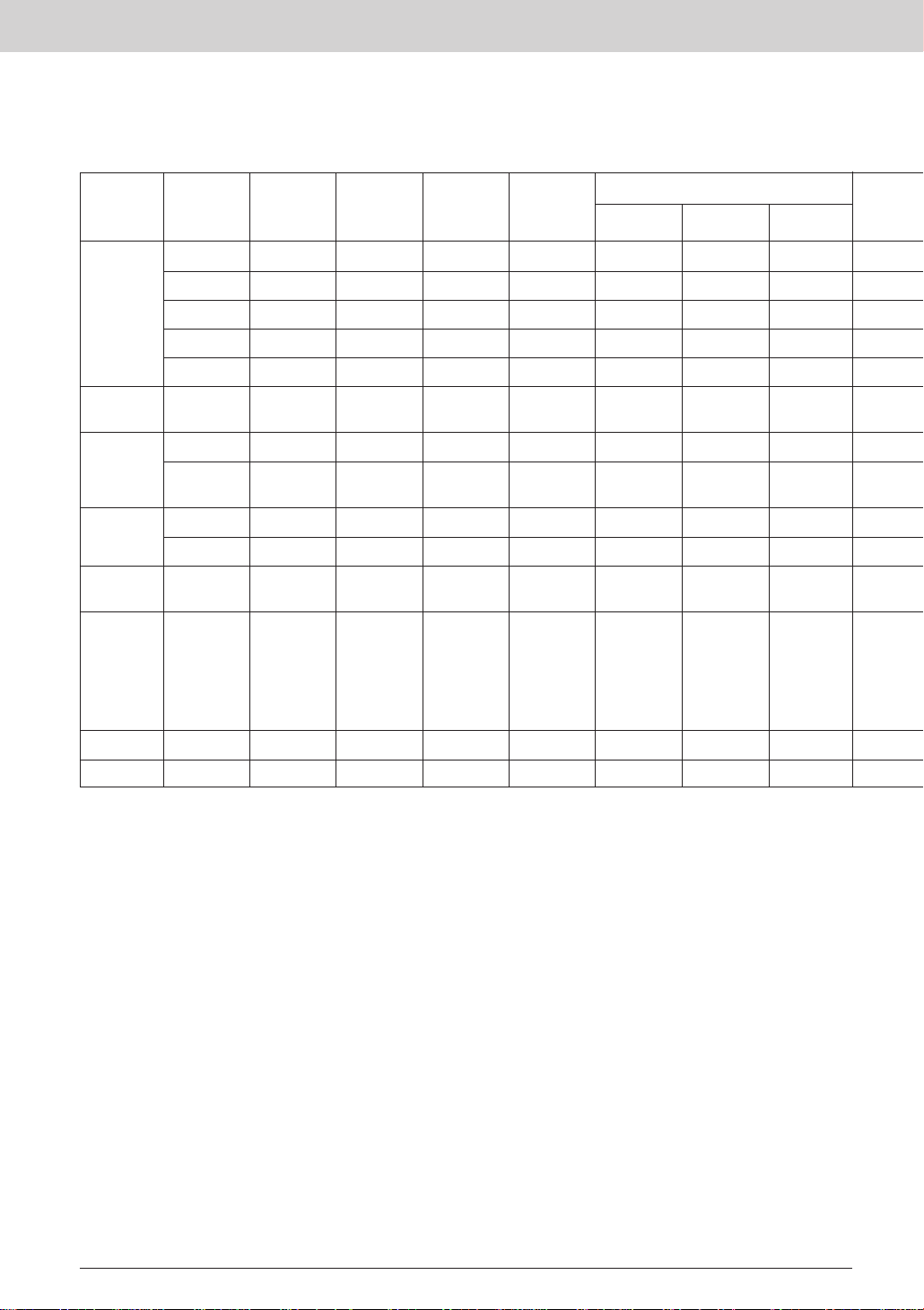
Routing Switcher Features
Signal type
HD SDI/SDI
video
SDI/SDTI
video***
Analog
composite
video
Routing
switcher type
HDS-X5800 264 x 272 ● 1056 x 272 1024 x 1024 ● ● ●
HDS-X3700 128 x 128 ● 1024 x 1024 ● ● ●(10BASE-T)
HDS-X3600 64 x 64 ● 1024 x 1024 ● ● ●(10BASE-T)
HDS-X3400 16 x 16 ● 1024 x 1024 ● ● ●(10BASE-T)
HKSP-061M 8 x 4 16 x 8 ●
BKPF-300 8 x 2 112 x 2 ●
BVS-V3232 32 x 32 512 x 512 ●
BKPF-301 8 x 2 32 x 2 ●
Matrix size Multi-level cascadable S-BUS matrix
Maximum Maximum Control
matrix size* size**
S-BUS
RS-422A
(CART)
Ethernet
(100BASE-TX)
With HKSP-300
Analog audio
AES/EBU
audio
Analog
composite
video,analog
audio and
AES/EBU
audio
RS-422A DVS-RS1616 16 x 16 ● 128 x 128 512 x 512 ●
Time code DVS-TC3232 32 x 32 ● 256 x 256 512 x 512 ●
Notes:
* An entry in the ‘Maximum cascadable matrix size’ column indicates that routers of this type can be cascaded to form larger matrix, up to the maximum shown.
Cascade sets are required.
** Maximum S-BUS matrix size that can be controlled from the primary station.
*** SDTI is defined as SMPTE305M.
HKSP-061M installs in PFV-SP Series Signal Processing Units.BKPF-300 Series boards install in PFV-D/PFV-HD Series Signal Processing Units.
BVS-A3232 32 x 32 512 x 512 ●
BKPF-351 8 x 2 32 x 2 ●
BKPF-350 8 x 2 112 x 2 ●
DVS-128 128 x 128 ● 1024 x 1024 ● ●
2
Page 5
Routing Switcher Reference Guide
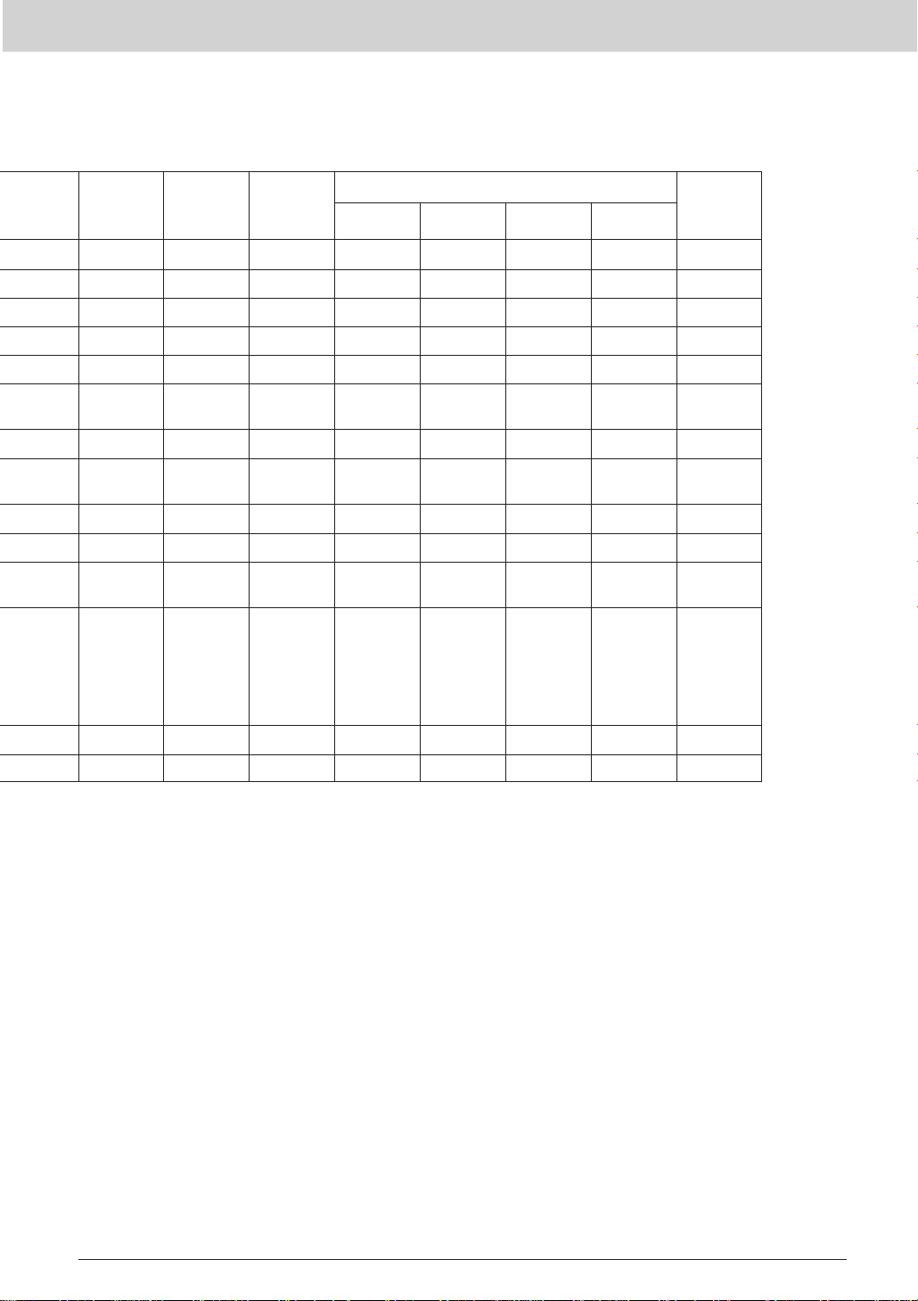
Backup Board option
Alarm output ISR support PSU/CPU
option
● Standard ● ● ● 22
● Standard Standard ● ● ● 8
● Standard Standard ● ● ● 4
Standard Standard ● ● ● 1
● BKDS-RS1690 3
● BKDS-RS1690 3
Monitor Input Output Matrix
Rack height
● BKDS-12890 Standard ● ● ● 14
BKDS-RS1690 ● 8
BKDS-RS1690 ● 8
3
Page 6
Routing Switcher Reference Guide
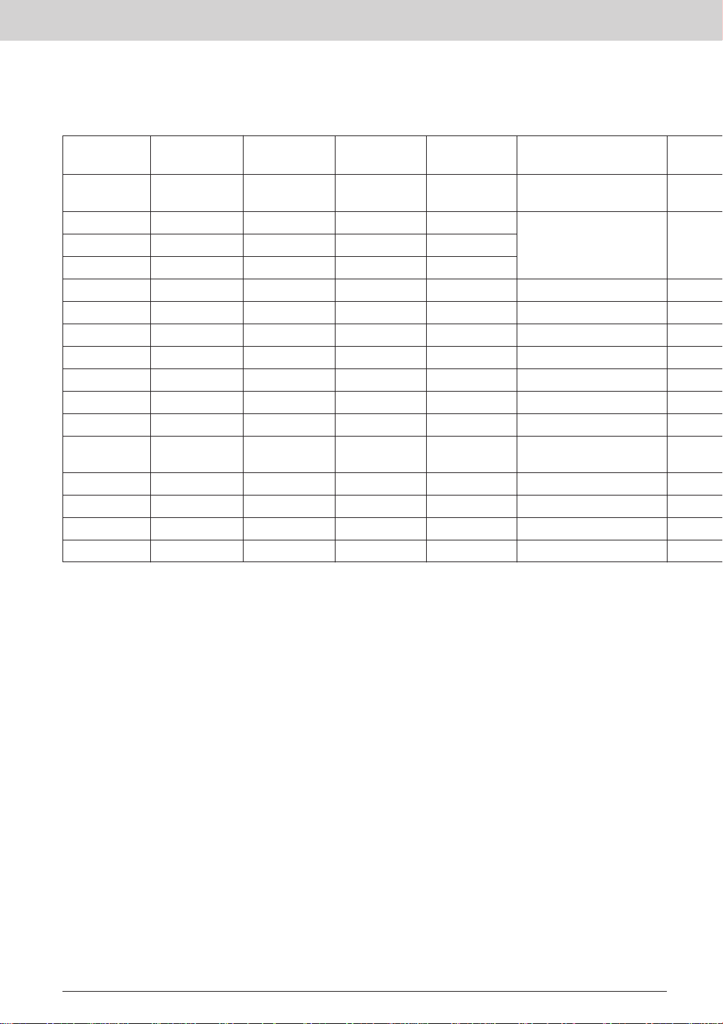
Routing Switcher Options
Routing switcher
type boards Supply Units
HDS-X5800 Standard Standard Standard
HDS-X3700 Standard Standard Standard
HDS-X3600 Standard Standard Standard
HDS-X3400 Standard
HKSP-061M
BKPF-300
BVS-V3232 BKDS-RS1690 BKDS-PV3291
BKPF-301
BVS-A3232 BKDS-RS1690 BKDS-PV3291
BKPF-351
BKPF-350
DVS-128 Standard Standard
DVS-RS1616 BKDS-RS1620 BKDS-RS1690 BKDS-RS1691
DVS-TC3232 BKDS-RS1620 BKDS-RS1690 BKDS-RS1691
HKSP-R80 HKSP-R81
BKPF-R70A BKPF-R70A
Cascade set
Backup CPU Backup Power
Monitoring output Input
HKS-5810M(HD/SD)
HKS-5810SD(SD)
HKDS-X3014(HD/SD)
HKDS-X3011(SD)
BKDS-AV10(Analog video)
BKDS-AA10(Analog audio)
4
Page 7
Routing Switcher Reference Guide
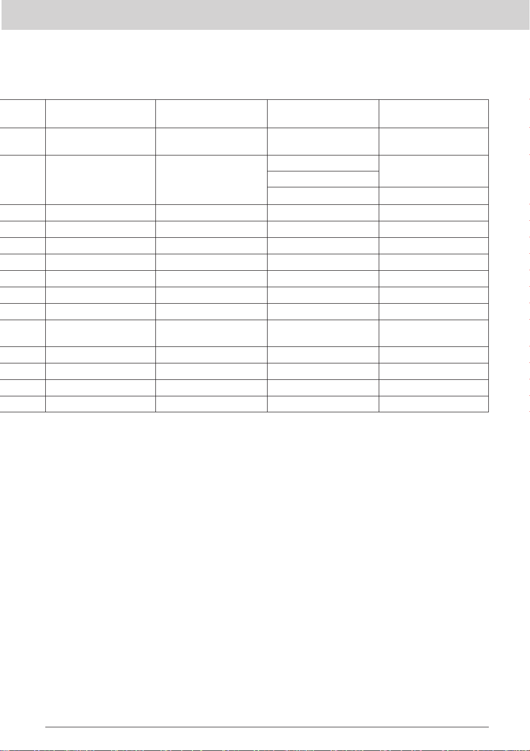
Distribution Output Input expansion Matrix
HKS-5820M(HD/SD)
HDS-X3010(HD/SD)
HKS-5860M(HD/SD) HKS-5811M(HD/SD) HKS-5830M(HD/SD)
HKS-5860SD(SD) HKS-5811SD(SD) HKS-5830SD(SD)
HKDS-X3064(HD/SD)
HKDS-X3051(SD)
BKDS-AV11(Analog video)
BKDS-AA11(Analog audio)
HKDS-X3060(HD/SD)
HKDS-X3050(SD)
Standard
5
Page 8

Routing Switcher Reference Guide
Backup CPU boards
Each type of backup CPU board is identical to the main CPU board it supports. If the main
CPU fails, the backup CPU automatically takes over all control functions and the router
continues to function normally.
HDS-X5800/X3700/X3600 video routing switchers incorporate a redundant CPU board as
standard. The HKSP-R80 routing switcher controller offers sophisticated primary station
functionality, and system redundancy with the HKSP-R81 backup CPU, to any routing
switcher system. The HDS-X5800/X3700/X3600 or HKSP-R80 provide full system
management of all up-loading and down-loading of configuration files from a PC running
BZR-2000 routing switcher control software via a 10/100Base-T Ethernet-based network.
Backup Power Supply Units
A routing switcher backup Power Supply Unit (PSU) is a valuable option in critical
applications, such as on-air play out systems. It operates in parallel with the main router
PSU so that, if this fails, the backup supply continues to supply DC power to the routing
switcher. AC power for the backup PSU is fed through a separate connector, so that the
main and backup units can be powered from different AC power sources.
6
Page 9
I/F Processor Functional Index
PFV-SP Series PFV-HD Series PFV-D Series PFV-L Series
Mounting frame PFV-SP3100 PFV-HD50A PFV-D50A
Backup power supply
SDI distribution amplifier BKPF-L611
SDI monitoring distribution amplifier BKPF-L613C
Video A to D converter HKPF-101 BKPF-L601C
Video D to A converter HKPF-102 BKPF-L602C
Audio/video multiplexer HKSP-105 HKPF-105M BKPF-205 BKPF-L605
Audio/video demultiplexer HKSP-106 HKSP-106M BKPF-206 BKPF-L606
4:2:2 to 4 fsc NTSC converter BKPF-012A
4 fsc to NTSC 4:2:2 converter BKPF-021
Digital video delay line HKSP-008HD
Line synchronizer HKSP-008HD BKPF-L608C
Frame synchronizer HKSP-008HD BKPF-L608C
Analog composite to 4:2:2 decoder BKPF-L641
4:2:2 to analog composite encoder
Analog video distribution amplifier BKPF-L703A
Video delay distribution amplifier BKPF-L723
Black burst regenerator BKPF-L704
AES/EBU distribution amplifier BKPF-L653
Audio distribution amplifier BKPF-L753A
Audio A to D converter BKPF-L751
Audio D to A converter BKPF-L752
Audio signal generator BKPF-L754
HD to 525 downconverter HKPF-525AV
525/625 to HD up-converter
HDCAM encoder HKPF-E270
HDCAM decoder HKPF-D270
Digital video 8 x 2 selector HKSP-061M BKPF-300
Analog video 8 x 2 selector BKPF-301
Digital audio 8 x 2 selector BKPF-350
Analog audio 8 x 1 selector BKPF-351
S-BUS expander/repeater BKPF-L803
Routing switcher controller
Optical to electrical converter HKPF-SP021
Electrical to optical converter HKSP-SP022
HD color corrector HKSP-313
HD/SD multi-format converter HKPF-9000
PFV-SP3300 PFV-HD300A PFV-D300 PFV-L10
PFV-D10
HK-PSU03 BKPF-PS300 BKPF-PS300 BKPS-LPS10
HK-PSU01 BKPF-PS50A BKPF-PS50A
HKPF-SP003 HKPF-103M BKPF-L603
BKPF-L612
BKPF-L632
BKPF-L642
HKSP-525 HKPF-525V
HKPF-9000
HKSP-1125 HKPF-1125A
HKPF-9000
HKSP-R80 BKPF-R70A
HKSP-R81
7
Page 10

I/F Processor Cross Reference Guide
NTSC/PAL YCbCr or RGB
BKPF-301
NTSC/PAL BKPF-L704A BKPF-L632
YCbCr or RGB
Component
serial digital
Output formats HKPF-SP003
Composite
serial digital
HD serial digital
HD-SDTI HKPF-E270
AES/EBU
digital audio
BKPF-L703A BKPF-L613C
(NTSC output) BKPF-L642
BKPF-L723
BKPF-L641 BKPF-L601 BKPF-206 HKPF-525AV
HKPF-1125A
HKSP-1125 HKSP-1125 HKPF-9000 HKPF-SP003
HKPF-101
Component Composite
serial digital serial digital
BKPF-152C
BKPF-L602C
BKPF-103
BKPF-104C
BKPF-105A
BKPF-106A
BKPF-107C
BKPF-108C
BKPF-111
BKPF-112
BKPF-113
BKPF-205 HKPF-525V
BKPF-300 HKSP-525
BKPFL603
BKPF-L605
BKPF-L606
BKPF-L608C
BKPF-L611
BKPF-L612
BKPF-L613C
HKSP-061M
BKPF-012A BKPF-L606 HKPF-9000
HKPF-1125A HKPF-1125A HKPF-9000
BKPF-L606 BKPF-L606 HKPF-106M
Input formats
BKPF-205
BKPF-206
BKPF-300
BKPF-L603
BKPF-L605
BKPF-L611
BKPF-L612
HKPF-SP003
HKPF-9000
HKSP-061M
HD serial digital
HKPF-102
HKPF-103M
HKPF-105M
HKPF-106M
HKSP-008HD
HKSP-061M
HKSP-313
Analog audio BKPF-206 BKPF-206
S-BUS control
Optical (SD SDI) HKPF-SP022 HKPF-SP022
Optical (HD SDI) HKPF-SP022
8
Page 11
I/F Processor Cross Reference Guide
HD-SDTI
AES/EBU
digital audio
BKPF-L605 BKPF-205 HKPF-SP021
BKPF-L605 BKPF-205 HKPF-SP021
Analog audio S-BUS control Ethernet control Optical (SD SDI) Optical (HD SDI)
HKPF-D270 HKPF-105M HKPF-SP021
HKPF-SP003 HKPF-SP021
HKPF-SP022
BKPF-350
BKPF-L653
BKPF-L752 BKPF-351
BKPF-L751
BKPF-L753A
BKPF-L754
(output only)
BKPF-L803
BKPF-R70A HKSP-R80
HKSP-R80 HKSP-R81
HKSP-R81
9
Page 12

10
Page 13

Routing Switchers
HDS-X5800. . . . . . . . . . . . . . 12
HDS-X3700. . . . . . . . . . . . . . 14
HDS-X3600. . . . . . . . . . . . . . 15
HDS-X3400. . . . . . . . . . . . . . 16
DVS-128 . . . . . . . . . . . . . . . . 17
DVS-RS1616. . . . . . . . . . . . . 19
DVS-TC3232. . . . . . . . . . . . . 20
BVS-A3232 . . . . . . . . . . . . . . 21
BVS-V3232 . . . . . . . . . . . . . . 22
BKS-R1617 . . . . . . . . . . . . . . 23
BKS-R1618 . . . . . . . . . . . . . . 24
BKS-R3216 . . . . . . . . . . . . . . 25
BKS-R3219 . . . . . . . . . . . . . . 26
BKS-R3220 . . . . . . . . . . . . . . 27
BKS-R3240A. . . . . . . . . . . . . 28
BKS-R3242A. . . . . . . . . . . . . 29
BKS-R3248A. . . . . . . . . . . . . 30
BKS-R3280 . . . . . . . . . . . . . . 31
BKS-R3281 . . . . . . . . . . . . . . 32
HKSP-R80. . . . . . . . . . . . . . . 33
BKPF-R70A . . . . . . . . . . . . . . 34
BKS-R5001 . . . . . . . . . . . . . . 35
BZR-2000 . . . . . . . . . . . . . . . 36
BZR-IF310. . . . . . . . . . . . . . . 37
Routing Switchers
11
Page 14
Routing Switchers
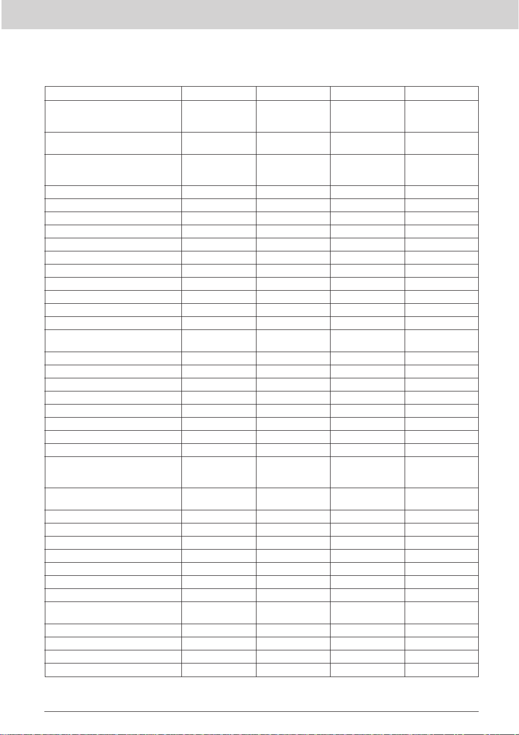
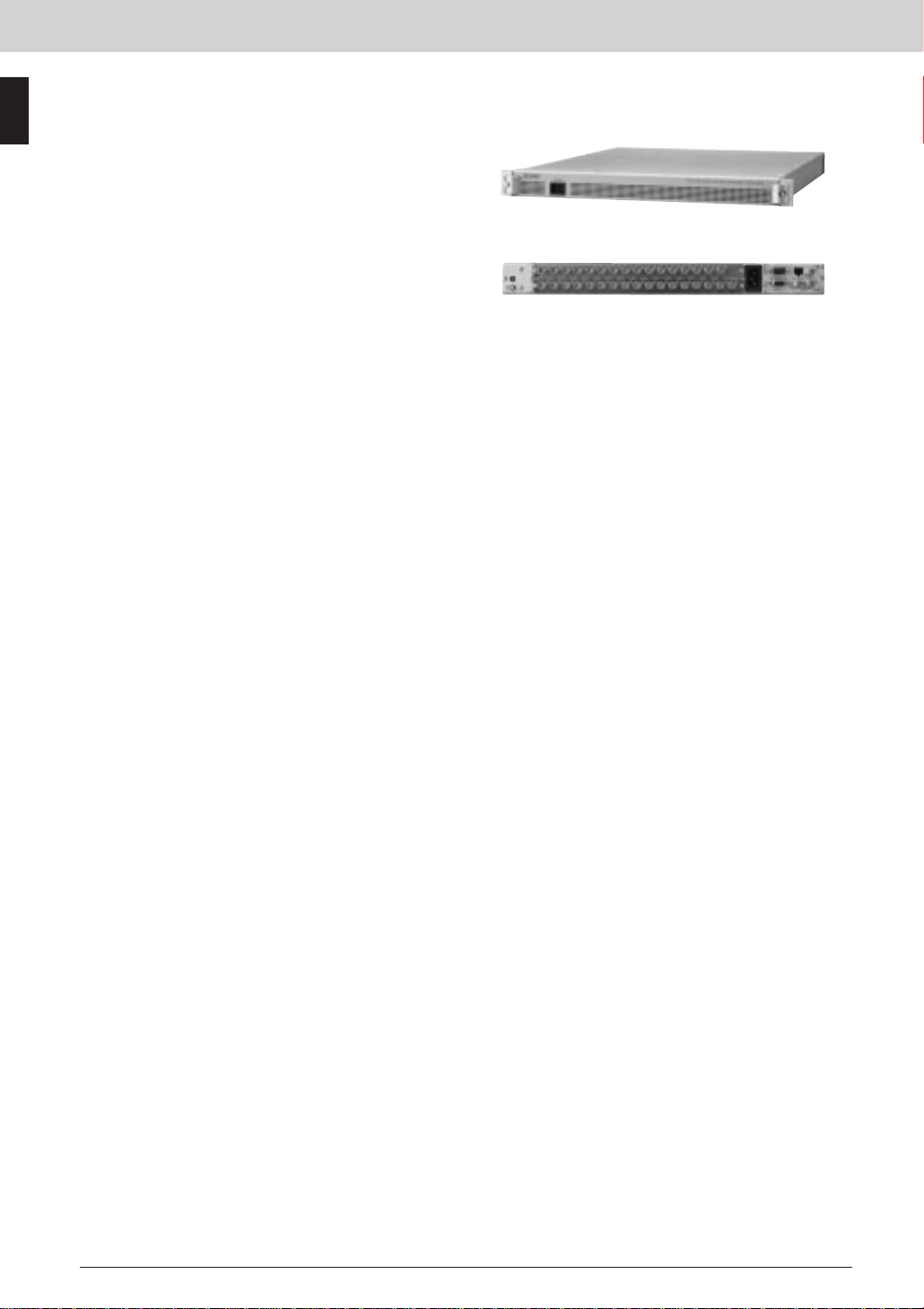
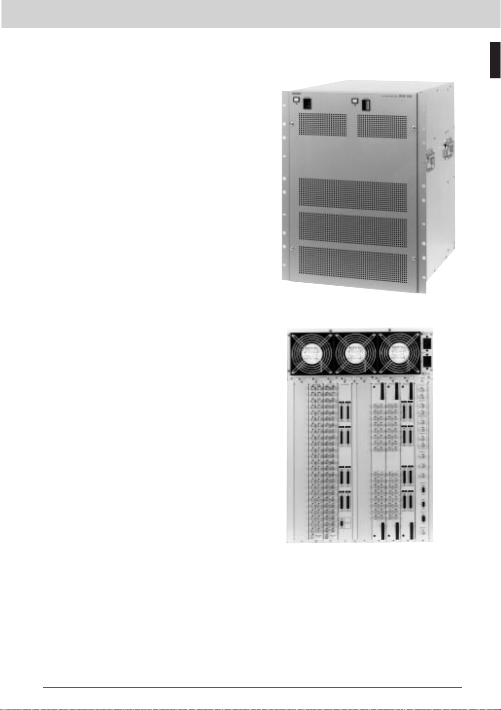
HDS-X5800 Multi Bit-Rate Routing Switcher
The HDS-X5800 is a large-scale, multi format and multi
bit-rate routing switcher for use in Sony S-BUS systems.
The HDS-X5800 can be expanded up to a maximum
matrix size of 1056 x 272. A range of I/O module handles
signals from 143 Mb/s to 1.5 Gb/s. Remote maintenance
and remote control routing functions are available via a
Routing Switchers
100 Base-TX network. Four reference inputs and four
simultaneous S-BUS control ports are included. The four
reference inputs support the co-existence of four different
vertical interval switching times. Black burst or tri-level
sync is available.The power consumption of a 264 x 272
HDS-X5800 is approx. 900 W including a redundant
power supply unit and control board.
Features
*Highly flexible, multi bit-rate routing switcher for use in
S-BUS systems *Compact size and high packing density
— 264 x 272 in 22RU *Flexible input and output
configurations — Increments of 33 inputs and/or 34
outputs; HD/SD input and output options; SD input and
output options *Non-blocking expansion up to 1056 x
1088 *143 Mb/s to 1.5 Gb/s in the same frame *Auto
cable equalization *Auto re-clocking at 143, 177, 270,
360, 540 Mb/s and 1.485 Gb/s — Re-clocks DVB-ASI
signals with an optional HKS-5810M/5820M/5830M/
5860M board installed *Robust and powerful Sony S-BUS
control system *Quad-standard operation in a single
frame — Four vertical interval switching references;Four
S-BUS control ports *Ethernet-based remote control and
set-up *Fully redundant internal controllers and power
supplies as standard *Front loading and hot swap
modules *Low power consumption (approx.900 W)
Supplied Accessories
Operation manual (1)
BZR-20 backup software (1)
BNC T-bridge connector (1)
75 Ω terminator (5)
Maintenance manual (1)
Installation manual (1)
Optional Boards
HKS-5810M HD/SD Input Board
HKS-5810SD SD Input Board
HKS-5811M HD/SD Cascade Input Board
HKS-5811SD SD Cascade Input Board
HKS-5820M HD/SD Input Distribution Board
HKS-5830M HD/SD Matrix Board
HKS-5830SD SD Matrix Board
HKS-5860M HD/SD Output Board
HKS-5860SD SD Output Board
Optional Software
BZR-2000 Routing Switcher Control Software
Optional Peripherals
BKS-R1617 Multi-Display Control Unit
BKS-R1618 Universal Control Unit
BKS-R3216 Multi-BUS Control Unit
BKS-R3219 Universal Control Unit
BKS-R3220 X-Y Control Unit
BKS-R3240A X-Y Control Unit
BKS-R3242A X-Y Control Unit
BKS-R3248A X-Y Control Unit
BKS-R3280 Single Status Display Unit
BKS-R3281 Single Status Display Unit
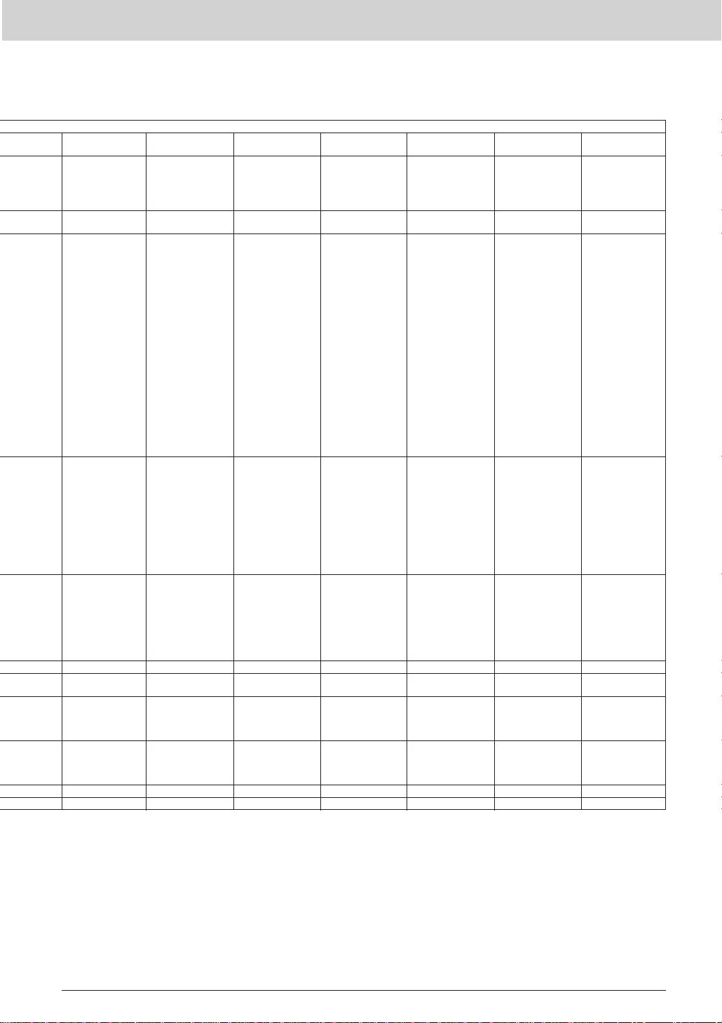
Rear Panel
12
Page 15

Routing Switchers
Specifications
Inputs/outputs
Serial digital input:
SDI IN connector (BNC type)
(up to 264 in steps of 33) 0.8 Vp-p
610%, 75 Ω
Channel coding:
Scrambled NRZI
Cable length
SD options:
200 m max. (With Belden 8281,
Fujikura 5C2V or equivalent coaxial
cable)
HD/SD options:
100 m max. (With Belden 1694A,
Fujikura 5CFB or equivalent coaxial
cable)
Input return loss
SD options:
15 dB or more (5 MHz to 360 MHz)
HD/SD options:
15 dB or more (5 MHz to 1.485 GHz)
Serial digital output:
SDI OUT connector (BNC type)
(Up to 272 in steps of 34)
Signal standard
SD options:
4:2:2 component serial digital signal
(SDI), conforming to
SMPTE259M-A/B/C/D
HD/SD options:
HD component serial digital signal
(HD SDI), conforming to SMPTE292M
Data transfer rate
SD options:
143 Mb/s to 360 Mb/s
HD/SD options:
143 Mb/s to 1.485 Gb/s
Re-clocking
SD options:
143, 177, 270, 360 Mb/s
HD/SD options:
143, 177, 270, 360, 540 Mb/s;
1.485/1.001, 1.485 Gb/s
Output return loss
SD options:
15 dB or more (5 MHz to 360 MHz)
HD/SD options:
15 dB or more (5 MHz to 1.485 GHz)
REMOTE 1
Connector:
BNC type (4)
Protocol:
Sony S-BUS
Data transfer rate:
312 kb/s (1250 kb/s will be
supported in the future)
Data transfer method:
Bi-phase Space
Cable length:
500 m max. (With Belden 8281,
Fujikura 5C2V or equivalent coaxial
cable)
REMOTE 2
Connector:
D-sub 9-pin (2), complies with
RS-422A signal standard
Protocol:
Sony Cart+
Data transfer rate:
38.4 kb/s
REMOTE 3
Connector:
D-sub 9-pin male (1), complies with
RS-232C signal standard, 38.4 Kb/s
DTR control, 8 bits, no parity, no
check, 1 stop bit
ALARM OUT:
Mini D-sub 9-pin female (4), Parallel
(relay contact outputs 6-ch)
REF IN:
BNC (4), with loop-through output,
tri-level sync or black burst signal
NETWORK:
RJ-45 (1), 100BASE-TX
General
Power requirements:
AC 100 V to 240 V, 50 to 60 Hz
Power consumption:
Approx. 900 W (fully loaded)
Operating temperature:
5 to 40 °C (41 to 104 °F)
Operational humidity:
10 to 90% (no condensation)
Dimensions (W x H x D)
440 x 974 x 520 mm
(17 3 /8 x 38 3 /8 x 20 1 /2 inches)
(Without projections)
Mass:
Approx. 90 kg (fully loaded) (198 lb)
Service parts: Extension Board EX-847 (Part No,
A-8329-772-A), Maintenance Manual Part II,
Protocol Manual
Routing Switchers
13
Page 16

Routing Switchers
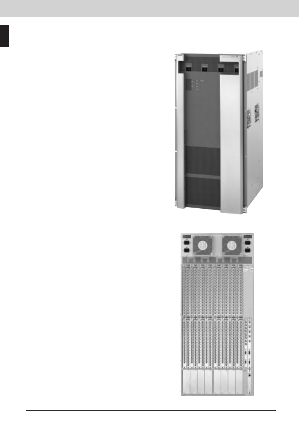
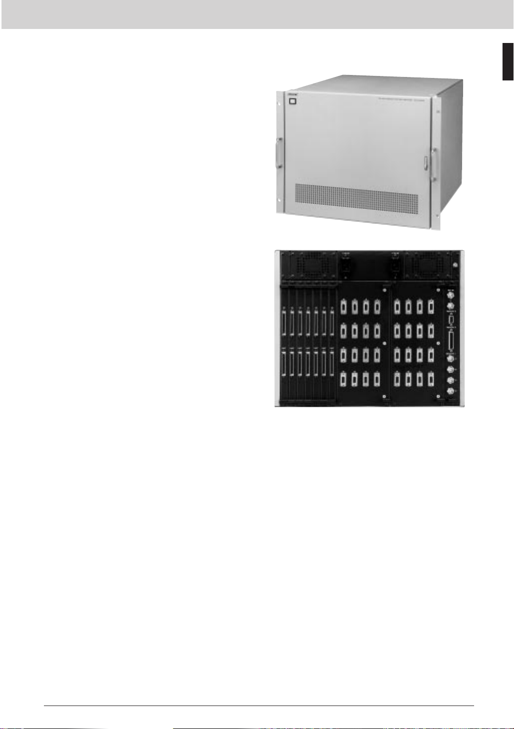
HDS-X3700 Multi Bit-Rate Routing Switchers
The HDS-X3000 Series are ultra-compact multi bit-rate
routers developed to support every format defined by Rec
ITU-R BT605, SMPTE259M (SD), and SMPTE292M (HD)
as well as 1080/24P format. A range of I/O modules
handles signals from 143 Mb/s up to 1.5 Gb/s. Router
control is via S-BUS and RS-422A. S-BUS is providing
Routing Switchers
communications and tally management with BKS-R
Series routing switcher control units, Sony MVS/DVS
Series production switchers and so on. Among the many
features that S-BUS supports are multi-level working,
signal breakaway, phantom operation of cross-points and
tie-line management. Router data is maintained in
memory by a 24-hour battery backup.
Features
* A range of highly flexible, multi bit-rate routing switchers
for use in S-BUS systems * High density, ultra compact
design * Up to 128 x 128 SD/HD I/O in 8U * 143 Mb/s to
1.5 Gb/s in the same frame, without any system alteration
* SDI (143, 177, 270, 360 Mb/s and 540 Mb/s) * SDTI
(270 Mb/s) * HD SDI (1.485 and 1.485/1.001 Gb/s) *
Flexible input and output configurations in increments of
16 channels * HD SDI/SD SDI input and output options *
Low-cost SD SDI input and output options * Auto cable
equalization on inputs and re-clocking on outputs *
Passes DVB-ASI signals * Supports SMPTE292M, which
includes the proposed 1080/24P format * Black burst and
tri-level sync reference switching in blocks of 32 outputs *
Monitoring outputs in blocks of 32 channels * S-BUS and
RS-422A control * Redundant control and power supply
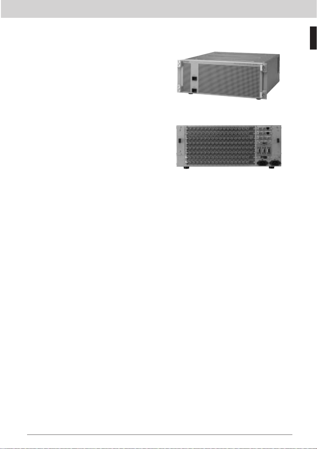
Rear Panel
Supplied Accessories
Operation manual (1)
Installation manual (1)
Maintenance manual (1)
75 Ω teminator (1)
BNC T-bridge connector (1)
Backup software BZR-20 (1)
Optional Accessories
RMM-10 Rack Mount Kit
Optional Boards
HKDS-X3010 Distribution Board
HKDS-X3011 SD Serial Input Board
HKDS-X3064 SD/HD Serial Output Board
HKDS-X3060 SD/HD Matrix Board
HKDS-X3051 SD Serial Output Board
HKDS-X3050 SD Matrix Board
HKDS-X3014 SD/HD Serial Input Board
Optional Software
BZR-2000 Routing Switcher Control Software
Optional Peripherals
BKS-R1617 Multi-Display Control Unit
BKS-R1618 Universal Control Unit
BKS-R3216 Multi-BUS Control Unit
BKS-R3219 Universal Control Unit
BKS-R3220 X-Y Control Unit
BKS-R3240A X-Y Control Unit
BKS-R3242A X-Y Control Unit
BKS-R3248A X-Y Control Unit
BKS-R3281 Single Status Display Unit
BKS-R3280 Single Status Display Unit
Specifications
Inputs/outputs
REMOTE 1:
S-BUS, BNC type (3)
Data transfer rate:
312 kb/s
Data transfer method:
BI-PHASE SPACE
Transmission distance:
500 m (with Belden 8281, Fujikura
5C2V or equivalent 75 Ω coaxial
cable). Isolator/Expander
Expandable to 1000 m with a
BKPF-L803 S-BUS Isolator/Expander
REMOTE 2:
Complies with RS-422A signal
standards
D-sub 9-pin (2)
Data transfer rate:
38.4 kb/s
Protocol:
Cart+
REMOTE 3:
Complies with RS-232C signal
standards
D-sub 9-pin male (1)
Terminal:
9.6/38.4 kb/s DTR control,
8 bits, no parity, 1 stop bit
REMOTE 4:
S-BUS, BNC type (1) for monitoring
Same specifications as REMOTE 1
ALARM OUT:
Parallel (relay) (2 connecting points)
Mini D-sub 15-pin female
REF IN:
Tri-level sync/Black burst:
BNC with loop-through (2)
NETWORK:
10Base-T, RJ-45 (2)
General
Power requirements:
100 to 240 V AC, 50/60 Hz
Power consumption:
650 W (128 x 128, 1.5 Gb/s)
Operational temperature:
5 to 40 °C (41 to 104 °F)
Operational humidity:
10 to 90%
Dimensions (W x H x D):
440 x 354 x 520 mm
(17 3/8 x 14 x 20 1/2 inches)
Mass:
Approx. 20 kg (44 lb 1 oz) (without
modules)
Service parts: Extension Board, Maintenance
Manual Part II, Protocol Manual
14
Page 17
Routing Switchers
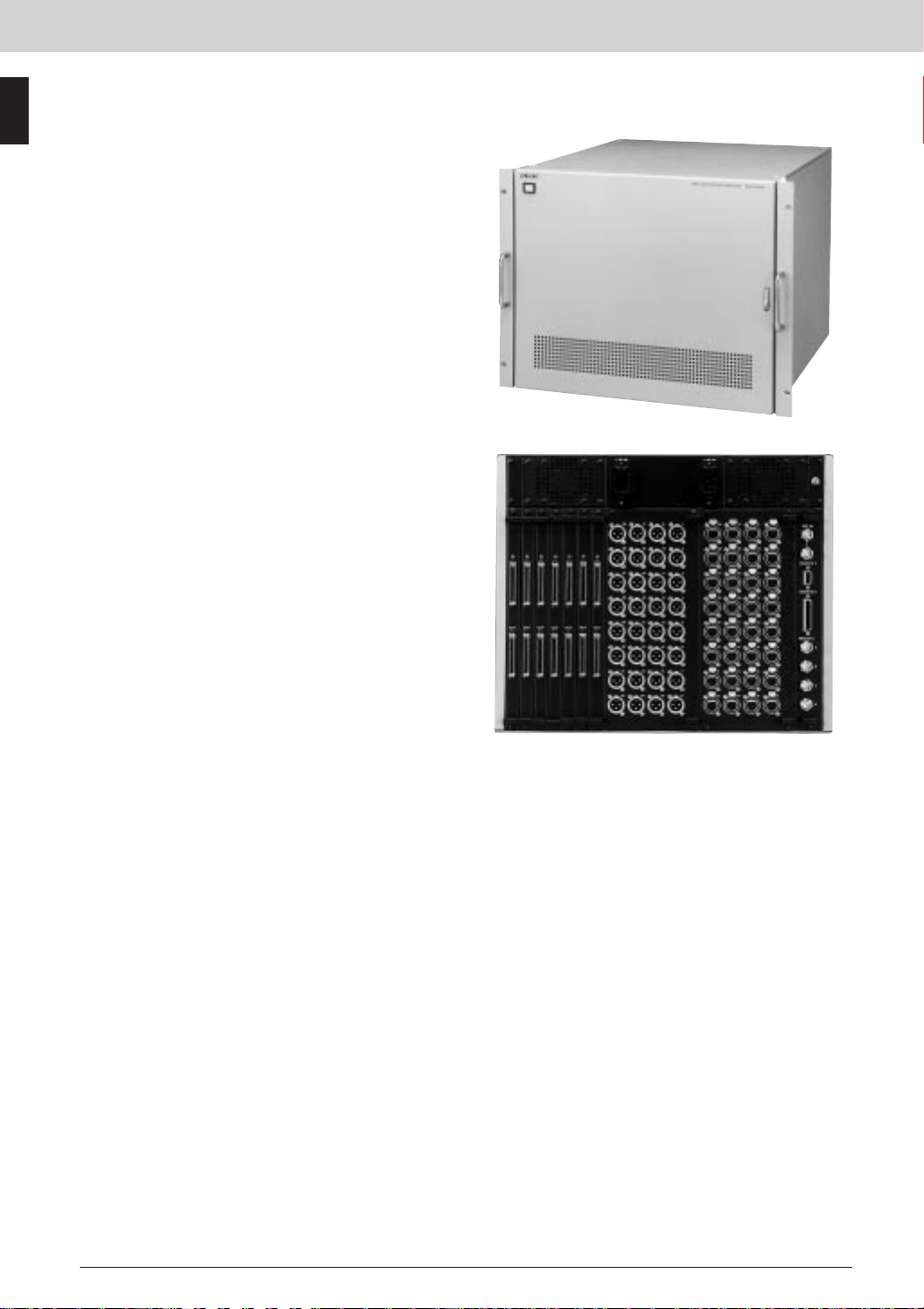
HDS-X3600 Multi Bit-Rate Routing Switchers
The HDS-X3000 Series are ultra-compact multi bit-rate
routers developed to support every format defined by Rec
ITU-R BT605, SMPTE259M (SD), and SMPTE292M (HD)
as well as 1080/24P format. A range of I/O modules
handles signals from 143 Mb/s up to 1.5 Gb/s. Router
control is via S-BUS and RS-422A. S-BUS is providing
communications and tally management with BKS-R
Series routing switcher control units, Sony MVS/DVS
Series production switchers and so on. Among the many
features that S-BUS supports are multi-level working,
signal breakaway, phantom operation of cross-points and
tie-line management. Router data is maintained in
memory by a 24-hour battery backup.
Features
* A range of highly flexible, multi bit-rate routing switchers
for use in S-BUS systems * High density, ultra compact
design * 143 Mb/s to 1.5 Gb/s in the same frame,
without any system alteration * SDI (143, 177, 270, 360
Mb/s and 540 Mb/s) * SDTI (270 Mb/s) * HD SDI (1.485
and 1.485/1.001 Gb/s) * Flexible input and output
configurations in increments of 16 channels * HD SDI/SD
SDI input and output options * Low-cost SD SDI input and
output options * Auto cable equalization on inputs and
re-clocking on outputs * Passes DVB-ASI signals *
Supports SMPTE292M, which includes the proposed
1080/24P format * Black burst and tri-level sync reference
switching in blocks of 32 outputs * Monitoring outputs in
blocks of 32 channels * S-BUS and RS-422A control *
Redundant control and power supply
Supplied Accessories
Operation manual (1)
Installation manual (1)
Maintenance manual (1)
75 Ω teminator (1)
BNC T-bridge connector (1)
Backup software BZR-20 (1)
Optional Accessories
RMM-10 Rack Mount Kit
Optional Boards
HKDS-X3010 Distribution Board
HKDS-X3011 SD Serial Input Board
HKDS-X3064 SD/HD Serial Output Board
HKDS-X3060 SD/HD Matrix Board
HKDS-X3051 SD Serial Output Board
HKDS-X3050 SD Matrix Board
HKDS-X3014 SD/HD Serial Input Board
Optional Software
BZR-2000 Routing Switcher Control Software
Optional Peripherals
BKS-R1617 Multi-Display Control Unit
BKS-R1618 Universal Control Unit
BKS-R3216 Multi-BUS Control Unit
BKS-R3219 Universal Control Unit
BKS-R3220 X-Y Control Unit
BKS-R3240A X-Y Control Unit
BKS-R3242A X-Y Control Unit
BKS-R3248A X-Y Control Unit
BKS-R3281 Single Status Display Unit
BKS-R3280 Single Status Display Unit
Specifications
Inputs/outputs
REMOTE 1:
S-BUS, BNC type (2)
Data transfer rate:
312 kb/s
Data transfer method:
BI-PHASE SPACE
Transmission distance:
500 m (with Belden 8281, Fujikura
5C2V or equivalent 75 Ω coaxial
cable).
Expandable to 1000 m with a
BKPF-L803 S-BUS Isolator/Expander
REMOTE 2:
Complies with RS-422A signal
standards
D-sub 9-pin (2)
Data transfer rate:
38.4 kb/s
Protocol:
Cart+
REMOTE 3:
Complies with RS-232C signal
standards
D-sub 9-pin male (1)
Terminal:
9.6/38.4 kb/s DTR control,
8 bits, no parity, 1 stop bit
REMOTE 4:
S-BUS, BNC type (1) for monitoring
Same specifications as REMOTE 1
Rear Panel
ALARM OUT:
Parallel (relay) (2 connecting points)
Mini D-sub 15-pin female
REF IN:
Tri-level sync/Black burst:
BNC with loop-through (2)
NETWORK:
10Base-T, RJ-45 (2)
General
Power requirements:
100 to 240 V AC, 50/60 Hz
Power consumption:
330 W (64 x 64, 1.5 Gb/s)
Operational temperature:
5 to 40 °C (41 to 104 °F)
Operational humidity:
10 to 90%
Dimensions (W x H x D):
440 x 176 x 520 mm
(17 3/8 x 7 x 20 1/2 inches)
Mass:
Approx. 15 kg (33lb 1 oz) (without
modules)
Service parts: Extension Board, Maintenance
Manual Part II, Protocol Manual
Routing Switchers
15
Page 18
Routing Switchers
HDS-X3400 Multi Bit-Rate Routing Switchers
The HDS-X3000 Series are ultra-compact multi bit-rate
routers developed to support every format defined by Rec
ITU-R BT605, SMPTE259M (SD), and SMPTE292M (HD)
as well as 1080/24P format. A range of I/O modules
handles signals from 143 Mb/s up to 1.5 Gb/s. Router
control is via S-BUS and RS-422A. S-BUS is providing
Routing Switchers
communications and tally management with BKS-R
Series routing switcher control units, Sony MVS/DVS
Series production switchers and so on. Among the many
features that S-BUS supports are multi-level working,
signal breakaway, phantom operation of cross-points and
tie-line management. Router data is maintained in
memory by a 24-hour battery backup.
Features
* A range of highly flexible, multi bit-rate routing switchers
for use in S-BUS systems * High density, ultra compact
design * 143 Mb/s to 1.5 Gb/s in the same frame, without
any system alteration * SDI (143, 177, 270, 360 Mb/s and
540 Mb/s) * SDTI (270 Mb/s) * HD SDI (1.485 and
1.485/1.001 Gb/s) * Flexible input and output
configurations in increments of 16 channels * HD SDI/SD
SDI input and output options * Low-cost SD SDI input and
output options * Auto cable equalization on inputs and
re-clocking on outputs * Passes DVB-ASI signals *
Supports SMPTE292M, which includes the proposed
1080/24P format * Black burst and tri-level sync reference
switching in blocks of 32 outputs * Monitoring outputs in
blocks of 32 channels * S-BUS and RS-422A control *
Redundant control and power supply
Supplied Accessories
Operation manual (1)
Installation manual (1)
Maintenance manual (1)
75 Ω teminator (1)
BNC T-bridge connector (1)
Backup software BZR-20 (1)
Optional Accessories
RMM-10 Rack Mount Kit
Optional Boards
HKDS-X3010 Distribution Board
HKDS-X3011 SD Serial Input Board
HKDS-X3064 SD/HD Serial Output Board
HKDS-X3060 SD/HD Matrix Board
HKDS-X3051 SD Serial Output Board
HKDS-X3050 SD Matrix Board
HKDS-X3014 SD/HD Serial Input Board
Optional Software
BZR-2000 Routing Switcher Control Software
Optional Peripherals
BKS-R1617 Multi-Display Control Unit
BKS-R1618 Universal Control Unit
BKS-R3216 Multi-BUS Control Unit
BKS-R3219 Universal Control Unit
BKS-R3220 X-Y Control Unit
BKS-R3240A X-Y Control Unit
BKS-R3242A X-Y Control Unit
BKS-R3248A X-Y Control Unit
BKS-R3400 Routing Switcher Control Panel
BKS-R3281 Single Status Display Unit
BKS-R3280 Single Status Display Unit
Specifications
Inputs/outputs
REMOTE 1:
S-BUS, BNC type (1)
Data transfer rate:
312 kb/s
Data transfer method:
BI-PHASE SPACE
Transmission distance:
500 m (with Belden 8281, Fujikura
5C2V or equivalent 75 Ω coaxial
cable).
Expandable to 1000 m with a
BKPF-L803 S-BUS Isolator/Expander
REMOTE 2:
Complies with RS-422A signal
standards
D-sub 9-pin (1)
Data transfer rate:
38.4 kb/s
Protocol:
Cart+
REMOTE 3:
Complies with RS-232C signal
standards
D-sub 9-pin male (1)
Terminal:
9.6/38.4 kb/s DTR control,
8 bits, no parity, 1 stop bit
REF IN:
Tri-level sync/Black burst:
BNC with loop-through (1)
Rear Panel
NETWORK:
10Base-T, RJ-45 (1)
General
Power requirements:
100 to 240 V AC, 50/60 Hz
Power consumption:
70 W (16 x 16, 1.5 Gb/s)
Operational temperature:
5 to 40 °C (41 to 104 °F)
Operational humidity:
10 to 90%
Dimensions (W x H x D):
440 x 43.6 x 520 mm
(17 3/8 x 1 3/4 x 20 1/2 inches)
Mass:
Approx. 8.5 kg (18 lb 12 oz) (without
modules)
Service parts: Extension Board, Maintenance
Manual Part II, Protocol Manual
16
Page 19
Routing Switchers
DVS-128 Routing Switcher
The DVS-128 is a compact 128 inputs and 128 outputs
routing switcher capable of switching analog video, analog
audio and digital audio signals at the same time. It can
convert an analog audio input into a digital audio output,
and vice versa. Installation of up to four 32-input blocks
and four 32-output blocks is allowed. Input and output
blocks for analog video, analog audio and digital audio are
available. Video and audio blocks can be installed
together for married or unmarried A/V switching.
Features
* Matrix size up to 128 x 128 * Handles analog video,
AES/EBU audio and analog audio in blocks of 32 inputs
and 32 outputs to form square or rectangular matrix *
Typical audio matr ix configuration — I/O 1-32 analog
audio in to AES/EBU audio out; I/O 33-64 AES/EBU audio
in to analog audio out; I/O 65-96 AES/EBU audio; I/O
97-128 analog audio * Dual references of 525 and 625
allow simultaneous 2-standard vertical interval switching
of 60, 59.94 and 50 Hz in blocks of 32 outputs *
Monitoring outputs in blocks of 32 channels.* All plug-in
function boards can be hot-swapped for operational
convenience * Each signal type can be mapped into
S-BUS space of either 1024 x 1024 with 8 levels, or 1024
x 512 with 16 levels * Up to 2048 Description Names
registered in eight alphanumeric characters * 32 name
types selectable * Unlimited element groups in tie-line
management * Mounts in a 19-inch rack, 14U high
Routing Switchers
Supplied Accessories
Operation manual (1)
Installation manual (1)
Maintenance manual part 1 (1)
75 Ω terminator (3)
T-bridge (1)
Unit (1)
Optional Accessories
RMM-18DV Rack Slide Kit
RCC-G cables 9-pin/9-pin Cable
Optional Boards
BKDS-AA10 Analog Audio Input Board with
32 channels
BKDS-AA11 Analog Audio Output Board with
32 channels
BKDS-AV10 Analog Video Input Board with 32
channels
BKDS-AV11 Analog Video Output Board with
32 channels
BKDS-DA10 AES/EBU Input Board with 32
channels
BKDS-DA11 AES/EBU Output Board with 32
channels
Optional Software
BZR-2000 Routing Switcher Control Software
Rear Panel
Optional Peripherals
BKS-R1617 Multi-Display Control Unit
BKS-R1618 Universal Control Unit
BKS-R3216 Multi-BUS Control Unit
BKS-R3219 Universal Control Unit
BKS-R3220 X-Y Control Unit
BKS-R3240A X-Y Control Unit
BKS-R3242A X-Y Control Unit
BKS-R3248A X-Y Control Unit
BKS-R3280 Single Status Display Unit
BKS-R3281 Single Status Display Unit
17
Page 20

Routing Switchers
Specifications
Control
REMOTE 1:
REMOTE 2:
Routing Switchers
REMOTE 3:
REMOTE 4:
Video connectors:
Inputs return loss:
Clamping:
Frequency response:
DG:
DP:
Signal to noise ratio:
Crosstalk:
Analog audio
Inputs connector:
Inputs impedance:
Max inputs level:
Converter:
Frequency response:
Distortion:
Signal to noise ratio:
Crosstalk:
Converter:
Maximum output level:
Output impedance:
Output connector:
AES / EBU digital audio
Inputs connector:
Standard S-BUS
Connector type: BNC type (3)
Protocol: S-BUS
Transfer speed: 312 kb/s/1250 kb/s
RS-422A
Connector type: D-sub 9-pin female (2)
Protocol: Sony CART+ protocol
Transfer speed: 38.4 kb/s
RS-232C
Connector type: D-sub 9-pin male (1)
Protocol: Terminal/ISR/Data Backup
Transfer speed: 9600 b/s/38.4 kb/s
Monitor S-BUS
Connector type: BNC (1)
Protocol: S-BUS
Transfer speed: 312 kb/s
BNC type
More than 40 dB DC to 5 MHz
Pedestal clamping or DC coupled
100 kHz to 10 MHz, +/-0.15 dB
10 MHz to 30 MHz, +0.5/-1.0 dB,
Less than 0.1%
Less than 0.1 °
More than 73 dB at 5 MHz
Less than -60 dB at 5 MHz
D-sub 25-pin w/stereo 4 channels by 1
connector
20 kΩ /600 Ω internally selectable
+24 dBm, balanced
ADC 48 kHz/20 bits, Linear, AES/EBU
digital audio
20 Hz to 20 kHz, +0.2/-0.3
0.05% or less (1 kHz, reference level,
30 kHz low pass filter)
More than 90 dB (30 kHz low pass filter)
Less than -90 dB to 15 kHz
DAC 48 kHz/20 bits
+24 dBm into 600 Ω balanced.
Approx. 20 Ω
D-sub 25-pin w/stereo 4 channels by 1
connector
BNC type
Signal standards:
AES/EBU specification
75 Ω, unbalanced
SMPTE276M-1995
Television-Transmission of AES/EBU
digital audio signals over coaxial cable
Inputs signal level:
1 Vp-p
Max inputs cable length:
600 m max. (When using a Belden
8281, Fujikura 5C2V or equivalent
coaxial cable)
Reference:
Word sync and analog video signal
Outputs connector:
BNC type
General
Power requirements:
100 to 240 V AC, 50/60 Hz
Power consumption:
600 VA max.
Dimensions (W x H x D):
424 x 620 x 550 mm
(16 3/4 x 24 1/2 x 21 3/4 inches)
Mass:
Approx. 40 kg (88.18 lb)
Service parts: Extension board EX-717 (Part No.
A-8323-641-A), Extension board EX-681
(A-8323-641), Maintenance manual Part II,
Protocol Manual
18
Page 21
Routing Switchers
DVS-RS1616 RS-422A Remote Routing Switcher
The DVS-RS1616 is a 16 inputs and 16 outputs routing
switcher for RS-422A control signals. It can also operate
as a 32-port bi-directional router for master/slave
applications. Router control is by S-BUS and RS-422A.
S-BUS is a highly sophisticated system, providing
communication and tally management with BKS-R Series
routing switcher control units, Sony DVS Series video
switchers and so on. S-BUS also interfaces with
third-party equipment. Among the many features that
S-BUS provides are multi-level working, signal breakaway,
phantom operation of crosspoints and tie-line
management. Multiple DVS-RS1616 units, fitted with
cascade kits, can be connected to form a single matrix as
large as 256 x 256. An RS-232C port provides a PC
interface for router set up. Router data is maintained in
memory by a 24-hour battery backup.The DVS-RS1616
mounts in a standard 19-inch rack and is 8U high.
Features
* 16 x 16 switching matrix for RS-422A control signals *
Expandable to provide a maximum matrix size of 256 x
256 * S-BUS and RS-422A control * Backup power supply
and CPU options
Routing Switchers
Supplied Accessories
AC power cord (for U.S.A and Canada) (1)
AC power cord (for Europe and U.K.) (1)
AC plug adaptor (1)
75 Ω terminators (4)
T-bridge (1)
Plug holder B (black) (1)
Plug holder B (gray) (1)
Operation manual (1)
Maintenance manual (1)
Installation manual (1)
Optional Accessories
RCC-G cables 9-pin/9-pin Cable
RMM-30 Rack Mount Rail
Optional Boards
BKDS-RS1690 Backup Control Board
Optional Peripherals
BKS-R1608 Universal Control Unit
BKS-R1617 Multi-Display Control Unit
BKS-R1618 Universal Control Unit
BKS-R3216 Multi-BUS Control Unit
BKS-R3219 Universal Control Unit
BKS-R3220 X-Y Control Unit
BKS-R3240A X-Y Control Unit
BKS-R3242A X-Y Control Unit
BKS-R3248A X-Y Control Unit
BKDS-RS1691 Backup Power Supply
Specifications
Inputs/outputs
RS-422A input output:
9-pin, complying to RS-422A standards
Reference video signal inputs:
REF IN connectors (BNC type) (2), high
impedance, analog video, one is for
loop-through connection
Cascade inputs:
CASCADE IN (BKDS-RS1620) 1.27 mm
pitch connectors (68-pin type) (7)
Cascade outputs:
CASCADE OUT (BKDS-RS1620) 1.27
mm pitch connectors (68-pin type) (7)
AC power inputs:
3-pin AC connectors (2)
Remote control connectors
REMOTE 1:
S-BUS (BNC type) (4), 47 kΩ input
Data transfer method: BI-PHASE SPACE
Data transfer rate: 312.5 kb/s
Cable length: 500 m max. (when using
a Belden 8281, Fujikura 5C2V or
equivalent coaxial cable)
Checksum: HDLC CRC-CCIT
x 16 + x 12 + x 5 + 1
Rear Panel
REMOTE 2:
Complying with RS-422A signal
standards
D-sub 9-pin (1), 100 Ω/10 kΩ
Data transfer rate: 38.4 kb/s
REMOTE 3:
Complying with RS-232C standard
D-sub 25-pin (1), 9600 b/s, DTR control
8-bit, no parity, no check, 1 stop bit
General
Power requirements:
100 to 240 V AC, 50/60 Hz
1.3 to 0.8 A
Power consumption:
70 W
Operating temperature:
5 to 40 °C (41 to 104 °F)
Storage temperature:
-20 to 60 °C (-4 to 140 °F)
Dimensions (W x H x D):
482 x 354.4 x 450 mm
(19 x 14 x 17 3/4 inches)
(Excluding projecting parts)
Mass:
Approx. 25 kg (55 lb 2 oz)
19
Page 22
Routing Switchers
DVS-TC3232 Time Code Routing Switcher
The DVS-TC3232 is a 32 inputs and 32 outputs routing
switcher for 32 time code signals.Router control is by
S-BUS and RS-422A. S-BUS is a highly sophisticated
system, providing communication and tally management
with BKS-R Series routing switcher control units, Sony
DVS Series video switchers and so on. S-BUS also
Routing Switchers
interfaces with third-party equipment. Among the many
features that S-BUS supports are multi-level working,
signal breakaway, phantom operation of crosspoints and
tie-line management. Multiple DVS-TC3232 units, fitted
with cascade kits, can be connected to form a single
matrix as large as 256 x 256.An RS-232C port provides a
PC interface. Router data is maintained in memory by a
24-hour battery backup.The DVS-TC3232 mounts in a
standard 19-inch rack and is 8U high.
Features
* 32 x 32 switching matrix for time code signals *
Expandable to provide a maximum matrix size of 256 x
256 * S-BUS and RS-422A control * Backup power supply
and CPU options
Supplied Accessories
AC power cord (for U.S.A and Canada) (1)
AC power cord (for Europe and U.K.) (1)
AC plug adaptor (1)
75 Ω terminators (4)
T bridge (1)
Plug holder B (black) (1)
Plug holder B (gray) (1)
Operation manual (1)
Maintenance manual (1)
Installation manual (1)
Optional Boards
BKDS-RS1690 Backup Control Board
Optional Peripherals
BKS-R1608 Universal Control Unit
BKS-R1617 Multi-Display Control Unit
BKS-R1618 Universal Control Unit
BKS-R3216 Multi-BUS Control Unit
BKS-R3219 Universal Control Unit
BKS-R3220 X-Y Control Unit
BKS-R3240A X-Y Control Unit
BKS-R3242A X-Y Control Unit
BKS-R3248A X-Y Control Unit
BKDS-RS1620 Cascade Set
BKDS-RS1691 Backup Power Supply
RCC-R cables Cascade Connection Cable
RCC-G cables 9-pin/9-pin Cable
RMM-30 Rack Mount Rail
Specifications
Inputs/outputs
Time code inputs:
XLR 3-pin, female connectors (32)
Time code outputs:
XLR 4-pin, male connectors (32)
Reference video signal inputs:
REF IN connectors (BNC type) (2), high
impedance, analog video, one is for
loop-through connection
Cascade inputs:
CASCADE IN (BKDS-RS1620) 1.27 mm
pitch connectors (68-pin type) (7)
Cascade outputs:
CASCADE OUT (BKDS-RS1620) 1.27
mm pitch connectors (68-pin type) (7)
AC power inputs:
3-pin AC connectors (2)
Remote control connectors
REMOTE 1:
S-BUS (BNC type) (4), 47 kΩ input
Data transfer method: BI-PHASE SPACE
Data transfer rate: 312.5 kb/s
Cable length: 500 m max. (When using
a Belden 8281, Fujikura 5C2V or
equivalent coaxial cable)
Checksum: HDLC CRC-CCIT
x 16 + x 12 + x 5 + 1
Rear Panel
REMOTE 2:
Complying with RS-422A signal
standards
D-sub 9-pin (1), 100 Ω/10 kΩ
Data transfer rate: 38.4 kb/s
REMOTE 3:
Complying with RS-232C standard for
terminal correction
D-sub 25-pin (1)
9600 b/s, DTR control
8-bit, No parity, No check, 1 stop bit
General
Power requirements:
100 to 240 V AC, 50/60 Hz
1.3 to 0.8 A
Power consumption:
70 W
Operating temperature:
5 to 40 °C (41 to 104 °F)
Storage temperature:
-20 to 60 °C (-4 to 140 °F)
Dimensions (W x H x D)
482 x 354.4 x 450 mm
(19 x 14 x 17 3/4 inches)
(Excluding projecting parts)
Mass:
Approx. 25 kg (55 lb 2 oz)
20
Page 23
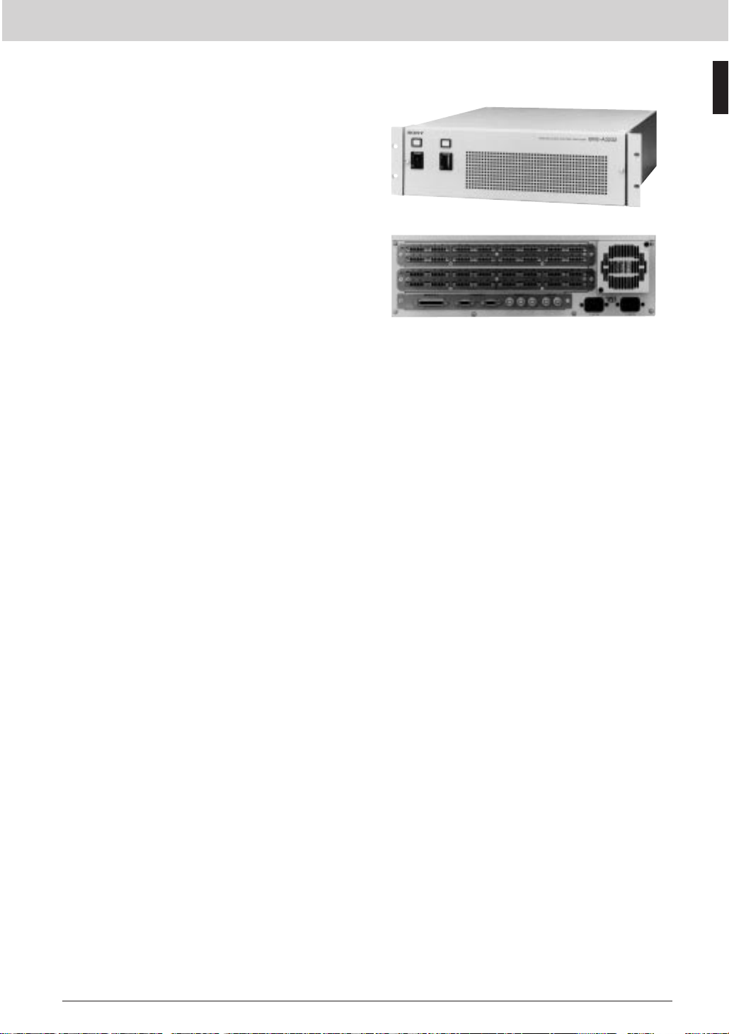
Routing Switchers
BVS-A3232 Analog Audio Routing Switcher
The BVS-A3232 is a 32 inputs and 32 outputs routing
switcher for analog audio signals.It can also operate as
16 x 16 two-channel switcher for stereo applications.
Router control is by S-BUS and RS-422A. S-BUS is a
highly sophisticated system, providing communication and
tally management with BKS-R Series routing switcher
control units, Sony DVS Series video switchers and so on.
S-BUS also interfaces with third-party equipment. Among
the many features that S-BUS supports are multi-level
working, signal breakaway, phantom operation of
crosspoints and tie-line management. An RS-232C port
provides a PC interface.Router data is maintained in
memory by a 24-hour battery backup.The BVS-A3232
mounts into a standard 19-inch rack and is 3U high.
Routing Switchers
Features
* 32 x 32 switching matrix for analog audio signals *
Transformer I/O * S-BUS and RS-422A control * Backup
power supply and CPU options
Supplied Accessories
Operation manual (1)
Installation manual (1)
Maintenance manual (1)
75 Ω terminators (3)
T-bridge (B) (1)
D-sub connector screws (2)
Audio connectors (32)
Optional Accessories
RCC-G cables 9-pin/9-pin Cable
RMM-30 Rack Mount Rail
Optional Peripherals
BKS-R1608 Universal Control Unit
BKS-R1617 Multi-Display Control Unit
BKS-R1618 Universal Control Unit
BKS-R3216 Multi-BUS Control Unit
BKS-R3219 Universal Control Unit
BKS-R3220 X-Y Control Unit
BKS-R3240A X-Y Control Unit
BKS-R3242A X-Y Control Unit
BKS-R3248A X-Y Control Unit
BKS-R3280 Single Status Display Unit
BKS-R3281 Single Status Display Unit
Specifications
Inputs/outputs —
Reference video signal inputs:
REF IN connectors (BNC type) (2), high
impedance, analog audio signal, with
loop-through output
Remote control connectors
REMOTE 1 A, B, C:
S-BUS (BNC type) (4), 47 kΩ input
Data transfer method: BI-PHASE
SPACE
Data transfer rate: 312.5 kb/s
Cable length: 500 m max. (When
using a Belden 8281, Fujikura 5C2V
or equivalent coaxial cable )
Checksum: HDLC CRC-CCIT
x 16 + x 12 + x 5 + 1
REMOTE 2:
Complies with RS-422A signal
standard with loop-through output
D-sub 9-pin (2), 100 Ω/10 kΩ
Data transfer rate: 38.4 kb/s
REMOTE 3:
Complies with RS-232C signal
standard for connecting a terminal
D-sub 25-pin
(Fixed with M2.6 screws) (1)
Terminal:
9600 b/s, DTR control, 8-bit, no parity,
no check, 1 stop bit
ISR:
9600 b/s, 7-bit, ODD parity, 1 stop bit
AC power input:
3-pin AC IN connectors (2)
Audio signals
Audio signal inputs:
6-pin connector (16) for 32 inputs
Audio signal outputs:
6-pin connector (16) for 32 outputs
Input impedance:
100 kΩ/600 Ω (selectable)
Standard input/output level:
+4 dBm
Maximum input level:
+24 dBm
Maximum output level:
+24 dBm (600 Ω load, balanced)
Frequency response:
60.1 dB
(20 kHz to 20 kHz, 1 kHz+4 dBm)
Distortion:
0.01% (20 Hz to 20 kHz, with +24 dBm
output)
Crosstalk:
Less than -80 dB (20 Hz to 20 kHz, with
+24 dBm output)
Signal-to-noise ratio:
More than 85 dB
(30 kHz LPF, nominal)
General
Power requirements:
100 to 240 V AC, 50/60 Hz
Current consumption:
1.2 to 0.6 A
(With all optional boards installed)
Operating temperature:
5 to 40 °C (41 to 104 °F)
Rear Panel
Dimensions (W x H x D):
424 x 132 x 500 mm
(16 3/4 x 5 1/4 x 19 3/4 inches)
Mass:
Approx. 16 kg (35 lb 4 oz)
(With all optional boards installed)
21
Page 24
Routing Switchers
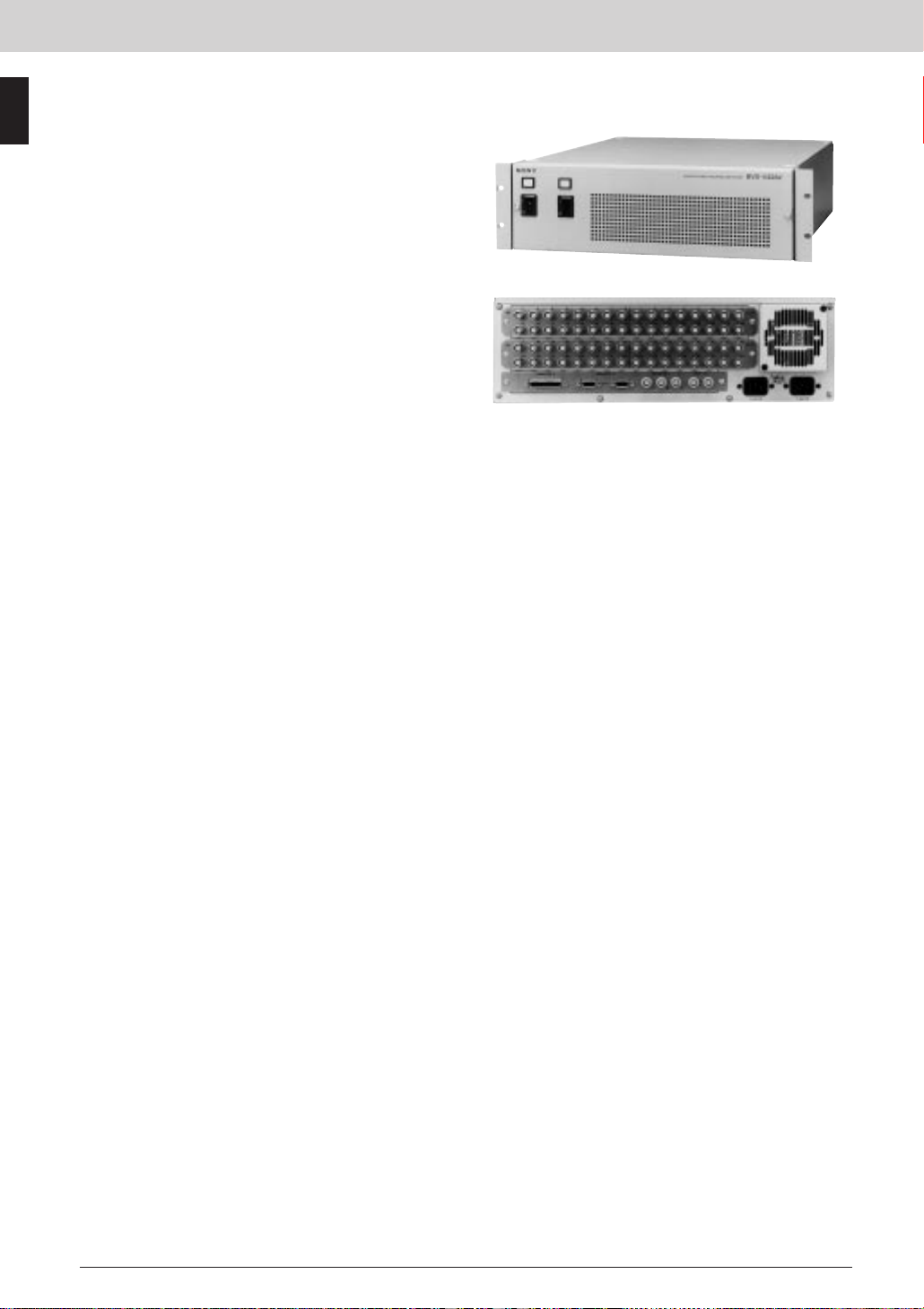
BVS-V3232 Analog Video Routing Switcher
The BVS-V3232 is a 32 inputs and 32 outputs routing
switcher for NTSC/PAL composite analog video signals.
Router control is by S-BUS and RS-422A. S-BUS is a
highly sophisticated system, providing communication and
tally management with BKS-R Series routing switcher
control units, Sony DVS Series video switchers and so on.
Routing Switchers
S-BUS also interfaces with third-party equipment. Among
the many features that S-BUS supports are multi-level
working, signal breakaway, phantom operation of
crosspoints and tie-line management. An RS-232C por t
provides a PC interface for router set up. Router data is
maintained in memory by a 24-hour battery backup. The
BVS-V3232 mounts in a standard 19-inch rack and is 3U
high.
Features
* 32 x 32 switching matrix for composite analog video
signals * S-BUS and RS-422A control * Backup power
supply and CPU options
Supplied Accessories
Operation manual (1)
Installation manual (1)
Maintenance manual (1)
75 Ω terminations (3)
T-bridge (B) (1)
D-sub connector screws (2)
Optional Accessories
RCC-G cables 9-pin/9-pin Cable
RMM-30 Rack Mount Rail
Optional Boards
BKDS-RS1690 Backup Control Board
Optional Peripherals
BKDS-PV3291 Backup Power Supply Unit
BKS-R1608 Universal Control Unit
BKS-R1617 Multi-Display Control Unit
BKS-R1618 Universal Control Unit
BKS-R3216 Multi-BUS Control Unit
BKS-R3219 Universal Control Unit
BKS-R3220 X-Y Control Unit
BKS-R3240A X-Y Control Unit
BKS-R3242A X-Y Control Unit
BKS-R3248A X-Y Control Unit
BKS-R3280 Single Status Display Unit
BKS-R3281 Single Status Display Unit
Specifications
Inputs/outputs —
Reference video signal inputs:
REF IN connectors (BNC type) (2), high
impedance, analog video signal, with
loop-through output
Remote control connectors
REMOTE 1 A, B, C:
S-BUS (BNC type) (4), 47 kΩ input
Data transfer method: BI-PHASE SPACE
Data transfer rate: 312.5 kb/s
Cable length: 500 m (when using a
Belden 8281, Fujikura 5C2V or equivalent
coaxial cable)
Checksum: HDLC CRC-CCIT
x 16 + x 12 + x 5 + 1
REMOTE 2:
Complies with RS-422A signal
standard with loop through output
D-sub 9-pin (2), 100 Ω/10 kΩ
Data transfer rate: 38.4 kb/s
REMOTE 3:
Complies with RS-232C signal
Standard for connecting a terminal
D-sub 25-pin
(Fixed with M2.6 screws) (1)
Terminal:
9600 b/s, DTR control
8-bit, No parity, No check, 1 stop bit
ISR:
9600 b/s
7-bit, ODD parity, 1 stop bit
AC power input:
3-pin AC IN connectors (2)
Video signals
DG:
Less than 0.5% (1 Vp-p, 10 to 90%)
DP:
Less than 5° (1 Vp-p, 10 to 90%)
Frequency response:
60.2 dB (100 kHz to 8 MHz)
Crosstalk:
Less than -50 dB (at 5 MHz)
Crosspoint delay:
Less than 61%
(Between two inputs at 4.43 MHz)
Signal-to-noise ratio:
More than 65 dB (5 MHz, low pass)
Input return loss:
More than 42 dB
K factor:
Less than 0.5%
Tilt:
Less than 1%
Output gain stability:
60.1 dB
General
Power requirements:
100 to 240 V AC, 50/60 Hz
Current consumption:
1.2 to 0.6 A
(With all optional boards installed)
Operating temperature:
5 to 40 °C (41 to 104 °F)
Dimensions (W x H x D):
424 x 132 x 500 mm
(16 3/4 x 5 1/4 x 19 3/4 inches)
Mass:
Approx. 16 kg (35 lb 4 oz)
(With all optional boards installed)
Rear Panel
22
Page 25

Routing Switchers
BKS-R1617 Multi-Display Control Unit
The BKS-R1617 multi-display control unit controls matrix
cross points in routers connected to an S-BUS system.
The BKS-R1617 also controls the monitoring output of
routers that have this facility. Source and destination
switching is performed with 16 buttons. The monitoring
signal can also be selected as a destination signal. The
shallow depth of the unit makes it easy to accommodate
the BKS-R1617 in front of a desk-mounted switcher
control panel.
Features
* Router control in S-BUS systems * Fully compliant with
expanded S-BUS systems * Source/destination selection
by scrolling through source and destination names using
the Selector knob * Four-digit display for each select
button * Button re-assignment using the Selector knob *
Improved monitor function for the selection of destinations
* Alternate source switching using Chop function *
Sources selectable to levels * Sources searched by
category * Access can be restricted to a defined block of
crosspoints * Large selector buttons show source and
destination name (Status shown by button color) * Several
crosspoints switchable with a single button (Phantom
function) * Route function for expanded sources * Number
of sources and destinations controlled expandable with
additional units * Control bridge between RS-422A (cart+
protocol) and S-BUS * Easy ROM update * Single cable
connection * Reduced depth helps in desk mounting
applications
Applicable Models
BVS-A3232 Analog Audio Routing Switcher
BVS-V3232 Analog Video Routing Switcher
DVS-128 Routing Switcher
DVS-RS1616 RS-422A Remote Routing
Switcher
DVS-TC3232 Time Code Routing Switcher
HDS-X3400 Multi Bit-Rate Routing Switchers
HDS-X3600 Multi Bit-Rate Routing Switchers
HDS-X3700 Multi Bit-Rate Routing Switchers
HDS-X5800 Multi Bit-Rate Routing Switcher
Supplied Accessories
Operation and maintenance manual (1)
BNC T-bridge connector (1)
Specifications
Control signals
REMOTE 1:
S-BUS (BNC type) (1)
Data transfer method: BI-PHASE SPACE
Data transfer rate: 312.5 kb/s
Max. cable length 500 m
(when using Belden 8281, Fujikura
5C2V or equivalent 75 Ω coaxial cable).
Expandable to 1000 m with a
BKPF-L803 S-BUS Isolator/Expander
REMOTE 2:
D-sub 9-pin (1)
Data transfer method: Conforms to the
EIA RS-422A Cart+
Data transfer rate: 38.4 kb/s
RS-232C:
D-sub 9-pin male (1)
Data transfer method: 8-bit, no parity, 1
stop bit
Data transfer rate: 19.2 kb/s
General
Power requirements:
100 to 240 V AC, 50/60 Hz
Current consumption:
0.35 A
Operating temperature:
0 to 45 °C (32 to 113 °F)
Dimensions (W x H x D):
440 x 44 x 120 mm
(17 3/8 x 1 3/4 x 4 3/4 inches)
Mass:
Approx. 1.5 kg (3 lb 5 oz)
Routing Switchers
Rear Panel
23
Page 26

Routing Switchers
BKS-R1618 Universal Control Unit
The BKS-R1618 universal control unit controls matrix
cross points in routers connected to an S-BUS system.
The BKS-R1618 also controls the monitoring output of
routers that have this facility. Source and destination
switching is performed with 16 buttons, whose functions
are pre-defined with the control terminal connected to the
Routing Switchers
primary station of the S-BUS system. The monitoring
signal can also be selected as a destination signal. The
shallow depth of the unit makes it easy to accommodate
the BKS-R1618 in front of a desk-mounted switcher
control panel.
Features
* Router control in S-BUS systems * Fully compliant with
expanded S-BUS systems * Free assignment of
sources/destinations to each button via BZR-2000 router
system set-up software * Improved monitor function for
the selection of destinations * Alternate source switching
using Chop function * Sources selectable to levels * Large
selector buttons show source and destination name
(Status shown by button color) * Several crosspoints
switchable with a single button (Phantom function) *
Route function for expanded sources * Number of sources
and destinations controlled expandable with additional
units * Control bridge between RS-422A (cart+ protocol)
and S-BUS * Easy ROM update * Single cable connection
* Reduced depth helps in desk mounting applications
Applicable Models
BVS-A3232 Analog Audio Routing Switcher
BVS-V3232 Analog Video Routing Switcher
DVS-128 Routing Switcher
DVS-RS1616 RS-422A Remote Routing
Switcher
DVS-TC3232 Time Code Routing Switcher
HDS-X3400 Multi Bit-Rate Routing Switchers
HDS-X3600 Multi Bit-Rate Routing Switchers
HDS-X3700 Multi Bit-Rate Routing Switchers
HDS-X5800 Multi Bit-Rate Routing Switcher
Supplied Accessories
Operation and maintenance manual (1)
BNC T-bridge connector (1)
Specifications
Control signal
REMOTE 1:
REMOTE 2:
RS-232C:
Rear Panel
General
Power requirements:
100 to 240 V AC, 50/60 Hz
Current consumption:
0.20 A
Operating temperature:
0 to 45 °C (32 to 113 °F)
Dimensions (W x H x D):
440 x 44 x 120 mm
(17 3/8 x 1 3/4 x 4 3/4 inches)
Mass:
Approx. 1.5 kg (3 lb 5 oz)
S-BUS (BNC type) (1)
Data transfer method: BI-PHASE SPACE
Data transfer rate: 312.5 kb/s
Max. cable length 500 m (when using
Belden 8281, Fujikura 5C2V or
equivalent 75 Ω coaxial cable).
Expandable to 1000 m with a
BKPF-L803 S-BUS Isolator/Expander
D-sub 9-pin (1)
Data transfer method: conforms to the
EIA RS-422A Cart+ protocol
Data transfer rate: 38.4 kb/s
D-sub 9-pin male (1)
Data transfer method: 8-bit, no parity, 1
stop bit
Data transfer rate: 19.2 kb/s
24
Page 27

Routing Switchers
BKS-R3216 Multi-BUS Control Unit
The BKS-R3216 multi-bus control unit controls matrix
cross points in routers connected to an S-BUS system.
Any combination of inputs and outputs are controllable
with a single ‘take’button.
Features
* Router control in S-BUS systems * Fully compliant with
expanded S-BUS systems * Equipped with eight status
display windows, each with eight alpha/ numerical
symbols * Shows the sources/destinations/levels at a
glance * 1024 destinations or 16 levels can be displayed
using the Selector knob * Description name displayed in
the Preset window (with 16 alpha/ numerical symbols) *
Three source/destination selection systems available *
BPS (D) Selection (Button-Per-Source or Destination) *
Type plus Number Selection * Key Pad Entry
(Telephone-style keypad for alpha/numeric entry of
sources/destinations by name) * Improved monitor
function for the selection of destinations * Alternate
source switching using Chop function * Sources
selectable to levels * Sources searched by category *
Large selector buttons show source and destination name
(Status shown by button color) * Several crosspoints
switchable with a single button (Phantom function) *
Route function for expanded sources * Number of sources
and destinations controlled expandable with additional
units * Control bridge between RS-422A (cart+ protocol)
and S-BUS * Easy ROM update * Single cable connection
* Reduced depth helps in desk mounting applications
Applicable Models
BVS-A3232 Analog Audio Routing Switcher
BVS-V3232 Analog Video Routing Switcher
DVS-128 Routing Switcher
DVS-RS1616 RS-422A Remote Routing
Switcher
DVS-TC3232 Time Code Routing Switcher
HDS-X3400 Multi Bit-Rate Routing Switchers
HDS-X3600 Multi Bit-Rate Routing Switchers
HDS-X3700 Multi Bit-Rate Routing Switchers
HDS-X5800 Multi Bit-Rate Routing Switcher
Supplied Accessories
Operation and maintenance manual (1)
BNC T-bridge connector (1)
Specifications
Control signal
REMOTE 1:
S-BUS (BNC type) (1)
Data transfer method: BI-PHASE SPACE
Data transfer rate: 312.5 kb/s
Max. cable length 500 m (when using
Belden 8281, Fujikura 5C2V or
equivalent 75 Ω coaxial cable).
Expandable to 1000 m with a
BKPF-L803 S-BUS Isolator/Expander
REMOTE 2:
D-sub 9-pin (1)
Data transfer method: Conforms to the
EIA RS-422A Cart+
Data transfer rate: 38.4 kb/s
RS-232C:
D-sub 9-pin male (1)
Data transfer method: 8-bit, no parity, 1
stop bit
Data transfer rate: 19.2 kb/s
General
Power requirements:
100 to 240 V AC, 50/60 Hz
Current consumption:
0.4 A
Operating temperature:
0 to 45 °C (32 to 113 °F)
Dimensions (W x H x D):
440 x 88 x 120 mm
(17 3/8 x 3 1/2 x 4 3/4 inches)
Mass:
Approx.1.5 kg (3 lb 5 oz)
Routing Switchers
Rear Panel
25
Page 28

Routing Switchers
BKS-R3219 Universal Control Unit
The BKS-R3219 universal control unit controls matrix
cross points in routers connected to an S-BUS system.
The BKS-R3219 also controls the monitoring output of
routers that have this facility. Source and destination
switching is performed with 32 buttons, whose functions
are pre-defined with the control terminal connected to the
Routing Switchers
primary station of the S-BUS system. The monitoring
signal can also be selected as a destination signal. The
shallow depth of the unit makes it easy to accommodate
the BKS-R3219 in front of a desk-mounted switcher
control panel.
Features
* Router control in S-BUS systems * Fully compliant with
expanded S-BUS systems * Free assignment of
sources/destinations to each button via BZR-2000 Router
System Set-up Software * Improved monitor function for
the selection of destinations * Alternate source switching
using Chop function * Sources selectable to levels * Large
selector buttons show source and destination name
(Status shown by button color) * Several crosspoints
switchable with a single button (Phantom function) *
Route function for expanded sources * Number of sources
and destinations controlled expandable with additional
units * Control bridge between RS-422A (cart+ protocol)
and S-BUS * Easy ROM update * Single cable connection
* Reduced depth helps in desk mounting applications
Applicable Models
BVS-A3232 Analog Audio Routing Switcher
BVS-V3232 Analog Video Routing Switcher
DVS-128 Routing Switcher
DVS-RS1616 RS-422A Remote Routing
Switcher
DVS-TC3232 Time Code Routing Switcher
HDS-X3400 Multi Bit-Rate Routing Switchers
HDS-X3600 Multi Bit-Rate Routing Switchers
HDS-X3700 Multi Bit-Rate Routing Switchers
HDS-X5800 Multi Bit-Rate Routing Switcher
Supplied Accessories
Operation and maintenance manual (1)
BNC T-bridge connector (1)
Specifications
Control signal
REMOTE 1:
REMOTE 2:
RS-232C:
Rear Panel
General
Power requirements:
100 to 240 V AC, 50/60 Hz
Current consumption:
0.25 A
Operating temperature:
0 to 45 °C (32 to 113 °F)
Dimensions (W x H x D):
440 x 44 x 120 mm
(17 3/8 x 1 3/4 x 4 3/4 inches)
Mass:
Approx. 1.5 kg (3 lb 5 oz)
S-BUS (BNC type) (1)
Data transfer method: BI-PHASE SPACE
Data transfer rate: 312.5 kb/s
Max. cable length 500 m (when using
Belden 8281, Fujikura 5C2V or
equivalent 75 Ω coaxial cable).
Expandable to 1000 m with a
BKPF-L803 S-BUS Isolator/Expander
D-sub 9-pin (1)
Data transfer method: Conforms to the
EIA RS-422A Cart+
Data transfer rate: 38.4 kb/s
D-sub 9-pin male (1)
Data transfer method: 8-bit, no parity, 1
stop bit
Data transfer rate: 19.2 kb/s
26
Page 29

Routing Switchers
BKS-R3220 X-Y Control Unit
The BKS-R3220 X-Y control unit controls matrix cross
points in routers connected to an S-BUS system. Any
combination of inputs and outputs, pre-defined with the
control terminal, are controllable with a single ‘take’
button.The names of the selected sources and
destinations are shown on the front panel displays. The
shallow depth of the unit makes it easy to accommodate
the BKS-R3220 in front of a desk-mounted switcher
control panel.
Features
* Router control in S-BUS systems * Fully compliant with
expanded S-BUS systems * Two source/destination
selection systems available * BPS (D) Selection
(Button-Per-Source or Destination) * Type plus Number
Selection * Button re-assignment using the Selector knob
* Improved monitor function for the selection of
destinations * Alternate source switching using Chop
function * Sources selectable to levels * Sources
searched by category * Access can be restricted to a
defined block of crosspoints * Large selector buttons show
source and destination name (Status shown by button
color) * Several crosspoints switchable with a single
button (Phantom function) * Route function for expanded
sources * Number of sources and destinations controlled
expandable with additional units * Control bridge between
RS-422A (cart+ protocol) and S-BUS * Easy ROM update
* Single cable connection * Reduced depth helps in desk
mounting applications
Applicable Models
BVS-A3232 Analog Audio Routing Switcher
BVS-V3232 Analog Video Routing Switcher
DVS-128 Routing Switcher
DVS-RS1616 RS-422A Remote Routing
Switcher
DVS-TC3232 Time Code Routing Switcher
HDS-X3400 Multi Bit-Rate Routing Switchers
HDS-X3600 Multi Bit-Rate Routing Switchers
HDS-X3700 Multi Bit-Rate Routing Switchers
HDS-X5800 Multi Bit-Rate Routing Switcher
Supplied Accessories
Operation and maintenance manual (1)
BNC T-bridge connector (1)
Specifications
Control signal
REMOTE 1:
S-BUS (BNC type) (1)
Data transfer method: BI-PHASE SPACE
Data transfer rate: 312.5 kb/s
Max. cable length 500 m (when using
Belden 8281, Fujikura 5C2V or
equivalent 75 Ω coaxial cable).
Expandable to 1000 m with a
BKPF-L803 S-BUS Isolator/Expander
REMOTE 2:
D-sub 9-pin (1)
Data transfer method: Conforms to the
EIA RS-422A Cart+
Data transfer rate: 38.4 kb/s
RS-232C:
D-sub 9-pin male (1)
Data transfer method: 8-bit, no parity, 1
stop bit
Data transfer rate: 19.2 kb/s
General
Power requirements:
100 to 240 V AC, 50/60 Hz
Current consumption:
0.25 A
Operating temperature:
0 to 45 °C (32 to 113 °F)
Dimensions (W x H x D):
440 x 44 x 120 mm
(17 3/8 x 1 3/4 x 4 3/4 inches)
Mass:
Approx. 1.5 kg (3 lb 5 oz)
Routing Switchers
Rear Panel
27
Page 30

Routing Switchers
BKS-R3240A X-Y Control Unit
The BKS-R3240A X-Y control unit controls matrix cross
points in routers connected to an S-BUS system. Any
combination of inputs and outputs, pre-defined with the
control terminal, are controllable with a single ‘take’
button. The names of the selected sources and
destinations are shown on the front panel displays. The
Routing Switchers
shallow depth of the unit makes it easy to accommodate
the BKS-R3240A in front of a desk-mounted switcher
control panel.
Features
* Router control in S-BUS systems * Fully compliant with
expanded S-BUS systems * Compact 1U, 19-inch rack
mounting design * Four display modes — Type plus
Number display, Description Name display, 4-digit display,
and Level display * Three source/destination selection
systems available * BPS (D) Selection (Button-Per-Source
or Destination) * Type plus Number Selection * Key Pad
Entry (Telephone-style keypad for alpha/numeric entry of
sources/destinations by name) * Eight GPI I/O terminals
standard * Alternate source switching using Chop function
* Sources selectable to levels * Large selector buttons
show source and destination name (Status shown by
button color) * Several crosspoints switchable with a
single button (Phantom function) * Route function for
expanded sources * Number of sources and destinations
controlled expandable with additional units * Control
bridge between RS-422A (cart+ protocol) and S-BUS *
Easy ROM update * Single cable connection * Reduced
depth helps in desk mounting applications
Applicable Models
BVS-A3232 Analog Audio Routing Switcher
BVS-V3232 Analog Video Routing Switcher
DVS-128 Routing Switcher
DVS-RS1616 RS-422A Remote Routing
Switcher
DVS-TC3232 Time Code Routing Switcher
HDS-X3400 Multi Bit-Rate Routing Switchers
HDS-X3600 Multi Bit-Rate Routing Switchers
HDS-X3700 Multi Bit-Rate Routing Switchers
HDS-X5800 Multi Bit-Rate Routing Switcher
Supplied Accessories
Operation and maintenance manual (1)
BNC T-bridge connector (1)
Specifications
Control signal
REMOTE 1:
REMOTE 2:
S-BUS (BNC type) (1)
Data transfer method: BI-PHASE SPACE
Data transfer rate: 312.5 kb/s
Max. cable length 500 m (when using
Belden 8281, Fujikura 5C2V or
equivalent 75 Ω coaxial cable).
Expandable to 1000 m with a
BKPF-L803 S-BUS Isolator/Expander
D-sub 9-pin (1)
Data transfer method: Conforms to the
EIA RS-422A Cart+
Data transfer rate: 38.4 kb/s
Rear Panel
RS-232C:
D-sub 9-pin male (1)
Data transfer method: 8-bit, no parity, 1
stop bit
Data transfer rate: 19.2 kb/s
GPI I/O:
D-sub 25-pin male (1), D-sub 25-pin
female (1)
General
Power requirements:
100 to 240 V AC, 50/60 Hz
Current consumption:
0.25 A
Operating temperature:
0 to 45 °C (32 to 113 °F)
Dimensions (W x H x D):
440 x 44 x 120 mm
(17 3/8 x 1 3/4 x 4 3/4 inches)
Mass:
Approx. 1.5 kg (3 lb 5 oz)
28
Page 31

Routing Switchers
BKS-R3242A X-Y Control Unit
The BKS-R3242A X-Y control unit controls matrix cross
points in routers connected to an S-BUS system. Any
combination of inputs and outputs, pre-defined with the
control terminal, are controllable with a single “take”
button. The names of the selected sources and
destinations are shown on the front panel displays.
Source and destination switching is performed with 16/32
buttons. The monitoring signal can also be selected as a
destination signal.
Features
* Router control in S-BUS systems * Fully compliant with
expanded S-BUS systems * Compact 2U, half 19-inch
rack width design * Four display modes: Type plus
Number display, Description Name display, 4-digit display,
and Level display * Three source/destination selection
systems available * BPS (D) Selection (Button-Per-Source
or Destination) * Type plus Number Selection * Key Pad
Entry (Telephone-style keypad for alpha/numeric entry of
sources/destinations by name) * Eight GPI I/O terminals
standard * Alternate source switching using Chop function
* Sources selectable to levels * Large selector buttons
show source and destination name (Status shown by
button color) * Several crosspoints switchable with a
single button (Phantom function) * Route function for
expanded sources * Number of sources and destinations
controlled expandable with additional units * Control
bridge between RS-422A (cart+ protocol) and S-BUS *
Easy ROM update * Single cable connection * Reduced
depth helps in desk mounting applications
Applicable Models
BVS-A3232 Analog Audio Routing Switcher
BVS-V3232 Analog Video Routing Switcher
DVS-128 Routing Switcher
DVS-RS1616 RS-422A Remote Routing
Switcher
DVS-TC3232 Time Code Routing Switcher
HDS-X3400 Multi Bit-Rate Routing Switchers
HDS-X3600 Multi Bit-Rate Routing Switchers
HDS-X3700 Multi Bit-Rate Routing Switchers
HDS-X5800 Multi Bit-Rate Routing Switcher
Supplied Accessories
Operation and maintenance manual (1)
BNC T-bridge connector (1)
Specifications
Control signal
REMOTE 1:
S-BUS (BNC type) (1)
Data transfer method: BI-PHASE SPACE
Data transfer rate: 312.5 kb/s
Max. cable length 500 m (when using
Belden 8281, Fujikura 5C2V or
equivalent 75 Ω coaxial cable).
Expandable to 1000 m with a
BKPF-L803 S-BUS Isolator/Expander
REMOTE 2:
D-sub 9-pin (1)
Data transfer method: Conforms to the
EIA RS-422A Cart+
Data transfer rate: 38.4 kb/s
RS-232C:
D-sub 9-pin male (1)
Data transfer method: 8-bit, no parity, 1
stop bit
Data transfer rate: 19.2 kb/s
GPI I/O:
D-sub 25-pin male (1), D-sub 25-pin
female (1)
General
Power requirements:
100 to 240 V AC, 50/60 Hz
Current consumption:
0.25 A
Operating temperature:
0 to 45 °C (32 to 113 °F)
Dimensions (W x H x D):
220 x 88 x 120 mm
(17 3/8 x 1 3/4 x 4 3/4 inches)
Mass:
Approx. 1.5 kg (3 lb 5 oz)
Routing Switchers
Rear Panel
29
Page 32

Routing Switchers
BKS-R3248A X-Y Control Unit
The BKS-R3248A X-Y control unit controls matrix cross
points in routers connected to an S-BUS system. Any
combination of inputs and outputs, pre-defined with the
control terminal, are controllable with a single ‘take’
button. Source and destination switching is performed with
32 buttons The shallow depth of the unit makes it easy to
Routing Switchers
accommodate the BKS-R3248 in front of a desk-mounted
switcher control panel.
Features
* Router control in S-BUS systems * Fully compliant with
expanded S-BUS systems * Compact 2U, 19-inch rack
mounting design * Four display modes:Type plus Number
display, Description Name display, 4-digit display, and
Level display * Three source/destination selection systems
available * BPS (D) Selection (Button-Per-Source or
Destination) * Type plus Number Selection * Key Pad
Entry (Telephone-style keypad for alpha/numeric entry of
sources/destinations by name) * Eight GPI I/O terminals
standard * Alternate source switching using Chop function
* Sources selectable to levels * Large selector buttons
show source and destination name (Status shown by
button color) * Several crosspoints switchable with a
single button (Phantom function) * Route function for
expanded sources * Number of sources and destinations
controlled expandable with additional units * Control
bridge between RS-422A (cart+ protocol) and S-BUS *
Easy ROM update * Single cable connection * Reduced
depth helps in desk mounting applications
Applicable Models
BVS-A3232 Analog Audio Routing Switcher
BVS-V3232 Analog Video Routing Switcher
DVS-128 Routing Switcher
DVS-RS1616 RS-422A Remote Routing
Switcher
DVS-TC3232 Time Code Routing Switcher
HDS-X3400 Multi Bit-Rate Routing Switchers
HDS-X3600 Multi Bit-Rate Routing Switchers
HDS-X3700 Multi Bit-Rate Routing Switchers
HDS-X5800 Multi Bit-Rate Routing Switcher
Supplied Accessories
Operation and maintenance manual (1)
BNC T-bridge connector (1)
Specifications
Control signal
REMOTE 1:
REMOTE 2:
S-BUS (BNC type) (1)
Data transfer method: BI-PHASE SPACE
Data transfer rate: 312.5 kb/s
Max. cable length 500 m (when using
Belden 8281, Fujikura 5C2V or
equivalent 75 Ω coaxial cable).
Expandable to 1000 m with a
BKPF-L803 S-BUS Isolator/Expander
D-sub 9-pin (1)
Data transfer method: Conforms to the
EIA RS-422A Cart+
Data transfer rate: 38.4 kb/s
Rear Panel
RS-232C:
D-sub 9-pin male (1)
Data transfer method: 8-bit, no parity, 1
stop bit
Data transfer rate: 19.2 kb/s
GPI I/O:
D-sub 25-pin male (1), D-sub 25-pin
female (1)
General
Power requirements:
100 to 240 V AC, 50/60 Hz
Current consumption:
0.35 A
Operating temperature:
0 to 45 °C (32 to 113 °F)
Dimensions (W x H x D):
440 x 88 x 120 mm
(17 3/8 x 1 3/4 x 4 3/4 inches)
Mass:
Approx. 2.1 kg (4 lb 10 oz)
30
Page 33

Routing Switchers
BKS-R3280 Single Status Display Unit
The BKS-R3280 is single status display unit showing
alphabetic and numeric characters with bright,
seven-segment, amber displays. The BKS-R3280
displays up to seven characters. Connected to a standard
S-BUS or the monitor S-BUS data link, it shows router
switching status. The unit can also display preset
character strings from external equipment connected to
the D-sub 25-pin parallel control TALLY connector.
BKS-R3280 can be mounted in a standard 19-inch rack
and are 1U high.
Features
* Signal information display in router systems * Display of
source, destination, source line number and source status
* Large displays with four-step brightness control * PGM
and PST tally indication * S-BUS or parallel control
Applicable Models
BVS-A3232 Analog Audio Routing Switcher
BVS-V1201 Analog Video Routing Switcher
BVS-V1212 Analog Video Routing Switcher
BVS-V3232 Analog Video Routing Switcher
DVS-128 Routing Switcher
DVS-V1201 Digital Video Routing Switcher
DVS-V1616 Digital Video Routing Switcher
HDS-X3400 Multi Bit-Rate Routing Switchers
HDS-X3600 Multi Bit-Rate Routing Switchers
HDS-X3700 Multi Bit-Rate Routing Switchers
HDS-X5800 Multi Bit-Rate Routing Switcher
Supplied Accessories
Operation and maintenance manual (1)
BNC T-bridge connector (1)
Tally label (1)
AC plug adapter (1)
AC power cords (2)
Specifications
Inputs/outputs —
Parallel control:
INPUT connector (D-sub 25-pin type)
(1)
3 to 24 V DC
Low: 0.0 to 0.6 V
High: 3.0 V and higher
Control signal:
REMOTE (BNC type) (1), S-BUS
Data transfer method:
BI-PHASE SPACE
Data transfer rate:
312.5 kb/s
Cable length:
500 m max. (when using a Belden
8281, Fujikura 5C2V or equivalent
coaxial cable)
General
Power requirements:
100 to 240 V AC, 50/60 Hz
Power consumption:
11 W
Operating temperature:
5 to 40 °C (41 to 104 °F)
Dimensions (W x H x D):
483 x 44 x 150 mm
(19 1/8 x 1 3/4 x 6 inches)
Mass:
Approx. 2.4 kg (5 lb 5 oz)
Routing Switchers
Rear Panel
31
Page 34

Routing Switchers
BKS-R3281 Single Status Display Unit
BKS-R3281 is single status display unit showing
alphabetic and numeric characters with bright,
seven-segment, amber displays. The BKS-R3281
displays up to 16 characters, enabling it to show both
source and destination information simultaneously.
Connected to a standard S-BUS or the monitor S-BUS
Routing Switchers
data link, it shows router switching status. The unit can
also display preset character strings from external
equipment connected to the D-sub 25-pin parallel control
TALLY connector. BKS-R3281 can be mounted in a
standard 19-inch rack and are 1U high.
Features
* Signal information display in router systems * Display of
source, destination, source line number and source status
* Large displays with four-step brightness control * PGM
and PST tally indication * S-BUS or parallel control
Applicable Models
BVS-A3232 Analog Audio Routing Switcher
BVS-V1201 Analog Video Routing Switcher
BVS-V1212 Analog Video Routing Switcher
BVS-V3232 Analog Video Routing Switcher
DVS-128 Routing Switcher
DVS-V1201 Digital Video Routing Switcher
DVS-V1616 Digital Video Routing Switcher
HDS-X3400 Multi Bit-Rate Routing Switchers
HDS-X3600 Multi Bit-Rate Routing Switchers
HDS-X3700 Multi Bit-Rate Routing Switchers
HDS-X5800 Multi Bit-Rate Routing Switcher
Supplied Accessories
Operation and maintenance manual (1)
BNC T-bridge connector (1)
Tally label (1)
AC plug adapter (1)
AC power cords (2)
Specifications
Inputs/outputs —
Parallel control:
Control signal:
Data transfer method:
Data transfer rate:
Cable length:
General
Power requirements:
Power consumption:
Operating temperature:
Dimensions (W x H x D):
Mass:
BKS-R3280
BKS-R3280
Rear Panel
INPUT connector (D-sub 25-pin type)
(1)
3 to 24 V DC
Low: 0.0 to 0.6 V
High: 3.0 V and higher
REMOTE (BNC type) (1), S-BUS
BI-PHASE SPACE
312.5 kb/s
500 m max. (when using a Belden
8281, Fujikura 5C2V or equivalent
coaxial cable)
100 to 240 V AC, 50/60 Hz
20 W
5 to 40 °C (41 to 104 °F)
483 x 44 x 150 mm
(19 1/8 x 1 3/4 x 6 inches)
Approx. 2.5 kg (5 lb 10 oz)
32
Page 35

Routing Switchers
HKSP-R80 Routing Switcher Controller
The HKSP-R80 routing switcher controller is a
stand-alone primary station CPU board for Sony routing
switchers.With the HKSP-R80 installed in a PFV-SP
Series signal processing unit, a range of features is
provided in addition to the primary functions of S-BUS
SUB-NET control and conversion between S-BUS and
Ethernet LAN. For CPU redundancy, the HKSP-R81 is
available.
Features
*Provides primary station control or sub-net control in an
S-BUS system *Networking applications — Setting,
controlling and up/downloading files from PC with
BZR-2000 routing switcher control software via a
10/100Base-T Ethernet based LAN/Internet;
10/100Base-T Ethernet based remote control; Can be
accessed by up to 16 users; S-BUS and Ethernet
conversion for S-BUS logging function;Supports SNMP
Remote Maintenance protocol *HKSP-R81 routing
switcher backup CPU — Hot-swappable *RS-422A and
RS-232C connections *Supplied software — BZR-IF810
S-BUS SUB-NET Control Software; BZR-20 Routing
Switcher Backup Software; BZR-21 Router Remote
Control Software
The HKPF-SP/HKSP function boards install in PFV-SP Series Signal
Processing Units in any combination with other HKPF-SP/HKSP function
boards.
Applicable Models
PFV-SP3100 Signal Processing Unit
PFV-SP3300 Signal Processing Unit
Supplied Accessories
Operation manual (1)
Installation manual (1)
CD-ROM (1) (BZR-20 Data Backup Program /
BZR-21 Router Remote Control Software /
BZR-IF810 S-BUS SUB-NET Control Software)
75 Ω terminations (3)
T-bridge (1)
Optional Board
HKSP-R81 Routing Switcher Backup CPU
Optional Software
BZR-2000 Routing Switcher Control Software
Specifications
Remote —
Remote 1: S-BUS
Connectors:
BNC type (3)
Transfer speed:
312 Kb/s / 1250 Kb/s
Signal level:
1.8 V+/- 0.3 V (75 Ω),
1.1 V+/- 0.3 V (75 Ω)
Remote 2: RS-422A
Connectors:
D-SUB 9-pin female (2)
Protocol:
CART++
Transfer speed:
38.4 Kb/s
Remote 3: RS-2342C
Connector type:
D-SUB 9-pin male (1)
Transfer speed:
38.4 Kb/s
DATA LAN: Ethernet
Connector:
RJ-45 (1), 10BASE-T / 100BASE-TX
TIME CODE
Connector:
BNC type (1)
General
Power requirement:
12 V (Supplied from the PFV-SP Series
signal processing unit)
Power consumption:
1000 mA (HKSP-R80)
700 mA (HKSP-R81)
Operating temperature:
5 to 40 °C (41 to 104 °F)
Storage temperature:
-20 to 60 °C (-4 to 140 °F)
Operating humidity:
10 to 90%
Dimensions
Board (H x W):
112.2 x 388.3 mm
(4 1/2 x 15 3/8 inches)
Connector panel (W x H x D):
130 x 152.5 x 38 mm
(5 1/8 x 6 1/8 x 1 1/2 inches)
Mass:
Approx. 900 g (1 lb 16 oz)
Routing Switchers
Rear Panel
33
Page 36

Routing Switchers
BKPF-R70A Routing Switcher Controller Board
The BKPF-R70A routing switcher controller board
functions as the primary station of Sony S-BUS remote
control system. It has the same control functionality as
the CPU board for the Sony digital routing switchers when
this is used as the primary station in a system, but with
improved overall system and tally response. It can also
Routing Switchers
function as a sub-net controller with BZR-IF310 software
installed. In a system that includes BKPF-300 Series
boards, the BKPF-R70A improves the functionality and
mapping of these boards.
Features
* Provides primary station control or sub-net control in an
S-BUS system * Fully compliant with expanded S-BUS
systems * 1024 x 1024 x 8 levels or 1024 x 512 x 16
levels * supports 32 types of signal names and 2048
description names * Dual control, S-BUS and RS-422 *
System redundancy using two BKPF-R70A boards *
Routing switcher back-up software supplied * Supports
ISR
The BKPF Series function boards install in both the PFV-D and the PFV-HD
Series Interface Units. In a PFV-HD Series Interface Unit, they can be
installed together with the HKPF Series function boards.
Applicable Models
PFV-D10 Digital Video Interface Unit
PFV-D300 Digital Video Interface Unit
PFV-D50A Digital Video Interface Unit
PFV-HD50A HD Digital Video Interface Unit
Supplied Accessories
Operation manual (1)
Installation manual (1)
Slot number label (1)
Routing switcher data backup software
BZR-20 (1)
Optional Software
BZR-IF310 S-BUS SUB-NET Controller
Software
Specifications
General
Power requirements:
Current consumption:
Operating temperature:
Operating humidity:
Dimensions (H x W)
Mass
+5 V DC (supplied from the
PFV-D/PFV-HD Series Interface Unit)
700 mA
5 to 40 °C (41 to 104 °F)
10 to 90 %
Board:
195 x 310 mm
(7 3/4 x 12 1/4 inches)
Connector panel:
195 x 25 mm
(7 3/4 x 1 inches)
Board:
Approx. 520 g (1 lb 2 oz)
Connector panel:
Approx. 160 g (6 oz)
Rear Panel
34
Page 37

Routing Switchers
BKS-R5001 S-BUS Interface Board
The BKS-R5001 is an S-BUS interface board for
installation in an IBM PC/AT compatible machine running
BZR-2000 Routing Switcher Control Software. This
S-BUS interface board allows control of HDS-X Series
routing switcher systems from a PC with BZR-2000
software installed.
Applicable Models
HDS-X3400 Multi Bit-Rate Routing Switchers
HDS-X3600 Multi Bit-Rate Routing Switchers
HDS-X3700 Multi Bit-Rate Routing Switchers
HDS-K5800 Multi Bit-Rate Routing Switcher
DVS-128 Routing Switcher
BKPF-R70A Routing Switcher Controller Board
HKSP-R80 Routing Switcher Controller
Routing Switchers
35
Rear Panel
Page 38

Routing Switchers
BZR-2000 Routing Switcher Control Software
BZR-2000 software is “the complete router control kit”,
allowing full configuration, operation and maintenance of
an S-BUS system from a single PC terminal. Operating
using Windows 95®, Windows98®, Windows2000® or
Windows NT™, the software provides multiple graphic
display windows for easy operation and management. A
Routing Switchers
full drag-and-drop facility for the configuration of different
routing system devices, allows multiple data bases to be
saved for alternative configurations. This feature is
particularly useful when the facilities of an OB vehicle are
regularly used for several different series of productions.
BZR-2000 can be interfaced to a routing switcher either
via an Ethernet, RS-232 terminal of a PC, or as a
secondary station using an optional BKS-R5001 S-BUS
interface board installed in the same PC. An optional
BKV-100 overlay board installed in the PC provides
in-picture monitoring of sources and destinations within
the routing system.
Features
* Installs in a PC for rapid setting up and on-line status
monitoring of a Sony routing system * Operates on a PC
running Windows 95/98 or Windows NT/2000® * Full
on-line and off-line modes * Allows for the saving of
multiple data bases for different system configurations *
Drag-and-drop operation * Multiple window operation *
Restricted user access via various system rights *
Operates via an Ethernet, RS-232C or using a
BKS-R5001 S-BUS board mounted in a PC * Optional
BKV-100 PC overlay board for monitoring of routing
system sources and destinations
Applicable Models
DVS-128 Routing Switcher
HDS-X3400 Multi Bit-Rate Routing Switchers
HDS-X3600 Multi Bit-Rate Routing Switchers
HDS-X3700 Multi Bit-Rate Routing Switchers
HDS-X5800 Multi Bit-Rate Routing Switcher
BKPF-R70A Routing Switcher Controller Board
HKSP-R80 Routing Switcher Controller
Optional Board
BKS-R5001 S-BUS Interface Board
Specifications
Note:
BZR-2000 supports the following Sony routing
switchers and control panels.
Routing Switchers
* Used as a primary station:
HDS-X5800/HDS-X3700/X3600/X3400,
DVS-128, BKPF-R70A, HKSP-R80
* Used as a secondary station:
HDS-X5800/X3700/X3600/X3400,
DVS-128/RS1616/TC3232,
BVS-V3232/A3232
,BKPF-300/301/350/351, BKDS-7700,
BZR-IF310.
Control Panels
* Used as a secondary station:
BKS-R3280/3281,
BKS-R1617/R3216/R3219 (Firmware
V1.03 and higher),
BKS-R1618/R3220,
BKS-R3240A/R3242A/R3248A
36
Page 39

Routing Switchers
BZR-IF310 S-BUS SUB-NET Controller Software
BZR-IF310 S-BUS sub-net controller software installs in
the BKPF-R70A routing switcher controller board.
BZR-IF310 not only expands the capability of an S-BUS
network to interface with a large number of devices, but
also provides the advantages of sub-net topology in
creating a powerful, fast and convenient network
operating environment.
Features
* Installs in a BKPF-R70A routing switcher controller
board to form the S-BUS sub-net controller * Major
increase in the number of devices that an S-BUS network
can accommodate * 253 sub-nets can be constructed
within an S-BUS network * Each sub-net can connect to
as many as 253 control units * Provides a highly flexible
and reliable decentralized control environment * Bus
protection in a primary station common with sub-net
stations * Improves response time by decentralizing
communication load * Compliant with centralized network
set-up and data management * The complete network can
be set up via the primary station while the sub-net can be
set up via the S-BUS sub-net controller (BKPF-R70A with
BZR-IF310 installed) * Redundant operation available
Routing Switchers
Applicable Models
BKPF-R70A Routing Switcher Controller Board
PFV-D10 Digital Video Interface Unit
PFV-D300 Digital Video Interface Unit
PFV-D50A Digital Video Interface Unit
PFV-HD50A HD Digital Video Interface Unit
37
Page 40

Routing Switchers
Routing Switchers
38
Page 41

Cables
ECD-C cables . . . . . . . . . . . . 40
ECD-10C . . . . . . . . . . . . . . . . 40
ECD-30C . . . . . . . . . . . . . . . . 40
ECD-3C. . . . . . . . . . . . . . . . . 40
RCC-R cables . . . . . . . . . . . . 40
RCC-5R . . . . . . . . . . . . . . . . 40
Cables
39
Page 42

Cables
Cables
ECD-C cables XLR-3-Pin Type - XLR-3-Pin Type Digital Audio
Interface Cable
ECD-10C
ECD-30C
ECD-3C
Applicable Models
BKPF-205 Audio/Video Multiplexer Board
BKPF-206 Audio/Video Demultiplexer Board
Specifications
ECD-3C:
3m (10 ft)
ECD-10C:
10m (33 ft)
ECD-30C:
30m (100 ft)
RCC-R cables Cascade Connection Cable
RCC-5R
Applicable Models
DVS-TC3232 Time Code Routing Switcher
Specifications
RCC-5R
5m
40
Page 43

Common Accessories
RMM-30 . . . . . . . . . . . . . . . . 42
Common Accessories
41
Page 44

Common Accessories
RMM-30 Rack Mount Rail
The RMM-30 is a rack mount rail designed to mount
audio/video equipment into a 19-inch standard rack, and
allow the equipment to be pulled forward for servicing
access. The RMM-30 consists of a pair of rails (each rail
having an inner and an outer rail), a stopper and a
bracket. The pair of inner rails are fixed to the unit, while
the pair of outer rails are fixed to the 19-inch rack. The
inner rails are then slid into the outer rails. Equipment
that satisfies the following conditions can be mounted in
an equipment rack that has a depth of 660 to 830 mm (26
to 32 3/4 inches):Mass—less than 40 kg (88 lb 3 oz)Width
between rail mounting surfaces —424 mm (16 3/4
inches)Includes appropriate fixing holes.
Applicable Models
Common Accessories
BVS-A3232 Analog Audio Routing Switcher
BVS-V3232 Analog Video Routing Switcher
DVS-RS1616 RS-422A Remote Routing
Switcher
DVS-TC3232 Time Code Routing Switcher
PFV-D300 Digital Video Interface Unit
PFV-D50A Digital Video Interface Unit
PFV-HD50A HD Digital Video Interface Unit
42
Page 45

Interface Processor SP Series
PFV-SP3100 . . . . . . . . . . . . . 44
PFV-SP3300 . . . . . . . . . . . . . 45
HKSP-008HD . . . . . . . . . . . . 46
HKSP-061M . . . . . . . . . . . . . 48
HKSP-105 . . . . . . . . . . . . . . . 50
HKSP-106 . . . . . . . . . . . . . . . 52
HKSP-300 . . . . . . . . . . . . . . . 54
HKSP-525 . . . . . . . . . . . . . . . 55
HKSP-313 . . . . . . . . . . . . . . . 57
HKSP-1125 . . . . . . . . . . . . . . 59
HKPF-SP003. . . . . . . . . . . . . 61
HKPF-SP021. . . . . . . . . . . . . 63
HKPF-SP022. . . . . . . . . . . . . 65
UCP-8060 . . . . . . . . . . . . . . . 67
Interface Processor SP Series
43
Page 46

Interface Processor SP Series
PFV-SP3100 Signal Processing Unit
The PFV-SP3100 is a 1RU signal processing unit that
accommodates up to four HKSP/HKPF-SP Series function
boards with a redundant power supply. With an HKSP-300
processing module controller installed, PFV-SP Series
processing boards can be managed via a LAN 100Base-T
Ethernet network.
Features
*Compact, high-density mounting frame for HKSP and
HKPF-SP function boards *1RU high frame, fitting a
19-inches rack unit — Houses up to 4 HKSP/HKPF-SP
Series function boards; Internal forced-air cooling
*Accommodates a range of modules for multi-format, multi
bit-rate compliant applications — Ideal migration path
from SD to HD; Both HD tri-level sync and black burst
signal can be used *Networking applications — Enables
the setting, controlling, and up/downloading of the set-up
data of other HKSP function boards in a PFV-SP Series
signal processing unit when used in combination with a
UCP-8060 universal control panel connected via a
Interface Processor SP Series
Ethernet 100Base-TX based network (When HKSP-300
installed) *Reference input to supply reference signal to
installed function boards *High reliability and ease of
maintenance — Optional hot-swappable back-up power
supply; Front panel status indication of power supply
units, frame and module boards; Rear panel Status Out
connector
Supplied Accessories
Operation manual (1)
Installation manual (1)
Optional Boards
HKPF-SP003 Digital Video Distribution Amp
HKPF-SP021 Optical to Electrical Converter
HKPF-SP022 Electrical to Optical Converter
HKSP-008HD HD Frame/Line Synchronizer
HKSP-061M 8 x 4 Digital Video Selector
HKSP-105 HD Audio/Video Multiplexer Board
HKSP-106 HD Audio/Video Demultiplexer
Board
HKSP-1125 HD Up-converter Board
HKSP-300 Processing Module Controller
HKSP-313 HD Color Corrector Board
HKSP-525 Down Converter Board
HKSP-R80 Routing Switcher Controller
HKSP-R81 Routing Switcher Backup CPU
UCP-8060 Universal Control Panel
Optional Peripherals
HK-PSU01 Power Supply Unit
Specifications
Inputs/outputs
Remote:
S-BUS remote connector (BNC type) (1)
SYNC inputs:
HD tri-level sync or black burst signal
(BNC type) (2) (with loop-through
outputs)
Status output:
STATUS OUT
(mini D-sub 15-pin, female) (1)
General
Power requirements:
100 to 240 V AC, 50/60 Hz
Power supply capacity:
+12 V DC: Max 4.4 A
Operating temperature:
5 to 40 °C (41 to 104 °F)
Storage temperature:
-20 to 60 °C (-4 to 140 °F)
Operating humidity:
10 to 90% (no condensation)
Dimensions (W x H x D):
440 x 43.2 x 550 mm
(21 3/4 x 1 3/4 x 17 3/8 inches)
Service part: Maintenance manual
44
Page 47

Interface Processor SP Series
PFV-SP3300 Signal Processing Unit
The PFV-SP3300 is a 3 RU signal processing unit that
accommodates up to 17 processing modules that are
compliant with multi-format and multi bit-rate operation.It
has two reference inputs for SD and HD signals. With an
HKSP-300 processing module controller installed, PFV-SP
Series processing boards can be managed via a LAN
100Base-T Ethernet
Features
*Compact and high-density mounting frame for HKPF-SP
and HKSP processing modules — Compact 3 RU height
size frame, fitting a 19-inches rack unit;Houses up to 17
HKPF-SP/HKSP Series modular boards; Internal
forced-air cooling *Accommodates a range of modules for
multi-format, multi bit-rate compliant applications — Ideal
migration path from SD to HD; Both HD tri-level sync and
black burst signal can be used *Networking applications
— Enables the setting, controlling, and up/downloading of
the set-up data of other HKSP function boards in a
PFV-SP Series signal processing unit when used in
combination with a UCP-8060 universal control panel
connected via a Ethernet 100Base-TX based network
(When HKSP-300 installed) *High reliability and ease of
maintenance — Optional hot-swappable back-up power
supply; Front panel status of power supply units, frame
and module boards; Rear panel STATUS OUT connector
Rear Panel
Interface Processor SP Series
Supplied Accessories
Operation manual (1)
Installation manual (1)
Optional Boards
HKPF-SP003 Digital Video Distribution Amp
HKPF-SP021 Optical to Electrical Converter
HKPF-SP022 Electrical to Optical Converter
HKSP-008HD HD Frame/Line Synchronizer
HKSP-061M 8 x 4 Digital Video Selector
HKSP-105 HD Audio/Video Multiplexer Board
HKSP-106 HD Audio/Video Demultiplexer
Board
HKSP-1125 HD Up-converter Board
HKSP-300 Processing Module Controller
HKSP-313 HD Color Corrector Board
HKSP-525 Down Converter Board
HKSP-R80 Routing Switcher Controller
HKSP-R81 Routing Switcher Backup CPU
UCP-8060 Universal Control Panel
Optional Peripherals
HK-PSU03 Backup Power Supply Unit
Specifications
Inputs/outputs
Remote:
S-BUS remote connector (BNC type) (1)
SYNC inputs:
HD tri-level sync or black burst signal
(BNC type) (2) (with loop-through
outputs)
Status output:
STATUS OUT (mini D-sub 15-pin,
female) (1)
General
Power requirements:
100 to 240 V AC, 50/60 Hz
Current drain
100 V AC: Max 3.5 A, 240 V AC: Max
1.5 A
Power supply capacity:
+12 V DC: Max 18.7 A
Operating temperature:
5 to 40 °C (41 to 104 °F)
Storage temperature:
-20 to 60 °C (-4 to 140 °F)
Operating humidity:
10 to 90% (no condensation)
Dimensions (W x H x D):
440 x 550 x 132.4 mm
(5 1/4 x 21 3/4 x 17 3/8 inches)
Mass:
Approx. 10 kg (22 lb 1 oz) (Not
including optional boards)
Service part: Maintenance manual
45
Page 48

Interface Processor SP Series
HKSP-008HD HD Frame/Line Synchronizer
The HKSP-008HD frame/line synchronizer board
synchronizes the input HDTV video signal to an external
reference.One equalized input, three distribution outputs
and one black burst or tri-level sync reference input with
passive loop-through output are provided.Three types of
operation mode are selectable.When an error in the input
signal is detected, a variety of freeze functions are
available.
Features
*HD frame/line synchronizer with three modes of
operation — Frame Synchronization mode;Line
Synchronization mode; Delay Line mode *Supports a
wide range of video standards — 1080/60i, 59.94i, 50i;
1035/60i, 59.94i; 1080/30P, 29.97P, 25P, 24P, 23.976P
*Freeze function when an error is detected in the input
signal — Auto/Manual Freeze selectable; Field/Frame
Freeze selectable *Passes eight channels of embedded
audio and other ancillary data on VBI — Automatically
mutes embedded audio when picture frozen; 20-bit audio
Interface Processor SP Series
sample rate conversion in Frame Synchronization mode;
Variable audio delay in Frame Synchronization mode
*H/V phase adjustment available in Frame
Synchronization mode *By-pass mode selectable
*Built-in test Signal Generator *Local and remote status
monitoring and set up *Remotely controllable from an
optional HKDV-503/900 Digital Video Controller via a
RS-422 (GPI also provided) or UCP-8060 Universal
Control Panel (Ethernet 100BASE-TX)
The HKPF-SP/HKSP function boards install in PFV-SP Series Signal
Processing Units in any combination with other HKPF-SP/HKSP function
boards.
Applicable Models
PFV-SP3100 Signal Processing Unit
PFV-SP3300 Signal Processing Unit
Supplied Accessories
Installation manual (1)
Installation guide (1)
Front Panel Rear Panel
46
Page 49

HD SDI OUT 1
HD SDI OUT 2
HD SDI OUT 3
REMOTE
CPU BusREF
HD SDI IN
REF IN
PASSIVE LOOP-THROUGH
Frame Sync
Line Sync
Delay Line
CLK Frame
Memory
Interface Processor SP Series
Specifications
Inputs/outputs
Video standard:
1035/60, 59.94i
1080/60, 59.94i, 50i
1080/30PsF, 29.97PsF, 25PsF, 24PsF,
23.976PsF
HD component serial digital signal (HD
SDI):
Conforming to SMPTE-292M
1.485/1001, 1.485 Gb/s
Serial digital video input:
SDI IN connector (BNC type) (1)
Reference input:
REF IN connector (BNC type) (1)
0.43 Vp-p
Black Burst or Tri-level sync signal
Serial digital video outputs:
SDI OUT connector (BNC type) (3)
0.8 Vp-p 610%, 75 Ω
Reference output:
Passive loop-through output connector
(BNC type) (1)
GPI:
REMOTE connector (Mini D-sub 15-pin)
(1)
General
Power requirements:
+12 V DC: 1.7 A
(Supplied from PFV-SP Series Signal
Processing Unit)
Operating temperature:
5 to 40 °C (41 to 104 °F)
Storage temperature:
-20 to 60 °C (-4 to 140 °F)
Operating humidity:
10 to 90% (no condensation)
Dimensions
Board (H x W):
Connector Panel (H x D x W):
Mass
Board:
Connector Panel:
610%, 75 Ω
112.2 x 388.3 mm
(4 1/2 x 15 3/8 inches)
130 x 152.5 x 38 mm
(5 1/8 x 6 1/8 x 3/4 inches)
Approx. 680 g (1 lb 8 oz)
Approx. 300 g (11 oz)
Interface Processor SP Series
Service part: Maintenance manual
47
Page 50

Interface Processor SP Series
HKSP-061M 8 x 4 Digital Video Selector
The HKSP-061M digital video selector board features 8
inputs x 4 outputs and can route serial digital signals at
up to 1.5 Gb/s without any setting changes. A variety of
matrix configurations are available.
Features
* Multi bit-rate transmission; Auto bit-rate detection, SD
SDI signals at 143, 177, 270, 360 and 540 Mb/s, HD SDI
signal at 1.5 Gb/s *Auto re-clocking function;Reduces
output signal jitter, Automatic switching with bit rate of
input signal, Re-clocking on/off switchable *Auto cable
equalization of up to 100 m of coaxial cable *Excellent
configuration flexibility for a wide range of applications;
One 8 x 4 matrix or one 8 x 2 matrix and two distribution
outputs, Two 4 x 2 matrices or two 4 x 1 matrices and two
distribution outputs, Four 2 x 1 matrices, Expandable to
16 x 8 by cascade connecting two units *Powerful matrix
control function via Sony S-BUS remote interface;S-BUS
connections with BKS-R Series control panels to form a
simple primary station for signal switching *Synchronized
Interface Processor SP Series
switching with external reference signal;Provides both
black burst and tri-level sync signal *Retains crosspoint
data to restore setting after power-off *Remote status
monitoring, plus local monitoring with front panel LED
The HKPF-SP/HKSP function boards install in PFV-SP Series Signal
Processing Units in any combination with other HKPF-SP/HKSP function
boards.
Applicable Models
PFV-SP3100 Signal Processing Unit
PFV-SP3300 Signal Processing Unit
Supplied Accessories
Install guide (1)
Install manual (1)
Expansion harness (1)
48
Front Panel Rear Panel
Page 51

Interface Processor SP Series
INPUT
SDI IN x 8
SDI OUT 1
SDI OUT 2
SDI OUT 3
SDI OUT 4
EXPAND OUT
INT DATA BUS
EXPAND IN
RECLOCK
RECLOCK
RECLOCK
RECLOCK
S-BUS
CPU
REF A
REMOTE
REF B
Specifications
- Inputs/outputs Serial digital video input:
SDI in connectors (BNC type) (8)
Data transfer rates:
143 Mb/s to 1.485 Gb/s
Input signal:
Scrambled NRZI, 0.8 Vp-p
Input impedance:
75 Ω, unbalanced
Input return loss:
15 dB or more (5 MHz to 1.485 GHz)
Cable length:
100 m max. (When using a 5C-FB
cable (Fujikura) or Belden 1694
coaxial cable or the equivalent is
used)
Reference inputs:
Supplied through the REF IN
connectors on the PFV-SP Series signal
processing units
REF IN connectors (BNC type) (2)
Black Burst or Tri-level sync signal
Serial digital video output:
SDI out connectors (BNC type) (4)
Data transfer rates:
143 Mb/s to 1.485 Gb/s
Re-clock bit rates:
143, 177, 270, 360, 540 Mb/s:
1.485/1.001, 1.485 Gb/s
Output amplitude:
0.8 Vp-p 610%
Rise/fall time:
270 ps or less
Output return loss:
15 dB or more (5 MHz to 1.485 GHz)
Remote:
S-BUS (BNC type) (1)
Data transfer rates:
312.5 kb/s
- General Power requirements:
+12 V DC: 2.0 A
Operating temperature:
5 to 40 °C (41 to +104 °F)
Storage temperature:
-20 to 60 °C (-4 to 104 °C)
Operating humidity:
10 to 90% (no condensation)
Dimensions
Board (H x W):
Connector panel (W x H x D):
Mass
Board:
Connector panel:
Service part: Maintenance manual
112.2 x 388.3 mm
(4 1/2 x 15 3/8 inches)
130 x 152.5 x 38 mm
(5 1/8 x 6 1/8 x 1 1/2 inches)
Approx. 450 g (16 oz)
Approx. 300 g (11 oz)
Interface Processor SP Series
49
Page 52

Interface Processor SP Series
HKSP-105 HD Audio/Video Multiplexer Board
The HKSP-105 is a video/audio multiplexer board that
multiplexes four AES/EBU format digital audio signals (8
channels) with an HD SDI video signal.Two outputs of the
multiplexed signal are provided. By cascading two
HKSP-105 boards, a further four AES/EBU signals can be
multiplexed onto one HD SDI signal, making a total of
eight pairs/sixteen channels.
Features
*Multiplexes four AES/EBU signals with an HD SDI signal
*Audio delay adjustable (maximum two video frames)
*Auto selection of HD multi-format *Remotely controllable
from an optional UCP-8060 Universal Control Panel
(Ethernet 100BASE-TX) *Masks and retains of HANC
area and embedded audio data *Transfers UMID and
VITC data *Provides simplified Signal Generator
*External reference input (PFV-SP Series Signal
Processing Unit)
The HKPF-SP/HKSP function boards install in PFV-SP Series Signal
Processing Units in any combination with other HKPF-SP/HKSP function
boards.
Interface Processor SP Series
Applicable Models
PFV-SP3100 Signal Processing Unit
PFV-SP3300 Signal Processing Unit
Supplied Accessories
Operation manual (1)
Installtion manual (1)
Slot number label (1)
50
Front Panel Rear Panel
Page 53

Interface Processor SP Series
HD SDI OUT 1
HD SDI OUT 2
AES/EBU IN 1
AES/EBU IN 2
AES/EBU IN 3
AES/EBU IN 4
HD SDI IN
Control Panel
UCP-8060
CPU Board
HKSP-300
Auto
EQ
A/V
MUX
S/P
P/S
Specifications
Inputs/outputs
Digital video signal input:
HD SDI IN connector (BNC type) (1)
HD serial digital signal conforming to
SMPTE291M/292M/299M, 1.4835 or
1.485 Gb/s
Input impedance:
75 Ω, unbalanced
Input return loss:
15 dB or more (5 MHz to 1.485 GHz)
Transmission loss:
20 dB or less (at 742.5 MHz)
Cable length:
100 m max. (When using a 5C-FB
coaxial cable or PD-3079 COOPER
RG-6/U type Super Low Loss Digital
Video Coax or equivalents)
Reference inputs:
Supplied through the REF IN
connectors on the PFV-SP Series signal
processing units
REF IN connectors (BNC type) (2)
Black Burst or Tri-level sync signal
Digital audio signal inputs:
DIGITAL IN AUDIO connectors (BNC
type) (4)
AES3-format digital audio signal
Input impedance:
75 Ω, unbalanced
Input return loss:
25 dB or more
Input level:
1.1 to 0.1 Vp-p
Digital signal outputs:
HD SDI OUT connectors (BNC type) (2)
HD serial digital signal conforming to
SMPTE291M/292M/299M, 1.4835 or
1.485 Gb/s
Output level:
800 m Vp-p 610% (at 75 Ω)
Output impedance:
75 Ω, unbalanced
Output return loss:
15 dB or more (5 MHz to 1.485 GHz)
Rise/fall time:
Less than 270 ps
Alignment jitter:
Within 135 ps
Digital input/output system delay
Video:
Less than 1.4 µs
General
Power requirements:
+12 V DC: less than 1.0 A
Power consumption:
Approx. 12 W
Operating temperature:
5 to 40 °C (41 to 104 °F)
Storage temperature:
-20 to 55 °C (-4 to 131 °F)
Operating humidity:
10 to 90 % (without condensation)
Dimensions:
Board (H x W):
Connector panel (H x D x W):
Mass
Board:
Connector panel:
Service parts: Extension boards (EX-834; Part No.
A-8327-357-A and EX-833; Part No.
A-8327-356-A), Maintenance manual
112.2 x 388.3 mm
(4 1/2 x 15 3/8 inches)
130 x 152.5 x 19 mm
(5 1/8 x 6 1/8 x 25/35 inches)
Approx 400 g (14 oz)
Approx. 220 g (8 oz)
Interface Processor SP Series
51
Page 54

Applicable Models
PFV-SP3100 Signal Processing Unit
PFV-SP3300 Signal Processing Unit
Supplied Accessories
Operation manual (1)
Installtion manual (1)
Slot number label (1)
The HKSP-106 is a video/audio de-multiplexer board that
de-multiplexes four AES/EBU-format digital audio signals
from a multiplexed HD SDI signal. The HD SDI input
signal is distributed to two outputs. Up to eight
pairs/sixteen channels of audio can be separated from a
multiplexed HD SDI signal by connecting two HKSP-106
boards in cascade.
Features
*De-multiplexes eight channel audio signals from an HD
SDI signal and outputs four AES/EBU digital audio signals
*Audio delay adjustable (maximum two video frames)
*Remotely controllable from an optional UCP-8060
universal control panel (Ethernet 100BASE-TX)
*Transfers UMID and VITC data *Provides simplified
Signal Generator *External reference input (PFV-SP
Series Signal Processing Unit)
The HKPF-SP/HKSP function boards install in PFV-SP Series Signal
Processing Units in any combination with other HKPF-SP/HKSP function
boards.
52
Interface Processor SP Series
Interface Processor SP Series
HKSP-106 HD Audio/Video Demultiplexer Board
Front Panel Rear Panel
*SGC_0043-0068 02.3.25 10:12 AM Page 52
Page 55

Interface Processor SP Series
HD SDI OUT 1
HD SDI OUT 2
AES/EBU OUT 1
AES/EBU OUT 2
AES/EBU OUT 3
AES/EBU OUT 4
HD SDI IN
Control Panel
UCP-8060
CPU Board
HKSP-300
Auto
EQ
A/V
DE MUX
S/P
P/S
Specifications
Inputs/outputs
Digital video signal input:
HD SDI IN connector (BNC type) (1)
HD serial digital signal conforming to
SMPTE291M/292M/299M, 1.4835 or
1.485 Gb/s
Input impedance:
75 Ω, unbalanced
Input return loss:
15 dB or more (5 MHz to 1.485 GHz)
Transmission loss:
20 dB or less (at 742.5 MHz)
Cable length:
100 m max. (When using a 5C-FB
coaxial cable or PD-3079 COOPER
RG-6/U type Super Low Loss Digital
Video Coax or equivalents)
Reference inputs:
Supplied through the REF IN
connectors on the PFV-SP Series signal
processing units
REF IN connectors (BNC type) (2)
Black Burst or Tri-level sync signal
Digital signal outputs:
HD SDI OUT connectors (BNC type) (2)
HD serial digital signal conforming to
SMPTE291M/292M/299M, 1.4835 or
1.485 Gb/s
Output level:
800 m Vp-p 610% (at 75 Ω)
Output impedance:
75 Ω, unbalanced
Output return loss:
15 dB or more (5 MHz to 1.485 GHz)
Rise/fall time:
Less than 270 ps
Alignment jitter:
Within 135 ps
Digital audio signal outputs:
DIGITAL AUDIO OUT connectors (BNC
type) (4)
AES3 digital audio signal
Output impedance:
75 Ω, unbalanced
Output level:
1.0 Vp-p 610%
Digital input/output system delay
Video:
Less than 1.4 µs
General
Power requirements:
+12 V DC: less than 1.0 A
Power consumption:
Max. 12 W
Operating temperature:
5 to 40 °C (41 to 104 °F)
Storage temperature:
-20 to 55 °C (-4 to 131 °F)
Operating humidity:
10 to 90 % (without condensation)
Dimensions:
Board (H x W):
Connector panel (H x D x W):
Mass
Board:
Connector panel:
Service parts: Extension boards (EX-834; Part No.
A-8327-357-A and EX-833; Part No.
A-8327-356-A), Maintenance manual
112.2 x 388.3 mm
(4 1/2 x 15 3/8 inches)
130 x 152.5 x 19 mm
(5 1/8 x 6 1/8 x 25/35 inches)
Approx 400 g (14 oz)
Approx. 220 g (8 oz)
Interface Processor SP Series
53
Page 56

Interface Processor SP Series
RS-422
GPI
DATA LAN
CONTROL LAN
Control Panel
UCP-8060
REF A
REF B
INT BUS
CPU
HKSP/HKPF-SP Series
Option Boards
HKSP-300 Processing Module Controller
With an HKSP-300 processing module controller installed,
the function boards accommodated within the same
PFV-SP Series processing units can be controlled from a
UCP-8060 universal control panel over an Ethernet-based
network. A redundant CPU is available by installing two
HKSP-300 boards.The newly developed set-up data
backup function retains the settings of the function boards
when they have been exchanged. Set-up for networking
can be carried out through a connected PC.
Features
*Networking applications; Enables the setting, control, and
up/downloading of the set-up data of other HKSP function
boards in a PFV-SP Series signal processing unit when
used in combination with a UCP-8060 universal control
panel connected via a Ethernet 100BASE-TX based
network, Interactively up/downloads set-up data via a
Sony System Manager, Multiple control panels can
operate with multiple processors *Redundant CPU
available by installing two HKSP-300 boards *Auto
Interface Processor SP Series
backup function for set-up data;Periodically backs up the
set-up data of function boards and restores to any
exchanged boards *Eight inputs and four outputs of GPI
interface
The HKPF-SP/HKSP function boards install in PFV-SP Series Signal
Processing Units in any combination with other HKPF-SP/HKSP function
boards.
Applicable Models
PFV-SP3100 Signal Processing Unit
PFV-SP3300 Signal Processing Unit
Supplied Accessories
Installation guide (1)
Installation manual (1)
3.5 inches floppy disk (1)
Specifications
- Inputs/outputs Reference inputs :
Supplied through the REF IN
connectors on the PFV-SP Series signal
processing units
REF IN connectors (BNC type) (2)
Black Burst or Tri-level sync signal
Remote
CONTROL LAN:
RJ-45 (1), Ethernet 100Base-TX
DATA LAN:
RJ-45 (1), Ethernet
100Base-TX/10Base-T
RS-422:
D-sub 9-pin (1)
GPI:
Mini D-sub 15-pin (1)
- General Power requirements:
+12 V DC: 0.8 A
Operating temperature:
5 to 40 °C (41 to 104 °F)
Storage temperature:
-20 to 60 °C (-4 to 104 °C)
Operating humidity:
10 to 90% (no condensation)
Dimensions
Board (H x W):
112.2 x 388.3 mm
( 4 1/2 x 15 3/8 inches)
Connector panel (W x H x D):
130 x 152.5 x 19 mm
(5 1/8 x 6 1/8 x 25/32 inches)
Mass
Board:
Approx. 350 g (12 oz)
Connector panel:
Approx. 130 g (5 oz)
Front Panel Rear Panel
54
Page 57

HD IN
525
SD OUT
MONITOR
REMOTE
1
2
3
I
N
P
U
T
O
U
T
P
U
T
HD DWN
STATUS
SDI IN
REF IN
AUDIO IN
ASPECT
HKSP-525
REMOTE
LOCAL
SQ
LD
EC
Interface Processor SP Series
HKSP-525 Down Converter Board
The HKSP-525 down converter board converts an HD
SDI signal to an SD SDI signal. It accepts an HD SDI
input with embedded audio, and provides three SD SDI
outputs (525/625) with embedded audio, plus an analog
monitor output.
Features
*Down converts an HD SDI signal to an SD SDI (D1)
signal; From 1035(1125) / 59.94i, 29.97PsF to 480(525) /
59.94i, 29.97PsF, From 1080(1125) / 59.94i, 29.97PsF to
480(525), / 59.94i, 29.97PsF, From 1080(1125) / 50i,
25PsF to 576(625) / 50i, 25PsF *Provides an analog
composite monitor output *Handles eight embedded
audio channels *Retains ancillary data (VITC) and UMID
that are on an HD SDI input to an SD SDI output *Output
signal aspect ratio modes selectable from Squeeze, Edge
Crop, Letter Box (16:9) and Semi Letter Box (13:9. 14:9,
15:9) *Minimum delay/frame delay selectable *Remotely
controllable from an optional HKDV-503/900 digital video
controller via a RS-422 (GPI also provided) or UCP-8060
universal control panel (Ethernet 100BASE-TX) *Auto
colorimetry selection between 1035 and 1080 active lines
The HKPF-SP/HKSP function boards install in PFV-SP Series Signal
Processing Units in any combination with other HKPF-SP/HKSP function
boards.
Applicable Models
PFV-SP3100 Signal Processing Unit
PFV-SP3300 Signal Processing Unit
Supplied Accessories
Operation manual (1)
Installtion manual (1)
Slot number label (1)
Now
Printing
Interface Processor SP Series
(Tentative)
Front Panel
(Tentative)
Rear Panel
55
Page 58

Interface Processor SP Series
SDI OUT 1
SDI OUT 2
SDI OUT 3
MONITOR
OUT
HD SDI IN
Control Panel
UCP-8060
CPU Board
HKSP-300
D/C
TG
P/S
ENC
D/A
Video Controller
HKDV-503/900
REF IN
REMOTE IN
RS-422A
From PFV-SP Series
signal processing unit
( )
Specifications
Inputs/outputs
Digital video signal input:
Reference inputs:
Digital video outputs:
Interface Processor SP Series
Analog video output:
System delay:
General
Power supply:
HD SDI IN connector (BNC type) (1)
HD serial digital video signal
conforming to SMPTE291M/292M/299M
Input impedance:
75 Ω, unbalanced
Input return loss:
15 dB or more (5 M to 1.5 GHz)
Transmission loss:
Less than 20 dB
Cable length:
100 m max. (when using a 5C-FB
coaxial cable)
Data rate:
1.4835 or 1.485 Gb/s
Supplied through the REF IN
connectors on the PFV-SP Series signal
processing units
REF IN connectors (BNC type) (2),
Black Burst
D1 SDI OUT 1, 2, 3 (BNC type) (1 each)
525/625 component serial digital video
signal conforming to SMPTE259M
Output impedance:
75 Ω, unbalanced
Amplitude:
800 mVp-p 610%
Output return loss:
15 dB or more (5 M to 270 MHz)
Cable length:
200 m max. (when using a 5C-2B
coaxial cable)
Data rate:
270 Mb/s
Monitor output connector (BNC type) (1)
NTSC/PAL composite video signal
Output impedance:
75 Ω, unbalanced
Amplitude:
1.0 Vp-p
90 H/1 video frames selectable
+12 V DC: 1.0 A
Power consumption:
Approx. 12W
Operating temperature:
5 to 40 °C (41 to 104 °F)
Storage temperature:
-20 to 60 °C (-4 to 140 °F)
Operating humidity:
10 to 90%
Dimensions:
Board (H x W):
112.2 x 388.3 mm
(4 1/2 x 15 3/8 inches)
Connector panel (H x D x W):
130 x 152.5 x 19 mm
(5 1/8 x 6 1/8 x 25/35 inches)
Mass:
Board:
Approx. 1500 g (3 lb 5 oz)
Connector panel:
Approx. 500 g ( 1 lb 2 oz)
Service parts: Extension boards (EX-834; Part No.
A-8327-357-A and EX-833; Part No.
A-8327-356-A), Maintenance manual
56
Page 59

Interface Processor SP Series
HKSP-313 HD Color Corrector Board
The HKSP-313 color corrector board provides control of
various color control parameters for different types of
signal and complies with multiple HD formats. It also
provides line conversion between 1035 and 1080, and
format conversion between 1080 and 720P.
Features
*HD signal color correction control; Master / Y, Pb, Pr / R,
G, B / Video Gain, Chroma Gain, Hue, Set up / Gamma /
White/Black Clip, Support for SMPTE292M formats:
1035/60i, 59.94i, 1080/60i, 59.94i, 50i, 1080/30PsF,
29.976PsF, 25PsF, 24PsF, 23.976PsF, 720/60P, 59.94P
*Enhancer control *Active line conversions between 1035
and 1080 *Format conversion between 1080 and 720P
*Audio delay function;Maximum two audio frames *HD
SDI active loop-through output *Retains ancillary data
and embedded audio data *Transfers UMID and VITC
data *Built-in Signal Generator *System delay available;
With format conversion:1 frame, Without format
conversion:in steps of µs or 3H *Remotely controllable
from an optional HKDV-503/900 digital video controller via
RS-422 (GPI also provided) or UCP-8060 universal
control panel (Ethernet 100BASE-TX) *Up to eight
HKSP-313 boards can be installed in a PFV-SP3300
signal processing unit
The HKPF-SP/HKSP function boards install in PFV-SP Series Signal
Processing Units in any combination with other HKPF-SP/HKSP function
boards.
Interface Processor SP Series
Applicable Models
PFV-SP3100 Signal Processing Unit
PFV-SP3300 Signal Processing Unit
Supplied Accessories
Operation manual (1)
Installtion manual (1)
Slot number label (1)
Front Panel Rear Panel
57
Page 60

Interface Processor SP Series
HD SDI IN
Video Controller
HKDV-503/900
Control Panel
UCP-8060
CPU Board
HKSP-300
THROUGH-OUT
RS-422A
Auto EQ
S/P
Color
Corrector
P/S
CPU
HD SDI OUT 1
HD SDI OUT 2
HD SDI OUT 3
Specifications
Inputs/outputs
Digital video signal input:
Reference inputs:
Interface Processor SP Series
Digital signal outputs:
HD SDI IN connector (BNC type) (1)
HD component serial digital signal
conforming to SMPTE291M/292M/299M,
1.4835 or 1.485 Gb/s
Input impedance:
75 Ω, unbalanced
Input return loss:
15 dB or more (5 MHz to 1.485 GHz)
Transmission loss:
20 dB or less (at 742.5 MHz)
Cable length:
100 m max. (when using a 5C-FB
coaxial cable or PD-3079 COOPER
RG-6/U type Super Low Loss Digital
Video Coax or equivalents)
HD SDI ACTIVE THROUGH OUT
connector (BNC type) (1)
Output level:
800 m Vp-p 610% (at 75 Ω)
Output impedance:
75 Ω, unbalanced
Output return loss:
15 dB or more (5 MHz to 1.485 GHz)
Supplied through the REF IN
connectors on the PFV-SP Series signal
processing units
REF IN connectors (BNC type) (2)
Black Burst or Tri-level sync signal
HD SDI OUT connectors (BNC type) (3)
HD serial digital signal conforming to
SMPTE291M/292M/299M, 1.4835 or
1.485 Gb/s
Output level:
800 m Vp-p 610% (at 75 Ω)
Output impedance:
75 Ω, unbalanced
Output return loss:
15 dB or more (5 MHz to 1.485 GHz)
Rise/fall time:
Less than 270 ps
Alignment jitter:
Within 135 ps
Digital input/output system delay
Video:
1 frame/3H/L.T.10 µ
General
Power requirements:
+12 V DC: less than 1.5 A
Power consumption:
Max. 18 W
Operating temperature:
5 to 40 °C (41 to 104 °F)
Storage temperature:
-20 to 55 °C (-4 to 131 °F)
Operating humidity:
10 to 90 % (without condensation)
Dimensions
Board (H x W):
112.2 x 388.3 mm
(4 1/2 x 15 3/8 inches)
Connector panel (H x D x W):
130 mm x 152.5 x 38 mm
(5 1/8 x 6 1/8 x 1 1/2 inches)
Mass
Board:
Approx 500 g (1 lb 2 oz)
Connector panel:
Approx. 200 g (7 oz)
Service parts: Extension boards (EX-834; Part No.
A-8327-357-A and EX-833; Part No.
A-8327-356-A), Maintenance manual
58
Page 61

Interface Processor SP Series
HKSP-1125 HD Up-converter Board
The HKSP-1125 is a 525-line or a 625-line to 1125i or
720P up-converter with an auto colorimetry selection
capability and selectable output modes. The HKSP-1125
accepts inputs in conventional NTSC composite analog or
NTSC composite serial digital or 525/625 component
serial digital signal format, and provides three HD serial
digital outputs to the 1125i or 720P interlaced HDTV
standard.The 1125 output can be in the 1035 or 1080
active line format.
Features
*Up-converts a 625 component serial digital, a 525
component or NTSC composite serial digital, or an NTSC
composite analog video signal to the 1125/59i, 1125/50i
or 720/59P HDTV standard *525/625 Black Burst or 1125
tri-level Sync input *Three distribution outputs of HD SDI
with embedded audio *1035 or 1080 active lines output
switchable *Remotely controllable from an optional
HKDV-503/900 Digital Video Controller via a RS-422 (GPI
also provided) or UCP-8060 Universal Control Panel
(Ethernet 100BASE-TX) *Provides color matt *Auto
colorimetry selection between 1035 and 1080 active lines
*Aspect ratio modes selectable from Squeeze, Letter Box
and Edge Crop *Provides frame synchronizer *Motion
adaptive and non-adaptive conversion modes selectable
from Frame/Field adaptive, Field fixed and Frame fixed
*Color Corrector function control *Anti Image Enhancer
control *Gamma Correction control *Up to eight
HKSP-1125 boards can be installed in a PFV-SP Series
Signal Processing Unit
The HKPF-SP/HKSP function boards install in PFV-SP Series Signal
Processing Units in any combination with other HKPF-SP/HKSP function
boards.
Applicable Models
PFV-SP3100 Signal Processing Unit
PFV-SP3300 Signal Processing Unit
Supplied Accessories
Operation manual (1)
Installtion manual (1)
Slot number label (1)
Interface Processor SP Series
Front Panel Rear Panel
59
Page 62

Interface Processor SP Series
525/625 COMPONENT/
525 COMPOSITE SDI IN
Video Controller
HKDV-503/900
Control Panel
UCP-8060
CPU Board
HKSP-300
NTSC COMPOSITE
ANALOG VIDEO IN
REF IN
LOOP-THROUGH
RS-422A
S/P
A/D
Up-Conv.
Frame
Sync
P/S
CLK
HD SDI OUT 1
HD SDI OUT 2
HD SDI OUT 3
From PFV-SP Series
signal processing unit
()
From PFV-SP Series
signal processing unit
()
Specifications
Inputs/outputs
Digital signal input:
SDI IN connector (BNC type) (1),
NTSC composite or 525/625 component
serial digital signal with embedded
audio conforming to SMPTE259M-A/C
(ITU-R BT.601/BT.656), 270 Mb/s, 143
Mb/s, 75 Ω, unbalanced
Input impedance:
75 Ω, unbalanced
Input return loss:
15 dB or more (5 MHz to 270 MHz)
Cable length:
More than 200 m (when using
Belden 8281, Fujikura 5C2V or
equivalent coaxial cable)
Analog signal input:
ANALOG VIDEO IN connector (BNC
type) (1),
Video level:
1.0 Vp-p
Input impedance:
75 Ω, unbalanced
Reference inputs :
Supplied through the REF IN
connectors on the PFV-SP Series signal
processing units
Interface Processor SP Series
REF IN connectors (BNC type) (2)
Black Burst or Tri-level sync signal
Digital signal outputs:
HD SDI OUT connectors (BNC type) (3)
HD component serial digital signal
conforming to SMPTE291M/292M/299M,
1.4835 or 1.485 Gb/s
Output level:
800 m Vp-p
Output impedance:
75 Ω, unbalanced
Output return loss:
15 dB or more (5 MHz to 1.485 GHz)
Rise/fall time:
Less than 270 ps
Alignment jitter:
Within 135 ps
Digital input/output system delay
Video:
1frame
0.6 to 1.6 frames (frame synchronizer)
610% (at 75 Ω)
General
Power requirement
12VDC; Less Than 1.8A
Power consumption
Max; 21.6W
Operating temperature:
5 °to 40 °C (41 to 104 °F)
Storage temperature:
-20 to 60 °C (-4 to 140 °F)
Operating humidity:
10 to 90% (no condensation)
Dimensions
Board (H x W):
112.2 x 388.3 mm
(4 1/2 x 15 3/8 inches)
Connector panel (H x D x W):
130 x 152.5 x 38 mm
(5 1/8 x 6 1/8 x 1 1/2 inches)
Mass
Board:
Approx 600 g (1 lb 2 oz)
Connector panel:
Approx. 200 g (7 oz)
Service parts: Extension boards (EX-834; Part No.
A-8327-357-A and EX-833; Part No.
A-8327-356-A), Maintenance manual
60
Page 63

Interface Processor SP Series
HKPF-SP003 Digital Video Distribution Amp
The HKPF-SP003 distributes a multi-bit rate signal from
143 Mb/s to 1.5 Gb/s to six outputs.The input signal is
re-clocked before distribution.
Features
*Distribution of an SD or HD SDI signal *Re-clocking at
143 Mb/s, 177 Mb/s, 270 Mb/s, 360 Mb/s, 540 Mb/s, 1.5
Gb/s *Six distribution outputs *Auto bit rate detection
*Auto cable equalization of up to 100 m (at 1.5 Gb/s)
The HKPF-SP/HKSP function boards install in PFV-SP Series Signal
Processing Units in any combination with other HKPF-SP/HKSP function
boards.
Applicable Models
PFV-SP3100 Signal Processing Unit
PFV-SP3300 Signal Processing Unit
Supplied Accessories
Installation Guide (1)
Installation Manual (1)
Interface Processor SP Series
61
Front Panel Rear Panel
Page 64

Equalizer Reclocker
HD/SD SDI IN
HD/SD SDI OUT 1
HD/SD SDI OUT 2
HD/SD SDI OUT 3
HD/SD SDI OUT 4
HD/SD SDI OUT 5
HD/SD SDI OUT 6
Interface Processor SP Series
Specifications
Inputs/outputs
Serial digital input:
Data transfer rate:
Input signal:
Input return loss:
Cable length:
Serial digital output:
Data transfer rate:
Re-clocking:
Output amplitude:
Rise/fall time:
Output return loss:
Interface Processor SP Series
General
Power Requirements:
Operation temperature:
Storage temperature:
Operating humidity:
Dimensions
Mass
SDI IN connector (BNC type) (1)
143 Mb/s to 1.485 Gb/s
Scramble NRZI signal, 0.8 V p-p
15 dB or more (5 MHz to 1.485 GHz)
100 m (when a 5C-FB cable (Fujikura)
or Belden1694 coaxial cable or the
equivalent is used)
SDI OUT connector (BNC type) (1)
143 Mb/s to 1.485 Gb/s
143 Mb/s, 177 Mb/s, 270 Mb/s, 360
Mb/s, 540 Mb/s, 1.485/1.001 Gb/s,
1.485 Gb/s
0.8 Vp-p 610%
270 ps or less
15 dB or more (5 MHz to 1.485 GHz)
+12 V dc: 0.42 A
(supplied from a PFV-SP Series Signal
Processing Unit)
5 to 40 °C (41 to 104 °F)
-20 to 60 °C (-4 to 140 °F)
10 to 90% (No condensation)
Board (H x W):
112.2 x 388.3 mm
(4 1/2 x 15 3/8 inches)
Connector Panel (H x D x W):
130 x 152.5 x 19 mm
(5 1/8 x 6 1/8 x 3/4 inches)
Board:
Approx. 200 g (7 oz)
Connector Panel:
Approx. 155 g (5 oz)
Service parts: Maintenance manual
62
Page 65

Interface Processor SP Series
HKPF-SP021 Optical to Electr ical Converter
The HKPF-SP021 is an optical to electrical signal
converter with an operational frequency range of 143
Mb/s to 1.5 Gb/s. In combination with the HKPF-SP022
electrical to optical converter board, it extends the
transmission distance over an optical fiber to two km.The
HKPF-SP021 has one optical input and provides three
electrical digital outputs.The bit rate of the input signal is
detected automatically.
Features
*Used with HKPF-SP022 to extend transmission distance
of HD/SD SDI signals up to 2 km *Passes pathological
signal *Three distribution outputs *Re-clocking at 143
Mb/s, 177 Mb/s, 270 Mb/s, 360 Mb/s, 540 Mb/s and 1.5
Gb/s. *Auto bit rate detection *Status indication and
output
The HKPF-SP/HKSP function boards install in PFV-SP Series Signal
Processing Units in any combination with other HKPF-SP/HKSP function
boards.
Applicable Models
PFV-SP3100 Signal Processing Unit
PFV-SP3300 Signal Processing Unit
Supplied Accessories
Installation Guide (1)
Installation Manual (1)
Interface Processor SP Series
63
Front Panel Rear Panel
Page 66

Reclocker
OPTICAL IN
O/E
HD/SD SDI OUT 1
HD/SD SDI OUT 2
HD/SD SDI OUT 3
Interface Processor SP Series
Specifications
Inputs/outputs
OPTICAL IN connector:
Adaptive plug :
Adaptive cable:
Optical device:
Laser wavelength:
Input signal:
Optical input level:
SDI OUT connectors:
Data transfer rate:
Output amplitude:
Rise/fall time:
Output return loss:
General
Power requirements:
Interface Processor SP Series
Operating temperature:
Storage temperature:
Operating humidity:
Dimensions
Mass
SC/PC type (1)
SC/PC type plug (1)
1310 nm single mode optical fiber
Photo diode
1310 nm
Scrambled NRZI
-14.6 dBm to -4.5 dBm
BNC Type (3)
143 Mb/s to 1.485 Gb/s
0.8 V p-p 610%
270 ps or less
15 dB or more (5 MHz to 1.485 GHz)
+ 12 V DC: 0. 37 A
(supplied from PFV-SP Series Signal
Processing Unit)
5 to 40 °C (41 to 104 °F)
-20 to 60 °C (-4 to 140 °F)
10 to 90% (no condensation)
Board (H x W):
112.2 x 388.3 mm
(4 1/2 x 15 3/8 inches)
Connector Panel (H x D x W):
130 x 152.5 x 19 mm
(5 1/8 x 6 1/8 x 3/4 inches)
Board:
Approx. 200 g (7 oz)
Connector Panel:
Approx. 130 g (5 oz)
Service parts: Maintenance manual
64
Page 67

Interface Processor SP Series
HKPF-SP022 Electr ical to Optical Converter
The HKPF-SP022 converts a variety of serial digital
electrical signals to optical signals and re-clocks them at a
bit rate from 143 Mb/s to 1.5 Gb/s. In combination with the
HKPF-SP021 Optical To Electrical Converter board, it
provides a transmission distance over an optical fiber of
up to 2 km.The bit rate of the input video signal can be
detected automatically. One digital video signal input, one
re-clocked electrical digital video signal output and one
converted optical signal output connectors are provided.
Features
*Used with HKPF-SP021 to extend transmission distance
of HD/SD SDI signals up to two km *Passes pathological
signal *Re-clocking at 143 Mb/s, 177 Mb/s, 270 Mb/s,
360 Mb/s, 540 Mb/s and 1.5 Gb/s. *Auto bit rate detection
*Status indication and output
The HKPF-SP/HKSP function boards install in PFV-SP Series Signal
Processing Units in any combination with other HKPF-SP/HKSP function
boards.
Applicable Models
PFV-SP3100 Signal Processing Unit
PFV-SP3300 Signal Processing Unit
Supplied Accessories
Installation Manual (1)
Installtion Guide (1)
Interface Processor SP Series
65
Front Panel Rear Panel
Page 68

Interface Processor SP Series
Equalizer
Reclocker
HD/SD SDI IN
ACTIVE LOOP-THROUGH
E/O OPTICAL OUT
Specifications
Inputs/outputs
SDI IN connector:
Data transfer rate:
Input signal:
Input return loss:
Input cable length:
Active loop-through out:
Data transfer rate:
Re-clock bit rate:
Output amplitude:
Rise/fall time:
Output return loss:
Interface Processor SP Series
OPTICAL OUT connector:
Adaptive plug:
Adaptive cable:
Optical device:
Laser wave length:
Optical output level:
General
Power Requirements:
Operating temperature:
Storage temperature:
Dimensions
Mass
BNC type (1)
143 Mb/s to 1.485 Gb/s
Scrambled NRZI, 0.8 V p-p
15 dB or more (5 MHz to 1.485 GHz)
100 m (when a 5C-FB cable (Fujikura)
or Belden 1694 coaxial cable or the
equivalent is used)
BNC Type (1)
143 Mb/s to 1.485 Gb/s
143 Mb/s, 177 Mb/s, 270 Mb/s, 360
Mb/s, 540 Mb/s, 1.485/1.001 Gb/s,
1.485 Gb/s
0.8 Vp-p 610%
270 ps or less
15 dB or more (5 MHz to 1.485 GHz)
SC/PC Type (1)
SC/PC Type Plug
1310 nm single mode optical fiber
laser diode
1310 nm
-11 dBm to -7.5 dBm
+12 V DC: 0.37 A
(supplied from PFV-SP Series Signal
Processing Unit)
5 to 40 °C (41 to 104 °F)
-20 to 60 °C (-4 to 140 °F)
Board (H x W):
112.2 x 388.3 mm
(4 1/2 x 15 3/8 inches)
Connector Panel (H x D x W):
130 x 152.5 x 19 mm
(5 1/8 x 6 1/8 x 3/4 inches)
Board:
Approx. 200 g (7 oz)
Connector Panel:
Approx. 130 g (5 oz)
Service parts: Maintenance manual
66
Page 69

Interface Processor SP Series
UCP-8060 Universal Control Panel
The UCP-8060 universal control panel can be used for a
wide range of applications where control of PFV-SP
Series is required. Its compact size and low-profile design
makes the UCP-8060 compatible in almost any system
environment. A color touch screen helps to provide quick
and positive operation.
Features
*Wide range of applications — Remotely controls the
functions and monitors the status of the HKSP-008HD HD
frame/line synchronizer board, HKSP-105 audio/video
multiplexer board, HKSP-106 audio/video demultiplexer
board, HKSP-313 HD color corrector board, HKSP-525
down-converter board and HKSP-1125 HD up-converter
board; Sony Memory Stick ™ used to store and load
set-up data or install software *Compact 3RU height and
2/3 19-inch rack width size — Fits neatly into a control
desk; 19-inch rack mountable *Combines touch-screen
operation with knob and button operation — Easy-to-use
menu system with simplified layers;Shares common
operability with MVS-8000 Series production switchers
Interface Processor SP Series
Applicable Models
PFV-SP3100 Signal Processing Unit
PFV-SP3300 Signal Processing Unit
Note: An HKSP-300 Processing Module
Controller board is required.
Supplied Accessories
Operation manual (1)
Installation manual (1)
Rack mount kit (1)
Specifications
Control signal
DATA LAN:
RJ-45 (1), 100BASE-TX
EXT PANEL1:
D-sub 9pin male (1), RS-485
RS-232C (Factory use only):
D-sub 9-pin female (1), RS-232C
General
Power requirements:
85 to 265 V AC, 47 to 63 Hz
Power consumption:
5 V, 15 W
Dimensions (H x D x W):
130 x 75 x 306 mm
(5 1/8 x 3 x 12 1/8 inches)
Mass:
Approx. 1.5kg (3 lb 5 oz)
Service parts: Maintenance manual, AD code
67
Page 70

Interface Processor SP Series
Interface Processor SP Series
68
Page 71

Interface Processor L Series
PFV-L10 . . . . . . . . . . . . . . . . 70
BKPF-L601C . . . . . . . . . . . . . 71
BKPF-L602C . . . . . . . . . . . . . 72
BKPF-L603 . . . . . . . . . . . . . . 73
BKPF-L605 . . . . . . . . . . . . . . 75
BKPF-L606 . . . . . . . . . . . . . . 76
BKPF-L608C . . . . . . . . . . . . . 77
BKPF-L611 . . . . . . . . . . . . . . 79
BKPF-L612 . . . . . . . . . . . . . . 80
BKPF-L613C . . . . . . . . . . . . . 81
BKPF-L632 . . . . . . . . . . . . . . 83
BKPF-L641 . . . . . . . . . . . . . . 84
BKPF-L642 . . . . . . . . . . . . . . 86
BKPF-L653 . . . . . . . . . . . . . . 88
BKPF-L703A . . . . . . . . . . . . . 89
BKPF-L704 . . . . . . . . . . . . . . 91
BKPF-L723 . . . . . . . . . . . . . . 92
BKPF-L751 . . . . . . . . . . . . . . 93
BKPF-L752 . . . . . . . . . . . . . . 95
BKPF-L753A . . . . . . . . . . . . . 96
BKPF-L754 . . . . . . . . . . . . . . 97
BKPF-L803 . . . . . . . . . . . . . . 98
Interface Processor L Series
69
Page 72

Interface Processor L Series
PFV-L10 Interface unit
The PFV-L10 is a 19-inch rack mountable compact
interface unit with an impressive price/performance ratio.
Only 2U high, it makes small demands on space in
equipment environments. Up to 10 BKPF-L Series
function boards can be accommodated in any
combination. The controls of these boards are all
accessible from the front of the PFV-L10, and all boards
can be hot-swapped. An optional redundant power supply
unit, the BKPF-LPS10, can be installed in the PFV-L10.
This unit is identical to the standard power supply. In the
event of a fault in the standard power supply, the
BKPF-LPS10 automatically functions, ensuring continuous
operation by maintaining power to the installed boards.
Features
* Compact design of 2U height * Accepts up to 10 digital
and analog video/audio function boards in any
combination * Redundant power supply * Hot-swappable
boards * Status output port for system configuration
convenience such as diagnostic system * Fan cooled
operation * Power status LED on the front panel * 100 V
to 240 V AC operation * 19-inch rack mountable
Optional Accessories
RMM-10 Rack Mount Kit
Interface Processor L Series
Optional Boards
BKPF-L803 S-BUS Distribution Board
BKPF-L601C Video A to D Converter Board
BKPF-L602C Video D to A Converter Board
BKPF-L603 SDI Distribution Board
BKPF-L605 Audio/Video Multiplexer Board
BKPF-L606 Audio/Video Demultiplexer Board
BKPF-L608C 4:2:2 Frame/Line Synchronizer
Board
BKPF-L611 3-ch SDI Distribution Board
BKPF-L612 2-ch SDI Distribution Board
BKPF-L613C Monitoring SDI Distribution
Board
BKPF-L632 Monitoring Composite Encoder
Board
BKPF-L641 NTSC/PAL To 4:2:2 Decoder
Board
BKPF-L642 4:2:2 To NTSC/PAL Encoder
Board
BKPF-L653 AES/EBU Distribution Board
BKPF-L703A Analog Video Distribution Board
BKPF-L704 Black Burst Regenerator Board
BKPF-L723 Video Delay Distribution Board
BKPF-L751 Audio A to D Converter Board
BKPF-L752 Audio D to A Converter Board
BKPF-L753A Analog Audio Distribution Board
BKPF-L754 Audio Signal Generator Board
Optional Peripherals
BKPF-LPS10 Backup Power Supply Unit
Specifications
General
Power requirements:
AC 100 to 240 V, 50/60 Hz
Power consumption:
Max. 130 VA
Supply capability:
DC +5 V 13 A max. for the installed
boards
Operating temperature:
5 to 40 °C (41 to 104 °F)
Storage temperature:
-20 to 60 °C (-4 to 140 °F)
Humidity:
10 to 90% (No condensation)
Dimensions (W x H x D)
440 x 88 x 353.2 mm
(17 3/8 x 3 1/2 x 14 inches)
Mass:
Approx. 6.2 kg (13 lb 10.7 oz)
(Excluding backup supply unit)
Status output port:
D-sub 15-pin (1)
Backup power supply:
Available (BKPF-LPS10)
Maximum number of boards installed:
10 BKPF-L Series boards
Service parts: EX-731 Extension Board (Part No.
A-8322-598-A), Maintenance Manual
Rear Panel
70
Page 73

525/625
COMPONENT
DIGITAL VIDEO
G/Y IN
R/R-Y IN
B/B-Y IN
SYNC IN
525/625 COMPONENT
ANALOG VIDEO
(R/G/B or Y/R-Y/B-Y)
A/D EDH
SDI OUT 1
SDI OUT 2
SDI OUT 3
SDI OUT 4
Interface Processor L Series
BKPF-L601C Video A to D Converter Board
The BKPF-L601C is a high quality yet cost effective A to
D converter board which converts a 525 or 625-line
component analog video signal to a component serial
digital video signal. Y, B-Y, R-Y or RGB signals can be
input. Four distribution outputs of the converted signal are
provided.
Features
* Converts a 525/625 component analog video signal to a
525/625 component serial digital video signal * 10-bit
conversion and signal path * 2X oversampling * CCIR,
Betacam™ with 7.5% or 0% setup or RGB signal inputs *
Four serial digital distribution outputs * Automatic
525/625-line selection * EDH insertion
The BKPF-L Series function boards install in the PFV-L Series Interface Units
in any combination with other BKPF-L Series function boards.
Applicable Models
PFV-L10 Interface unit
Supplied Accessories
EX-731 Extension Board (Part
No.A-8322-598-A) (1)
Specifications
Inputs/outputs
Analog inputs:
ANALOG IN Y/G, B-Y/B, R-B19Y/R
connectors
(BNC type) (1 each)
525/625 component analog video
signals or RGB signals (selectable with
on-board switch)
RGB signals:
R: 0.7 Vp-p, 75 Ω
G: 0.7 Vp-p, 75 Ω
B: 0.7 Vp-p, 75 Ω
Defined with the color bar signal
100/0/100/0.
YUV (CCIR) signals:
Y: 1.0 Vp-p, 75 Ω (incl. Y sync 300 mV)
B-Y: 0.7 Vp-p, 75 Ω
R-Y: 0.7 Vp-p, 75 Ω
Defined with the color bar signal
100/0/100/0.
YUV (Betacam 7.5% setup) signals:
Y: 1.0 Vp-p, 75 Ω (incl. Y sync 286 mV)
B-Y: 0.7 Vp-p, 75 Ω
R-Y: 0.7 Vp-p, 75 Ω
Defined with the color bar signal
100/7.5/77/7.5.
YUV (Betacam 0% setup) signals:
Y: 1.0 Vp-p, 75 Ω (incl. Y sync 286 mV)
B-Y: 0.756 Vp-p, 75 Ω
R-Y: 0.756 Vp-p, 75 Ω
Defined with the color bar signal
100/0/75/0.
Sync signal input:
SYNC connector (BNC type) (1)
0.28 Vp-p-10%, 75 Ω (black burst)
Serial digital outputs:
SDI OUT connectors (BNC type) (4)
525/625 component serial digital signal
conforming to SMPTE259M-C, 0.8
610%, 75 Ω
Vp-p
System delay:
Approx. 3.31 ms
Data transmission
Channel coding:
Scrambled NRZI
Transmission speed:
Output: 270 Mb/s
Amplitude:
0.8 Vp-p-10%
Digital output return loss:
15 dB or more (5 MHz to 270 MHz)
Signal format:
525/625 component serial digital signal
conforming to SMPTE259M-C, Serial
digital interface
Video characteristics
Sampling frequency:
Y: 13.5 MHz R-B15Y, B-Y: 6.75 MHz
Digitization:
10 bits
Band width:
Y: 5.75 MHz R-Y, B-B83Y: 2.75 MHz
Y, R-Y, B-Y phase error:
20 ns or less
K factor (2T pulse):
1% or less
Signal-to-noise ratio:
60 dB or more
EDH:
Conforms to SMPTE RP165
General
Power requirements:
+5 V DC: 1.2 A
(Supplied from the PFV-L Series
Interface Unit)
Operating temperature:
5 to 40 °C (41 to 104 °F)
Rear Panel
Operating humidity:
10 to 90% (no condensation)
Dimensions
Board (H x D):
77 x 267 mm
(3 1/8 x 10 5/8 inches)
Connector panel (W x H):
33 x 85 mm
(1 5/16 x 3 3/8 inches)
Mass
Board:
Approx. 140 g (5 oz)
Connector panel:
Approx. 120 g (4 oz)
Service parts: Extension board (Part
No.A-8322-598-A), Maintenance manual
Interface Processor L Series
71
Page 74

SDI IN
ACTIVE LOOP-THROUGH
525/625
COMPONENT
DIGITAL VIDEO
Y/G OUT 1
B-Y/B OUT 1
R-Y/R OUT 1
SYNC OUT 1
Y/G OUT 2
B-Y/B OUT 2
R-Y/R OUT 2
SYNC OUT 2
525/625 COMPONENT
ANALOG VIDEO
(R/G/B or Y/R-Y/B-Y)
D/AEDH
Interface Processor L Series
BKPF-L602C Video D to A Converter Board
The BKPF-L602C is a high quality yet cost effective video
D to A converter board which converts a 525 or 625-line
component serial digital video signal to a component
analog video signals. Y, B-Y, R-Y or RGB signals can be
selected for outputs. Two distribution outputs of the
converted signal are provided.
Features
* Converts a 525/625 component serial digital signal to a
525/625 component analog signal * 10-bit conversion and
signal path * 525/625 component serial digital input with
active-through outputs * Two distribution outputs of CCIR,
Betacam with 7.5% or 0% setup or RGB signals * Two
Sync outputs * Automatic 525/625-line detection * EDH
monitoring * SDI input presence lamp
The BKPF-L Series function boards install in the PFV-L Series Interface Units
in any combination with other BKPF-L Series function boards.
Applicable Models
PFV-L10 Interface unit
Supplied Accessories
EX-731 Extension Board (Part No.A-8322-598-A) (1)
Specifications
Inputs/outputs
Interface Processor L Series
Serial digital input:
SDI IN connector (BNC type) (1)
0.8 Vp-p-10%, 75 Ω
4:2:2 component serial digital signal
Serial digital outputs:
Active-through output connector (BNC type)
(1)
0.8 Vp-p-10%, 75 Ω
4:2:2 component serial digital video signal
Analog outputs:
ANALOG OUT Y/G, B-Y/B, R-Y/R connectors
(BNC type) (2 each)
Analog component video signals or RGB
signals (selectable with on-board switch)
RGB signals:
R: 0.7 Vp-p, 75 Ω
G: 0.7 Vp-p, 75 Ω
B: 0.7 Vp-p, 75 Ω
Defined with the color bar signal 100/0/100/0.
YUV (CCIR) signals:
Y: 1.0 Vp-p, 75 Ω(incl. Y sync 300 mV)
B-Y: 0.7 Vp-p, 75 Ω
R-Y: 0.7 Vp-p, 75 Ω
Defined with the color bar signal 100/0/100/0.
YUV (Betacam 7.5% setup) signals:
Y: 1.0 Vp-p, 75 Ω(incl. Y sync 286 mV)
B-Y: 0.7 Vp-p, 75 Ω
R-Y: 0.7 Vp-p, 75 Ω
Defined with the color bar signal
100/7.5/77/7.5.
YUV (Betacam 0% setup) signals:
Y: 1.0 Vp-p, 75 Ω(incl. Y sync 286 mV)
B-Y: 0.756 Vp-p, 75 Ω
R-Y: 0.756 Vp-p, 75 Ω
Defined with the color bar signal 100/0/75/0.
Sync signal outputs:
SYNC connectors: BNC type (2)
2.0 Vp-p-10%, 75 Ω
Data transmission
Channel coding:
Scrambled NRZI
Transmission speed:
Input: 270 Mb/s
Amplitude:
0.8 Vp-p-10%
Cable length:
200 m max. (when using a Belden 8281,
Fujikura 5C2V or equivalent coaxial cable)
Digital input/output return loss:
15 dB or more (5 MHz to 270 MHz)
Signal format:
4:2:2 component serial digital video signal
conforming to SMPTE259M
Serial digital interface
Video characteristics
Sampling frequency:
Y: 13.5 MHz R-Y, B-Y: 6.75 MHz
Digitization:
10 bits
Bandwidth:
Y: 5.75 MHz R-Y, B-Y: 2.75 MHz
Y, R-Y, B-Y phase error:
20 ns or less
K factor (2T pulse):
1% or less
Signal-to-noise ratio:
60 dB or more
System delay:
Approx. 3.7 µs
EDH:
Conforms to SMPTE PR165
General
Power requirements:
+5 V DC: 1.0 A
(Supplied from the PFV-L Series Interface
Unit)
Rear Panel
Operating temperature:
5 to 40 °C (41 to 104 °F)
Operating humidity:
10 to 90% (no condensation)
Dimensions
Board (H x D):
77 x 267 mm
(3 1/8 x 10 5/8 inches)
Connector panel (W x H):
33 x 85 mm
(1 5/16 x 3 3/8 inches)
Mass
Board:
Approx. 140 g (5 oz)
Connector panel:
Approx. 120 g (4 oz)
Service parts: Extension board (Part No.A-8322-598-A),
Maintenance manual
72
Page 75

Interface Processor L Series
BKPF-L603 SDI Distr ibution Board
The BKPF-L603 SDI distribution board accepts a 525/625
component serial digital or NTSC/PAL composite serial
digital video signal and distributes it to eight outputs. The
output cable length can be up to 200 m (Belden 8281,
Fujikura 5C2V or equivalent cable).
Features
* 525/625 component serial digital or NTSC/PAL
composite serial digital video input * Eight equalized and
re-clocked distribution outputs * High quality 10-bit signal
processing * Automatic equalization for output cable
length of up to 200m (with Belden 8281, Fujikura 5C2V or
equivalent cable)
The BKPF-L Series function boards install in the PFV-L Series Interface Units
in any combination with other BKPF-L Series function boards.
Applicable Models
PFV-L10 Interface unit
Supplied Accessories
EX-731 Extension Board (Part
No.A-8322-598-A) (1)
Rear Panel
Interface Processor L Series
73
Page 76

RECLOCKING
SDI IN
NTSC/PAL COMPOSITE DIGITAL or
525/625 COMPONENT DIGITAL
SDI OUT x 8
NTSC/PAL COMPOSITE DIGITAL or
525/625 COMPONENT DIGITAL
Interface Processor L Series
Specifications
Inputs/outputs
Data transmission
General
Interface Processor L Series
Serial digital input:
SDI IN connector (BNC type) (1)
Serial digital outputs:
SDI OUT connectors (BNC type) (8)
0.8 Vp-p, 75 Ω
Channel coding:
Scrambled NRZI
Transmission speed:
143 Mb/s (NTSC composite serial
digital)
177 Mb/s (PAL composite serial digital)
270 Mb/s (525/625 component serial
digital)
Amplitude:
0.8 Vp-p-10%
Cable length:
200 m max. (when using a Belden
8281, Fujikura 5C2V or equivalent
coaxial cable)
Digital input/output return loss:
-15 dB or more (5 MHz to 270 MHz)
Signal format:
NTSC/PAL composite or 525/625
component serial digital signal
conforming to SMPTE259M-A/ B/C
(ITU-R BT.601/BT.656); 143, 177, 270
Mb/s
Power requirements:
+5 V DC: 0.3 A
(Supplied from the PFV-L Series
Interface Unit)
Operating temperature:
5 to 40 °C (41 to 104 °F)
Operating humidity:
10 to 90% (no condensation)
Dimensions
Board (H x D):
77 x 267 mm
(10 5/8 x 3 1/8 inches)
Connector panel (W x H):
33 x 85 mm
(1 5/16 x 3 3/8 inches)
Mass
Board
Approx. 110 g (4 oz)
Connector panel
Approx. 100 g (4 oz)
Service parts: Extension board (Part
No.A-8322-598-A), Maintenance manual
74
Page 77

SDI OUT 1
SDI OUT 2
SDI OUT 3
SDI OUT 4
S/P EDH P/S
NTSC COMPOSITE DIGITAL or
525/625 COMPONENT DIGITAL
VIDEO WITH EMBEDDED AUDIO
A/V
MUX
SDI IN
ACTIVE LOOP-THROUGH
AES/EBU IN 1
AES/EBU IN 2
AES/EBU IN 3
AES/EBU IN 4
NTSC COMPOSITE DIGITAL or
525/625 COMPONENT DIGITAL VIDEO
Interface Processor L Series
BKPF-L605 Audio/Video Multiplexer Board
The BKPF-L605 is an audio/video multiplexer that embeds
two AES/EBU stereo pairs (four individual channels) into a
525/625 component or NTSC composite serial digital
video signal, offering lower system cost by reducing the
number of modules required for multiple Audio Group
multiplexing. By cascading two BKPF-L605 boards, a
further four AES/EBU signals can be embedded to a
serial digital video signal, making a total of eight
AES/EBU stereo pairs (16 audio channels). The
BKPF-L605 distributes the serial digital video with
embedded audio signal to four outputs.
Features
* Multiplexes four AES/EBU stereo pair signals into a
525/625 component or NTSC composite serial digital
video signal * Up to 16 individual audio channels
multiplexed by cascading two boards * One serial digital
input with an active loop-through output * Four serial
digital distribution outputs * Four AES/EBU stereo pair
inputs (eight individual channels) * Channel swap
capabilities * Audio Group assignment selectable with
on-board switch * Function selection for channels 3/4 *
EDH monitoring and insertion
The BKPF-L Series function boards install in the PFV-L Series Interface Units
in any combination with other BKPF-L Series function boards.
Applicable Models
PFV-L10 Interface unit
Supplied Accessories
EX-731 Extension Board (Part
No.A-8322-598-A) (1)
Specifications
Inputs/outputs
SDI
SDI input:
SDI IN connector (BNC type) (1)
4:2:2 component serial digital video
signal or 4 fsc NTSC composite
digital video signal conforming to
SMPTE259M (selectable with
on-board switch)
Input impedance:
75 Ω
Cable length:
200 m max. (When using a Belden
8281, Fujikura 5C2V or equivalent
coaxial cable)
SDI outputs:
Active-through output connector
(BNC type) (1)
SDI OUT connectors (BNC type) (4)
Serial digital video signal of the same
format as that to the input connector
0.8 Vp-p610%, 75 Ω
Digital audio inputs
Digital audio signal inputs:
AES/EBU IN connectors (BNC type)
(4)
48 kHz/20 bits
AES/EBU digital audio signal, 1
Vp-p610%, 75 Ω, unbalanced
Cable length:
1000 m max. (when using a Belden
8281,
Fujikura 5C2V or equivalent coaxial
cable)
Multiplex format:
Conforms to SMPTE272M
EDH:
Conforms to SMPTE PR165
General
Power requirements:
+5 V DC: 1.0 A
(Supplied from the PFV-L Series
Interface Unit)
Operating temperature:
5 to 40 °C (41 to 104 °F)
Operating humidity:
10 to 90% (no condensation)
Dimensions
Board (H x D):
77 x 267 mm
(3 1/8 x 10 5/8 inches)
Rear Panel
Connector panel (W x H):
33 x 85 mm
(1 5/16 x 3 3/8 inches)
Mass
Board:
Approx. 130 g (5 oz)
Connector panel:
Approx. 120 g (4 oz)
Service parts: Extension board (Part
No.A-8322-598-A), Maintenance manual
Interface Processor L Series
75
Page 78

SDI OUT 1
SDI OUT 2
525/625
COMPONENT
DIGITAL
SDI OUT 3
SDI OUT 4
S/P EDH P/S
SDI IN
ACTIVE LOOP-THROUGH
A/V
DEMUX
AES/EBU OUT 1
AES/EBU OUT 2
AES/EBU OUT 3
AES/EBU OUT 4
Interface Processor L Series
BKPF-L606 Audio/Video Demultiplexer Board
The BKPF-L606 is an audio/video demultiplexer board
that extract AES/EBU format digital audio signals from a
multiplexed 525/625 component serial or NTSC composite
serial digital video signal. A single BKPF-L606 board will
extract two AES/EBU stereo pairs (four audio channels).
Up to eight AES/EBU stereo pairs (16 audio channels)
can be separated from a 525/625 component serial digital
video signal by cascading four BKPF-L606 boards. The
BKPF-L606 distributes an input serial digital video signal
to four outputs and each of two extracted AES/EBU stereo
pairs to four outputs.
Features
* Demultiplexes two AES/EBU stereo from a 525/625
component or NTSC composite serial digital video signal *
Up to 16 individual audio channels demultiplexed by
cascading two boards * One serial digital input with an
active loop-through output * Four serial digital distribution
outputs * Four AES/EBU stereo outputs * Channel swap
capabilities * Audio Group assignment selectable with
on-board switch * EDH monitoring and insertion
The BKPF-L Series function boards install in the PFV-L Series Interface Units
in any combination with other BKPF-L Series function boards.
Applicable Models
Interface Processor L Series
PFV-L10 Interface unit
Supplied Accessories
EX-731 Extension Board (Part No.A-8322-598-A) (1)
Specifications
Inputs/outputs
SDI
SDI input:
SDI IN connector (BNC type) (1)
4:2:2 component serial digital video signal
or 4 fsc NTSC composite digital video
signal conforming to SMPTE259M
(selectable with on-board switch)
Input impedance:
75 Ω
Cable length:
200 m max. (when using a Belden 8281,
Fujikura 5C2V or equivalent coaxial cable)
SDI outputs:
Active-through output connector (BNC
type) (1)
SDI OUT connectors (BNC type) (4)
Serial digital video signal of the same
format as that to the input connector
0.8 Vp-p610%, 75 Ω
Digital audio outputs
Digital audio signal outputs:
AES/EBU OUT connectors (BNC type) (4)
48 kHz/20 bits
AES/EBU digital audio signal, 1
Vp-p610%, 75 Ω, unbalanced
Multiplex system:
Conforms to SMPTE 272M
EDH:
Conforms to SMPTE PR165
General
Power requirements:
+5 V DC: 1.1 A
(Supplied from the PFV-L Series Interface
Unit)
Operating temperature:
5 to 40 °C (41 to 104 °F)
Operating humidity:
10 to 90% (no condensation)
Dimensions
Board (H x D):
77 x 267 mm
(3 1/8 x 10 5/8 inches)
Connector panel (W x H):
33 x 85 mm
(1 5/16 x 3 3/8 inches)
Mass
Board:
Approx. 130 g (5 oz)
Connector panel:
Approx. 120 g (4 oz)
Service parts: Extension board (Part No.A-8322-598-A),
Maintenance manual
Rear Panel
76
Page 79

Interface Processor L Series
BKPF-L608C 4:2:2 Frame/Line Synchronizer Board
The BKPF-L608C is a 4:2:2 frame/line synchronizer board
used to that synchronizes a 4:2:2 component serial digital
video input signal to an external analog reference.This
10-bit serial 4:2:2 synchronizer features a Freeze control
that is field/frame auto/manual selectable and also
includes phase adjustment.The selection of frame sync or
line sync mode solves timing problem in a component
serial digital environment. Up to eight embedded audio
channels can be passed. Four distribution outputs are
provided.
Features
*High performance frame/line synchronizer — 10-bit 4:2:2
internal processing; Suppor ts SMPTE259M-C; One
equalized input with active loop-through output; Four
distribution outputs; Black burst reference input with
passive loop-through output; GPI input *Two
synchronization modes selectable to synchronize the
input signal to the external reference in steps of single
frame or single line — Frame Synchronization mode and
Line Synchronization mode *H/V phase adjustment
available in Frame Synchronization mode *Freeze
function when an error is detected in the input signal —
Auto/Manual freeze selectable;Field/Frame freeze
selectable *Passes eight embedded audio channels and
other ancillary data in VBI — Automatically mutes
embedded audio when picture frozen *EDH monitoring
and insertion
The BKPF-L Series function boards install in the PFV-L Series Interface Units
in any combination with other BKPF-L Series function boards.
Interface Processor L Series
Applicable Models
PFV-L10 Interface unit
Supplied Accessories
Installation manual (1)
Installaton guide (1)
Slot number label (1 set) (1)
EX-731 extension board (Part No.
A-8322-598-A) (1)
Rear Panel
77
Page 80

SDI OUT 1
SDI OUT 2
SDI OUT 3
SDI OUT 4
525/625 COMPONENT
SERIAL DIGITAL
ACTIVE
LOOP-THROUGH
SDI IN
REF IN
PASSIVE LOOP-THROUGH
CLK
FRAME/LINE
SYNC
525/625 COMPONENT
SERIAL DIGITAL
Interface Processor L Series
Specifications
Inputs/outputs
Interface Processor L Series
General
Video standard:
525/625, 4:2:2 component serial digital
signal (SDI), conforming to
SMPTE259M-C, 270 Mb/s
Serial digital input:
SDI IN connector (BNC type) (1)
Digital input return loss:
15 dB or more (5 MHz to 270 MHz)
Cable length:
200 m max. (with Belden 8281, Fujikura
5C2V or equivalent coaxial cable)
Serial digital outputs:
Active-through output connector (BNC
type) (1),
SDI OUT connector (BNC type) (4),
0.8 Vp-p 610%, 75 Ω
Digital output return loss:
15 dB or more (5 MHz to 270 MHz)
Reference input:
REF IN connector (BNC type) (1)
0.3 Vp-p 610%, 75 Ω, black burst
signal
Reference output:
Passive loop-through output connector
(BNC type) (1)
GPI:
REMOTE connector (D-sub 9-pin) (1),
open collector input
Memory:
4 fields
Phase adjustment range:
Line: -2 H, -1 H, 60 H, +1 H
Clock: -5.0 to +9.4 µs (74 ns steps
Fine: more than 80 ns (continuously
variable)
Power requirements:
+5 V DC: 0.7 A
(Supplied from PFV-L Series Interface
Unit)
Operating temperature:
5 to 40 °C (41 to +104 °F)
Storage temperature:
-20 to 60 °C (-4 to 140 °F)
Operating humidity:
10 to 90% (no condensation)
Dimensions
Board (H x W):
77 x 267 mm
(3 1/8 x 10 3/4 inches)
Connector panel (H x D x W):
130 x 152.5 x 38 mm
(5 1/8 x 6 1/8 x 1 1/2 inches)
Mass
Board:
Approx. 130 g (5 oz)
Connector panel:
Approx. 120 g (4 oz)
Service parts: Extension board (Part
No.A-8322-598-A), Maintenance manual
78
Page 81

SDI OUT 1-1
SDI OUT 1-2
SDI OUT 2-1
SDI OUT 2-2
SDI OUT 3-1
SDI OUT 3-2
525/625
COMPONENT
DIGITAL
or
NTSC/PAL
COMPOSITE
DIGITAL
525/625
COMPONENT
DIGITAL
or
NTSC/PAL
COMPOSITE
DIGITAL
SDI IN 1
SDI IN 2
SDI IN 3
Interface Processor L Series
BKPF-L611 3-ch SDI Distr ibution Board
The BKPF-L611 is a three-input SDI distribution amplifier
board, distributing each input to two outputs. It accepts
any component or composite serial digital video signal.
The BKPF-L611 can operate at bit rates of up to 540 Mb/s
(143, 177, 270, 360 and 540 Mb/s serial formats) and can
be used for DVB/ASI signal distribution. The BKPF-L611
is suitable to double the outputs of a digital video router
that does not have the dual output.
Features
* Three 525/625 component or NTSC/PAL composite
serial digital video inputs * Two equalized and re-clocked
distribution outputs from each input * Auto selection of
143, 177, 270, 360 and 540 Mb/s serial formats (manual
selection also available with on-board switch) *
High-quality 10-bit signal processing * Automatic
equalization for output cable lengths of up to 150m/200 m
(at 540 Mb/s/360, 270, 177, 143 Mb/s with Belden 8281,
Fujikura 5C2V or equivalent cable) * Accepts DVB/ASI
signals * SDI input presence lamp
The BKPF-L Series function boards install in the PFV-L Series Interface Units
in any combination with other BKPF-L Series function boards.
Applicable Models
PFV-L10 Interface unit
Supplied Accessories
EX-731 Extension Board (Part
No.A-8322-598-A) (1)
Specifications
Inputs/outputs
Serial digital inputs:
SDI IN connectors (BNC type) (3)
NTSC/PAL composite or 525/625
component serial digital signal
conforming to SMPTE259M-A/ B/C
(ITU-R BT.601/ BT.656)/D (ITU-R BT.601/
BT.656); 143,177,270, 360 Mb/s
Component serial digital signal: 540
Mb/s
(Selectable by auto or manual settings)
Input return loss:
15 dB or more (at 5 MHz to 540 MHz)
Cable length:
143, 177, 270, 360 Mb/s: 200 m max.
540 Mb/s: 150 m max. (When using a
Belden 8281, Fujikura 5C2V or
equivalent coaxial cable)
Serial digital outputs:
SDI OUT connectors (BNC type) (6;3 for
each channel)
0.8 Vp-p 610%, 75 Ω
Output return loss:
15 dB or more (at 5 MHz to 540 MHz)
Rise time/fall time:
0.5 to 0.75 ns (20% and 80% amplitude
points)
Overshoot:
Less than 10%
Alignment jitter:
Less than 0.2 UIp-p (UI = Unit Interval)
DC offset:
Less than 0 60.5 V
General
Power requirements:
+ 5 V DC: 0.7 A (supplied from the
PFV-L Series Interface Unit)
Operating temperature:
5 to 40 °C (41 to 104 °C)
Operating humidity:
10 to 90% (no condensation)
Dimensions
Board (H x D):
77 x 267 mm
(3 1/8 x 10 5/8 inches)
Connector panel (W x H):
33 x 85 mm
(1 5/16 x 3 3/8 inches)
Mass
Board:
140 g (5 oz)
Connector panel:
100 g (4 oz)
Service parts: Extension board (Part
No.A-8322-598-A), Maintenance manual
Interface Processor L Series
Rear Panel
79
Page 82

SDI OUT 1-1
SDI OUT 1-2
SDI OUT 1-3
SDI OUT 1-4
SDI OUT 2-1
SDI OUT 2-2
SDI OUT 2-3
SDI OUT 2-4
525/625
COMPONENT
DIGITAL
or
NTSC/PAL
COMPOSITE
DIGITAL
525/625
COMPONENT
DIGITAL
or
NTSC/PAL
COMPOSITE
DIGITAL
SDI IN 1
SDI IN 2
Interface Processor L Series
BKPF-L612 2-ch SDI Distr ibution Board
The BKPF-L612 is a two-input SDI distribution amplifier
board, distributing each input to four outputs. It accepts
any component or composite serial digital video signal.
The BKPF-L612 can operate at bit rates of up to 540
Mbps (143, 177, 270, 360 and 540 Mb/s serial formats)
and can be used for DVB/ASI signal distribution. By
installing dual, one input - four outputs distribution
amplifier boards, like the BKPF-L612, into a PFV-L10
interface unit, a high packing density distribution amplifier
unit can be built up.
Features
* Two 525/625 component serial digital or NTSC/PAL
composite serial digital video inputs * Four equalized and
re-clocked distribution outputs from each input * Auto
selection of 143, 177, 270, 360 and 540 Mb/s serial
formats (manual selection also available with on-board
switch) * High-quality 10-bit signal processing * Automatic
equalization for output cable lengths of up to 150m/200 m
(at 540 Mbps/360, 270, 177, 143 Mb/s with Belden 8281,
Fujikura 5C2V or equivalent cable) * Accepts DVB/ASI
signals * SDI input presence lamp
The BKPF-L Series function boards install in the PFV-L Series Interface Units
in any combination with other BKPF-L Series function boards.
Interface Processor L Series
Applicable Models
PFV-L10 Interface unit
Supplied Accessories
EX-731 Extension Board (Part
No.A-8322-598-A) (1)
Specifications
Inputs/outputs
Serial digital inputs:
SDI IN connectors (BNC type) (2)
NTSC/PAL composite or 525/625
component serial digital signal
conforming to SMPTE259M-A/B/C
(ITU-R BT.601/BT.656)/D (ITU-R
BT.601/BT.656); 143,177,270, 360 Mb/s
Component serial digital signal: 540
Mb/s
(Selectable by auto or manual settings)
Input return loss:
15 dB or more (at 5 MHz to 540 MHz)
Cable length:
143, 177, 270, 360 Mb/s: 200 m max.
540 Mb/s: 150 m max.
(When using a Belden 8281, Fujikura
5C2V or equivalent coaxial cable)
Serial digital outputs:
SDI OUT connectors (BNC type) (8; 4
for each channel)
0.8 Vp-p 610%, 75 Ω
Output return loss:
15 dB or more (at 5 MHz to 540 MHz)
Rise time/fall time:
0.5 to 0.75 ns (20% and 80% amplitude
points)
Overshoot:
Less than 10%
Alignment jitter:
Less than 0.2 UIp-p (UI = Unit Interval)
DC offset:
Less than 0 60.5 V
General
Power requirements:
+ 5 V DC: 0.6 A (supplied from the
PFV-L Series Interface Unit)
Operating temperature:
5 to 40 °C (41 to 104 °F)
Operating humidity:
10 to 90% (no condensation)
Dimensions
Board (H x D):
77 x 267 mm
(3 1/8 x 10 5/8 inches) (h/d)
Connector panel (W x H):
33 x 85 mm
(1 5/16 x 3 3/8 inches)
Mass
Board:
140 g (5 oz)
Connector panel:
100 g (4 oz)
Rear Panel
80
Page 83

Interface Processor L Series
BKPF-L613C Monitor ing SDI Distr ibution Board
The BKPF-L613C monitoring SDI distribution board
accepts a 525/625 component serial digital video signal
and distributes it to four outputs. An active loop-through
output of the input signal is also provided. A D to A
converter also provides four analog outputs for monitoring
purposes. These monitoring outputs can provide either
four composite signals, or a single composite output plus
a YUV or RGB output. The output cable length can be up
to 200 m (Belden 8281, Fujikura 5C2V or equivalent
cable).
Features
* Distributes a 525/625 component serial digital input
signal to four outputs * Analog video monitoring outputs
(composite analog, Y/U/V or R/G/B component analog) *
Active through output * Supports EDH
The BKPF-L Series function boards install in the PFV-L Series Interface Units
in any combination with other BKPF-L Series function boards.
Applicable Models
PFV-L10 Interface unit
Supplied Accessories
EX-731 Extension Board (Part
No.A-8322-598-A) (1)
Rear Panel
Interface Processor L Series
81
Page 84

RECLOCKING
SDI OUT x 4
525/625 COMPONENT SDI IN
EDH
D/A
(FOR MONITORING)
COMPOSITE ANALOG VIDEO OUT x4
(NTSC/PAL)
or
Y/U/V + COMPOSITE ANALOG VIDEO OUT x 1
or
R/G/B + COMPOSITE ANALOG VIDEO OUT x 1
ACTIVE LOOP-THROUGH
Interface Processor L Series
Specifications
Inputs/outputs
Interface Processor L Series
Data transmission
Serial digital input:
SDI IN connector (BNC type) (1)
0.8 Vp-p610%, 75 Ω
525/625 component serial digital signal
conforming to SMPTE259M-C (ITU-R
BT.601/BT.656), 270 Mb/s
Serial digital outputs:
Active-through output connectors (BNC
type) (4)
0.8 Vp-p610%, 75 Ω
Serial digital video signal of the same
format as that to the input connector
SDI OUT connectors (BNC type) (4)
0.8 Vp-p610%, 75 Ω
Serial digital video signal of the same
format as that to the input connector
Analog outputs:
MONITOR OUT connectors (BNC type) (4)
4 NTSC/PAL composite analog video
signals or 1 each R/G/B signals or 1 each
Y/U/V signals and 1 NTSC/PAL composite
analog video signals
RGB signals:
R: 0.7 Vp-p, 75 Ω
G: 0.7 Vp-p, 75 Ω
B: 0.7 Vp-p, 75 Ω
YUV (CCIR level, 625 mode only) signals:
Y: 1.0 Vp-p, 75 Ω(incl. Y sync 300 mV)
B-Y: 0.7 Vp-p, 75 Ω
R-Y: 0.7 Vp-p, 75 Ω
Defined with the color bar signal
100/0/100/0
YUV (Betacam 7.5% setup, 525 mode only)
signals:
Y: 1.0 Vp-p, 75 Ω(incl. Y sync 286 mV)
B-Y: 0.7 Vp-p, 75 Ω
R-Y: 0.7 Vp-p, 75 Ω
Defined with the color bar signal
100/7.5/77/7.5
YUV (Betacam 0% setup, 525 mode only)
signals:
Y: 1.0 Vp-p, 75 Ω(incl. Y sync 286 mV)
B-Y: 0.756 Vp-p, 75 Ω
R-Y: 0.756 Vp-p, 75 Ω
Defined with the color bar signal 100/0/75/0
NTSC composite video (525 mode only)
signals:
1.0 Vp-p, 75 Ω (incl. Y sync 286 mV)
Defined with the color bar signal
100/7.5/77/7.5
PAL composite video (625 mode only) signal:
1.0 Vp-p, 75 Ω (incl. Y sync 286 mV)
Defined with the color bar signal 100/0/75/0
Channel coding:
Scrambled NRZI
Transmission speed:
Input: 270 Mb/s
Amplitude:
0.8 Vp-p610%
Cable length:
200 m max. (When using a Belden 8281,
Fujikura 5C2V or equivalent coaxial cable)
Digital input/output return loss:
15 dB or more (5 MHz to 270 MHz)
Signal forma:
525/625 component serial digital signal
conforming to SMPTE259M-C (ITU-R
BT.601/BT.656), 270 Mb/s
Video characteristics
Sampling frequency:
Y: 13.5 MHz R-Y, B-Y: 6.75 MHz
Composite signal: 27 MHz
Digitization:
8 bits (Only for the composite signals,
interpolating 8 bits to 10 bits.)
Bandwidth:
Y, R, G, B composite: 5 MHz
R-Y, B-Y: 2 MHz
Y, R-Y, B-Y phase error:
20 ns or less
K factor (2T pulse):
1% or less
Signal-to-noise ratio:
Y, R-Y, B-Y: 48dB or more
Composite signal: 54 dB or more
(when the lamp signal is input)
DG:
2% or less
DP:
2° or less
System delay:
Approx. 2.3 ms
EDH:
Conforms to SMPTE RP165
General
Power requirements:
+5 V DC: 1.0 A
(Supplied from the PFV-L Series Interface
Unit)
Operating temperature:
5 to 40 °C (41 to 104 °F)
Operating humidity:
10 to 90% (no condensation)
Dimensions
Board (H x D):
77 x 267 mm
(10 5/8 x 3 1/8 inches)
Connector panel (W x H):
33 x 85 mm
(1 5/16 x 3 3/8 inches)
Mass
Board:
Approx. 150 g (5 oz)
Connector panel:
Approx. 120 g (4 oz)
Service parts: Extension board (Part
No.A-8322-598-A), Maintenance manual
82
Page 85

VIDEO OUT 1-1
VIDEO OUT 1-2
VIDEO OUT 1-3
VIDEO OUT 2-1
VIDEO OUT 2-2
VIDEO OUT 2-3
525/625
COMPONENT
DIGITAL
NTSC/PAL
COMPOSITE
ANALOG
SDI IN 1
ACTIVE
LOOP-THROUGH
SDI IN 2
ACTIVE
LOOP-THROUGH
S/P
CONV.
DIGITAL
ENCODER
S/P
CONV.
DIGITAL
ENCODER
Interface Processor L Series
BKPF-L632 Monitor ing Composite Encoder Board
The BKPF-L632 is 525/625 component serial digital to
NTSC/PAL composite analog encoder board. It has two
component inputs, and provides three distribution outputs
from each input. Either 525 or 625-line input signals can
be converted and encoded to NTSC/PAL composite
analog video signals. 8-bit processing is used to provide
output signals suitable for picture monitoring purposes.
The BKPF-L632 is an ideal system integration
component, meeting the need to provide multi-channel
picture monitoring in video systems.
Features
* Two 525/625 component serial digital inputs with active
loop-through * Converts and distributes each input signal
to three NTSC/PAL composite analog outputs * Accepts
either 525-line or 625-line signals with auto selection
function (manual selection also available with on-board
switch) * 7.5 IRE setup ON/OFF selectable for 525-line
signals * 8-bit processing for monitoring purpose * SDI
input presence lamp * -5 V warning lamp
The BKPF-L Series function boards install in the PFV-L Series Interface Units
in any combination with other BKPF-L Series function boards.
Applicable Models
PFV-L10 Interface unit
Supplied Accessories
Installation guide (1)
Installtion manual (1)
Slot number label (1 set) (1)
EX-731 Extension Board (Part No.A-8322-598-A) (1)
Specifications
Inputs/outputs
Serial digital inputs:
SDI IN connectors (BNC type) (2)
525/625 component serial digital signal
conforming to SMPTE259M-C (ITU-R
BT.601/BT.656), 270 Mb/s
Input return loss:
15 dB or more (at 5 MHz to 270 MHz)
Cable length:
200 m max. (When using a Belden 8281,
Fujikura 5C2V or equivalent coaxial cable)
Serial digital outputs:
Active loop-through output connectors
(BNC type) (2)
0.8 Vp-p 610%, 75 Ω
Output return loss:
15 dB or more (at 5 MHz to 540 MHz)
Rise time/fall time:
0.5 to 0.75 ns
(20% and 80% amplitude points)
Overshoot:
Less than 10%
Alignment jitter:
Less than 0.2 UIp-p (UI = Unit Interval)
DC offset:
Less than 60.5 V
Analog outputs:
VIDEO OUT connectors (BNC type)
(6; 3 for each channel)
NTSC: 1.0 Vp-p 63% (714 mVp-p/286
mVp-p), 75 Ω
PAL: 1.0 Vp-p 63%, (700 mVp-p/300 mVp-p),
75 Ω
Analog Video Characteristics
Sampling frequency:
27.0 MHz
Resolution:
10 bits (conversion from 8 bits to 10 bits)
Signal to noise ratio:
54 dB or more
Frequency response:
60.5 dB
DG/DP:
NTSC: Less than 2%/2°
PAL: Less than 2%/3.5°
Y/C delay:
Less than 620 ns
General
Power requirements:
+ 5 V DC: 1.0 A (supplied from the PFV-L
Series Interface Unit)
Operating temperature:
5 to 40 °C (41 to 104 F°)
Operating humidity:
10 to 90% (no condensation)
Dimensions
Board (H x D):
77 x 267 mm
(3 1/8 x 10 5/8 inches)
Connector panel (W x H):
33 x 85 mm
(1 5/16 x 3 3/8 inches)
Mass
Service parts: Extension board (Part No.A-8322-598-A),
Maintenance manual
Interface Processor L Series
Rear Panel
Board:
140 g (5 oz)
Connector panel:
100 g (4 oz)
83
Page 86

Interface Processor L Series
BKPF-L641 NTSC/PAL To 4:2:2 Decoder Board
The BKPF-L641 is a decoder board that converts an
NTSC/PAL composite analog input signal into a 4:2:2
component serial digital video output signal.This decoder
board features 10-bit digital internal processing, a
three-line adaptive comb filter and a frame synchronizer.
In conjunction with the BKPF-L642 4:2:2 to NTSC/PAL
encoder board, the color frame ID inserter function avoids
the reverse color framing that may be generated by the
encode/decode chain. It maintains the content of the VBI.
Four distribution outputs are provided.An internal test
signal generator is included for maintenance purposes.
Features
*High performance NTSC/PAL decoder to component SDI
— 10-bit 4:2:2 internal processing; Suppor ts
SMPTE259M-C; One equalized input with passive
loop-through output; Four distribution outputs; Black burst
reference input with passive loop-through output *3-line
adaptive comb filter *NTSC/PAL selectable — Setup
removal on/off selectable for NTSC signal *Built-in frame
synchronizer — On /Off selectable; Auto/Manual freeze
selectable (External reference mode only); H/V phase
adjustment *Color frame ID insertion *Maintains the
content of the VBI *EDH insertion *Built-in test signal
Interface Processor L Series
generator
The BKPF-L Series function boards install in the PFV-L Series Interface Units
in any combination with other BKPF-L Series function boards.
Applicable Models
PFV-L10 Interface unit
Supplied Accessories
Installation guide (1)
Installation manual (1)
Slot number label (1 set) (1)
84
Rear Panel
Page 87

DEC
525/625 COMPONENT
SERIAL DIGITAL
VIDEO OUTPUTS
SDI OUT 1
SDI OUT 2
SDI OUT 3
SDI OUT 4
PASSIVE LOOP-THROUGH
VIDEO IN
REF IN
PASSIVE LOOP-THROUGH
A/D
CLK
NTSC/PAL COMPOSITE
ANALOG VIDEO
Interface Processor L Series
Specifications
Inputs/outputs
Analog video input:
Analog IN connector (BNC type) (1),
1.0 Vp-p, 75 Ω, NTSC/PAL composite
analog video signal
Reference input:
REF IN connector (BNC type) (1), 0.3
Vp-p 610%,
75 Ω, black burst signal
Analog video output:
Passive loop-through output connector
(BNC type) (1),
1.0 Vp-p, 75 Ω, NTSC/PAL composite
analog video signal
Serial digital outputs:
SDI OUT Connectors (BNC type) (4),
0.8 Vp-p, 75 Ω, SDI conforming to
SMPTE259M-C, 270 Mb/s
Reference output:
Passive loop-through output connector
(BNC type) (1)
Cable length:
200 m max. (with Belden 8281, Fujikura
5C2V or equivalent coaxial cable)
Channel coding:
Scrambled NRZI
Digital output return loss:
15 dB or more (5 MHz to 270 MHz)
Video characteristics
Quantization:
10 bits
Sampling frequency
Input:
28.636 MHz (NTSC input), 35.468
MHz (PAL input)
Output:
13.5 MHz (Y), 6.75 MHz (B-Y/R-Y)
Band width:
5.75 MHz (Y)
K factor (2T pulse):
1% or less
Signal-to-noise ratio:
58 dB or more (using Flat Field)
Memory:
4 fields
Processing delay:
74 µs (NTSC)/137 µs (PAL)
Phase adjustment range
Line:
-2 H, -1 H, 60 H, +1 H
INPUT Lock mode:
0.1 to 9 µs, 37 ns step
External REF mode:
-4.5 to +4.5 µs, 37 ns step
Test signal:
75% color bars with 100% white
General
Power requirement:
+5 V DC: 1.4A
(Supplied from PFV-L Series Interface
Unit)
Operating temperature:
5 °C to 40 °C (41 °F to 104 °F)
Storage temperature:
-20 to 60 °C (-4 to 140 °F)
Operating humidity:
10 to 90% (no condensation)
Dimensions
Board (H x W):
77 x 267 mm
(3 1/8 x 10 3/4 inches)
Connector panel (H x W):
85 x 33 mm
(3 3/8 x 1 5/16 inches)
Mass
Board:
Approx. 170 g (6 oz)
Connector panel:
Approx. 100 g (4 oz)
The total power consumption of the installed
function boards should not exceed 13 A at 5 V
(PFV-L10) . Service part: Maintenance manual
85
Interface Processor L Series
Page 88

Interface Processor L Series
BKPF-L642 4:2:2 To NTSC/PAL Encoder Board
The BKPF-L642 is an encoder board that converts a
component 4:2:2 serial digital signal into an NTSC/PAL
composite analog signal. It features 12-bit internal
processing (10-bit signal path), 2x over sampling and a
line synchronizer.In conjunction with the BKPF-L641 4:2:2
to NTSC/PAL decoder board, the color frame ID extractor
function avoids the reverse color framing that may be
generated by the encode/decode chain. It maintains
ancillary data within the VBI. An internal test signal
generator is provided for maintenance purposes.Four
distribution outputs are provided.The BKPF-L642 uses
10-bit signal path for quality-critical application such as
distribution or on-air transmission applications, while the
BKPF-L632 8-bit NTSC/PAL encoder board is designed to
support monitoring solution for 4:2:2 serial digital
environment at a lower cost.
Features
*High performance NTSC/PAL encoder — 12-bit inter nal
processing; Supports SMPTE259M-C; One equalized
input with active loop-through output; Four distribution
outputs; Black burst reference input with passive
loop-through output *NTSC/PAL selectable — Setup
on/off selectable for NTSC signal *Built-in line
Interface Processor L Series
synchronizer — H phase adjustment *Color frame ID
extraction *Maintains VBI data to support Closed Caption
*EDH monitoring *Built-in test signal generator
The BKPF-L Series function boards install in the PFV-L Series Interface Units
in any combination with other BKPF-L Series function boards.
Applicable Models
PFV-L10 Interface unit
Supplied Accessories
Installation guide (1)
Installation manual (1)
Slot number label (1 set) (1)
86
Rear Panel
Page 89

D/A
VIDEO OUT 1
VIDEO OUT 2
VIDEO OUT 3
VIDEO OUT 4
525/625 COMPONENT
SERIAL DIGITAL
ACTIVE
LOOP-THROUGH
SDI IN
REF IN
PASSIVE LOOP-THROUGH
CLK
ENC
NTSC/PAL COMPOSITE
ANALOG VIDEO
Interface Processor L Series
Specifications
Inputs/outputs
Serial digital input:
SDI IN connector (BNC type) (1),
0.8 Vp-p, 75 Ω, 4:2:2 component serial
digital signal, conforming to
SMPTE-259M-C, 270 Mb/s
Reference input:
REF IN connector (BNC type) (1), 0.3
Vp-p 610%, 75 Ω, black burst signal
Digital input return loss:
15 dB or more (5 MHz to 270 MHz)
Serial digital output:
Active loop-through output connector
(BNC type) (1),
0.8 Vp-p, 75 Ω, 4:2:2 component serial
digital signal, conforming to
SMPTE-259M-C, 270 Mb/s
Analog video outputs:
ANALOG OUT connectors (BNC type)
(4),
NTSC/PAL composite analog video
signal, 1.0 Vp-p, 75 Ω
Reference output:
Passive loop-through output connector
(BNC type) (1),
0.3 Vp-p 610%, 75 Ω, black burst
signal
Digital output return loss:
15 dB or more (5 MHz to 270 MHz)
Cable length:
200 m max. (with Belden 8281, Fujikura
5C2V or equivalent coaxial cable)
Channel coding:
Scrambled NRZI
Video characteristics
Sampling frequency:
27 MHz
Quantization:
10 bits
Band width:
5.75 MHz
DG:
1% or less
DP:
Within 1 °
K factor (2T pulse):
1% or less
Signal-to-noise ratio:
60 dB or more (using Flat Field)
Y/C delay:
610 ns or less
Processing delay:
4 µs (NTSC)/7.5 µ (PAL)
Phase adjustment range
Line:
-2 H, -1 H, 60 H, +1 H
Input lock mode:
0.1 to 8.5 µs (NTSC), 0.1 to 7.0 µs
(PAL)
External REF mode:
-4.2 to +4.2 µs (35 ns steps NTSC),
-3.5 to +3.5 µs (28 ns steps PAL),
Test signal 75% color bars with 100%
white
General
Power requirement:
+5 V DC: 1.2 A (supplied from PFV-L
Series Interface Unit)
Operating temperature:
5 to 40 °C (41 to 104 °F)
Storage temperature:
-20 to 60 °C (-4 to 140 °F)
Operating humidity:
10 to 90% (no condensation)
Dimensions
Board (H x W):
77 x 267 mm
(3 1/8 x 10 3/4 inches)
Connector panel (H x W):
33 x 85 mm
(3 3/8 x 1 5/16 inches)
Mass
Board:
Approx. 150 g (5 oz)
Connector panel:
Approx. 100 g (4 oz)
Service part: Maintenance manual
87
Interface Processor L Series
Page 90

AES/EBU OUT 1-1
AES/EBU OUT 1-2
AES/EBU OUT 1-3
AES/EBU OUT 1-4
AES/EBU OUT 2-1/1-5
AES/EBU OUT 2-2/1-6
AES/EBU OUT 2-3/1-7
AES/EBU OUT 2-4/1-8
AES/EBU IN 1
AES/EBU IN 2
Interface Processor L Series
BKPF-L653 AES/EBU Distr ibution Board
The BKPF-L653 is a AES/EBU distribution board that
operates in single eight-output or dual four-output modes
for 75 Ω AES/EBU signals. Ten BKPF-L653 fit in one 2U
PFV-L10 frame and provide high packing density of up to
80 AES/EBU distribution outputs within 2U rack space.
Features
* Single or dual distribution configuration (selectable with
on-board switch) * Eight distribution outputs from one
AES/EBU stereo pair input * Four distribution outputs from
two AES/EBU stereo pair inputs * 75 Ω unbalanced
AES/EBU inputs and outputs * Automatic cable
equalization * Data re-clocking for jitter reduction
The BKPF-L Series function boards install in the PFV-L Series Interface Units
in any combination with other BKPF-L Series function boards.
Applicable Models
PFV-L10 Interface unit
Supplied Accessories
EX-731 Extension Board (Part
No.A-8322-598-A) (1)
Specifications
Input/output connectors
Interface Processor L Series
Input characteristics
Output characteristics
General
Audio inputs:
AES/EBU IN connectors (BNC type) (2),
75 Ω,
unbalanced
Audio outputs:
AES/EBU OUT connectors (BNC type)
(8), 75 Ω,
unbalanced
Standard input level:
1 V p-p
Sampling frequency:
48 kHz, 44.1 kHz, 32 kHz
Input jitter margin:
25 ns or more
Input return loss:
25 dB or more (0.1 MHz to 6 MHz)
Cable length:
1000 m max.
(when using a Belden 8281 coaxial
cable, Fujikura 5C2V or equivalents)
Output signal level:
1 V p-p 6 10% (Terminated with 75 Ω)
DC offset:
Within 6 50 mV
Waveform rising/falling:
37 6 7 ns
Output jitter:
Within 10 ns
Output return loss:
25 dB or more (0.1 MHz to 6 MHz)
System delay:
Approx. 150 ns (during re-clocking)
Approx. 50 ns (during non re-clocking)
Power requirements:
+5 V DC: 0.22 A
(Supplied from the PFV-L Series
Interface Unit)
Operating temperature:
5 to 40 °C (41 to 104 °F)
Operating humidity:
10 to 90% (no condensation)
Dimensions
Board (H x D):
77 x 267 mm
(3 1/8 x 10 5/8 inches)
Connector panel (W x H):
33 x 85 mm
(1 5/16 x 3 3/8 inches)
Mass
Board:
Approx. 120 g (4 oz)
Connector panel:
Approx. 120 g (4 oz)
Service parts: Extension board (Part
No.A-8322-598-A), Maintenance manual
88
Rear Panel
Page 91

Interface Processor L Series
BKPF-L703A Analog Video Distribution Board
The BKPF-L703A analog video distribution board accepts
an NTSC/PAL composite analog video signal and
distributes it to eight outputs. The output cable length can
be up to 300 m (Belden 8281, Fujikura 5C2V or
equivalent cable).
Features
* Distributes an NTSC/PAL composite analog input signal
to eight outputs * Differential input * Passive loop-through
output * Equalization for up to 300 m cable (Belden 8281,
Fujikura 5C2V or equivalent cable) * Clamping ON/OFF
selectable
The BKPF-L Series function boards install in the PFV-L Series Interface Units
in any combination with other BKPF-L Series function boards.
Applicable Models
PFV-L10 Interface unit
Supplied Accessories
EX-731 Extension Board (Part
No.A-8322-598-A) (1)
Rear Panel
Interface Processor L Series
89
Page 92

VIDEO IN
PASSIVE
LOOP-THROUGH
VIDEO OUT 1
VIDEO OUT 2
VIDEO OUT 3
VIDEO OUT 4
VIDEO OUT 5
VIDEO OUT 6
VIDEO OUT 7
VIDEO OUT 8
EQ
Differential
Input
Interface Processor L Series
Specifications
Inputs/outputs
Video characteristics
General
Interface Processor L Series
Video input:
VIDEO IN connector (BNC type) (1)
Video outputs:
Loop-through output connector (BNC
type) (1)
VIDEO OUT connectors (BNC type) (8)
1 Vp-p, 75 Ω
Frequency response:
5 MHz (-0.3 dB)
30 MHz (+0/-3 dB)
Input return loss:
40 dB or more (8 MHz or less)
K factor:
1% or less
DG:
1% or less
DP:
1% or less
Signal-to-noise ratio:
70 dB or more (using FLAT FIELD)
Cable length:
300 m max. (When using a Belden
8281, Fujikura 5C2V or equivalent
coaxial cable)
Power requirements:
+5 V DC: 250 mA (supplied from the
PFV-L Series Interface Unit)
Operating temperature:
5 to 40 °C (41 to 104 °F)
Operating humidity:
10 to 90% (no condensation)
Dimensions
Board (H x D):
267 x 77 mm
(10 5/8 x 3 1/8 inches)
Connector panel (W x H):
33 x 85 mm
(1 5/16 x 3 3/8 inches)
Mass
Board:
Approx. 110 g (4 oz)
Connector panel:
Approx. 110 g (4 oz)
Service parts: Extension board (Part
No.A-8322-598-A), Maintenance manual
90
Page 93

BLACK BURST OUT 1
BLACK BURST OUT 2
BLACK BURST OUT 3
BLACK BURST OUT 4
BLACK BURST OUT 5
BLACK BURST OUT 6
BLACK
BURST
RE-GEN.
VIDEO IN
NTSC
COMPOSITE
ANALOG
PASSIVE
LOOP-THROUGH
Interface Processor L Series
BKPF-L704 Black Burst Regenerator Board
The BKPF-L704 is an analog I/O black burst regenerator
board with a range of NTSC system applications. For
example, it can be used in a mixed analog/digital system,
delaying the sync signal to the analog equipment to
compensate for the longer video delay of the digital
equipment. The BKPF-L704 is an ideal and cost-effective
tool for use in systems that are making the transition from
analog to digital—where both analog and digital
equipment has to co-exist. For this type of application,
the BKPF-L704 exactly meets customer needs.
Features
* Regenerates black burst signals * NTSC composite
analog input with passive loop-through * Six black burst
outputs * Continuously variable delay of -4 H to +3 H * 0
IRE to 44 IRE variable setup * Video input presence lamp
* SCH warning lamp * -5 V warning lamp
The BKPF-L Series function boards install in the PFV-L Series Interface Units
in any combination with other BKPF-L Series function boards.
Applicable Models
PFV-L10 Interface unit
Supplied Accessories
EX-731 Extension Board (Part
No.A-8322-598-A) (1)
Specifications
Inputs/outputs
Video input:
VIDEO IN connectors (BNC type) (1)
0.286 Vp-p (SYNC, Burst) at 75 Ω
Input return loss:
40 dB or more (at above 5 MHz)
Analog output:
Passive loop-through output connector
(BNC type) (1)
Black burst outputs:
BLACK BURST OUT connectors (BNC
type) (6), conforming to RS-170A
Output level:
SYNC: 0.286 Vp-p 62% at 75 Ω
BURST: 0.286 Vp-p 65% at 75 Ω
SCH:
Less than 65°
Output return loss:
40 dB or more (above 5 MHz)
H phasing:
Approx. -4.5 to + 59.0 µs (all “0”
position)
V phasing:
-4 to +3 H
General
Power requirements:
+ 5 V DC: 0.35 A (supplied from the
PFV-L Series Interface Unit)
Operating temperature:
5 to 40 °C (41 to 104 °F)
Operating humidity:
10 to 90% (no condensation)
Dimensions
Board (H x D):
77 x 267 mm
(3 1/8 x 10 5/8 inches)
Connector panel (W x H):
33 x 85 mm
(1 5/16 x 3 3/8 inches)
Mass
Board:
140 g (5 oz)
Connector panel:
100 g (4 oz)
Service parts: Extension board (Part
No.A-8322-598-A), Maintenance manual
91
Interface Processor L Series
Rear Panel
Page 94

VIDEO OUT 1
VIDEO OUT 2
VIDEO OUT 3
VIDEO OUT 4
VIDEO OUT 5
VIDEO OUT 6
VIDEO OUT 7
VIDEO OUT 8
DLY UNIT
VIDEO IN
NTSC/PAL
COMPOSITE
ANALOG
PASSIVE
LOOP-THROUGH
NTSC/PAL
COMPOSITE
ANALOG
Interface Processor L Series
Interface Processor L Series
BKPF-L723 Video Delay Distribution Board
The BKPF-L723 is a video delay distribution board with an
adjustable delay range of 50 ns to 1430 ns. It accepts
either an NTSC or PAL analog video signal, and
distributes the delayed video signal to eight outputs. Up
to 300 m of output video cable can be equalized. The
board is designed for a range of different applications,
making it a valuable system integration tool.
Features
* Distributes an NTSC or PAL analog signal, with a delay
function * Adjustable delay range, 50 ns to 1430 ns *
Eight distribution outputs * Passive loop-through output *
Equalization for up to 300 m cable (Belden 8281, Fujikura
5C2V or equivalent cable) * Clamping ON/OFF selectable
* Output level adjustment range:62 dB * -5 V warning
lamp
The BKPF-L Series function boards install in the PFV-L Series Interface Units
in any combination with other BKPF-L Series function boards.
Applicable Models
PFV-L10 Interface unit
Supplied Accessories
EX-731 Extension Board (Part
No.A-8322-598-A) (1)
Specifications
Inputs/outputs
Video input:
VIDEO IN connector (BNC type) (1), 1
Vp-p
Input return loss:
40 dB or more (at under 5 MHz)
Video outputs:
VIDEO OUT connectors (BNC type) (8)
Passive loop-through output connector
(BNC type) (1)
Cable length:
300 m max. (When using a Belden
8281, Fujikura 5C2V or equivalent
coaxial cable)
Output return loss:
40 dB or more (at above 5 MHz)
System delay:
Approx. 50 to 1430 ns
350 ns x 3 STEP
75 ns x 5 STEP
15 ns x 5 STEP
FINE adjustment: 15 ns
Analog Video Characteristics
Signal to noise ratio:
70 dB or more (10 kHz to 6 MHz)
Frequency response:
Less than -2.5 dB
DG/DP:
Less than 0.5%/0.5°
K factor:
0.5% or less
General
Power requirements:
+ 5 V DC: 0.6 A (supplied from the
PFV-L Series Interface Unit)
Operating temperature:
5 to 40 °C (41 to 104 °F)
Operating humidity:
10 to 90% (no condensation)
Dimensions
Board (H x D):
77 x 267 mm
(3 1/8 x 10 5/8 inches)
Connector panel (W x H):
33 x 85 mm
(1 5/16 x 3 3/8 inches)
Mass
Board:
170 g (6 oz)
Connector panel:
120 g (4 oz)
Service parts: Extension board (Part
No.A-8322-598-A), Maintenance manual
92
Rear Panel
Page 95

Interface Processor L Series
BKPF-L751 Audio A to D Converter Board
The BKPF-L751 is a dual channel audio analog to digital
converter board that accepts up to two analog audio
stereo inputs and converts them into two AES/EBU format
outputs. The signals carried by the two AES/EBU outputs
can be interchanged. Conversion is at a resolution of 24
bits and at a sampling frequency of 48 kHz. Either a
video reference (NTSC, PAL or HD) or a 48 kHz audio
word clock can be used as a reference signal. A word
clock output is available by setting an internal switch on
the board so that other cascade-connected BKPF-L751
boards can be operated synchronously.
Features
* Converts two stereo analog audio signals to two
AES/EBU digital audio signals * 24 bits conversion at 48
kHz sampling frequency * The signals carried by the two
AES/EBU outputs can be interchanged * Sync input
accepts an NTSC/PAL/HD video or 48 kHz word clock
signal (manual selection with on-board switch) * Word
Clock output available (selectable with on-board switch) *
Output level adjustment range:64 dB * -5 V warning lamp
The BKPF-L Series function boards install in the PFV-L Series Interface Units
in any combination with other BKPF-L Series function boards.
Applicable Models
PFV-L10 Interface unit
Supplied Accessories
Phoenix type 6-pin connectors (2)
EX-731 Extension Board (Part
No.A-8322-598-A) (1)
Interface Processor L Series
Rear Panel
93
Page 96

AES/EBU OUT 1
AES/EBU OUT 2
AUDIO IN CH-1
AUDIO IN CH-2
AUDIO IN CH-3
AUDIO IN CH-4
REF IN
CLOCK
GEN.
LOOP-THROUGH
or WORD CLOCK OUT
ADC
ADC
Interface Processor L Series
Specifications
Inputs/outputs
Analog audio inputs:
Input level:
Reference input:
Video input:
Word sync:
Input return loss:
AES/EBU audio outputs:
Output return loss:
Rise time/fall time:
Alignment jitter:
DC offset:
Interface Processor L Series
Reference output:
Word sync output:
Video characteristics
Sampling frequency:
Resolution:
Head room:
Channel coding:
Frequency response:
Distortion:
Signal to noise ratio:
Crosstalk:
CMRR (Common Mode Rejection Ratio):
Phase difference between channels:
Encoding delay:
General
Power requirements:
Operating temperature:
Operating humidity:
AUDIO IN connectors (Phoenix type
6-pin)
(2; 4 channels -2 stereo pairs)
+ 4 dBm (600 Ω/20 kΩ selectable,
balanced)
REF VIDEO/WORD CLOCK IN
connector
(BNC type) (1)
0.3 Vp-p (525/29.9 Hz, 625/25 Hz,
1125/60 Hz)
0.5 to 5.0 Vp-p (48 kHz)
40 dB or more (at 5 MHz, 75 Ω
terminated)
AES/EBU OUT connectors (BNC type)
(2; 1 for each stereo pair)
1.0 Vp-p 610%, 75 Ω
25 dB or more (at 0.1 MHz to 6.0 MHz)
30 to 44 ns
Less than 620 nsp-p
Less than 0 650 mV
Passive loop-through output connector
(selectable to Word Clock output
connector)
(BNC type) (1)
1.0 Vp-p or 2.8 Vp-p, 48 kHz
48 kHz
24 bits
20 dB (at +4 dBm)
AES/EBU format
Within +0.1/-0.2 dB (20 Hz to 20 kHz)
Less than 0.02%
103 dB or more
Less than -90 dB (at under 15 kHz)
More than 80 dB (at 60 Hz)
Less than 4° (at 1 kHz)
Approx. 0.9 ms
+ 5 V DC: 1.1 A (supplied from the
PFV-L Series Interface Unit)
5 to 40 °C (41 to 104 °F)
10 to 90% (no condensation)
Dimensions
Board (H x D):
77 x 267 mm
(3 1/8 x 10 5/8 inches)
Connector panel (W x H):
33 x 85 mm
(1 5/16 x 3 3/8 inches)
Mass
Board:
160 g (6 oz)
Connector panel:
110 g (4 oz)
Service parts: Extension board (Part
No.A-8322-598-A), Maintenance manual
94
Page 97

ANALOG AUDIO OUT CH-1
ANALOG AUDIO OUT CH-2
ANALOG AUDIO OUT CH-3
ANALOG AUDIO OUT CH-4
DAC
DAC
AES/EBU IN 1
AES/EBU IN 2
Interface Processor L Series
BKPF-L752 Audio D to A Converter Board
The BKPF-L752 is a dual channel digital audio to analog
audio converter board. It converts each of two AES/EBU
stereo-digital input signals into two monaural analog audio
signals at a resolution of 24 bits/sample at 48 kHz. A
de-emphasis function is provided.
Features
* Converts AES/EBU digital signals to analog audio
signals * 24 bits conversion at 48 kHz sampling frequency
* Dual AES/EBU inputs are each output as two analog
signals * De-emphasis ON/OFF selectable with on-board
switch * AES/EBU channel status lamp * 612 V warning
lamp
The BKPF-L Series function boards install in the PFV-L Series Interface Units
in any combination with other BKPF-L Series function boards.
Applicable Models
PFV-L10 Interface unit
Supplied Accessories
Phoenix type 6-pin connectors (2)
EX-731 Extension Board (Part
No.A-8322-598-A) (1)
Specifications
Inputs/outputs
AES/EBU digital audio inputs:
AES/EBU IN connectors (BNC type) (2),
75 Ω
Cable length:
1200 m max. (1 Vp-p input)
Input return loss:
25 dB or more (at 0.1 MHz to 6 MHz)
Analog audio outputs:
AUDIO OUT connectors (Phoenix type
6-pin)
(2; 4 channels -2 stereo pair)
Output level:
+4 dBm
Maximum output level:
+24 dBm (at 0 dB FS input)
Output impedance:
Approx. 22 Ω
Video characteristics
Sampling frequency:
48 kHz
Resolution:
24 bits
Head room:
20 dB (at +4 dBm)
Channel coding:
AES/EBU format
Frequency response:
Within 20 Hz to 20 kHz, +0.1/-0.2 dB
Distortion:
Less than 0.02%
Signal to noise ratio:
95 dB or more
Crosstalk:
Less than -90 dB (at under 15 kHz)
Phase difference between channels:
Less than 4° (at 1 kHz)
Decoding delay:
Approx. 0.7 ms
General
Power requirements:
+5 V DC: 1.3 A (supplied from the
PFV-L Series Interface Unit)
Operating temperature:
5 to 40 °C (41 to 104 °F)
Operating humidity:
10 to 90% (no condensation)
Dimensions
Board (H x D):
77 x 267 mm
(3 1/8 x 10 5/8 inches)
Connector panel (W x H):
33 x 85 mm
(1 5/16 x 3 3/8 inches)
Mass
Board:
180 g (6 oz)
Connector panel:
90 g (3 oz)
Service parts: Extension board (Part
No.A-8322-598-A), Maintenance manual
Interface Processor L Series
Rear Panel
95
Page 98

ANALOG AUDIO OUT 1
ANALOG AUDIO OUT 2
ANALOG AUDIO IN 1
ANALOG AUDIO IN 2
Interface Processor L Series
BKPF-L753A Analog Audio Distribution Board
The BKPF-L753A analog audio distribution board
distributes an analog stereo audio signal to four outputs or
an analog monaural audio signal to eight outputs. A gain
control allows the input reference level to be varied
between -4 dBm and +12 dBm. Phoenix type connector
for each distribution block carries its input and output
signals.
Features
* Single or dual distribution configuration (selectable with
on-board switch) * Eight distribution outputs of a mono
analog audio input * Four distribution outputs of a stereo
analog audio input * Low noise * Gain control function
The BKPF-L Series function boards install in the PFV-L Series Interface Units
in any combination with other BKPF-L Series function boards.
Applicable Models
PFV-L10 Interface unit
Supplied Accessories
Phoenix type 15-pin connectors (2)
EX-731 Extension Board (Part
No.A-8322-598-A) (1)
Specifications
Inputs/outputs
Interface Processor L Series
Inputs/outputs (selectable with on-board
switch)
Stereo:
1 input/4 outputs
Monaural:
1 input/8 outputs
Input impedance (selectable with on-board
switch):
600 Ω/20 kΩ
Standard input/output level:
+4 dBm
Maximum input level:
+28 dBm
Maximum output level:
+24 dBm (600 Ω load)
CMRR:
80 dB or more (at 60 Hz)
Frequency response:
60.1 dB
(20 Hz to 20 kHz, at 1 kHz standard,
standard level)
Input/output gain settings:
-8, -4, 0, +4, +8 dB (selectable)
Gain control range:
62 dB
Distortion:
0.01% or less
(20 Hz to 20 kHz, at +24 dBm output,
with 0 dB gain)
Signal-to-noise ratio:
115 dB or more (at +24 dBm output, 30
kHz LPF)
Crosstalk:
-95 dB or less
(20 Hz to 20 kHz at +24 dBm
input/output, each channel)
General
Power requirements:
+5 V DC: 1.2 A
(Supplied from the PFV-L Series
Interface Unit)
Operating temperature:
5 to 40 °C (41 to 104 °F)
Operating humidity:
10 to 90% (no condensation)
Dimensions
Board (H x D):
77 x 267 mm
(3 1/8 x 10 5/8 inches)
Connector panel (W x H):
33 x 85 mm
(1 5/16 x 3 3/8 inches)
Mass
Board:
Approx. 180 g (6 oz)
Connector panel:
Approx. 70 g (2 oz)
Service parts: Extension board (Part
No.A-8322-598-A), Maintenance manual
Rear Panel
96
Page 99

1kHz
SG
ATT
ATT
ANALOG AUDIO OUT 1-1
ANALOG AUDIO OUT 1-2
ANALOG AUDIO OUT 1-3
ANALOG AUDIO OUT 2-1
ANALOG AUDIO OUT 2-2
ANALOG AUDIO OUT 2-3
440 or
400Hz
SG
Interface Processor L Series
BKPF-L754 Audio Signal Generator Board
The BKPF-L754 is an audio signal generator board that
has a dual audio signal generator. Each signal generator
can be selected between 1 kHz or 440 Hz (440 Hz
switchable to 400 Hz) via GPI or on-board switch.
Three-channel outputs of each of these two signals are
provided. Normally the left and r ight channels carr y the
same frequency, but they can be switched to carry
different frequencies. The BKPF-L754 is especially of use
as an audio identification for video sources, or as a
centralized tone source.
Features
* Provides two channels of test signals * Independent
frequency setting of both signals to either 440 Hz or 1
kHz (440 Hz can be changed to 400 Hz with on-board
switch) via GPI or a switch on the front panel * Three
outputs of each test signal * Output level adjustment
SELECTABLE: 0/+4/+8 dBm 60.1 dB VARIABLE:-2 to
+10 dBm * 612 V internal power status lamp
The BKPF-L Series function boards install in the PFV-L Series Interface Units
in any combination with other BKPF-L Series function boards.
Applicable Models
PFV-L10 Interface unit
Supplied Accessories
Phoenix type 15-pin connectors (2)
EX-731 Extension Board (Part No.A-8322-598-A)
(1)
Specifications
Inputs/outputs
Audio outputs (including remote)
OUT and CONT connectors:
(Phoenix type 15-pin) (2)
(6 channels - 3 stereo pair and 1 GPI)
Video characteristics
Output frequency:
400 Hz/440 Hz/1 kHz 610%
Distortion:
Less than 0.01%
Output level:
FIX: 0/+4/+8 dBm 60.1 dB (600 Ω loaded)
VARIABLE: -2 to +10 dBm (600 Ωloaded)
General
Power requirements:
+ 5 V DC: 0.5 A (supplied from the PFV-L
Series Interface Unit)
Operating temperature:
5 to 40 °C (41 to 104 °F)
Operating humidity:
10 to 90% (no condensation)
Dimensions
Board (H x D):
77 x 267 mm
(3 1/8 x 10 5/8 inches)
Connector panel (W x H):
33 x 85 mm
(1 5/16 x 3 3/8 inches)
Mass
Board:
140 g (5 oz)
Connector panel:
100 g (4 oz)
Service parts: Extension board (Part No.A-8322-598-A),
Maintenance manual
97
Interface Processor L Series
Rear Panel
Page 100

1
2
3
4
1 (5)
2 (6)
3 (7)
4 (8)
S-BUS
OUT
S-BUS
DA-1
S-BUS
DA-2
4-8
SET
S-BUS
IN-1
S-BUS
IN-2
Interface Processor L Series
Interface Processor L Series
BKPF-L803 S-BUS Distr ibution Board
The BKPF-L803 is a two-input, eight-output S-BUS
distribution board. It can be switched to provide four
outputs from each of its inputs, or eight outputs from one
input. The Sony S-BUS router control system has already
earned an excellent reputation for the operational flexibility
it brings to many system applications. The BKPF-L803
provides a further enhancement to the capability of the
Sony router system by increasing the transmission
distance of S-BUS signals by 500 m to a total of 1,000 m.
It also provides multiple S-BUS control ports, a feature of
particular use in OB vehicles.
Features
* Two inputs * Four distribution outputs from each input *
Switchable to a single input, eight output configuration *
Equalization for up to 500 m cable (Belden 8281, Fujikura
5C2V or equivalent cable)
The BKPF-L Series function boards install in the PFV-L Series Interface Units
in any combination with other BKPF-L Series function boards.
Applicable Models
PFV-L10 Interface unit
Supplied Accessories
Operation manual (1)
Installation manual (1)
Slot number label (1)
EX-731 Extension Board (Part
No.A-8322-598-A) (1)
Specifications
Inputs/outputs
A, B inputs:
IN connectors (BNC type) (2)
S-BUS, 2.0 Vp-p -0.5 V, 75 Ω
A, B output:
OUT connectors (BNC type) (8; 4 for
each channel)
S-BUS, 2.0 Vp-p 60.5 V, 75 Ω
Cable length:
500 m max. (When using a Belden
8281, Fujikura 5C2V or equivalent
coaxial cable)
General
Power requirements:
+5 V DC: 0.55 A (supplied from the
PFV-L Series Interface Unit)
Operating temperature:
5 to 40 °C (41 to 104 °F)
Operating humidity:
10 to 90% (no condensation)
Dimensions
Board (H x D):
77 x 267 mm
(3 1/8 x 10 5/8 inches)
Connector panel (W x H):
33 x 85 mm
(1 5/16 x 3 3/8 inches)
Mass
Board:
Approx. 100 g (4 oz)
Connector panel:
Approx. 100 g (4 oz)
Service parts: Extension board (Part
No.A-8322-598-A), Maintenance manual
98
Rear Panel
 Loading...