

Sony MDXF-5800 Service manual
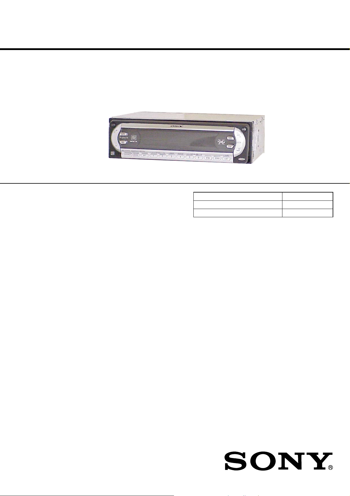
MDX-F5800
SERVICE MANUAL
Ver 1.1 2004.09
US and foreign patents licensed from Dolby
Laboratories.
SPECIFICATIONS
US Model
AEP Model
UK Model
Model Name Using Similar Mechanism NEW
MD Mechanism Type MG-165A-138
Optical Pick-up Name KMS-242E
AUDIO POWER SPECIFICATIONSAUDIO POWER SPECIFICATIONS (US model)
POWER OUTPUT AND TOTAL HARMONIC DISTORTION 23.2 watts per channel minimum
continuous average power into 4 ohms, 4 channels driven from 20 Hz to 20 kHz with no more than 5%
total harmonic distortion.
MD Player section
Signal-to-noise ratio 90 dB
Frequency response 10 − 20,000 Hz
Wow and flutter Below measurable limit
Tuner section
FM
Tuning range 87.5 − 107.9 MHz
Antenna terminal External antenna connector
Intermediate frequency 10.7 MHz/450 kHz
Usable sensitivity 9 dBf
Selectivity 75 dB at 400 kHz
Signal-to-noise ratio 67 dB (stereo),
Harmonic distortion at 1 kHz
Separation 35 dB at 1 kHz
Frequency response 30 − 15,000 Hz
AM (US model)
Tuning range 530 − 1,710 kHz
Antenna terminal External antenna connector
Intermediate frequency 10.7 MHz/450 kHz
Sensitivity 30 µV
MW/LW (AEP, UK models)
Tuning range MW: 531 − 1,602 kHz
Aerial terminal External aerial connector
Intermediate frequency 10.7 MHz/450 kHz
Sensitivity MW: 30 µV
69 dB (mono)
0.5 % (stereo),
0.3 % (mono)
LW: 153 − 279 kHz
LW: 40 µV
Power amplifier section
Outputs Speaker outputs
Speaker impedance 4 − 8 ohms
Maximum power output 52 W × 4 (at 4 ohms)
General
Outputs Audio output terminals
Inputs Telephone ATT control
Tone controls Low:
(sure seal connectors)
(front, rear/sub switchable)
Power antenna relay control
terminal
Power amplifier control
terminal
terminal
Remote controller input
terminal
BUS control input terminal
BUS audio input terminal
Antenna input terminal
±10 dB at 60 Hz (XPLOD)
Mid:
±10 dB at 1 kHz (XPLOD)
High:
±10 dB at 10 kHz (XPLOD)
Power requirements 12 V DC car battery
Dimensions Approx. 178 × 50 × 181 mm
Mounting dimensions Approx. 182 × 53 × 161 mm
Mass Approx. 1.2 kg
Supplied accessories Parts for installation and
Note
This unit cannot be connected to a digital preamplifier
or an equalizer which is Sony BUS system compatible.
Design and specifications are subject to change
without notice.
(negative ground)
1
(7
/8× 2 × 7 1/4 in)
(w/h/d)
1
/4× 2 1/8× 6 3/8 in)
(7
(w/h/d)
(2 lb 10 oz)
connections (1 set)
Front panel case (1)
FM/AM (MW/LW) MINIDISC PLAYER
9-877-611-02 Sony Corporation
2004I05-1 e Vehicle Company
© 2004.09 Published by Sony Engineering Corporation
MDX-F5800
TABLE OF CONTENTS
1. SERVICING NOTES............................................... 3
2. GENERAL
Location of Controls ....................................................... 4
3. DISASSEMBLY
3-1. Disassembly Flow ........................................................... 11
3-2. Sub Panel Assy................................................................ 12
3-3. Mechanism Deck (MG-165A-138) ................................ 12
3-4. MAIN Board ................................................................... 13
3-5. SERVO Board ................................................................. 13
3-6. MD Cover Assy............................................................... 14
3-7. Float Block ...................................................................... 14
3-8. Lever (LE23) Assy .......................................................... 15
3-9. Holder Assy ..................................................................... 15
3-10. Chucking Arm Assy ........................................................ 16
3-11. Optical Pick-up (KMS-242E) ......................................... 16
3-12. SL Motor Assy (Sled) (M902),
SP Motor Assy (Spindle) (M901)................................... 17
4. ELECTRICAL ADJUSTMENTS
Test Mode........................................................................ 17
MD Section ..................................................................... 17
Tuner Section .................................................................. 17
5. DIAGRAMS
5-1. Block Diagram – SERVO Section – ............................... 18
5-2. Block Diagram – MAIN Section – ................................. 19
5-3. Block Diagram – PANEL/BUS CONTROL/
POWER SUPPLY Section – ........................................... 20
5-4. Note for Printed Wiring Boards and
Schematic Diagrams ....................................................... 21
5-5. Schematic Diagram – SERVO Section (1/2) –............... 22
5-6. Schematic Diagram – SERVO Section (2/2) –............... 23
5-7. Printed Wiring Boards – SERVO Section – ................... 24
5-8. Printed Wiring Boards – MAIN Section – ..................... 25
5-9. Schematic Diagram – MAIN Section (1/3) –................. 26
5-10. Schematic Diagram – MAIN Section (2/3) –................. 27
5-11. Schematic Diagram – MAIN Section (3/3) –................. 28
5-12. Printed Wiring Board – SUB Board – ............................ 29
5-13. Schematic Diagram – SUB Board – ............................... 29
5-14. Printed Wiring Board – KEY Board –............................ 30
5-15. Schematic Diagram – KEY Board – .............................. 31
6. EXPLODED VIEWS
6-1. Chassis Section ............................................................... 45
6-2. Front Panel Section ......................................................... 46
6-3. Mechanism Deck Section-1 (MG-165A-138) ................ 47
6-4. Mechanism Deck Section-2 (MG-165A-138) ................ 48
6-5. Mechanism Deck Section-3 (MG-165A-138) ................ 49
7. ELECTRICAL PARTS LIST ............................... 50
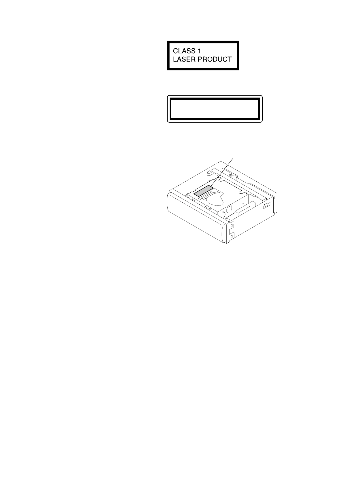
This product is classified as a
CLASS 1 LASER PRODUCT.
This label is located on the bottom of the
chassis.
CAUTION INVISIBLE
VIEW DIRECTLY
This label is located on the drive unit’s internal
chassis. (Refer to below figure)
LASER RADIATION WHEN OPEN
DO NOT STARE INTO BEAM OR
WITH OPTICAL INSTRUMENTS
– Upper view –
Caution label
During service do not take the Optical Pick-up Block apart and do
not adjust the APC circuit. If there is a breakdown in the APC
circuit (including laser diode), replace the entire Optical Pick-up
Block (including SERVO board).
Notes on chip component replacement
• Never reuse a disconnected chip component.
• Notice that the minus side of a tantalum capacitor may be dam-
aged by heat.
Flexible Circuit Board Repairing
• Keep the temperature of the soldering iron around 270 °C during repairing.
• Do not touch the soldering iron on the same conductor of the
circuit board (within 3 times).
• Be careful not to apply force on the conductor when soldering
or unsoldering.
SAFETY-RELATED COMPONENT WARNING!!
COMPONENTS IDENTIFIED BY MARK 0 OR DOTTED
LINE WITH MARK 0 ON THE SCHEMATIC DIAGRAMS
AND IN THE PARTS LIST ARE CRITICAL TO SAFE
OPERATION. REPLACE THESE COMPONENTS WITH
SONY PARTS WHOSE PART NUMBERS APPEAR AS
SHOWN IN THIS MANU AL OR IN SUPPLEMENTS PUBLISHED BY SONY.
2
p
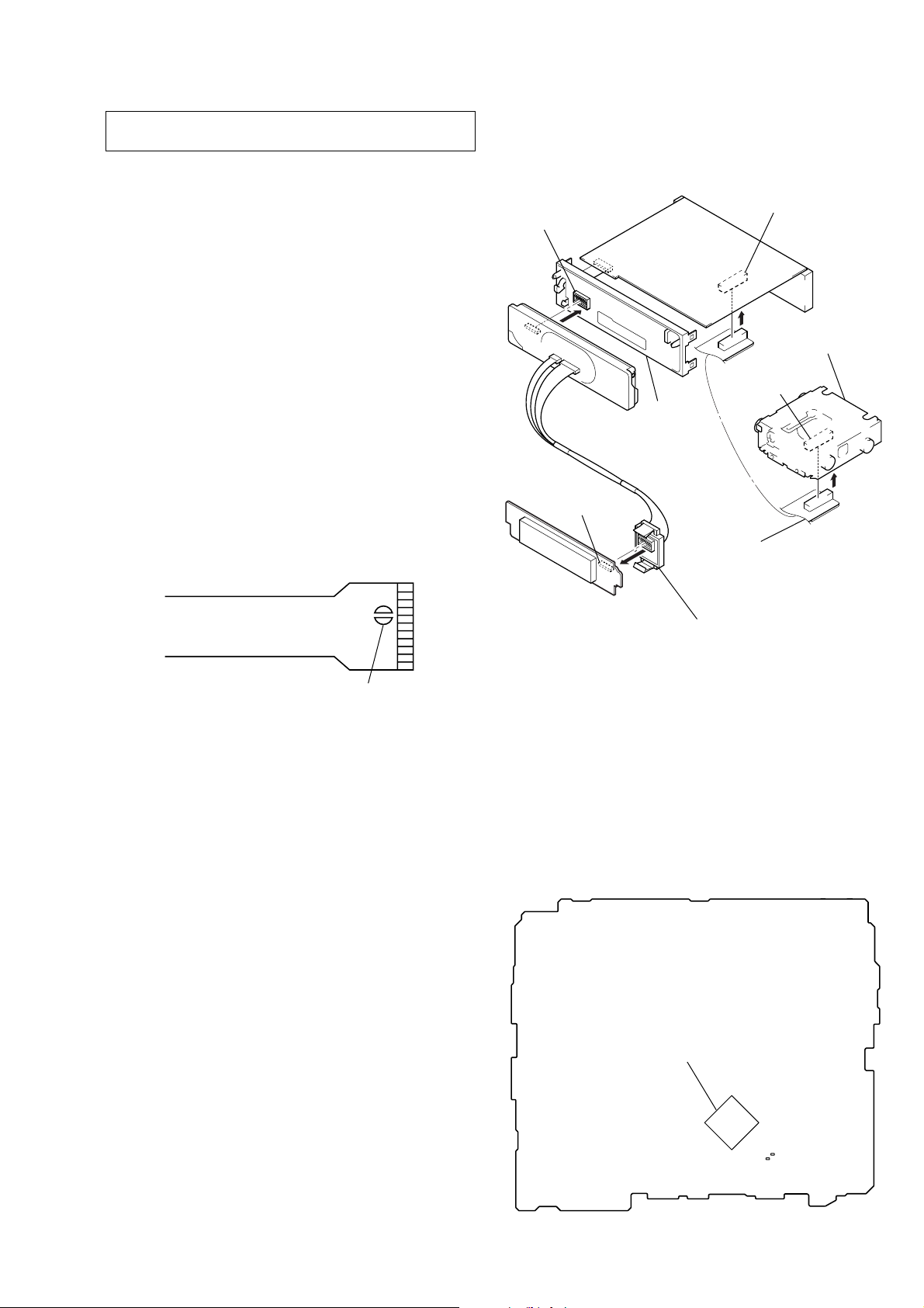
SECTION 1
– MAIN Board (Conductor Side) –
IC600
C606
C607
MN101E01KDJ : TYPE1
MN101E01JRD1 : TYPE2
SERVICING NOTES
MDX-F5800
Ver 1.1
NOTES ON HANDLING THE OPTICAL PICK-UP
BLOCK OR BASE UNIT
The laser diode in the optical pick-up block may suffer electrostatic break-down because of the potential difference generated
by the charged electrostatic load, etc. on clothing and the human
body.
During repair, pay attention to electrostatic break-down and also
use the procedure in the printed matter which is included in the
repair parts.
The flexible board is easily damaged and should be handled with
care.
NOTES ON LASER DIODE EMISSION CHECK
Never look into the laser diode emission from right avove when
checking it for adustment. It is feared that you will lose your sight.
NOTES ON HANDLING THE OPTICAL PICK-UP BLOCK
(KMS-242E).
The laser diode in the optical pick-up block may suffer electrostatic break-down easily. When handling it, perform soldering
bridge to the laser-tap on the flexible board. Also perform measures against electrostatic break-down sufficiently before the operation. The flexible board is easily damaged and should be handled
with care.
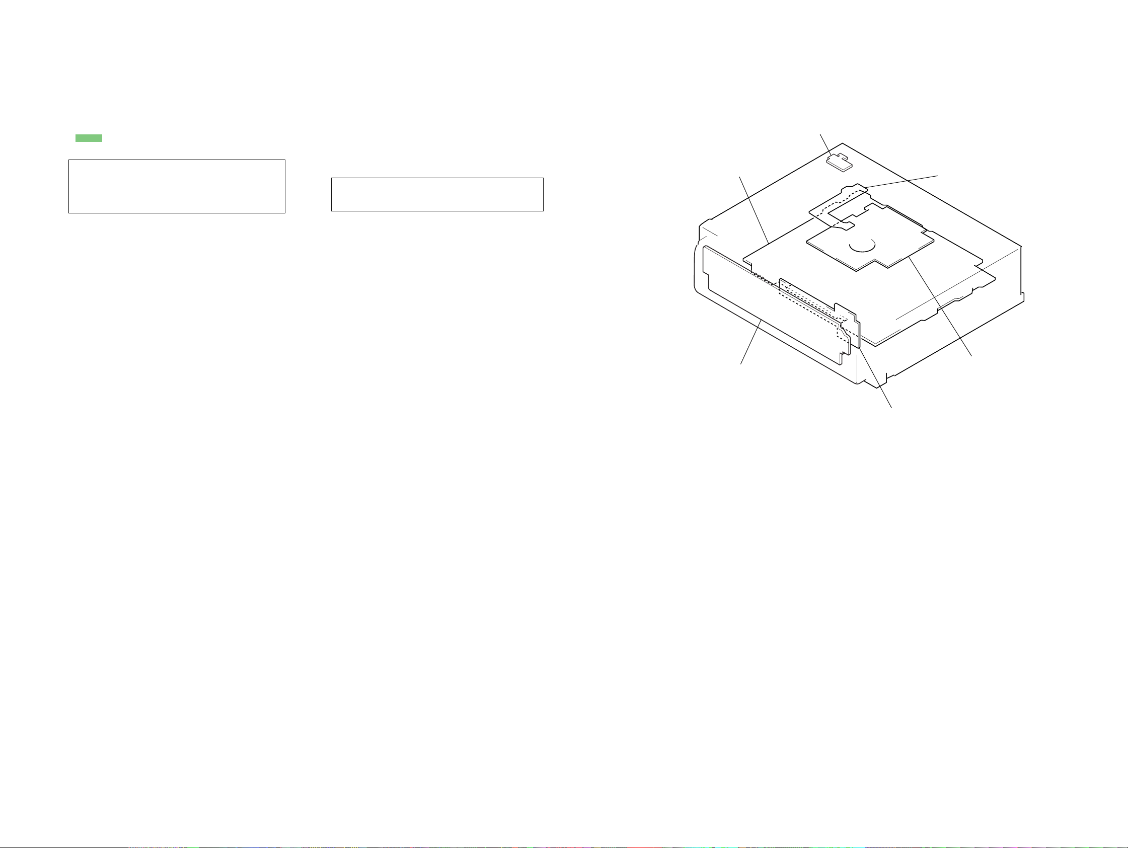
SERVICE POSITION
In checking the key board and main board, prepare two jigs (connection cable J-2502-011-1 and
connection cable for F/P to main J-2502-071-1).
sub board
(CN801)
key board
(CN901)
sub panel
assy
connect jig
(connection cable J-2502-011-1)
to the main board (CNP500) and
servo board (CN5).
main board (CNP500)
mechanism deck
servo board
(CN5)
OPTICAL PICK-UP FLEXIBLE BOARD
NOTE FOR REPLACING THE IC600
There are two types of IC600 on the MAIN board. In case IC600
is replaced, after surely checking which type of IC600 is mounted
on the set, it exchanges according to the following procedure.
In case of type1:
After surely checking the type of IC600 newly mounted on the
MAIN board, it replaces in the procedure according to each type.
Replacing procedur to type1
1. IC600 is replaced for MN101E01KDJ (PART No. 6-804-093-
01).
Replacing procedur to type2
1. IC600 is replaced for MN101E01JRD1 (PART No. 6-804-511-
02).
2. C606 is replaced for ceramic chip 15PF (PART No. 1-162917-11).
3. C607 is replaced for ceramic chip 12PF (PART No. 1-162916-11).
In case of type2:
Replacing procedure
1. IC600 is replaced for MN101E01JRD1 (PART No. 6-804-511-
02).
connect jig
(connection cable
for F/P to main J-2502-071-1)
to the key board (CN900) and
laser-ta
sub board (CN801).
3
MDX-F5800
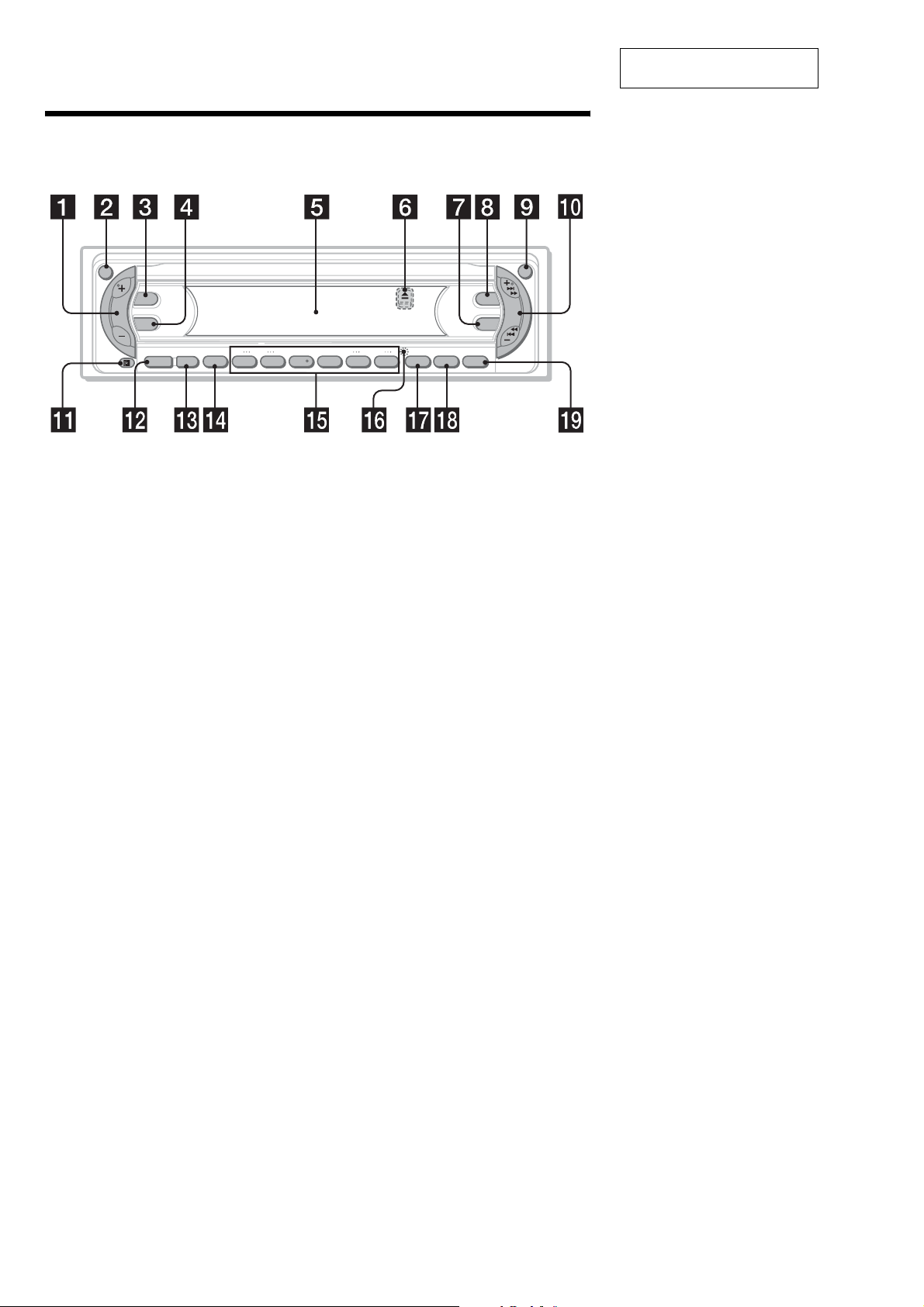
Location of controls
Refer to the pages listed for details.
SECTION 2
GENERAL
This section is extracted from
instruction manual.
AT T
DSPL
SEL
–+
DISC REP SHUF BTM LIST
SOURCE MODE
OFF
1 2 3 4 5 6
a Volume +/– button
b ATT (attenuate) button
c DSPL (display mode change) button
d SEL (select) button
To select items.
e Display window
f Z (eject) button (located on the front side
of the unit, behind the front panel)
g EQ3 button
h DSO button
i OPEN button
j SEEK +/– button
Radio:
To tune in stations automatically/find a
station manually.
MD/CD (MP3 files*
1
):
To skip tracks/fast-forward, reverse a track.
k Receptor for the card remote
commander
l SOURCE (Power on/Radio/MD/CD*
2
)
button
To select the source.
m MODE button
To change operation.
n OFF (Stop/Power off) button*
3
DSO
EQ3
–+
GP/ALBM
BTM SENS LIST
CAT
o Number buttons
Radio:
To store the desired station on each number
button.
MD/CD (MP3 files*
1
):
(1): DISC –
(2): DISC +
(3): REP
(4): SHUF
(5): GP*
(6): GP*
11
12
4
/ALBM*1 –
4
/ALBM*1 +
p RESET button (located on the front side of
the unit, behind the front panel )
q B
TM button (US model)
AF/TA button (AEP, UK models)
r S
ENS button (US model)
SENS/BTM button (AEP, UK models)
T/CAT*
5
button (US model)
s LIS
PTY (programme type)/LIST button
(AEP, UK models)
*1
Available only when an optional CD unit with the
MP3 file control function is connected, and MP3 file
is played.
*2
When an optional CD unit is connected.
*3
Warning when installing in a car without
an ACC (accessory) position on the
ignition switch
After turning off the ignition, be sure to press
and hold
(OFF)
on the unit until the display
disappears.
Otherwise, the display does not tu rn off and thi s
causes battery drain.
*4
Available only when an MD containing groups is
inserted in this unit and played.
*5
The CAT button is available only when the XM
tuner is connected.
OPEN
SEEK
4
(US model)
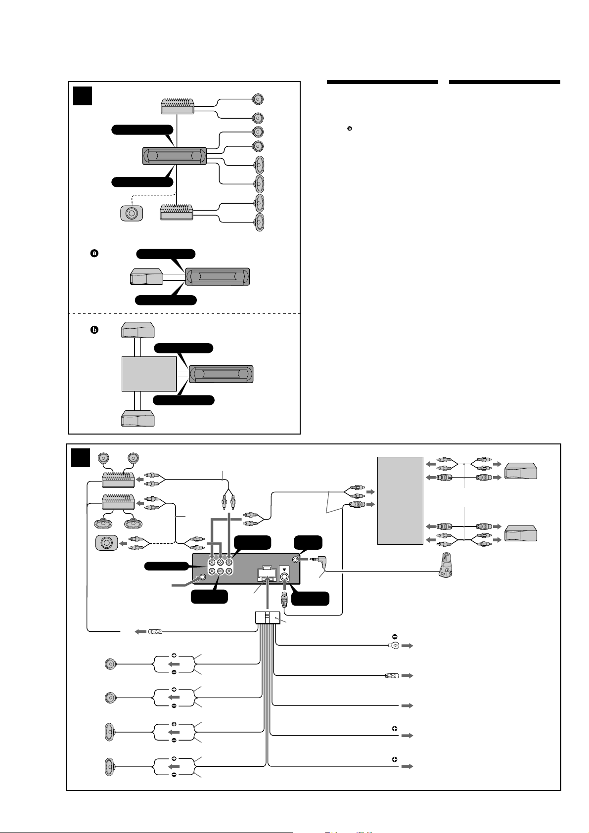
Connection example (2)
Notes (2-A)
• Be sure to connect the ground lead before connecting
the amplifier.
• If you connect an optional power amplifier and do not
use the built-in amplifier, the beep sound will be
deactivated.
Tip (2-B-
)
For connecting two or more MD/CD changers, the source
selector XA-C30 (optional) is necessary.
Connection diagram (3)
1
To a metal surface of the car
First connect the black ground lead, then connect
the yellow and red power input leads.
2
To the power antenna control lead or power
supply lead of antenna booster amplifier
Notes
• It is not necessary to connect this lead if there is no
power antenna or antenna booster, or with a
manually-operated telescopic antenna.
•When your car has a built-in FM/AM antenna in
the rear/side glass, see “Notes on the control and
power supply leads.”
3
To AMP REMOTE IN of an optional power
amplifier
This connection is only for amplifiers. Connecting
any other system may damage the unit.
4
To the interface cable of a car telephone
5
To the +12 V power terminal which is energized
in the accessory position of the ignition key
switch
Notes
• If there is no accessory position, connect to the +12
V power (battery) terminal which is energized at
all times.
Be sure to connect the black ground lead to a
metal surface of the car first.
•When your car has a built-in FM/AM antenna in
the rear/side glass, see “Notes on the control and
power supply leads.”
6
To the +12 V power terminal which is energized
at all times
Be sure to connect the black ground lead to a metal
surface of the car first.
Notes on the control and power supply leads
• The power antenna control lead (blue) supplies +12 V
DC when you turn on the tuner.
•When your car has built-in FM/AM antenna in the rear/
side glass, connect the power antenna control lead
(blue) or the accessory power input lead (red) to the
power terminal of the existing antenna booster. For
details, consult your dealer.
•A power antenna without a relay box cannot be used
with this unit.
Memory hold connection
When the yellow power input lead is connected, power
will always be supplied to the memory circuit even when
the ignition switch is turned off.
Notes on speaker connection
• Before connecting the speakers, turn the unit off.
• Use speakers with an impedance of 4 to 8 ohms, and
with adequate power handling capacities to avoid its
damage.
• Do not connect the speaker terminals to the car
chassis, or connect the terminals of the right speakers
with those of the left speaker.
• Do not connect the ground lead of this unit to the
negative (–) terminal of the speaker.
• Do not attempt to connect the speakers in parallel.
• Connect only passive speakers. Connecting active
speakers (with built-in amplifiers) to the speaker
terminals may damage the unit.
•To avoid a malfunction, do not use the built-in speaker
leads installed in your car if the unit shares a common
negative (–) lead for the right and left speakers.
• Do not connect the unit’s speaker leads to each other.
Note on connection
If speaker and amplifier are not connected correctly,
“FAILURE” appears in the display. In this case, make sure
the speaker and amplifier are connected correctly.
2
A
MDX-F5800
AUDIO OUT FRONT
AUDIO OUT REAR
B
3
Left
Right
Left
Right
BUS AUDIO IN
BUS CONTROL IN
BUS AUDIO IN
Source selector*
Sélecteur de source*
Selector de fuente*
XA-C30
BUS CONTROL IN
1
*
BUS AUDIO IN
from car antenna
AMP REM
3
1
*
AUDIO OUT
REAR
Blue/white striped
Max. supply current 0.3 A
White
White/black striped
Gray
Gray/black striped
Green
Green/black striped
Purple
Purple/black striped
2
*
AUDIO OUT
FRONT
L
R
Fuse (10 A)
* not supplied
Supplied with XA-C30
REMOTE
IN
3
*
BUS
CONTROL IN
4
Black
Blue
Light blue
Red
Yellow
Source selector
(not supplied)
ANT REM
Max. supply current 0.1 A
ATT
XA-C30
Supplied with the MD/CD changer
1
2
4
5
6
*1RCA pin cord (not supplied)
2
*
AUDIO OUT can be switched to REAR
or SUB.
For details, see the supplied operating
instructions.
3
*
Insert with the cord downwards.
5
MDX-F5800
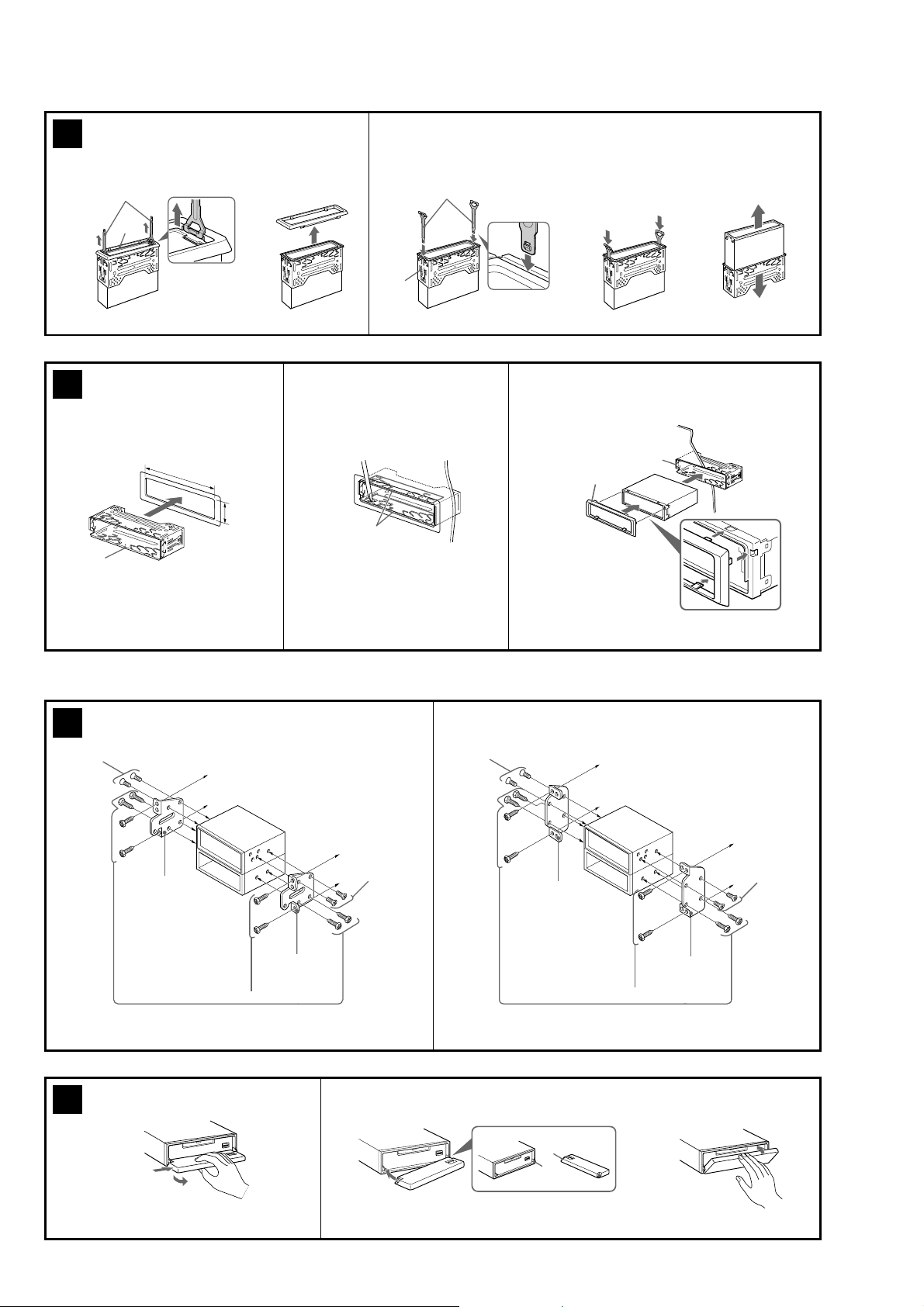
4
1
Orient the release key
correctly.
5
3
c
1 23
5
182 m
m
53 m
m
1
2
5
Face the hook inwards.
c
1
Dashboard
1
3
Claws
c
6 A
2
max. size
5 × 8 mm
7
(
/32 × 11/32 in)
Dimensions
7 A
TOYOTA
Bracket
1
2
to dashboard/center console
Existing parts supplied with your car
Bracket
B
2
max. size
5 × 8 mm
7
/32 × 11/32 in)
(
Dimensions
B
max. size
5 × 8 mm
7
(
/32 × 11/32 in)
Dimensions
NISSAN
2
Bracket
Existing parts supplied with your car
A
B
to dashboard/center console
Bracket
c
2
max. size
5 × 8 mm
7
/32 × 11/32 in)
(
Dimensions
6
MDX-F5800
Precautions
•Choose the installation location carefully so
that the unit will not interfere with normal
driving operations.
•Avoid installing the unit in areas subject to
dust, dirt, excessive vibration, or high
temperatures, such as in direct sunlight or
near heater ducts.
•Use only the supplied mounting hardware for
a safe and secure installation.
Mounting angle adjustment
Adjust the mounting angle to less than 45°.
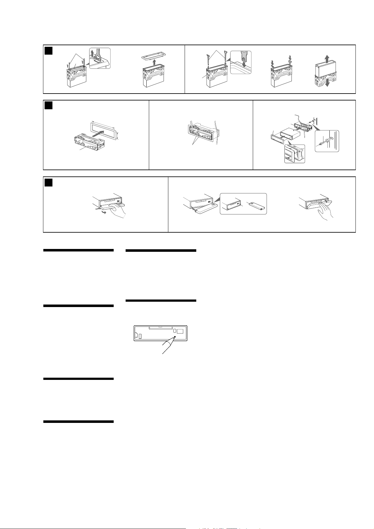
Removing the protection collar
and the bracket (4)
Before installing the unit, remove the
protection collar 3 and the bracket 1 from
the unit.
1
Remove the protection collar 3.
1 Engage the release keys 5 together with
the protection collar 3.
2 Pull out the release keys 5 to remove the
protection collar 3.
2
Remove the bracket 1.
1 Insert both release keys 5 together
between the unit and the bracket 1 until
they click.
2 Pull down the bracket 1, then pull up
the unit to separate.
Mounting example (5)
Installation in the dashboard
Notes
• Bend these claws outward for a tight fit, if
necessary (5-2).
•Make sure that the 4 catches on the protection
collar 3 are properly engaged in the slots of the
unit (5-3).
How to detach and attach the
front panel (7)
Before installing the unit, detach the front
panel.
7-A To detach
Before detaching the front panel, be sure to
press (OFF). Press (OPEN), then slide the front
panel to the right side, and pull out the left side.
7-B To attach
Place the hole A in the front panel onto the
spindle B on the unit as illustrated, then push
the left side in.
Warning when installing in a car
without ACC (accessory)
position on the ignition key
switch
After turning off the ignition, be sure to
press and hold (OFF) on the unit until the
display disappears.
Otherwise, the display does not turn off and this
causes battery drain.
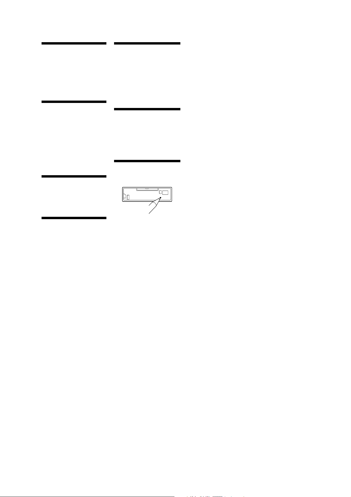
RESET button
When the installation and connections are
completed, be sure to press the RESET button
with a ball-point pen, etc., after detaching the
front panel.
Mounting the unit in a
Japanese car (6)
You may not be able to install this unit in some
makes of Japanese cars. In such a case, consult
your Sony dealer.
Note
To prevent malfunction, install only with the
supplied screws 2.
7
MDX-F5800
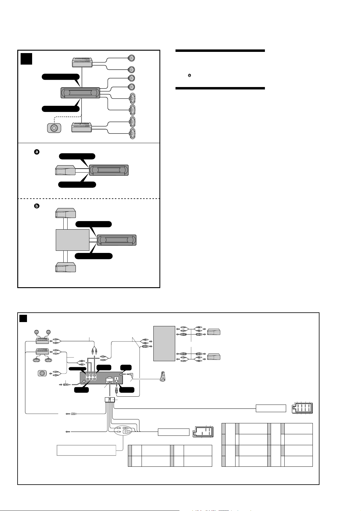
(AEP, UK models)
2
A
AUDIO OUT FRONT
AUDIO OUT REAR
B
BUS AUDIO IN
BUS CONTROL IN
BUS AUDIO IN
Connection example (2)
Notes (2-A)
• Be sure to connect the earth lead before connecting the amplifier.
• If you connect an optional power amplifier and do not use the
built-in amplifier, the beep sound will be deactivated.
Tip (2-B-
)
For connecting two or more MD/CD changers, the source selector XAC30 (optional) is necessary.
Connection diagram (3)
A
To AMP REMOTE IN of an optional power amplifier
This connection is only for amplifiers. Connecting any other
system may damage the unit.
B
To the interface cable of a car telephone
Warning
If you have a power aerial without a relay box, connecting this unit
with the supplied power connecting lead 7 may damage the aerial.
Notes on the control leads
• The power aerial control lead (blue) supplies +12 V DC when you
turn on the tuner, or when you activate the AF (Alternative
Frequency) or TA (Traffic Announcement) function.
• When your car has built-in FM/MW/LW aerial in the rear/side glass,
connect the power aerial control lead (blue) or the accessory power
input lead (red) to the power terminal of the existing aerial
booster. For details, consult your dealer.
•A power aerial without a relay box cannot be used with this unit.
Memory hold connection
When the yellow power input lead is connected, power will always
be supplied to the memory circuit even when the ignition switch is
turned off.
Notes on speaker connection
• Before connecting the speakers, turn the unit off.
• Use speakers with an impedance of 4 to 8 ohms, and with
adequate power handling capacities to avoid its damage.
• Do not connect the speaker terminals to the car chassis, or connect
the terminals of the right speakers with those of the left speaker.
• Do not connect the earth lead of this unit to the negative (–)
terminal of the speaker.
• Do not attempt to connect the speakers in parallel.
• Connect only passive speakers. Connecting active speakers (with
built-in amplifiers) to the speaker terminals may damage the unit.
•To avoid a malfunction, do not use the built-in speaker leads
installed in your car if the unit shares a common negative (–) lead
for the right and left speakers.
• Do not connect the unit’s speaker leads to each other.
Note on connection
If speaker and amplifier are not connected correctly, “FAILURE”
appears in the display. In this case, make sure the speaker and
amplifier are connected correctly.
3
Max. supply current 0.3 A
Source selector
XA-C30
2
*
BUS AUDIO IN
5
1
from car aerial
*
AUDIO OUT
AMP REM
A
AT T
B
See “Power connection diagram” on the reverse side for details.
*
BUS CONTROL IN
2
*
Fuse (10 A)
3
REAR
*
Blue/white striped
Light blue
AUDIO OUT
FRONT
L
R
* not supplied
Supplied with XA-C30
REMOTE
IN
4
*
BUS
CONTROL IN
7
4
Yellow
5
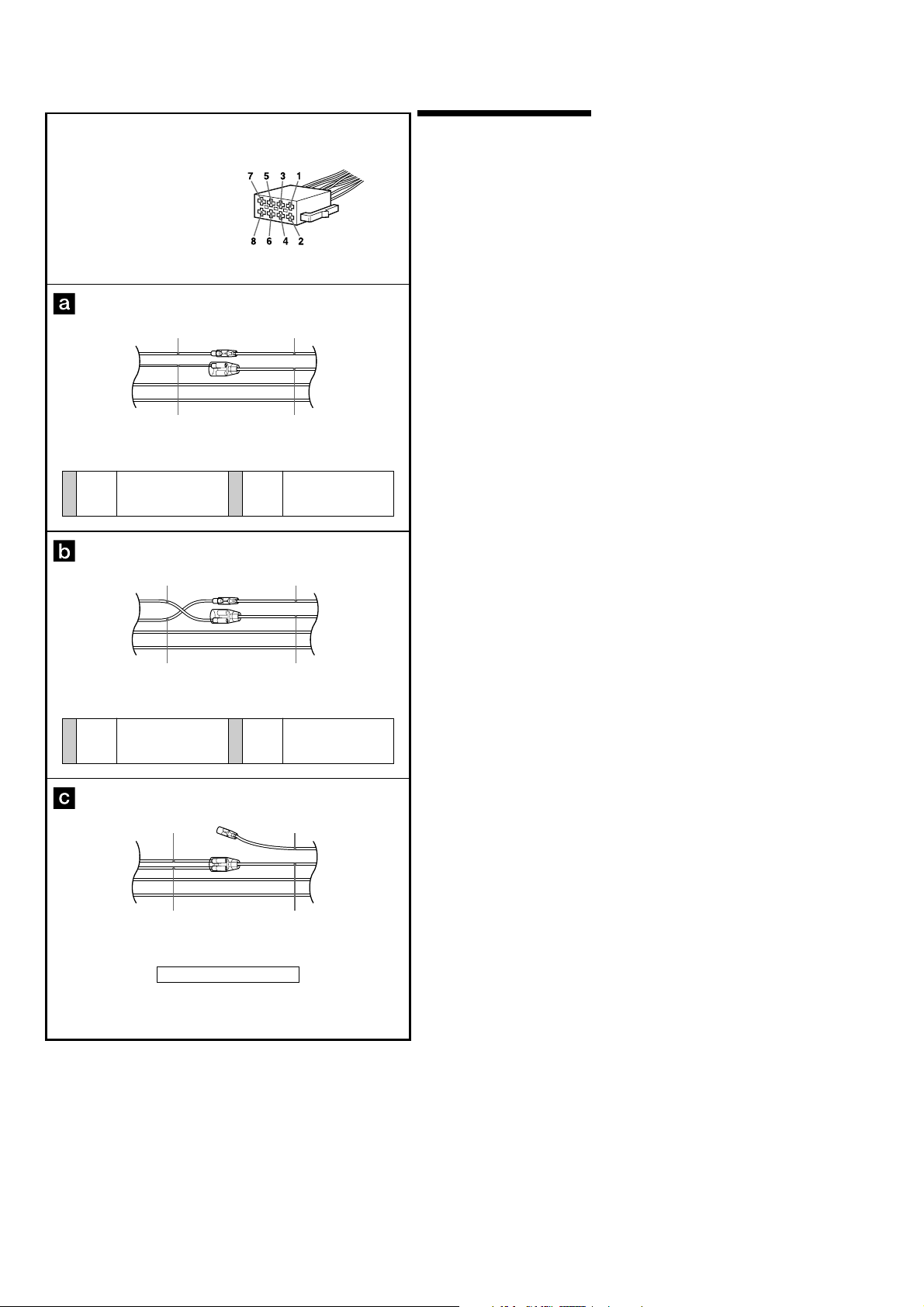
Positions 1, 2, 3 and 6 do not have pins.
Blue
Source selector
(not supplied)
continuous power supply
power aerial control
Supplied with the MD/CD changer
XA-C30
from the car’s power connector
7
Red
8
Black
48
switched power supply
earth
*1Note for the aerial connecting
If your car aerial is an ISO (International
Organisation for Standardisation) type, use the
supplied adaptor 5 to connect it.
First connect the car aerial to the supplied
adaptor, then connect it to the aerial jack of the
master unit.
2
RCA pin cord (not supplied)
*
3
AUDIO OUT can be switched REAR or SUB.
*
For details, see the Operating Instructions
manual.
4
*
Insert with the cord downwards
57
1
Purple
2
3
Grey
4
Negative polarity positions 2, 4, 6, and 8 have striped leads.
+
–
+
–
Speaker, Rear, Right
Speaker, Rear, Right
Speaker, Front, Right
Speaker, Front, Right
from the car’s speaker connector
5
White
6
7
Green
8
+
–
+
–
13 57
24 6
Speaker, Front, Left
Speaker, Front, Left
Speaker, Rear, Left
Speaker, Rear, Left
8
8
MDX-F5800
4
1
1
5 23
6
4
1
Orient the release key correctly.
182 m
m
c
53 mm
2
Claws
6
c
1
Face the hook inwards.
Dashboard
1
4
6 AB
A
1
2
B
c
c
Fire wall
2
3
Precautions
•Choose the installation location carefully so that
the unit will not interfere with normal driving
operations.
•Avoid installing the unit in areas subject to dust,
dirt, excessive vibration, or high temperature,
such as in direct sunlight or near heater ducts.
•Use only the supplied mounting hardware for a
safe and secure installation.
Mounting angle adjustment
Adjust the mounting angle to less than 45°.
Removing the protection collar
and the bracket (4)
Before installing the unit, remove the protection
collar 4 and the bracket 1 from the unit.
1
Remove the protection collar 4.
1 Engage the release keys 6 together with the
protection collar 4.
2 Pull out the release keys 6 to remove the
protection collar 4.
2
Remove the bracket 1.
1 Insert both release keys 6 together between
the unit and the bracket 1 until they click.
2 Pull down the bracket 1, then pull up the
unit to separate.
Mounting example (5)
Installation in the dashboard
Notes
• Bend these claws outward for a tight fit, if
necessary (5-2).
• Make sure that the 4 catches on the protection
collar 4 are properly engaged in the slots of the
unit (5-3).
How to detach and attach the
front panel (6)
Before installing the unit, detach the front
panel.
6-A To detach
Before detaching the front panel, be sure to press
(OFF). Press (OPEN), then slide the front panel to
the right side, and pull out the left side.
6-B To attach
Place the hole A in the front panel onto the spindle
B on the unit as illustrated, then push the left side
in.
Warning when installing in a car
without ACC (accessory)
position on the ignition key
switch
After turning off the ignition, be sure to press
and hold (OFF) on the unit until the display
disappears.
Otherwise, the display does not turn off and this
causes battery drain.
RESET button
When the installation and connections are
completed, be sure to press the RESET button with
a ballpoint pen, etc., after detaching the front panel.
9
MDX-F5800
Auxiliary power connector
Power connection diagram
Auxiliary power connector may vary depending on
the car. Check your car’s auxiliary power connector
diagram to make sure the connections match
correctly. There are three basic types (illustrated
below). You may need to switch the positions of the
red and yellow leads in the car stereo’s power
connecting lead.
After matching the connections and switched
power supply leads correctly, connect the unit to
the car’s power supply. If you have any questions
and problems connecting your unit that are not
covered in this manual, please consult the car
dealer.
4
Yellow
continuous power supply
Yellow Yellow
4
Yellow switched power supply
Red
Yellow
Red
Yellow
7
Red
switched power supply
RedRed
7
Red continuous power supply
10
Red
Yellow Yellow
the car without ACC position
Red
SECTION 3
DISASSEMBLY
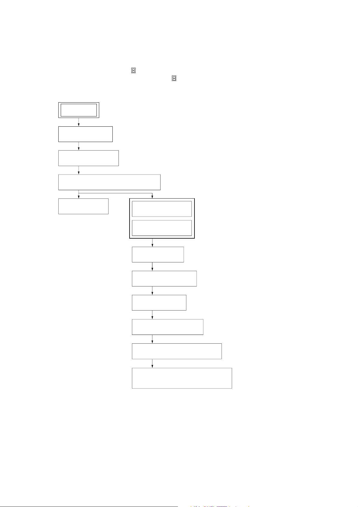
• This set can be disassembled in the order shown below.
3-1. DISASSEMBLY FLOW
Note 1: The process described in can be performed in any order.
Note 2: Without completing the process described in , the next process can not be performed.
Note 3: Illustration of disassembly is omitted.
SET
FRONT PANEL ASSY
(Note 3)
3-2. SUB PANEL ASSY
(Page 12)
3-3. MECHANISM DECK (MG-165A-138)
(Page 12)
MDX-F5800
3-4. MAIN BOARD
(Page 13)
3-5. SERVO BOARD
(Page 13)
3-6. MD COVER ASSY
(Page 14)
3-7. FLOAT BLOCK
(Page 14)
3-8. LEVER (LE23) ASSY
(Page 15)
3-9. HOLDER ASSY
(Page 15)
3-10. CHUCKING ARM ASSY
(Page 16)
3-11. OPTICAL PICK-UP (KMS-242E)
(Page 16)
3-12. SL MOTOR ASSY (SLED) (M902),
SP MOTOR ASSY (SPINDLE) (M901)
(Page 17)
11
MDX-F5800
r
)
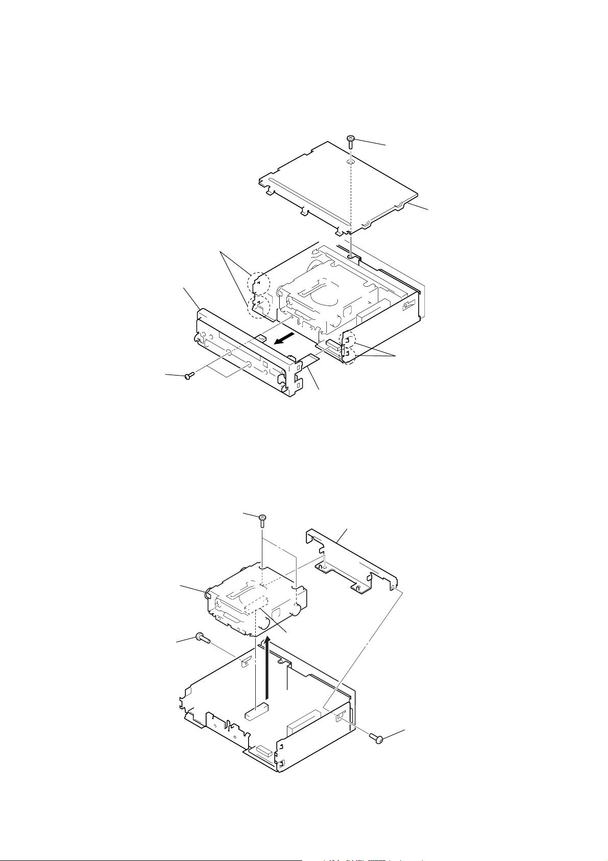
Note: Follow the disassembly procedure in the numerical order given.
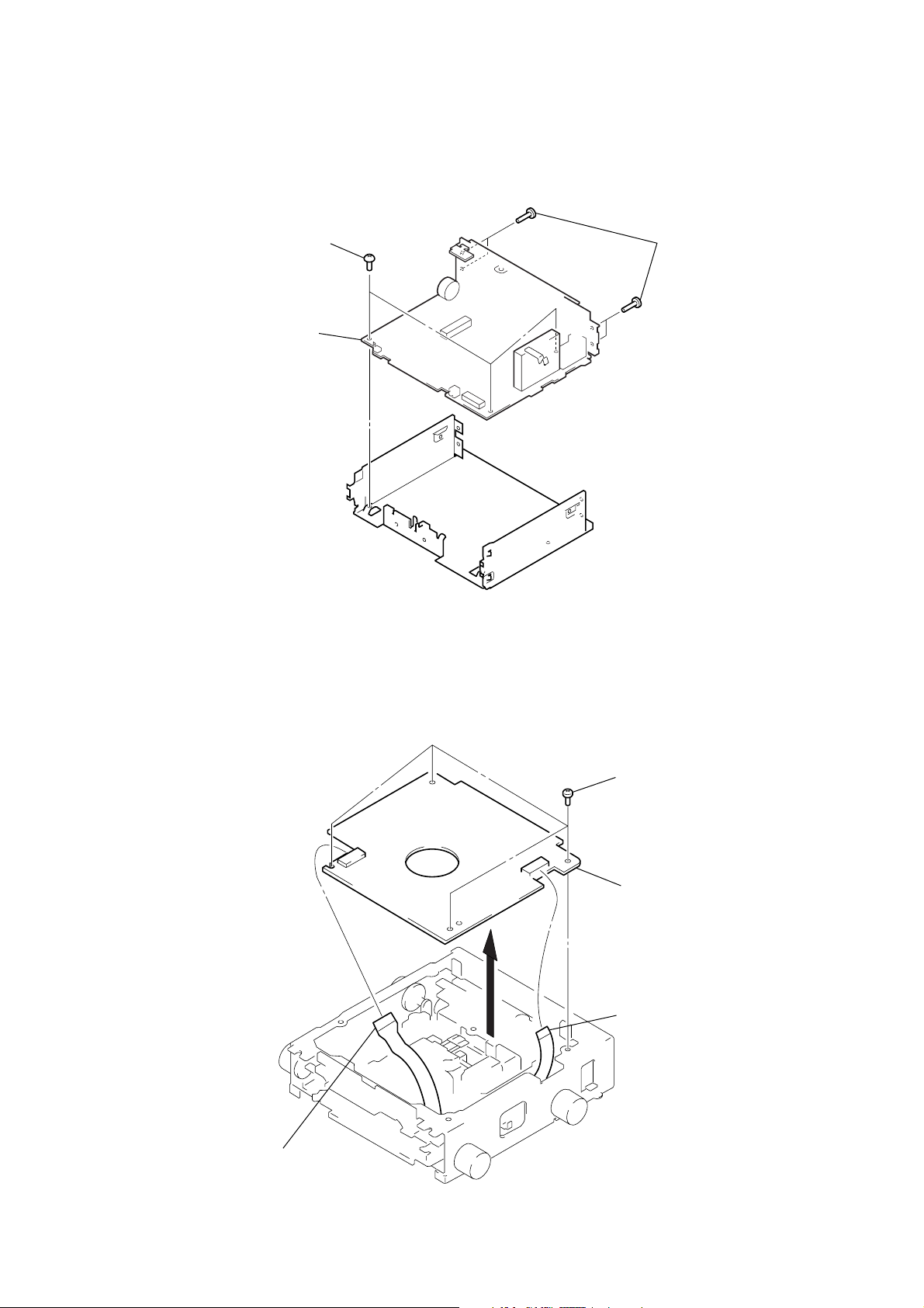
3-2. SUB PANEL ASSY
4
two claws
7
sub panel assy
1
screw
(PTT2.6 × 6)
2
cove
3
two screws
(PTT2.6 × 6)
3-3. MECHANISM DECK (MG-165A-138)
3
two screws
(PTT2.6
5
mechanism deck
(MG-165A-138)
1
screw
(PTT2.6
×
6)
5
4
two claws
6
flexible flat (14 core) cable
(CN370)
×
6)
4
bracket (MD)
2
connector
(CNP500)
12
1
screw
(PTT2.6
×
6
3-4. MAIN BOARD
e
1
3
three screws
(BTT2.6
main board
MDX-F5800
×
5)
2
four screws
(PTT2.6
×
6)
3-5. SERVO BOARD
2
four screws
×
(BVTT2
3
servo board
1
parallel (FFC) (10core) wir
(CN3)
4)
1
optical pick-up flexible board
(CN2)
13
MDX-F5800
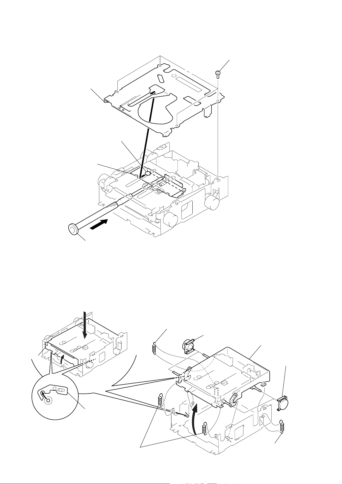
)
y
3-6. MD COVER ASSY
3
MD cover assy
shaft (MD cover guide)
cassette holder
1
four screws
(BVTT2 × 4
3-7. FLOAT BLOCK
float block
A
2
Pushing the cassette holder in the direction of the arrow A with a
screwdriver, etc., disengage the shaft (MD cover guide) from
the slot in the MD cover assy.
Note: Take care not to scratch the optiocal pick-up when pushing
the cassette holder with a screwdriver. etc.
3
Pushing an arrow A part, raise the float block
up ward at the front to release a lock.
1
tension spring (FL2)
A
5
two dampers assy
6
float block
5
two dampers ass
14
lever (lock R)
lever (lock L)
2
two tension springs (float F)
4
1
tension spring (FL2)
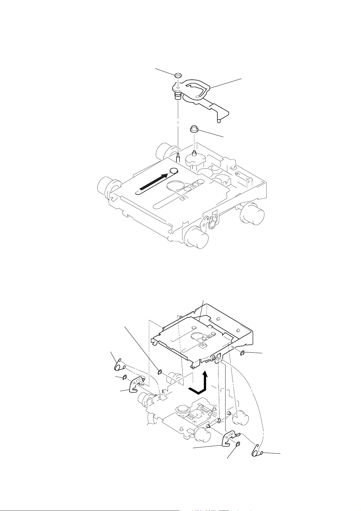
3-8. LEVER (LE23) ASSY
y
2
stopper washer
1
4
roller (GLE)
3
lever (LE23) ass
MDX-F5800
3-9. HOLDER ASSY
2
1
spring (CHKG)
2
type-E stop ring 1.5
3
lever (lock R)
type-E stop ring 1.5
4
Remove the holder assy in the
direction of the arrow.
2
type-E stop ring 1.5
3
lever (lock L)
2
type-E stop ring 1.5
1
spring (CHKG)
15
MDX-F5800
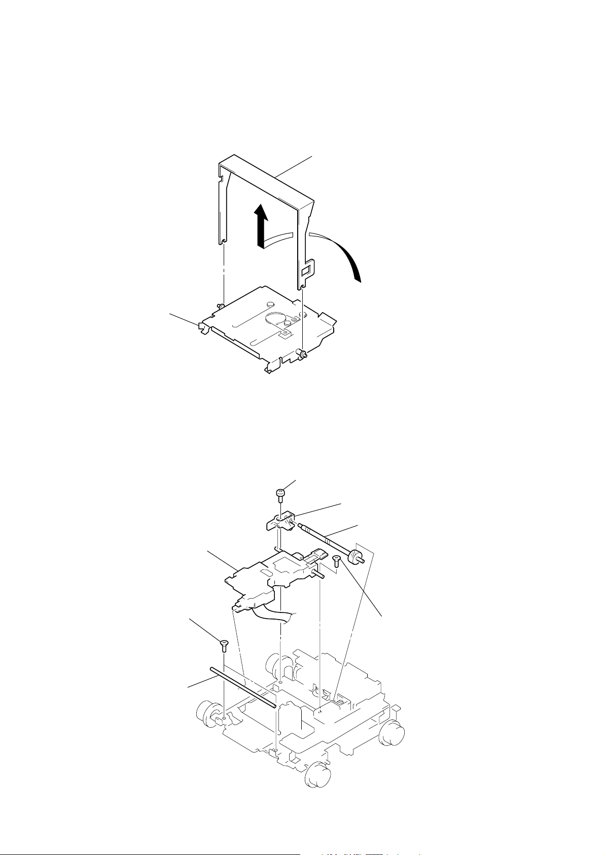
y
3-10. CHUCKING ARM ASSY
holder assy
1
Remove the chucking arm ass
in the direction of the arrow.
3-11. OPTICAL PICK-UP (KMS-242E)
7
optical pick-up
(KMS-242E)
1
two screws
(K2
×
3)
2
shaft (SL2)
4
screw
(B2
×
3)
6
bearing (SL)
5
feed screw assy
3
screw
(K2
×
3)
16
SECTION 4
ELECTRICAL ADJUSTMENTS
MDX-F5800
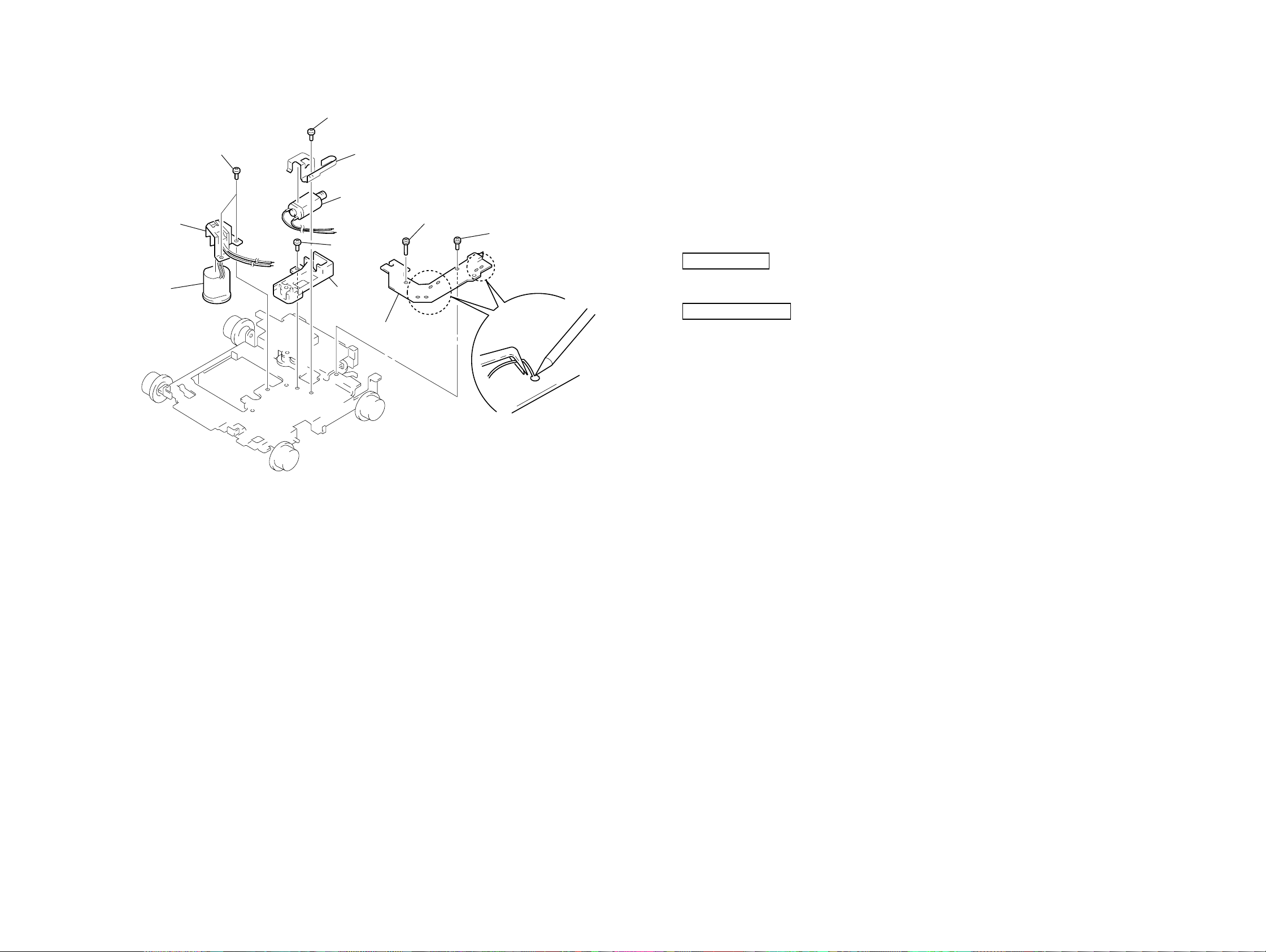
3-12. SL MOTOR ASSY (SLED) (M902), SP MOTOR ASSY (SPINDLE) (M901)
5
screw
×
1.8)
(P1.7
0
two screws
(P1.7
×
qa
retainer (SP)
qs
SP motor assy
(spindle) (M901)
1.8)
9
6
7
SL motor assy
(sled) (M902)
8
screw
×
(B2
base (SL)
bracket (SL)
3)
4
sensor board
3
screw (PS2 × 8)
2
screw (PS2 × 4)
TEST MODE
This set have the test mode function.
<Set the Test Mode>
1. Turn ON the regulated pow er supply. (The clock is displayed)
Note: Press the [OFF] button, if the clock is not displayed.
2. Push the preset [4] button.
3. Push the preset [5] button.
4. Press the preset [1] button for more than two seconds.
5. Then the display indicates all lights, the test mode is set.
<Release the Test mode>
1. Push the [OFF] button.
MD SECTION
MD section adjustments are done automatically in this set.
TUNER SECTION
Tuner section adjustments are done automatically in this set.
1
Remove solders of motors
(M901, M902, M903).
1717
MDX-F5800
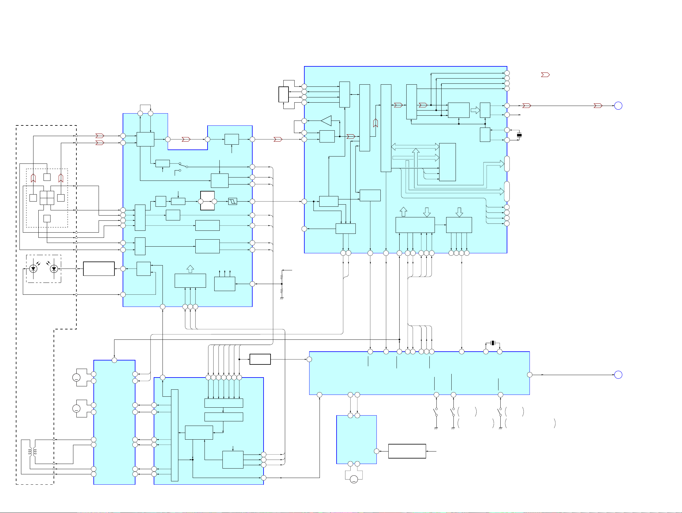
5-1. BLOCK DIAGRAM − SERVO Section −
SECTION 5
DIAGRAMS
OPTICAL PICK-UP BLOCK
(KMS-242E)
F
C B
I J
A
D
E
DETECTOR
LDPD
LASER DIODE
ILCC
MON
I
J
B
A
C
D
E
F
AUTOMATIC
POWER CONTROL
Q1
MD DSP
IC4 (1/2)
DADT
36
XBCK
38
LRCK
FILI
105
PCO
104
CLTV
107
FILTER
48 47
MORFI
MORFO
I
1
J
2
A
4
B
5
I-V
C
AMP
6
D
7
E
8
I-V
F
AMP
9
APC
11
PD
10
RF AMP
LD/PD
AMP
RFO
46 40
B.P.F.
3T
TEMP
WBL
AT
B.P.F.
AMP
ABCD
AMP
COMMAND
SERIAL/PARALLEL
CONVERTER,
DECODER
APCREF
12
SWDT
ADFM
SCLK
FOCUS
ERROR AMP
TRACKING
ERROR AMP
XLAT
181716
RF AMP,
FOCUS/TRACKING ERROR AMP
AGCI
WBL
PEAK &
BOTTOM
ADIN
3029
EQ
V-I
CONVERTER
IC1
RF AGC
& EQ
EQ
3T
WBL
RF
AUX AUX
PEAK
BOTM
ADFG
ABCD
FE
TE
SE
F0CNT
38
33
PEAK
37
BOTM
36
32
ABCD
35
FE
34
TE
26
SE
28
20
SERVO
3.3V
106
98
99
102
67
70
FILO
ASYO
ASYI
RFI
ADFG
F0CNT
COMPA-
RATOR
DECODER
ADIP
PLL
SPINDLE
SERVO
SPFD
SPRD
114 113
SPFD
SPRD
EFM/ACIRC DECODER
SUBCODE
PROCESSOR
SQSY35XINT
16
ATRAC
SHOCK RESISTANT
MEMORY CONTROLLER
INTERFACE
XRST
SENS13SRDT
15 14 9 10 11
SENS
ENCODER/DECODER
XWE
XRAS
XCAS
CPU
SWDT
SCLK
XLAT
SRDT
SWDT
SCLK
XLAT
4Mbit
D-RAM
D/A
CONVERTER
MONITOR
CONTROL
MNT0
MNT1
MNT2
5 6 7 8
LPF
OSC
MNT3
37
FS256
39
AOUTL L-CH
25
AOUTR
28
OSCI
20
OSCO
21
D0 – D3A00 – A11
60 – 63
41 – 51, 55
XOE
53
XWE
57
XRAS
56
XCAS
54
• R-ch is omitted due to same as L-ch.
• SIGNAL PATH
: MD PLAY
R-CH
X1
22.57MHz
A
(Page 19)
2-AXIS
DEVICE
(TRACKING)
FCS+
(FOCUS)
FCS–
TRK+
TRK–
FOCUS/TRACKING COIL DRIVE,
SPINDLE/SLED MOTOR DRIVE
M901
(SPINDLE)
M902
(SLED)
IC2
MM
M
DTRF
CKRF
XLRF
SRDT
SENS
SRDT
SWDT
SWDT
(LIMIT)
SCLK
SCLK
MD-LAT
LIMIT_IN
LO_6V
MNT2
LOAD_END
CHUCKING
DETECT
ON : When completion
of a disc loading
SENS
FE
TE
SE
AUX
PEAK
ABCD
16
PSB
OUT4F
6
OUT4R
8
OUT2F
27
OUT2R
25
OUT1F
21
23
OUT1R
OUT3F
12
10
OUT3R
IN4R
IN4F
IN2F
IN2R
IN1F
IN1R
IN3F
IN3R
SPFD
3
SPRD
4
SFDR
29
30
19
18
14
15
112
SRDR
111
FFDR
64
FRDR
65
TFDR
77
TRDR
76
MD DSP
IC4 (2/2)
74 83 92 91 80 81 84 82
FE
APCREF
DIGITAL SERVO
SIGNAL
PROCESS
PWM GENERATOR
BOTM
TE
SE
PEAK
BOTM
ANALOG MUX
A/D CONVERTER
FROM CPU
INTERFACE
AUTO
SEQUENCER
AUX
ABCD
PEAK HOLD
XLRF
CKRF
DTRF
FOK/FCS
Q2
XLRF
71
CKRF
72
DTRF
73
120
REF_
41
LEVEL
FOK
100 85
84
5 4
LOADING
MOTOR DRIVE
1 7
M903
(LOADING)
52 46 1695 18
SQ_SY
CC-XINT
MD MECHANISM CONTROLLER
EJECT
LOAD
FIN
RIN
IC6
6
VREF
OUT1
OUT2
M
MD-RST
IC7 (1/2)
REFERENCE VOLTAGE
REGULATOR
Q3
XLAT
X2
18.43MHz
8194
X1
8019 9817
X0
ATT
DISC-IN
538887
LOADING
DETECT
ON : When a disc loading start
and a disc eject completion
7
MECH_ATT
B
(Page 19)
1818
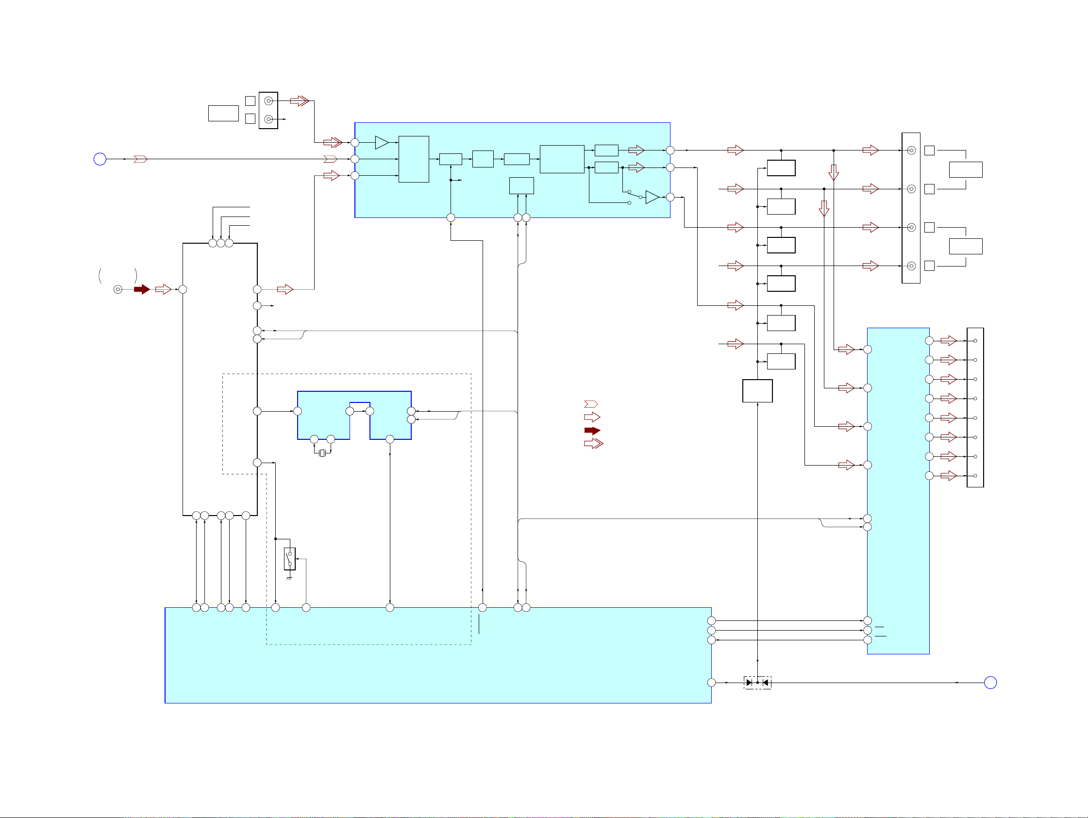
5-2. BLOCK DIAGRAM − MAIN Section −
MDX-F5800
(Page 18)
L-CH
A
J10
FM/AM
ANTENNA IN
ANT
PJ210 (1/2)
BUS
AUDIO IN
15
10 11
E2PVDD
VCC8.3V
FM/AM
TUNER PACK
TU10
VDD5V
SDA
SCL
L
R
L
R
BU5.0V
AU 8.3V
TU5V
41
14
11313
119RDS_OUT
115QUALITY
R-CH
R-CH
I2C_SDA
I2C_SCL
RDS DECODER
16 MPX 19 CIN
OSCI
OSCO
5 4
X90
4.332MHz
BUS-LCH
5
MD-LCH
11
TU-LCH
7
IC90
1118SCOUT 119SDA
DAVN
8
INPUT
SELECTOR
1110SCL
INPUT SELECT,
ELECTRICAL VOLUME
MUTE
R-CH
INPUT
GAIN
MUTE VOLUME
(AEP, UK)
I2C_SDA
I2C_SCL
IC120
IIC BUS
LOGIC
SDA
31
I2C_SDA
SCL
3029
I2C_SCL
TONE CONTROL/
EFFECT
CIRCUIT
OUT-FL
OUT-RL
23
22
17
FADER
FADER
SUBOUT-RL
• R-ch is omitted due to same as L-ch.
• SIGNAL PATH
: MD PLAY
: FM
: AM
: BUS AUDIO IN
R-CH
R-CH
R-CH
MUTING
CONTROL
Q350, 351
MUTING
Q210
MUTING
Q240
MUTING
Q220
MUTING
Q230
MUTING
Q260
MUTING
Q250
12
14
11
15
POWER AMP
IC300 (1/2)
IN-FL
IN-FR
IN-RL
IN-RR
PJ210 (2/2)
OUT-FL+
OUT-FL–
OUT-FR+
OUT-FR–
OUT-RL+
OUT-RL–
OUT-RR+
OUT-RR–
L
AUDIO OUT
FRONT
R
L
AUDIO OUT
REAR
R
CN300 (1/2)
5
3
21
23
9
7
17
19
1
9
4
12
2
10
3
11
FRONT L+
FRONT L–
FRONT R+
FRONT R–
REAR L+
REAR L–
REAR R+
REAR R–
E2PSDA
17 16
68
E2P_SIO
E2PSCL
67
E2P_CKO
TUN_MUTE
MUTE_CON
7 8
64
28
TUATT
TUATTIN
6
93
VSM S-METER
92
QUALITY
Q71
NOISE DET
DISCHARGE
SWITCH
66
NS_MASK
82
DAVN
SYSTEM CONTROLLER
IC600 (1/2)
I2C_SDA
57 79 81
VOLATT
I2C_SIO
I2C_SCL
I2C_CKO
BEEP
AMPSTB
DIAG
ATT
I2C_SDA
I2C_SCL
85
70
56
24
D350
2
SDA
4
SCL
16
BEEP
22
STB
25
DIAG
MECH_ATT
B
(Page 18)
1919
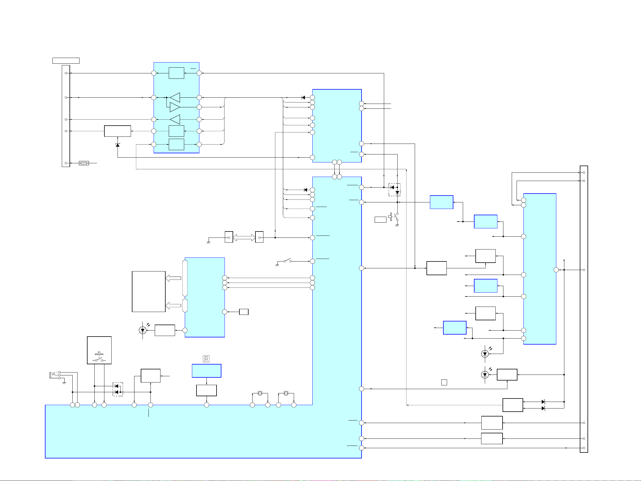
MDX-F5800
5-3. BLOCK DIAGRAM − PANEL/BUS CONTROL/POWER SUPPLY Section −
CNJ400
BUS CONTROL IN
RESET
DATA
CLK
BUS ON
BATT
SONY BUS INTERFACE
IC400
2
5
4
6
TH400
7
BUS ON SWITCH
BAT B+
Q401
D404
RST
DATA I/O
CLK
BUS
ON
BATT
RESET
SWITCH
BUS ON
SWITCH
BATTERY
SWITCH
2 13
6 9
4 11
1 12
3 10
RST
DATA IN
DATA OUT
8
CLK-IN
BUS ON
B/U_C BU_IN
UNISO
UNISI
UNICKO
BUS-ON
CN901
FRONT PANEL
SIDE
1
CN370
MAIN UNIT SIDE
5
UNISO
UNISI
UNICKO
BUS-ON
BU_IN
UNISO
UNISI
UNICKO
BUS-ON
BUS-ON
MD MECHANISM CONTROLLER
D405
(1/2)
57
UNISO
56
UNISI
UNICLK
58
50
BUS_ON
51 BU_IN
14
EJECT_OK
2
LINKOFF
D405
(2/2)
33
UNISO
UNISI
34
UNICKO
35
BUSON
40
31 BU_IN
DOORSW
55
IC7 (2/2)
MDMON
1 15
30 39
MDMON
RSTX
OPEN_REQ
OPENREQ
S601
RESET
D500
LO_6V
SERVO3.3V
RESET SIGNAL
GENERATOR
IC601
BU3.3V
+3.3V
REGULATOR
IC700
BU5.0V
REGULATOR
IC300 (2/2)
27 ANT-REM
29 AMP-REM
37 REG2
CN300 (2/2)
5
6
AMP-R
ANT-R
69MDMON_CHECK
70MDON_CHECK
93MD_ON
75
42SYSRST
19RESET
J370
(REMOTE IN)
S901 – 907,
S910 – 923
96 20 95
RCIN0
RCIN1
LSW801,
KEYIN0
94
KEYIN1
D600
78
DI
77
CL
76
LIQUID CRYSTAL
DISPLAY
LCD901
LED DRIVE
Q961
LED961, 962
(LCD BACK LIGHT)
KEY ACTIVE
SWITCH
Q600
27 25 12 13
ADON
KEYACK
BU3.3V
LCD DRIVER
65 – 68 7 – 14, 16 – 31, 33 – 64
COM1 – COM4 SEG1 – SEG56
1 LED
REMOTE CONTROL
RECEIVER
SIRCS AMP
Q371, 372
SYSTEM CONTROLLER
IC901
IC971
83
IC600 (2/2)
SIRCS
OSC
CE
74
OSC
C985, R989
X601
27.648MHz
OSCOUT
(NOSE DETECT)
16 15
OSCIN
S600
X602
32.768kHz
XOUT
XIN
59
76
78
77
NOSESW
LCDSO
LCDCKO
LCDCE
DOORIND
+5V
LED801,
LED802
REGULATOR
Q504
+2.5V
REGULATOR
IC3
+5V
REGULATOR
Q60
AU8.3V
ACCESSORY
CHECK
Q361
LEVEL SHIFT
Q360
LED DRIVE
Q370
VOLTAGE
CHECK
Q402
33 REG4
31 REG3
30 REG1
34 REG5
D406
D407
35VP
BAT B+
19
+B
7
ACC
13
TEL-ATT
15
TEST
DRIVER5V
29MDON
69
21ACCIN
23TELATT
22TESTIN
REGULATOR
CONTROL
Q505
SERVO3.3V
+3.3V
LCD3.3V
(DISC SLOL ILLUMINATION)
REGULATOR
LED801
LED802
Z
IC981
LO_6V
L2.5V
TU5V
ILL 10V
LED901 – 907,
LED910 – 923
2020
MDX-F5800
5-4. NOTE FOR PRINTED WIRING BOARDS AND SCHEMATIC DIAGRAMS
Note on Printed Wiring Board:
• X : parts extracted from the component side.
• Y : parts extracted from the conductor side.
f
•
• : Pattern from the side which enables seeing.
(The other layers' patterns are not indicated.)
Caution:
Pattern face side: Parts on the pattern face side seen from
(Side B) the pattern face are indicated.
Parts face side: Parts on the parts face side seen from
(Side A) the parts face are indicated.
: internal component.
Note on Schematic Diagram:
• All capacitors are in µF unless otherwise noted. pF: µµF
50 WV or less are not indicated except for electrolytics
and tantalums.
• All resistors are in Ω and 1/
specified.
f
•
• C : panel designation.
Note: The components identified by mark 0 or dotted line
• A : B+ Line.
• Power voltage is dc 14.4V and fed with regulated dc power
• Voltages and waveforms are dc with respect to ground
• Voltages are taken with a VOM (Input impedance 10 MΩ).
• Waveforms are taken with a oscilloscope.
• Circled numbers refer to waveforms.
• Signal path.
: internal component.
with mark 0 are critical for safety.
Replace only with part number specified.
supply from ACC and BATT cords.
under no-signal (detuned) conditions.
− SERVO Section −
no mark : MD PLAY
− MAIN/KEY Section −
no mark : FM
〈〈 〉〉 : AM (MW/LW)
(): MD PLAY
Voltage variations may be noted due to normal production tolerances.
Voltage variations may be noted due to normal production tolerances.
E : MD PLAY
F : FM
f : AM (MW/LW)
L : BUS AUDIO IN
4
W or less unless otherwise
• Circuit Boards Location
MAIN board
KEY board
MINIATURE JACK board
SENSOR board
SERVO board
SUB board
2121
 Loading...