

Page 1
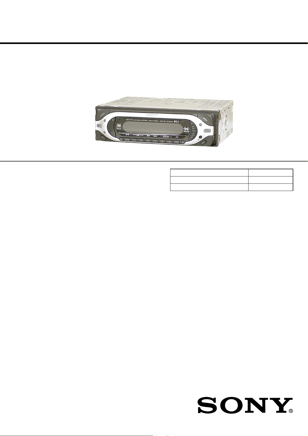
MDX-CA790X
SERVICE MANUAL
Ver 1.0 2003.03
U.S. and foreign patents licensed from Dolby Laboratories.
SPECIFICATIONS
AEP Model
UK Model
Model Name Using Similar Mechanism NEW
Base Mechanism Type MG-165A-138
Optical Pick-up Name KMS-242E
MD Player section
Signal-to-noise ratio 90 dB
Frequency response 10 – 20,000 Hz
Wow and flutter Below measurable limit
Tuner section
FM
Tuning range 87.5 – 108.0 MHz
Aerial terminal External aerial connector
Intermediate frequency 10.7 MHz/450 kHz
Usable sensitivity 9 dBf
Selectivity 75 dB at 400 kHz
Signal-to-noise ratio 67 dB (stereo),
Harmonic distortion at 1 kHz
Separation 35 dB at 1 kHz
Frequency response 30 – 15,000 Hz
MW/LW
Tuning range MW: 531 – 1,602 kHz
Aerial terminal External aerial connector
Intermediate frequency 10.7 MHz/450 kHz
Sensitivity MW: 30 µV
Power amplifier section
Outputs Speaker outputs
Speaker impedance 4 – 8 ohms
Maximum power output 50 W × 4 (at 4 ohms)
69 dB (mono)
0.5 % (stereo),
0.3 % (mono)
LW: 153 – 279 kHz
LW: 40 µV
(sure seal connectors)
General
Outputs Audio outputs (front)
Inputs Telephone ATT control
Tone controls Low ±10 dB at 60 Hz
Power requirements 12 V DC car battery
Dimensions Approx. 17 8 × 50 × 180 mm
Mounting dimensions Approx. 182 × 53 × 161 mm
Mass Approx. 1.2 kg
Supplied accessories Parts for installation and
Note
This unit cannot be connected to a digital preamplifier
or an equalizer which is Sony BUS system compatible.
Design and specifications are subject to change
without notice.
Audio outputs (rear)
Power aerial relay control
terminal
Power amplifier control
terminal
terminal
Remote controller input
terminal
BUS control input ter minal
BUS audio input termina l
(XPLOD)
Mid ±10 dB at 1 kHz
(XPLOD)
High ±10 dB at 10 kHz
(XPLOD)
(negativ e eart h )
(w/h/d)
(w/h/d)
connections
Front panel case (1)
9-877-086-01 Sony Corporation
2003C0500-1 e Vehicle Company
C 2003.03 Published by Sony Engineering Corporation
FM/MW/LW MINIDISC PLAYER
Page 2
MDX-CA790X
TABLE OF CONTENTS
1. SERVICING NOTES............................................... 3
2. GENERAL
Location of Controls ....................................................... 4
3. DISASSEMBLY
3-1. Disassembly Flow ........................................................... 8
3-2. Sub Panel Assy................................................................ 9
3-3. Mechanism Deck (MG-165A-138) ................................ 9
3-4. MAIN Board ................................................................... 10
3-5. SERVO Board ................................................................. 10
3-6. MD Cover Assy............................................................... 11
3-7. Float Block ...................................................................... 11
3-8. Lever (LE23) Assy .......................................................... 12
3-9. Holder Assy ..................................................................... 12
3-10. Chucking Arm Assy ........................................................ 13
3-11. Optical Pick-up (KMS-242E) ......................................... 13
3-12. SL Motor Assy (Sled) (M902),
SP Motor Assy (Spindle) (M901)................................... 14
4. ELECTRICAL ADJUSTMENTS
Test Mode........................................................................ 15
MD Section ..................................................................... 15
Tuner Section .................................................................. 15
5. DIAGRAMS................................................................. 16
5-1. Block Diagram – SERVO Section – ............................... 20
5-2. Block Diagram – MAIN Section – ................................. 21
5-3. Block Diagram – PANEL/BUS CONTROL/
POWER SUPPLY Section – ........................................... 22
5-4. Note for Printed Wiring Boards and
Schematic Diagrams ....................................................... 23
5-5. Schematic Diagram – SERVO Section (1/2) –............... 24
5-6. Schematic Diagram – SERVO Section (2/2) –............... 25
5-7. Printed Wiring Boards – SERVO Section – ................... 26
5-8. Printed Wiring Boards – MAIN Section – ..................... 27
5-9. Schematic Diagram – MAIN Section (1/3) –................. 28
5-10. Schematic Diagram – MAIN Section (2/3) –................. 29
5-11. Schematic Diagram – MAIN Section (3/3) –................. 30
5-12. Printed Wiring Board – SUB Section – .......................... 31
5-13. Schematic Diagram – SUB Section –............................. 31
5-14. Printed Wiring Board – KEY Section – ......................... 32
5-15. Schematic Diagram – KEY Section – ............................ 33
5-16. IC Pin Function Description ........................................... 34
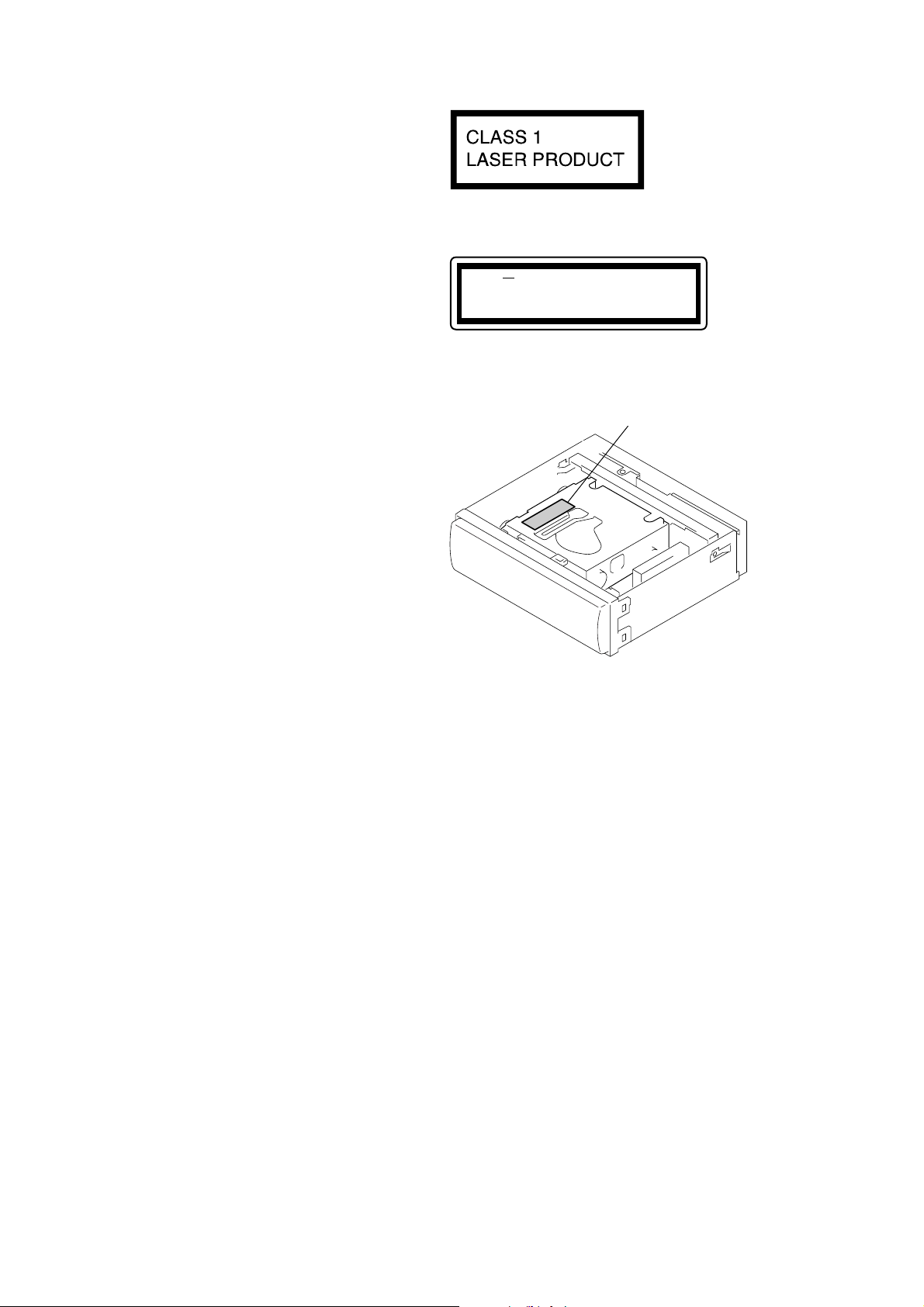
This product is classified as a
CLASS 1 LASER PRODUCT.
This label is located on the bottom of the
chassis.
CAUTION INVISIBLE
VIEW DIRECTLY
This label is located on the drive unit’s internal
chassis. (Refer to below figure)
LASER RADIATION WHEN OPEN
DO NOT STARE INTO BEAM OR
WITH OPTICAL INSTRUMENTS
– Upper view –
Caution label
During service do not take the Optical Pick-up Block apart and do
not adjust the APC circuit. If there is a breakdown in the APC
circuit (including laser diode), replace the entire Optical Pick-up
Block (including SERVO board).
6. EXPLODED VIEWS
6-1. Chassis Section ............................................................... 41
6-2. Front Panel Section ......................................................... 42
6-3. Mechanism Deck Section-1 (MG-165A-138)................ 43
6-4. Mechanism Deck Section-2 (MG-165A-138)................ 44
6-5. Mechanism Deck Section-3 (MG-165A-138)................ 45
7. ELECTRICAL PARTS LIST ............................... 46
2
SAFETY-RELATED COMPONENT WARNING!!
COMPONENTS IDENTIFIED BY MARK 0 OR DOTTED
LINE WITH MARK 0 ON THE SCHEMATIC DIAGRAMS
AND IN THE PARTS LIST ARE CRITICAL TO SAFE
OPERATION. REPLACE THESE COMPONENTS WITH
SONY PARTS WHOSE PART NUMBERS APPEAR AS
SHOWN IN THIS MANUAL OR IN SUPPLEMENTS PUBLISHED BY SONY.
Page 3
MDX-CA790X
p
SECTION 1
SERVICING NOTES
NOTES ON HANDLING THE OPTICAL PICK-UP
BLOCK OR BASE UNIT
The laser diode in the optical pick-up block may suffer electrostatic break-down because of the potential difference generated
by the charged electrostatic load, etc. on clothing and the human
body.
During repair, pay attention to electrostatic break-down and also
use the procedure in the printed matter which is included in the
repair parts.
The flexible board is easily damaged and should be handled with
care.
NOTES ON LASER DIODE EMISSION CHECK
Never look into the laser diode emission from right avove when
checking it for adustment. It is feared that you will lose your sight.
NOTES ON HANDLING THE OPTICAL PICK-UP BLOCK
(KMS-242E).
The laser diode in the optical pick-up block may suffer electrostatic break-down easily. When handling it, perform soldering
bridge to the laser-tap on the flexible board. Also perform measures against electrostatic break-down sufficiently before the operation. The flexible board is easily damaged and should be
handled with care.
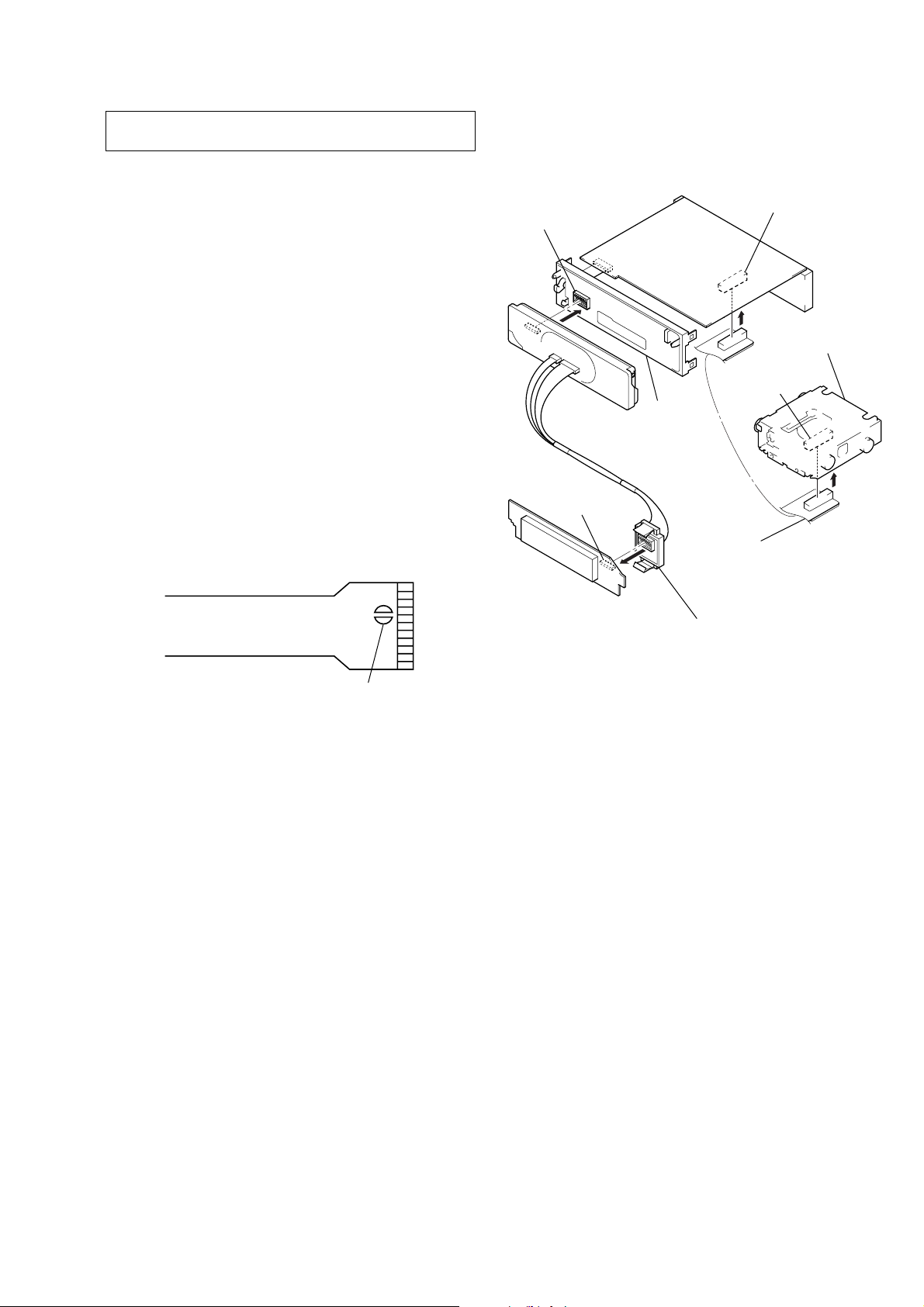
SERVICE POSITION
In checking the key board and main board, prepare two jigs
(connection cable J-2502-011-1 and
connection cable for F/P to main J-2502-071-1).
sub board
(CN801)
key board
(CN900)
sub panel
assy
connect jig
(connection cable J-2502-011-1)
to the main board (CNP500) and
servo board (CN5).
main board (CNP500)
mechanism deck
servo board
(CN5)
laser-ta
OPTICAL PICK-UP FLEXIBLE BOARD
Notes on chip component replacement
•Never reuse a disconnected chip component.
• Notice that the minus side of a tantalum capacitor may be damaged by heat.
Flexible Circuit Board Repairing
•Keep the temperature of the soldering iron around 270 ˚C during repairing.
• Do not touch the soldering iron on the same conductor of the
circuit board (within 3 times).
• Be careful not to apply force on the conductor when soldering
or unsoldering.
connect jig
(connection cable
for F/P to main J-2502-071-1)
to the key board (CN900) and
sub board (CN801).
3
Page 4
MDX-CA790X
SECTION 2
GENERAL
This section is extracted from
instruction manual.
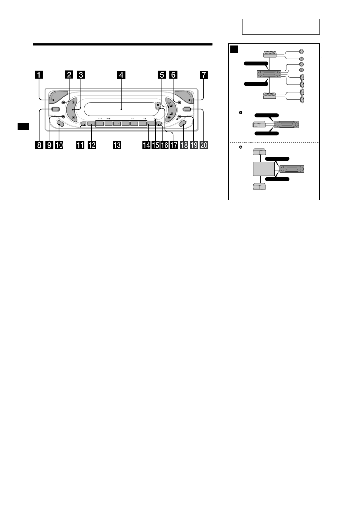
Location of controls
E
C
R
U
O
S
SEL
DSO EQ3
ATT
MODE
AF SENS
a SOURCE (Power on/Radio/CD*1/MD)
button
Selecting the source
b SEL (select) button
Selecting items.
c Volume +/– button
d Display wi
e SEEK +/– b
ndow
utton
To skip tracks, fast-forward, reverse a track,
tune in statio
ns automatically, find a station
manually.
f DSPL (display mode change) button
g OPEN button
h DSO button
i ATT (attenuate) button
j MODE button
Changing the operation
k AF button
l SENS/BTM button
m Number buttons
Radio:
Storing the desired station on each number
button.
1
MD/CD*
:
(1):DISC–*
(2):DISC+*
1
1
(3): REP
(4): SHUF
2
(5):GP*
(6):GP*
/ALBM*3–
2
/ALBM*3+
DISC
BTM REP SHUF
12
O
P
E
D
N
S
P
L
SEEK
LIST
GP/ALBM
3456
PTY TA
OFF
n PTY (programme type) /LIST*
o RESET button (located on the front side of
the unit, behind the front panel)
p TA button
q Z (eject) button (located on the front side
of the unit, behind the front panel)
r OFF (Stop/Power off) button*
s Receptor for the card remote
commander
t EQ3 button
*1 When an optional MD/CD unit is connected.
*2Available only when an MD containing
groups is inserted in this unit.
*3 Available only when an optional CD unit with
the MP3 file control function is connected.
*4
Warning when installing in a car without
an ACC (accessory) position on the
ignition switch
After turning off the ignition, be sure to press
and hold (OFF) on the unit until the display
disappears
Otherwise, the display does not turn off and
.
this causes battery drain.
1
button
4
A
B
2
AUDIO OUT FRONT
AUDIO OUT REAR
BUS AUDIO IN
BUS CONTROL IN
BUS AUDIO IN
Source selector*
Signalquellenwähler*
Sélecteur de source*
Selettore di fonte*
Geluidsbronkiezer*
XA-C30
BUS CONTROL IN
* not supplied
nicht mitgeliefert
non fourni
non in dotazione
niet bijgeleverd
4
4
Page 5
MDX-CA790X
3
BUS AUDIO IN
1
from car aerial
*
1
von Autoantenne
*
AUDIO OUT FRONT
de l’antenne de la voiture
dall’antenna dell’auto
van een auto-antenne
Max. supply current 0.3 A
max. Versorgungsstrom 0,3 A
Courant d’alimentation maximum 0,3 A
Alimentazione massima fornita 0,3 A
Max. voedingsstroom 0,3 A
Cautions
•This unit is designed for negative earth 12 V DC operation only.
•Do not get the wires under a screw, or caught in moving parts
(e.g. seat railing).
•Before making connections, turn the car ignition off to avoid short
circuits.
•Connect the power connecting cord 6 to the unit and speakers
before connecting it to the auxiliary power connector.
•Run all earth wires to a common earth point.
•Be sure to insulate any loose unconnected wires with electrical
tape for safety.
Notes on the power supply cord (yellow)
•When connecting this unit in combination with other stereo
components, the connected car circuit’s rating must be higher than
the sum of each component’s fuse.
•When no car circuits are rated high enough, connect the unit
directly to the battery.
Parts list (1)
•The numbers in the list are keyed to those in the instructions.
•The bracket 1 and the protection collar 4 are attached to the unit
before shipping. Before mounting the unit, use the release keys 7
to remove the bracket 1 and the protection collar 4 from the
unit. For details, see “Removing the protection collar and the
bracket (4)” on the reverse side of the sheet.
• Keep the release keys 7 for the future use as they are also
necessary if you remove the unit from your car.
Caution
Handle the bracket 1 carefully to avoid injuring your fingers.
1
Note
Before installing, make sure that the catches on both sides of the
bracket 1 are bent inwards 2 mm. If the catches are straight or bent
outwards, the unit will not be installed securely and may spring out.
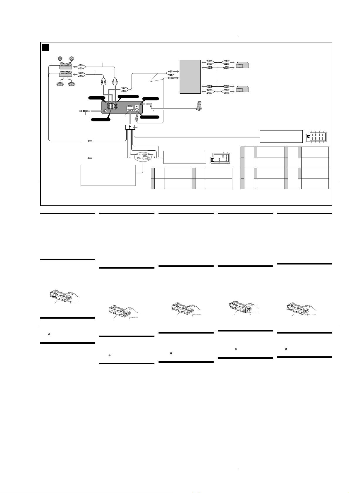
Connection example (2)
Notes (2-A)
• Be sure to connect the earth cord before connecting the amplifier.
•If you connect an optional power amplifier and do not use the
built-in amplifier, the beep sound will be deactivated.
)
Tip (2-B-
For connecting two or more MD/CD changers, the source selector XAC30 (optional) is necessary.
Connection diagram (3)
A
To AMP REMOTE IN of an optional power amplifier
This connection is only for amplifiers. Connecting any other
system may damage the unit.
B
To the interface cable of a car telephone
Warning
If you have a power aerial without a relay box, connecting this unit
with the supplied power connecting cord 6 may damage the aerial.
Notes on the control leads
• The power aerial control lead (blue) supplies +12 V DC when you
turn on the tuner or when you activate the AF (Alternative
Frequency), TA (Traffic Announcement) function.
• When your car has built-in FM/MW/LW aerial in the rear/side glass,
connect the power aerial control lead (blue) or the accessory power
input lead (red) to the power terminal of the existing aerial
booster. For details, consult your dealer.
•A power aerial without a relay box cannot be used with this unit.
Memory hold connection
When the yellow power input lead is connected, power will always
be supplied to the memory circuit even when the ignition switch is
turned off.
Notes on speaker connection
• Before connecting the speakers, turn the unit off.
• Use speakers with an impedance of 4 to 8 ohms, and with
adequate power handling capacities to avoid its damage.
• Do not connect the speaker terminals to the car chassis, or connect
the terminals of the right speakers with those of the left speaker.
• Do not connect the earth lead of this unit to the negative (–)
terminal of the speaker.
• Do not attempt to connect the speakers in parallel.
• Connect only passive speakers. Connecting active speakers (with
built-in amplifiers) to the speaker terminals may damage the unit.
• To avoid a malfunction, do not use the built-in speaker wires
installed in your car if the unit shares a common negative (–) lead
for the right and left speakers.
• Do not connect the unit’s speaker cords to each other.
Note on connection
If speaker and amplifier are not connected correctly, "FAILURE"
appears in the display. In this case, make sure the speaker and
amplifier are connected correctly.
1
*
1
*
1
*
5
A
B
See “Power connection diagram” on the reverse side for details.
Näheres dazu finden Sie im „Stromanschlussdiagramm“.
Blättern Sie dazu bitte um.
Voir le «
Schéma de connexion d’alimentation
plus de détails.
Per ulteriori informazioni, vedere “Schema dei collegamenti di
alimentazione” che si trova sul retro.
Zie "Voedingsaansluitschema" op de achterkant voor meer
details.
Catch
3
*
3
*
Supplied with XA-C30
Mit dem XA-C30 geliefert
Fourni avec le XA-C30
In dotazione con il modello XA-C30
Geleverd met de XA-C30
AUDIO OUT FRONT
AUDIO
AUDIO
BUS
OUT
OUT
AUDIO
REAR
FRONT
IN
Fuse (10 A)
Sicherung (10 A)
AUDIO OUT REAR
AMP REM
ATT
Fusible (10 A)
Fusibile (10 A)
Zekering (10 A)
Blue/white striped
Blauweiß gestreift
Rayé bleu/blanc
A strisce blu e bianche
Blauw/wit gestreept
Light blue
Hellblau
Bleu ciel
Azzurro
Hemelsblauw
» au verso pour
Vorsicht
•Dieses Gerät ist ausschließlich für den Betrieb bei 12 V
Gleichstrom (negative Erdung) bestimmt.
•Achten Sie darauf, dass die Kabel nicht unter einer Schraube oder
zwischen beweglichen Teilen wie z. B. in einer Sitzschiene
eingeklemmt werden.
•Schalten Sie, bevor Sie irgendwelche Anschlüsse vornehmen, die
Zündung des Fahrzeugs aus, um Kurzschlüsse zu vermeiden.
•Verbinden Sie das Stromversorgungskabel 6 mit dem Gerät und
den Lautsprechern, bevor Sie es mit dem Hilfsstromanschluss
verbinden.
•Schließen Sie alle Erdungskabel an einen gemeinsamen
Massepunkt an.
•Aus Sicherheitsgründen müssen alle losen, nicht angeschlossenen
Drähte mit Isolierband isoliert werden.
Hinweise zum Stromversorgungskabel (gelb)
•Wenn Sie dieses Gerät zusammen mit anderen Stereokomponenten
anschließen, muss der Autostromkreis, an den die Geräte
angeschlossen sind, eine höhere Leistung aufweisen als die Summe der
Sicherungen der einzelnen Komponenten.
•Wenn kein Autostromkreis eine so hohe Leistung aufweist, schließen
Sie das Gerät direkt an die Batterie an.
Teileliste (1)
•Die Nummern in der Liste sind dieselben wie im Erläuterungstext.
•Die Halterung 1 und die Schutzumrandung 4 werden vor dem
Ausliefern am Gerät angebracht. Bevor Sie das Gerät montieren,
nehmen Sie die Halterung 1 und die Schutzumrandung 4
mithilfe der Löseschlüssel 7 bitte vom Gerät ab. Einzelheiten
dazu finden Sie unter „Abnehmen der Schutzumrandung und der
Halterung (4)” auf der Rückseite dieses Blattes.
•Bewahren Sie die Löseschlüssel 7 für den späteren Gebrauch
auf. Sie werden z. B. benötigt, wenn Sie das Gerät aus dem
Fahrzeug ausbauen wollen.
Sicherheitshinweis
Seien Sie beim Umgang mit der Halterung 1 vorsichtig, damit Sie
sich nicht die Hände verletzen.
1
Hinweis
Vergewissern Sie sich vor dem Installieren, dass die Verriegelungen
an beiden Seiten der Halterung 1 um 2 mm nach innen gebogen
sind. Wenn die Verriegelungen gerade oder nach außen gebogen
sind, lässt sich das Gerät nicht sicher installieren und kann
herausspringen.
Anschlussbeispiel (2)
Hinweise (2-A)
• Schließen Sie unbedingt zuerst das Massekabel an, bevor Sie den
Verstärker anschließen.
• Wenn Sie einen gesondert erhältlichen Endverstärker anschließen und
den integrierten Verstärker nicht benutzen, wird der Signalton
deaktiviert.
Tipp (2-B- )
Zum Anschließen von zwei oder mehr MD/CD-Wechslern wird der
gesondert erhältliche Signalquellenwähler XA-C30 benötigt .
Anschlussdiagramm (3)
A
An AMP REMOTE IN des gesondert erhältlichen Endverstärkers
Dieser Anschluss ist ausschließlich für Verstärker gedacht.
Schließen Sie nichts anderes daran an. Andernfalls kann das Gerät
beschädigt werden.
B
An Schnittstellenkabel eines Autotelefons
Warnung
Wenn Sie eine Motorantenne ohne Relaiskästchen verwenden, kann
durch Anschließen dieses Geräts mit dem mitgelieferten
Stromversorgungskabel 6 die Antenne beschädigt werden.
Hinweise zu den Steuerleitungen
• Die Motorantennen-Steuerleitung (blau) liefert + 12 V Gleichstrom,
wenn Sie den Tuner einschalten oder die AF- (Alternativfrequenzsuche)
oder die TA-Funktion (Verkehrsdurchsagen) aktivieren.
• Wenn das Fahrzeug mit einer in der Heck-/Seitenfensterscheibe
integrierten FM (UKW)/MW/LW-Antenne ausgestattet ist, schließen Sie
die Motorantennen-Steuerleitung (blau) oder die
Zubehörstromversorgungsleitung (rot) an den
Stromversorgungsanschluss des vorhandenen Antennenverstärkers an.
Näheres dazu erfahren Sie bei Ihrem Händler.
• Es kann nur eine Motorantenne mit Relaiskästchen angeschlossen
werden.
Stromversorgung des Speichers
Wenn die gelbe Stromversorgungsleitung angeschlossen ist, wird der
Speicher stets (auch bei ausgeschalteter Zündung) mit Strom versorgt.
Hinweise zum Lautsprecheranschluss
• Schalten Sie das Gerät aus, bevor Sie die Lautsprecher anschließen.
• Verwenden Sie Lautsprecher mit einer Impedanz zwischen 4 und 8 Ohm
und ausreichender Belastbarkeit. Ansonsten können die Lautsprecher
beschädigt werden.
• Verbinden Sie die Lautsprecheranschlüsse nicht mit dem Wagenchassis
und verbinden Sie auch nicht die Anschlüsse des rechten mit denen des
linken Lautsprechers.
• Verbinden Sie die Masseleitung dieses Geräts nicht mit dem negativen
(–) Lautsprecheranschluss.
• Versuchen Sie nicht, Lautsprecher parallel anzuschließen.
• An die Lautsprecheranschlüsse dieses Geräts dürfen nur
Passivlautsprecher angeschlossen werden. Schließen Sie keine
Aktivlautsprecher (Lautsprecher mit eingebauten Verstärkern) an, da das
Gerät sonst beschädigt werden könnte.
• Um Fehlfunktionen zu vermeiden, verwenden Sie nicht die im Fahrzeug
installierten, integrierten Lautsprecherleitungen, wenn am Ende eine
gemeinsame negative (–) Leitung für den rechten und den linken
Lautsprecher verwendet wird.
• Verbinden Sie nicht die Lautsprecherkabel des Geräts miteinander.
Hinweis zum Anschließen
Wenn Lautsprecher und Verstärker nicht richtig angeschlossen sind,
erscheint “FAILURE” im Display. Vergewissern Sie sich in diesem Fall, dass
Lautsprecher und Verstärker richtig angeschlossen sind.
Verriegelung
REMOTE IN
2
*
BUS CONTROL IN
6
Yellow
Gelb
Jaune
4
Giallo
Geel
Blue
Blau
5
Bleu
Blu
Blauw
Positions 1, 2, 3 and 6 do not have pins.
An Position 1, 2, 3 und 6 befinden sich keine Stifte.
Les positions 1, 2, 3 et 6 ne comportent pas de broches.
Le posizioni 1, 2, 3 e 6 non hanno piedini.
De posities 1, 2, 3 en 6 hebben geen pins.
Précautions
•Cet appareil est conçu pour fonctionner sur un courant continu de
12 V avec une masse négative uniquement.
•Evitez de fixer des vis sur les câbles ou de coincer ceux-ci dans des
pièces mobiles (par exemple, armature de siège).
•Avant d’effectuer des raccordements, éteignez le moteur pour
éviter les courts-circuits.
•Branchez le cordon d’alimention 6 sur l’appareil et les hautparleurs avant de le brancher sur le connecteur d’alimentation
auxiliaire.
•Rassemblez tous les fils de terre en un point de masse
commun.
•Par mesure de sécurité, veillez à isoler tout fil ou câble non
connecté avec du chatterton.
Remarques sur le cordon d’alimentation (jaune)
•Lorsque cet appareil est raccordé à d’autres appareils stéréo, la
valeur nominale des circuits de la voiture raccordée doit être
supérieure à la somme des fusibles de chaque appareil.
•Si aucun circuit de la voiture n’est assez puissant, raccordez
directement l’appareil à la batterie.
Liste des composants (1)
•Les numéros de la liste correspondent à ceux des instructions.
•Le support 1 et le tour de protection 4 sont fixés à l’appareil
avant de quitter l’usine. Avant le montage de l’appareil, utilisez
les clés de déblocage 7 pour détacher le support 1 et le tour de
protection 4 de l’appareil. Pour de plus amples informations,
reportez-vous à la section « Retrait du tour de protection et du
support (4) » au verso de la feuille.
• Conservez les clés de déblocage 7 pour une utilisation
ultérieure car vous en aurez également besoin pour retirer
l’appareil de votre véhicule.
Précaution
Manipulez précautionneusement le support 1 pour éviter de vous
blesser aux doigts.
Remarque
Avant l’installation, assurez-vous que les loquets des deux côtés du
support 1 sont bien pliés de 2 mm vers l’intérieur. Si les loquets sont
droits ou pliés vers l’extérieur, l’appareil ne peut pas être fixé
solidement et peut se détacher.
Exemple de raccordement (2)
Remarques (2-A)
• Raccordez d’abord le fil de masse avant de connecter
l’amplificateur.
•Si vous raccordez un amplificateur de puissance en option et que
vous n’utilisez pas l’amplificateur intégré, le bip sonore est
désactivé.
Conseil (2-B-
Dans le cas du raccordement de deux changeurs de MD/CD ou plus, le
sélecteur de source XA-C30 (en option) est indispensable.
Schéma de raccordement (3)
A
Au niveau du AMP REMOTE IN d’un amplificateur de puissance
en option
Ce raccordement existe seulement pour les amplificateurs. Le
raccordement à tout autre système peut endommager l’appareil.
B
Vers le câble d’interface d’un téléphone de voiture
Avertissement
Si vous disposez d’une antenne électrique sans boîtier de relais, le
branchement de cet appareil au moyen du cordon d’alimentation fourni
6 risque d’endommager l’antenne.
Remarques sur les fils de commande
• Le fil de commande (bleu) fournit du courant continu de +12 V
lorsque vous allumez le sélecteur de canaux ou lorsque vous activez
la fonction TA (messages de radioguidage) en AF (fréquence
alternative).
• Lorsque votre voiture est équipée d’une antenne FM/MW/LW
intégrée dans la vitre arrière/latérale, raccordez le fil de commande
de l’antenne (bleu) ou l’entrée d’alimentation des accessoires
(rouge) à la borne de l’amplificateur d’antenne existant. Pour plus
de détails, consultez votre revendeur.
• Une antenne électrique sans boîtier de relais ne peut pas être
utilisée avec cet appareil.
Raccordement pour la conservation de la mémoire
Lorsque le fil d’entrée d’alimentation jaune est connecté, le circuit de
la mémoire est alimenté en permanence même si la clé de contact est
en position d’arrêt.
Remarques sur le raccordement des haut-parleurs
• Avant de raccorder les haut-parleurs, mettre l’appareil hors tension.
• Utiliser des haut-parleurs ayant une impédance de 4 à 8 ohms et une
capacité adéquate sous peine de les endommager.
• Ne pas raccorder les bornes du système de haut-parleurs au châssis de la
voiture et ne pas connecter les bornes du haut-parleur droit à celles du
haut-parleur gauche.
• Ne pas raccorder le câble de masse de cet appareil à la borne négative
(–) du haut-parleur.
• Ne pas tenter de raccorder les haut-parleurs en parallèle.
• Ne pas connecter d’enceintes actives (avec amplificateurs intégrés) aux
bornes d’enceinte de cet appareil, pour éviter d’endommager l’appareil.
Veiller à raccorder des enceintes passives uniquement.
• Pour éviter tout dysfonctionnement, ne pas utiliser les fils des hautparleurs intégrés installés dans votre voiture si l’appareil dispose d’un fil
négatif commun (–) pour les haut-parleurs droit et gauche.
• Ne pas raccorder entre eux les cordons des haut-parleurs de l’appareil.
Remarque sur le raccordement
Si les enceintes et l’amplificateur ne sont pas raccordés correctement,
le message « FAILURE » s’affiche. Dans ce cas, assurez-vous que les
enceintes et l’amplificateur sont raccordés correctement.
Source selector (not
supplied)
Signalquellenwähler
(nicht mitgeliefert)
Sélecteur de source
(non fourni)
Selettore di fonte
(non in dotazione)
Geluidsbronkiezer
(niet bijgeleverd)
XA-C30
from the car’s power connector
vom Stromanschluss des Fahrzeugs
du connecteur d’alimentation de la voiture
dal connettore di alimentazione dell’auto
van de autovoedingsstekker
continuous power supply
permanente Stromversorgung
alimentation continue
alimentazione continua
continu voeding
power aerial control
Motorantennensteuerung
commande d’antenne électrique
comando dell’antenna elettrica
automatische antenne
7
8
1
)
Supplied with the MD/CD changer
Mit dem MD/CD-Wechsler geliefert
Fourni avec le changeur de MD/CD
In dotazione con il cambia MD/CD
Geleverd met de MD/CD-wisselaar
Red
switched power supply
Rot
geschaltete Stromversorgung
Rouge
alimentation commutée
Rosso
alimentazione commutata
Rood
geschakelde voeding
Black
Schwarz
Noir
Nero
Zwart
*1Note for the aerial connecting
If your car aerial is an ISO (International
Organisation for Standardisation) type,
use the supplied adaptor 5 to connect it.
First connect the car aerial to the supplied
adaptor, then connect it to the aerial jack
of the master unit.
2
Insert with the cord downwards
*
3
RCA pin cord (not supplied)
*
1
Hinweis zum Anschließen der Antenne
*
Wenn Ihre Fahrzeugantenne der
ISO-Norm (ISO = International
Organization for Standardization Internationale Normungsgemeinschaft)
entspricht, schließen Sie sie mithilfe des
mitgelieferten Adapters 5 an.
Verbinden Sie zuerst die Fahrzeugantenne
mit dem mitgelieferten Adapter und
verbinden Sie diesen dann mit der
Antennenbuchse des Hauptgeräts.
2
Mit dem Kabel nach unten einstecken
*
3
Cinchkabel (nicht mitgeliefert)
*
1
*
Remarque sur le raccordement de
l’antenne
Si votre antenne de voiture est de type
ISO (Organisation internationale de
normalisation), utilisez l’adaptateur fourni
5 pour la raccorder.
Raccordez d’abord l’antenne de voiture à
l’adaptateur fourni et, ensuite, à la prise
d’antenne de l’appareil principal.
2
Insérez avec le câble vers le bas
*
3
Cordon à broche RCA (non fourni)
*
from the car’s speaker connector
vom Lautsprecheranschluss des Fahrzeugs
du connecteur de haut-parleur de la voiture
dal connettore del diffusore dell’auto
van de autoluidsprekerstekker
Speaker, Rear, Right
57
48
earth
Masse
masse
terra
aarding
Attenzione
•Questo apparecchio è stato progettato per l’uso solo a 12 V CC con
massa negativa.
•Evitare che i cavi rimangano bloccati da una vite o incastrati nelle
parti mobili (ad esempio nelle guide scorrevoli dei sedili).
•Prima di effettuare i collegamenti, spegnere il motore
dell’automobile onde evitare di causare cortocircuiti.
•Collegare il cavo di collegamento dell’alimentazione 6
all’apparecchio e ai diffusori prima di collegarlo al connettore di
alimentazione ausiliaria.
•Portare tutti i cavi di massa a un punto di massa comune.
•Per sicurezza, assicurarsi di isolare qualsiasi cavo non collegato
mediante apposito nastro.
Note sul cavo di alimentazione (giallo)
•Se questo apparecchio viene collegato in combinazione con altri
componenti stereo, la potenza nominale dei circuiti
dell’automobile collegati deve essere superiore a quella prodotta
dalla somma dei fusibili di ciascun componente.
•Se la potenza nominale dei circuiti dell’automobile non è
sufficiente, collegare l’apparecchio direttamente alla batteria.
Elenco dei componenti (1)
•I numeri nella lista corrispondono a quelli riportati nelle
istruzioni.
•La staffa 1 e la cornice di protezione 4 vengono applicati
all’unità in fabbrica. Prima di installare l’unità, utilizzare le chiavi
di rilascio 7 per rimuovere la staffa 1 e la cornice di protezione
4 dall’apparecchio. Per ulteriori informazioni, vedere
“Rimozione della staffa e della cornice di protezione (4)” sul lato
opposto del foglio.
• Conservare le chiavi di rilascio 7 per un uso futuro in quanto
sono necessarie per rimuovere l’unità dall’auto.
Attenzione
Maneggiare la staffa 1 con cautela per evitare di ferirsi le mani.
Nota
Prima di installare l’unità, accertarsi di ripiegare i fermi presenti su
entrambi i lati della staffa 1 verso l’interno di 2 mm. Se i fermi sono
diritti o ripiegati verso l’esterno, l’apparecchio non verrà installato in
modo sicuro e potrebbe non essere saldo.
Esempi di collegamento (2)
Note (2-A)
• Assicurarsi di collegare il cavo di terra prima di collegare
l’apparecchio all’amplificatore.
• Se si collega un amplificatore di potenza opzionale e non si utilizza
l’amplificatore incorporato, il segnale acustico verrà disattivato.
Suggerimento (2-B-
Per collegare due o più cambia MD/CD, si deve utilizzare il selettore
di fonte XA-C30 (opzionale).
Schema di collegamento (3)
A
A AMP REMOTE IN di un amplificatore di potenza opzionale
Questo collegamento è riservato esclusivamente agli
amplificatori. Non collegare un tipo di sistema diverso onde
evitare di causare danni all’apparecchio.
B
Al cavo di interfaccia di un telefono per auto
Avvertenza
Quando si collega l’apparecchio con il cavo di alimentazione in
dotazione 6, si potrebbe danneggiare l’antenna elettrica se questa
non ha la scatola a relè.
Note sui cavi di controllo
• Il cavo (blu) di controllo dell’antenna elettrica fornisce
alimentazione pari a +12 V CC quando si attiva il sintonizzatore o
le funzioni TA (notiziario sul traffico) e AF (frequenza alternativa).
• Se l’automobile è dotata di antenna FM/MW/LW incorporata nel
vetro posteriore/laterale, collegare il cavo (blu) di controllo
dell’antenna elettrica o il cavo (rosso) di ingresso
dell’alimentazione ausiliaria al terminale di alimentazione del
preamplificatore dell’antenna esistente. Per ulteriori informazioni,
consultare il proprio fornitore.
• Non è possibile usare un’antenna elettrica senza scatola a relè con
questo apparecchio.
Collegamento per la conservazione della memoria
Quando il cavo di ingresso alimentazione giallo è collegato, viene
sempre fornita alimentazione al circuito di memoria anche quando
l’interruttore di accensione è spento.
Note sul collegamento dei diffusori
• Prima di collegare i diffusori spegnere l’apparecchio.
• Usare diffusori di impedenza compresa tra 4 e 8 ohm e con capacità
di potenza adeguata, onde evitare che vengano danneggiati.
• Non collegare i terminali del sistema diffusori al telaio dell’auto e
non collegare i terminali del diffusore destro a quelli del diffusore
sinistro.
• Non collegare il cavo di terra di questo apparecchio al terminale
negativo (–) del diffusore.
• Non collegare i diffusori in parallelo.
• Assicurarsi di collegare soltanto diffusori passivi, poiché il
collegamento di diffusori attivi, dotati di amplificatori incorporati,
ai terminali dei diffusori potrebbe danneggiare l’apparecchio.
• Per evitare problemi di funzionamento, non utilizzare i cavi dei
diffusori incorporati installati nell’automobile se l’apparecchio
condivide un cavo comune negativo (–) per i diffusori destro e
sinistro.
• Non collegare fra loro i cavi dei diffusori dell’apparecchio.
Nota sui collegamenti
Se l’amplificatore e il diffusore non sono collegati correttamente,
“FAILURE” viene visualizzato nel display. In tal caso, accertarsi che
l’amplificatore e il diffusore siano collegati correttamente.
1
2
3
4
Negative polarity positions 2, 4, 6, and 8 have striped cords.
An den negativ gepolten Positionen 2, 4, 6 und 8 befinden sich gestreifte Adern.
Les positions de polarité négative 2, 4, 6 et 8 sont dotées de cordons rayés.
Le posizioni a polarità negativa 2, 4, 6 e 8 hanno cavi rigati.
De posities voor negatieve polariteit (2, 4, 6 en 8) hebben gestreepte kabels.
1
)
Purple
Violett
Mauve
Grigio
Viola
Paars
Grey
Grau
Gris
Grijs
Fermo
Lautsprecher hinten rechts
haut-parleur, arrière, droit
+
Diffusore, posteriore, destro
Luidspreker, achter, rechts
Speaker, Rear, Right
Lautsprecher hinten rechts
haut-parleur, arrière, droit
–
Diffusore, posteriore, destro
Luidspreker, achter, rechts
Speaker, Front, Right
Lautsprecher vorne rechts
haut-parleur, avant, droit
+
Diffusore, anteriore, destro
Luidspreker, voor, rechts
Speaker, Front, Right
Lautsprecher vorne rechts
haut-parleur, avant, droit
–
Diffusore, anteriore, destro
Luidspreker, voor, rechts
*1Nota per il collegamento dell’antenna
Se l’antenna dell’auto è di tipo ISO
(International Organization
Standardization), utilizzare l’adattatore 5
in dotazione per collegarla.
Collegare prima l’antenna della macchina
all’adattatore in dotazione, quindi
collegarla alla presa dell’antenna
dell’apparecchio principale.
2
Inserire con il cavo verso il basso
*
3
*
Cavo a piedini RCA (non in dotazione)
1
*
Opmerking bij de antenne-aansluiting
Indien uw auto is uitgerust met een
antenne van het type ISO (International
Organisation for Standardization), moet u
die aansluiten met behulp van de
meegeleverde adapter 5.
Sluit eerst de auto-antenne aan op de
meegeleverde adapter en vervolgens de
antennestekker op het hoofdtoestel.
2
Plaatsen met het snoer naar beneden
*
3
Tulpstekkersnoer (niet bijgeleverd)
*
13 57
24 68
Speaker, Front, Left
White
Weiß
Blanc
Bianco
Wit
Green
Grün
Vert
Verde
Groen
1
Lautsprecher vorne links
haut-parleur, avant, gauche
+
Diffusore, anteriore, sinistro
Luidspreker, voor, links
Speaker, Front, Left
Lautsprecher vorne links
haut-parleur, avant, gauche
–
Diffusore, anteriore, sinistro
Luidspreker, voor, links
Speaker, Rear, Left
Lautsprecher hinten links
haut-parleur, arrière, gauche
+
Diffusore, posteriore, sinistro
Luidspreker, achter, links
Speaker, Rear, Left
Lautsprecher hinten links
haut-parleur, arrière, gauche
–
Diffusore, posteriore, sinistro
Luidspreker, achter, links
GreepLoquet
5
6
7
8
Let op!
•Dit apparaat is ontworpen voor gebruik op gelijkstroom van een
12 Volts auto-accu, negatief geaard.
•Zorg ervoor dat de draden niet onder een schroef of tussen
bewegende onderdelen (b.v. zetelrail) terechtkomen.
•Alvorens aansluitingen te verrichten moet u het contact uitzetten
om kortsluiting te vermijden.
•Sluit het netsnoer 6 aan op het toestel en de luidsprekers
vooraleer u het op de hulpvoedingsaansluiting aansluit.
•Sluit alle aarddraden op een gemeenschappelijk aardpunt aan.
•Voorzie niet aangesloten draden om veiligheidsredenen altijd van
isolatietape.
Opmerkingen bij de voedingskabel (geel)
•Wanneer u dit toestel aansluit samen met andere componenten,
moet het vermogen van de aangesloten autostroomkring groter
zijn dan de som van de zekeringen van elke component
afzonderlijk.
•Wanneer het vermogen ontoereikend is, moet u het toestel
rechtstreeks aansluiten op de accu.
Onderdelenlijst (1)
•De nummers in de afbeelding verwijzen naar die in de montageaanwijzingen.
•De beugel 1 en de beschermende rand 4 worden bevestigd op
het toestel voordat dit wordt verzonden. Voordat u het toestel
plaatst, moet u de ontgrendelingssleutels 7 gebruiken om de
beugel 1 en de beschermende rand 4 te verwijderen van het
toestel. Zie "De beschermende rand en de beugel verwijderen
(4)" aan de achterzijde van dit vel voor meer informatie.
• Bewaar de ontgrendelingssleutels 7 voor toekomstig gebruik
omdat u deze ook nodig hebt om het toestel uit de auto te
verwijderen.
Opgelet
Houd de beugel 1 voorzichtig vast zodat u uw vingers niet
verwondt.
Opmerking
Voordat u het toestel installeert, moet u de grepen aan beide zijden
van de beugel 1 2 mm naar binnen buigen. Als de grepen recht zijn
of naar buiten gebogen, kan het toestel niet goed worden bevestigd
en kan dit losschieten.
Voorbeeldaansluitingen (2)
Opmerkingen (2-A)
•Sluit eerst de massakabel aan alvorens de versterker aan te sluiten.
•Als u een los verkrijgbare vermogensversterker aansluit en de
ingebouwde versterker niet gebruikt, is de pieptoon uitgeschakeld.
)
Tip (2-B-
Om twee of meer MD/CD-wisselaars aan te sluiten, hebt u de
geluidsbronkiezer XA-C30 (optioneel) nodig.
Aansluitschema (3)
A
Naar AMP REMOTE IN van een los verkrijgbare
vermogensversterker
Deze aansluiting is alleen bedoeld voor versterkers. Door een
ander systeem aan te sluiten kan het toestel worden beschadigd.
B
Naar het interface-snoer van een autotelefoon
Opgelet
Indien u een elektrische antenne heeft zonder relaiskast, kan het
aansluiten van deze eenheid met het bijgeleverde netsnoer 6 de
antenne beschadigen.
Opmerking betreffende de aansluitsnoeren
• De antennevoedingskabel (blauw) levert +12 V gelijkstroom
wanneer u de tuner inschakelt of de AF (Alternative Frequency), TA
(Traffic Announcement) functie activeert.
•Wanneer uw auto is uitgerust met een FM/MW/LW-antenne in de
achterruit/voorruit, moet u de antennevoedingskabel (blauw) of de
hulpvoedingskabel (rood) aansluiten op de voedingsingang van de
bestaande antenneversterker. Raadpleeg uw dealer voor meer
details.
• Met dit apparaat is het niet mogelijk een automatische antenne
zonder relaiskast te gebruiken.
Instandhouden van het geheugen
Zolang de gele stroomdraad is aangesloten, blijft de
stroomvoorziening van het geheugen intact, ook wanneer het
contact van de auto wordt uitgeschakeld.
Opmerkingen betreffende het aansluiten van de luidsprekers
• Zorg dat het apparaat is uitgeschakeld, alvorens de luidsprekers
aan te sluiten.
• Gebruik luidsprekers met een impedantie van 4 tot 8 Ohm en let
op dat die het vermogen van de versterker kunnen verwerken. Als
dit wordt verzuimd, kunnen de luidsprekers ernstig beschadigd
raken.
• Verbind in geen geval de aansluitingen van de luidsprekers met het
chassis van de auto en sluit de aansluitingen van de rechter en
linker luidspreker niet op elkaar aan.
• Verbind de massakabel van dit toestel niet met de negatieve (–)
aansluiting van de luidspreker.
• Probeer nooit de luidsprekers parallel aan te sluiten.
•Sluit geen actieve luidsprekers (met ingebouwde versterkers) aan
op de luidspreker-aansluiting van dit apparaat. Dit zal leiden tot
beschadiging van de actieve luidsprekers. Sluit dus altijd uitsluitend
luidsprekers zonder ingebouwde versterker aan.
• Om defecten te vermijden mag u de bestaande
luidsprekerbedrading in uw auto niet gebruiken wanneer er een
gemeenschappelijke negatieve (–) draad is voor de rechter en
linker luidsprekers.
• Verbind de luidsprekerdraden niet met elkaar.
Opmerking over aansluiten
Als de luidspreker en versterker niet correct zijn aangesloten, wordt
"FAILURE" in het display weergegeven. In dit geval moet u zorgen
dat de luidspreker en versterker correct zijn aangesloten.
5
Page 6
MDX-CA790X
4
1
7 7
2
4
Orient the release key
correctly.
Richten Sie den
Löseschlüssel korrekt aus.
Orientez correctement la
clé de déblocage.
Orientare la chiave di
rilascio nel modo corretto.
Plaats de
ontgrendelingssleutel op
de juiste manier.
1
5 23
1
c
Face the hook inwards.
1
1
8
2
m
m
5
3
m
m
claws
Klammern
griffes
Morsetti
klemhaken
Der Haken muss nach innen
weisen.
Tournez le crochet vers
l’intérieur.
Con il gancetto rivolto verso
l’interno.
Het haakje moet naar binnen
wijzen.
c
c
Dashboard
Armaturenbrett
Tableau de bord
Cruscotto
Dashboard
1
4
Fire wall
Motorraumtrennwand
Paroi ignifuge
Parete tagliafiamma
Brandschot
2
3
6 AB
A
B
c
1
2
Precautions
•Choose the installation location carefully so that the
unit will not interfere with normal driving operations.
•Avoid installing the unit in areas subject to dust, dirt,
excessive vibration, or high temperature, such as in
direct sunlight or near heater ducts.
•Use only the supplied mounting hardware for a safe
and secure installation.
Mounting angle adjustment
Adjust the mounting angle to less than 30°.
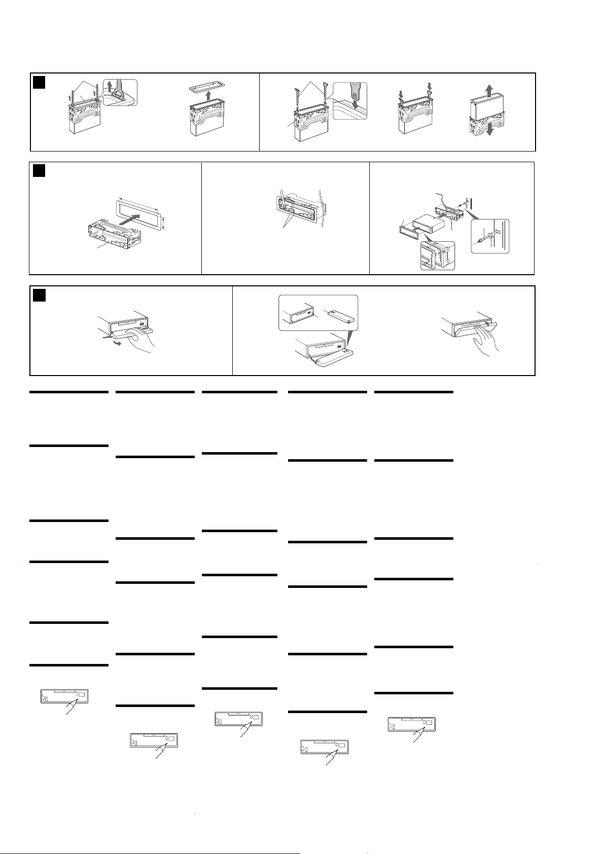
Removing the protection collar
and the bracket (4)
Before installing the unit, remove the protection
collar 4 and the bracket 1 from the unit.
1
Remove the protection collar 4.
1 Engage the release keys 7 together with the
protection collar 4.
2 Pull out the release keys 7 to remove the
protection collar 4.
2
Remove the bracket 1.
1 Insert both release keys 7 together between the
unit and the bracket 1 until they click.
2 Pull down the bracket 1, then pull up the unit to
separate.
Mounting example (5)
Installation in the dashboard
Notes
• Bend these claws outward for a tight fit, if necessary
(5-2).
•Make sure that the 4 catches on the protection collar
4 are properly engaged in the slots of the unit (5-3).
How to detach and attach the
front panel (6)
Before installing the unit, detach the front panel.
6-A To detach
Before detaching the front panel, be sure to press (OFF).
Press (OPEN), then slide the front panel to the right
side, and pull out the left side.
6-B To attach
Place the hole A in the front panel onto the spindle B
on the unit as illustrated, then push the left side in.
Warning when installing in a car
without ACC (accessory) position
on the ignition key switch
After turning off the ignition, be sure to press and
hold (OFF) on the unit until the display disappears.
Otherwise, the display does not turn off and this causes
battery drain.
RESET button
When the installation and connections are completed, be
sure to press the RESET button with a ballpoint pen,
etc., after detaching the front panel.
Vorsichtsmaßnahmen
•Wählen Sie den Einbauort sorgfältig so aus, dass das
Gerät beim Fahren nicht hinderlich ist.
•Bauen Sie das Gerät so ein, dass es keinen hohen
Temperaturen (keinem direkten Sonnenlicht, keiner
Warmluft von der Heizung), keinem Staub, keinem
Schmutz und keinen starken Vibrationen ausgesetzt
ist.
•Für eine sichere Befestigung verwenden Sie stets nur
die mitgelieferten Montageteile.
Hinweis zum Montagewinkel
Das Gerät sollte in einem Winkel von weniger als 30°
montiert werden.
Abnehmen der Schutzumrandung
und der Halterung (4)
Nehmen Sie vor dem Installieren des Geräts die
Schutzumrandung 4 und die Halterung 1 vom
Gerät ab.
1
Entfernen Sie die Schutzumrandung 4.
1 Setzen Sie beide Löseschlüssel 7 an der
Schutzumrandung 4 an.
2 Ziehen Sie die Schutzumrandung 4 mithilfe der
Löseschlüssel 7 heraus.
2
Entfernen Sie die Halterung 1.
1 Führen Sie beide Löseschlüssel 7 zwischen dem
Gerät und der Halterung 1 ein, bis sie mit einem
Klicken einrasten.
2 Ziehen Sie die Halterung 1 nach unten und das
Gerät nach oben, um die beiden zu trennen.
Montagebeispiel (5)
Installation im Armaturenbrett
Hinweise
• Falls erforderlich, diese Klammern für einen sicheren
Halt hochbiegen (5-2).
• Achten Sie darauf, die 4 Verriegelungen an der
Schutzumrandung 4 korrekt in die Aussparungen am
Gerät einzusetzen (5-3).
Abnehmen und Anbringen der
Frontplatte (6)
Nehmen Sie die Frontplatte vor dem Einbau des
Geräts ab.
6-A Abnehmen
Schalten Sie das Gerät vor dem Abnehmen der
Frontplatte unbedingt mit (OFF) aus. Drücken Sie
(OPEN) und ziehen Sie sie auf sich zu heraus.
6-B Anbringen
Setzen Sie Teil A der Frontplatte wie in der Abbildung
dargestellt an Teil B des Geräts an und drücken Sie die
linke Seite der Frontplatte an, bis sie mit einem Klicken
einrastet.
Warnhinweis zur Installation des
Geräts in einem Auto mit
Zündschloss ohne Zubehörposition
ACC oder I
Nachdem Sie die Zündung ausgeschaltet haben,
halten Sie am Gerät unbedingt
die Anzeige ausgeblendet wird.
Andernfalls wird die Anzeige nicht ausgeschaltet und
der Autobatterie wird Strom entzogen.
Taste RESET
Wenn Sie das Gerät eingebaut und alle Anschlüsse
vorgenommen haben, müssen Sie die Frontplatte
abnehmen und mit einem Kugelschreiber oder einem
anderen spitzen Gegenstand die Taste RESET drücken.
(OFF)
gedrückt, bis
Précautions
•Choisir soigneusement l’emplacement de
l’installation afin que l’appareil ne gêne pas la
conduite normale du véhicule.
•Eviter d’installer l’appareil dans un endroit exposé à
de la poussière, de la saleté, des vibrations violentes
ou à des températures élevées, comme en plein
soleil ou à proximité d’une bouche d’air chaud.
•Pour garantir un montage sûr, n’utiliser que le
matériel de montage fourni.
Réglage de l’angle de montage
Ajuster l’inclinaison à un angle inférieur à 30°.
Retrait du tour de protection et
du support (4)
Avant d’installer l’appareil, retirez le tour de
protection 4 et le support 1 de l’appareil.
1
Retirez le tour de protection 4.
1 Accrochez les clés de déblocage 7
simultanément dans le tour de protection 4.
2 Tirez sur les clés de déblocage 7 pour retirer le
tour de protection 4.
2
Retirez le support 1.
1 Insérez les deux clés de déblocage 7
simultanément entre l’appareil et le support 1
jusqu’au déclic indiquant qu’elles sont en place.
2 Tirez le support 1 vers le bas, puis tirez
l’appareil vers le haut pour les séparer.
Exemple de montage (5)
Installation dans le tableau de bord
Remarques
• Plier ces griffes pour assurer une prise correcte si
nécessaire (5-2).
• Assurez-vous que les 4 taquets du tour de protection
4 sont correctement insérés dans les fentes de
l’appareil (5-3).
Retrait et pose de la façade
Avant d’installer l’appareil, déposez la façade.
6-A Retrait
Avant de déposer la façade, ne pas oublier d’appuyer
sur (OFF). Appuyer ensuite sur (OPEN), puis faire
glisser la façade vers la droite et extraire le côté
gauche.
6-B Fixation
Fixer la partie A de la façade sur la partie B de
l’appareil, comme indiqué sur l’illustration, puis
appuyer sur le côté gauche jusqu’au déclic
Avertissement en cas
d’installation dans une voiture
dont le contact ne comporte pas
de position ACC (accessoires)
Après avoir coupé le moteur, n’oubliez pas de
(OFF)
maintenir la touche
jusqu’à ce que l’affichage disparaisse.
Sinon, l’affichage n’est pas désactivé et la batterie se
décharge.
Touche RESET
Après avoir retiré la façade, une fois que l’installation
et les raccordements sont terminés, appuyez sur la
touche RESET avec un stylo à bille, etc.
(6)
sur l’appareil enfoncée
Precauzioni
•Scegliere con attenzione la posizione per
l’installazione in modo che l’apparecchio non
interferisca con le operazioni di guida del conducente.
•Evitare di installare l’apparecchio dove sia soggetto ad
alte temperature, come alla luce solare diretta o al
getto di aria calda dell’impianto di riscaldamento, o
dove possa essere soggetto a polvere, sporco e
vibrazioni eccessive.
•Usare solo il materiale di montaggio in dotazione per
un’installazione stabile e sicura.
Regolazione dell’angolo di montaggio
Regolare l’angolo di montaggio in modo che sia
inferiore a 30°.
Rimozione della staffa e della
cornice di protezione (4)
Prima di installare l’apparecchio, rimuovere la
cornice di protezione 4 e la staffa 1
dall’apparecchio.
1
Rimuovere la cornice di protezione 4.
1 Inserire le chiavi di rilascio 7 insieme alla cornice
di protezione 4.
2 Per rimuovere la cornice di protezione 4, estrarre
le chiavi di rilascio 7.
2
Rimuovere la staffa 1.
1 Inserire contemporaneamente entrambe le chiavi
di rilascio 7 tra l’apparecchio e la staffa 1 fino a
che non scattano in posizione.
2 Estrarre la staffa 1, quindi sollevare
l’apparecchio per rimuovere la staffa.
Esempio di montaggio (5)
Installazione nel cruscotto
Note
•Piegare verso l’esterno questi morsetti per
un’installazione più sicura, se necessario (5-2).
• Assicurarsi che i 4 fermi sulla cornice di protezione 4
siano correttamente inseriti negli alloggiamenti
dell’apparecchio (5-3).
Come rimuovere e reinserire il
pannello anteriore (6)
Prima di installare l’apparecchio rimuovere il
pannello anteriore.
6-A Per rimuoverlo
Prima di rimuovere il pannello anteriore, premere
(OFF). Premere (OPEN), quindi fare scorrere il pannello
anteriore verso destra ed estrarne il lato sinistro.
6-B Per reinserirlo
Posizionare il foro A del pannello anteriore nel
mandrino B dell’apparecchio come illustrato, quindi
spingere il lato sinistro del pannello verso l’interno.
Informazioni importanti per quando si
effettua l’installazione su un’auto
sprovvista della posizione
(accessoria)
accensione
Dopo avere spento il motore, assicurarsi di tenere
premuto
(OFF)
sull’apparecchio finché il display non
scompare.
Diversamente, il display non viene disattivato e questo
potrebbe causare lo scaricamento della batteria.
Tasto RESET
Una volta rimosso il pannello anteriore e dopo aver
terminato l’installazione e i collegamenti, assicurarsi di
premere il tasto RESET con la punta di una penna a
sfera e simili.
ACC
sull’interruttore di
Voorzorgsmaatregelen
•Kies de installatieplaats zorgvuldig zodat het toestel
de bestuurder niet hindert tijdens het rijden.
•Installeer het apparaat niet op plaatsen waar het
blootgesteld wordt aan hoge temperaturen, b.v. in
direct zonlicht of bij de warme luchtstroom van de
autoverwarming, aan sterke trillingen, of waar het in
contact komt met veel stof of vuil.
•Gebruik voor het veilig en stevig monteren van het
apparaat uitsluitend de bijgeleverde montageonderdelen.
Maximale montagehoek
Installeer het apparaat nooit onder een hoek van meer
dan 30° met het horizontale vlak.
De beschermende rand en de
beugel verwijderen (4)
Voordat u het toestel gaat installeren, moet u de
beschermende rand 4 en de beugel 1
verwijderen van het toestel.
1
Verwijder de beschermende rand 4.
1 Bevestig de ontgrendelingssleutels 7 op de
beschermende rand 4.
2 Trek de ontgrendelingssleutels 7 naar u toe om
de beschermende rand 4 te verwijderen.
2
Verwijder de beugel 1.
1 Plaats de ontgrendelingssleutels 7 tussen het
toestel en de beugel 1 tot deze vastklikken.
2 Trek de beugel 1 omlaag en trek het toestel
omhoog om deze van elkaar te scheiden.
Montagevoorbeeld (5)
Montage in het dashboard
Opmerkingen
•Indien nodig kunt u deze lipjes ombuigen voor een
steviger bevestiging (5-2).
•De 4 grepen op de beschermende rand 4 moeten
goed in de sleuven van het toestel zijn geplaatst (5-3).
Verwijderen en bevestigen van het
afneembare voorpaneel (6)
Verwijder, alvorens met het installeren te beginnen,
het afneembare voorpaneel.
6-A Verwijderen
Vergeet niet, voordat u het voorpaneel verwijdert, eerst
op (OFF) te drukken. Druk vervolgens op de (OPEN)
toets en trek het naar u toe.
6-B Bevestigen
Breng deel A van het voorpaneel aan op deel B van het
apparaat zoals afgebeeld en druk op de linkerzijde tot
deze vastklikt.
Opgelet bij het monteren in een
auto waarvan het contactslot geen
ACC (accessory) stand heeft
Als de motor is uitgeschakeld, moet u op (OFF)
drukken en deze toets ingedrukt houden tot de
weergave verdwijnt.
Als u dit niet doet, wordt de weergave niet
uitgeschakeld en raakt de batterij uitgeput.
RESET-toets
Na het installeren en verrichten van alle aansluitingen,
moet u altijd het voorpaneel verwijderen en de RESETtoets indrukken met een balpen of dergelijke.
6
Page 7
MDX-CA790X
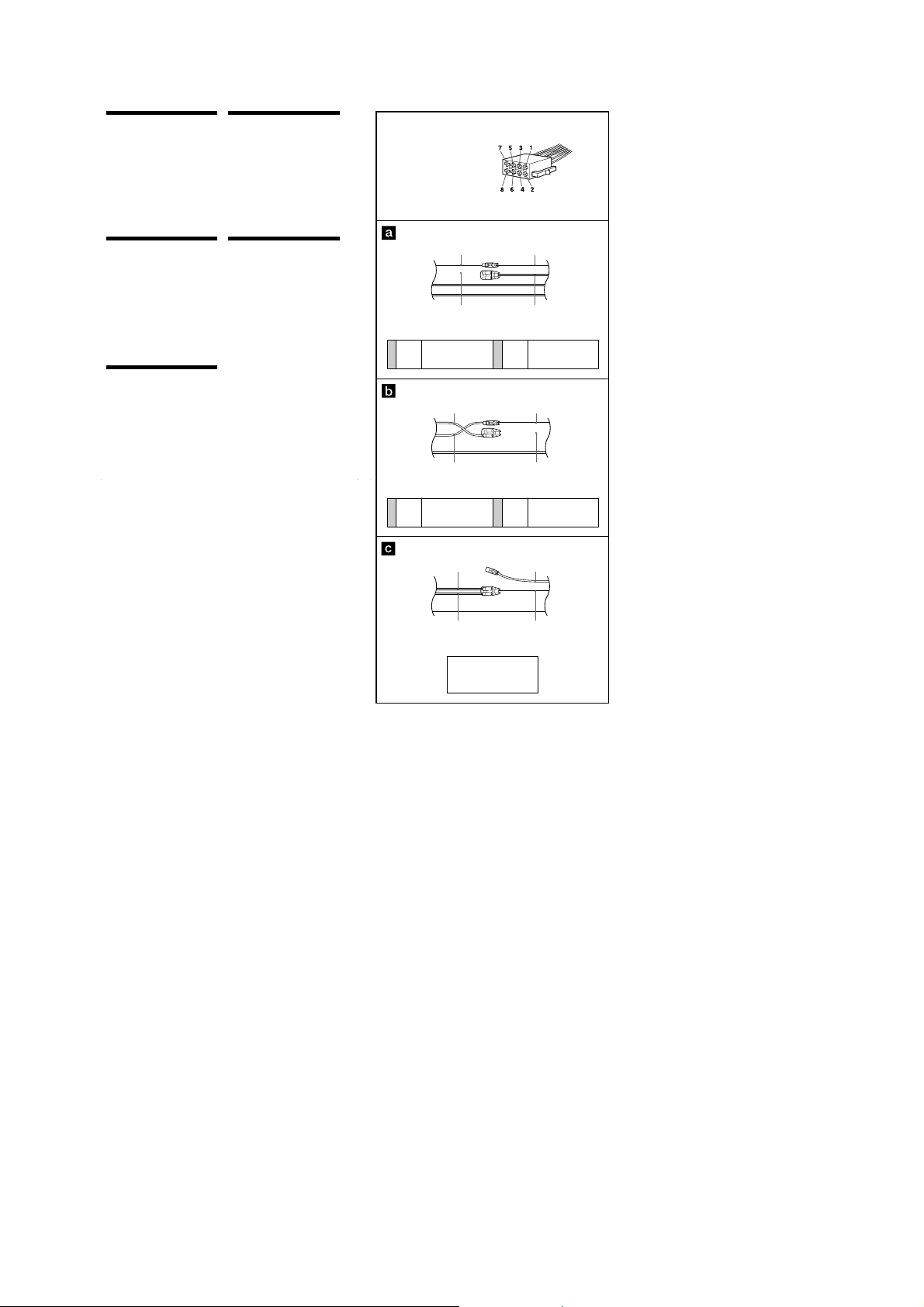
Power connection diagram
Auxiliary power connector may vary depending on
the car. Check your car’s auxiliary power connector
diagram to make sure the connections match
correctly. There are three basic types (illustrated
below). You may need to switch the positions of the
red and yellow leads in the car stereo’s power
connecting cord.
After matching the connections and switched
power supply leads correctly, connect the unit to
the car’s power supply. If you have any questions
and problems connecting your unit that are not
covered in this manual, please consult the car
dealer.
Stromanschlussdiagramm
Der Hilfsstromanschluss kann je nach Fahrzeugtyp
unterschiedlich sein. Sehen Sie im
Hilfsstromanschlussdiagramm für Ihr Fahrzeug
nach, wie die Verbindung ordnungsgemäß
vorgenommen werden muss. Es gibt, wie unten
abgebildet, drei grundlegende Typen.
Sie müssen möglicherweise die rote und gelbe
Leitung des Stromversorgungskabels der
Autostereoanlage vertauschen.
Stellen Sie die Anschlüsse her, schließen Sie die
geschalteten Stromversorgungsleitungen richtig an
und verbinden Sie dann das Gerät mit der
Stromversorgung Ihres Fahrzeugs. Wenn beim
Anschließen des Geräts Fragen oder Probleme
auftreten, die in dieser Bedienungsanleitung nicht
erläutert werden, wenden Sie sich bitte an den
Autohändler.
Schéma de raccordement de
l’
alimentation
Le connecteur d’alimentation auxiliaire peut varier
suivant le type de voiture. Vérifiez le schéma du
connecteur d’alimentation auxiliaire de votre
voiture pour vous assurer que les connexions
correspondent. Il en existe trois types de base
(illustrés ci-dessous). Il se peut que vous deviez
commuter la position du fil rouge et jaune du
cordon d’alimentation de l’autoradio.
Après avoir établi les connexions et commuté
correctement les fils d’alimentation, raccordez
l’appareil à l’alimentation de la voiture. Si vous
avez des questions ou des difficultés à propos de
cet appareil qui ne sont pas abordées dans le
présent mode d’emploi, consultez votre
concessionnaire automobile.
Schema dei collegamenti di
alimentazione
Il connettore di alimentazione ausiliaria può variare
a seconda della macchina.
Controllare lo schema del connettore di
alimentazione ausiliaria della macchina per essere
sicuri che le connessioni corrispondano
correttamente. Vi sono tre tipi di base (illustrazione
sotto). Potrà essere necessario cambiare le posizioni
dei cavi rosso e giallo nel cavo di alimentazione
dello stereo della macchina. Dopo aver fatto
corrispondere le connessioni e aver commutato i
cavi di alimentazione, collegare l’apparecchio
all’alimentazione della macchina. Se si hanno
domande o se sorgono problemi che non sono stati
trattati nel manuale relativi ai collegamenti
dell’apparecchio, contattare l’autoconcessionario.
Voedingsaansluitschema
De hulpvoedingsaansluiting kan verschillen
afhankelijk van de auto. Controleer het
voedingsaansluitschema dat bij dit toestel wordt
geleverd om te zien of de aansluitingen kloppen. Er
zijn drie basistypes (zie illustratie hieronder). Het is
mogelijk dat u de posities van de rode en gele
kabels in het aansluitsnoer van het car
audiosysteem moet omwisselen.
Als de aansluitingen en geschakelde
voedingskabels kloppen, sluit u het toestel aan op
de voeding van de auto. Indien u nog vragen of
problemen hebt in verband met het aansluiten van
het toestel die niet in deze handleiding vermeld
staan, raadpleeg dan de autodealer.
Auxiliary power connector
Hilfsstromanschluss
Connecteur d’alimentation auxiliaire
Connettore di alimentazione ausiliaria
Hulpvoedingsaansluiting
Yellow
continuous power supply
Gelb
permanente Stromversorgung
4
Jaune
alimentation continue
Giallo
alimentazione continua
Geel
Yellow
switched power supply
Gelb
geschaltete Stromversorgung
4
Jaune
alimentation commutée
Giallo
alimentazione commutata
Geel
geschakelde voeding
Red
Rot
Rouge
Rosso
Rood
Yellow
Gelb
Jaune
Giallo
Geel
continu voeding
Red
Rot
Rouge
Rosso
Rood
Yellow
Gelb
Jaune
Giallo
Geel
Red
Rot
Rouge
Rosso
Rood
Red
Rot
7
Rouge
Rosso
Rood
Red
Rot
7
Rouge
Rosso
Rood
Red
Rot
Rouge
Rosso
Rood
Yellow
Gelb
Jaune
Giallo
Geel
switched power supply
geschaltete Stromversorgung
alimentation commutée
alimentazione commutata
geschakelde voeding
Red
Rot
Rouge
Rosso
Rood
Yellow
Gelb
Jaune
Giallo
Geel
continuous power supply
permanente Stromversorgung
alimentation continue
alimentazione continua
continu voeding
Red
Rot
Rouge
Rosso
Rood
Yellow
Gelb
Jaune
Giallo
Geel
the car without ACC position
Fahrzeug ohne Zubehörposition (ACC)
Voiture sans position ACC
macchina priva di posizione ACC
auto zonder ACC stand
Yellow
Gelb
Jaune
Giallo
Geel
7
Page 8
MDX-CA790X
SECTION 3
DISASSEMBLY
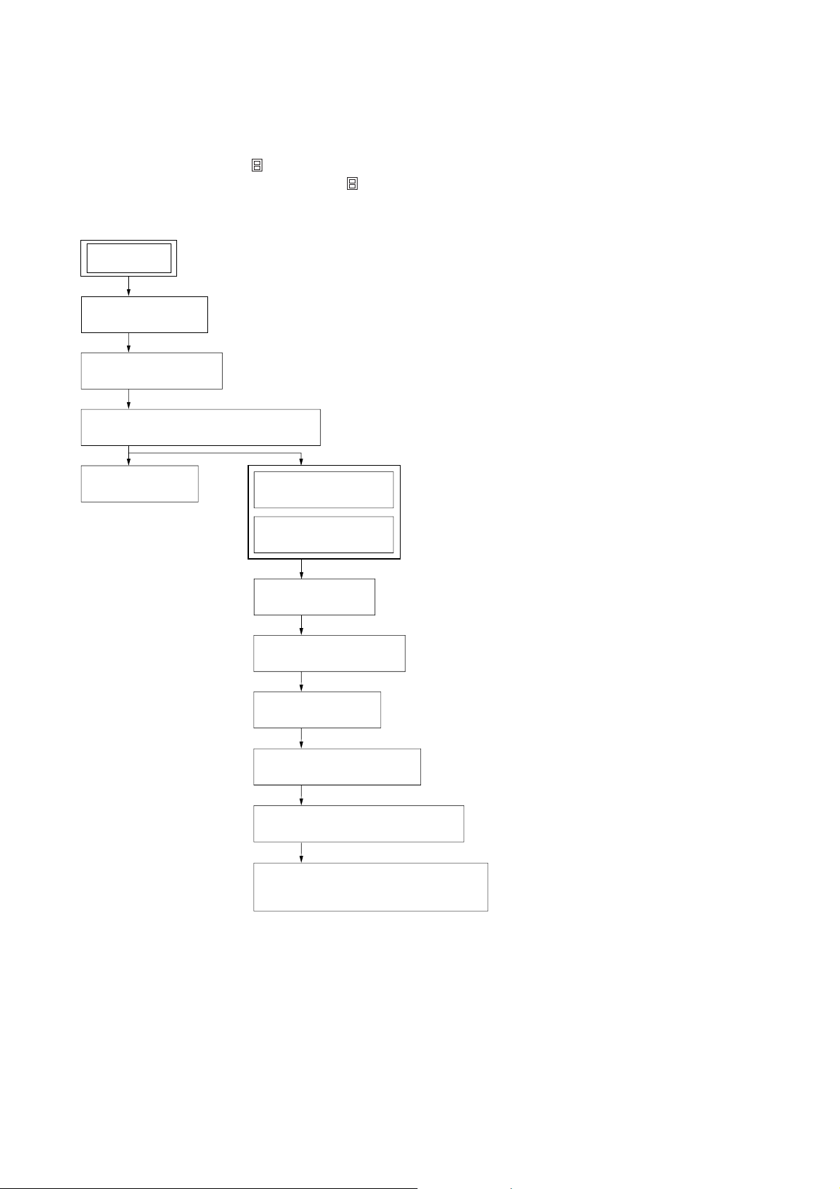
• This set can be disassembled in the order shown below.
3-1. DISASSEMBLY FLOW
Note 1: The process described in can be performed in any order.
Note 2: Without completing the process described in , the next process can not be performed.
Note 3: Illustration of disassembly is omitted.
SET
FRONT PANEL ASSY
(Note 3)
3-2. SUB PANEL ASSY
(Page 9)
3-3. MECHANISM DECK (MG-165A-138)
(Page 9)
3-4. MAIN BOARD
(Page 10)
3-5. SERVO BOARD
(Page 10)
3-6. MD COVER ASSY
(Page 11)
3-7. FLOAT BLOCK
(Page 11)
3-8. LEVER (LE23) ASSY
(Page 12)
3-9. HOLDER ASSY
(Page 12)
3-10. CHUCKING ARM ASSY
(Page 13)
3-11. OPTICAL PICK-UP (KMS-242E)
(Page 13)
3-12. SL MOTOR ASSY (SLED) (M902),
SP MOTOR ASSY (SPINDLE) (M901)
(Page 14)
8
Page 9
Note: Follow the disassembly procedure in the numerical order given.
r
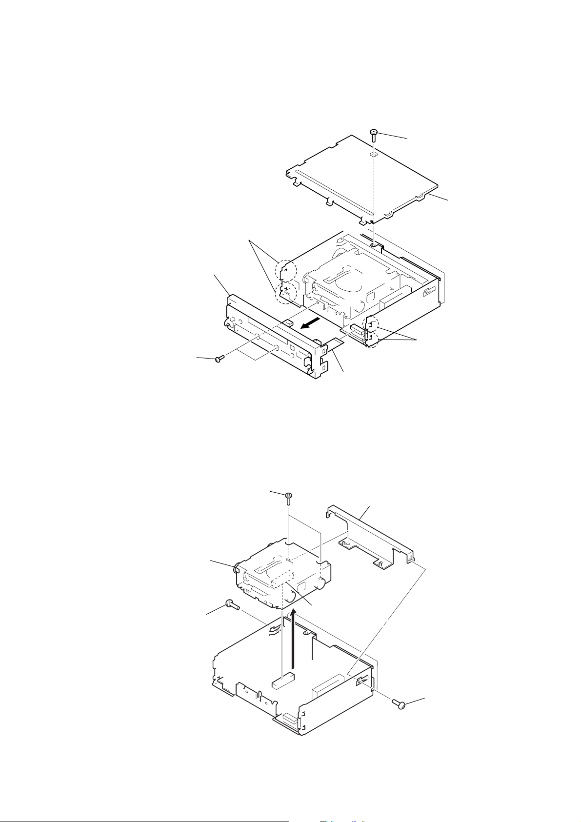
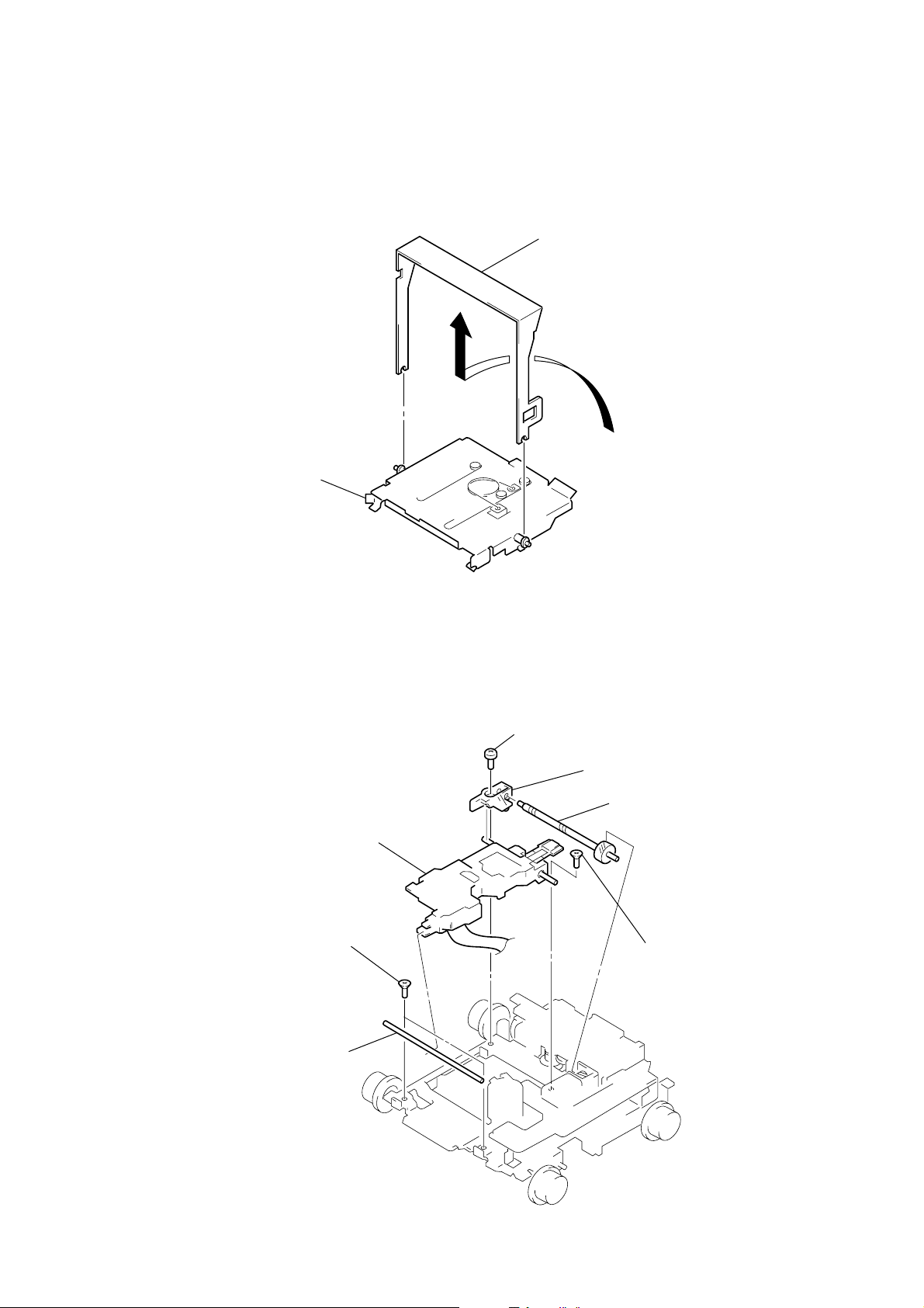
3-2. SUB PANEL ASSY
4
two claws
7
sub panel assy
1
screw
(PTT2.6 × 4)
MDX-CA790X
2
cove
3
two screws
(PTT2.6 × 6)
3-3. MECHANISM DECK (MG-165A-138)
3
two screws
(PTT2.6
5
mechanism deck (MG-165A-138)
1
screw
(PTT2.6
×
6)
5
4
two claws
6
flexible flat (14 core) cable
(CN370)
×
6)
4
bracket (MD)
2
connector
(CNP500)
1
screw
(PTT2.6
×
6)
9
Page 10
MDX-CA790X
e
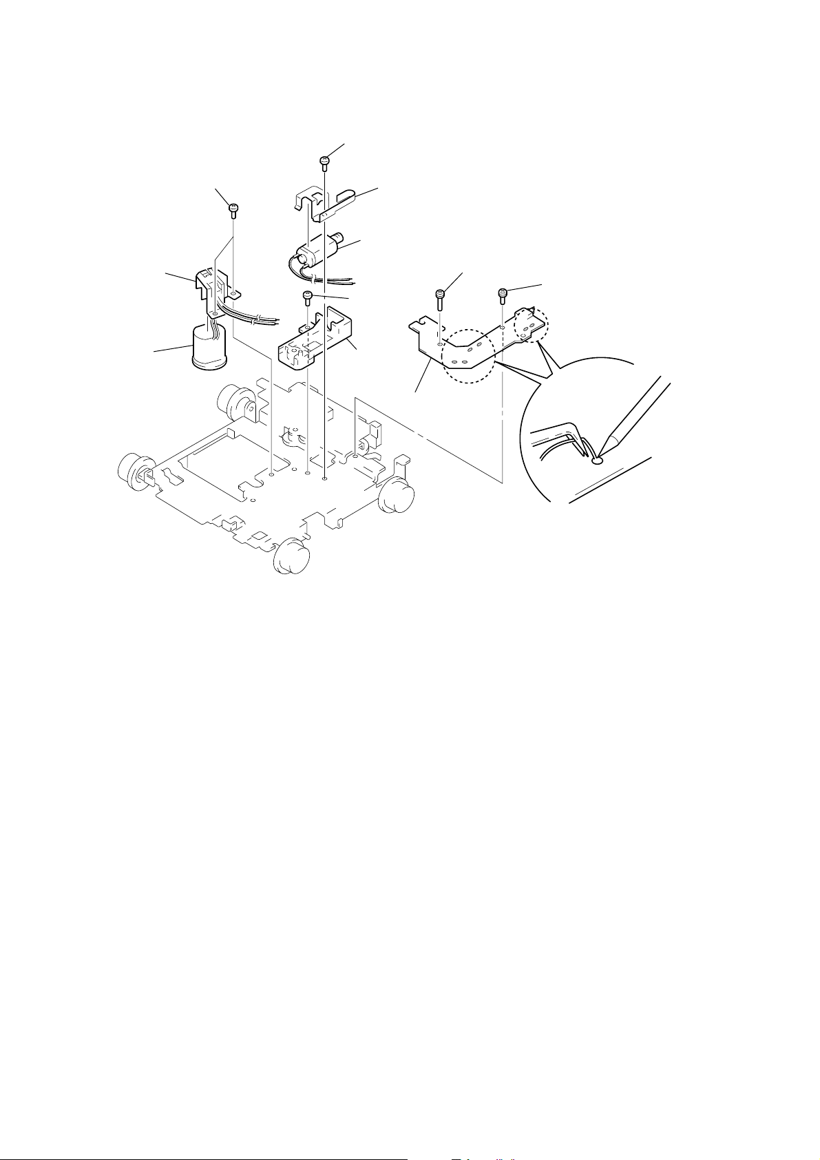
3-4. MAIN BOARD
1
three ground point
screws (PTT2.6
3
main board
×
6)
2
four screws
(PTT2.6
×
6)
3-5. SERVO BOARD
2
four screws
(BVTT2
3
1
×
4)
servo board
parallel (FFC) (10core) wir
(CN3)
10
1
optical pick-up flexible board
(CN2)
Page 11
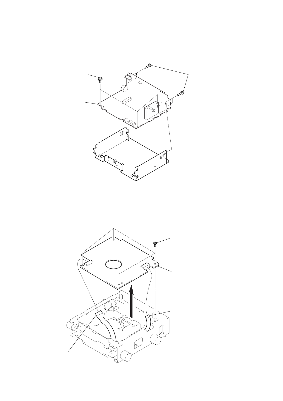
3-6. MD COVER ASSY
)
1
tension spring (FL2)
6
float block
1
tension spring (FL2)
2
two tension springs (float F)
3
Pushing an arrow A part, raise the float block
up ward at the front to release a lock.
A
4
float block
lever (lock R)
lever (lock L)
5
two dampers assy
5
two dampers assy
3
MD cover assy
shaft (MD cover guide)
cassette holder
1
four screws
(BVTT2 × 4
MDX-CA790X
3-7. FLOAT BLOCK
A
2
Pushing the cassette holder in the direction of the arrow A with a
screwdriver, etc., disengage the shaft (MD cover guide) from
the slot in the MD cover assy.
Note: Take care not to scratch the optiocal pick-up when pushing
the cassette holder with a screwdriver. etc.
11
Page 12
MDX-CA790X
y
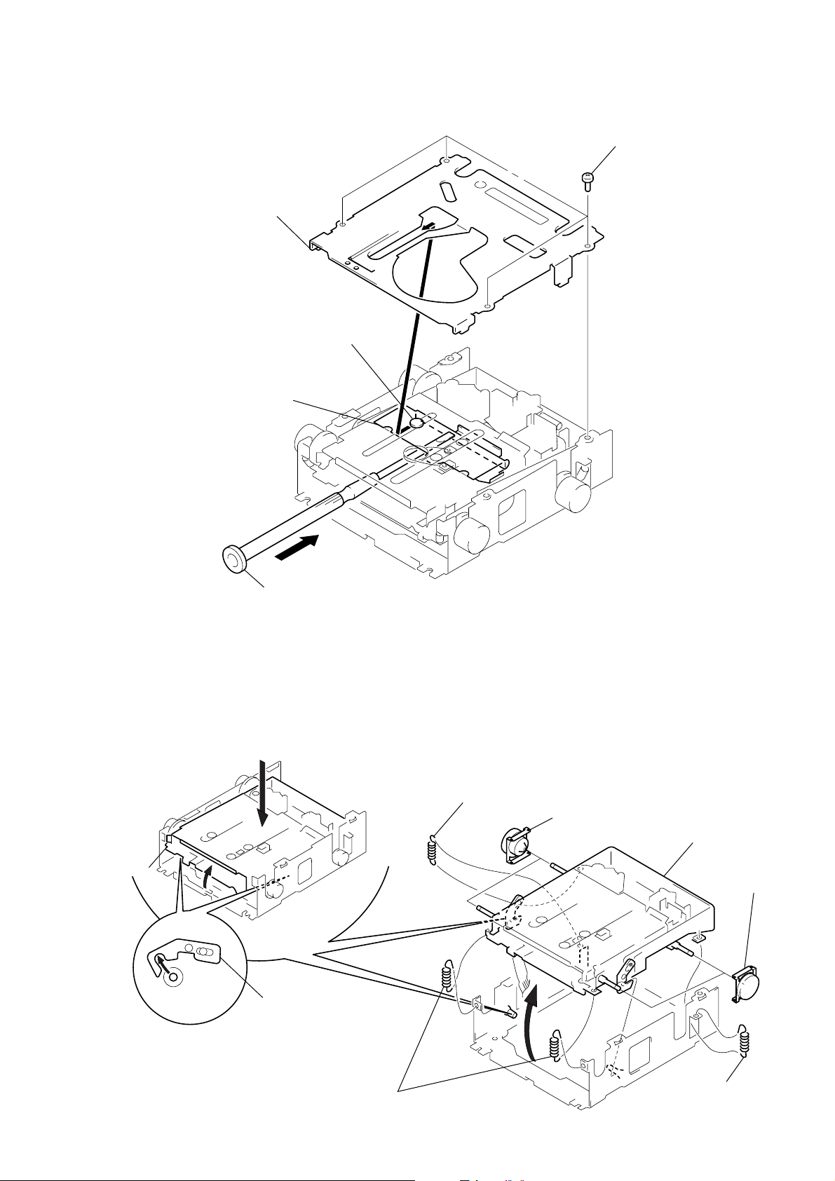
3-8. LEVER (LE23) ASSY
2
stopper washer
1
4
roller (GLE)
3
lever (LE23) ass
3-9. HOLDER ASSY
2
1
spring (CHKG)
2
type-E stop ring 1.5
3
lever (lock R)
type-E stop ring 1.5
4
Remove the holder assy in the
direction of the arrow.
2
type-E stop ring 1.5
12
3
lever (lock L)
2
type-E stop ring 1.5
1
spring (CHKG)
Page 13
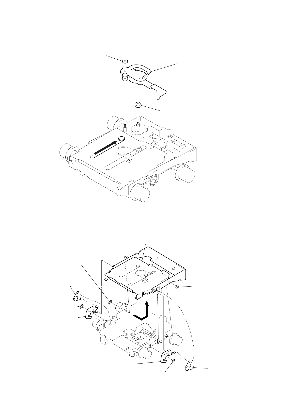
3-10. CHUCKING ARM ASSY
y
holder assy
1
Remove the chucking arm ass
in the direction of the arrow.
MDX-CA790X
3-11. OPTICAL PICK-UP (KMS-242E)
7
optical pick-up (KMS-242E)
1
two screws
(K2
×
3)
2
shaft (SL2)
4
screw
(B2
×
3)
6
bearing (SL)
5
feed screw assy
3
screw
(K2
×
3)
13
Page 14
MDX-CA790X
3-12. SL MOTOR ASSY (SLED) (M902), SP MOTOR ASSY (SPINDLE) (M901)
5
screw
×
1.8)
(P1.7
0
two screws
(P1.7
×
qa
retainer (SP)
qs
SP motor assy
(spindle) (M901)
1.8)
9
6
7
SL motor assy
(sled) (M902)
8
screw
×
(B2
base (SL)
bracket (SL)
3)
4
sensor board
3
screw (PS2 × 8)
2
screw (PS2 × 4)
1
Remove solders of motors
(M901, M902, M903).
14
Page 15

SECTION 4
ELECTRICAL ADJUSTMENTS
TEST MODE
This set have the test mode function.
<Set the Test Mode>
1. Turn ON the regulated power supply . (The clock is displayed)
Note: Press the [OFF] button, if the clock is not displayed.
2. Push the preset [4] button.
3. Push the preset [5] button.
4. Press the preset [1] button for more than two seconds.
5. Then the display indicates all lights, the test mode is set.
<Release the Test mode>
1. Push the [OFF] button.
MD SECTION
MD section adjustments are done automatically in this set.
TUNER SECTION
Tuner section adjustments are done automatically in this set.
MDX-CA790X
15
Page 16
MDX-CA790X
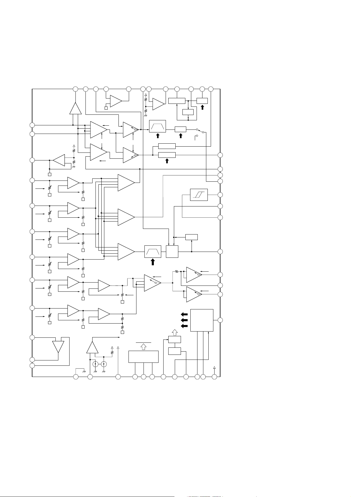
• IC Block Diagrams
– SERVO Board –
IC1 CXA2523AR
SECTION 5
DIAGRAMS
MORFO47MORFI46RFO45OPN
48
–
+
RFA1
+
–
AA
BB
CC
DD
EE
FF
–
–
–
–
–
–
–
GRVA
RFA2
1
2
OFST
1
2
EBAL
FBAL
HLPT
GRV
+
–
+
–
1I
2J
CVB
GSW
+
–
+
–
+
–
+
–
+
–
+
–
+
–
IV
3VC
4A
IVR
5B
IVR
6C
IVR
7D
IVR
8E
IVR
9F
IVR
OPO43ADDC42COMPP41COMPO40AGCI39RF AGC38RF37PEAK
44
USROP
EE'
–1
–2
–2
–1
–
–
–
–
+
+
–
–
–
–
+
+
ESW
FF'
–
+
–
+
BPF3T
BPF22
WBL
WBL
RFA3
PTGR
PBSW
ABCDA
FEA
ATA
EFB TESW
RF AGC EQ
+
–
USRC
3T
3T WBL
PEAK
BOTTOM
WBL
ADIP
AGC
PTGR
WBL
PEAK3T
P-P
PBH
3T
EQ
DET
–1
–2
–1
–2
DET
TEMP
EQ
AUX
SW
BPFC
SEA
TEA
VI CONV
TG
TG
36
BOTM
35
ABCD
34
FE
33
AUX
32 ADFG
31 ADAGC
30 ADIN
29 ADFM
28 SE
27 CSLED
26 TE
25 WBLADJ
16
15
AUXSW
TEMPR
COMMAND
SCRI - PARA
DECODE
17
16
SCLK
SWDT
BGR
VREF
24
23
22
21
20
19
18
XLAT
XSTBY
F0CNT
VREF
EQADJ
3TADJ
VCC
10PD
11APC
12APCREF
+
–
+
–
14
13
GND
TEMPI
Page 17
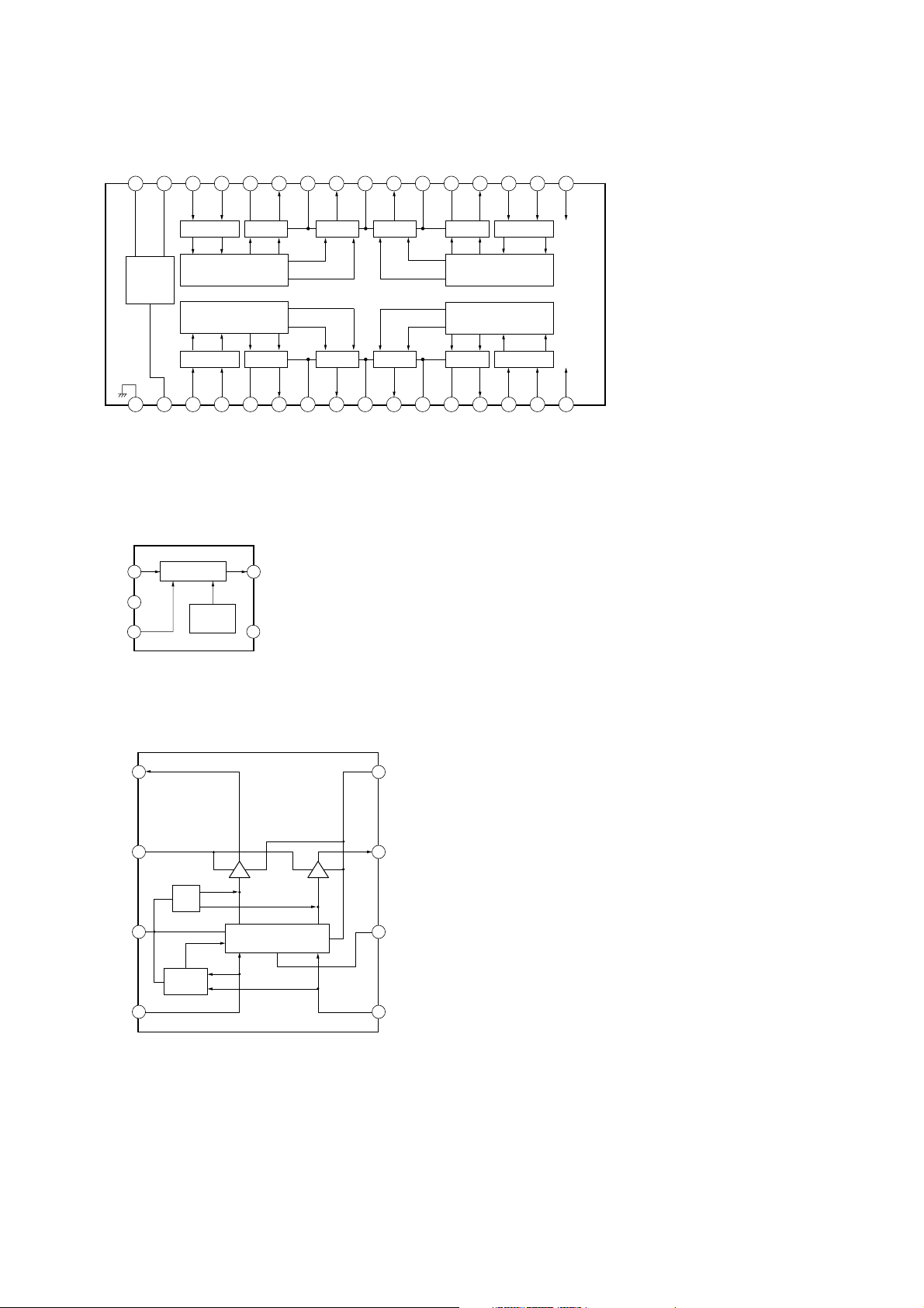
IC2 BH6519FS-E2
MDX-CA790X
CAPA–
CAPA+
IN2R
IN2F
VM2
OUT2F
PGND2
OUT2R
VM12
OUT1R
PGND1
OUT1F
VM1
32 31 30 29 28 27 26 25 24 23 22 21 20 19 18 17
IN4F
AMP
AMP
VM4
INTERFACE
CHARGE
PUMP.
OSC
INTERFACE
1 2 3 4 5 6 7 8 9 10 11 12 13 14 15 16
VG
GND
IN4R
OUT4F
AMP
PGND4
OUT4R
VM34
AMP
OUT3R
PGND3
AMP
AMPAMPAMP
OUT3F
INTERFACE
PREDRIVEPREDRIVE
PREDRIVEPREDRIVE
INTERFACE
VM3
IC3 R1114N251D-TR-FA
VDD
GND
REGULATOR
1
2
3
CE
CURRENT
LIMIT
VOUT
5
NC
4
IN1F
IN3F
IN1R
IN3R
V
PSB
DD
V
DD
PSB
IC6 BA6287F
1
OUT1
2
VM
TSD
3
VCC
POWER
SAVE
4
FIN
DRIVER DRIVER
CONTROL LOGIC
8
GND
7
OUT2
6
VREF
5
RIN
17
Page 18

MDX-CA790X
IC4 CXD2667R
FOK/FKS
120
TEST3
MTFLGR/TRK
118
119
FGIN
TEST1
117
TEST2
116
SPFD
115 114 113 112 111 110 109
SPRD
SFDR
SRDR
FS4
VSC3
108
VDC3
107
CLTV
106
FILO
105
FILI
104
PCO
103
AVS1
RFI
BIAS
AVD199ASYI98ASYO97DDOUT94DCHG
102
101
100
APC
DDIN
95
96
93
AUX292TE
SE
91
GFS/SLD
VDIO3
VSIO3
VDC0
MNT0
MNT1
MNT2
MNT3
SWDT
SCLK
XLAT
VSC0
SRDT
SENS
XRST
SQSY
TST2
DATAI
VDIOSC
OSCI
OSCO
VSIOSC
DAVSSL
VREFL
AOUTL
DAVDDL
DAVDDR
AOUTR
VREFR
DAVSSR
SWSW
TRK
SW
1
2
3
4
5
6
7
8
9
10
11
12
13
14
15
16
17
18
19
20
21
22
23
24
25
26
27
28
29
30
MONITOR
CPU I/F
OSC
LPF
CONTROL
SUBCODE
PROCESSOR
EACH
BLOCK
EACH
BLOCK
SW
D/A CONVERTER
DIGITAL
AUDIO
SPINDLE
SERVO
ADIP
DECODER
PWM
GENERATOR
ATRAC
ENCORDER/
DECODER
I/F
12
12
PLL
DIGITAL
SERVO
SIGNAL
PROCESSOR
AUTO
SEQUENCER
4Mbit
D-RAM
COMP
EFM/ACIRC DECODER
A/D
CONVERTER
RESISTANT
SHOCK
MEMORY
CONTROL
ANALOG
MUX
90
ADRB
AVS2
89
AVD2
88
87
ADRT
86
ADIO
85
VC
84
AUX1
83
FE
82
ABCD
81
BOTM
80
PEAK
79
VSC2
78
VDC2
77
TFDR
76
TRDR
75
LDDR
74
APCREF
73
DTRF
72
CKRF
71
XLRF
70
FOCNT
69
VSIO2
68
VDIO2
67
ADFG
66
MVCI
65
FRDR
64
FFDR
4
4
63
62
61
D3
D2
D0/FOK
18
31
32
VSC1
VDC1
33
MTFLGL
34
LRCK
XINT
36
DADT
37
3835
LRCK
39
XBCK
40
FS256
VDIO1
60
59
58
57
56
55
54
53
52
51
50
49
47
46
A03
45
A04
A1044A0043A0142A02
A05
A11
A0748A06
A08
VSIO1
XOE
XCAS
A09
XRAS
XWE
DVDD
DVSS
D1/GFS
41
Page 19

MDX-CA790X
– MAIN Board –
IC90 SAA6588T/V2-518
LVIN
20
MULTI
PATH
DETECTOR
2
1
MRO
MPTH
CIN
19
CLOCKED
COMPARATOR
RDS/RDBS
DEMODULATOR
TEST
CONTROL
3
TCON
SCOUT
18
BAND-PASS FILTER
OSCILLATOR
& CLOCK
4 5
OSCO
57kHz
8th ORDER
RDS/RDBS
DECODER
6
OSCI
VSSD
CLOCK
DATA
VDDD
VREF
17
87
DAVN
MPX
POWER SUPPLY
SIGNAL QUALITY
DECODER
445
INTERFACE
REGISTER
VSSA
15
& RESET
VDDA
14
CLOCK
DATA
IIC BUS SLAVE
TRANSCEIVER
9 10
1316
SDA
IC120 BD3802F-FE2
OUT-RROUT-
OUT-
VCC
FR
FADER
(0 to –58,
–∞ dB)
D-GND
SDA SCL MUTE SEL ADJ VCC
28 27 26 25 24 23 22 21 20 19 18 17
2
C BUS
I
LOGIC
VCO
FADER
(0 to –58,
–∞ dB)
ON OFF ON OFF
EFFECT (OFF,6dB,
10dB,14dB)
FL
FADER
(0 to –58,
–∞ dB)
EFFECT (OFF,6dB,
10dB,14dB)
AFIN
DETECTOR
SCL
PAUSE
OUT-
RL
FADER
(0 to –58,
–∞ dB)
MAD
PSWN
11
12
DS32 DS22 DS12
16 15
IC300 TDA8588AJ/N1 IC400 BA8271F-E2
TAB
1
VCC
BUS ON
LINK OFF
CLK OUT
11
5 6 7
4
GND
VREF
BUS CLK
OUT-FL-
OUT-FL+
OUT-RL-
OUT-RL+
IN-RL
S-GND
IN-RR
OUT-RR+
OUT-RR-
OUT-FR+
OUT-FR-
DIAG
ANT-REM
AMP-REM
SERVO3.3V
MECH6V
B.UP+B
VP
3
5
7
9
11
13
15
17
19
21
23
25
27
29
31
33
35
37
PROTECTION/
DIAGNOSTIC
CHIP DETECT/
DIAGNOSTIC
SWITCH
SWITCH
REFERENCE
DETECTION
VOLTAGE
FL
RL
RR
FR
BATTERY
MUTE
MUTE
STANDBY/
MUTE
TEMPERATURE
PROTECTION
LOADDUMP
PROTECTION
VP
ENABLE
LOGIC
REGULATOR
BACK-UP
SWITCHREGULATOR
I2C BUS
2
4
6
8
10
12
14
16
18
20
22
24
26
28
30
32
34
36
SDA
SCL
VP2
PGND3
SVR
IN-FL
IN-FR
BEEP
PGND2
VP1
STB
PGND1
RST
CRES
AUDIO8.3V
GND
PANEL+B
CBU
14 13 12
2 3
1
BUS ON IN
BUS ON OUT
DATA OUT
10
BUS DATA
DATA IN
RESET
89
RESET
SWITCH
BUS RESET
VCC/2
A-GND FIL BUS-
RCH
AN BUS-
LCH
TONE
PASS
BASS,TREBLE, MIDDLE
(–15dB to +15dB, 1dB STEP)
VOLUME
(+23 to –79dB, – ∞dB
1dB STEP)
INPUT GAIN
(0 to 15dB,1dB STEP)
MUTE MUTE
INPUT SELECTOR
(4 STEREO INCLUDE 1 ISOLATION INPUT)
6 7 8 9 10 11 123 4 521
TU-
TU-
RCH
LCH
CD-
RCH
TONE
PASS
BASS,TREBLE, MIDDLE
(–15dB to +15dB, 1dB STEP)
VOLUME
(+23 to –79dB, – ∞dB
1dB STEP)
INPUT GAIN
(0 to 15dB,1dB STEP)
CD-
LCH
D1 D2 DS1113DS2114DS31
1919
Page 20

MDX-CA790X
5-1. BLOCK DIAGRAM – SERVO Section –
OPTICAL PICK-UP BLOCK
(KMS-242E)
F
C B
I J
A
D
E
DETECTOR
LDPD
LASER DIODE
ILCC
MON
I
J
B
A
C
D
E
F
AUTOMATIC
POWER CONTROL
Q1
MD DSP
IC4 (1/2)
DADT
36
XBCK
38
LRCK
FILI
105
PCO
104
CLTV
107
FILTER
48 47
MORFI
MORFO
I
1
J
2
A
4
B
5
I-V
C
AMP
6
D
7
E
8
I-V
F
AMP
9
APC
11
PD
10
RF AMP
LD/PD
AMP
RFO
46 40
B.P.F.
3T
TEMP
WBL
AT
B.P.F.
AMP
ABCD
AMP
COMMAND
SERIAL/PARALLEL
CONVERTER,
DECODER
APCREF
12
SWDT
ADFM
SCLK
FOCUS
ERROR AMP
TRACKING
ERROR AMP
XLAT
181716
RF AMP,
FOCUS/TRACKING ERROR AMP
AGCI
WBL
PEAK &
BOTTOM
ADIN
3029
EQ
V-I
CONVERTER
IC1
RF AGC
& EQ
EQ
3T
WBL
RF
AUX AUX
PEAK
BOTM
ADFG
ABCD
FE
TE
SE
F0CNT
38
33
PEAK
37
BOTM
36
32
ABCD
35
FE
34
TE
26
SE
28
20
SERVO
3.3V
106
98
99
102
67
70
FILO
ASYO
ASYI
RFI
ADFG
F0CNT
COMPA-
RATOR
DECODER
ADIP
PLL
SPINDLE
SERVO
SPFD
SPRD
114 113
SPFD
SPRD
EFM/ACIRC DECODER
SUBCODE
PROCESSOR
SQSY35XINT
16
ATRAC
SHOCK RESISTANT
MEMORY CONTROLLER
INTERFACE
XRST
SENS13SRDT
15 14 9 10 11
SENS
SRDT
ENCODER/DECODER
XWE
XRAS
XCAS
CPU
SWDT
SCLK
XLAT
SWDT
SCLK
XLAT
4Mbit
D-RAM
D/A
CONVERTER
MONITOR
CONTROL
MNT0
MNT1
MNT2
5 6 7 8
LPF
OSC
MNT3
37
FS256
39
AOUTL L-CH
25
AOUTR
28
OSCI
20
OSCO
21
D0 – D3A00 – A11
60 – 63
41 – 51, 55
XOE
53
XWE
57
XRAS
56
XCAS
54
• R-ch is omitted due to same as L-ch.
• SIGNAL PATH
: MD PLAY
R-CH
X1
22.57MHz
A
(PAGE 21)
2-AXIS
DEVICE
(TRACKING)
FCS+
(FOCUS)
FCS–
TRK+
TRK–
FOCUS/TRACKING COIL DRIVE,
SPINDLE/SLED MOTOR DRIVE
M901
(SPINDLE)
M902
(SLED)
IC2
MM
M
DTRF
CKRF
XLRF
SRDT
SENS
SRDT
SWDT
SWDT
(LIMIT)
SCLK
SCLK
MD-LAT
LIMIT_IN
LO_6V
MNT2
LOAD_END
CHUCKING
DETECT
ON : When completion
of a disc loading
SENS
FE
TE
SE
AUX
PEAK
ABCD
16
PSB
OUT4F
6
OUT4R
8
OUT2F
27
OUT2R
25
OUT1F
21
23
OUT1R
OUT3F
12
10
OUT3R
IN4R
IN4F
IN2F
IN2R
IN1F
IN1R
IN3F
IN3R
SPFD
3
SPRD
4
SFDR
29
30
19
18
14
15
112
SRDR
111
FFDR
64
FRDR
65
TFDR
77
TRDR
76
MD DSP
IC4 (2/2)
74 83 92 91 80 81 84 82
FE
APCREF
DIGITAL SERVO
SIGNAL
PROCESS
PWM GENERATOR
BOTM
TE
SE
PEAK
BOTM
ANALOG MUX
A/D CONVERTER
FROM CPU
INTERFACE
AUTO
SEQUENCER
AUX
ABCD
PEAK HOLD
XLRF
CKRF
DTRF
FOK/FCS
Q2
XLRF
71
CKRF
72
DTRF
73
120
REF_
41
LEVEL
FOK
100 85
84
5 4
LOADING
MOTOR DRIVE
1 7
M903
(LOADING)
52 46 1695 18
SQ_SY
CC-XINT
MD MECHANISM CONTROLLER
EJECT
LOAD
FIN
RIN
IC6
6
VREF
OUT1
OUT2
M
MD-RST
IC7 (1/2)
REFERENCE VOLTAGE
REGULATOR
Q3
XLAT
X2
18.43MHz
8194
X1
8019 9817
X0
ATT
DISC-IN
538887
LOADING
DETECT
ON : When a disc loading start
and a disc eject completion
7
MECH_ATT
B
(PAGE 21)
2020
Page 21

5-2. BLOCK DIAGRAM – MAIN Section –
MDX-CA790X
(PAGE 20)
L-CH
A
FM/AM
ANTENNA IN
J10
ANT
PJ210 (1/2)
BUS
AUDIO IN
15
10 11
E2PVDD
VCC8.3V
FM/AM
TUNER PACK
TU10
VDD5V
SDA
SCL
L
R
L
R
BU5.0V
AU 8.3V
TU5V
41
14
11313
119RDS_OUT
115QUALITY
R-CH
R-CH
I2C_SDA
I2C_SCL
RDS DECODER
16 MPX 19 CIN
OSCI
OSCO
5 4
X90
4.332MHz
AP2
5
D2
11
B2
7
IC90
1118SCOUT 119SDA
DAVN
8
INPUT
SELECTOR
1110SCL
INPUT SELECT,
ELECTRICAL VOLUME
MUTE
R-CH
INPUT
GAIN
MUTE VOLUME
I2C_SDA
I2C_SCL
IC120
IIC BUS
LOGIC
SDA
27
I2C_SDA
SCL
2625
I2C_SCL
TONE CONTROL/
EFFECT
CIRCUIT
OUT-FR
OUT-RR
21
20
FADER
FADER
• R-ch is omitted due to same as L-ch.
• SIGNAL PATH
: MD PLAY
: FM
: AM
: BUS AUDIO IN
R-CH
R-CH
MUTING
CONTROL
Q350, 351
MUTING
Q210
MUTING
Q240
MUTING
Q220
MUTING
Q230
12
14
11
15
POWER AMP
IC300 (1/2)
IN-FL
IN-FR
IN-RL
IN-RR
PJ210 (2/2)
OUT-FL+
OUT-FL–
OUT-FR+
OUT-FR–
OUT-RL+
OUT-RL–
OUT-RR+
OUT-RR–
L
AUDIO OUT
FRONT
R
L
AUDIO OUT
REAR
R
CN300 (1/2)
5
3
21
23
9
7
17
19
1
9
4
12
2
10
3
11
FRONT L+
FRONT L–
FRONT R+
FRONT R–
REAR L+
REAR L–
REAR R+
REAR R–
E2PSDA
17 16
68
E2P_SIO
E2PSCL
67
E2P_CKO
TUN_MUTE
MUTE_CON
7 8
64
28
TUATT
TUATTIN
6
93
VSM S-METER
92
QUALITY
Q71
NOISE DET
DISCHARGE
SWITCH
66
NS_MASK
82
DAVN
SYSTEM CONTROLLER
IC600 (1/2)
I2C_SDA
57 79 81
VOLATT
I2C_SIO
I2C_SCL
I2C_CKO
BEEP
AMPSTB
DIAG
ATT
I2C_SDA
I2C_SCL
85
70
56
24
D350
2
SDA
4
SCL
16
BEEP
22
STB
25
DIAG
MECH_ATT
B
(PAGE 20)
2121
Page 22

MDX-CA790X
5-3. BLOCK DIAGRAM – PANEL/BUS CONTROL/POWER SUPPLY Section –
CNJ400
BUS CONTROL IN
RESET
DATA
CLK
BUS ON
BATT
SONY BUS INTERFACE
IC400
2
5
4
6
TH400
7
BUS ON SWITCH
BAT B+
Q401, 405
D404
RST
DATA I/O
CLK
BUS
ON
RESET
SWITCH
BUS ON
SWITCH
2 13
6 9
4 11
1 12
RST
DATA IN
DATA OUT
CLK-IN
BUS ON
MD MECHANISM CONTROLLER
UNISO
UNISI
UNICLK
BUS_ON
EJECT_OK
LINKOFF
UNISO
UNISI
UNICKO
BUSON
DOORSW
IC7 (2/2)
MDMON
1 15
30 39
MDMON
RSTX
OPEN_REQ
OPENREQ
S601
RESET
D500
LO_6V
SERVO3.3V
RESET SIGNAL
GENERATOR
IC601
BU3.3V
D700
+3.6V
REGULATOR
IC700
BU5.0V
D701
REGULATOR
IC300 (2/2)
27 ANT-REM
29 AMP-REM
37 REG2
CN300 (2/2)
5
6
AMP-R
ANT-R
69MDMON_CHECK
70MDON_CHECK
51BU_IN
93MD_ON
75
42SYSRST
19RESET
D405
UNISO
UNISI
8
UNICKO
BUS-ON
CN901
FRONT PANEL
SIDE
1
CN370
MAIN UNIT SIDE
5
UNISO
UNISI
UNICKO
BUS-ON
UNISO
UNISI
UNICKO
BUS-ON
(1/2)
D405
57
56
58
50
14
2
(2/2)
33
34
35
40
55
J370
(REMOTE IN)
LSW901, 904 – 910,
LSW912 – 922,
S902, 903, 911
96 20 95
RCIN0
RCIN1
LSW801,
KEYIN0
94
KEYIN1
D600
78
DI
77
IC901
IC971
83
IC600 (2/2)
SIRCS
OSC
CL
76
CE
74
OSC
C985, R989
X601
27.648MHz
OSCOUT
LIQUID CRYSTAL
DISPLAY
LCD901
KEY ACTIVE
SWITCH
Q600
27 25 12 13
ADON
KEYACK
BU3.3V
LCD DRIVER
65 – 68 1 – 64
COM1 – COM4 SEG1 – SEG64
REMOTE CONTROL
RECEIVER
SYSTEM CONTROLLER
(NOSE DETECT)
16 15
OSCIN
S600
X602
32.768kHz
XOUT
XIN
59
76
78
77
NOSESW
LCDSO
LCDCKO
LCDCE
DOORIND
+5V
DRIVER5V
29MDON
69
31BUIN
21ACCIN
23TELATT
22TESTIN
REGULATOR
CONTROL
Q505
(DISC SLOL ILLUMINATION)
LO_6V
L2.5V
SERVO3.3V
TU5V
LED903, 911, 933, 934,
LED951 – 954,
LSW901, 904 – 910,
LSW912 – 922
LED801
LSW801
Z
REGULATOR
REGULATOR
REGULATOR
AU8.3V
ILL 10V
LED801,
LSW801
BATTERY DETECT
Q404
Q504
+2.5V
IC3
+5V
Q60
ACCESSORY
CHECK
Q361
LEVEL SHIFT
Q360
LED DRIVE
Q370
VOLTAGE
CHECK
Q402, 403
33 REG4
31 REG3
30 REG1
34 REG5
D406
D407
35VP
BAT B+
19
+B
7
ACC
13
TEL-ATT
15
TEST
2222
Page 23

MDX-CA790X
5-4. NOTE FOR PRINTED WIRING BOARDS AND SCHEMATIC DIAGRAMS
Note on Printed Wiring Board:
• X : parts extracted from the component side.
• Y : parts extracted from the conductor side.
• : Pattern from the side which enables seeing.
(The other layers' patterns are not indicated.)
Caution:
Pattern face side: Parts on the pattern face side seen from
(Side B) the pattern face are indicated.
Parts face side: Parts on the parts face side seen from
(Side A) the parts face are indicated.
Note on Schematic Diagram:
• All capacitors are in µF unless otherwise noted. pF: µµF
50 WV or less are not indicated except for electrolytics
and tantalums.
• All resistors are in Ω and 1/
specified.
f
•
• C : panel designation.
Note: The components identified by mark 0 or dotted line
• A : B+ Line.
•Power voltage is dc 14.4V and fed with regulated dc power
•Voltages and waveforms are dc with respect to ground
•Voltages are taken with a V OM (Input impedance 10 MΩ).
•Waveforms are taken with a oscilloscope.
• Circled numbers refer to waveforms.
• Signal path.
: internal component.
with mark 0 are critical for safety.
Replace only with part number specified.
supply from ACC and BATT cords.
under no-signal (detuned) conditions.
– SERVO Section –
no mark : MD PLAY
– MAIN/KEY Section –
no mark : FM
〈〈 〉〉 : MW
[]: LW
(): MD PLAY
Voltage variations may be noted due to normal production tolerances.
Voltage variations may be noted due to normal production tolerances.
E : MD PLAY
F : FM
f : AM (MW/LW)
L : BUS AUDIO IN
4
W or less unless otherwise
• Circuit Boards Location
MAIN board
KEY board
MINI JACK board
SENSOR board
SERVO board
SUB board
2323
Page 24

MDX-CA790X
5-5. SCHEMATIC DIAGRAM – SERVO Section (1/2) – • See page 31 for Waveforms. • See page 16 for IC Block Diagrams.
M901
(SPINDLE)
M902
(SLED)
M903
(LOADING)
(CHASSIS)
TP16
(SP-BLK)
TP17
(SP+RED)
(SL+RED)
TP18
(SL-BLK)
TP19
TP20
(LO+RED)
TP21
(LO-BLK)
(LOADING DETECT)
(CHUCKING DETECT)
(LIMIT)
(1/2)
R
R
D
D
F
+
ADAGC
CSLED
WBLADJ
BOTM
ADFM
S
C
F
1
PGND
3
ND
PG
+
K
R
T
(PEAK)
ABCD
ADFG
ADIN
R
F
F
C35
100
D
C
6.3V
B
A
T
C
N
C33
0.1
1
D
1R
T1F
OU
OUT3F
TP32
(RF)
TP27
FE
AUX
SE
TE
D
V
IN1F
VM
IN
3
3R
PSB
IN
IN3F
VM
C29
0.1
R
R
D
R
FD
T
T
TP25
(BTM)
TP26
(ABCD)
TP35
(FE)
BP3
A7
C18
1
C19
0.0047
TP34
(SE)
A6
BP2
C20
0.068
A5
BP1
TP33
(TE)
R13
56k
C11
0.1
FFDR
FRDR
A7
C26C25
A4
A3
A2
A1
R14
TRDR
TFDR
C32
A8
0.010.01
R16R15
2.2k
2.2k2.2k
0.1
C27
0.1
D3
FFDR
FRDR
MVCI
ADFG
VDIO2
VSIO2
F0CNT
XLRF
CKRF
DTRF
APCREF
LDDR
TRDR
TFDR
VDC2
VSC2
PEAK
BOTM
ABCD
FE
AUX1
VC
ADIO
ADRT
AVD2
6
A
C31
0.1
C34
0.1
D
A09
XWE
XCAS
XRAS
DVD
1/GFS
D
D0/FOK
D2
AVS2
ADRB
E
TE
S
UT
G
2
IN
C
DO
AUX
DCH
D
DD
AP
R17
10k
C36
0.01
R18
C38
100k
0.1
C47
C37
22 10V
5
A
0.47
OU
V
D
+2.5V REGULATOR
CE
A05
MD DSP
CXD2667R
CO
P
IC3
R114N251B-TR
C45
0.1
C40
1
A03
A02
A01
A00
A10
A04
IC4
I
FILO
FIL
R24C42
1k0.47
C43
0.015
R23
150
VDIO1
TEST3
VDC3
FS4
SRDR
VSC3
CLTV
C44
0.1
R
R
D
D
F
R
S
S
GND
VD
A06
A07
A08
A11
XOE
VSIO1
DVSS
1
I
SY
A
ASYO
VS1
AVD
A
BIAS
RFI
R21
680k
3.3k
R19
R20
1k
C39
R22
100p
1M
9
A
FS256
L
TFLG
M
MTFLGR/TRK
SFDR
D
R
P
S
T
IN
X
C58
C51 C48
0.01 0.1
XINT
LRCK
XBCK
DADT
DOUT
DAVDDR
VREFR
AOUTR
GFS/SLD
VSIO3
VDIO3
FGIN
TEST1
TEST2
DAVDDL
AOUTL
VREFL
DAVSSL
VSIOSC
VDIOSC
DATAI
SWDT
MNT3
MNT2
MNT1
MNT0
C52
0.1
OSCO
OSCI
XTSL
SQSY
XRST
SENS
SRDT
VSC0
XLAT
SCLK
VDC0
C1
C1
VS
VD
DAVSSR
FOK
SPRD
SPFD
D
F
P
S
47
4V
C46
0.1
C50
2.2
C49
2.2
R29
47
C55
TP72 TP68
(M3) (M2)
TP71
(M1)
TP67
(M0)
10µH
100p
L2
22.57MHz
L3
10µH
R38
0
L4
10µH
C57
0.1
X1
R30
R28
C59
47
4V
R40
1k
R39
1k
SQSY
0.01
10k
10k
C53
SRDT
C56
100p
XLAT
SCLK
SWDT
C54
100p
S
C
-
+
D
E
L
S
+
L
D
P
S
P
PM
CO
XSTBY
0.0022
4.7k
R10
F
D
E
L
S
2
12
T2R
UT2F
O
UT4F
O
UT1R
VM
O
OU
PGND
34
T4R
ND4
UT3R
VM
O
OU
PG
L
D
P
-
S
K
R
T
C17
9
8
A
A
0.0047
C21
CI
RF
PO
M
AG
PEAK
RFAGC
CO
DJ
F0CNT
EQA
VCC
VREF
3TADJ
13k
13k
33k
R11
R12
R9
R
R
D
D
F
R
S
S
C22
0.01
CN3
10P
SP-
SP+
SL+
SL-
LO+
LO-
C-SW
GND
E-SW
IN-LIMIT
CN2
20P
VCC
J
B
A
VC
I
F
C
D
E
VEE
ILCC
LDG
VR
MON
NC
FCS-
FCS+
TRK-
TRK+
J
B
A
F
ILCC
MON
FCS-
FCS+
TRK-
TRK+
I
J
AI
B
F
ILCC
MON
TP22
(IOP)
R2 R3
10 10
DISC_IN
LOAD_END
C8
0.1
C6
22
10V
Q1
MSB709-RT1
AUTOMATIC
POWER
CONTROL
TP5
(PD)
SPDL+
SLED+
0.001
SPDL-
SLED-
SPINDLE/SLED
MOTOR RIVE,
LO+
LO-
LIMIT
TP13
TP14
TP9
TP12
TP8
TP11
TP7
TP10
R5
47
R4
100
C4
R1
4.7k
C5
0.0068
R6
470k
FOCUS/TRACKING
COIL DRIVE
IC2
BH6519FS-E
C13
0.1
FI
RFO
OR
O
(I)
(J)
(A)
(B)
(C)
(D)
(E)
(F)
R7
470k
0.022
C12
1
A
I
J
VC
A
B
C
D
E
F
PD
APC
APCREF
M
M
PI
TEM
GND
IN2F
IN2R
CAPA-
CAPA+
IN4F
IN4R
GND
VG
C23
0.1
D
D
R
F
P
P
S
S
C15
0.01
C16
0.022
FO
PO
R
O
OPN
ADDC
RF AMP,FOCUS/TRACKING
ERROR AMP
IC1
CXA2523AR
PR
DT
TEM
XLAT
SW
SCLK
4
3
2
A
A
A
2
VM
4
VM
Z1
Z2
Z3
Z4
Z5
Z6
Z7
Z8
Z9
Z10
Z11
Z13
Z14
Z15
Z16
Z17
(Page 25)
2424
Page 25

5-6. SCHEMATIC DIAGRAM – SERVO Section (2/2) – • See page 31 for Waveform. • See page 16 for IC Block Diagram.
(2/2)
Z1
Z2
Z3
Z4
Z5
Z6
Z7
Z8
Z9
Z10
R50
(Page 24)
1k
LOADING MOTOR DRIVE
Q3
MSD601-RT1
OUT1
GND
VM
OUT2
VCC
VREF
FIN
TP77TP78
R43 R47
(LO+)(LO-)
100 100
-
+
O
O
L
Z11
Z13
Z14
Z15
L
IC6
BA6287F-T1
D
A
O
L
RIN
C63
0.1
T
C
E
J
E
REFERENCE
VOLTAGE
REGULATOR
MM3Z5V6ST1
D1
MD_ON
DISC_IN
LOAD_END
LIMIT
18.43MHz
EJECT
LOAD
LIMIT
LOAD_END
47k
R62
47k
R61
47k
R60
C62
0.1
X2
R44
0
C80C81
0.10.1
100
R42
100
R36
R32
100
R31
100
R45
100
NC
XOA
VSS
X0
X1
VCC
NC
EJECT
LOAD
NC
LIMIT_IN
LOAD_END
INIT1
INIT2
INIT3
NC
MD_ON
MD_RST
SENS
NC
NC
MNT2
NC
FOK
X
T
S
R
C64
0.01
C
TX
N
S
R
F
N
F
O
M
KO
D
M
LIN
R92
33k
R94 R91
100k 30k
C
C
C
CK
CK
N
N
N
E
E
H
_C
_CH
N
N
O
O
D
D
M
M
M
M
-PW
W
TT
R
C
C
R
TP
E
N
N
3
A-A
C
C
C
C
N
N
N
N
MD MECHANISM CONTROLLER
MB90473PFV-G-150
O
A_
PH
S
C
C
M
N
N
E
VS
C
N
-BNDE1
C
N
C
C
N
N
IC7
T
K
IS
_O
_EX
T
ISC
JEC
D
E
MDX-CA790X
CN5
DISC_EXIST
MD_ON
EJECT-OK
I
K
O
L
IS
IN
IS
N
IC
N
U
N
U
U
C
C
N
Q
E
_R
EN
P
O
O
M
LK
N
IS
W
IC
N
-P
N
U
R
U
E
D
A
T
T
T
K
-LA
D
D
D
CL
M
SW
SR
S
Y
_
S
C
-IN
Q
IS
S
U
D
B
C83
0.1
R63R58 C78
100100 0.01
I
C
IS
N
N
U
C
C
C
N
V
R66
100
100
R37
BU_IN
C
SY
N
-IN
_
C
IS
SQ
D
BUS_ON
MD2XIA
MD1
MD0
CC-XINT
NC
NC
NC
NC
REF_LEVEL
VSS
NC
NC
NC
NC
AVSS
AVRH
AVCC
NC
NC
NC
NC
NC
FLASH_W
TXD
D
C
X
C
C
N
R
N
N
C70
47
N
4V
O
-
R67
100
R68
100
C71R76
R70
100k
R69
100k
1470k
Q2
MSD601-RT1
PEAK
HOLD
C69
0.1
TXD
R77
680
S
U
B
T
IN
X
D
C
B
A
L5
0
MDMON
OPEN_REQ
LINKOFF
BUS-ON
A-ATT
BU-IN
UNISI
UNISO
UNICLK
TXD
RXD
RSTX
BP5
BP6
DISC_EXIST
MD-ON
EJECT_OK
MECHA-ON
OPEN_REQ
LINK_OFF
BUS_ON
A-ATT
B/U_CHECK
A-GND
UNISI
A3.3V
UNISO
DGND
UNICK
D3.3V
TXD
NC
LCH
FLASH-W
AUDIO_GND
RXD
RCH
LO_6V
SYS_RST
DRIVER_5V
B/U_3V
DRIVER_GND
B/U_GND
DRIVER_GND
30P
(Page 29)
100
100
100
100
100
R53
R54
T
Q
K
E
F
N
F
O
O
K
M
D
IN
L
Z16
Z17
M
T
T
-A
A
IS
R
X
-O
_
E
T
N
_
C
E
C
E
P
J
IS
E
O
D
100
R35
R56
R57
R59
C68
0.1
T
T
K
T
D
D
L
A
L
C
W
R
X
S
S
S
R25
100k
R65
100
D
X
R
2525
Page 26

MDX-CA790X
5-7. PRINTED WIRING BOARDS – SERVO Section – • See page 23 for Circuit Boards Location.
• Semiconductor
Location
Ref. No. Location
D1 C-3
IC1 G-5
IC2 E-3
IC3 E-6
IC4 F-7
IC6 B-3
IC7 C-4
Q1 F-15
Q2 D-4
Q3 C-2
1 2 3 4 5 6 7 8 9 10 11 12 13 14 15 16
MAIN BOARD
A
C42
(Page 27)
CN3
C59
C46C45
R22
CNP500
L2
30
C47
C50
C51
1
C48
C57
R40
X1
R29
C53
C55
C54
C49
R39
C56
1-687-046-12(12)
A
SERVO BOARD
B
C
D
E
F
G
OPTICAL PICK-UP
BLOCK
KMS-242E
H
R43
(SIDE A)
IC6
R50
BP6
BP5
C63
D1
Q3
C35
R45
R47
C33
1
C68
25
26
R25
R70
R65
R69
C29
R44
IC7
R77
C69
C71
Q2
IC2
C23
C22
CN2
C8
C6
C5
R6
R1
C17
C15
C13
48
1
IC1
R7
C12
12
13 24
C81
C80
X2
76100
50
C78
R68
R76
C70
L5
R61R62
C83
R60
75
51
R66
R67
R91
R94
R58
R63
R92
R37
L3
135
IC3
CN5
C58
4
C34
60 31
61
IC4
C16
C11
C21
37
36
BP3
25
R12
R11
R9
R10
C19
R13
90
91 120
R17
R18
C27
BP2
BP1
R24
R21
C36
R20
C37
SERVO BOARD
(SIDE B)
R38
R30
R28
C64
C62
R42
R36
L4
C40
C31
C44
C52
R23
C43
R16
C26
R19
C39 C38
C32
R14
R15
C25
C18
C20
R53
R32
R31
R54
R35
R59
57
R
R56
Q1
R3
R2
R5 R4
C4
1-687-046-12(12)
17
M901
RED
M
M902
(SLED)
(SPINDLE)
BLK
BLK
1-687-047-
M
RED
12
(12)
(SIDE B)
(LOADING DETECT)
1-687-047-12(12)
(LIMIT)
SENSOR BOARD
I
SENSOR BOARD
(SIDE A)
CHUCKING
DETECT
RED
BLK
J
K
M
M903
(LOADING)
L
2626
Page 27

5-8. PRINTED WIRING BOARDS – MAIN Section – • See page 23 for Circuit Boards Location.
MDX-CA790X
A
B
C
D
E
F
G
H
I
J
K
L
M
1 2 3 4 5 6 7 8 9 10 11 12 13 14 15 16
JW088
JW101
JW008
Q405
R303
JW007
Q505
R407
JW111
R502
Q360
R408
JW102
(NOSE DETECT)
(FRONT VIEW)
C331
D312
C330
R406
R405
JC504
Q402
Q403
Q404
R360
R614
JW097
R615
104
JW
JW103
C601
C402
JW110
S600
R613
R365
78
JW105
456
123
CNJ400
TH400
JW091
JW092
JW093
IC400
R364
Q361
D406
D407
JW089
JW096
JW106
CNJ400
BUS CONTROL
IN
123
78
456
C400
D375
D403
D401
D402
JW109
CN371
JW001
JW002
L300
JW003
C401
JW004
JW005
JW090
JC404
JW094
R403
R411
C602
1-687-861-11(11)
Q401
JW107
R412
R404
J370
REMOTE IN
R375
RL+ RL–
GRN
ANT REM
FL+ FL–
WHT
FR+ FR–
GRY
RR+ RR–
VIO
WHT
1 9
GRN
2 10
VIO
3 11
GRY
4 12
5 13
BLU
6 14
RED
7 15
BLK
8 16
ACC GND
RED
BLU
NC BATT
NC NC
TO
CN300
MAIN BOARD
(CHASSIS)
JW043
C12
C13
C16
JW044
R10
C380
JC380
JW145
J10
(FM/AM ANTENNA IN)
TU10
(FM/AM TUNER PACK)
JC80
C17
C18
R12
R13
R19
R14
R15
C11
R94
C99
C98
C97
C96
R372
R373
R374
JW144
R16R17
BUS AUDIO
IN
L R
C211
JW035
JW150
Q71
JW041
D72
R79
C10
C15
C14
D60
R92
C100
R95
IC90
R377
R378
R371
14
13 1
C60
C61
D373
X90
R221
R211
R18
R20
R96
C93
JW143
JW034
JW045
Q60
CN370
C221
C804
R220
R91
R210
C210
JW046
C94
C92
C91
JW151
R93
C300
JC300
JW047
Q370
C255
R61
JC60
R631
D370
R630
JC17
C220
R11
D371
Q230
C125
2
C374
PJ210
AUDIO OUT
REAR
L R
R252
Q220
JW033
C251
JC140
C126
JW148
JW049
JW048
JW386
JW142
D372
R262
R261
JW040
C121
C122
C135
C265
Q210
R251
JW050
JW141
Q240
JC350
C261
JC141
C120
C128
JW140
JW131
C245
R253
R141
JW051
JW130
R242
C271
C247
C277
R273
R271
C136
R120
R121
C127
JW132
S601
RESET
JW052
AUDIO OUT
L R
R263
C256
C302
C241
R140
JW053
JW139
JW133
FRONT
R272
C275
C246
C276
R243
R241
C266
R300
JW037
JW152
IC120
JW054
JW138
JW137
C340
C301
JW061
JW136
JW135
JW134
JC142
R124
JC306
L320
R125
JW056
JW055
C320
C132
R270
R250
R240
L328
JW057
C131
R122
R123
JW125
C328
C329
C323
JW126
JW129
C322
JW058
JW124
R260
JW128
C304
JW036
JW038
C129
JW059
JW123
JW032
JW039
JW127
C332
JW060
JW122
C321
C303
R301
JW062
JW028
JW029
JW030
JW121
C324
C333
JC305
R350
C130
JW063
C326
JW120
JC421
Q350
JW064
JC420
JC301
JW119
C327
D351
Q351
C350
JW065
C614
IC300
JW027
C325
JW072
IC700
JW071
JW066
JW118
C616
C613
R624
JW026
JW023
JW073
JW067
R370
R626
R625
C610
JW070
C305
D307
JW074
1
3
C615
JW117
JW025
JW068
75
76
R628
D600
R627
JW031
JW024
D306
C700
R629
C267
C257
5
4
JW069
D305
D701
R700
C611
020
JW
C307
C306
D300
D302
JW075
C701
R608
R606
JW116
D700
JW019
JW022
C702
C640
C612
JW018
JC610
JW115
JW021
JW076
JW017
JW149
D500
R600
R607
IC600
JW016
D303
D301
R503
R611
D304
JW015
C502
5051
1100
C608
A
JC403
JC405
R528
JC611
JW078
JW079
JW081
C609
SERVO BOARD
CN5
(Page 26)
R312
JW014
JW013
R527
C503
JW077
JC406
R619
R620
JW600
JW012
D310
D311
CNP500
26
25
R618
R311
C603
X601
C600
C607
R623
JW011
JW082
D405
X602
C606
R617
C345
D308
R520
R521
R522
R524
R525
R523
R526
F300
CN300
R363
R304
D360
JC361
JW500
C500
D404
3
C360
R367
JW009
C507
JW084
099
JW
JW113
C505
JW108
R361
JW085
R612
124
D501
C501
JW087
JW112
D313
JW010
JC362
Q504
JW086
JW095
D350
JW100
R609
D363
JC407
D309
R362
C504
C506
JW083
Q600
JW098
R616
C620
C605
IC601
C604
MINI JACK
BOARD
1-688-520- 11
GRN/BLK
WHT/BLK
GRY/BLK
VIO/BLK
WHT/BLK
GRN/BLK
VIO/BLK
GRY/BLK
LIGHT BLU
BLU/WHT
YEL
BLK
NC
YEL
CN372
(11)
ATT
AMP REM
• Semiconductor
Location
Ref. No. Location
D60 I-3
D72 F-3
D300 E-9
D301 E-10
D302 E-9
D303 E-10
D304 E-10
D305 E-9
D306 D-8
D307 D-8
D308 E-11
D309 E-12
D310 E-11
D311 E-11
D312 E-13
D313 D-12
D350 J-12
D351 E-8
D360 D-12
D363 E-12
D370 M-4
D371 L-4
D372 M-4
D373 M-3
D375 F-14
D401 J-14
D402 K-14
D403 J-14
D404 H-12
D405 I-11
D406 G-13
D407 G-13
D500 H-10
D501 G-12
D600 L-8
D700 H-9
D701 G-9
IC90 J-3
IC120 G-6
IC300 C-8
IC400 L-14
IC600 J-9
IC601 K-12
IC700 H-8
Q60 H-4
Q71 F-3
Q210 C-5
Q220 D-5
Q230 C-5
Q240 D-5
Q350 F-8
Q351 F-8
Q360 I-13
Q361 G-14
Q370 K-4
Q401 J-15
Q402 H-13
Q403 H-13
Q404 I-13
Q405 H-12
Q504 G-12
Q505 H-13
Q600 I-12
(CHASSIS)
B
SUB BOARD
(Page 31)
2727
Page 28

MDX-CA790X
5-9. SCHEMATIC DIAGRAM – MAIN Section (1/3) – • See page 31 for Waveform. • See page 16 for IC Block Diagrams.
PJ210
6P
AUDIO OUT
REAR FRONT
C265C255C221C211 C275C245
100p100p100p100p 100p100p
R263
1k
JC350
0
JC142
JC141
JC140
Q350
DTA114EKA
Q351
DTC114EKA
L R
C266
0.47
C267
100p
0
0
0
J10
FM/AM
ANTENNA IN
(CHASSIS)
(CHASSIS)
(CHASSIS)
(1/3)
TU10
TUX-030
(FM/AM TUNER PACK)
R19
10
R18
0
R20
0
100
100
100
0.01
0.01
C17
C18
10V
E
T
U
M
_
U
T
A
D
S
_
C
I2
0.0015
10V
100
100
1k
10k
C14
C15
R16
R17
R11
22k
N
O
C
_
E
T
U
M
SAA6588T-V2
MRO
MPTH
TCON
OSCO
OSCI
VSSD
VDDD
DAVN
SDA
SCL
R96R95
100100
L
C
S
RDS DECODER
_
C
I2
C128
0.012
C127
C13
1000p
C12
1000p
0.22
0.22
C122
C121
R10
C10
22k
4.7
16V
C11
0.047
M
S
V
C380
1
X90C91 R91
4.332MHz15p 22k
C92
12p
C93
0.1
R93C94
4701000p
N
V
A
D
0
JC380
C120
10
35V
1000p
C135
R120
50V
1
C125
10k
50V
C136
1
1000p
R121
10k
C126
100
R12
R13
R14
R15
R631
10k
R630
10k
C60
C16
JC80
0.01
0
A
L
A
L
D
C
C
D
S
S
S
S
_
_
_
_
P
P
C
C
E
E
I2
I2
E
E
IC90
LVIN
CIN
SCOUT
VREF
MPX
VSSA
VDDA
AFIN
MAD
PSWN
R92
10
IC120
BD3802F
INPUT SELECT,
ELECTRICAL VOLUME
C98
330p
C96
560p
C97
2.2
C99
0.1
R94
10
C100
47
16V
1
Q60
2SD1664
-T101
+5V REGULATOR
R61
470
UDZS-5.6B1
QUALITY
NS_MASK
DTC144EKA
NOISE DET
DISCHARGE
C130
0.012
R122R123
10k10k
C129
0.0015
SWITCH
D60C61
Q71
R141
R140
R124
30k
BU5.0V
AU8.3V
JC60
0
R79
100
0.0015
D72
C804
UDZS-5.1B
I2C_SDA
100
I2C_SCL
100
VOLATT
R125
0
AU8.3V
C131
47
16V
C132
0.01
C210
1
50V
R210
10k1k1k
R220
10k
C220
1
50V
R240
C241
100
35V
R250
C251
100
35V
R260
C261
100
35V
R270
C271
100
35V
T
T
A
_
H
C
T
E
T
M
A
BUS AUDIO
IN
L R L R
R211
R221
R241
100
10
R242
47k
R251
100
10
R252
47k
R261
100
10
R262
47k
R271
100
10
R272
47k
D350
MA721WK
Q210
DTC314TK-T
MUTING
Q220
DTC314TK-T
MUTING
Q230
DTC314TK-T
MUTING
Q240
DTC314TK-T
MUTING
Q350,351
MUTING
CONTROL
C305 C306 C307
0.22 0.22 0.22
C247 C257
100p 100p
R243
C246
1k
0.47
R253
C256
1k
0.47
C276R273
0.471k
C277
100p
C300
JC300
BEEP
I2C_SDA
I2C_SCL
STB
DIAG
R350
47
C340
0
0.22
JC301
C301
C303
1
0.22
R301
0
50V
47k
JC306
R312
100
0
R311
100
JC305
0
C345
0.001
C304
0.22
22
16V
C302 R300
47p 100
D351
MA111
C350
47
16V
POWER AMP,REGULATOR
IC300
TDA8588AJ
L328
2.2µH
C333
0.01
C332
47
16V
D304
1SR139
FL+
D303
1SR139
FL-
D302
1SR139
RL+
D301
1SR139
RL-
D300
1SR139
RR+
D305
1SR139
RR-
D306
1SR139
FR+
D307
1SR139
FR-
D308
V
.0
0
1
L
L
I
AMP-R
ANT-R
C322
C323
C324
C325
C326
C327
C328
C329
1N5404TU
1SR139
22 16V
0.01
22 16V
0.01
22 16V
0.01
47 16V
0.01
D312
D310
1SR139
D311
1SR139
C320
100 10V
C321
0.01
L320
2.2µH
V
V
.3
.0
3
6
V
V
O
H
.3
.0
V
C
8
5
R
E
U
U
E
A
B
S
M
1SR139
D309
FL+
FL-
RL+
RL-
RR+
RR-
FR+
FR-
AMP-R
ANT-R
1k
4.7k
R304
R303
T
S
E
T
TEL-ATT
L300
250µH
D313
UDZSTE-176.8B
AMP-R
ANT-R
CN300
16P
FL+
FL-
RL+
RL-
RR+
RR-
FR+
FR-
ACC
TEST
GND
16V
0.22
3300
C330
C331
B1
B2
B3
(CHASSIS)
RL-
FL-
FR-
RR-
RL-
F300
10A
32V
BATT
GND
BATT
RL+
FL+
FR+
RR+
FL+FL-
RL+
RR+RR-
FR+FR-
ATT
AMP REM
ANT REM
ACC
GND
ACC
ANT REM
(Page 30)
A1
A2
A3
A4
A5
A6
(Page 29)
2828
Page 29

5-10. SCHEMATIC DIAGRAM – MAIN Section (2/3) – • See page 31 for Waveforms.
A2
A3
A1
(2/3)
A4
(Page 28)
MDX-CA790X
A5
A6
C1
C2
C506
47 16V
R524
C507
47
16V
R526
MECH6.0V
C505 C504
100
10V
R521R522
00
R520
SERVO3.3V
SERVO3.3V
IC600
R611
47k
JC611
0
BU_IN
UNI_SI
UNI_SO
UNI_CKO
O
O
O
O
C
C
C
N
N
N
UNISI
NICK
U
LITY
3
O
NC
A
O
D
QU
VSS3
NC
VD
C614
0.001
C613
0.001
MDON
MDMON
MUTE_CON
JC17
C600
100p
0
NCO
N
O
IS
N
U
VSM
N
CO
O
O
UIN
N
D
ADON
M
B
ATTIN
D
M
KEYACK
M
DAVSS
NCO
DAVDD
0
1
0
IN
KEYIN
RCIN
KEY
100
100
100
627
R629
R628
R
ATT
TU
TELATT
TESTIN
ACCIN
RCIN1
RESET
MOD1
VDD2
XOUT
XIN
VSS1
OSCIN
OSCOUT
MMOD
VDD1
NCO
NCO
NCO
NCO
NCO
NCO
O
NC
NCO
NCO
VREF+
C610
0.001
C611
0.001
C612
0.001
D600
MA152WA
R624
R625
R626
AD_ON
Q600
DTA114EKA
R617
KEY ACTIVE
47k
SWITCH
R618
100k
X602
32.768KHz
C605
15p
R623
100k
10k
10k
10k
R620R619
220220
ATT
C620
470p
C604
12p
27.648MHz
100k
100k
612
R613
R
TEST
TELLATT
C603
0.1
S601
RESET
X601
100k
614
R
ACC_IN
150k
100k
615
616
R
R
RCIN1
RESET
IC601
PST3428UL
RESET SIGNAL
GENERATOR
C602
0.1F
C606
18p
C607
15p
5.5V
C601
100
10V
C609
0.01
C608
47
16V
C3
(Page 30)
JC610
0
SYSRST
BUS_ON
OPENREQ
R607
R600
100k
JC504
0
R606
100k
Q504
2SD1664-T101
+5V
REGULATOR
47
16V
CNP500
30P
0
R523
R525
DRIVER_GND
DRIVER_GND
DRIVER_5V
LO_6V
RXD
FLASH_W
NC
D3.3V
DGND
A3.3V
A-GND
A-ATT
LINK_OFF
MECHA-ON
MD-ON
R502
47
C501D501C500
1UDZS-5.6B1
(Page 25)
AUDIO_GND
DISC_EXIST
B/U_GND
B/U_3.3V
SYS_RST
B/U_CHECK
BUS_ON
OPEN_REQ
EJECT_OK
UNICK
UNISO
UNISI
-2
-1
Q505
FMC2A-T148
REGULATOR
CONTROL
R503
C502
0.47
RCH
LCH
TXD
100k
C503
0.1
528
527
R
R
D500
MA721WA
SYSRST
RESET
JC405
0
UNI_CKO
BUS_ON
OPENREQ
DOORSW
UNI_SI
BU_IN
BUS_SO
R608
100k
R609
100k
100k
DOORSW
DIAG
VOLATT
TU_MUTE
TU_ON
NS_MASK
EEP_SCL
EEP_SDA
DOORIND
STB
(NOSE DETECT)
S600
DEST2
DEST3
DOORSW
DIAG
VOLATT
NCO(AUX)
NOSESW
NCO
NCO
NCO
VSS2
TUATT
NCO(TUON)
NSMASK
E2P_CKO
E2P_SIO
DOORIND
AMPSTB
NCO
NCO
NCO
NCO
NCO
O
O
O
O
C
C
N
N
O
C
C
CO
C
N
N
N
N
AMPATT
DEST1
SO
D
O/LC
.S
FLS
O
O
K
C
_CK
_SIO
O
I2C
I2C
NC
LCD
T
N
O
ST
EQ
O
CO
C
R
N
CS
SIR
BO
YS
D
S
M
SYSTEM CONTROLLER
P
O
BEE
NC
SO
NR
E
BU
OP
MN101E01KDA1
O
O
NC
NC
N
CE
D
I/LC
.S
FLS
VN
DA
BU5.0V
MDON
MECH_ATT
MDMON
LINK_OFF
LCDSO
LCDCE
LCDCKO
C616
0.01
I2C_SDA
C615
47
16V
I2C_SCL
DAVN
BEEP
SIRCS
C640
0.01
QUALITY
RCIN0
VSM
AD_ON
KEY0
KEY1
C4
C5
2929
Page 30

MDX-CA790X
5-11. SCHEMATIC DIAGRAM – MAIN Section (3/3) – • See page 16 for IC Block Diagram.
(Page 28)
B1
B3
B2
(3/3)
C1
C2
TT
TELLA
Q360
2SC2412K-T
QR
LEVEL
SHIFT
IOG
C3
D700
MA2YD1500L
R700
100k
C700
C701
10
16V
1
MA2YD1500L
8.3V
AU
JC361
0
R362
47k
R361 R365
10k 47k
D360
UDZSTE-1718B
+3.6V REGULATOR
IC700
NJM2370U36
C702
1
D701
R363
C_IN
AC
1k
Q361
2SC2412K-T
QR
ACCESSORY
CHECK
R364R360
4.7k10k
JC362
(CHASSIS)
D370
0
C360
R367
1
47k
50V
-2
Q370
FMC2A-T148
-1
LED DRIVE
D363
UDZSTE-1718B
R377
R378
ILL10.0V
1k
1k
SIRCS
DOORSW
KEY0
KEY1
LCDCKO
LCDCE
LCDSO
RCIN1
RCIN0
JW386
R370
R371
R372
R373
R374
DF5A6.8FU
1k
1k
1k
1k
1k
DF5A6.8FU
D375
MA111
D373
UDZS-18B
D371
UDZS-18B
D372
CN370
C374
14P
0.22
CN371 CN372
3P 3P
+B
+B
SIRCS
DOOR-IND
DOOR SW
KEY-IN0
KEY-IN1
LCD-CLK
LCD-CE
LCD-DATA
FLASH-W
GND
GND
GND
R375
(Page 31)
100
J370
REMOTE IN
(Page 29)
5.0V
BU
DOORIND
JC403
D405
JC406
JC421JC420
0
0
00
LINK_OFF
UNI_SI
UNI_SO
BUS_SO
UNI_CKO
BUS_ON
SYSRST
BU5.0V
MA721WK
R408
220k
R407
220k
Q404
2SC2412K
-T
BATTERY
DETECT
C4
C5
Q403
DTC144EKA
Q402
DTC114EKA
Q402,403
VOLTAGE CHECK
JC407
0
BU_IN
R405D406
1kUDZS-7.5B
R406D407
1kUDZS-18B
SONY BUS INTERFACE
C402
0.01
BA8271F-E2
DATA
OUT
DATA
IN
B/U-C
CLK-IN
BUS.
IN
RST
VCC
IC400
DATA
VREF
BATT
BUS.
GND
I/O
CLK
RST
ON
D404
MA111
R412
1k
DTA114EKA
DTA114EKA
Q401
Q405
Q401,405
BUS ON
SWITCH
R403
R404
C400
TH400
C401
470
0.22
16V
100
100
JC404
0
R411
D401D402D403
UDZS-18BMA2ZD14001SOUDZS-18B
1k
RESET
GND
BUS ON
BUS DATA
BUS CLK
CNJ400
8P
BUS CONTROL IN
B+
3030
Page 31

5-12. PRINTED WIRING BOARD – SUB Section – • See page 23 for Circuit Boards Location.
1.2 Vp-p
54 ns
•Waveforms
– SERVO Board –
MDX-CA790X
– MAIN Board –
SUB BOARD
AK
LED801
(DISC SLOT ILLUMINATION)
LED801
AK
SUB BOARD
(SIDE A)
(SIDE B)
1 IC1 1, 2 (I, J)
LSW801
S2 S1
A1 K1
CN801
1-687-862-11(11)
C
KEY BOARD
CN900
(Page 32)
300 mVp-p
6 IC7 i; (X0)
2 IC1 ek (RF)
qa IC90 4 (OSCO)
5 Vp-p
230 ns
qs IC600 qs (OSCOUT)
B
MAIN BOARD
CN370
114
(Page 27)
3 IC1 ef (FE)
1.1 Vp-p
2.6 Vp-p
36 ns
qd IC600 qh (XOUT)
5-13. SCHEMATIC DIAGRAM – SUB Section –
CN801
(Page 33)
SIRCS
+B
KEY-0
KEY-1
NC
FLASH_W
GND
GND
NC
LCD-DATA
LCD-CE
LCD-CLK
+B
DOOR-SW
(Page 30)
14P
14
GND
GND
GND
FLASH_W
LCD-DATA
LCD-CE
LCD-CLK
KEY-1
KEY-0
DOOR-SW
DOOR-IND
SIRCS
+B
+B
1
SIR
+B
K1
NC
FL_W
NC
LDA
LCE
LCK
+B
D-SW
FL_W
LDA
LCE
LCK
K1
D-SW
SIR
+B
+B
LSW801
LED801
CL-270SR
DISC SLOT
ILLUMINATION
1-687-862-11(11)
4 IC1 wh (TE)
5 IC4 wa (OSCO)
44 ns
Approx.
150 mVp-p
Approx.
1.1 Vp-p
3.9 Vp-p
3.5 Vp-p
31 µs
– KEY Board –
qf IC901 uf (OSC)
2.6 Vp-p
22 µs
3131
Page 32

MDX-CA790X
5-14. PRINTED WIRING BOARD – KEY Section – • See page 23 for Circuit Boards Location.
1 2 3 4 5 6 7 8 9 10 11 12 13
A
LED954
LSW904
SEL
S903
(SIDE A)
432
R904
1
LSW908
LED903, 953, 954
(KEY ILLUMINATION)
1
LSW907
ATT
4
21
3
4
LED911, 951, 952
(KEY ILLUMINATION)
DSPL
R911
4
3
432
1
1-686-744-12(12)
LED911
K
A
S911
LED951
K
A
EQ3
1
LSW913
SEEK +
4
3
432
2
R935
R936
LED952
LSW914
SEEK −
R912
AK
IC971
1
LSW912
4
R913
3
21
2
1
LSW901
OFF
21
3
R966
R950
(VOLUME)
R967
R951
LSW906
2
3
−
4
3
LSW905
2
+
LED934
BACK
LIGHT
4
LCD
1
LSW909
A1 K1
S2 S1
LSW909
AF
LSW910
S2 S1
K1 A1
LSW910
BTM
SENS
LSW922
S2 S1
K1 A1
LSW922
DISC −
1
S2 S1
K1 A1
LSW921
DISC +
2
LIQUID CRYSTAL DISPLAY
LSW921
LSW920
S2 S1
K1 A1
LSW920
REP
3
LCD901
LSW919
S2 S1
K1 A1
LSW919
SHUF
4
S2 S1
K1 A1
LSW918
GP/ALBM −
5
LSW918
361
3772
LSW917
S2 S1
K1 A1
LSW917
GP/ALBM +
6
LSW916
S2 S1
K1 A1
LSW916
LIST
PTY
LED933
LCD
BACK
LIGHT
LSW915
S2 S1
K1 A1
LSW915
TA
A
KEY BOARD
K
S902
SOURCE
B
LED953 LED903
A
K
C
D
LED903, 911,
LED951 − 954
LSW908
MODE
A
K
DSO
KA
(SIDE B)
R907
R906
R909
R941
R929
R910
R942
R920
R921
R946
R947
R970
R983
R982
D983
R981
R990
R989
D981
C986
C981
C985
R985
R986
C982
R987
C983
C984
61
R988
80
R919
60 41
40
IC901
21
120
R917
R918
R980
R978
R979
R971
R928
D901
R927
D902
R916
R977
R976
R915
R975
R914
CN901
1-686-744-
R901
R972
12
(12)
R934
C971
R930
R931
C
SUB BOARD
CN801
(Page 31)
R962
R961
R960
KEY BOARD
R908
R905
R902
E
F
R903
G
H
• Semiconductor Location
Ref. No. LocationRef. No. Location
D901 G-10
D902 G-10
D981 G-6
D983 G-5
IC901 G-7
IC971 C-13
LED903 C-1
LED911 C-13
LED933 C-11
LED934 C-3
LED951 C-13
LED952 C-12
LED953 C-1
LED954 A-2
3232
Page 33

5-15. SCHEMATIC DIAGRAM – KEY Section – • See page 31 for Waveform.
LED903,911,951-954
(KEY ILLUMINATION)
(Page 31)
DATA-LCD
CE-LCD
CLK-LCD
DOOR-SW
SIRCS
KEY-0
KEY-1
LED933
NSCW505T-ARS
R927
100
R930
LED911
CL-195SR
LED951
CL-195SR
47
R931
470
R934
47
R970
CN901
14P
+B
NC
NC
GND
GND
NC
+B
R971
1k
LED933,934
(LCD BACK LIGHT)
LED934
NSCW505T-ARS
D902
UDZS-18B
R975
470
R976
470
R977
470
D901
DI
CE
CL
UMZ6.8ENTR
R928
68
R929
47
LSW913(2/2)LSW912(2/2) LSW915(2/2)
R935
100
R936
68
LED952
CL-195SR
LSW914(2/2)
LSW901(2/2)
0
LSW916(2/2)
LSW917(2/2)
LSW918(2/2)
MDX-CA790X
0
7
8
6
3
6
59
5
5
5
R972
MA111
RECEIVER
IC971
RS-770
D981
UDZS-5.1B
100
SEG61
SEG62
SEG63
SEG64
COM1
COM2
COM3
R985
COM4
0
C981
0.022
C982
0.022
C983C985R989
0.11000p39k
C984
R979
470
R980
470
R978
470
1k
R986
1k
R987
1k
R988
0.1
R981
150
R982
150
R983
150
LSW919(2/2)
LSW920(2/2)
LSW921(2/2)
LSW922(2/2)
R941
100
R946
100
R947R942
6868
LSW905(2/2)
LSW909(2/2)
LSW910(2/2)
R950
100
R951
68
LED954
CL-195SR
LED903
CL-195SR
R960
100
R961
100
R962
150
LED953
CL-195SR
LSW904(2/2)LSW906(2/2)
R966
100
R967
330
LSW907(2/2)LSW908(2/2)
REMOTE CONTROL
C971
0.1
R990
D983
1M
C986
0.22
CE
CL
DI
SEG61
SEG62
SEG63
SEG64
COM1
COM2
COM3
COM4
VDD
VLCD
VLCD2
VLCD3
VSS
OSC
INH
CE
CL
DI
SEG60
G
G
E
E
S
S
1
SEG
55
G
G
G
G
E
E
E
E
S
S
S
S
6
58
57
5
59
EG
S
G2
SE
55
SEG
SEG
SEG
SEG
6
5
4
3
G
G
SE
SE
SEG
SEG
0
54
5
52
5
51
49
G
E
S
2
5
EG
S
IC901
LC75874W
9
SEG
48
G
G
G
E
E
E
S
S
S
9
1
50
EG4
EG5
S
S
SEG
11
G12
G10
SE
SEG
SE
G
G
G
E
E
E
S
S
S
4
53
5
EG
EG
S
S
LCD DRIVER
8
7
G
SEG
SE
4
47
G
E
S
7
48
4
EG
EG
S
S
14
13
SEG
SEG
2
46
45
4
43
4
G
G
E
E
S
S
46
SEG
15
SEG
41
G
G
G
G
E
E
E
E
S
S
S
S
SEG41
3
44
45
42
4
EG
S
SEG
SEG
SEG
SEG40
SEG39
SEG38
SEG37
SEG36
SEG35
SEG34
SEG33
SEG32
SEG31
SEG30
SEG29
SEG28
SEG27
SEG26
SEG25
SEG24
SEG23
SEG22
16
G
SE
SEG21
20
19
18
17
G
SE
SEG
SEG
SEG
SEG40
SEG39
SEG38
SEG37
SEG36
SEG35
SEG34
SEG33
SEG32
SEG31
SEG30
SEG29
SEG28
SEG27
SEG26
SEG25
SEG24
SEG23
SEG22
SEG21
S911
LSW901(1/2)
OFF
S902
R902 R912
SOURCE
DSO
LSW904(1/2)
SEL
(VOLUME)
+
(VOLUME)
-
MODE
SENS
LSW905(1/2)
LSW906(1/2)
LSW907(1/2)
ATT
LSW908(1/2)
LSW909(1/2)
AF
LSW910(1/2)
BTM
680 680
S903
R904 R914
1k 1k
R906 R916
1.5k 1.5k
R908 R918
3.3k 3.3k
R910 R920
6.8k 6.8k
LSW912(1/2)
R911R901
680680
LSW913(1/2)
LSW914(1/2)
R913R903
680680
LSW915(1/2)
LSW916(1/2)
R915R905
1.5k1.5k
LSW917(1/2)
LSW918(1/2)
R917R907
2.2k2.2k
LSW919(1/2)
LSW920(1/2)
R919R909
4.7k4.7k
LSW921(1/2)
LSW922(1/2)
R921
10k
EQ3
DSPL
SEEK +
SEEK -
LIST
PTY
GP/ALBM +
GP/ALBM -
SHUF
REP
DISC +
DISC -
0
1
2
3
5
4
6
8
7
9
1
2
4
3
5
7
6
8
1
9
1
1
1
1
1
S
S
S
S
S
S
S
S
S
S
S
S
3
2
4
1
1
2
3
4
5
6
7
8
9
0
1
2
3
4
5
6
7
8
9
0
1
2
1
1
1
1
1
1
1
1
S
S
S
S
S
S
S
S
M
M
M
M
O
O
O
O
C
C
C
C
TA
1
3
2
4
M
M
M
6
5
4
3
2
1
M
O
O
CO
C
CO
C
2
64
61
63
G6
G
EG
SE
SE
S
SEG
1
2
3
4
6
6
6
6
G
G
G
G
E
E
E
E
S
S
S
S
4
3
2
1
S
S
S
S
58
57
60
59
G
G
G
SE
SE
SEG
SE
6
7
8
9
0
6
G
E
S
5
5
5
5
G
G
G
G
E
E
E
E
S
S
S
S
S
S
S
S
S
8
7
6
5
S9
S
S
S
S
5
56
5
54
52
G
EG
EG53
EG
SE
S
SEG
S
S
2
3
4
5
5
5
5
5
G
G
G
G
E
E
E
E
S
S
S
S
S13
S12
S11
S10
LIQUID CRYSTAL DISPLAY
48
49
EG
EG50
S
SEG
SEG51
S
8
9
0
1
4
4
5
5
G
G
G
G
E
E
E
E
S
S
S
S
LCD901
1
S
S
S
S
S
14
16
18
S15
S
S17
S
S
44
45
43
46
47
EG
EG
EG
S
S
S
SEG
SEG
3
4
5
6
7
4
4
4
4
4
G
G
G
G
G
E
E
E
E
E
S
S
S
S
S
3
1
2
2
2
2
S
S
S
S
S
19
20
S22
S21
S
S
41
42
39
EG
EG
EG40
S
S
SEG
S
8
9
0
1
2
3
3
4
4
4
G
G
G
G
G
E
E
E
E
E
S
S
S
S
S
1
S
S
S
S
4
5
6
7
2
2
2
2
S
S
S
S
6
23
24
25
S
S
S
S2
36
37
35
EG
EG38
SEG
S
SEG
S
4
5
6
7
3
3
3
3
G
G
G
G
E
E
E
E
S
S
S
S
0
1
1
1
2
S
S
S
S
3
4
2
1
8
2
M
M
M
M
S
O
O
O
O
C
C
C
C
1
4
2
3
27
M
S28
S
34
SEG
3
3
G
E
S
OM
OM
O
C
COM
C
C
29
31
32
33
30
EG
SEG
SEG
S
SEG
SEG
9
0
1
2
2
3
3
3
G
G
G
G
E
E
E
E
S
S
S
S
3333
Page 34

MDX-CA790X
5-16. IC PIN FUNCTION DESCRIPTION
• SERVO BOARD IC1 CXA2523AR (RF AMP, FOCUS/TRACKING ERROR AMP)
• SERVO BOARD IC4 CXD2667R (MD DSP)
Pin No. Pin Name I/O Description
1II
2JI
3VCO
4 to 9 A to F I
10 PD I
11 APC O
12 APCREF I
13 GND —
14 TEMPI I
15
16 SWDT I
17 SCLK I
18 XLAT I
19 XSTBY I
20 F0CNT I
21 VREF O
22 EQADJ I
23 3TADJ I
24 VCC —
25 WBLADJ I
26 TE O
27 CSLED I
28 SE O
29 ADFM O
30 ADIN I
31 ADAGC I
32 ADFG O
33 AUX O
34 FE O
35 ABCD O
36 BOTM O
37 PEAK O
38 RF O
39 RFAGC I
40 AGCI I
41 COMPO O
42 COMPP I
43 ADDC I
44 OPO O
45 OPN I
46 RFO O
47 MORFI I
48 MORFO O
TEMPR O
I-V converted RF signal I input from the optical pick-up block detector
I-V converted RF signal J input from the optical pick-up block detector
Middle point voltage (+1.65V) generation output terminal
Signal input from the optical pick-up detector
Light amount monitor input from the optical pick-up block laser diode
Laser amplifier output terminal to the automatic power control circuit
Reference voltage input terminal for setting laser power
Ground terminal
Connected to the temperature sensor Not used
Output terminal for a temperature sensor reference voltage Not used
Writing serial data input from the MD DSP
Serial data transfer clock signal input from the MD DSP
Serial data latch pulse signal input from the MD DSP
Standby signal input terminal “L”: standby (fixed at “H” in this set)
Center frequency control voltage input terminal of internal circuit (BPF22, BPF3T, EQ) input
terminal
Reference voltage output terminal Not used
Center frequency setting terminal for the internal circuit (EQ)
Center frequency setting terminal for the internal circuit (BPF3T)
Power supply terminal (+3.3V)
Center frequency setting terminal for the internal circuit (BPF22)
Tracking error signal output terminal
Connected to the external capacitor for low-pass filter of the sled error signal
Sled error signal output terminal
FM signal output of the ADIP
Receives a ADIP FM signal in AC coupling
Connected to the external capacitor for ADIP AGC
ADIP duplex signal (22.05 kHz ± 1 kHz) output terminal
Auxiliary signal (I
Focus error signal output terminal
Light amount signal (ABCD) output terminal
Light amount signal (RF/ABCD) bottom hold output terminal
Light amount signal (RF/ABCD) peak hold output terminal
Playback EFM RF signal output terminal
Connected to the external capacitor for RF auto gain control circuit
Receives a RF signal in AC coupling
User comparator output terminal Not used
User comparator input terminal Not used
Connected to the external capacitor for cutting the low band of the ADIP amplifier
User operational amplifier output terminal Not used
User operational amplifier inversion input terminal Not used
RF signal output
Receives a MO RF signal in AC coupling
MO RF signal output
3
signal/temperature signal) output terminal
Pin No. Pin Name I/O Description
1 GFS/SLD O GFS output or sled servo drive signal output terminal Not used
2VDIO3 — Power supply terminal (+3.3V)
3VSIO3 — Ground terminal
4VDC0 — Power supply terminal (+2.5V)
5MNT0 I/O Busy monitor signal input or output terminal Not used
6MNT1 O Busy monitor signal output terminal Not used
7MNT2 O Busy monitor signal output to the MD mechanism controller (reserve terminal)
8MNT3 O Busy monitor signal output terminal Not used
9SWDT I Writing serial data input from the MD mechanism controller
10 SCLK I Serial data transfer clock signal input from the MD mechanism controller
11 XLAT I Serial data latch pulse input from the MD mechanism controller
12 VSC0 — Ground terminal
13 SRDT O Reading serial data output to the MD mechanism controller
14 SENS O Internal status (SENSE) output to the MD mechanism controller
15 XRST I System reset signal input from the MD mechanism controller “L”: reset
16 SQSY O
17 XTSL I
18 DATAI I Digital audio signal input terminal when recording mode Not used
19 VDIOSC O Power supply terminal (+3.3V)
20 OSCI I System clock input terminal (22.57 MHz)
21 OSCO O System clock output terminal (22.57 MHz)
22 VSIOSC — Ground terminal
23 DAVSSL — Ground terminal
24 VREFL O Capacitor connecting terminal for reference voltage of internal D/A converter
25 AOUTL O L-ch analog audio signal output terminal
26 DAVDDL — Power supply terminal (+3.3V)
27 DAVDDR — Power supply terminal (+3.3V)
28 AOUTR O R-ch analog audio signal output terminal
29 VREFR O Capacitor connecting terminal for reference voltage of internal D/A converter
30 DAVSSR — Ground terminal
31 VSC1 — Ground terminal
32 VDC1 — Power supply terminal (+2.5V)
33 MTFLGL O L-ch zero-data or L-ch + R-ch zero-data detection flag output terminal Not used
34 DOUT O Digital audio signal output terminal when playback mode Not used
35 XINT O Interrupt request signal output to the MD mechanism controller
36 DADT O Playback data output to the D/A converter Not used
37 LRCK O L/R sampling clock signal (44.1 kHz) output to the D/A converter Not used
38 XBCK O Bit clock signal (2.8224 MHz) output to the D/A converter Not used
39 FS256 O 256Fs = 11.2896 MHz clock signal output terminal Not used
40 VDIO1 — Power supply terminal (+3.3V)
41 to 44 A03 to A00 O Address signal output terminal Not used
45 A10 O Address signal output terminal Not used
46 to 50 A04 to A08 O Address signal output terminal Not used
Subcode Q sync (SCOR) output to the MD mechanism controller
“L” is output every 13.3 msec Almost all, “H” is output
Frequency setting terminal for the system clock
“L”: 45.1584 MHz, “H”: 22.5792 MHz (fixed at “H” in this set)
3434
Page 35

MDX-CA790X
Pin No. Pin Name I/O Description
51 A11 O Address signal output terminal Not used
52 VSIO1 — Ground terminal
53 XOE O Output enable signal output terminal Not used
54 XCAS O Column address strobe signal output terminal Not used
55 A09 O Address signal output terminal Not used
56 XRAS O Row address strobe signal output terminal Not used
57 XWE O Write enable signal output terminal Not used
58 DVDD — Power supply terminal (+3.3V)
59 DVSS — Ground terminal
60 D1/GFS I/O Two-way data bus or GFS output terminal Not used
61 D0/FOK I/O Two-way data bus or focus OK signal output terminal Not used
62, 63 D2, D3 I/O Two-way data bus terminal Not used
64 FFDR O Focus servo drive PWM signal (+) output terminal
65 FRDR O Focus servo drive PWM signal (–) output terminal
66 MVCI I Digital in PLL oscillation input from the external VCO Not used
67 ADFG I ADIP duplex FM signal (22.05 kHz ± 1 kHz) input terminal
68 VDIO2 — Power supply terminal (+3.3V)
69 VSIO2 — Ground terminal
70 F0CNT O Filter cut-off control signal output terminal Not used
71 XLRF O Serial data latch pulse signal output to the RF AMP
72 CKRF O Serial data transfer clock signal output to the RF AMP
73 DTRF O Two-way data bus with the RF AMP
74 APCREF O
75 LDDR O PWM signal output for laser automatic power control Not used
76 TRDR O Tracking servo drive PWM signal (–) output terminal
77 TFDR O Tracking servo drive PWM signal (+) output terminal
78 VDC2 — Power supply terminal (+2.5V)
79 VSC2 — Ground terminal
80 PEAK I Light amount signal (RF/ABCD) peak hold input terminal
81 BOTM I Light amount signal (RF/ABCD) bottom hold input terminal
82 ABCD I Light amount signal (ABCD) input terminal
83 FE I Focus error signal input terminal
84 AUX1 I Auxiliary signal (I
85 VC I Middle point voltage (+1.65V) input terminal
86 ADIO O Monitor output of the A/D converter input signal Not used (open)
87 ADRT I A/D converter operational range upper limit voltage input terminal (fixed at “H” in this set)
88 AVD2 — Power supply terminal (+3.3V)
89 AVS2 — Ground terminal
90 ADRB I A/D converter operational range lower limit voltage input terminal (fixed at “L” in this set)
91 SE I Sled error signal input terminal
92 TE I Tracking error signal input terminal
93 AUX2 I Auxiliary signal (I
94 DCHG I Connected to the +3.3V power supply in this set
95 APC I Error signal input for the laser automatic power control Not used
96 DDIN I Connected to the +3.3V power supply in this set
Control signal output to the reference voltage generator circuit for the laser automatic power
control
3
signal/temperature signal) input terminal
3
signal/temperature signal) input terminal Not used
35
Page 36

MDX-CA790X
Pin No. Pin Name I/O Description
97 DDOUT O Open terminal in this set
98 ASYO O Playback EFM full-swing output terminal
99 ASYI I Playback EFM asymmetry comparator voltage input terminal
100 AVD1 — Power supply terminal (+3.3V)
101 BIAS I Playback EFM asymmetry circuit constant current input terminal
102 RFI I Playback EFM RF signal input terminal
103 AVS1 — Ground terminal
104 PCO O Phase comparison output for master clock of the recording/playback EFM master PLL
105 FILI I Filter input for master clock of the recording/playback master PLL
106 FILO O Filter output for master clock of the recording/playback master PLL
107 CLTV I Internal VCO control voltage input of the recording/playback master PLL
108 VDC3 — Power supply terminal (+2.5V)
109 VSC3 — Ground terminal
110 FS4 O 176.4 kHz clock signal output terminal Not used
111 SRDR O Sled servo drive PWM signal (–) output terminal
112 SFDR O Sled servo drive PWM signal (+) output terminal
113 SPRD O Spindle servo drive PWM signal (–) output terminal
114 SPFD O Spindle servo drive PWM signal (+) output terminal
115 FGIN I FG input for spindle CAV servo Not used
116 to 118 TEST1 to TEST3
119 MTFLGR/TRK O R-ch zero-data detection flag output or tracking servo drive signal output terminal Not used
120 FOK O Focus OK signal output terminal “H”: focus OK
I For test terminal
36
Page 37

• SERVO BOARD IC7 MB90473PFV-G-150-BNDE1 (MD MECHANISM CONTROLLER)
Pin No. Pin Name I/O Description
1MDMON O Power supply on/off control signal output of the MD mechanism deck section
2 LINKOFF O Uni-link on/off control signal output for the SONY bus interface “L”: link on
3 ERR-PWM O Error rate PWM output terminal Not used
4NCONot used
5 3TPWM O 3T jitter PWM output terminal Not used
6NCONot used
7 A-ATT O Audio muting on/off control signal output terminal “H”: muting
8NCONot used
9 VSS — Ground terminal
10 NC O Not used
11 EMPHA_0 O MD emphasis control signal output terminal “H”: emphasis on Not used
12 NC O Not used
13 DISC_EXIST I Disc detection sensor input terminal Not used
14 EJECT_OK I Front panel open/close detection input terminal “L”: close
15 OPEN_REQ O Eject request signal output terminal “L”: close request, “H”: open request
16 SRDT I Reading serial data signal input from the MD DSP
17 SWDT O Writing serial data signal output to the MD DSP
18 SCLK O Serial data transfer clock signal output to the MD DSP
19 MD-LAT O Serial data latch pulse output to the RF amplifier and MD DSP
20 NC O Not used
21 VCC — Power supply terminal (+3.3V)
22 to 24 NC O Not used
25 RXD I
26 TXD O
27 FLASH_W I Mode select terminal for data writing to the internal flash memory
28 to 32 NC O Not used
33 AVCC — Power supply terminal (+3.3V)
34 AVRH I Reference voltage input for the internal A/D converter
35 AVSS — Ground terminal
36 to 39 NC O Not used
40 VSS — Ground terminal
41 REF_LEVEL I Light amount signal (ABCD) input terminal
42 to 45 NC O Not used
46 CC-XINT I Interrupt status input from the MD DSP
47 to 49 MD0 to MD2 — Setting terminal for the CPU operational mode
50 BUS_ON I SONY bus on/off control signal input terminal “L”: bus on
51 BU_IN I Back up power supply detection signal input terminal “L” is input at low voltage
52 SQ_SY I
53 DISC-IN I Disc loading detection switch input terminal “L”: loading
54, 55 NC O Not used
56 UNISI I Serial data input from the SONY bus interface IC
57 UNISO O Serial data output to the SONY bus interface IC
58 UNICLK I Serial data transfer clock signal input from the system controller
Receive data input terminal for UART communication when data writing to the internal flash
memory
Transmit data output terminal for UART communication when data writing to the internal flash
memory
Subcode Q sync (SCOR) input from the MD DSP
“L” is input every 13.3 msec Almost all, “H” is input
MDX-CA790X
37
Page 38

MDX-CA790X
Pin No. Pin Name I/O Description
59 NC O Not used
60 ADER-PWM O ADIP error PWM output terminal Not used
61 to 68 NC O For test terminal Not used
MDMON_CHECK
69
70
71 to 74 NC O Not used
75 RSTX I
76 NC O Not used
77 XIA I System clock input terminal Not used
78 XOA O System clock output terminal Not used
79 VSS — Ground terminal
80 X0 I System clock input terminal (18.43 MHz)
81 X1 O System clock output terminal (18.43 MHz)
82 VCC — Power supply terminal (+3.3V)
83 NC O Not used
84 EJECT O Loading motor control signal output terminal (eject direction)
85 LOAD O Loading motor control signal output terminal (loading direction)
86 NC O Not used
87 LIMIT_IN I
88 LOAD_END I Chucking completed detection switch input terminal “L”: chucking completion
89 INIT1 I Analog/digital model setting terminal “L”: digital Not used
90, 91 INIT2, INIT3 I Digital word size setting terminal Not used
92 NC O Not used
93 MD_ON O Power supply on/off control signal output of the servo section “H”: power on
94 MD_RST O System reset signal output to the servo section
95 SENS I Internal status (SENS) input from the MD DSP
96 NC O Not used
97 NC I Not used
98 MNT2 I Monitor signal input from the MD DSP (for reserve terminal)
99 NC O Not used
100 FOK I Focus OK signal input terminal “H”: focus OK
MDON_CHECK
I Power supply detection of MD mechanism deck section (MDMON)
I Power supply detection of servo section (MDON)
System reset signal input from the reset signal generator and reset switch “L”: reset
For several hundreds msec. after the power supply rises, “L” is input, then it changes to “H”
Detection input from the sled limit-in detect switch
The optical pick-up is inner position when “L”
38
Page 39

MDX-CA790X
•
MAIN BOARD IC600 MN101E01KDA1 (SYSTEM CONTROLLER)
Pin No. Pin Name I/O Description
1DAVDD — Power supply terminal (+3.3V)
2 NCO O Not used
3DAVSS — Ground terminal
4 to 9 NCO O Not used
10 VDD1 — Power supply terminal (+3.3V)
11 MMOD I Internal flash memory data write mode detection signal input terminal Not used
12 OSCOUT O System clock output terminal (27.648 MHz)
13 OSCIN I System clock input terminal (27.648 MHz)
14 VSS1 — Ground terminal
15 XIN I System clock input terminal (32.768 kHz)
16 XOUT O System clock output terminal (32.768 kHz)
17 VDD2 — Power supply terminal (+3.3V)
18 MOD1 I Setting terminal for the CPU operational mode fixed at “H”
19 RESET I
20 RCIN1 I Rotary remote commander shift key input terminal
21 ACCIN I Accessory power detection signal input terminal “L”: accessory power on
22 TESTIN I Test mode setting terminal “L”: test mode, normally fixed at “H”
23 TELLATT I
24 ATT O Audio muting on/off control signal output terminal
25 ADON O
26 NCO — Not used
27 KEYACK I
28 TUATTIN I Tuner muting zero-cross detection signal input terminal
29 MDON I Power supply on/off control signal input of the servo section
30 MDMON I Power supply on/off control signal input of the MD mechanism deck section
31 BUIN I Back up power supply detection signal input terminal “L” is input at low voltage
32 NCO O Not used
33 UNISO O Serial data output to the SONY bus interface IC
34 UNISI I Serial data input from the SONY bus interface IC
35 UNICKO O
36 to 38 NCO O Not used
39 OPENREQ O Front panel open request signal output terminal Not used
40 BUSON O SONY bus on/off control signal output terminal “L”: bus on
41 MDBOOT O Internal flash memory data write control signal output terminal Not used
42 SYSRST O System reset signal output to the MD mechanism controller and SONY bus interface IC
43 to 50 NCO O Not used
51 AMPATT O Amplifier muting on/off control signal output terminal Not used
52 DEST1 I Setting terminal for the destination
53, 54 DEST2, DEST3 I Setting terminal for model discrimination Not used
55 DOORSW I Front panel open/close detection input terminal “L”: close
System reset signal input from the reset signal generator and reset switch “L”: reset
For several hundreds msec. after the power supply rises, “L” is input, then it changes to “H”
Telephone muting detection signal input terminal
At input of “H”, the audio signal is attenuated by 20 dB
A/D converter power control signal output
When the KEY ACK (pin 27) that controls reference voltage power for key A/D conversion input
is active, “L” is output from this terminal to enable the input
Acknowledge signal (wake up signal) input terminal for the key entry Acknowledge signal is
input to accept any function key in the standby status On at input of “H”
Serial data transfer clock signal output to the SONY bus interface IC and MD mechanism
controller
39
Page 40

MDX-CA790X
Pin No. Pin Name I/O Description
56 DIAG I DIAG signal input from the power amplifier
57 VOLATT O Muting on/off control signal output to the electrical volume
58 NCO (AUX) O Not used
59 NOSESW I Front panel remove/attach detection signal input terminal “L”: front panel is attached
60 to 62 NCO O Not used
63 VSS2 O Ground terminal
64 TUATT O Tuner muting on/off control signal output terminal
65 NCO (TUON) O Not used
66 NSMASK O Discharge control signal output for the noise detection circuit “H”: discharge
67 E2P_CKO O Serial data transfer clock signal output to the EEPROM in tuner unit
68 E2P_SIO I/O Two-way data bus with the EEPROM in tuner unit
69 DOORIND O Illumination LED drive signal output of the sub panel
70 AMPSTB O Standby on/off control signal output to the power amplifier
71 to 75 NCO O Not used
76 LCDSO O Serial data output to the LCD controller
77 LCDCE O Chip enable signal output to the LCD controller
78 LCDCKO O Serial data transfer clock signal output to the LCD controller
79 I2C_SIO I/O IIC two-way data bus with the tuner unit, electrical volume and power amplifier
80 NCO O Not used
81 I2C_CKO O IIC bus clock signal output to the tuner unit, electrical volume and power amplifier
82 DAVN I Data transmit completed detection signal input terminal
83 SIRCS I SIRCS signal input terminal
84 NCO O Not used
85 BEEP O Beep sound drive signal output terminal
86 to 88 NCO O Not used
89 VDD3 — Power supply terminal (+5V)
90 NCO O Not used
91 VSS3 — Ground terminal
92 QUALITY I Noise level detection signal input at SEEK mode (A/D input)
93 VSM I FM and AM signal-meter voltage detection signal input from the tuner unit (A/D input)
94 KEYIN1 I Front panel key input terminal (A/D input)
95 KEYIN0 I Front panel key input terminal (A/D input)
96 RCIN0 I Rotary remote commander key input terminal (A/D input)
97 to 99 NCO O Not used
100 VREF+ I Reference voltage (+5V) input terminal
40
Page 41

SECTION 6
EXPLODED VIEWS
MDX-CA790X
NOTE:
• -XX and -X mean standardized parts, so they
may have some difference from the original
one.
• Color Indication of Appearance Parts
Example:
KNOB, BALANCE (WHITE) . . . (RED)
↑↑
Parts Color Cabinet's Color
6-1. CHASSIS SECTION
#1
A
8
• Items marked “*” are not stocked since they
are seldom required for routine service. Some
delay should be anticipated when ordering
these items.
• The mechanical parts with no reference number in the exploded views are not supplied.
• Accessories are given in the last of the electrical parts list.
not supplied
MG-165A-138
mini jack board
(included the main board)
11
#1
The components identified by
mark 0 or dotted line with mark
0 are critical for safety.
Replace only with part number
specified.
10
16
#1
A
F300
B
not supplied
14
15
not supplied
6
(sub board)
7
1
5
4
#1
4
9
front panel section
Ref. No. Part No. Description Remark
1 X-3382-791-1 PANEL ASSY, SUB
2 1-792-195-11 CABLE, FLEXIBLE FLAT (14CORE)
3 X-3381-381-3 LOCK ASSY
4 3-042-244-01 SCREW (T)
5 3-040-990-01 BUTTON (EJECT) (Z)
6 3-034-086-01 SPRING (DOOR)
7 3-033-750-03 DOOR (MD)
8 X-3376-699-6 GEAR ASSY
9 3-243-177-01 CUSHION (SUB PANEL)
10 3-248-458-01 BRACKET (MD)
#1
12
TU10
3
#1
not supplied
B
13
2
#1
not supplied
Ref. No. Part No. Description Remark
11 3-376-464-11 SCREW (+PTT 2.6X6), GROUND POINT
12 A-3274-719-A MAIN BOARD, COMPLETE
13 3-246-481-01 PLATE (TU), GROUND
14 3-030-909-03 DAMPER, OIL
15 3-713-786-51 SCREW (M2X3)
16 1-776-527-61 CORD (WITH CONNECTOR) (ISO) (POWER)
F300 1-532-877-11 FUSE (BLADE TYPE) (AUTO FUSE) (10A/32V)
TU10 A-3220-887-A TUNER UNIT (TUX-030//Q)
#1 7-685-792-09 SCREW +PTT 2.6X6 (S)
(Including the MINI JACK board)
41
Page 42

MDX-CA790X
6-2. FRONT PANEL SECTION
not supplied
not supplied
not supplied
not supplied
59
not supplied
54
58
53
not
supplied
52
not supplied
not
supplied
not supplied
LCD901
56
60
not
supplied
#2
55
not supplied
(key board)
51
Ref. No. Part No. Description Remark
51 A-3337-390-A PANEL COMPLETE ASSY, FRONT
52 3-246-778-01 SPRING (OPEN)
53 X-3383-115-1 PANEL (SV) ASSY, FRONT
54 X-3383-105-6 BUTTON ASSY (S)
55 X-3382-702-3 PANEL ASSY, FRONT BACK
56 1-694-976-11 CONDUCTIVE BOARD, CONNECTION
42
57
Ref. No. Part No. Description Remark
57 X-3383-264-2 CASE ASSY
58 3-253-597-01 SHEET (S)
59 3-252-202-01 SHEET (ESD)
* 60 3-014-602-01 SPACER (A)
LCD901 1-805-076-11 DISPLAY PANEL, LIQUID CRYSTAL
#2 7-685-106-19 SCREW +P 2X10 TYPE2 NON-SLIT
Page 43

6-3. MECHANISM DECK SECTION-1
(MG-165A-138)
109
MDX-CA790X
#11
105
106
103
102
101
108
104
#11
103
108
mechanism deck section-2
106
107
105
104
Ref. No. Part No. Description Remark
101 A-3274-602-A SERVO BOARD, COMPLETE
* 102 X-3379-367-2 CHASSIS ASSY, MD
103 3-032-714-02 SPRING (FLOAT F), TENSION
104 3-921-111-01 SPRING (FL2), TENSION
105 3-931-897-61 DAMPER (T)
Ref. No. Part No. Description Remark
* 106 3-220-096-02 BRACKET (DAMPER)
* 107 3-034-301-01 CUSHION (EJ2)
* 108 3-034-302-01 CUSHION (EJ3)
* 109 X-3379-368-1 COVER ASSY, MD
#11 7-685-851-04 SCREW +BVTT 2X4 (S)
43
Page 44

MDX-CA790X
2
6-4. MECHANISM DECK SECTION-2
(MG-165A-138)
155
156
154
#12
153
152
#12
151
not supplied
157
not supplied
158
159
160
#1
#12
154
mechanism deck section-3
Ref. No. Part No. Description Remark
* 151 X-3381-040-1 HOLDER ASSY
152 3-032-682-01 SPRING (HOLDER)
* 153 3-032-712-01 LEVER (LOCK R)
154 3-919-281-01 SPRING (CHKG)
155 3-035-932-01 WASHER, STOPPER
* 156 X-3379-362-3 LEVER (LE23) ASSY
44
Ref. No. Part No. Description Remark
157 3-032-707-01 SPRING (LEVER LE)
158 3-925-034-01 ROLLER (GLE)
* 159 X-3376-798-2 ARM ASSY, CHUCKING
* 160 3-032-711-01 LEVER (LOCK L)
#12 7-624-102-04 STOP RING 1.5, TYPE-E
Page 45

6-5. MECHANISM DECK SECTION-3
(MG-165A-138)
M901
206
MDX-CA790X
207
(including M903)
201
#13
#17
205
#16
203
#13
#14
#15
M902
204
214
212
216
#15
211
210
213
#14
215
The components identified by mark 0 or dotted
line with mark 0 are critical for safety.
Replace only with part number specified.
Ref. No. Part No. Description Remark
201 A-3274-600-A SENSOR BOARD, COMPLETE
203 1-827-113-11 WIRE, PARALLEL (FFC) (10 CORE)
* 204 3-919-283-01 BRACKET (SL)
* 205 3-032-704-02 BASE (SL)
* 206 3-919-297-01 RETAINER (SP)
207 A-3315-218-C CHASSIS (OP) ASSY
* 210 3-032-705-01 BEARING (SL)
211 X-3373-213-1 SCREW ASSY, FEED
212 3-939-590-07 SCREW (IB LOCK)
213 3-026-082-11 SPRING (SL OUTSERT), FEED
Ref. No. Part No. Description Remark
* 214 3-919-293-01 SHAFT (SL)
0 215 8-583-116-03 OPTICAL PICK-UP KMS-242E/Q-RP
* 216 3-920-537-01 SHAFT (SL2)
M901 A-3301-407-A MOTOR ASSY, SP (SPINDLE)
M902 A-3291-190-A MOTOR ASSY, SL (SLED)
#13 7-627-852-37 PRECISION SCREW +P 1.7X1.8 TYPE 3
#14 7-621-772-08 SCREW +B 2X3
#15 7-621-555-10 SCREW +K 2X3
#16 7-628-253-00 SCREW +PS 2X4
#17 7-628-253-35 SCREW +PS 2X8
45
Page 46

MDX-CA790X
KEY
SECTION 7
ELECTRICAL PARTS LIST
NOTE:
• Due to standardization, replacements in the
parts list may be different from the parts specified in the diagrams or the components used
on the set.
• -XX and -X mean standardized parts, so they
may have some difference from the original
one.
• RESISTORS
All resistors are in ohms.
METAL: Metal-film resistor.
METAL OXIDE: Metal oxide-film resistor.
F: nonflammable
Ref. No. Part No. Description Remark Ref. No. Part No. Description Remark
KEY BOARD
**********
1-694-976-11 CONDUCTIVE BOARD, CONNECTION
* 3-014-602-01 SPACER (A)
< CAPACITOR >
C971 1-107-826-11 CERAMIC CHIP 0.1uF 10% 16V
C981 1-164-227-11 CERAMIC CHIP 0.022uF 10% 25V
C982 1-164-227-11 CERAMIC CHIP 0.022uF 10% 25V
C983 1-107-826-11 CERAMIC CHIP 0.1uF 10% 16V
C984 1-107-826-11 CERAMIC CHIP 0.1uF 10% 16V
• Items marked “*” are not stocked since they
are seldom required for routine service.
Some delay should be anticipated when ordering these items.
• SEMICONDUCTORS
In each case, u: µ, for example:
uA. . : µA. . uPA. . : µPA. .
uPB. . : µPB. . uPC. . : µPC. .
uPD. . : µPD. .
• CAPACITORS
uF: µF
• COILS
uH: µH
LSW904 1-771-476-11 SWITCH, KEY BOARD (WITH LED) (SEL)
LSW905 1-771-476-11 SWITCH, KEY BOARD (WITH LED)
LSW906 1-771-476-11 SWITCH, KEY BOARD (WITH LED)
LSW907 1-771-476-11 SWITCH, KEY BOARD (WITH LED) (ATT)
LSW908 1-771-476-11 SWITCH, KEY BOARD (WITH LED) (MODE)
LSW909 1-771-883-31 SWITCH, TACTILE (WITH LED) (AF)
LSW910 1-771-883-31 SWITCH, TACTILE (WITH LED) (BTM, SENS)
LSW912 1-771-476-11 SWITCH, KEY BOARD (WITH LED) (DSPL)
LSW913 1-771-476-11 SWITCH, KEY BOARD (WITH LED)
The components identified by
mark 0 or dotted line with mark
0 are critical for safety.
Replace only with part number
specified.
When indicating parts by reference
number, please include the board.
(+ (VOLUME))
(– (VOLUME))
(SEEK +, > M)
C985 1-162-964-11 CERAMIC CHIP 0.001uF 10% 50V
C986 1-127-715-11 CERAMIC CHIP 0.22uF 10% 16V
< CONNECTOR >
CN901 1-817-158-21 PLUG, CONNECTOR 14P
< DIODE >
D901 8-719-085-72 DIODE UMZ6.8ENTR
D902 8-719-083-66 DIODE UDZSTE-1718B
D981 8-719-069-54 DIODE UDZSTE-175.1B
D983 8-719-404-50 DIODE MA111-TX
< IC >
IC901 8-759-826-21 IC LC75874W
IC971 6-600-163-01 IC RS-770
< LIQUID CRYSTAL DISPLAY >
LCD901 1-805-076-11 DISPLAY PANEL, LIQUID CRYSTAL
< LED >
LED903 6-500-450-01 DIODE CL-195SR-CD-T (KEY ILLUMINATION)
LED911 6-500-450-01 DIODE CL-195SR-CD-T (KEY ILLUMINATION)
LED933 6-500-459-01 DIODE NSCW505T-ARS (LCD BACK LIGHT)
LED934 6-500-459-01 DIODE NSCW505T-ARS (LCD BACK LIGHT)
LED951 6-500-450-01 DIODE CL-195SR-CD-T (KEY ILLUMINATION)
LED952 6-500-450-01 DIODE CL-195SR-CD-T (KEY ILLUMINATION)
LED953 6-500-450-01 DIODE CL-195SR-CD-T (KEY ILLUMINATION)
LED954 6-500-450-01 DIODE CL-195SR-CD-T (KEY ILLUMINATION)
< SWITCH >
LSW901 1-771-476-11 SWITCH, KEY BOARD (WITH LED) (OFF)
LSW914 1-771-476-11 SWITCH, KEY BOARD (WITH LED)
(SEEK –, . m)
LSW915 1-771-883-31 SWITCH, TACTILE (WITH LED) (TA)
LSW916 1-771-883-31 SWITCH, TACTILE (WITH LED) (LIST, PTY)
LSW917 1-771-883-31 SWITCH, TACTILE (WITH LED) (GP/ALBM +, 6)
LSW918 1-771-883-31 SWITCH, TACTILE (WITH LED) (GP/ALBM –, 5)
LSW919 1-771-883-31 SWITCH, TACTILE (WITH LED) (SHUF, 4)
LSW920 1-771-883-31 SWITCH, TACTILE (WITH LED) (REP, 3)
LSW921 1-771-883-31 SWITCH, TACTILE (WITH LED) (DISC +, 2)
LSW922 1-771-883-31 SWITCH, TACTILE (WITH LED) (DISC –, 1)
< RESISTOR >
R901 1-216-819-11 METAL CHIP 680 5% 1/10W
R902 1-216-819-11 METAL CHIP 680 5% 1/10W
R903 1-216-819-11 METAL CHIP 680 5% 1/10W
R904 1-216-821-11 METAL CHIP 1K 5% 1/10W
R905 1-216-823-11 METAL CHIP 1.5K 5% 1/10W
R906 1-216-823-11 METAL CHIP 1.5K 5% 1/10W
R907 1-216-825-11 METAL CHIP 2.2K 5% 1/10W
R908 1-216-827-11 METAL CHIP 3.3K 5% 1/10W
R909 1-216-829-11 METAL CHIP 4.7K 5% 1/10W
R910 1-218-867-11 METAL CHIP 6.8K 5% 1/10W
R911 1-216-819-11 METAL CHIP 680 5% 1/10W
R912 1-216-819-11 METAL CHIP 680 5% 1/10W
R913 1-216-819-11 METAL CHIP 680 5% 1/10W
R914 1-216-821-11 METAL CHIP 1K 5% 1/10W
R915 1-216-823-11 METAL CHIP 1.5K 5% 1/10W
R916 1-216-823-11 METAL CHIP 1.5K 5% 1/10W
R917 1-216-825-11 METAL CHIP 2.2K 5% 1/10W
R918 1-216-827-11 METAL CHIP 3.3K 5% 1/10W
R919 1-216-829-11 METAL CHIP 4.7K 5% 1/10W
R920 1-218-867-11 METAL CHIP 6.8K 5% 1/10W
46
Page 47

MDX-CA790X
KEY MAIN
Ref. No. Part No. Description Remark
R921 1-216-833-11 METAL CHIP 10K 5% 1/10W
R927 1-216-025-11 RES-CHIP 100 5% 1/10W
R928 1-216-021-00 METAL CHIP 68 5% 1/10W
R929 1-216-017-00 RES-CHIP 47 5% 1/10W
R930 1-216-017-00 RES-CHIP 47 5% 1/10W
R931 1-216-041-00 METAL CHIP 470 5% 1/10W
R934 1-216-017-00 RES-CHIP 47 5% 1/10W
R935 1-216-025-11 RES-CHIP 100 5% 1/10W
R936 1-216-021-00 METAL CHIP 68 5% 1/10W
R941 1-216-025-11 RES-CHIP 100 5% 1/10W
R942 1-216-021-00 METAL CHIP 68 5% 1/10W
R946 1-216-025-11 RES-CHIP 100 5% 1/10W
R947 1-216-021-00 METAL CHIP 68 5% 1/10W
R950 1-216-025-11 RES-CHIP 100 5% 1/10W
R951 1-216-021-00 METAL CHIP 68 5% 1/10W
R960 1-216-025-11 RES-CHIP 100 5% 1/10W
R961 1-216-025-11 RES-CHIP 100 5% 1/10W
R962 1-216-029-11 RES-CHIP 150 5% 1/10W
R966 1-216-025-11 RES-CHIP 100 5% 1/10W
R967 1-216-037-00 METAL CHIP 330 5% 1/10W
R970 1-216-864-11 METAL CHIP 0 5% 1/10W
R971 1-216-821-11 METAL CHIP 1K 5% 1/10W
R972 1-216-809-11 METAL CHIP 100 5% 1/10W
R975 1-216-817-11 METAL CHIP 470 5% 1/10W
R976 1-216-817-11 METAL CHIP 470 5% 1/10W
Ref. No. Part No. Description Remark
C15 1-124-584-00 ELECT 100uF 20% 10V
C16 1-162-970-11 CERAMIC CHIP 0.01uF 10% 25V
C17 1-162-970-11 CERAMIC CHIP 0.01uF 10% 25V
C18 1-162-970-11 CERAMIC CHIP 0.01uF 10% 25V
C60 1-115-156-11 CERAMIC CHIP 1uF 10V
C61 1-115-156-11 CERAMIC CHIP 1uF 10V
C91 1-162-917-11 CERAMIC CHIP 15PF 5% 50V
C92 1-162-916-11 CERAMIC CHIP 12PF 5% 50V
C93 1-107-826-11 CERAMIC CHIP 0.1uF 10% 16V
C94 1-162-964-11 CERAMIC CHIP 0.001uF 10% 50V
C96 1-164-739-11 CERAMIC CHIP 560PF 5% 50V
C97 1-135-834-11 CERAMIC CHIP 2.2uF 6.3V
C98 1-162-959-11 CERAMIC CHIP 330PF 5% 50V
C99 1-107-826-11 CERAMIC CHIP 0.1uF 10% 16V
C100 1-124-589-11 ELECT 47uF 20% 16V
C120 1-128-428-11 ELECT 10uF 20% 35V
C121 1-127-715-11 CERAMIC CHIP 0.22uF 10% 16V
C122 1-127-715-11 CERAMIC CHIP 0.22uF 10% 16V
C125 1-104-942-11 ELECT 1uF 20% 50V
C126 1-104-942-11 ELECT 1uF 20% 50V
C127 1-162-965-11 CERAMIC CHIP 0.0015uF 10% 50V
C128 1-136-154-00 FILM 0.012uF 5% 50V
C129 1-162-965-11 CERAMIC CHIP 0.0015uF 10% 50V
C130 1-136-154-00 FILM 0.012uF 5% 50V
C131 1-124-589-11 ELECT 47uF 20% 16V
R977 1-216-817-11 METAL CHIP 470 5% 1/10W
R978 1-216-817-11 METAL CHIP 470 5% 1/10W
R979 1-216-817-11 METAL CHIP 470 5% 1/10W
R980 1-216-817-11 METAL CHIP 470 5% 1/10W
R981 1-216-811-11 METAL CHIP 150 5% 1/10W
R982 1-216-811-11 METAL CHIP 150 5% 1/10W
R983 1-216-811-11 METAL CHIP 150 5% 1/10W
R985 1-216-864-11 METAL CHIP 0 5% 1/10W
R986 1-216-821-11 METAL CHIP 1K 5% 1/10W
R987 1-216-821-11 METAL CHIP 1K 5% 1/10W
R988 1-216-821-11 METAL CHIP 1K 5% 1/10W
R989 1-216-840-11 METAL CHIP 39K 5% 1/10W
R990 1-216-857-11 METAL CHIP 1M 5% 1/10W
< SWITCH >
S902 1-771-884-31 SWITCH, TACTILE (WITH LED) (SOURCE)
S903 1-771-884-31 SWITCH, TACTILE (WITH LED) (DSO)
S911 1-771-884-31 SWITCH, TACTILE (WITH LED) (EQ3)
**************************************************************
A-3274-719-A MAIN BOARD, COMPLETE
*********************
(Including the MINI JACK board)
7-685-134-19 SCREW +P 2.6X8 TYPE2 NON-SLIT
7-685-793-09 SCREW +PTT 2.6X8 (S)
7-685-795-09 SCREW +PTT 2.6X12 (S)
< CAPACITOR >
C10 1-124-259-11 ELECT 4.7uF 20% 16V
C11 1-165-176-11 CERAMIC CHIP 0.047uF 10% 16V
C12 1-162-964-11 CERAMIC CHIP 0.001uF 10% 50V
C13 1-162-964-11 CERAMIC CHIP 0.001uF 10% 50V
C14 1-124-584-00 ELECT 100uF 20% 10V
C132 1-162-970-11 CERAMIC CHIP 0.01uF 10% 25V
C135 1-162-964-11 CERAMIC CHIP 0.001uF 10% 50V
C136 1-162-964-11 CERAMIC CHIP 0.001uF 10% 50V
C210 1-104-942-11 ELECT 1uF 20% 50V
C211 1-163-251-11 CERAMIC CHIP 100PF 5% 50V
C220 1-104-942-11 ELECT 1uF 20% 50V
C221 1-163-251-11 CERAMIC CHIP 100PF 5% 50V
C241 1-128-428-11 ELECT 10uF 20% 35V
C245 1-163-251-11 CERAMIC CHIP 100PF 5% 50V
C246 1-125-891-11 CERAMIC CHIP 0.47uF 10% 10V
C247 1-162-927-11 CERAMIC CHIP 100PF 5% 50V
C251 1-128-428-11 ELECT 10uF 20% 35V
C255 1-163-251-11 CERAMIC CHIP 100PF 5% 50V
C256 1-125-891-11 CERAMIC CHIP 0.47uF 10% 10V
C257 1-162-927-11 CERAMIC CHIP 100PF 5% 50V
C261 1-128-428-11 ELECT 10uF 20% 35V
C265 1-163-251-11 CERAMIC CHIP 100PF 5% 50V
C266 1-125-891-11 CERAMIC CHIP 0.47uF 10% 10V
C267 1-162-927-11 CERAMIC CHIP 100PF 5% 50V
C271 1-128-428-11 ELECT 10uF 20% 35V
C275 1-163-251-11 CERAMIC CHIP 100PF 5% 50V
C276 1-125-891-11 CERAMIC CHIP 0.47uF 10% 10V
C277 1-162-927-11 CERAMIC CHIP 100PF 5% 50V
C300 1-124-234-00 ELECT 22uF 20% 16V
C301 1-126-160-11 ELECT 1uF 20% 50V
C302 1-162-923-11 CERAMIC CHIP 47PF 5% 50V
C303 1-127-715-11 CERAMIC CHIP 0.22uF 10% 16V
C304 1-127-715-11 CERAMIC CHIP 0.22uF 10% 16V
C305 1-127-715-11 CERAMIC CHIP 0.22uF 10% 16V
C306 1-127-715-11 CERAMIC CHIP 0.22uF 10% 16V
C307 1-127-715-11 CERAMIC CHIP 0.22uF 10% 16V
C320 1-124-584-00 ELECT 100uF 20% 10V
C321 1-162-970-11 CERAMIC CHIP 0.01uF 10% 25V
47
Page 48

MDX-CA790X
MAIN
Ref. No. Part No. Description Remark
C322 1-124-234-00 ELECT 22uF 20% 16V
C323 1-162-970-11 CERAMIC CHIP 0.01uF 10% 25V
C324 1-124-234-00 ELECT 22uF 20% 16V
C325 1-162-970-11 CERAMIC CHIP 0.01uF 10% 25V
C326 1-124-234-00 ELECT 22uF 20% 16V
C327 1-162-970-11 CERAMIC CHIP 0.01uF 10% 25V
C328 1-124-589-11 ELECT 47uF 20% 16V
C329 1-162-970-11 CERAMIC CHIP 0.01uF 10% 25V
C330 1-164-489-11 CERAMIC CHIP 0.22uF 10% 16V
C331 1-135-473-21 ELECT 3300uF 20% 16V
C332 1-124-589-11 ELECT 47uF 20% 16V
C333 1-162-970-11 CERAMIC CHIP 0.01uF 10% 25V
C340 1-127-715-11 CERAMIC CHIP 0.22uF 10% 16V
C345 1-162-964-11 CERAMIC CHIP 0.001uF 10% 50V
C350 1-124-589-11 ELECT 47uF 20% 16V
C360 1-126-160-11 ELECT 1uF 20% 50V
C374 1-164-489-11 CERAMIC CHIP 0.22uF 10% 16V
C380 1-115-156-11 CERAMIC CHIP 1uF 10V
C400 1-127-715-11 CERAMIC CHIP 0.22uF 10% 16V
C401 1-126-935-11 ELECT 470uF 20% 16V
C402 1-162-970-11 CERAMIC CHIP 0.01uF 10% 25V
C500 1-115-156-11 CERAMIC CHIP 1uF 10V
C501 1-115-156-11 CERAMIC CHIP 1uF 10V
C502 1-125-891-11 CERAMIC CHIP 0.47uF 10% 10V
C503 1-107-826-11 CERAMIC CHIP 0.1uF 10% 16V
C504 1-124-589-11 ELECT 47uF 20% 16V
C505 1-124-584-00 ELECT 100uF 20% 10V
Ref. No. Part No. Description Remark
< DIODE >
D60 8-719-069-55 DIODE UDZSTE-175.6B
D72 8-719-069-54 DIODE UDZSTE-175.1B
D300 8-719-970-02 DIODE 1SR139-400T-32
D301 8-719-970-02 DIODE 1SR139-400T-32
D302 8-719-970-02 DIODE 1SR139-400T-32
D303 8-719-970-02 DIODE 1SR139-400T-32
D304 8-719-970-02 DIODE 1SR139-400T-32
D305 8-719-970-02 DIODE 1SR139-400T-32
D306 8-719-970-02 DIODE 1SR139-400T-32
D307 8-719-970-02 DIODE 1SR139-400T-32
D308 8-719-970-02 DIODE 1SR139-400T-32
D309 8-719-970-02 DIODE 1SR139-400T-32
D310 8-719-970-02 DIODE 1SR139-400T-32
D311 8-719-970-02 DIODE 1SR139-400T-32
D312 8-719-049-38 DIODE 1N5404TU
D313 8-719-069-57 DIODE UDZSTE-176.8B
D350 8-719-040-04 DIODE MA721WK- (TX)
D351 8-719-404-50 DIODE MA111-TX
D360 8-719-083-66 DIODE UDZSTE-1718B
D363 8-719-083-66 DIODE UDZSTE-1718B
D370 8-719-078-81 DIODE DF5A6.8FU (TE85R)
D371 8-719-083-66 DIODE UDZSTE-1718B
D372 8-719-083-66 DIODE UDZSTE-1718B
D373 8-719-078-81 DIODE DF5A6.8FU (TE85R)
D375 8-719-404-50 DIODE MA111-TX
C506 1-124-589-11 ELECT 47uF 20% 16V
C507 1-124-589-11 ELECT 47uF 20% 16V
C600 1-162-927-11 CERAMIC CHIP 100PF 5% 50V
C601 1-124-584-00 ELECT 100uF 20% 10V
C602 1-125-710-11 DOUBLE LAYER 0.1F 5.5V
C603 1-107-826-11 CERAMIC CHIP 0.1uF 10% 16V
C604 1-162-916-11 CERAMIC CHIP 12PF 5% 50V
C605 1-162-917-11 CERAMIC CHIP 15PF 5% 50V
C606 1-162-918-11 CERAMIC CHIP 18PF 5% 50V
C607 1-162-917-11 CERAMIC CHIP 15PF 5% 50V
C608 1-124-589-11 ELECT 47uF 20% 16V
C609 1-162-970-11 CERAMIC CHIP 0.01uF 10% 25V
C610 1-162-964-11 CERAMIC CHIP 0.001uF 10% 50V
C611 1-162-964-11 CERAMIC CHIP 0.001uF 10% 50V
C612 1-162-964-11 CERAMIC CHIP 0.001uF 10% 50V
C613 1-162-964-11 CERAMIC CHIP 0.001uF 10% 50V
C614 1-162-964-11 CERAMIC CHIP 0.001uF 10% 50V
C615 1-124-589-11 ELECT 47uF 20% 16V
C616 1-162-970-11 CERAMIC CHIP 0.01uF 10% 25V
C620 1-164-315-11 CERAMIC CHIP 470PF 5% 50V
C640 1-162-970-11 CERAMIC CHIP 0.01uF 10% 25V
C700 1-115-156-11 CERAMIC CHIP 1uF 10V
C701 1-124-233-11 ELECT 10uF 20% 16V
C702 1-115-156-11 CERAMIC CHIP 1uF 10V
C804 1-162-965-11 CERAMIC CHIP 1500PF 10% 50V
D401 8-719-083-66 DIODE UDZSTE-1718B
D402 8-719-072-70 DIODE MA2ZD14001S0
D403 8-719-083-66 DIODE UDZSTE-1718B
D404 8-719-404-50 DIODE MA111-TX
D405 8-719-040-04 DIODE MA721WK- (TX)
D406 8-719-056-84 DIODE UDZSTE-177.5B
D407 8-719-083-66 DIODE UDZSTE-1718B
D500 8-719-041-79 DIODE MA721WA-TX
D501 8-719-069-55 DIODE UDZSTE-175.6B
D600 8-719-400-20 DIODE MA152WA
D700 8-719-081-33 DIODE MA2YD1500LS0
D701 8-719-081-33 DIODE MA2YD1500LS0
< IC >
IC90 6-703-809-01 IC SAA6588T/V2-518
IC120 6-703-304-01 IC BD3802F-FE2
IC300 6-703-814-01 IC TDA8588AJ/N1
IC400 6-703-884-01 IC BA8271F-E2
IC600 6-802-789-02 IC MN101E01KDA1
IC601 8-759-659-13 IC PST3428UL
IC700 8-759-486-56 IC NJM2370U36-TE2
< JACK >
J10 1-815-185-12 JACK (ANT) (FM/AM ANTENNA IN)
< CONNECTOR >
CN300 1-774-701-21 PIN, CONNECTOR 16P
CN370 1-784-456-11 CONNECTOR, FFC/FPC 14P
CNJ400 1-580-907-31 PLUG, CONNECTOR (BUS CONTROL IN)
CNP500 1-764-617-12 PIN, CONNECTOR (PC BOARD) 30P
48
< SHORT >
JC17 1-216-864-11 METAL CHIP 0 5% 1/10W
JC60 1-216-864-11 METAL CHIP 0 5% 1/10W
JC80 1-216-864-11 METAL CHIP 0 5% 1/10W
JC140 1-216-296-11 SHORT CHIP 0
Page 49

MDX-CA790X
MAIN
Ref. No. Part No. Description Remark
JC141 1-216-864-11 METAL CHIP 0 5% 1/10W
JC142 1-216-864-11 METAL CHIP 0 5% 1/10W
JC300 1-216-296-11 SHORT CHIP 0
JC301 1-216-864-11 METAL CHIP 0 5% 1/10W
JC305 1-216-296-11 SHORT CHIP 0
JC306 1-216-296-11 SHORT CHIP 0
JC350 1-216-296-11 SHORT CHIP 0
JC361 1-216-296-11 SHORT CHIP 0
JC362 1-216-864-11 METAL CHIP 0 5% 1/10W
JC380 1-216-864-11 METAL CHIP 0 5% 1/10W
JC403 1-216-864-11 METAL CHIP 0 5% 1/10W
JC404 1-216-296-11 SHORT CHIP 0
JC405 1-216-864-11 METAL CHIP 0 5% 1/10W
JC406 1-216-296-11 SHORT CHIP 0
JC407 1-216-296-11 SHORT CHIP 0
JC420 1-216-296-11 SHORT CHIP 0
JC421 1-216-296-11 SHORT CHIP 0
JC504 1-216-296-11 SHORT CHIP 0
JC610 1-216-296-11 SHORT CHIP 0
JC611 1-216-296-11 SHORT CHIP 0
< COIL >
L300 1-456-227-11 COIL, CHOKE 250uH
L320 1-469-844-11 INDUCTOR 2.2uH
L328 1-469-844-11 INDUCTOR 2.2uH
< JACK >
PJ210 1-774-700-11 JACK, PIN 6P
(AUDIO OUT FRONT/REAR, BUS AUDIO IN)
Ref. No. Part No. Description Remark
R15 1-216-809-11 METAL CHIP 100 5% 1/10W
R16 1-216-821-11 METAL CHIP 1K 5% 1/10W
R17 1-216-833-11 METAL CHIP 10K 5% 1/10W
R18 1-216-864-11 METAL CHIP 0 5% 1/10W
R19 1-216-797-11 METAL CHIP 10 5% 1/10W
R20 1-216-864-11 METAL CHIP 0 5% 1/10W
R61 1-216-817-11 METAL CHIP 470 5% 1/10W
R79 1-216-809-11 METAL CHIP 100 5% 1/10W
R91 1-216-837-11 METAL CHIP 22K 5% 1/10W
R92 1-216-797-11 METAL CHIP 10 5% 1/10W
R93 1-216-817-11 METAL CHIP 470 5% 1/10W
R94 1-216-797-11 METAL CHIP 10 5% 1/10W
R95 1-216-809-11 METAL CHIP 100 5% 1/10W
R96 1-216-809-11 METAL CHIP 100 5% 1/10W
R120 1-216-833-11 METAL CHIP 10K 5% 1/10W
R121 1-216-833-11 METAL CHIP 10K 5% 1/10W
R122 1-216-833-11 METAL CHIP 10K 5% 1/10W
R123 1-216-833-11 METAL CHIP 10K 5% 1/10W
R124 1-218-882-11 METAL CHIP 30K 0.5% 1/10W
R125 1-216-864-11 METAL CHIP 0 5% 1/10W
R140 1-216-809-11 METAL CHIP 100 5% 1/10W
R141 1-216-809-11 METAL CHIP 100 5% 1/10W
R210 1-216-833-11 METAL CHIP 10K 5% 1/10W
R211 1-216-821-11 METAL CHIP 1K 5% 1/10W
R220 1-216-833-11 METAL CHIP 10K 5% 1/10W
R221 1-216-821-11 METAL CHIP 1K 5% 1/10W
R240 1-216-809-11 METAL CHIP 100 5% 1/10W
R241 1-216-809-11 METAL CHIP 100 5% 1/10W
R242 1-216-841-11 METAL CHIP 47K 5% 1/10W
R243 1-216-821-11 METAL CHIP 1K 5% 1/10W
< TRANSISTOR >
Q60 8-729-920-85 TRANSISTOR 2SD1664-T101-QR
Q71 1-801-806-11 TRANSISTOR DTC144EKA-T146
Q210 8-729-920-21 TRANSISTOR DTC314TK-T-146
Q220 8-729-920-21 TRANSISTOR DTC314TK-T-146
Q230 8-729-920-21 TRANSISTOR DTC314TK-T-146
Q240 8-729-920-21 TRANSISTOR DTC314TK-T-146
Q350 8-729-027-23 TRANSISTOR DTA114EKA-T146
Q351 8-729-900-53 TRANSISTOR DTC114EKA-T146
Q360 8-729-120-28 TRANSISTOR 2SC2412K-T-146-QR
Q361 8-729-120-28 TRANSISTOR 2SC2412K-T-146-QR
Q370 8-729-047-76 TRANSISTOR FMC2A-T148
Q401 8-729-027-23 TRANSISTOR DTA114EKA-T146
Q402 8-729-900-53 TRANSISTOR DTC114EKA-T146
Q403 1-801-806-11 TRANSISTOR DTC144EKA-T146
Q404 8-729-120-28 TRANSISTOR 2SC2412K-T-146-QR
Q405 8-729-027-23 TRANSISTOR DTA114EKA-T146
Q504 8-729-920-85 TRANSISTOR 2SD1664-T101-QR
Q505 8-729-047-76 TRANSISTOR FMC2A-T148
Q600 8-729-027-23 TRANSISTOR DTA114EKA-T146
< RESISTOR/FERRITE >
R10 1-216-837-11 METAL CHIP 22K 5% 1/10W
R11 1-216-837-11 METAL CHIP 22K 5% 1/10W
R12 1-216-809-11 METAL CHIP 100 5% 1/10W
R13 1-216-809-11 METAL CHIP 100 5% 1/10W
R14 1-216-809-11 METAL CHIP 100 5% 1/10W
R250 1-216-809-11 METAL CHIP 100 5% 1/10W
R251 1-216-809-11 METAL CHIP 100 5% 1/10W
R252 1-216-841-11 METAL CHIP 47K 5% 1/10W
R253 1-216-821-11 METAL CHIP 1K 5% 1/10W
R260 1-216-809-11 METAL CHIP 100 5% 1/10W
R261 1-216-809-11 METAL CHIP 100 5% 1/10W
R262 1-216-841-11 METAL CHIP 47K 5% 1/10W
R263 1-216-821-11 METAL CHIP 1K 5% 1/10W
R270 1-216-809-11 METAL CHIP 100 5% 1/10W
R271 1-216-809-11 METAL CHIP 100 5% 1/10W
R272 1-216-841-11 METAL CHIP 47K 5% 1/10W
R273 1-216-821-11 METAL CHIP 1K 5% 1/10W
R300 1-216-809-11 METAL CHIP 100 5% 1/10W
R301 1-216-841-11 METAL CHIP 47K 5% 1/10W
R303 1-249-425-11 CARBON 4.7K 5% 1/4W
R304 1-216-821-11 METAL CHIP 1K 5% 1/10W
R311 1-216-809-11 METAL CHIP 100 5% 1/10W
R312 1-216-809-11 METAL CHIP 100 5% 1/10W
R350 1-216-805-11 METAL CHIP 47 5% 1/10W
R360 1-216-833-11 METAL CHIP 10K 5% 1/10W
R361 1-216-833-11 METAL CHIP 10K 5% 1/10W
R362 1-216-841-11 METAL CHIP 47K 5% 1/10W
R363 1-216-821-11 METAL CHIP 1K 5% 1/10W
R364 1-216-829-11 METAL CHIP 4.7K 5% 1/10W
R365 1-216-841-11 METAL CHIP 47K 5% 1/10W
R367 1-216-841-11 METAL CHIP 47K 5% 1/10W
R370 1-216-821-11 METAL CHIP 1K 5% 1/10W
R371 1-216-821-11 METAL CHIP 1K 5% 1/10W
49
Page 50

MDX-CA790X
MAIN MINI JACK SENSOR SERVO
Ref. No. Part No. Description Remark
R372 1-216-821-11 METAL CHIP 1K 5% 1/10W
R373 1-216-821-11 METAL CHIP 1K 5% 1/10W
R374 1-216-821-11 METAL CHIP 1K 5% 1/10W
R377 1-249-417-11 CARBON 1K 5% 1/4W
R378 1-249-417-11 CARBON 1K 5% 1/4W
R403 1-216-809-11 METAL CHIP 100 5% 1/10W
R404 1-216-809-11 METAL CHIP 100 5% 1/10W
R405 1-216-821-11 METAL CHIP 1K 5% 1/10W
R406 1-216-821-11 METAL CHIP 1K 5% 1/10W
R407 1-216-849-11 METAL CHIP 220K 5% 1/10W
R408 1-216-849-11 METAL CHIP 220K 5% 1/10W
R411 1-216-821-11 METAL CHIP 1K 5% 1/10W
R412 1-216-821-11 METAL CHIP 1K 5% 1/10W
R502 1-249-401-11 CARBON 47 5% 1/4W
R503 1-216-845-11 METAL CHIP 100K 5% 1/10W
R520 1-216-864-11 METAL CHIP 0 5% 1/10W
R521 1-216-864-11 METAL CHIP 0 5% 1/10W
R522 1-216-864-11 METAL CHIP 0 5% 1/10W
R523 1-414-228-11 FERRITE 0uH
R524 1-469-876-11 FERRITE 0uH
R525 1-414-228-11 FERRITE 0uH
R526 1-469-876-11 FERRITE 0uH
R527 1-469-876-11 FERRITE 0uH
R528 1-414-228-11 FERRITE 0uH
R600 1-216-845-11 METAL CHIP 100K 5% 1/10W
R606 1-216-845-11 METAL CHIP 100K 5% 1/10W
R607 1-216-845-11 METAL CHIP 100K 5% 1/10W
Ref. No. Part No. Description Remark
< TUNER PACK >
TU10 A-3220-887-A TUNER UNIT (TUX-030)
< VIBRATOR >
X90 1-579-242-41 VIBRATOR, CRYSTAL (4.332MHz)
X601 1-795-877-11 VIBRATOR, CRYSTAL (27.648MHz)
X602 1-567-098-41 VIBRATOR, CRYSTAL (32.768kHz)
**************************************************************
MINI JACK BOARD
***************
(Included in the mounted MAIN board)
< JACK >
J370 1-566-822-41 JACK (REMOTE IN)
< RESISTOR >
R375 1-216-809-11 METAL CHIP 100 5% 1/10W
**************************************************************
A-3274-600-A SENSOR BOARD, COMPLETE
************************
For the parts on SENSOR board, replace the entire mounted board.
**************************************************************
A-3274-602-A SERVO BOARD, COMPLETE
***********************
R608 1-216-845-11 METAL CHIP 100K 5% 1/10W
R609 1-216-845-11 METAL CHIP 100K 5% 1/10W
R611 1-216-841-11 METAL CHIP 47K 5% 1/10W
R612 1-216-845-11 METAL CHIP 100K 5% 1/10W
R613 1-216-845-11 METAL CHIP 100K 5% 1/10W
R614 1-216-845-11 METAL CHIP 100K 5% 1/10W
R615 1-216-845-11 METAL CHIP 100K 5% 1/10W
R616 1-216-847-11 METAL CHIP 150K 5% 1/10W
R617 1-216-841-11 METAL CHIP 47K 5% 1/10W
R618 1-216-845-11 METAL CHIP 100K 5% 1/10W
R619 1-216-813-11 METAL CHIP 220 5% 1/10W
R620 1-216-813-11 METAL CHIP 220 5% 1/10W
R623 1-216-845-11 METAL CHIP 100K 5% 1/10W
R624 1-218-871-11 METAL CHIP 10K 0.5% 1/10W
R625 1-218-871-11 METAL CHIP 10K 0.5% 1/10W
R626 1-218-871-11 METAL CHIP 10K 0.5% 1/10W
R627 1-216-809-11 METAL CHIP 100 5% 1/10W
R628 1-216-809-11 METAL CHIP 100 5% 1/10W
R629 1-216-809-11 METAL CHIP 100 5% 1/10W
R630 1-216-833-11 METAL CHIP 10K 5% 1/10W
R631 1-216-833-11 METAL CHIP 10K 5% 1/10W
R700 1-216-845-11 METAL CHIP 100K 5% 1/10W
< SWITCH >
S600 1-786-458-11 SWITCH, PUSH (1 KEY) (NOSE DETECT)
S601 1-692-431-21 SWITCH, TACTILE (RESET)
< CAPACITOR >
C4 1-162-964-11 CERAMIC CHIP 0.001uF 10% 50V
C5 1-162-969-11 CERAMIC CHIP 0.0068uF 10% 25V
C6 1-165-897-11 TANTALUM CHIP 22uF 20% 10V
C8 1-107-826-11 CERAMIC CHIP 0.1uF 10% 16V
C11 1-107-826-11 CERAMIC CHIP 0.1uF 10% 16V
C12 1-164-227-11 CERAMIC CHIP 0.022uF 10% 25V
C13 1-107-826-11 CERAMIC CHIP 0.1uF 10% 16V
C15 1-162-970-11 CERAMIC CHIP 0.01uF 10% 25V
C16 1-164-227-11 CERAMIC CHIP 0.022uF 10% 25V
C17 1-162-966-11 CERAMIC CHIP 0.0022uF 10% 50V
C18 1-125-837-11 CERAMIC CHIP 1uF 10% 6.3V
C19 1-162-968-11 CERAMIC CHIP 0.0047uF 10% 50V
C20 1-110-563-11 CERAMIC CHIP 0.068uF 10% 16V
C21 1-162-968-11 CERAMIC CHIP 0.0047uF 10% 50V
C22 1-162-970-11 CERAMIC CHIP 0.01uF 10% 25V
C23 1-164-360-11 CERAMIC CHIP 0.1uF 16V
C25 1-162-970-11 CERAMIC CHIP 0.01uF 10% 25V
C26 1-162-970-11 CERAMIC CHIP 0.01uF 10% 25V
C27 1-107-826-11 CERAMIC CHIP 0.1uF 10% 16V
C29 1-164-360-11 CERAMIC CHIP 0.1uF 16V
C31 1-164-360-11 CERAMIC CHIP 0.1uF 16V
C32 1-164-360-11 CERAMIC CHIP 0.1uF 16V
C33 1-164-360-11 CERAMIC CHIP 0.1uF 16V
C34 1-164-360-11 CERAMIC CHIP 0.1uF 16V
C35 1-126-206-11 ELECT CHIP 100uF 20% 6.3V
< THERMISTOR >
TH400 1-803-350-21 THERMISTOR, POSITIVE
50
C36 1-162-970-11 CERAMIC CHIP 0.01uF 10% 25V
C37 1-117-863-11 CERAMIC CHIP 0.47uF 10% 6.3V
C38 1-107-826-11 CERAMIC CHIP 0.1uF 10% 16V
C39 1-162-927-11 CERAMIC CHIP 100PF 5% 50V
Page 51

MDX-CA790X
SERVO
Ref. No. Part No. Description Remark
C40 1-125-837-11 CERAMIC CHIP 1uF 10% 6.3V
C42 1-117-863-11 CERAMIC CHIP 0.47uF 10% 6.3V
C43 1-164-245-11 CERAMIC CHIP 0.015uF 10% 25V
C44 1-164-360-11 CERAMIC CHIP 0.1uF 16V
C45 1-164-360-11 CERAMIC CHIP 0.1uF 16V
C46 1-164-360-11 CERAMIC CHIP 0.1uF 16V
C47 1-165-897-11 TANTALUM CHIP 22uF 20% 10V
C48 1-164-360-11 CERAMIC CHIP 0.1uF 16V
C49 1-125-838-11 CERAMIC CHIP 2.2uF 10% 6.3V
C50 1-125-838-11 CERAMIC CHIP 2.2uF 10% 6.3V
C51 1-162-970-11 CERAMIC CHIP 0.01uF 10% 25V
C52 1-164-360-11 CERAMIC CHIP 0.1uF 16V
C53 1-162-970-11 CERAMIC CHIP 0.01uF 10% 25V
C54 1-162-927-11 CERAMIC CHIP 100PF 5% 50V
C55 1-162-927-11 CERAMIC CHIP 100PF 5% 50V
C56 1-162-927-11 CERAMIC CHIP 100PF 5% 50V
C57 1-107-826-11 CERAMIC CHIP 0.1uF 10% 16V
C58 1-126-607-11 ELECT CHIP 47uF 20% 4V
C59 1-126-607-11 ELECT CHIP 47uF 20% 4V
C62 1-164-360-11 CERAMIC CHIP 0.1uF 16V
C63 1-164-360-11 CERAMIC CHIP 0.1uF 16V
C64 1-162-970-11 CERAMIC CHIP 0.01uF 10% 25V
C68 1-164-360-11 CERAMIC CHIP 0.1uF 16V
C69 1-107-826-11 CERAMIC CHIP 0.1uF 10% 16V
C70 1-126-607-11 ELECT CHIP 47uF 20% 4V
C71 1-125-837-11 CERAMIC CHIP 1uF 10% 6.3V
C78 1-162-970-11 CERAMIC CHIP 0.01uF 10% 25V
C80 1-164-360-11 CERAMIC CHIP 0.1uF 16V
C81 1-164-360-11 CERAMIC CHIP 0.1uF 16V
C83 1-164-360-11 CERAMIC CHIP 0.1uF 16V
< CONNECTOR >
Ref. No. Part No. Description Remark
< RESISTOR >
R1 1-218-863-11 METAL CHIP 4.7K 0.5% 1/10W
R2 1-216-797-11 METAL CHIP 10 5% 1/10W
R3 1-216-797-11 METAL CHIP 10 5% 1/10W
R4 1-216-809-11 METAL CHIP 100 5% 1/10W
R5 1-216-805-11 METAL CHIP 47 5% 1/10W
R6 1-218-911-11 METAL CHIP 470K 0.5% 1/10W
R7 1-218-911-11 METAL CHIP 470K 0.5% 1/10W
R9 1-216-839-11 METAL CHIP 33K 5% 1/10W
R10 1-216-829-11 METAL CHIP 4.7K 5% 1/10W
R11 1-216-994-11 METAL CHIP 13K 5% 1/10W
R12 1-216-994-11 METAL CHIP 13K 5% 1/10W
R13 1-216-842-11 METAL CHIP 56K 5% 1/10W
R14 1-216-825-11 METAL CHIP 2.2K 5% 1/10W
R15 1-216-825-11 METAL CHIP 2.2K 5% 1/10W
R16 1-216-825-11 METAL CHIP 2.2K 5% 1/10W
R17 1-216-833-11 METAL CHIP 10K 5% 1/10W
R18 1-216-845-11 METAL CHIP 100K 5% 1/10W
R19 1-216-855-11 METAL CHIP 680K 5% 1/10W
R20 1-216-821-11 METAL CHIP 1K 5% 1/10W
R21 1-216-827-11 METAL CHIP 3.3K 5% 1/10W
R22 1-216-857-11 METAL CHIP 1M 5% 1/10W
R23 1-216-811-11 METAL CHIP 150 5% 1/10W
R24 1-216-821-11 METAL CHIP 1K 5% 1/10W
R25 1-216-845-11 METAL CHIP 100K 5% 1/10W
R28 1-216-833-11 METAL CHIP 10K 5% 1/10W
R29 1-216-805-11 METAL CHIP 47 5% 1/10W
R30 1-216-833-11 METAL CHIP 10K 5% 1/10W
R31 1-216-809-11 METAL CHIP 100 5% 1/10W
R32 1-216-809-11 METAL CHIP 100 5% 1/10W
R35 1-216-809-11 METAL CHIP 100 5% 1/10W
CN2 1-794-522-21 CONNECTOR, FFC/FPC (ZIF) 20P
CN3 1-784-862-21 CONNECTOR, FFC (LIF (NON-ZIF)) 10P
CN5 1-764-616-41 HOUSING, CONNECTOR (PC BOARD) 30P
< DIODE >
D1 8-719-036-94 DIODE MM3Z5V6ST1
< IC >
IC1 8-752-080-95 IC CXA2523AR
IC2 8-759-836-79 IC BH6519FS-E2
IC3 6-703-825-01 IC R1114N251D-TR-FA
IC4 8-752-405-14 IC CXD2667R
IC6 8-759-040-83 IC BA6287F-E2
IC7 6-802-860-02 IC MB90473PFV-G-150-BNDE1
< COIL/RESISTOR >
L2 1-414-398-11 INDUCTOR 10uH
L3 1-414-398-11 INDUCTOR 10uH
L4 1-414-398-11 INDUCTOR 10uH
L5 1-216-864-11 METAL CHIP 0 5% 1/10W
< TRANSISTOR >
Q1 8-729-010-05 TRANSISTOR MSB709-RT1
Q2 8-729-010-25 TRANSISTOR MSD601-RT1
Q3 8-729-010-25 TRANSISTOR MSD601-RT1
R36 1-216-809-11 METAL CHIP 100 5% 1/10W
R37 1-216-809-11 METAL CHIP 100 5% 1/10W
R38 1-216-864-11 METAL CHIP 0 5% 1/10W
R39 1-216-821-11 METAL CHIP 1K 5% 1/10W
R40 1-216-821-11 METAL CHIP 1K 5% 1/10W
R42 1-216-809-11 METAL CHIP 100 5% 1/10W
R43 1-216-809-11 METAL CHIP 100 5% 1/10W
R44 1-216-864-11 METAL CHIP 0 5% 1/10W
R45 1-216-809-11 METAL CHIP 100 5% 1/10W
R47 1-216-809-11 METAL CHIP 100 5% 1/10W
R50 1-216-821-11 METAL CHIP 1K 5% 1/10W
R53 1-216-809-11 METAL CHIP 100 5% 1/10W
R54 1-216-809-11 METAL CHIP 100 5% 1/10W
R56 1-216-809-11 METAL CHIP 100 5% 1/10W
R57 1-216-809-11 METAL CHIP 100 5% 1/10W
R58 1-216-809-11 METAL CHIP 100 5% 1/10W
R59 1-216-809-11 METAL CHIP 100 5% 1/10W
R60 1-216-841-11 METAL CHIP 47K 5% 1/10W
R61 1-216-841-11 METAL CHIP 47K 5% 1/10W
R62 1-216-841-11 METAL CHIP 47K 5% 1/10W
R63 1-216-809-11 METAL CHIP 100 5% 1/10W
R65 1-216-809-11 METAL CHIP 100 5% 1/10W
R66 1-216-809-11 METAL CHIP 100 5% 1/10W
R67 1-216-809-11 METAL CHIP 100 5% 1/10W
R68 1-216-809-11 METAL CHIP 100 5% 1/10W
51
Page 52

MDX-CA790X
SERVO SUB
Ref. No. Part No. Description Remark
R69 1-216-845-11 METAL CHIP 100K 5% 1/10W
R70 1-216-845-11 METAL CHIP 100K 5% 1/10W
R76 1-216-853-11 METAL CHIP 470K 5% 1/10W
R77 1-216-819-11 METAL CHIP 680 5% 1/10W
R91 1-218-727-11 METAL CHIP 30K 5% 1/10W
R92 1-216-839-11 METAL CHIP 33K 5% 1/10W
R94 1-216-845-11 METAL CHIP 100K 5% 1/10W
< VIBRATOR >
X1 1-795-821-21 VIBRATOR, CERAMIC (22.57MHz)
X2 1-795-822-21 VIBRATOR, CERAMIC (18.43MHz)
**************************************************************
SUB BOARD
**********
1-792-195-11 CABLE, FLEXIBLE FLAT (14 CORE)
< CONNECTOR >
CN801 1-817-159-11 SOCKET, CONNECTOR 14P
< LED >
LED801 8-719-082-38 LED CL-270SR-C-TS
(DISC SLOT ILLUMINATION)
< SWITCH >
Ref. No. Part No. Description Remark
501
FRAME ASSY
× 1
502
COLLAR
× 1
503 504
505
FITTING SCREW
KEY (FRAME)
FITTING SCREW ASSY (BS)
× 1
× 2
BUSHING
× 1
POWER CORD
× 1
506
ANTENNA ADAPTER
× 1
LSW801 1-771-883-31 SWITCH, TACTILE (WITH LED) (Z)
***********************************************************
MISCELLANEOUS
**************
2 1-792-195-11 CABLE, FLEXIBLE FLAT (14 CORE)
16 1-776-527-61 CORD (WITH CONNECTOR) (ISO) (POWER)
56 1-694-976-11 CONDUCTIVE BOARD, CONNECTION
203 1-827-113-11 WIRE, PARALLEL (FFC) (10 CORE)
0215 8-583-116-03 OPTICAL PICK-UP KMS-242E/Q-RP
F300 1-532-877-11 FUSE (BLADE TYPE) (AUTO FUSE) (10A/32V)
LCD901 1-805-076-11 DISPLAY PANEL, LIQUID CRYSTAL
M901 A-3301-407-A MOTOR ASSY, SP (SPINDLE)
M902 A-3291-190-A MOTOR ASSY, SL (SLED)
************************************************************
ACCESSORIES
************
3-251-286-11 MANUAL, INSTRUCTION (ENGLISH, FRENCH,
GERMAN, DUTCH, ITALIAN)
3-251-287-11 MANUAL, INSTRUCTION, INSTALL (ENGLISH,
FRENCH, GERMAN, DUTCH, ITALIAN)
************************************************************
PARTS FOR INSTALLATION AND CONNECTIONS
**************************************
501 X-3382-647-1 FRAME ASSY, FITTING
502 3-246-443-01 COLLAR
503 3-246-471-01 KEY (FRAME)
504 1-776-527-61 CORD (WITH CONNECTOR) (ISO) (POWER)
505 X-3382-926-1 SCREW ASSY (BS), FITTING
506 1-465-459-21 ADAPTER, ANTENNA
52
The components identified by mark 0 or dotted
line with mark 0 are critical for safety.
Replace only with part number specified.
Page 53

MEMO
MDX-CA790X
53
Page 54

MDX-CA790X
REVISION HISTORY
Clicking the version allows you to jump to the revised page.
Also, clicking the version at the upper right on the revised page allows you to jump to the next revised
page.
Ver. Date Description of Revision
1.0 2003.03 New
 Loading...