

Sony MDS-EX77 Service Manual
MICROFILM
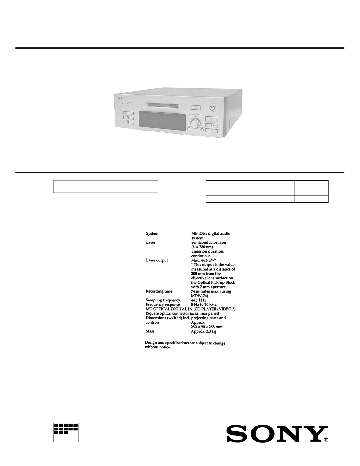
MDS-EX77
MINI DISC DECK
SERVICE MANUAL
AEP Model
UK Model
E Model
Model Name Using Similar Mechanism MDS-S37
MD Mechanism Type
MDM-3A
Optical Pick-up Name KMS-260A/J1N
U.S and foreign patents licensed from Dolb y Laboratories Licensing Corporation.
SPECIFICATIONS
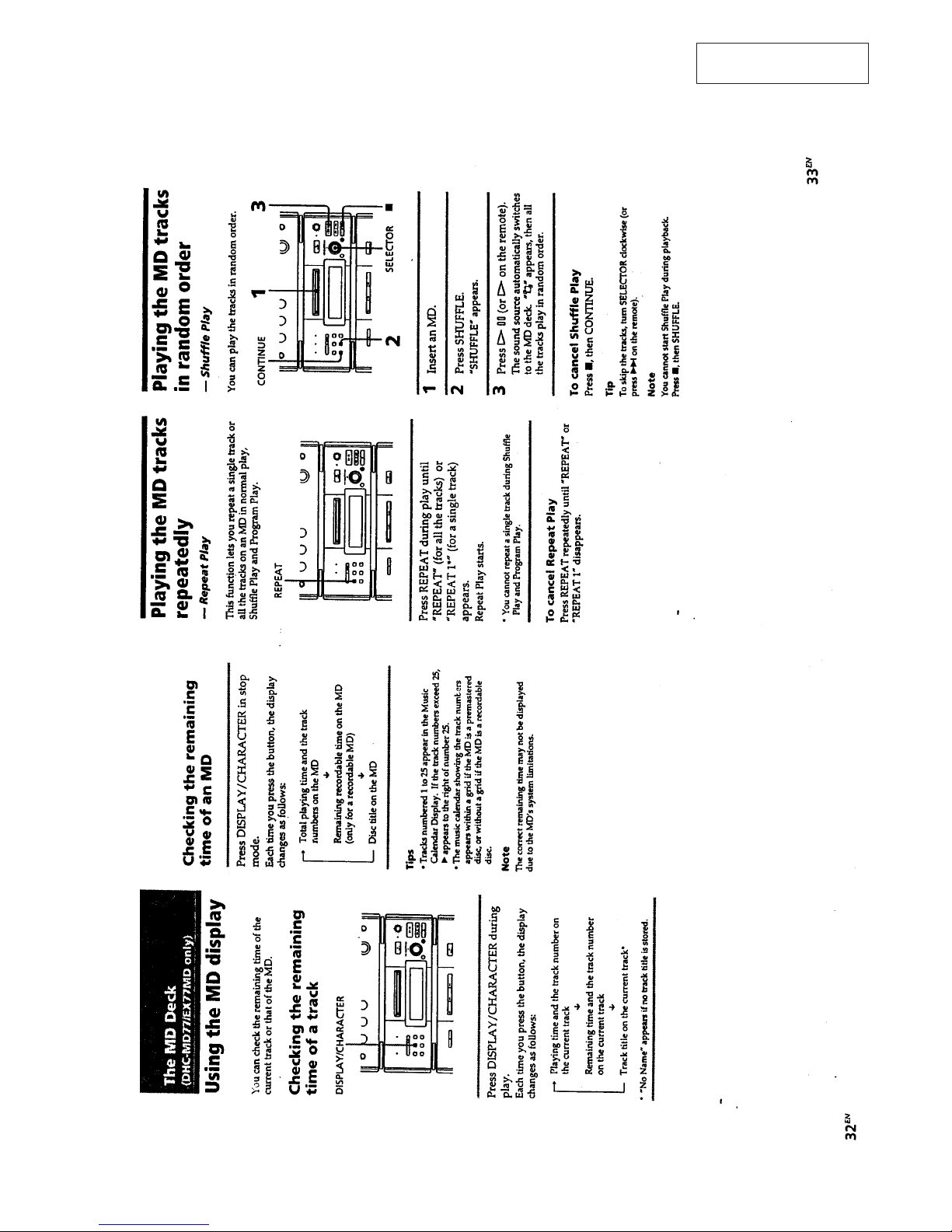
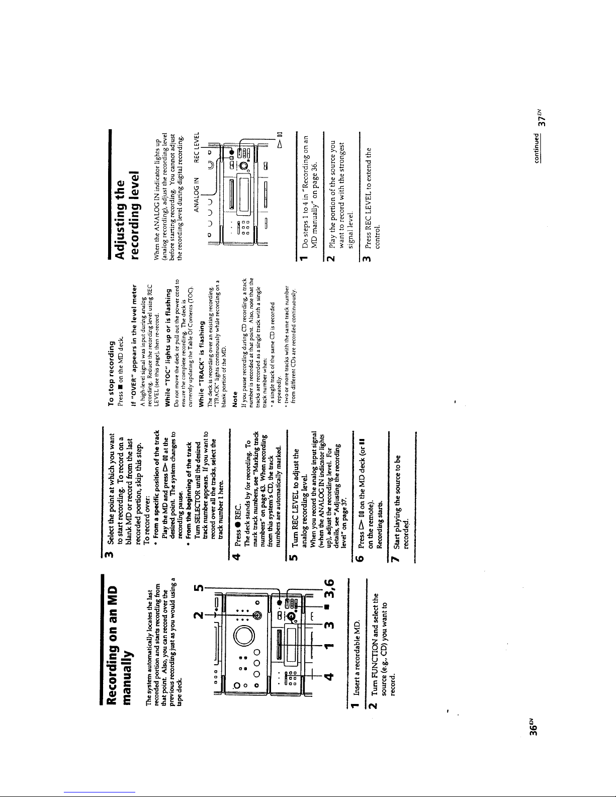
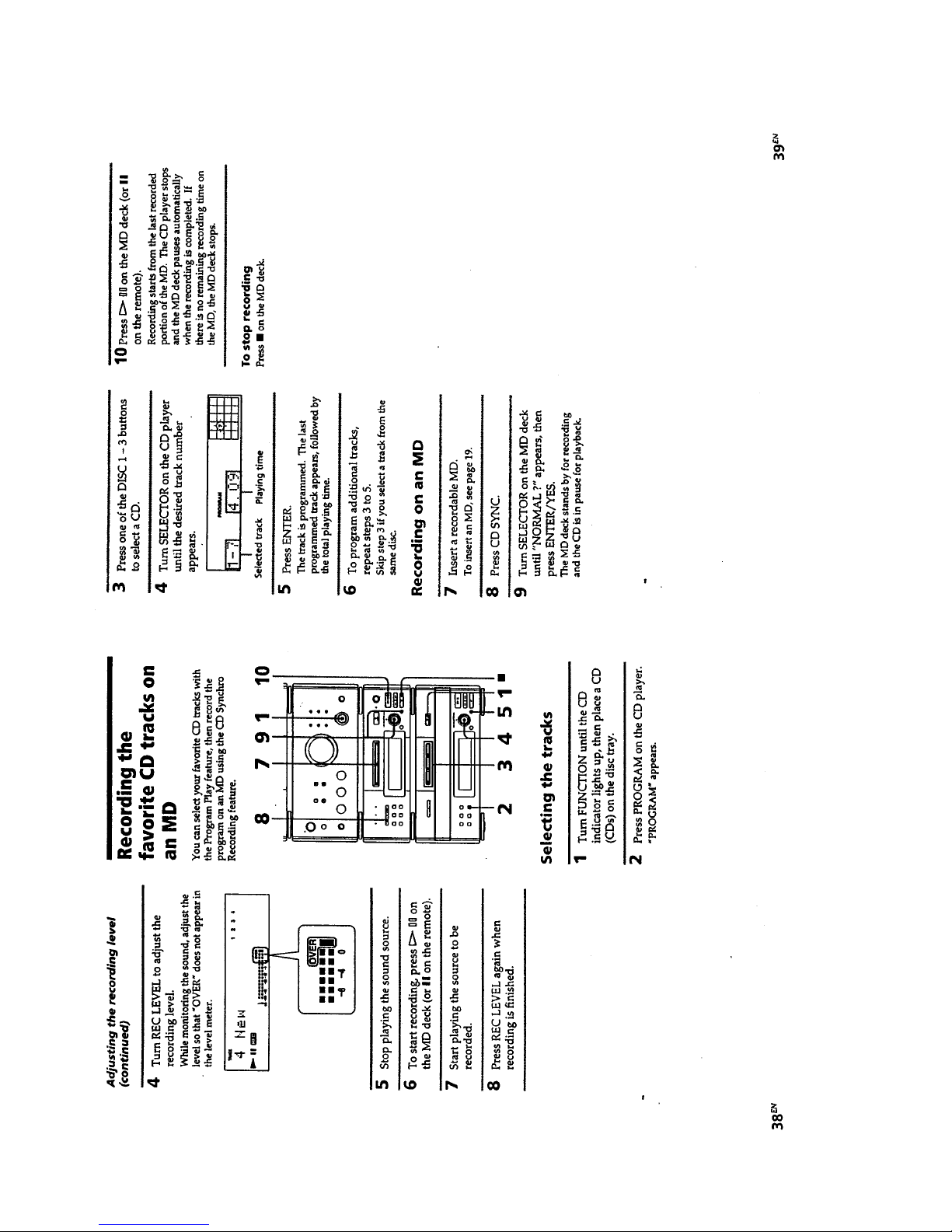
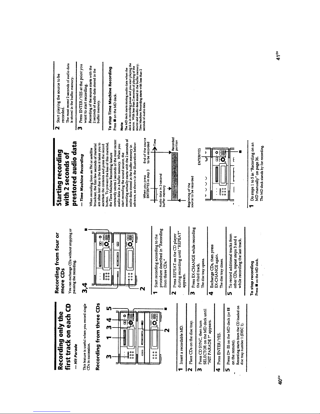
MDS-EX77 is the mini disc deck
section in DHC-MD77/EX77MD.
– 2 –
NOTES ON HANDLING THE OPTICAL PICK-UP
BLOCK OR BASE UNIT
The laser diode in the optical pick-up block may suffer electrostatic break-down because of the potential difference generated
by the charged electrostatic load, etc. on clothing and the human
body.
During repair, pay attention to electrostatic break-down and also
use the procedure in the printed matter which is included in the
repair parts.
The flexible board is easily damaged and should be handled with
care.
NOTES ON LASER DIODE EMISSION CHECK
The laser beam on this model is concentrated so as to be focused
on the disc reflective surface by the objective lens in the optical
pick-up block. Therefore, when checking the laser diode emission, observe from more than 30 cm away from the objective lens.
Notes on chip component replacement
• Never reuse a disconnected chip component.
• Notice that the minus side of a tantalum capacitor may be dam-
aged by heat.
Flexible Circuit Board Repairing
• Keep the temperature of the soldering iron around 270 ˚C dur-
ing repairing.
• Do not touch the soldering iron on the same conductor of the
circuit board (within 3 times).
• Be careful not to apply force on the conductor when soldering
or unsoldering.
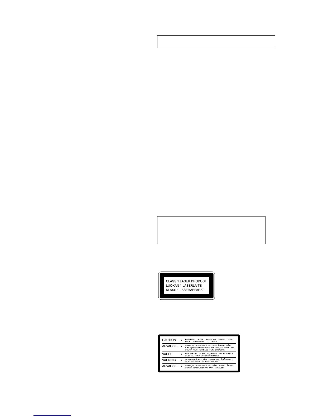
This appliance is classified as a CLASS 1 LASER product.
The CLASS 1 LASER PRODUCT MARKING is located on
the rear exterior.
Laser component in this product is capable of emitting radiation
exceeding the limit for Class 1.
The following caution label is located inside the unit.
CAUTION
Use of controls or adjustments or performance of
procedures other than those specified herein may
result in hazardous radiation exposure.
TABLE OF CONTENTS
1. SERVICING NOTES
1-1. Power Supply During Servicing..................................... 4
1-2. Flourescent Indicator Tube/Buttons/
Jog and LEDs Check Mode............................................ 4
1-3. Selection of Input Signal ................................................ 4
1-4. Retry Cause Display Mode at Record ............................ 5
2. GENERAL .................................................................. 7
3. DISASSEMBLY ........................................................ 19
4. TEST MODE
4-1. Precautions for Use of Test Mode .................................. 24
4-2. Setting the Test Mode ..................................................... 24
4-3. Releasing the Test Mode ................................................ 24
4-4. Basic Operations of the Test Mode ................................ 24
4-5. Selecting the Test Mode ................................................. 24
4-6. Operating the Continuous Playback Mode..................... 25
4-7. Operating the Continuous Recording Mode................... 25
4-8. EEP Mode....................................................................... 26
4-9. Functions of Other Buttons ............................................ 26
4-10. Test Mode Displays ........................................................ 26
4-11. Meanings of Other Displays........................................... 26
5. ELECTRICAL ADJUSTMENTS
5-1. Precautions for Checking Laser Diode Emission ........... 27
5-2. Precautions for Use of Optical Pick-up (KMS-260A) ... 27
5-3. Precautions for Adjustments........................................... 27
5-4. Creating MO Continuously Recorded Disc.................... 27
5-5. Temperature Compensation Offset Adjustment ............. 28
5-6. Laser Power Adjustment ................................................. 28
5-7. Traverse (E-F Balance) Adjustment ............................... 29
5-8. Focus Bias Adjustment................................................... 30
5-9. Error Rate Check ............................................................ 30
5-10. Focus Bias Check ........................................................... 30
5-11. Adjusting Points and Connecting Points ........................ 31
6. DIAGRAMS
6-1. Block Diagram (1/2)....................................................... 33
6-2. Block Diagram (2/2)....................................................... 35
6-3. Printed Wiring Boards
– MD MECHANISM DECK Section – ......................... 38
6-4. Schematic Diagram
– MD MECHANISM DECK Section – ......................... 41
6-5. Schematic Diagram
– MAIN/DISPLAY Section – ......................................... 46
6-6. Printed Wiring Boards
– MAIN/DISPLAY Section – ......................................... 51
6-7. IC Pin Function Description........................................... 59
7. EXPLODED VIEWS ................................................ 68
8. ELECTRICAL PARTS LIST ................................. 71
SAFETY-RELATED COMPONENT WARNING!!
COMPONENTS IDENTIFIED BY MARK ! OR DOTTED LINE
WITH MARK ! ON THE SCHEMATIC DIAGRAMS AND IN
THE PARTS LIST ARE CRITICAL TO SAFE OPERATION.
REPLACE THESE COMPONENTS WITH SONY PARTS WHOSE
PART NUMBERS APPEAR AS SHOWN IN THIS MANUAL
OR IN SUPPLEMENTS PUBLISHED BY SONY.

– 3 –
CAUTION
Danger of explosion if battery is incorrectly replaced.
Replace only with the same or equivalent type recommended by
the manufacturer.
Discard used batteries according to the manufacturer’s instructions.
ADV ARSEL!
Lithiumbatteri-Eksplosionsfare ved fejlagtig håndtering.
Udskiftning må kun ske med batteri
af samme fabrikat og type.
Levér det brugte batteri tilbage til leverandøren.
ADVARSEL
Eksplosjonsfare ved feilaktig skifte av batteri.
Benytt samme batteritype eller en tilsvarende type
anbefalt av apparatfabrikanten.
Brukte batterier kasseres i henhold til fabrikantens
instruksjoner.
VARNING
Explosionsfara vid felaktigt batteribyte.
Använd samma batterityp eller en likvärdig typ som
rekommenderas av apparattillverkaren.
Kassera använt batteri enligt gällande föreskrifter.
VAROITUS
Paristo voi räjähtää, jos se on virheellisesti asennettu.
V aihda paristo ainoastaan laitev almistajan suosittelemaan tyyppiin.
Hävitä käytetty paristo valmistajan ohjeiden mukaisesti.

– 4 –
1-1. POWER SUPPLY DURING SERVICING
This set has no power supply in it, and it does not operate individually. Therefore, connect to the pre/main amplifier system (T AEX77) for the DHC-MD77 or DHC-EX77MD in servicing. If
TA-EX77 is not available, use the power feed jig (PFJ-1) and jig
(J-2501-078-A). Using the jig, press the power switch (S408) on
the MAIN board in this set to turn on the power.
Connection:
SECTION 1
SERVICING NOTES
1-2. FLUORESCENT INDICATOR TUBE/BUTTONS/
JOG&LEDs CHECK MODE
1. While pressing the CD SYNC + CONTINUE buttons simultaneously, insert the power cord of TA-EX77 (pre/main amplifier) into the power outlet, then release the buttons. (Thus,
the check mode is activated.)
2. When buttons are released, “Key Check” is displayed for a
moment, then fluorescent indicator tubes are all turned on.
(LED for ANALOG IN indication is also turned on.)
3. As the buttons other than CD SYNC are pressed, fluorescent indicator tubes, one block each, are turned off, and all
tubes are off when operation of all buttons (except CD SYNC
button) is finished. (ANALOG IN LED is tur ned off when p
button is pressed.)
4. Press the CD SYNC button with fluorescent indicator tube
in all off status, “Key TEST OK!” is displayed for a moment,
then “JOG&LEDCheck” is displayed. (At this time,
if REPEA T button is pressed, “STANDBY” is displayed and
blinking, implying that normal operation is ready.)
5. With “JOG&LEDCheck” displayed, turning the SELECTOR
konb, and all LEDs simultaneously turn on and off repeatedly .
(If REPEAT button is pressed, normal operation is ready.)
6. With “JOG&LEDCheck” displayed, press the CD SYNC button,
and “SegmentCheck” is displayed for a moment, then segment
display is made. (If REPEAT button is pressed, normal operation is ready.)
7. Press the CD SYNC button, and “end” is displayed. Then,
press the REPEAT button to finish the check mode.
1-3. SELECTION OF INPUT SIGNAL
With the power turned on, turning the SELECTOR konb while
pressing the p button to select either of the following:
Analog in
Digital 1 in
Digital 2 in
Parts Location:
MAIN board (Component Side)
P707,909
CDP/TC
Power feed jig
(PFJ-1)
SYSTEM CONTROL connector
set
jig
(J-2501-078-A)
connector cable (17P)
(attached to the PFJ-1)
connector cable (7P)
(attached to the set)
CN904
(17P)
CN902
(7P)
CN501 (7P)
(S408)
Power switch
– 5 –
1-4. RETRY CAUSE DISPLAY MODE AT RECORD
Outline:
• In this mode, a cause of retry at recording can be displayed.
Thus, it will help find out a faulty location of the set.
• The contents displayed are data quantity stored in D-RAM, re-
try count, and retry cause. There are displayed with hexadecimal numbers.
• From the data quantity in D-RAM, whether data writing, read-
ing, storing, and ejection are executed smoothly can be confirmed. If data writing failed, data quantity will be extremely
small.
Operating Method:
1. With the po wer turned on, load a disc (use a disc for recording
of which contents may be erased).
2. Press the EDIT/NO button, and “ALL Erase?” is displayed.
3. Press the ENTER/YES button, and a message changes to
“ALL Erase??” and numbers in music calendar blink.
4. Press the ENTER/YES button, and “Complete” is displayed.
5. When “Complete” appears, immediately keep pressing the p
button for about 10 seconds.
6. When “TOC” on display disappears, release the p button.
7. Press the r REC button to start recording.
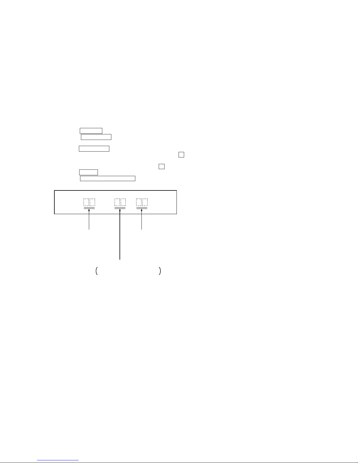
8. Press the DISPLAY/CHARACTER button, and the display
will changes as follows:
SC Rt
Data quantity in
D-RAM is displayed
at all times.
Retry cause is
displayed.
Retry count is displayed.
A numerical returns to 0 if retry
error occurred.
Note: These three kinds of displays are all made with hexadeci-
mal numbers.
9. Though Rt value increments each time retry is made, if an
error occurred, “Retry Error” is displayed and retry count returns to 0.
10. To exit from this mode, turn off the TA-EX77 (pre/main amplifier) and after “TOC” display disappeared, disconnect the
power cord of TA-EX77 from the power outlet.
Using the jig, press the power switch (S408) on the MAIN
board in this set to turn off the power.
– 6 –
Example 1: If “42” is displayed
Higher bit: 4=0100 → b6
Lower bit: 2=0010 → b1
This case shows that retry was made due to combined causes of
“CLV unlock” and “ADIP error ”.
Example 2: If “A2” is displayed
Higher bit: A=1010 → b7 + b5
Lower bit: 2=0010 → b1
This case shows that retry was made due to combined causes of
“cannot access”, “IV-R”, and “ADIP error ”.
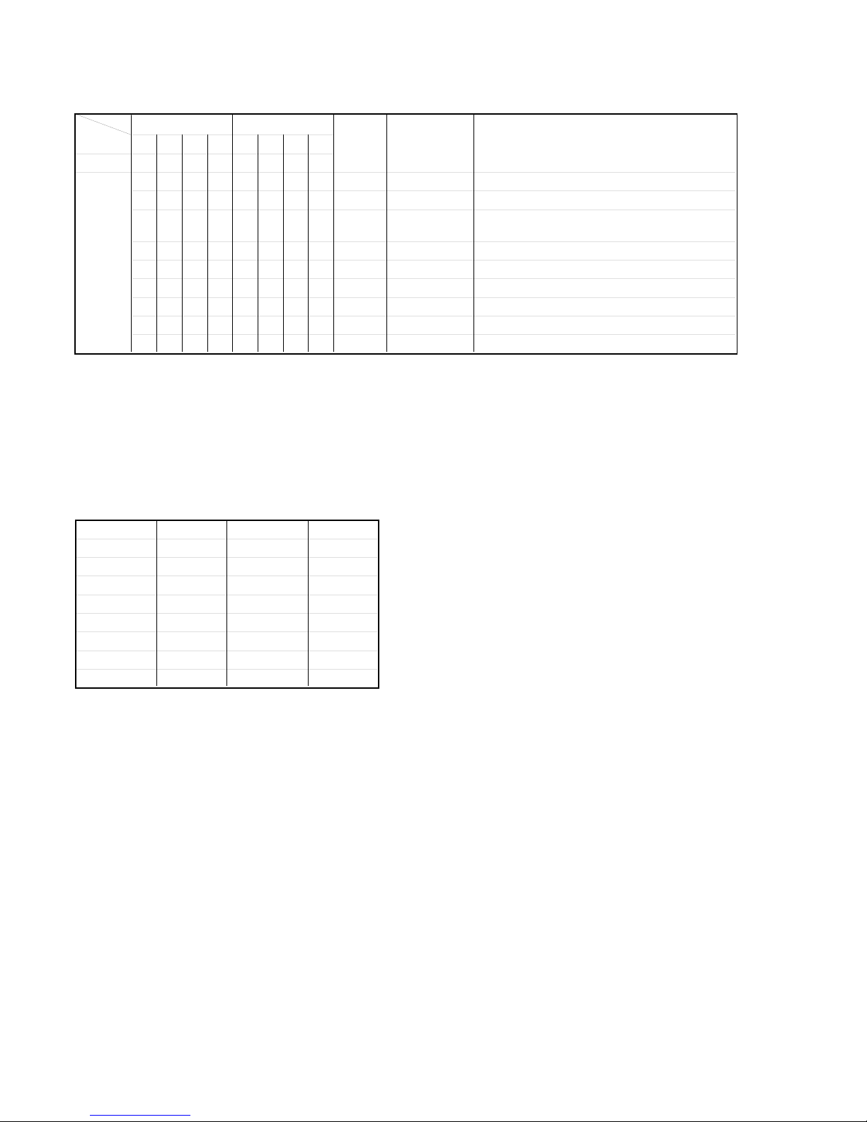
How to Use Table 1-1.:
Use table 1-1. by converting hexadecimal number of each digit
into decimal number (see table 1-2). If an error occurred by two
or more causes, respective numbers are added.
*1 Some may not be used depending on the microcomputer version.
Table 1-2. Hexadecimal number - Decimal number
Conversion
Hexadecimal Decimal Hexadecimal Decimal
0 0000 8 1000
1 0001 9 1001
2 0010 A 1010
3 0011 B 1011
4 0100 C 1100
5 0101 D 1101
6 0110 E 1110
7 0111 F 1111
84218421 Description
Bit b7 b6 b5 b4 b3 b2 b1 b0
00000000 00 spindle slow When spindle speed slow was detected
00000001 01 shock *1 When shock over 3.5 was detected
00000010 02 ader 5
When ADER was counted more than 5 times
successively
00000100 04 address error ADIP addresses are not serial
00001000 08 (Not used) Not used
00010000 10 focus Focusing failed
00100000 20 IV-R ABCD signal level exceeded the specified range
01000000 40 CLV unlock CLV is unlocked (CLV is out of range)
10000000 80 cannot access Access failed
Table 1-1. Description of Retry Cause Display
Hexadecimal
Lower Bit
Upper Bit
Name of
Retry Cause
Hexa-
decimal
Decimal
– 7 –
SECTION 2
GENERAL
This section is extracted
from instruction manual.

– 8 –
– 9 –
– 10 –
– 11 –
– 12 –
– 13 –
– 14 –
– 15 –
– 16 –
– 17 –
– 18 –
– 19 –
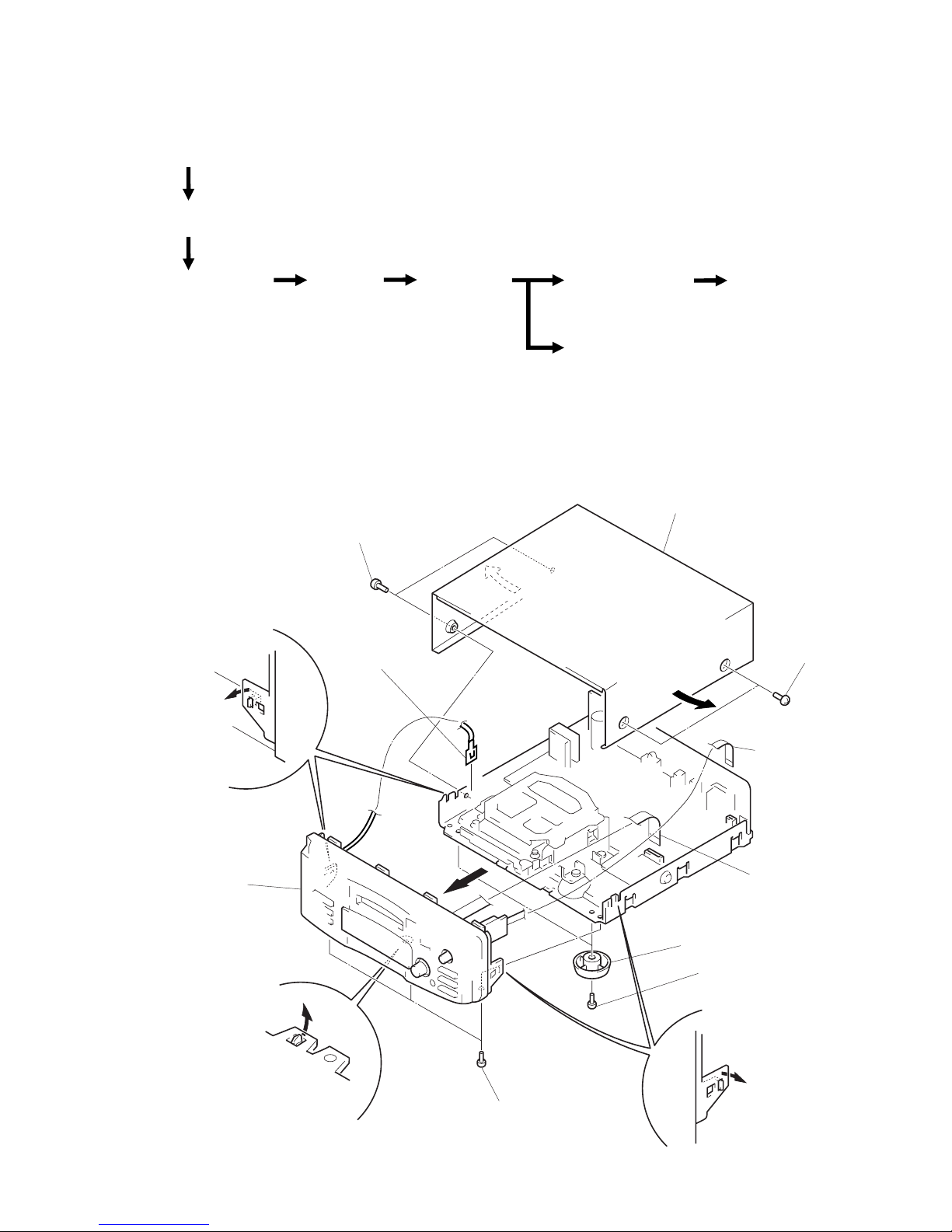
• This set can be disassembled in the order shown below.
SECTION 3
DISASSEMBLY
SHUTTER ASS'Y
(Page 22)
OVER WRITE HEAD
(Page 22)
SLIDER COMPLETE
ASS'Y
(Page 23)
NOTE FOR
INSTALLATION
• SLIDER COMPLETE
ASS'Y (Page 23)
BD BOARD
(Page 21)
BRACKET (T), (L), (R)
(Page 20)
MECHANISM DECK
(Page 20)
CASE, FRONT PANEL
SECTION (Page 19)
SUB CHASSIS
(Page 21)
Note: Follow the disassembly procedure in the numerical order given.
9
lead
(with connector)
8
claw
4
two legs (F)
3
two screws
(BV3
×
10)
7
flat wire (19 Core)
(CN700)
6
flat wire (5 Core)
(CN800)
1
two screws
(case 3 TP2)
2
case
1
two screws
(case 3 TP2)
!º
front panel
section
CASE, FRONT PANEL SECTION
5
three screws
(BV3
×
10)
8
claw
8
claw
– 20 –
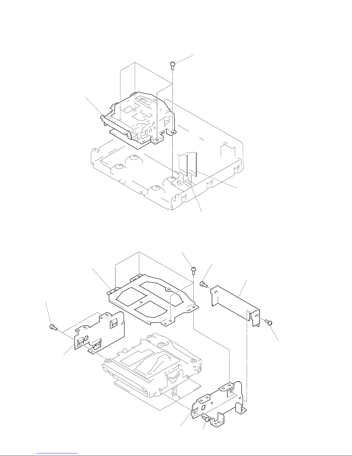
MECHANISM DECK
BRACKET (T), (L), (R)
3
four screws
(BVTT3
×
6)
4
mechanism deck
1
flat wire (29 core)
(CN402)
2
flat wire (19 core)
(CN401)
4
bracket
(joint)
5
two screws
(BVTT2
×
3)
6
bracket (L)
8
bracket (R)
7
two screws
(BVTT2
×
3)
3
screw
(BVTT2
×
3)
3
screw
(BVTT2
×
3)
1
four screws
(BVTT2
×
3)
2
bracket (T)
– 21 –
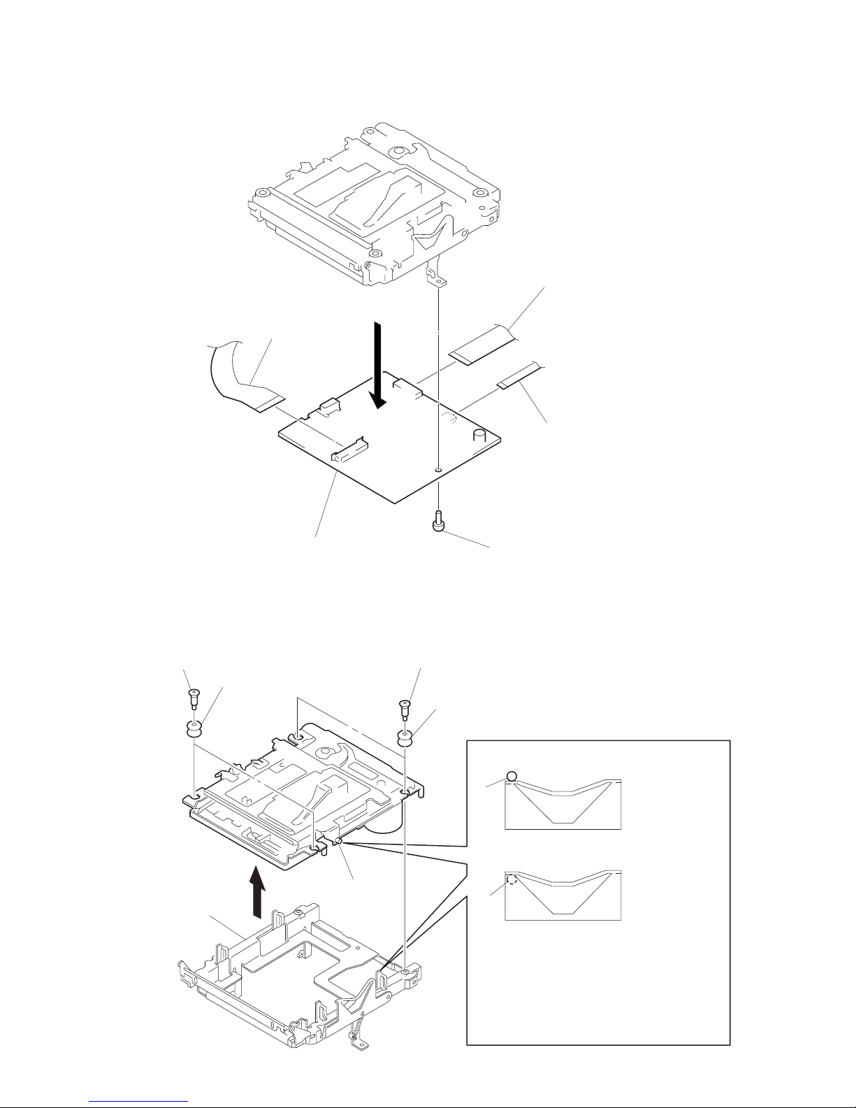
SUB CHASSIS
1
two step screws
2
two insulators
1
two step screws
2
two insulators
part
A
NG
OK
Take care so that the part
A
may be right position when installing.
part
A
BD BOARD
3
sub chassis
part
A
1
flexible board
(over write head)
3
screws (BVTT2 × 4)
5
BD board
4
OP relay
flexible board
(CN101)
2
flat cable (15 core)
(CN106)
– 22 –
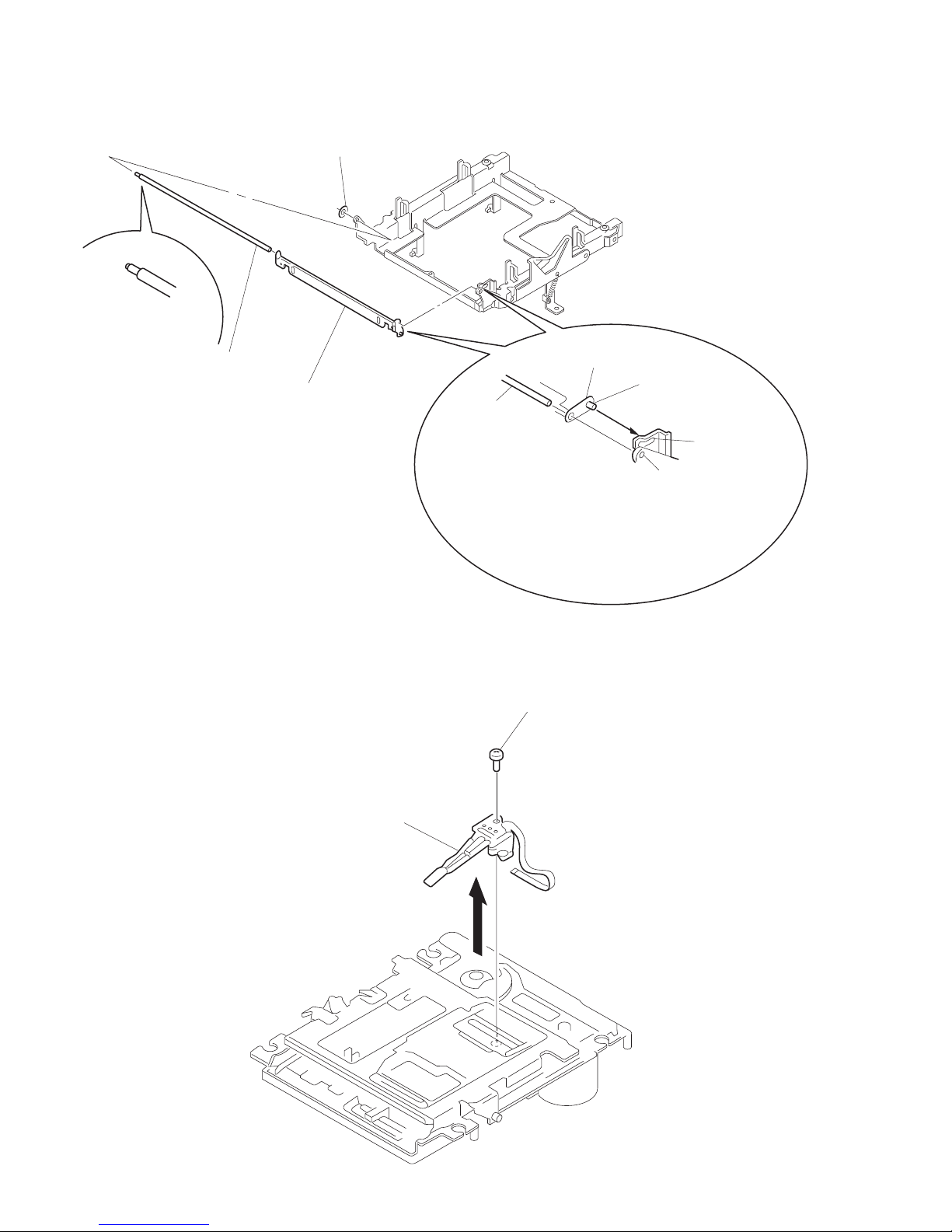
OVER WRITE HEAD
2
over write head
1
screw (P1.7 × 6)
SHUTTER ASS’Y
1
stopper washer
2
shaft (shutter) A
3
shutter ass’y
shutter ass’y
shaft (shutter) B
hole B
hole A
When installing, install the shaft (shutter) A
into the hole as show in the figune before
installing the shaft (shutter) B into the hole B.
shaft (shutter) A
 Loading...