

Page 1

2-347-256-11(1)
Mini-disc Recorder
MDS-E10
Operating Instructions
Thank you very much for purchasing this Sony product.
Sony products are designed with safety in mind. If electrical
products are used incorrectly, however, there is a risk of death
or serious injury, so be sure to obey the following to avoid
accidents.
TABLE OF CONTENTS
Warning......................................
Location and Function of Parts
Getting Started ..........................
Recording on MDs ....................
Playing MDs...............................
Editing Recorded MDs..............
Other Functions ........................
Operating the MD Recorder
Using a Keyboard ..................
Additinal Information................
2
6
15
18
27
40
52
55
60
2000 Sony Corporation
Page 2
WARNING
Notice for the Customers in
the United Kingdom
IMPORTANT
The wires in this mains lead are
coloured in accordance with the
following code:
Blue: Neutral
Brown: Live
As the colours of the wires in the mains
lead of this apparatus may not
correspond with the coloured markings
identifying the terminals in your plug,
proceed as follows:
The wire which is coloured blue must
be connected to the terminal which is
marked with the letter N or coloured
black.
The wire which is coloured brown
must be connected to the terminal
which is marked with the letter L or
coloured red. Do not connect either
wire to the earth terminal in the plug
which is marked by the letter E or by
the safety earth symbol I or coloured
green or green-and-yellow.
For customers in the U.S.A.
To prevent fire or shock
hazard, do not expose the
unit to rain or moisture.
To avoid electrical shock, do
not open the cabinet. Refer
servicing to qualified
personnel only.
This symbol is intended to alert
the user to the presence of
uninsulated “dangerous
voltage” within the product’s
enclosure that may be of
sufficient magnitude to
constitute a risk of electric
shock to persons.
This symbol is intended to alert
the user to the presence of
important operating and
maintenance (servicing)
instructions in the literature
accompanying the appliance.
CAUTION
You are cautioned that any changes or
modification not expressly approved in
this manual could void your authority
to operate this equipment.
INFORMATION
This equipment has been tested and
found to comply with the limits for a
Class B digital device, pursuant to Part
15 of the FCC Rules. These limits are
designed to provide reasonable
protection against harmful interference
in a residential installation. This
equipment generates, uses, and can
radiate radio frequency energy and, if
not installed and used in accordance
with the instructions, may cause
harmful interference to radio
communications.
However, there is no guarantee that
interference will not occur in a
particular installation. If this equipment
does cause harmful interference to
radio or television reception, which can
be determined by turning the
equipment off and on, the user is
encouraged to try to correct the
interference by one or more of the
following measures:
• Reorient or relocate the receiving
antenna.
• Increase the separation between the
equipment and receiver.
• Connect the equipment into an outlet
on a circuit different from that to
which the receiver is connected.
• Consult the dealer or an experienced
radio/TV technician for help.
For customers in the Europe.
The laser component in this product
is capable of emitting radiation
exceeding the limit for Class 1.
This appliance is classified as a CLASS
1 LASER product.
The CLASS 1 LASER PRODUCT
MARKING is located on the rear
exterior.
The following caution label is located
inside the unit.
For customers in Canada
This ClassB digital apparatus complies
With Canadian ICES-003.
CAUTION
TO PREVENT ELECTRIC SHOCK, DO
NOT USE THS POLARIZED AC PLUG
WITH AN EXTENSION CORD,
RECEPTACLE OR OTHER OUTLET
UNLESS THE BLADES CAN BE
FULLY INSERTED TO PREVENT
BLADE EXPOSURE.
ATTENTION
POUR PREVENIR LES CHOCS
ELECTRIQUES, NE PAS UTILISER
CETTE FICHE POLARISEE AVEC
UNPROLONGATEUR, UNE PRISE DE
COURANT OU UNE AUTRE SORITIE
DE COURANT SAUF SI LES LAMES
PEUVENT ETRE INSEREES A FOND
SANS EN LAISSER AUCUNE PARTIE
A DECOUVERT.
Setting the voltage selector
(voltage selector equipped
models only)
Check that the voltage selector on the
rear panel is set to the local power line
voltage. If not, set the selector to the
correct position using a screwdriver
before connecting the AC power cord to
a wall outlet.
230V
120V
VOLTAGE
SELECTOR
Owner’s Record
The model and serial numbers are
located on the rear of the unit. Record
the serial number in the space provided
below. Refer to them whenever you call
upon your Sony dealer regarding this
product.
Model No. ___________
Serial No. ___________
IN NO EVENT SHALL SELLER BE
LIABLE FOR ANY DIRECT,
INCIDENTAL OR
CONSEQUENTIAL DAMAGES OF
ANY NATURE, OR LOSSES OR
EXPENSES RESULTING FROM
ANY DEFECTIVE PRODUCT OR
THE USE OF ANY PRODUCT.
2
Page 3

Precautions
On safety
• Should any solid object or liquid fall into the cabinet,
unplug the recorder and have it checked by qualified
personnel before operating it any further.
• Caution – The use of optical instruments with this
product will increase eye hazard.
On power sources
• Before operating the recorder, check that the
operating voltage of the recorder is identical with
your local power supply. The operating voltage is
indicated on the nameplate at the rear of the
recorder.
• The unit is not disconnected from the AC power
source (mains) as long as it is connected to the wall
outlet, even if the unit itself has been turned off.
• If you are not going to use the recorder for a long
time, be sure to disconnect the recorder from the
wall outlet. To disconnect the AC power cord, grasp
the plug itself; never pull the cord.
• AC power cord must be changed only at the
qualified service shop.
On condensation
If the recorder is brought directly from a cold to a
warm location, or is placed in a very damp room,
moisture may condense on the lenses inside the
recorder. Should this occur, the recorder may not
operate properly. In this case, remove the MD and
leave the recorder turned on for several hours until the
moisture evaporates.
On cleaning
Clean the cabinet, panel and controls with a soft cloth
slightly moistened with mild detergent solution. Do
not use any type of abrasive pad, scouring powder or
solvent such as alcohol or benzine.
If you have any questions or problems concerning
your recorder, please consult your nearest Sony dealer.
3
Page 4
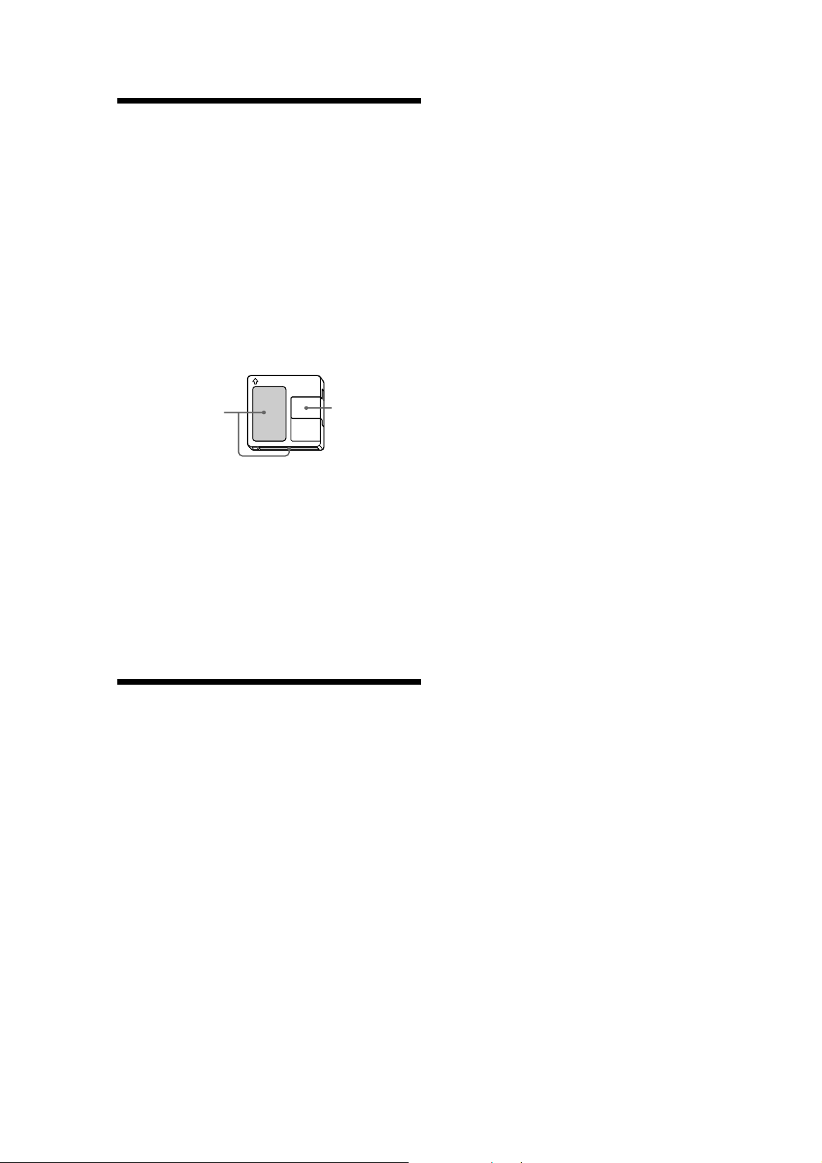
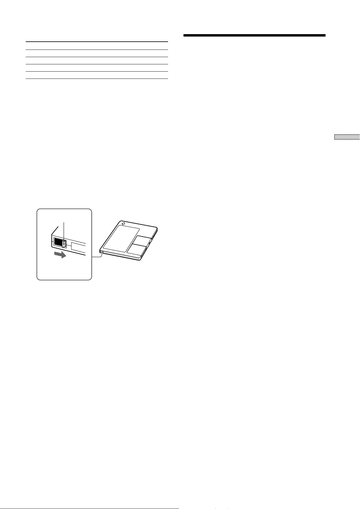
Handling MDs
The MD is enclosed in a cartridge to protect the disc
from debris or fingerprints and to make it easy to
handle. However, the presence of debris or a warped
cartridge may inhibit the disc from operating properly.
To ensure that you can always listen to the highest
quality music, follow the precautions below:
• Do not touch the internal disc directly. Forcing the
shutter open may damage the internal disc.
• Be sure to stick the labels supplied with the md to
the appropriate positions. The shape of the labels
may vary depending on the MD brand.
Proper Location
of the labels
Where to keep thge MDs
Do not place the cartridge where it may be exposed to
direct sunlight or extremely high heat and humidity.
Regular maintenance
Wipe dust and debris from the surface of the cartridge
with a dry cloth.
Shutter
About This Manual
Conventions
• Controls in the instructions are those on the recorder;
these may, however, be substituted by controls on the
remote that are similarly named or, when
different, appear in the instructions within brackets.
• The following icons are used in this manual;
Z
z
Indicates a procedure that
requires use of the remote.
Indicates tips for making the
task easier and hints.
4
Page 5

TABLE OF CONTENTS
Location and Function of Parts.........6
Front Panel Descriptions .............................................. 7
Rear Panel Descriptions................................................ 8
Remote Descriptions ..................................................... 9
Display Window Descriptions ................................... 11
Using the Display Window........................................ 12
Getting Started ................................15
After Unpacking .......................................................... 15
Hooking Up the Audio Components........................ 16
Recording on MDs............................ 18
Recording on an MD ................................................... 18
Notes on Recording ..................................................... 19
Recording for a long time ........................................... 20
Adjusting the Recording Level .................................. 21
Recording Tips ............................................................. 22
Marking Track Numbers While Recording
(Track Marking)...................................................... 23
Starting Recording With 6 Seconds of Prestored
Audio Data (Time Machine Recording).............. 24
Synchro-recording With the Audio Component of
Your Choice (Music Synchro-recording) ............ 25
Synchro-recording With a Sony CD Player
(CD Synchro-recording) ........................................ 25
Playing MDs ......................................27
Editing Recorded MDs .....................40
Before you start editing............................................... 40
Erasing Tracks (ERASE).............................................. 41
Combining Tracks (COMBINE)................................. 43
Moving Tracks (MOVE) .............................................. 44
Dividing Tracks (DIVIDE) .......................................... 45
Naming a Track or MD (NAME)............................... 46
Undoing the Last Edit (UNDO)................................. 50
Changing Recorded Level after Recording
(S.F Edit) .................................................................. 50
Other Functions ................................ 52
Fade IN and Fade Out................................................. 52
Notification of the track end and the disc end
(End Of Track/Disc) .............................................. 53
Control terminal functions ......................................... 53
Using a Timer ............................................................... 54
Operating the MD Recorder Using a
Keyboard...........................................55
Setting the keyboard ................................................... 55
Naming a Track or MD Using the Keyboard........... 56
Operating the Recorder Through the Keyboard ..... 57
Assigning Characters to Keyboard Keys.................. 58
Keyboard Operations (English Keyboard Layout) . 59
Keyboard Operations (10-Keyboard Layout) .......... 59
Location and Function of Parts
Playing an MD ............................................................. 27
Playing a Specific Track .............................................. 29
Locating a Particular Point in a Track....................... 30
Playing Tracks Repeatedly (Repeat Play)................. 31
Playing Tracks in Random Order (Shuffle Play) ..... 32
Creating Your Own Program (Program Play) ......... 33
Storing the Located Track to Start Play Instantane-
ously (Multi-access Play) ...................................... 34
Setting Play Start Position After Play Is Stopped
(Resume Play) ......................................................... 36
Returning to the Specified Point (Locate Play) ....... 36
Pausing After Each Track (Auto Pause) ................... 37
Making Track Play Start Soon (Auto Cue) ............... 38
Changing the Playback Speed
(Variable Speed Play) ............................................. 39
Additional Information.................... 60
System Limitations ...................................................... 60
Trouble shooting .......................................................... 61
Self-Diagnosis Function .............................................. 62
Display Messages ........................................................ 63
Specifications................................................................ 64
Exterior dimensions .................................................... 65
Setup Menu Table........................................................ 66
Edit Menu Table........................................................... 67
Last Mode Memory ..................................................... 67
5
Page 6

Location and
Function of Parts
6
Page 7
Preparation
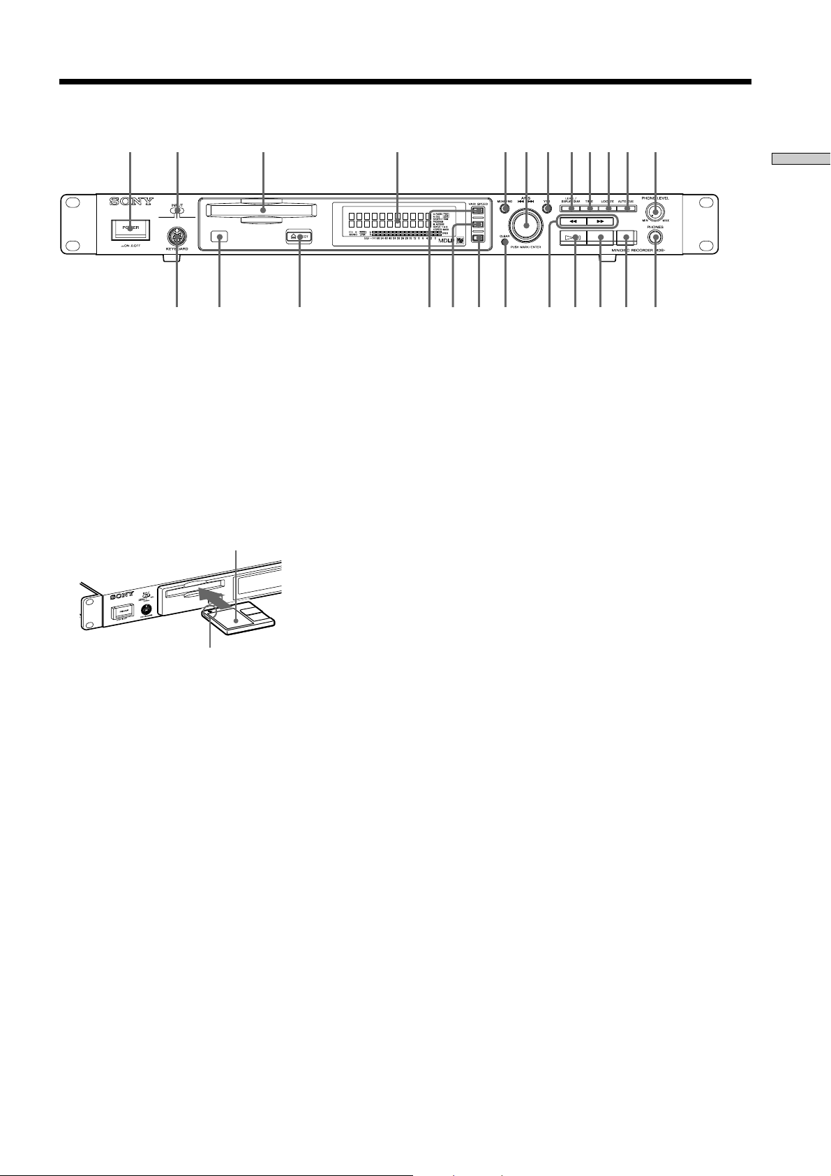
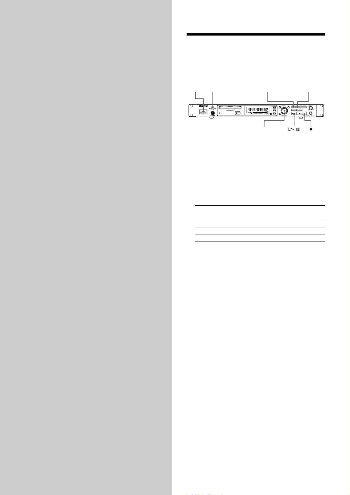
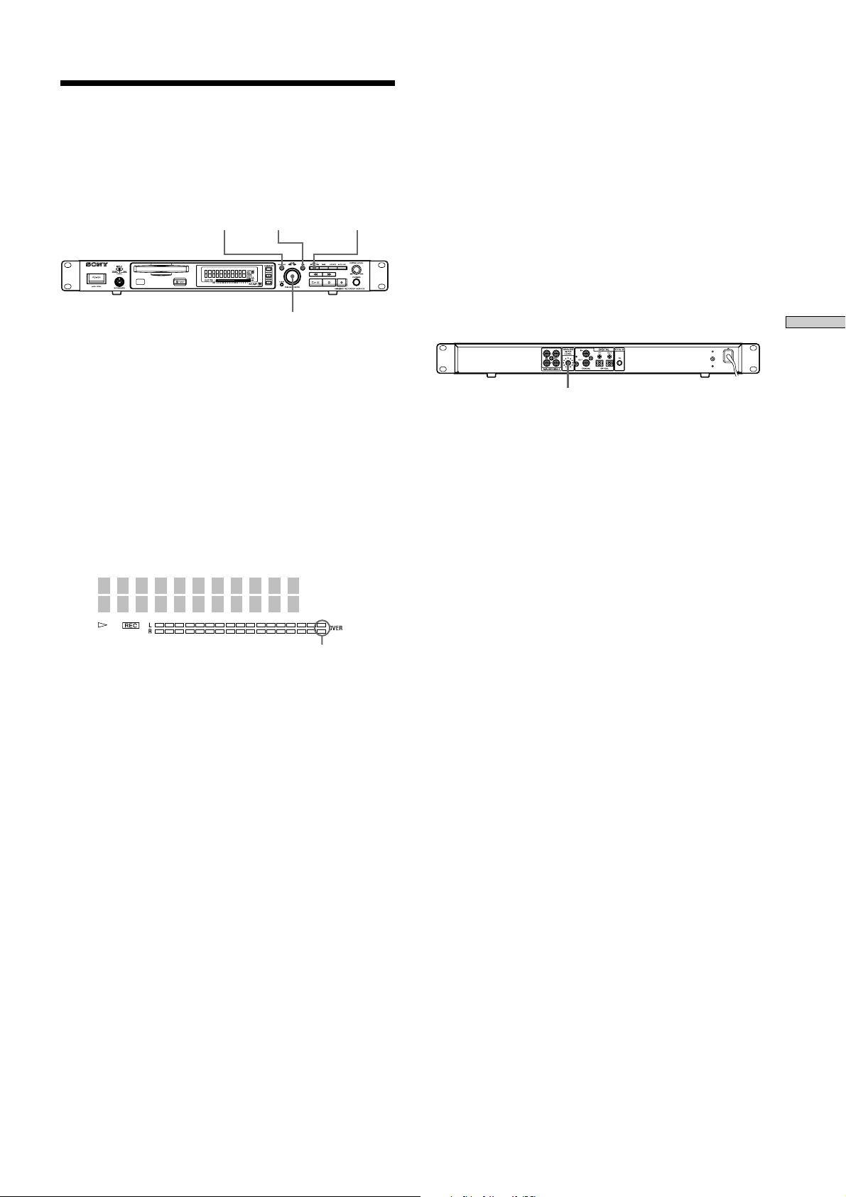
Front Panel Descriptions
11 2 3 4 5 7 89q;q a qs6
qd qf qg qk ql wa ws wd wfqh qj w;
Location and Function of Parts
1 POWER button
Press to turn the recorder on. When you press the
button again, the recorder turns off.
2 INPUT selector
Use to select the input jack (or connector) of the
program source to be recorded.
3 MD insertion slot
Insert the MD as illustrated below.
With the labeled side up
With the arrow pointing
towards the recorder
4 Display window
Shows various information.
5 MENU/NO button
Press to display “Edit Menu” or “Setup Menu.”
Also, the MENU mode is cleared.
6 AMS control (MARK/ENTER button)
Turn to locate tracks, adjust the recording level, select
the input characters, or select a menu item and a
setting value.
7 YES button
Press to carry out the selected operation.
8 LEVEL/DISPLAY/CHAR button
Press to display INPUT or OUTPUT level and disc or
track information, select the type of characters to be
input, and change to time display.
9 TIME button
Press to change time information on the disc or track.
0 LOCATE button
Press to locate pre-marked positions.
!¡ AUTO CUE button
Press to set AUTO CUE, AUTO PAUSE, or OFF.
!™ PHONE LEVEL control
Use to adjust the volume of the headphones.
!£ KEYBOARD jack
Connect a keyboard to this jack.
!¢ Remote sensor
Receives the infrared signal of the remote for remote
operations.
!∞ Z EJECT button
Press to eject the MD.
!§ VARI SPEED button
Press to turn on and off VARI SPEED.
!¶ VARI SPEED + button
Press to increase play speed at 0.5% step when VARI
SPEED is on.
!• VARI SPEED _ button
Press to decrease play speed at 0.5% step when VARI
SPEED is on.
!ª CLEAR button
Press to cancel the selection.
@º m/M (backward/forward) button
Press to lacate a portion whithin a track, change the
contens of a program, or change the input character.
@¡ 7 (play/pause) button
Press to start play and pause or resume play or
recording.
@™ x (stop) button
Press to stop play or recording, or cancel the selected
operation.
@£ z (record) button
Press to record on the MD, monitor the input signal, or
mark track numbers.
@¢ PHONES jack
Connect headphones to this jack.
7
Page 8
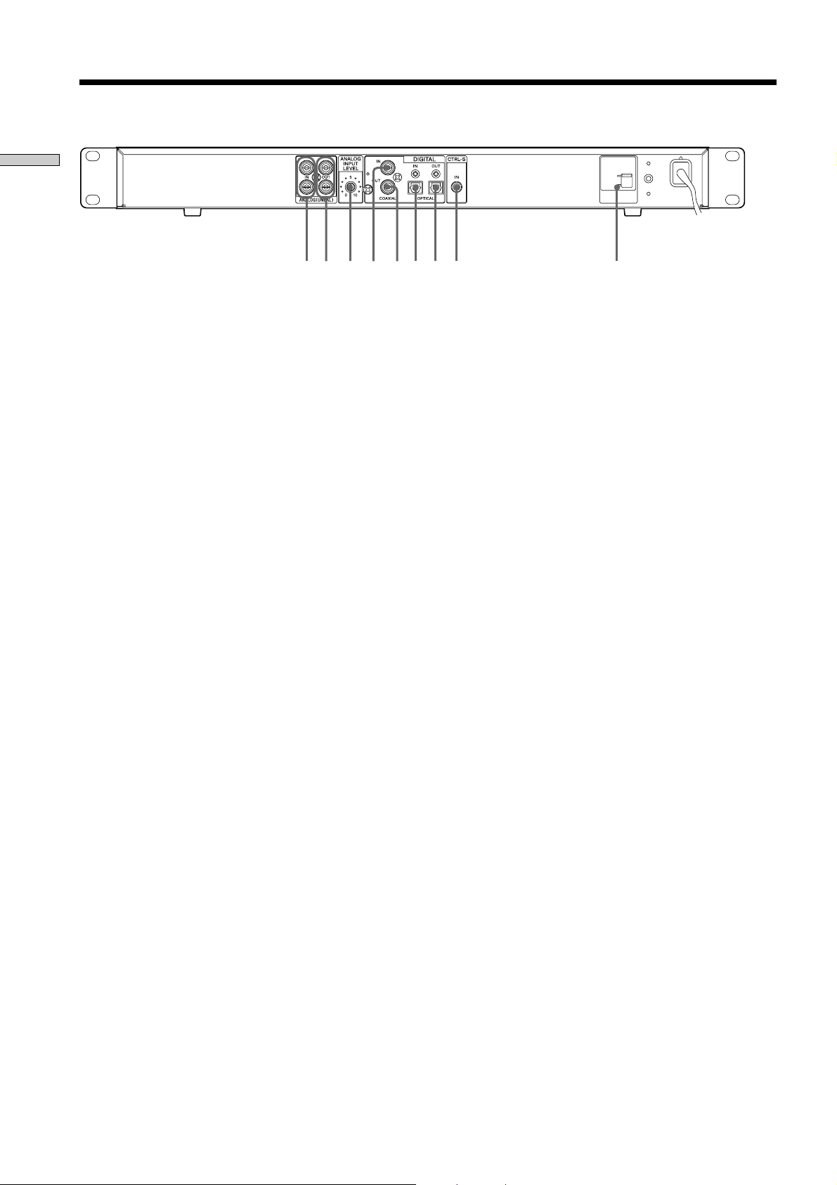
Rear Panel Descriptions
Location and Function of Parts
1 ANALOG (UNBALANCE) input jacks
Inputs as an analog signal the sound of the component
connected by a pin type connecting cable.
2 ANALOG (UNBALANCE) output jacks
Outputs as an analog signal the contents of the MD of
this recorder to the component connected by a pin type
connecting cable.
3 ANALOG INPUT LEVEL control
Can adjust the level of analog input in a range of _ ∞ ~
+15 dB.
Normally, this control is used in the position (0 dB) of
center click.
4 DIGITAL COAXIAL input jack
Inputs as a digital signal the sound of the connected
component.
12 6783 4 5
230V
120V
VOLTAG E
SELECTOR
9
5 DIGITAL COAXIAL output jack
Outputs an a digital signal the contents of the MD of
the recorder to the connected component.
6 DIGITAL OPTICAL input connector
Inputs as a digital signal the sound of the connected
component.
7 DIGITAL OPTICAL output connector
Outputs an a digital signal the contents of the MD of
the recorder to the connected component.
8 CONTROL-S jack
Connects the remote or control equipment.
If the plug is connected to the jack, the remote sensor
does not receive infrared rays.
9 VOLTAGE selector
(Exept for the USA/CA models)
Select 120V or 230V according to the local power line
voltage. (Refer to page 2)
8
Page 9
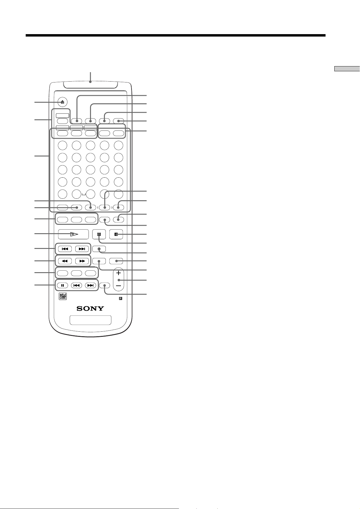
Remote Descriptions
wk
EJECT
1
PLAY MODE
2
3
4
5
6
7
8
9
q;
qa
M.ACCESS
CONTINUE SHUFFLE PROGRAM
ABCDE
FGHIJ
12345
KLMNO
678910
PQRST
11 12 13 14 15
UVWXY
16 17 18 19 20
Z
21 22 23 24 25
/
>25 ?!
NAME CHAR
STOP START
TIME
DISPLAY
-
NAME IN
CD-SYNC
CD PLAYER
MINIDISC DECK
.
BA
NUM
T.REC MUSIC SYNC
STANDBY
YES
MENU/NO
DATE
RECORDED PRESENT
,
A.CUE
M.SCANA.PAUSEREPEAT
CLEAR SCROLL
FADER
LEVEL
RM-DR1
qs
qd
qf
qg
qh
qj
qk
ql
w;
wa
ws
wd
wf
wg
wh
wj
5 REPEAT button
Press to select ALL repeat, one track repeat, or repeat
off.
6 NAME button
Press to add the name or change the name of a track or
MD.
CHAR button
Press to select the type of characters to be input.
NUM button
Press to input numbers.
7 H (play) button
Press to start play.
8 ./> (locating tracks) button
Press to locate tracks, adjust the recording level, or
select a menu item and a setting value.
9 m/M (backward/forward) button
Press to locate a portion within a track, change the
contents of a program, or change the input character.
0 CD-SYNCHRO button
Press to operate the CD-Synchro-recording of a CD
component.
!¡ CD PLAYER button
Press to pause or locate tracks the CD component.
!™ DISPLAY button
Press to select the information to be displayed in the
window.
!£ TIME button
Press to change the disc or track time information.
!¢ MENU/NO button
Press to display “Edit Menu” or “Setup Menu.” The
MENU mode is cleared.
!∞ YES button
Press to carry out the selected operation.
Location and Function of Parts
1 Z (EJECT) button
Press to eject the MD.
2 PLAY MODE button
Press to select multi-access, normal play, Shuffle Play,
or Program Play.
3 Letter/track number input buttons
Press to input letters, numbers, symbols or select track
numbers.
4 A ↔ B button
Press to select Repeat A ↔ B Play.
!§ DATE (RECORDED/PRESENT) button
Press to display the recorded time of a disc recorded by
a component which contains a function of recording
the recorded date or display the present time of a
component which contains a clock function. (This
recorder does not contain a clock function.)
!¶ A.CUE/A.PAUSE button
Press to set AUTO CUE, AUTO PAUSE, or OFF.
9
Page 10

!• M.SCAN button
Location and Function of Parts
Press to successively play the located tracks only
for the set time.
!ª SCROLL button
Press to scroll the name of a track or MD.
@º CLEAR button
Press to cancel the selection.
@¡ x (stop) button
Press to stop play or recording, or clear the MENU
mode.
@™ X (pause) button
Press to pause or resume play or recording.
@£ z (record) button
Press to record on the MD, monitor the input signal,
or mark track numbers.
@¢ MUSIC SYNC button
Press to start Music Synchro-recording.
@∞ T.REC button
Press to start Time Machine Recording.
@§ LEVEL + / _ button
Press to adjust the recording level or output level of
analog play.
@¶ FADER button
Press to perform Fade-in Play/Recording or Fadeout Play/Recording.
@• Control-S jack
Can be used as the wired remote by connecting
with the control-S jack in the rear of the recorder
using a supplied cable.
If the plug is connected to the jack, the remote does
not radiate infrared rays.
10
Page 11

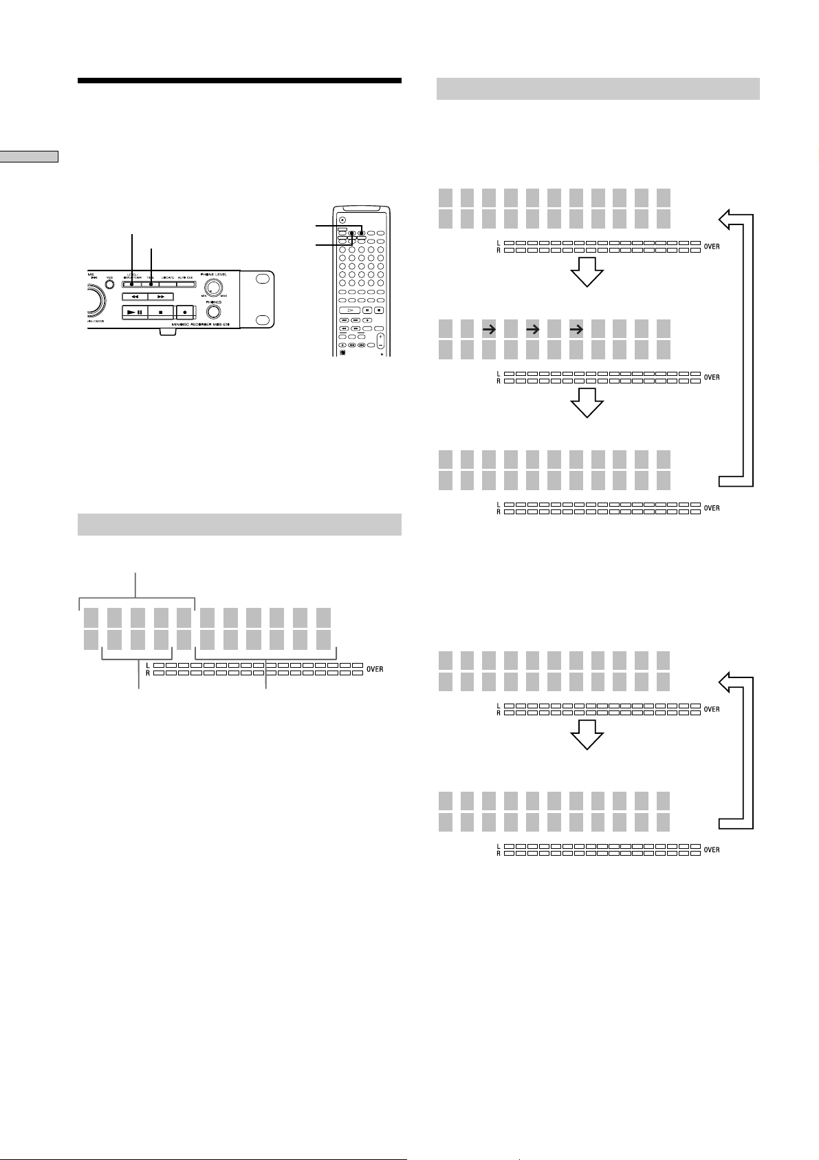
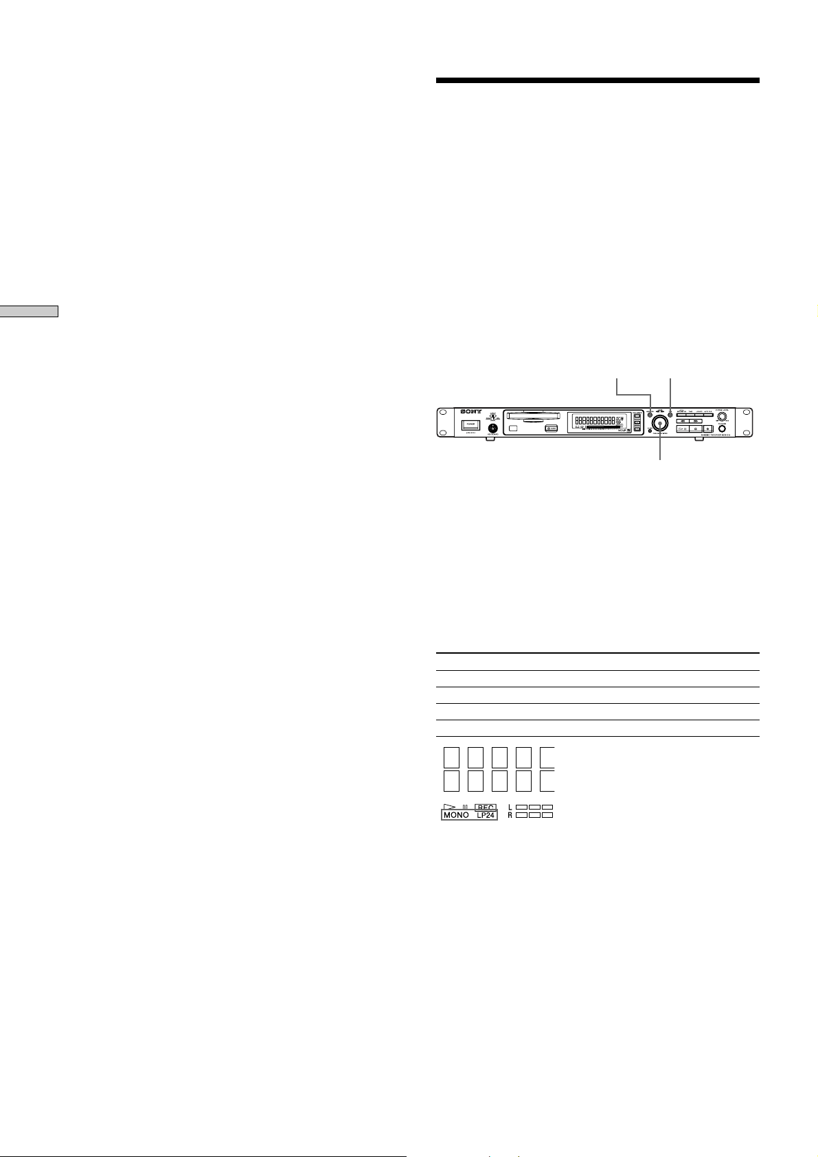
Display Window Descriptions
1 2 341
5
1 Disc, track, and time display
Displays MD information, the set contents of “Edit
Menu” or “Setup Menu,” and time information.
2 AUTO PAUSE and AUTO CUE display
Lights up when AUTO PAUSE or AUTO CUE is
selected.
3 TOC EDIT display
Displays “TOC” when record contents or edit contents
are not recorded on MD. Flashes “TOC” when they are
recorded on MD.
“TOC” is displayed during edit operation.
4 RAM display
Lights up in RAM edit mode in which temporary
editing is performed for sending without recording
editing results.
5 7 (play/pause) display
Displays during play or pause.
Location and Function of Parts
8 9q;qa6 7
7 Level meter display
Displays the loudness of the sound of play or
recording.
8 VARI SPEED display
Lights up when the VARI SPEED function is selected.
9 MARK display
Lights up when the position (MARK) of a located point
is selected.
0 REPEAT display
Displays “REPEAT” when all track repeat is selected,
“REPEAT1” when one track repeat is selected, and
“REPEAT A-B” when A-B repeat is selected.
!¡ Play mode display
Displays “SHUFFLE” when shuffle play is selected,
“PROGRAM” when program play is selected, and
“M.ACCESS” when multi-access play is selected.
6 Record and record mode display
REC display
Lights up during recording or pausing.
Record mode display
Lights up “MONO” for monaural recording, “LP2” for
double-length stereo recording, and “LP4” for 4-time
length stereo recording in record mode or mode when
the playing track is recorded.
11
Page 12
Using the Display Window
15 46m08s
Tr
SONGS
4S 12m35s
/4 1 7 5/
Coax 0.0dB
Input Level
Total number of tracks and recorded time (default display)
Level of the input signal
The contents of a program
(only when “PROGRAM” lights up)
Press
Press
PROGRAM
Press
15 46m08s
Tr
SONGS
-27m52s
SONGS
Total number of tracks and total recorded time
(default display)
Total number of tracks and remaining
recordable time on the MD
(recordable MDs only)
*
Press
Press
The display window shows information about the MD or
Location and Function of Parts
track. This section describes the information that is
displayed for each recorder status.
While the recorder is stopped
Press LEVEL/DISPLAY/CHAR (or DISPLAY)
repeatedly to change the display.
Each press of the button changes the display as follows:
LEVEL / DISPLAY / CHAR
TIME
n
The display format that you’ve selected in each of the
recorder statuses (play, recording, etc.) will be displayed
whenever the recorder enters that status and you press
LEVEL/DISPLAY/CHAR (or DISPLAY) or TIME until you
change the format to another (see the following sections
for details).
TIME
DISPLAY
M.ACCESS
CONTINUE SHUFFLE PROGRAM
12345
678910
11 12 13 14 15
16 17 18 19 20
21 22 23 24 25
>
25
NAME CHAR
NUM
CD-SYNC
RM-DR1J
When you insert an MD
Disk name
SONGS
15 46m08s
Tr
z
You can check the remaining recordable time on the MD
Press TIME when the total number of tracks and
recorded time are displayed. Each press of the button
changes the display as follows:
Total number of tracks Total recorded time
* The track name is displayed instead of the disc name
during play. When the MD or the track has no name,
“No Name” is displayed.
12
* Not shown for the premastered discs.
Page 13
While the recorder is recording
While the recorder is playing
Press LEVEL/DISPLAY/CHAR (or DISPLAY)
repeatedly to change the display.
Each press of the button changes the display as follows:
Track number and recorded time of the current track
(default display)
No Name
16 3m05s
Sampling frequency is indicated only
when the digital signal is input.
Tr
Press
FS 44.1KHz
16 3m23s
Level of the input signal
Tr
Press
Input Level
Coax-12.0dB
Press
Press LEVEL/DISPLAY/CHAR (or DISPLAY)
repeatedly to change the display.
Each press of the button changes the display as follows:
Track number and elapsed time of the current track
(default display)
DREAM
2 2m33s
The contents of a program
(only when “ROGRAM” lights up)
/4 1 2 5/
Tr
Press
PROGRAM
3S 2m28s
Press
* Only when “On” of “Next Tr Play” of “Setup Menu” is selected
NextNo Name
4 4m14s
Tr
Location and Function of Parts
z You can check the remaining recordable time on the MD
Press TIME when the track number and recorded time
are displayed. Each press of the button changes the
display as follows:
Track number and recorded time of the current track
(default display)
No Name
16 3m05s
Recordable time
Tr
Press
No Name
-10m55s
Press
Press
Disc name and track name
SONGS
DREAM
Press
Level of the output signal
OutputLevel
Anlg -6.0dB
* Not displayed if PLAY MODE is PROGRAM or
SHUFFLE when “On” of “Next Tr Play” (Next Track
Play) is selected.
Press
13
Page 14
z You can check the remaining time
Press TIME. Each press of the button changes the
display as follows:
Track number and elapsed time of the current track
Location and Function of Parts
(default display)
DREAM
2 2m33s
Track number and remaining time of the current track
Tr
DREAM
2 -1m25s
Remaining time of all recorded tracks
Tr
DREAM
-24m47s
Press
Press
Press
z Press SCROLL when disc time information is displayed
The track name appears and scrolls. While the track
name is scrolling, press the button again to pause
scrolling, and again to continue scrolling.
14
Page 15

Getting Started
After Unpacking
Check the supplied accessories.
• Remote commander (remote) RM-DR1E (1)
• AA-size (R6) batteries (2)
• Connecting cable (control S cable) (1)
Inserting batteries into the remote
Insert two AA-size (R6) batteries with the 3 and #
properly oriented to the markings into the battery
compartment.
z When to replace the batteries
Under normal conditions, the batteries should last for
about six months. When the remote no longer operates
the recorder, replace both batteries with new ones.
Notes
• If you use the batteries incorrectly, they may leak liquid
or be blown up. Be sure to obey the following points:
- Do not mistake 3 and # terminals.
- Do not use a new battery with an old one or batteries of
different types together.
- Do not recharge the batteries.
- If you don’t use the remote for an extended period of
time, remove the batteries.
- If the batteries are leaking, wipe to clean the battery
compartment before replacing with new ones.
• Do not expose the remote sensor to direct sunlight or
lighting apparatus. Doing so may cause a malfunction.
15
Page 16

Hooking Up the Audio
ANALOG(UNBAL)
OUT
IN
L
R
2TR
OUT
IN
L
R
Ç
Ç
Components
Hook up a mixer, CD player, DAT recorder, and other
components to the MD recorder. Be sure to turn off the
power of each component to do so.
1 Prepare necessary connecting cables.
• Audio connecting cable (pin type)
White White
Left (L) Left (L)
Right (R) Right (R)
Red Red
Getting Started
OUT IN
DIGITAL
COAXILAL OUT
Mixer
CD player or
DAT recorder,
MD recorder
DIGITAL
COAXILAL IN
DIGITAL
OPTICAL OUT
Remote or
control
component
DIGITAL
OPTICAL IN
• Optical Digital connector cable POC-15A
To power outlet
• Coaxial digital connecting cable VMC-10
• Control S cable (accessory)
(Mini-jack)
2 Connect.
xWhen connecting with mixer
Use audio connecting cords.
Connect a white pin with the white (L) jack and a red
pin with the red (R) jack. Be sure to securely plug
into the jacks during connection. If not, noise may
occur.
MD recorder Mixer
ç : Flow of signal
CD player or
DAT recorder,
MD recorder
ç : Flow of signal
When the remote is used as the wired remote
z
Use the supplied control S cable to connect the jack at
the front of the remote with the control jack of the
recorder.
When the recorder and remote are connected by the
control S cable, infrared rays are not emitted from the
remote and infrared rays are not received by the
recorder.
When the remote is used as the wireless remote,
unplug from the jack of the recorder and remote.
16
Page 17
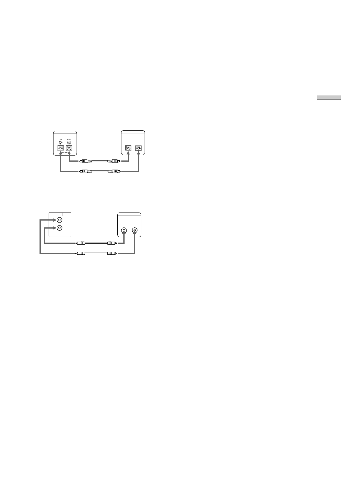
xWhen connecting with digital components
(CD player, DAT recorder, other MD recorders,
mixer with coaxial digital input/output jacks or
optical digital input/output connector.)
When this recorder is connected with a CD player,
MD recorder, or DAT recorder, digital recording can
be performed. Use an optical digital connecting
cable (POC-15A) or a coaxial digital connecting cable
(VMC-10) that can be purchased separately.
• When using an optical digital connecting cable
Take the caps off the connectors and insert the cable
plugs securely.
MD recorder Digital component
DIGITAL
DIGITAL
OPTICAL
OUTIN
Ç
Ç
ç : Flow of signal
• When the coaxial digital cable is used
Getting Started
MD recorder Digital component
DIGITAL
IN
OUT
COAXIAL
DIGITAL
COAXIAL
Ç
Ç
ç : Flow of signal
z A sampling rate converter is mounted in this recorder
All digital input signals are converted to the
sampling frequency (44.1 kHz) of an MD recorder
for recording.
Therefore, this allows you to record sources such as
32 or 48 kHz DAT or satellite broadcasts, as well as
CDs and MDs.
3 Connect the power cord.
OUTIN
17
Page 18
Recording on
Recording on an MD
MDs
This chapter explains the various ways to
record to an MD , as well as how to mark
track numbers and perform synchrorecording with other components.
If the MD has recorded material on it, the recorder will
automatically start recording from the end of the recorded
portion.
POWER
1 Turn on the mixer and program source.
2 Select the source on the mixer.
3 Press POWER to turn on the recorder.
4 Insert a recordable MD.
5 Use INPUT to select the position that corresponds to
INPUT
the input jacks (connector) connected to the
program source.
If the source is connected Display to be selected
to the connector or jacks
DIGITAL OPTICAL connector OPTICAL
DIGITAL COAXIAL jacks COAX
ANALOG (UNBAL) jacks ANALOG
LEVEL / DISPLAY / CHAR TIME
AMS
6 If necessary, locate the point on the MD to start
recording from.
If you want to record on a new MD or start recording
from the end of the recorded portion, go to step 7.
• To record over from the beginning of an existing
MD track
Turn AMS (or press ./> repeatedly) until the
number of the track to be recorded over appears.
• To record over from the middle of an MD track
Turn AMS (or press ./> repeatedly) until the
number of the track to be recorded over appears,
then press 7 to start playback. Press 7 again at
the point you want to start recording from.
7 Press z
The recorder changes to recording pause.
8 If necessary, adjust the recording level.
For details, see “Adjusting the Recording Level” on
page 21.
9 Press 7
Recording starts.
10 Start playing the program source.
18
Page 19
Operations you may want to do during recording
To Press
Stop recording x
Pause recording 7
Resume recording after 7
Eject the MD after stopping recording A
Changing display during recording
Press LEVEL/DISPLAY/CHAR (DISPLAY) repeatedly.
For the contents of display, see “Using the Display
Window” on page 12.
When you pause recording
The track number increases by one. For example, if you
pause recording while recording track 4, the track number
will be 5 when you resume recording.
To prevent accidental erasure of the recorded
material
To make it impossible to record on an MD, slide the
record-protect tab in the direction of the arrow (see
illustration below) to open the slot. To enable recording,
close the slot.
Record-protect tab
Slide in the direction
of arrow
z You can play the tracks you have just recorded
Press 7 or AMS immediately after stopping
recording.
The recorder starts to play from the first track of the
material just recorded.
z You can play from the first track of the MD after recording
1 Press x again after stopping recording.
2 Press 7
The recorder starts to play from the first track of the
MD.
Notes
• You can’t record over existing material when Shuffle
Play (page 32), Program Play (page 33), or Multi-access
Play (page 34) has been selected. “Impossible” appears
in the display at this time.
Notes on Recording
When “ Protected” is displayed
The MD is record-protected. To record on the MD, slide
the tab to close the slot (see “To prevent accidental erasure
of the recorded material” on page 19).
When the record-protect slot is closed and recording is
possible, “Protected” may be displayed and recording may
not be possible. In this case, press z (record) again to
enable recording.
When “Din Unlock” flashes
• The digital component selected with the INPUT selector
is not connected correctly. Connect the component
correctly.
• The selected digital component is not turned on. Turn
on the component.
Marking track numbers depends on the program
source to be recorded.
• When the CD or MD is a program source and they are
recorded through the digital input connector, track
numbers are marked similarly with the CD or MD as the
program source. However, only one track number may
be marked on the recorded portion as below.
- A portion recorded by repeating the same track of the
same disc (by one track repeat)
- A portion recorded by continuing the same track
number of a different disc
When the MD is the program source, a number for a
track of 4 seconds or less may not be marked.
• If the sampling frequency of the input connector changes
when the DAT tape is a program source and it is
recorded through the digital input connector, track
numbers are changed automatically.
When TOC indicator flashes
Do not turn off the recorder, disconnect the AC power, or
move the recorder when recording on the MD because the
recording will be lost. If you turn off the recorder or
disconnect the AC power immediately after recording, the
recording will be lost.
When PLAY MODE is “PROGRAM,” “SHUFFLE,” or
“M.ACCESS” (pages 32, 33, 34)
PLAY MODE changes automatically to “CONTINUE” and
recording pauses.
When ”Cannot Copy” flashes
The mini-disc recorder conforms to the Serial Copy
Management System. MDs recorded through the digital
input connector cannot be copied to other MDs through
the digital output connector (page 61).
Recording on MDs
19
Page 20
MENU / NO
YES
AMS
The digital output connectors of the mini-disk
recorder output the signal input from the digital
input connectors as it is during recording or
recording pause.
Use an input monitor function (page 21) when only a builtin sampling rate converter is used.
Recording on MDs
Recording for long times
In addition to normal stereo recording, this recorder has
two long time recording modes: LP2 and LP4. When
recording in LP2 stereo mode, you can record 2 times the
normal recordable time, and in LP4 Stereo mode, you can
record 4 times the normal recordable time. In addition, the
recordable time for monaural recording is approximately
double the stereo recording time.
Note
MDs recorded in MD LP (LP2 or LP4 Stereo) mode cannot
be played back on a recorder that does not support MD LP
mode. In addition, you cannot perform S.F Edit for MDs
recorded in MD LP mode.
1 Do steps 1 to 5 of “Recording on an MD” on page
18.
2 Press MENU/NO twice.
“Set Up Menu” is displayed.
3 Turn AMS (or press ./> repeatedly) to display
“Rec Mode” and press AMS.
4 Turn AMS to select record mode and press AMS or
YES.
To record in Display to be selected
Stereo Stereo
Monaural Mono
LP2 stereo Long 2
LP4 stereo Long 4
“LP2,” “LP4,” or “MONO” lights
up on the lower left of the display
window by the selected mode.
5 Press MENU/NO.
6 Do steps 6 to 10 of “Recording on an MD” on page
18.
20
Hidden “LP:” is recorded at the beginning of
tracks during MD LP recording.
This is a confirmation stamp indicating no play when play
is performed by the non-MD LP component. The stamp is
not displayed by playable MD LP components, but is
displayed when play is performed by the non-MD LP
component.
If the name of the MD LP-recorded track is copied as the
name of the MONO or STEREO recorded track, “LP:” is
displayed (page 48).
Page 21
Adjusting the Recording
I
l
Level
You can adjust the recording level for both analog and
digital recording.
LEVEL / DISPLAY / CHARMENU / NO YES
AMS
1 Do steps 1 to 7 of “Recording on an MD” on page
18.
2 Play the portion of the program source with the
strongest output.
3 Press LEVEL/DISPLAY/CHR (or DISPLAY) repeatedly
until the level of the input signal appears.
4 Turn AMS (or press LEVEL +/_ repeatedly) to adjust
the recording level.
Adjust the recording level so that two rightmost
indicators on the peak level meters do not light up
when the play level is the highest level.
nput Leve
Coax -5.0dB
Avoid turning on
these indicators
5 Stop playing the program source.
6 To start recording, continue from step 9 of
“Recording on an MD” on page 18.
z The balance of the left and right recording levels can be
adjusted in Setup Menu during analog input
1 Press MENU/NO twice.
“Setup Menu” appears in the display.
2 Turn AMS (or press ./> repeatedly) to select
“Anlg In L/R” then press AMS or YES.
3 Turn AMS (or press ./>) to adjust the balance.
When you turn AMS clockwise, the level on the L side
decreases relatively for R. When you turn it
counterclockwise, the level on the R side decreases for L.
Press AMS or YES.
4 Press MENU/NO.
z
Turn ANALOG INPUT LEVEL at the rear of the recorder to
adjust the recording level of analog input.
ANALOG INPUT LEVEL
A range of _ ∞ ~ +15 dB can be adjusted by ANALOG
INPUT LEVEL. This adjustment can be used when the
analog output level of connected components is too low or
too high.
Normally use the range in the initialized center position
(0dB).
z
You can use a peak hold function
The state of the peak level meter when the level of the
input/output signal is the highest can be stopped for
display until the signal exceeding the level is input.
1 Press MENU/NO twice during stop or play.
2 Turn AMS (or press ./> repeatedly) until “Peak
Hold” appears, then press AMS or YES.
3 Turn AMS (or press ./> repeatedly) to select
“On,” then press AMS or YES.
4 Press MENU/NO.
To cancel the peak hold function, select “Off” at step 3.
Recording on MDs
z You can adjust the recording level using the remote Z
During recording or recording pause, pr ess LEVEL +/_
repeatedly.
z You can use Setup Menu to adjust the recording level
1 During recording or recording pause, press MENU/NO
twice.
“Setup Menu” appears in the display.
2 Turn AMS (or press ./> repeatedly) to select
“Input Level Coax,” “Input Level Opt,” or “Input Level
Anlg,” then press AMS or YES.
3 Turn AMS (or press ./> repeatedly) to adjust the
recording level, then press AMS or YES.
4 Press MENU/NO.
Note
The volume can only be increased up to +12 dB (for analog
recording) or +18.0 dB (for digital recording). Therefore, if
the output level of the connected component is low, it may
not be possible to set the recording level to maximum.
21
Page 22

Recording Tips
Erasing blank portions automatically
(Smart Space/Auto Cut)
Monitoring the input signal (Input
Recording on MDs
Monitor)
You can monitor the selected input signal even when you
aren’t recording it.
1 Press Z to eject the MD.
2 Use INPUT to select the program source to be
monitored.
3 Press z.
• When “ANALOG” is selected by INPUT
• When “OPTICAL” or “COAXIAL” is selected by
Stopping the input monitor
Press x.
MENU / NO YESINPUT
Z EJECT
The analog signal input from the ANALOG IN jacks is
output to the DIGITAL OUT connector after A/D
conversion, and then to the ANALOG OUT jacks and
PHONES jack after D/A conversion.
“AD - DA” appears in the display during this time.
INPUT
The digital signal input from the DIGITAL IN
connector is output to the DIGITAL OUT connector
after passing through the sampling rate converter, and
then to the ANALOG OUT jacks and PHONES jack
after D/A conversion.
“- DA” appears in the display during this time.
AMS
The recorder can be set to automatically erase any blanks
that are produced when the signal is interrupted during
recording. The function which activates (Smart Space or
Auto Cut) depends on the length of the interruption, as
described below.
Smart Space
If the signal is interrupted for less than 30 seconds, Smart
Space replaces the blank portion with a blank space of
about 3 seconds, then continues the recording. “Smart
Space” appears in the display during this time.
Auto Cut
If the signal is interrupted for about 30 seconds, Auto Cut
replaces the blank portion with a blank space of about 3
seconds, then pauses the recording. “Auto Cut” appears
in the display during this time.
Do the procedure below to turn Smart Space and Auto Cut
on or off.
1 While the recorder is stopped, press MENU/NO
twice.
“Setup Menu” appears in the display.
2 Turn AMS (or press ./> repeatedly) until
“Smart Space” appears, then press AMS or YES.
3 Turn AMS (or press ./> repeatedly) and select
“On” for automatic operation and “Off” for no
automatic operation, then press AMS or YES.
4 Press MENU/NO.
Note
• If you start recording with no signal input, Smart Space
and Auto Cut will not operate until the signal is input
regardless of the setting.
• Smart Space does not affect the order of the track
numbers being recorded, even if the blank space occurs
in the middle of a track.
• Auto Cut is automatically turned on or off in tandem
with Smart Space.
• If you turn off the recorder or disconnect the AC power
cord, the recorder will store the last setting and recall it
the next time you turn on the recorder.
22
Page 23

Marking Track Numbers
While Recording
(Track Marking)
You can mark track numbers either manually or
automatically while recording. By marking track numbers
at specific points, you can quickly locate the points later or
edit the MD easily.
To set the level of input signals for Automatic
Track Marking of “Level Sync”
The recorder marks a track number whenever the input of
a signal at the set level or below continues for at least 1.5
seconds and a signal at the set level or above is also input.
1 While the recorder is stopped, press MENU/NO
twice.
“Setup Menu” appears in the display.
2 Turn AMS (or press ./> repeatedly) until “Tr
Mark Level” appears, then press AMS or YES.
MENU/NO YES
AMS
Marking track numbers manually (Manual
Track Marking)
Press z at the point where you want to add a track
number while recording.
Marking track numbers automatically
(Automatic Track Marking)
When recording from a CD player or MD recorder
connected to the DIGITAL IN connector, the recorder
marks track numbers in the same sequence as the source.
When recording from other sources connected to the
DIGITAL IN connector or a source connected to the
ANALOG IN jacks, do the procedure below to mark track
numbers automatically. However, if you hear much noise
from the sources of tapes or radios, the recorder cannot
mark track numbers.
3 Turn AMS (or press ./> repeatedly) to select
the level at any value from a range of _72 dB, _68
dB, _60 dB, _54 dB, and _48 dB, then press AMS or
YES.
4 Press MENU/NO.
To set the interval time of Automatic Track
Marking
The recorder marks a track number at intervals at the set
time.
1 While the recorder is stopped, press MENU/NO
twice.
“Setup Menu” appears in the display.
2 Turn AMS (or press ./> repeatedly) until
“Interval” appears, then press AMS or YES.
3 Turn AMS (or press ./> repeatedly) to select
the time at any value from a range of 1 minute to
10 minutes, then press AMS or YES.
Note
When the track number of program sources (CD or MD)
changes, a track number changes automatically, or you
want to change the track number by z (REC), the recorder
marks a track number at the interval of the fixed time from
the beginning of the changed track number.
Recording on MDs
1 While the recorder is stopped, press MENU/NO
twice.
“Setup Menu” appears in the display.
2 Turn AMS (or press ./> repeatedly) until “Track
Mark” appears, then press AMS or YES.
3 Turn AMS (or press ./> repeatedly) to select
the setting, then press AMS or YES.
Automatic tracking marking Select
Turned on at input level Level Sync
Turned on at the interval Interval
of the fixed time
Turned of f Off
4 Press MENU/NO.
z
Additional information on Automatic Track Marking
• When recording from a CD player or MD recorder
connected to the DIGITAL IN connector, the entire
material may be recorded as a single track in the
following cases:
- When you consecutively record the same track two or
more times using single-track repeat play.
- When you consecutively record two or more tracks
with the same track number but from different CDs or
MDs.
- When you record tracks from certain CD or multi-disc
players.
In either case, divide tracks after recording (page 45).
• If the source is an MD, a track number may not be
marked for tracks less than 4 seconds long (during
stereo, LP2 stereo, or monaural recording) or less than 8
seconds (during LP4 stereo recording).
23
Page 24

• When recording from a component connected to the
AMS
ANALOG IN jacks with “Track Mark Off” selected or
when recording from a DAT recorder or DBS tuner
connected to the DIGITAL IN connector, the entire
material may be recorded as a single track.
• When recording from a DAT recorder or DBS tuner
connected to the DIGITAL IN connector, the recorder
will mark a track number whenever the sampling
frequency of the input signal changes, regardless of the
track marking parameter setting .
z
You can mark track numbers even after recording has finished
See “Dividing Tracks” on page 45.
Recording on MDs
Note
If you turn off the recorder or disconnect the AC power
cord, the recorder will store the last settings of “Track
Mark” and recall them the next time you turn on the
recorder.
Starting Recording With 6
Seconds of Prestored Audio
Data
(Time Machine Recording)
Whenever the recorder is in recording pause, the
recorder’s buffer memory continuously stores the latest 6
seconds worth of audio data. When you press AMS (or
T.REC), the recording then starts with the data in the
buffer memory. Time Machine Recording thus allows you
to avoid missing the beginning of material recorded live
from an FM or satellite broadcast.
1 Do steps 1 to 7 of “Recording on an MD” on page
18.
The recorder changes to recording pause.
2 Start playing the program source.
3 Press AMS (or T.REC) at the point where you want
to start recording.
Recording starts with the 6 seconds of prestored data in
the buffer memory, then continues recording via the
buffer memory thereafter.
To stop Time Machine Recording
Press x.
Note
The storage of data in the buffer memory starts from the
moment the recorder changes to recording pause. Thus, if
you start recording less than 6 seconds worth of data will
be recorded from the buffer memory.
24
Page 25

Synchro-recording With the
Synchro-recording With a
Audio Component of Your
Choice
(
Music Synchro-recording
The Music Synchro-recording allows you to automatically
synchronize recording on the MD recorder with the
playing of the selected ogram sour ce. The Track
Marking function, however, will differ according to the
program source. For details, see “Marking Track Numbers
While Recording” on page 23.
M.ACCESS
CONTINUE SHUFFLE PROGRAM
12345
678910
11 12 13 14 15
16 17 18 19 20
21 22 23 24 25
>25
NAME CHAR
NUM
MUSIC SYNC
RM-DR1J
1 Do steps 1 to 6 of “Recording on an MD” on page
18.
2 Press MUSIC SYNC.
The recorder changes to recording pause.
3 Start playing the program source.
Recording starts automatically.
To stop Music Synchro-recording
Press x.
Note
During Music Synchro-recording, Smart Space and Auto
Cut (page 22) will operate regardless of their setting.
) Z
Sony CD Player (CD
Synchro-recording) Z
When the recorder is connected to a Sony CD player or HiFi component system, you can easily copy the contents of
CDs to the MD using the recorder’s remote. As the same
remote operates both the MD recorder and the CD player
or CD player section of the component system, make sure
to place the MD recorder and the CD player as close
together as possible.
Note
• Some CD players do not allow you to synchronize CD
recording with the remote of the recorder. In this case,
use music synchro-recording on this page to synchronize
recording on the CD player and recorder.
• To operate the recorder and CD player, unplug from the
jacks of the recorder and remote and use the remote as
the wireless remote (page 16).
M.ACCESS
CONTINUE SHUFFLE PROGRAM
12345
678910
11 12 13 14 15
16 17 18 19 20
21 22 23 24 25
>25
NAME CHAR
CD SYNC
START
CD SYNC
STOP
CD PLAYER
/
1 Turn on the mixer (amplifier) and the CD player, and
select CD on the mixer (amplifier).
2 Do steps 3 to 6 of “Recording on an MD” on page
18.
NUM
CD SYNC
STANDBY
RM-DR1J
Recording on MDs
3 Insert a CD into the CD player and select the
playback mode (Shuffle Play, Program Play, etc.) on
the CD player.
4 Press CD-SYNC STANDBY.
The CD player changes to play standby and the MD
recorder changes to recording standby.
5 Press CD-SYNC START.
The recorder starts recording and the CD player starts
playing.
The track number and elapsed recording time of the
track appear in the display.
If the CD player doesn’t start playing
Some CD players may not respond when you press
CD-CYNC START. Press X on the CD player’s remote
instead to start playing on the CD player.
25
Page 26

Operations you may want to do during CD
Synchro-recording
To Press
Stop recording CD-SYNCHRO STOP
Pause recording CD-SYNCHRO STANDBY
Locate the next track to CD PLAYER ./>
be recorded during
recording pause
Resume recording CD-SYNCHRO START
after pausing
Check the remaining TIME of the recorder
recordable time on the MD
You can use the remote of the CD player during CD Synchro-
z
Recording on MDs
recording
Press To change the And change the
H Recording Play
x Recording pause Stop
X Recording pause Pause
You can change CDs during CD Synchro-recording
z
1 Press x on the CD player’s remote.
2 Change the CD.
3 Press H on the CD player’s remote.
Recording resumes.
recorder to CD player to
Notes
• When performing CD Synchro-recording with a CD
player with a mode selector, be sure to set the selector to
CD1.
• When you record tracks from certain CD or multi-disc
players, the entire material may be recorded as a single
track.
26
Page 27

Playing MDs
Playing an MD
This chapter explains the various ways to
play MDs.
POWER AMS
1 Turn on the mixer.
2 Adjust the fader or level of the connected channel
of the mixer.
3 Press POWER to turn on the recorder.
4 Insert an MD.
5 If necessary, turn AMS (or press ./>
repeatedly) to locate the track you want to start
playing from.
If you want to play from the first track, go to step 6.
6 Press 7.
The recorder starts playing.
Operations you may want to do during play
To Press or turn
Stop play x
Pause play 7
Resume play after pausing 7
Locate a succeeding track AMS clockwise (or press >
repeatedly)
Locate the beginning of AMS counterclockwise (or
the current track or press . repeatedly)
a preceding track
Eject the MD After stopping play A
z To play the MD on which LP2, LP4 stereo recording or MONO
recording has been performed
By pressing 7 in step 6 above, “LP2,” “LP4,” or
“MONO” lights up depending on the mode recorded
on the lower left of the display window.
z To use headphones
Connect them to PHONES jack. Turn PHONE LEVEL
to adjust the volume.
27
Page 28

z You can adjust the analog signal output level.
1 While the recorder is playing, press LEVEL/DISPLAY/
CHA (or DISPLAY) repeatedly until the line output
adjustment display appears.
2 Turn AMS (or press LEVEL +/_ repeatedly) to adjust
the output signal level.
z You can use Setup Menu to adjust the analog output level
1 Press MENU/NO twice.
“Setup Menu” appears in the display.
2 Turn AMS (or press ./> repeatedly) to select
“Output Level,” then press AMS or YES.
3 Turn AMS (or press ./> repeatedly) to adjust the
output level, press AMS or YES.
4 Press MENU/NO.
z You can make EJECT not function during play or pause to
avoid ejecting the MD by mistake.
1 Press MENU/NO twice during stop.
“Setup Menu” appears in the display.
Playing MDs
2 Turn AMS (or press ./> repeatedly) to select
“Play Pause,” then press AMS or YES.
3 Turn AMS (or press ./> repeatedly) to select “Z
Disable,” then press AMS or YES.
4 Press MENU/NO.
To function EJECT, select “Z Enable” in step 3.
28
Page 29

Playing a Specific Track
Playing a track by entering the track
number Z
While the recorder is playing, pause or stopped, use the
procedure below to quickly play any track.
M.ACCESS
>25
CONTINUE SHUFFLE PROGRAM
12345
678910
11 12 13 14 15
16 17 18 19 20
21 22 23 24 25
>
25
NAME CHAR
NUM
RM-DR1J
AMS
NUMBER BUTTONS
M.SCAN
/ (AMS)
Locating a track with AMS*
To go to Do the following:
The next or a succeeding Turn AMS clockwise (or press
track during play > repeatedly).
A preceding track Turn AMS counterclockwise
during play (or press . repeatedly).
The beginning of the Turn AMS counterclockwise
current track during play (or press . once).
A specific track while the 1 Turn AMS (or press ./
recorder is stopped > repeatedly) until the
track number appears in the
display.
2 Press AMS or 7.
* Automatic Music Sensor
z To locate the last track of the MD quickly
While the recorder is stopped, turn AMS
counterclockwise (or press . once).
Press the number button(s) to enter the track number of
the track you want to play.
To enter a track number over 26
1 Press >25.
See the examples below for the number of presses.
2 Enter the corresponding digits.
To enter 0, press 10 instead.
Examples:
• To play track number 30, press >25, then 3 and 10.
• To play track number 108, press >25 twice, then 1, 10,
and 8.
z If you enter a track number while the recorder is paused
The recorder will be paused at the beginning of the
track.
Locating a point by monitoring the
beginning of each track Z (Music Scan)
If M.SCAN is pressed during stop, the beginning of each
track is played sequentially only at the set fix time.
Press H for the track you want to monitor.
z You can adjust the play time for the beginning of a track by
MUSIC SCAN
1 Press MENU/NO twice.
“Setup Menu” appears in the display.
2 Turn AMS (or press ./> repeatedly) to select
“Music Scan,” then press AMS or YES.
3 Turn AMS until the desired time of 6 to 20 seconds
appears in the display, then press AMS or YES.
4 Press MENU/NO.
Playing MDs
z If you locate a track while the recorder is stopped or paused
The recorder will still be stopped or paused at the
beginning of the located track.
29
Page 30

Reserving the next track during play
/
(Next Track Play)
A desired one track can be reserved for the next track by
turning “Next Tr Play (Next Track Play)” of “Setup Menu”
to “On.”
1 Press MENU/NO twice during stop.
“Setup Menu” appears in the display.
2 Turn AMS (or press ./> repeatedly) to select
“Next Tr Play,” then press AMS or YES.
3 Turn AMS to select “On,” then press AMS or YES.
4 Press MENU/NO.
5 Press 7.
6 Press DISPLAY/LEVEL/CHAR until the reservation of
the next track to play appears.
Playing MDs
7 Turn AMS (or press ./> repeatedly) to select a
track number to be reserved in the flashing track
number display, then press AMS. After reservation,
the flashing of the track number stops.
8 When the play of the track number reserved in step
7 starts, the flashing of the track number display
starts again. Repeat the operation in step 7 to
reserve the next track number.
NextNo Name
6 3m28s
Tr
Locating a Particular Point
in a Track
You can locate a particular point in a track during play or
play pause.
Locating a point while monitoring the
sound (Search)
Press down m/M during play.
You will hear intermittent playback as the disc goes
forward or in reverse.
When you reach the point you want, release the button.
Notes
• If the disc reaches the end while you’re pressing M, the
recorder stops.
• Tracks that are only a few seconds long may be too short
for monitoring. For such tracks, play the MD at normal
speed.
Notes
• Tracks cannot be reserved when PLAY MODE is
PROGRAM, SHUFFLE, or M.ACCESS.
• The reserved track cannot be located by AMS.
If AMS is turned, the reserved track is canceled, a mode
is set to select a new reserved track.
Locating a point by observing the time
indication (High speed search)
Press down m/M during play pause.
You won’t hear playback.
When you reach the point you want, release the button,
then press 7.
z When “- Over -“ appears in the display
The disc has reached the end while you’re pressing
M. Turn AMS counterclockwise (or press .) or
press m to go back.
30
Page 31

Playing Tracks Repeatedly
(Repeat Play)
You can play an entire MD repeatedly. This function can
be used with Shuffle Play to repeat all the tracks in random
order, or with Program Play to repeat all the tracks in the
program. You can also repeat a specific track or portion
within a track.
Repeat play cannot be performed during Multi-access play
(page 34).
Repeating the current track
(Repeat 1 Play) Z
The current track is repeated.
Press REPEAT until “Repeat 1” appears at the display
window.
M.ACCESS
A -B
CONTINUE SHUFFLE PROGRAM
12345
678910
11 12 13 14 15
16 17 18 19 20
21 22 23 24 25
>
25
NAME CHAR
NUM
MENU / NO
YES
REPEATE
AMS
Note
If you turn off the recorder or disconnect the AC power
cord, the recorder will store the last setting of the repeat
play (“Repeat All” or “Repeat 1”) and recall it the next
time you turn on the recorder. However, A - B Repeat is
canceled.
Repeating all the tracks on the MD (Repeat
All Play) Z
All tracks are repeated.
Press REPEAT until REPEAT lights up at the display
window.
When you play an MD, Repeat 1 Play starts.
To resume normal play
Press REPEAT until “REPEAT 1” at the display window
turns off.
z You can also set Repeat 1 Play in the Setup Menu of the
Playing MDs
recorder.
RM-DR1J
1 Press MENU/NO twice.
“Setup Menu” appears in the display.
2 Turn AMS to select “Repeat Mode,” then press AMS or
YES.
3 Turn AMS to select “Repeat 1,” then press AMS or YES.
4 Press MENU/NO.
When you play an MD, the recorder repeats the tracks as
follows:
When the play mode is The recorder repeats
Normal play (page 27) All the tracks in sequence
Shuffle play (page 32) All the tracks in random order
Program Play (page 33) All the tracks in the program
in sequence
To resume normal play
Press REPEAT until “REPEAT” at the display window
turns off.
z You can also set Repeat All Play in the Setup Menu of the
recorder.
1 Press MENU/NO twice.
“Setup Menu” appears in the display.
2 Turn AMS to select “Repeat Mode,” then press AMS or
YES.
3 Turn AMS to select “Repeat ALL,” then press AMS or
YES.
4 Press MENU/NO.
31
Page 32

Repeating a specitic portion within a track
(Repeat A-B Play) Z
You can specify a portion within a track to play repeatedly.
This is convenient to study language or memorize words.
Note that the portion that you specity must be within the
bourdaries of a single track.
1 While the recorder is playing, press A ↔ B at the
starting point (point A) of the portion to be played
repeatedly.
“REPEAT A-B” lights up.
Playing Tracks in Random
Order (Shuffle Play) Z
When you select Shuffle Play, the recorder plays all the
tracks on the MD in random order.
M.ACCESS
MENU / NO
YES
SHUFFLE
CONTINUE SHUFFLE PROGRAM
12345
678910
11 12 13 14 15
16 17 18 19 20
21 22 23 24 25
>
25
NAME CHAR
NUM
/
2 Continue playing the track or use M to locate the
ending point (point B) of the portion to be played
Playing MDs
repeatedly, then press A ↔ B again.
The specified portion repeats.
To stop Repeat A-B Play
Press REPEAT or x.
To set a new starting point and ending point
during Repeat A-B Play
Specify the starting point and ending point by the same
operation.
z You can also set A-B Repeat in the Setup Menu of the
recorder.
1 Press MENU/NO during play until “Setup Menu”
appears in the display.
2 Turn AMS until “Repeat Mode” appears at the display
window, then press AMS.
3 Turn AMS until “A-B Repeat,” then press AMS.
The display window returns to the track number and
time display (normal display) during play, then
“REPEAT A-B” lights up and “A-B” flashes.
4 Press AMS at the starting point (point A) of a portion to
be played repeatedly.
5 Continue playing the track or use M to locate the
ending point (point B) of the portion to be played
repeatedly, then press AMS again.
AMS
1 Press SHUFFLE while the recorder is stopped.
“SHUFFLE” lights up at the display window.
2 Press H.
Shuffle Play starts.
To resume normal play from Shuffle Play
Press CONTINUE while the recorder is stopped.
“SHUFFLE” at the display window turns off.
z You can locate tracks during Shuffle Play
Turn AMS (or press ./>). To locate the next
track or a later track to be played, turn AMS clockwise
(or press ./>). To locate the beginning of the
current track, turn AMS counterclockwise (or press
.). Note that you can’t locate and play the tracks
that have already been played once.
z You can also set Shuffle Play in the Setup Menu of the
recorder.
1 Press MENU/NO twice.
“Setup Menu” appears in the display.
2 Turn AMS to select “Play Mode,” then press AMS or
YES.
3 Turn AMS to select “Shuffle,” then press AMS or YES.
4 Press MENU/NO.
RM-DR1J
Note
A-B Repeat does not work during Shuffle Play or Multiaccess Play.
32
Page 33

Creating Your Own Program
g
y
(Program Play)
You can pick out the tracks that you like and specify the
playback order in a program containing up to 25 tracks.
MENU / NO
MENU / NO
AMSCLEAR
YES
/
NUMBER BUTTONS
Programming the tracks
DISPLAY
CONTINUE
PROGRAM
CLEAR
M.ACCESS
CONTINUE SHUFFLE PROGRAM
12345
678910
11 12 13 14 15
16 17 18 19 20
21 22 23 24 25
>
25
NAME CHAR
>25
/
/
NUM
RM-DR1J
6 Turn AMS (or press ./> repeatedly) to select
“Play Mode,” then press AMS or YES.
7 Turn AMS (or press ./> repeatedly) to select
“Program,” then press AMS or YES (or press
PROGRAM after step 5 for the remote).
“PROGRAM” lights up at the display window.
8 Press 7 ( H ).
Program replay starts.
To stop Program Play
Press x.
To resume normal play
While the recorder is stopped, press CONTINUE in the
remote. “PROGRAM” at the display window turns off.
Playing MDs
1 While the recorder is stopped, press MENU/NO
twice.
“Setup Menu” appears in the display.
2 Turn AMS (or press ./> repeatedly) until
“Program?” of “Setup Menu” appears, then press
AMS or YES.
3 Turn AMS (or press ./> repeatedly) until the
track number you want to add to the program
appears, then press AMS (or use the number
button(s) to enter the track directly).
Programmed track number
and track order
/6 8 10 0/
3S 12m27s
Number of
rammed tracks
pro
If you entered the wrong track number
Press m repeatedly until the wrong track number
flashes, then do step 3 above again or press CLEAR to
erase the track number.
To enter a track number over 26 Z
Use >25. For details, see page 29.
Total time of
programmed pla
z The program remains even after Program Play ends or is
stopped
Press 7 to play from the beginning of the program
again. If the play is stopped, the program will not be
lost.
Notes:
• If the MD is ejected, the program will be lost.
• The display shows “— m — s” when the total playing
time of the program exceeds 255 minutes.
• “ProgramFull” appears when you try to program 26 th
track.
• The set program will be lost when you try record or edit
operation.
Checking the order of tracks in the
program
While the recorder is stopped and “PROGRAM” lights
up, press LEVEL/DISPLAY/CHAR (or DISPLAY)
repeatedly.
The first several tracks in the program appear in the
display.
z To see the rest of the program
After the first several tracks in the program appear by
the above procedure, turn AMS clockwise (or press
repeatedly).
4 Repeat step 3 to enter other tracks.
The entered track is added to the location where the
“0” flashes.
Each time you enter a track, the total program time
appears in the display.
5 Press YES.
“Complete!” appears and the program is completed.
33
Page 34

Changing the contents of the program
3m28s
No 1-- 6
Programmed track order Programmed track number
Time of playing the programmed track
Tr
While the recorder is stopped and “PROGRAM” lights up,
do steps 1 and 2 of “Programming the tracks” on page 33,
followed by one of the procedures below.
To Do the following:
Erase a track Press m/M repeatedly until the
Erase all tracks Press CLEAR repeatedly until all the
Add a track at the Press m repeatedly until “0” flashes
beginning of the before the first track number, then do
program steps 3 to 5 of “Programming the
Add a track in the Press m/M repeatedly until the
middle of the track number which will precede the
program new track flashes. Press AMS to
Playing MDs
Add a track to the Press M repeatedly until “0” flashes
end of the program after the last track number, then do
Replace a track Press m/M repeatedly until the
number of the unwanted track
flashes, then press CLEAR.
track numbers disappear.
tracks” on page 33.
display flashing “0,” then do steps 3
to 5 of “Programming the tracks” on
page 33.
steps 3 to 5 of “Programming the
tracks” on page 33.
number of the track to be changed
flashes, then do steps 3 to 5 of
“Programming the tracks” on page
33.
Storing the Located Track to
Start Play Instantaneously
(Multi-access Play)
The begining of track is prestored in memory and play
starts instantaneously when the track is selected.
Up to 10 tracks can be stored in memory.
The function below cannot work in Multi-access.
Multi-access is based on single play. This function is used
to instantaneously play the track specified by the Number
key on the remote (track selected by AMS of the recorder).
Therefore, Record, Variable speed play, m/M
(backward/forward), Repeat Play, Auto Pause, Auto Cue,
Mark, and Locate function are invalid.
YES
MENU / NO
M.ACCESS
MENU / NO
AMSCLEAR
YES
/
CONTINUE
NUMBER BUTTONS
CLEAR
Programming access play tracks
M.ACCESS
CONTINUE SHUFFLE PROGRAM
12345
678910
11 12 13 14 15
16 17 18 19 20
21 22 23 24 25
>
25
NAME CHAR
>25
/
/
NUM
RM-DR1J
1 While the recorder is stopped, press MENU/NO
twice.
“Setup Menu” appears in the display.
2 Turn AMS (or press ./> repeatedly) to select
“M.Access?” then press AMS or YES.
The display window displays the access play track in
the program.
No 1-- 0
Tr
3 Turn AMS (or press ./> repeatedly) to select a
track number you want to store, then press AMS or
YES. (Or press the Number buttons to directly enter
the track number.)
34
Page 35

If you entered the wrong track number
Press m repeatedly until the wrong track number
appears and turn AMS (or press ./> ) to enter a
correct track number. Press CLEAR to erase the track
order so that the track order is moved up.
To enter a track number over 26
Use >25. For details, see page 29.
4 Repeat step 3 to store the track you want to access.
5 Press YES.
“Complete!” appears and the track order and track
number to be stored are completed.
6 Turn AMS (or press ./> repeatedly) to select
“Play Mode” of “Setup Menu” then press AMS or
YES.
7 Turn AMS (or press ./> repeatedly) to select
“M.Access” then press AMS or YES. (Press
M.ACCESS after step 5 for the remote.)
“M.Access” and “1” (Single Play) light up and
“Memorizing” (during recording) flashes, then the
normal screen is returned.
Multi-access play Z
Press the Number buttons on the remote you want to play
the track order.
z
To play by the recorder
Turn AMS to select the track order, then press AMS.
To resume normal play
While the recorder is stopped, press CONTINUE on the
remote. “M.Access” and “1” at the display window turn
off.
z
The program is stored until the MD is ejected
If the play is stopped or Play Mode is changed and
“M.Access” turns off, the program is stored. If the
multi-access is selected again, “Memorizing” flashes
and the entered program is stored in memory.
Notes
• If the MD is ejected, the program will be lost.
• “ProgramFull” appears when you try to program 11 th
track.
• The set program will be lost when you try record or edit
operation.
Playing MDs
Memorizing
M.ACCESS
Note
If the MD is inserted when Multi-access Play is selected,
“Memorizing” flashes and track numbers 1 to 10 in the
track order are recorded and programmed automatically.
To stop “Memorizing”
Press x (stop) when “Memorizing” is flashing.
“Memorizing” stops and “Play Mode” returns to normal
play (CONTINUE).
1
Checking the program
1 While the recorder is stopped, press MENU/NO
twice.
“Setup Menu” appears in the display.
2 Turn AMS (or press ./> repeatedly) to select
“M.Access?” then press AMS or YES.
3 Press m/M repeatedly for checking.
4 Press MENU/NO to return normal display.
Changing the contents of the program
Do steps 1 to 2 of “Checking the program” and follow the
procedures below.
To Do the following:
Erase a track Press m/M repeatedly until the
number of the unwanted track
appears, then press CLEAR.
Erase all tracks Press CLEAR repeatedly until all the
track numbers disappear.
Add a track to the Press M repeatedly until the track
end of the program order in which “0” flashes, then do
step 3 of “Programming access play
tracks” on page 34.
If 10 tracks are programmed,
“ProgramFull” appears and no
addition is made.
Replace a track Press m/M repeatedly until the
changed track order appears, then do
step 3 of “Programming access play
tracks” on page 34.
35
Page 36

Setting Play Start Position
MENU / NO
YES
LOCATE
AMS
(MARK)
00f
2 0m00s
Tr
Returning to the Specified
After Play Is Stopped
(Resume Play)
After play is stopped by pressing STOP, you can set play
start position when play starts.
1 While the recorder is stopped, press MENU/NO
Playing MDs
twice.
“Setup Menu” appears in the display.
2 Turn AMS (or press ./> repeatedly) to select
“Resume Mode,” then press AMS or YES.
3 Turn AMS (or press ./> repeatedly) to select
from the following three edit modes:
Resume Off: No resume play is performed.
Resume Play: Play starts from the position of previous
Resume Next: Play starts from the beginning of the
Press AMS or YES.
4 Press MENU/NO.
Note
Resume Play becomes OFF forcibly and does not work
during Shuffle Play or Multi-access Play.
If you use Resume Play again, reset by the above
procedure.
MENU / NO
stop.
next track of the previously stopped
track.
YES
AMS
Point (Locate Play)
You can repeatedly locate the desired setting point.
To mark the desired point (MARK)
The following two ways can be used to determine the
point.
1 Press AMS (MARK) during play.
The play time when AMS is pressed is determined the
specified point. ”MARK” lights up at the display
window.
- MARK 2 4m09s
2 Specify numeric directly for the track number and
play time to set the point.
1 While the recorder is stopped, press MENU/NO
twice.
“Setup Menu” appears in the display.
2 Turn AMS (or press ./> repeatedly) to select
“Direct Mark”, then press AMS or YES.
3 Turn AMS to display the track number to be
located , then turn AMS.
Tr
36
4 Similarly with step 3, set minutes, seconds, and
frames in order to locate a point.
“Complete!” appears and “Mark” lights up at the
display window, then normal display is returned.
You can slide a position for each frame* (f) (1 frame =
1/86 seconds).
* Monaural or LP2 stereo tracks move two frames at
a time, LP4 stereo tracks move four frames at a
time.
To set quickly, press m/M repeatedly in step 4.
Change units advanced when AMS is turned (or
m/M is pressed) to frames, seconds, or minutes.
Page 37

Fine adjusting the marked point
(Rehearsal)
You can fine adjust the determined point while monitoring
the sound of play.
1 While the recorder is stopped, press MENU/NO
twice.
“Setup Menu” appears in the display.
2 Turn AMS (or press ./> repeatedly) to select
“Mark Rehear”, then press AMS or YES.
“-Rehearsal-” flashes and play is repeated for several
seconds from the already determined point.
-Rehearsal 3m43s04f
3 Turn AMS (or press ./> repeatedly) to move
the location of a track.
You can slide a position for each frame* (f) (1 frame =
1/86 seconds).
* Moraural or LP2 stereo tracks move two frames at a
time, LP4 stereo tracks move four frames at a time.
To set quickly, press m/M repeatedly in step 4.
Change units advanced when AMS is turned (or ./
> is pressed) to frames, seconds, or minutes.
Pausing After Each Track
(Auto Pause)
You can set the MD recorder so that it pauses
automatically at the beginning of the next track after play
back of each track. This is convenient to record one track
only or several uncontinuous tracks.
M.ACCESS
CONTINUE SHUFFLE PROGRAM
12345
AUTO CUE
A.CUE
A.PAUSE
Press AUTO CUE repeatedly until “A.PAUSE” appears at
the display window. (Or press A.CUE/A.PAUSE.)
678910
11 12 13 14 15
16 17 18 19 20
21 22 23 24 25
>
25
NAME CHAR
NUM
RM-DR1J
Playing MDs
4 After the point is determined, press AMS or YES.
“Complete” appears and normal display is returned.
Notes
• If the point (MARK) is not determined, “Mark Rehear”
of “Setup Menu” does not appear.
• Adjustment of the point in Rehearsal cannot be moved
over the track.
To locate the marked point
When LOCATE is pressed, play pauses in the determined
marked point. You can start playing again from the same
location.
Notes
• When one of the following operations is performed,
Mark is released. To play Locate, set Mark again.
· Eject the disc.
· Perform Edit Menu.
· Record.
• During the programmed play, if the LOCATE is pressed
though the Track in which the marked point is not
included to the playing program, “No Program” is
displayed.
• Locate does not function during shuffle Play and Multiaccess Play.
To stop Auto Pause
Press AUTO CUE repeatedly until “A.PAUSE” at the
display window disappears. (Or press A.CUE/A.PAUSE.)
37
Page 38

Making Track Play Start
Soon (Auto Cue)
Auto Pause and Auto Cue
Portion of track
Portion of sound
You can skip the portion from the beginning of a track to
actual sound playing start. This is convenient to add a
sound during video editing (postrecording).
Playing MDs
1 Press AUTO CUE repeatedly until “A.CUE” lights up
at the display window. (Or press A.CUE/A.PAUSE.)
2 When you turn AMS to select a track number in
which you want to start playing soon, then press
AMS (or press Number buttons), the recorder
searches the first portion where the sound of the
track is made and play pauses.
3 When 7 is pressed, play starts instantaneously.
To stop Auto Cue
Press AUTO CUE until “A.CUE” at the display window
disappears. (Or press A.CUE/A.PAUSE.)
AUTO CUE
A.CUE
A.PAUSE
M.ACCESS
CONTINUE SHUFFLE PROGRAM
12345
678910
11 12 13 14 15
16 17 18 19 20
21 22 23 24 25
>
25
NAME CHAR
NUM
Auto Pause
Auto Cue
First track
PP P
PP P
Second track Third track
z You can select the level (threshold level) of a sound in the
Auto Cue position
The recorder finds the first point to which a sound of
RM-DR1J
_72dB or more is output from the beginning of a track and
play pauses.
You can select the level of a sound at the pause point
among 5 levels (_72 dB, _68 dB, _60 dB, _54 dB, and _48
dB).
1 While the recorder is stopped, press MENU/NO twice.
“Setup Menu” appears in the display.
2 Turn AMS (or press ./> repeatedly) until “A.Cue
Level” appears, then press AMS or YES.
3 Turn AMS (or press ./> repeatedly) until the
level to be set appears, then press AMS or YES.
4 Press MENU/NO.
z
You can slide the stop position by Auto Cue to make the room
of the start portion and adjust a slight gap.
1 While the recorder is stopped, press MENU/NO twice.
“Setup Menu” appears in the display.
2 Turn AMS (or press ./> repeatedly) to select
“A.Cue Offset”, then press AMS or YES.
3 Turn AMS (or press ./> repeatedly) to select a
set value to slide within 1 second (86 frames), then
press AMS or YES.
4 Press MENU/NO.
38
Notes
• You cannot slide over the track number.
• You can slide each frame. Sliding is made to the position
of frames with a multiple of 2 for monaural or stereorecorded tracks and with a multiple of 4 for LP4 stereorecorded tracks. Fractions are omitted.
Page 39

Changing Playback Speed
(Variable Speed Play)
You can adjust the play time by changing the speed of
play.
You can adjust the speed of a track in the normal range of
±12.5%. You can play late at up to 12.5% of normal speed
(in this case, a pitch is low) and fast at up to 12.5% of
normal speed (in this case, a pitch is high).
Note
MDLP-recorded tracks cannot be played faster than
normal speed. When you play an MD containing the
MDLP-recorded tracks, adjustment of the speed
automatically (0 to _12.5%) is made.
If you play an MD containing MDLP-recorded tracks when
fast speed is set, the speed becomes 0% automatically.
VARI SPEED
LEVEL/DISPLAY/CHAR
Playing MDs
VARI SPEED +
VARI SPEED –
1 Press VARI SPEED during stop, play or pause.
“V.SPEED” lights up at the display window.
2 Press VARI SPEED + or _ to select desired speed.
You can adjust the speed of VARI SPEED when the
display window is normal (“Using the Display
Window” on page 12).
For other displays, you can turn on and off VARI
SPEED, but cannot adjust the speed. You can adjust it
when normal display is returned by pressing
DISPLAY/CHAR and % of the speed to be changed
appears.
The speed changes in the unit of 0.5%.
% of changed speed Display of track name
10 %DREAM
.
5
2 4m09s
Track number Play time converted for
The time display at the display window is also
displayed during conversion for the changed speed.
To stop Variable Speed Play
Press VARI SPEED to turn off “V.SPEED” at the display
window. The display window also returns to normal
display.
Tr
the changed speed
39
Page 40

Editing Recorded
Before you start editing
MDs
This chapter explains the various editing
methods that are available.
RAM editing and DISC editing
Two edit modes are available.
DISC editing : The results of editing are recorded to the
disc’s TOC.
RAM editing : The results of editing are not recorded, but
are only temporarily edited for output.
RAM editing allows for the editing of
record-protected discs or premastered discs.
Editing operation methods are common.
Notes
• To protect music copyright, premastered MD that has
been RAM edited cannot be digitally recorded.
• RAM editing is a temporary edit only, so the contents of
editing cannot be written to disc. When the disc is
removed, the contents of editing is not saved.
• Recording and S.F EDIT cannot be made in RAM edit
mode.
To select RAM editing
Insert a disc while pressing x (STOP). “RAM” lights up in
the display.
To select DISC editing
Remove the disc once. The “RAM” indication on the
display will disappear, and the mode is returned to DISC
editing.
40
Page 41

Using buttons and control for editing
operations
Erasing Tracks (ERASE)
The buttons and control of the recorder can be used as
described below to erase, divide, move or combine tracks.
Note
When a name is given to a track or disc, the functions of
the buttons and control described below will change. For
more details, see the section “Naming track or MD” (page
46).
MENU / NO
MENU/NO: When pressed, “Edit Menu” appears on the
display and editing operations can be selected. If the
button is pressed during editing, editing is canceled.
AMS: The desired editing operation and track number are
selected by turning the AMS; confirmation is made by
pressing it. It is also used to erase part of a track, or to
specify the division of a track.
YES: This can be used instead of pressing AMS.
m/M: Press to specity the unit (minute, second, or
frame) which playback is advanced when the AMS
control is turned.
You can also use these buttons to locate the end point of
the portion to be erased.
For more information on the functions of each button, refer
the page on the editing operations.
YES
AMS /
About indication which appears during
editing
When “Protected” appears in the display.
The MD’s record-protect slot is open, and editing cannot
be made. Slide the record-protect tab to close the slot. For
more details, see the section “To prevent accidental erasure
of the recorded material” on page 19.
About indications which appear after
editing
When “TOC” lights up in the display
The material that has been edited has not yet been
recorded to the MD. Remove the MD, or turn off and then
turn on power to the recorder; the edited material will be
written to disc.
By specifying the number of a track to be erased, or the
section to be deleted. All tracks, or any number of tracks,
can also be erased.
Erasing a single track (ERASE)
The track number is selected and the track is erased.
Example: The second track (track name “BBB”) is
to be erased:
AAA BBB CCC DDD
1 2 3 4
AAA CCC DDD
1 2 3
When a track is erased, the track numbers are
automatically reassigned. For example, when track two is
erased, the previous track number three and all others
after it move up one track number.
1 Press MENU/NO while the recorder is stopped,
playing, or paused.
“Edit Menu” appears in the display.
2 Turn AMS (or press ./> repeatedly) until
“TrErase?” appears in the display; press AMS or YES.
The track number is displayed and playback of the
track begins.
3 Turn AMS until the track number of the track to be
erased is displayed (or press ./> repeatedly).
4 Press AMS or YES.
“Complete!” appears for a few seconds and then
disappears. The track selected in step 3. is erased, and
playback of the next track begins.
To cancel the operation
Press MENU/NO or x.
z When “ERASE???” is displayed during procedure 4. above:
The track has been record-protected on another MD
recorder. If you still want to erase this track, press AMS
or YES again while the “ERASE???” indication appears.
z Erasing more than two tracks
So that the track numbers do not change during the
middle of operations, the tracks are erased from the
furthest back first.
Editing Recorded MDs
When “TOC Writing” flashes in the display
The edited material is being recorded to the MD. Do not
disconnect the power supply and do not move the MD—
the sound material may not be recorded properly.
41
Page 42

Editing Recorded MDs
Erasing all tracks on an MD (ALL ERASE)
All tracks on the MD and the all name are erased.
1 Press MENU/NO while the recorder is stopped,
playing, or paused.
“Edit Menu” appears in the display.
2 Turn AMS (or press ./> repeatedly) until “All
Erase?” appears, then press AMS or YES.
“All Erase??” appears in the display.
3 Press AMS or YES.
“Complete!” appears for a few seconds and all the
track names and disc name are erased.
To cancel the operation
Press MENU/NO or x.
Erasing a portion of a track (A-B Erase)
You can easily erase a portion of a track by specifying the
starting and ending points of the erasure. This is
convenient for erasing the unwanted portions of
recordings of satellite or FM broadcasts.
Example: Erasing portion “B2” of the second
track
5 Repeat step 4 until point A plays properly
6 Press AMS or YES to enter point A
“Point B set” appears, and playback from point A
begins.
7 Continue playing the track or press M to locate
the ending point of the portion to be erased (point
B), then press AMS or YES.
“A-B Ers” and “Point B ok?” alternate in the display
and a few seconds of the track before point A and after
point B play back repeatedly.
8 Repeat step 4 until B has been correctly located
9 Press AMS or YES to enter point B
“Complete!” appears for a few seconds, and the
portion between A and B is erased.
To cancel the operation
Press MENU/NO or x.
Note
When “Impossible” is displayed, the portion of the track
cannot be erased.
After repeated editing of a track, it may become impossible
to erase a portion of the track any further. This is a
technical limitation of the MD system, and is not a
mechanical error.
AAA BBB
1 2 3
B1 B3B2
AAA
1 2 3
BBB
B1 B3
CCC
CCC
1 Press MENU/NO while the recorder is stopped,
playing, or paused.
“Edit Menu” appears in the display.
2 Turn AMS (or press ./> repeatedly) until “A-B
Erase?” appears in the display; press AMS or YES.
3 Turn AMS (or press ./> repeatedly) until the
number of the track containing the portion to be
erased appears, then press AMS or YES.
“-Rehearsal-“ and “Point A ok?” alternate in the
display and the recorder repeatedly plays the portion
of the track from the point where AMS or YES was
pressed.
4 While monitoring the sound, turn AMS (or press
./> repeatedly) to locate the starting point of
the portion to be erased (point A).
The position is moved one frame* (f) at a time (one
frame = 1/86 sec.).
* Monaural tracks or tracks recorded in LP2 stereo
move two frames at a time; LP4 stereo tracks move
four frames at a time.
Erasing consecutive tracks (Multitrack
Erase)
Consecutive tracks can be specified to be deleted at one
time.
1 Press MENU/NO while the recorder is stopped,
playing, or paused.
“Edit Menu” appears in the display.
2 Turn AMS (or press ./> repeatedly) until “M-Tr
Erase?” appears in the display; press AMS or YES.
3 Turn AMS (or press ./> repeatedly) until the
number of the first track to be erased appears, then
press AMS or YES.
4 Turn AMS (or press ./> repeatedly) until the
number of the last track to be erased appears, then
press AMS or YES.
“M-Tr Ers OK?” appears with the numbers of the first
(
) and last (#) tracks also appearing as “ - #→Ers”.
5 Press AMS or YES
“Complete!” appears for a few seconds, and the tracks
selected in steps 3 and 4 are erased.
To cancel the operation
Press MENU/NO or x.
To quickly choose point A
Press m/M in step 4 repeatedly to select frame,
second or minute. The selected unit flashes in the
display.
42
Page 43

Combining Tracks
(COMBINE)
This allows you to combine any two tracks into a single
track. The two tracks do not have to be consecutive to be
combined. Tracks from the end of the track order can be
combined with those in the front. Several independently
selected portions of tracks can be combined into a single
track. When two tracks are combined, the tracks are
reordered and unneeded track numbers are deleted.
Notes
• Only tracks of the same recording mode (stereo,
monoural, LP2 stereo, or LP4 stereo) can be combined.
• If “Impossible” appears in the display, the tracks can’t be
combined because repeated editing has been done to the
track(s). This is a technical limitation of the MD system,
and is not a mechanical error.
• It is impossible to use the “Undo?” function when
combining multiple tracks, so make sure to be careful
before completing the combination.
Combining two tracks (COMBINE)
Combining consecutive tracks (Multi track
combine)
Multiple consecutive tracks are combined.
The track name of the first track becomes the name of the
combined track.
1 Press MENU/NO while the recorder is stopped,
playing, or paused.
“Edit Menu” appears in the display.
2 Turn AMS (or press ./> repeatedly) until “M-Tr
Combin?” appears in the display; press AMS or YES.
3 Turn AMS (or press ./> repeatedly) until the
number of the first track to be combined appears,
then press AMS or YES.
The display for selecting the second track appears.
4 Turn AMS (or press ./> repeatedly) until the
number of the final track to be combined appears,
then press AMS or YES.
“M-Tr Com OK?” appears with the numbers of the first
(
) and last (#) tracks also appearing as “ - #→ ”.
5 Press AMS or YES
“Complete!” appears for a few seconds, then the
display returns to normal.
Editing Recorded MDs
Example: combining the second track and fourth
track
AAA BBB DDDCCC
1 2 43
AAA BBB
1 2 3
BBB
The track name of the first track becomes the name of the
combined track.
DDD
CCC
1 Press MENU/NO while the recorder is stopped,
playing, or paused.
“Edit Menu” appears in the display.
2 Turn AMS (or press ./> repeatedly) until
“Combine?” appears in the display; press AMS or
YES.
3 Turn AMS (or press ./> repeatedly) until the
number of the first track of the two to be combined
appears, then press AMS or YES.
The display for selecting the second track appears and
the recorder repeatedly plays the portion where joining
will occur (several seconds of the end of the first track
and the beginning of the track following it).
4 Turn AMS (or press ./> repeatedly) until the
number of the second track of the two to be
combined appears, then press AMS or YES.
“Complete!” appears for a few seconds, and the tracks
are combined. The recorder begins to play the
combined track.
To cancel the operation
Press MENU/NO or x.
43
Page 44

Editing Recorded MDs
Moving Tracks (MOVE)
This function lets you change the order of any track
Example: Moving the second track after the third
track
AAA BBB CCC DDD
1 2 3 4
AAA BBBCCC DDD
1 32 4
After you move a track, the tracks are automatically
renumbered.
1 Press MENU/NO while the recorder is stopped,
playing, or paused.
“Edit Menu” appears in the display.
2 Turn AMS (or press ./> repeatedly) until
“Move?” appears in the display; press AMS or YES.
3 Turn AMS (or press ./> repeatedly) until the
number of the track to be moved appears, then
press AMS or YES.
4 Turn AMS (or press ./> repeatedly) until the
new track position appears, then press AMS or YES.
“Complete!” appears for a few seconds, and the track is
moved. The recorder begins playback of the moved
track.
To cancel the operation
Press MENU/NO or x.
44
Page 45

Dividing Tracks (DIVIDE)
Dividing a track after selecting the
dividing point
This function allows you to divide recorded material that
has multiple tracks but only one track number, or to set a
new beginning point in the middle of a track.
Example: Dividing the second track
AAA
1 2 3
AAA
1 2 3 4
When you divide a track, the total number of tracks are
automatically increased by one and renumbered.
BBB
B1 B2
BBB
B1 B2
CCC
CCC
Dividing a track after selecting a track
1 Press MENU/NO while the recorder is stopped,
playing, or paused.
“Edit Menu” appears in the display.
2 Turn AMS (or press ./> repeatedly) until
“Divide?” appears in the display; press AMS or YES.
3 Turn AMS (or press ./> repeatedly) until the
number of the track you want to divide appears,
then press AMS or YES.
“-Rehearsal-” appears, press AMS or YES, and a few
seconds of the track from that point repeatedly play
back.
1 While the recorder is playing, press (7) at the
point where you want to divide the track
2 Press MENU/NO.
“Edit Menu” appears in the display.
3 Turn AMS (or press ./> repeatedly) until
“Divide?” appears in the display; press AMS or YES.
4 If needed, refer to step 4 of “Dividing a track after
selecting a track” on page 45, and adjust the
position.
5 Press AMS or YES.
“Complete” appears for a few seconds, the track is
divided, and the recorder begins to play back the new
track. The new track is not given a new track name.
To cancel the operation
Press MENU/NO or x.
z
You can divide tracks while recording
For details, see “Marking Track Numbers While
Recording” on page 23.
Editing Recorded MDs
4 While monitoring the sound, turn AMS (or press
./> repeatedly) to locate the dividing point
The position is moved one frame* (f) at a time (one
frame = 1/86 sec.).
* Monaural tracks or tracks recorded in LP2 stereo
move two frames at a time; LP4 stereo tracks move
four frames at a time.
To quickly find a point
Press m/M repeatedly in step 4 to select the
position by frame, second, or minute. The selected unit
flashes in the display.
5 Repeat step 4 until you’ve located the proper
dividing point
6 Press AMS or YES.
“Complete!” appears for a few seconds, the track is
divided, and the recorder begins to playback the new
track. The new track is not given a new track name.
To cancel the operation
Press MENU/NO or x.
z
You can divide tracks while recording.
For details, see “Marking Track Numbers While
Recording” on page 23.
45
Page 46

Editing Recorded MDs
Nm In Tr21
A
Nm In Tr21
Naming a Track or MD
(NAME)
You can enter a name for a recorded MD, as well as for
individual tracks. Names can consist of uppercase and
lowercase letters, numbers and symbols. A total number of
1,700 characters can be stored for all names on the MD.
LEVEL / DISPLAY / CHAR
NUM
YES
AMSCLEAR /
YES
CLEAR
NENU / NO
LETTER/NUMBER
NAME, CHAR, NUM
MENU / NO
M.ACCESS
CONTINUE SHUFFLE PROGRAM
12345
678910
11 12 13 14 15
16 17 18 19 20
-
21 22 23 24 25
>25
NAME CHAR
Naming a Track or MD using the controls
on the recorder
1 Press MENU/NO while the recorder is stopped,
playing, or paused.
“Edit Menu” appears in the display.
2 Turn AMS until “Name?” appears in the display;
press AMS or YES.
3 Turn AMS until “Nm In?” appears, then press AMS
or YES.
When naming is being made during recording, the
cursor flashes and characters can be entered. Please
proceed to step 5.
4 Turn AMS until the track number (when naming a
track) to “Disc” (when naming the MD) flashes, then
press AMS or YES.
When the cursor flashes, characters can be entered. The
track number flashes, the track begins to play back
automatically so the track can be confirmed and the
track name entered.
/
/
RM-DR1J
Notes
If you name a track while it is being recorded, be sure to
finish the naming operation before the track ends. If the
track ends before you finish, the entered character data
will be discarded and the tracks will remain unnamed.
Also, you can’t name tracks while the recorder is recording
over existing material.
5 Press LEVEL/DISPLAY/CHAR repeatedly to select the
character type
To select Press repeatedly until
Uppercase letters “A” appears in the display
Lowercase letters “a” appears in the display
Numbers “0” appears in the display
Symbols* “’” appears in the display
*Symbols which can be used: ‘_/,.():!?&+<>_=”;#$%@*`
To enter a space
Press M while the cursor is flashing. However, the first
character of the name cannot be a space.
46
Page 47

6 Turn AMS to select the character.
The selected character flashes.
Nm In Tr21
D
To change a selected character
Repeat steps 5 and 6.
7 Press AMS.
The selected character is entered and is continuously
displayed. The cursor moves to the next position, and
again flashes.
Nm In Tr21
D
8 Repeat steps 5 to 7 to enter the rest of the name.
To change a character
Press m/M repeatedly until the character to be
changed flashes, then repeat steps 5 to 7.
To erase a character
Press m/M repeatedly until the character to be
erased flashes, then press CLEAR.
9 Press YES.
“Complete!” appears in the display, and the name is
entered.
To cancel the operation
Press MENU/NO or x.
Naming a track or MD using the remote Z
1 Naming a track or disc is done by the following
operations.
• Naming a track
While the track number is displayed and the recorder
is stopped, playing, paused or recording, press
NAME.
• Naming a disc
When the total number of tracks is displayed and the
recorder is stopped, press NAME.
The cursor flashes, and the characters can be entered.
2 Repeatedly press CHAR or NUM to select the
character type
Character type Display
Uppercase letters or symbols* “Selected AB”
Lowercase letters or symbols* “Selected ab”
Numbers or symbols “Selected 12”
* Symbols which can be used: _ / , . ( ) ! ?
3 Press letter/number to enter the characters
After you enter a character, the cursor shifts rightward
and waits for the input of the next character.
4 Repeat steps 2 and 3 to enter the rest of the name.
To change a character
Press m/M repeatedly until the character to be
changed flashes, press CLEAR to erase the character,
then repeat steps 2 and 3.
5 Press YES.
“Complete!” appears in the display, and the name is
entered.
Editing Recorded MDs
To cancel the operation
Press MENU/NO or x.
47
Page 48

Editing Recorded MDs
Copying names (Name Copy)
You can copy track or disc names to other tracks within the
disc.
1 Press MENU/NO while the recorder is stopped,
playing, or paused.
“Edit Menu” appears in the display.
2 Turn AMS (or press ./> repeatedly) until
“Name?” appears in the display; press AMS or YES.
3 Turn AMS (or press ./> repeatedly) until “Nm
Copy?” appears in the display; press AMS or YES.
4 Turn AMS (or press ./> repeatedly) until the
track name (when copying the track name) or “Disc”
(when copying the disc name) flashes in the display;
press AMS or YES.
When “No Name” is displayed
The selected track or disc has no name.
5 Turn AMS (or press ./> repeatedly) until to
the track number to be copied to (when naming a
track) or “Disc” (when naming a disc) flashes in the
display; press AMS or YES.
“Complete!” appears for a few seconds, and copying is
complete.
To cancel the operation
Press MENU/NO or x.
z
When “Overwrite??” appears in step 5
A track name or disc name has already existed to the
target track. If you still want to copy the name, press
AMS or YES again while the indication is displayed.
Note
When a track name of a track recorded in MDLP (LP2 or
LP4) is copied onto a track recorded in stereo or monaural,
the “LP:” stamp indicating an MDLP recording is copied to
the beginning of the track and displayed.
Copying the same name to all tracks and
disc. (Name All Copy)
You can copy the same name simultaneously to all tracks
and disc on the MD.
1 Press MENU/NO while the recorder is stopped,
playing, or paused.
“Edit Menu” appears in the display.
2 Turn AMS until “Name?” appears in the display;
press AMS or YES.
3 Turn AMS (or press ./> repeatedly) until “NM
All Copy?” appears, then press AMS or YES.
4 Turn AMS (or press ./> repeatedly) until the
track name (when copying the track name) or “Disc”
(when copying the disc name) flashes in the display;
press AMS or YES.
When “No Name” is displayed
The selected track or disc has no name, and copying
cannot be completed. “Empty Name” will be
displayed.
5 Turn AMS (or press ./> repeatedly) until the
correct selection (below) appears; press AMS or
YES.
Name Selection
Only the section without a name Copy Only
(No Name) is copied No Name ?
All names are to be overwritten Copy All
Overwrite?
“Complete!” appears for a few seconds, and copying is
complete.
To cancel the operation
Press MENU/NO or x.
Note
• Copying of all names cannot use the “Undo?” function,
so make sure to be careful before completing the
copying.
• When a track name of a track recorded in MDLP (LP2 or
LP4) is copied onto a track recorded in stereo or
monaural, the “LP:” stamp indicating an MDLP
recording is copied to the beginning of the track and
displayed.
48
Page 49

Renaming a track or MD Z
1 To rename a track or disc name, do the following:
• To rename a track
While the track number is displayed and the recorder
is stopped, playing, paused or recording, press
NAME.
• To rename a disc
When the total number of tracks is displayed and the
recorder is stopped, press NAME.
The disc name is displayed.
2 Press CLEAR, and the displayed track name or disc
name is erased.
3 Rename the track or disc. Do steps 5 to 8 of
“Naming a track or MD using the controls on the
recorder” on page 46, or steps 2 to 4 or “Naming a
track or MD using the remote” on page 47.
4 Press NAME
Erasing a track or disc name (Name Erase)
Use this function to erase the name of a track or disc.
1 Press MENU/NO while the recorder is stopped,
playing, or paused.
“Edit Menu” appears in the display.
Erasing all names on the MD (Name All
Erase)
You can erase all the track names and disc name on an MD
in a single operation.
1 Press MENU/NO while the recorder is stopped,
playing, or paused.
“Edit Menu” appears in the display.
2 Turn AMS (or press ./> repeatedly) until
“Name?” appears in the display; press AMS or YES.
3 Turn AMS (or press ./> repeatedly) until “Nm
All Ers?” appears in the display; press AMS or YES.
“Nm All Ers??” appears in the display.
4 Press AMS or YES.
“Complete!” appears for a few seconds, and all names
on the MD are erased.
To cancel the operation
Press MENU/NO or x.
z All the recorded tracks and names of an MD can also be
erased at the same time
For details, see “Erasing all the tracks on an MD” on
page 42.
Editing Recorded MDs
2 Turn AMS (or press ./> repeatedly) until
“Name?” appears in the display; press AMS or YES.
3 Turn AMS (or press ./> repeatedly) until “Nm
Erase?” appears in the display; press AMS or YES.
4 Turn AMS (or press ./> repeatedly) until the
track number (when the erasing the track name) or
“Disc” (when erasing the disc name) flashes; press
AMS or YES.
“Complete!” appears for a few seconds, and the name
is erased.
To cancel the operation
Press MENU/NO or x.
49
Page 50

MENU / NO
YES
AMS
Level -2dB
Undoing the Last Edit
Changing Recorded Level
Editing Recorded MDs
(UNDO)
You can undo the last edit operation and restore the
contents of the MD to the condition that existed before the
operation. Please note, however, that you cannot undo an
edit operation if you performed any of the following
operations after the edit:
• Pressed REC z on the recorder
• Pressed MUSIC SYNC or STANDBY MUSC SYNC on
the remote
• Performed other editing operations
• Turned off the recorder or ejected the MD
• Disconnected the AC power cord
Also, if “M-TR Combine,” “Nm All Copy” or “S.F Edit”
have been used for editing, the “Undo?” function cannot
return the tracks or disc to the original condition.
1 Press MENU/NO while the recorder is stopped.
“Edit Menu” appears in the display.
2 Turn AMS (or press ./> repeatedly) until
“Undo?” appears in the display.
“Undo?” will not appear if no editing has been done.
3 Press AMS or YES.
One of the following messages will appear, depending
on the last edit operation.
Last edit operation Message
Erasing a track
Erasing all the tracks on an MD
Erasing a portion of a track
Erasing consecutive tracks
Dividing a track Divide Undo?
Combining tracks Combine Undo?
Moving a track Move Undo?
Naming a track or MD
Copying a track or disc name
Renaming a track or MD Name Undo?
Erasing a track or disc name
Erasing all the names on the MD
4 Press AMS or Yes
“Complete!” appears for a few seconds, and the MD is
restored to the condition that existed before the edit
operation.
To cancel the operation
Press MENU/NO or x.
Erase Undo?
after Recording (S.F Edit)
With this function, you can change the recorded level of a
track. The new level overwrites the original recording. the
Fade In/Fade Out function gradually increase the level a
the beginning of a track, then gradually decrease the level
at the end of the track.
Notes
• The Undo function cannot be used to return the
overwritten data to its original condition. Be sure to
make a backup copy before using S.F Edit.
• Tracks recorded by MD LP cannot be altered with S.F
Edit. If change is attempted, “Cannot Edit” appears on
the display.
Changing the level of a whole track
1 Press MENU/NO when the recorder is stopped.
“Edit Menu” appears in the display.
2 Turn AMS (or press ./> repeatedly) until “S. F
Edit” appears in the display; press AMS or YES.
3 Turn AMS (or press ./> repeatedly) until “Tr
Level?” appears in the display; press AMS or YES.
4 Turn AMS (or press ./> repeatedly) until the
track number of the track to be changed appears in
the display; press AMS or YES.
“Level 0dB” appears in the display.
5 While monitoring to the playback, Turn AMS (or
press ./> repeatedly) until the desired level is
heard.
Level can be changed in 2dB units, from _12dB to
+12dB. When the playback level is at the highest
setting, be sure to adjust the level so that the right-hand
indicator of the peak level meter does not light.
50
This indicator
should not illuminate.
6 Press AMS or YES.
“Edit OK?” appears in the display.
7 Press AMS or YES.
Overwriting of the track is started.
“S.F Edit **%” appears during overwriting.
The overwriting of the track takes approximately as
long as the playback time of the track or longer.
“Complete!” is displayed when overwriting is finished.
Page 51

To Use Fade In/Fade Out
1 Press MENU/NO while the recorder is stopped.
“Edit Menu” appears in the display.
2 Turn AMS (or press ./> repeatedly) until “S. F
Edit” appears in the display; press AMS or YES.
3 Turn AMS (or press ./> repeatedly) until “Fade
In?” or “Fade Out?” appears in the display; press
AMS or YES.
4 Turn AMS (or press ./> repeatedly) until the
track number of the desired track appears in the
display; press AMS or YES.
“Time 5.0s” appears in the display.
5 While listening to the playback, Turn AMS (or press
./> repeatedly) to adjust the fade in or fade
out times.
the section to fade in or fade out is played back
repeatedly.
Fade time is adjustable in 0.1 second intervals, from 1
to 15 seconds. You cannot set the time longer than the
track.
6 Press AMS or YES.
“Edit OK?” appears in the display.
7 Press AMS or YES.
Rewriting of the track is started.
During overwriting, “S. F Edit **%” appears.
When writing is finished, “Complete!” will appear for
a few seconds.
To force a stop during writing
The portion Already written cannot be returned to its
original state, but cancellation can be made with the
following steps.
1 During writing, press x (Stop), MENU/NO or CLEAR.
“Edit Stop?” will be appear in the display, then “No”
will flash.
When “No” is displayed. press MENU/NO, YES or
AMS to continue the overwriting.
2 Turn AMS until “YES” appears on the display
Pressing YES or AMS stops the overwriting of the data.
Press MENU/NO to continue the overwriting of data.
Notes
• Do not move the recorder or remove the AC power plug
during this operation. The recording information will be
damaged, and a good recording will not be made.
• Level change cannot be made with LP2 or LP4 mode
recording tracks.
• Do not use damaged or dirty MDs. The recording
sometimes cannot be properly completed.
• Repeated change of level will result in a deterioration of
sound quality.
• If the level has been changed once, and then changed
again to the original level, the recording level will not
actually be returned to the original state.
• The “Undo” function cannot be used to return a track
where the level has been changed to its original level.
Editing Recorded MDs
To cancel the operation
In steps 1 to 5, press MENU/NO x.
51
Page 52

Other Functions
Fade IN and Fade Out Z
This chapter explains other useful functions
that are available on the MD recorder.
You can use Fade-in Play to gradually increase the signal
level to the ANALOG OUT jacks and the PHONES jack at
the start of playback. Fade-out Play gradually reduces the
signal level at the end of playback. Fade-in recording
gradually increases the signal level at the start of
recording. Fade-out recording gradually decreases the
signal level at the end of recording.
EJECT
PLAY MODE
M.ACCESS
TIME
NUM
STANDBY
MENU/NO
RECORDED PRESENT
.
A.CUE
BA
CLEAR SCROLL
T.REC MUSIC SYNC
FADER
RM-DR1J
YES
DATE
,
M.SCANA.PAUSEREPEAT
FADER
LEVEL
DISPLAY
CONTINUE SHUFFLE PROGRAM
ABCDE
FGHIJ
12345
KLMNO
678910
PQRST
11 12 13 14 15
UVWXY
16 17 18 19 20
-
Z
21 22 23 24 25
/
>25 ?!
NAME IN
NAME CHAR
CD-SYNC
STOP START
CD PLAYER
Note
The level of the signal output from the DIGITAL OUT
connector does not change in Fade-in Play or Fade-out
Play.
Fade-in Play and Fade-in Recording
During pause play (for Fade-in Play) or recording
pause (for Fade-in recording), press FADER.
Fade in begins.
“Fade b 5.0s” appears in the display with the b flashing.
The recorder performs Fade-in for five seconds until the
counter shows “0.0s”.
Fade-out Play and Fade-out Recording
During pause play (for Fade-out Play) or recording
pause (for Fade-out recording), press FADER.
Fade out begins.
“Fade B 5.0s” appears in the display with the B flashing.
The recorder performs Fade-out for five seconds until the
counter shows “0.0s”. When Fade-out is complete, the
recorder is paused automatically.
52
Page 53

Notification of the track
end and the disc end
(End Of Track/Disc)
This function gives an indication by a flashing message in
the display when there is very little remaining time to the
end of track durring playback, or to the end of disc during
recording.
Notification of the track end being
Playback–End of track
Notification of the disc end being
recorded–End of Disc
The time for this indication can be set both for the
remaining playback time of a track (factory setting of six
seconds), or for the remaining time on a disc during
recording (factory setting of three minutes).
1 Press MENU/NO twice.
“Setup menu” appears in the display.
2 Turn AMS (or press ./> repeatedly) until “End
Of Tr/Disc” appears in the display; press AMS or
YES.
Control terminal functions
Control terminal (CTRL-S)
—Mini-jack type
This recorder allows external control by connecting system
controller to the CTRL-S terminal as remote.
Control functions
The functions are the same as for the recorder’s remote.
Also, when a plug is inserted into the CTRL-S terminal, the
reception of infrared signals is stopped.
3 Turn AMS (or press ./> repeatedly) to “On”
for notification, “Off” for no notification; press AMS
or YES.
4 Press MENU/NO.
z To select the time for notification of the end of track
1 Press MENU/NO twice.
“Setup menu” appears in the display.
2 Turn AMS (or press ./> repeatedly) until
“EOT(Play)” appears in the display; press AMS or YES.
3 Turn AMS (or press ./> repeatedly) to select the
desired time from 6 to 20 seconds; press AMS or YES.
4 Press MENU/NO.
z To select the time of notification to end of disc during
recording
1 Press MENU/NO twice.
“Setup menu” appears in the display.
2 Turn AMS (or press ./> repeatedly) until “EOD
(Rec)” appears in the display; press AMS or YES.
3 Turn AMS (or press ./> repeatedly) to select the
desired time from three to ten minutes; press AMS or
YES.
4 Press MENU/NO.
Other Functions
53
Page 54

Using a Timer
By connecting a timer (not supplied) to the recorder, you
can start and stop playback/recording operations at
specified times. For further information on connecting the
timer or setting the starting and ending times, refer to the
instructions that came with the timer.
MENU / NO
YES
Recording on an MD using a timer
1 Do the following steps of “Recording on an MD” on
page 19.
To specify the time for Do
the start of recording Steps 1 to 5, then press x
The end of recording Steps 1 to 10
Both start and end of Steps 1 to 5, then press x
recording
2 Press MENU/NO twice.
“Setup Menu” appears in the display.
3 Turn AMS (or press ./> repeatedly) until
“Timer” appears in the display; press AMS or YES.
Playing an MD using a timer
1 Do steps 1 to 4 of “Playing an MD” on page 27.
2 Press MENU/NO twice.
“Setup Menu” appears in the display.
3 Turn AMS (or press ./> repeatedly) until
“Timer” appears in the display; press AMS or YES.
4 Turn AMS (or press ./> repeatedly) to select
“Play”; press AMS or YES.
Other Functions
5 Press MENU/NO.
6 Set the timer as required.
• When you have set the time for start of playback, the
recorder turns off by timer. When the specified time
arrives, the recorder turns on and starts playing.
• When you have set the time for the end of playback,
playback continues. When the specified time arrives,
timer turns off and the recorder stops playing.
• When you have set the time for both the start and
end of playback, the recorder turns off by timer.
When the starting time arrives, the recorder turns on
and starts playing. When the ending time arrives,
timer turns off and the recorder stops playing.
7 Selecting play mode (pages 32 and 33)
When you only want to listen to certain tracks, create a
program as shown on page 33. When playback is to
continue to a desired time and then stop, press 7 and
playback begins.
Note
Because Multi-access playback is based on single playback,
Multi-access play is in valid by using “Timer” function.
When finished using a timer for playback
If “TIMER” of the “Setup Menu” is left on “PLAY”,
playback will automatically begin every time power to the
recorder is turned on. When timer playback is not desired,
set “TIMER” to “OFF”.
AMS
4 Turn AMS (or press ./> repeatedly) to select
“Rec”; press AMS or YES.
5 Press MENU/NO.
6 Set the timer as required.
• When you have set the time for start of recording, the
recorder turns off by timer. When the specified time
arrives, the recorder turns on and starts recording.
• When you have set the time for the end of recording,
recording continues. When the specified time arrives,
timer turns off and the recorder stops recording.
• When you have set the time for both the start and
end of recording, the recorder turns off by timer.
When the starting time arrives, the recorder turns on
and starts recording. When the ending time arrives,
timer turns off and the recorder stops recording.
When finished using a timer for recording
If “TIMER” of the “Setup Menu” is left on “REC”, the
recorder will automatically start recording every time
power is turned on. When timer recording is not desired,
set “TIMER” to “OFF”.
Be sure that power to the recorder is turned on
within one week after recording using a timer .
When the power is turned on, the recorded material is
recorded to the MD. If power is not turned on over a
period of time, the recorded contents may disappear.
When this happens, “Initialize” flashes in the display
when power is turned on.
Notes
• It may take about 30 seconds after the recorder is turned
on until recording starts. When recording at a specified
time using the timer, be sure to take this time into
account when setting the recording start time.
• During timer recording, new material is recorded from
the end of the recorded portion of the MD.
• Material recorded during timer recording will be saved
to the disc the next time you turn on the recorder. “TOC
Writing” will flash in the display at that time. Do not
disconnect the power cord or move the recorder while
the indication flashes.
• Timer recording will stop if the disc becomes full.
54
Page 55

Operating the
Setting the keyboard
MD Recorder
Using a Keyboard
This chapter explains simple ways to name
a track or MD using an optional keyboard,
as well as how to operate the MD recorder
directly through the keyboard.
You can use any IBM*-compatible keyboard with a PS/2
interface**. You can select a keyboard with either an
English or Japanese key layout. When you use a keyboard
with a different layout, you will have to assign characters
to the keys. For details, see “Assigning Characters to
Keyboard Keys” on page 58.
* IBM is a trademark of International Business Machines Corporation.
** Note
Some keyboards may not work normally if they draw excessive
electrical current. Please use keyboards with a draw of 120mA or less .
MENU / NO
KEYBOARD
Connecting a keyboard to the MD recorder
Connect the keyboard to the KEYBOARD port on
the front panel of the recorder
* Please turn off the power before connecting the keyboard to the recorder.
Connecting the keyboard with the recorder power on can result in
malfunctions.
YES
AMS
Selecting keyboard type
The first time you connect a keyboard, you must select the
keyboard type.
1 While the recorder is stopped, press MENU/NO
twice.
“Setup Menu” appears in the display.
2 Turn AMS (or press ./> repeatedly) until
“Keyboard” appears in the display; press AMS or
YES.
3 Turn AMS (or press ./> repeatedly) until
“Type” appears in the display; press AMS or YES.
4 Turn AMS (or press ./> repeatedly) to select
the setting; press AMS or YES.
To use the keyboard with Select
English keyboard layout US (factory setting*)
Japanes keyboard layout JP
10-keyboard layout 10 Key
* In step 4, pressing CLEAR before AMS or YES will reset the factory
settings.
5 Press MENU/NO.
55
Page 56

Naming a Track or MD Using
Using the Edit Menu
the Keyboard
You can easily enter or edit names.
Short cut to the naming procedure
1 To give a name to a track or MD, do the following.
• To name a track
Press Num Lock while the desired track number is
displayed and the recorder is stopped, playing,
paused or recording.
• To name a MD
Press Num Lock when no track number is displayed
and the recorder is stopped.
A flashing cursor appears in the display, and the
characters can be entered.
2 Enter the name
For more on editing during entry, refer to the chart
below.
3 Press the Enter key or Num Lock key
The disc or track name is displayed from its beginning.
Operations you may wish to do while naming a
track or MD
To Press
Cancel the operation [Esc]
Switch between uppercase and [Caps Lock] (or hold
Operating the MD Recorder Using a Keyboard
lowercase letters down [Shift]* while
entering letters for
uppercase)
Move the cursor [←] or [→]
Erase the character at the cursor [Delete]
position
Erase the character preceding [Back Space]
the cursor
* If you have assigned characters to keys using [Shift] (see page 58), the
characters you assigned have priority.
1 Do the following to name a track or MD.
• To name a track or MD
Press [Esc] while the recorder is stopped, playing or
paused.
• To name a track during recording.
Press [Esc} during recording.
“Edit Menu” appears in the display.
2 Press [↑]/[↓] or [Tab]/[Shift]+[Tab] repeatedly until
“Name?” appears, then press [Enter].
While the recorder is recording, a flashing cursor
appears in the display, and you can enter a name for
the track being recorded. In this case, please go to step
5.
3 Press [↑]/[↓] or [Tab]/[Shift]+[Tab] repeatedly until
“Nm In?” appears, then press [Enter].
4 Press [↑]/[↓] or [Tab]/[Shift]+[Tab] repeatedly until
the track number (when naming a track) appears or
“Disc” (when naming the MD) flashes, then press
[Enter].
Characters can be entered.
5 Enter the name.
6 Press [Enter] or [Num Lock].
“Complete!” appears for a few seconds, and the
naming is completed.
z Undoing the naming of a track or MD
1 Press [F11]
“Name Undo?” appears.
2 Press [Enter].
Press [Esc] to cancel the operation.
56
Page 57

Operating the Recorder
Through the Keyboard
You can operate the MD recorder by using the keyboard
keys. This allows you to control the recorder and edit MDs
without using the recorder buttons and controls or the
remote.
For more detail on the functions below, see “Front Panel
Descriptions” on pages 7 or “Remote Description” on
pages 9 and 10.
Operations using the US or JP keyboards
Button or function Key
MENU/NO [Esc]
AMS or > [↑] or [Tab
AMS or . [↓] or [Shift]+[Tab]
H/X or YES [Enter]*
REC z [Shift]+[Enter]
MUSIC SYNC [Ctrl]+[Enter]
x [Space]
m [←]
M [→]
VARI SPEED [F1]
VARI SPEED+ [Page Up]
VARI SPEED_ [Page Down]
MARK [Insert]
LOCATE [Home]
TIME [F3]
PLAY MODE [F5]
SCROLL [F6]
LEVEL/DISPLAY/CHAR [F7]
(DISPLAY)
Selecting track numbers over 11** [F9]
FADER [F10]
Undoing the last editing [F11]
(see page 49)
EJECT [F12]
REPEAT [Print Screen]
A↔B [Scroll Lock]
M.SCAN [Pause]
CLEAR [Delete]
Name track or MD [Num Lock]
(see page 56)
Divide track [/]
Move track [*]
Erase track [_]
Combine tracks [+]
Button or function Key
Play track number 1 [1]
Play track number 2 [2]
Play track number 3 [3]
Play track number 4 [4]
Play track number 5 [5]
Play track number 6 [6]
Play track number 7 [7]
Play track number 8 [8]
Play track number 9 [9]
Play track number 10 [0]
* In Edit Menu and Setup Menu, [Enter] operates as YES, in other cases as
H/X.
** For example, press [F9], then [2] and [0] for track number 20, or press
[F9] twice, then [1], [0] and [3] for track number 103.
Note
When a track has not been selected and [/], [*], [+] are
pressed, “Cannot Edit” will appear on the display.
Operations using the 10-key pad
Button or function Key
AMS PUSH (MARK/ENTER) [Num Lock]
MENU/NO [/]
YES [“]
AMS (.)[_]
AMS (>)[+]
Play track number 1 [1]
Play track number 2 [2]
Play track number 3 [3]
Play track number 4 [4]
Play track number 5 [5]
Play track number 6 [6]
Play track number 7 [7]
Play track number 8 [8]
Play track number 9 [9]
Play track number 10 [0]
Operating the MD Recorder Using a Keyboard
57
Page 58

Assigning Characters to
Keyboard Keys
Assigning a character
If your keyboard layout is not that of an English or
Japanese keyboard, the display may show the wrong
characters, or no characters at all, when you press the keys.
In this case, you must assign characters to the keys.
1 While the recorder is stopped, press [Esc] twice.
“Setup Menu” appears in the display.
2 Press [↑]/[↓] or [Tab]/[Shift]+[Tab] repeatedly until
“Keyboard?” appears; press [Enter].
3 Press [↑]/[↓] or [Tab]/[Shift]+[Tab] repeatedly until
“Assign?” appears; press [Enter].
4 Press [↑]/[↓] or [Tab]/[Shift]+[Tab] repeatedly until
the character you want to assign appears.
If the character has already been assigned, “User”
appears. If it has not been assigned, “Default” appears.
5 Press [Enter].
“<Set Key>” flashes in the display.
6 Press the key to be assigned on the keyboard.
“Key change” appears, and the selected character is
assigned to the key.
Clearing key assignments
Key assignments can be cleared one at a time, or all at
once.
To clear a key assignment
1 Do steps 1 to 3 of “Assigning a character” on this
page.
2 Press [↑]/[↓] or [Tab]/[Shift]+[Tab] repeatedly the
character you want to clear appears; press [Enter].
“<Set Key>” flashes in the display.
3 Press [Delete].
“Key Clear” appears and the key assignment is cleared.
To clear all key assignments
1 Do steps 1 to 3 of “Assigning a character” on this
page.
2 Press [Ctrl], [Alt] and [Delete] simultaneously.
“All Reset?” appears in the display.
3 Press [Enter].
“Complete!” appears, and all assignments are cleared.
To cancel the operation
Press [Esc].
If “Same Key” appears
The same character is already assigned to the key.
If “Remove old assign?” appears
Operating the MD Recorder Using a Keyboard
A different character is already assigned to the key.
Press [Enter] to clear the current assignment and assign
the new character. Press [Esc] to cancel.
Notes
• You can assign a character with [Shift] only for symbol
and number keys.
• You can’t assign a character to the following keys:
[Esc], [F1]-[F12], [Back Space], [Tab], [Caps Lock],
[Enter], [Shift], [Ctrl], [Alt], [Windows], [Space],
[Application], [Print Screen], [Scroll Lock], [Pause],
[Insert], [Delete], [Home], [End], [Page Up], [Page
Down], [Num Lock], [←], [→], [↑], [↓], and, on the 10key, [/], [*], [_], [+].
Depending on the keyboard, some keys other than those
above may also not be able to be assigned.
58
Page 59

Keyboard Operations (English Keyboard Layout)
(
)
MENU/NO
Esc F1 F2 F3 F4 F5 F6 F7 F8 F9 F10 F11 F12
~
!
@# $% & '
1234567890
`
Tab
*
Caps Lock
Ctrl CtrlAlt Alt
QWERTY'UIOP
ASDFGHJKL
Shift
ZXCVBNM
Press the same number
A.CUE
as for the track number
A.PAUSE
to be played
TIMEVARI SPEED DISPLAY/CHAR
PLAY MODE
^
SCROLL
For track numbers greater than 11
FADER UNDO EJECT REPEAT
|
)
(
<
>
,
.
+
-
=
{
[
:
"
';
?
* .: [Shift] + [Tab]
Recz: [Shift]+[Enter]
MUSIC SYNC: [Ctrl]+[Enter]
** Effective only during track playback (or while choosing a track)
*** All tracks are erased at once when stopped.
While track is playing back (or during track selection), tracks are erased
one by one.
}
]
Shift
Enter
Backspace
|
\
or YES
A B REPEAT
MUSIC SCAN
Print
Scroll
Lock
LOCATE
Home
Pause
VARISREED+
Page
Up
Page
Down
Screen
MARK
Insert
Delete End
CLEAR VARISREED-
Divide a track
Naming a
track or MD
Num
Lock
789
Home
456
1023
End
Ins
Press the same number as
for the track number to be played
press [0] for 10
**
Move a track
/*–
PgUp
+
PgDn
Enter
Del
**
Erase a
***
track
Combine
**
tracks
Keyboard Operations (10-Keyboard Layout)
MENU/NO
AMS PUSH
(MARK/ENTER)
Num
/*–
Lock
789
Home
456
1
23
End
0
Ins
Press the same number as
for the track number to be played
(press [0] for 10)
YES
AMS( )
PgUp
PgDn
+
Enter
AMS( )
Del
Enter for track numbers over 11
Operating the MD Recorder Using a Keyboard
59
Page 60

Additional
System Limitations
Information
This chapter provides additional
information that will help you understand
and maintain your MD recorder.
The recording system of your MD or Mini-disc recorder is
radically different from those use din cassette and DAT
recorders, and is characterized by the limitations described
below. Note, however, that these limitations are due to the
inherent nature of the MD recording system itself, and not
to mechanical causes.
“Disc Full” appears in the display even before the
MD has reached the maximum recording time
When too many tracks have been recorded in the MD,
“Disc Full” appears regardless of the total recorded time.
More than 256 tracks cannot be recorded on the MD. To
continue recording, erase unnecessary tracks or use a
second recordable MD.
“Disc Full” appears before the maximum number
of tracks or the maximum recording time has
been reached
Fluctuations in emphasis within tracks are sometimes
interpreted as track intervals, increasing the track count
and causing “Disc Full” to appear.
The remaining recording time does not increase
even after erasing a number of short tracks
Tracks under 12 seconds* in length (in stereo mode) are not
counted, so erasing them may not lead to an increase in
recording time.
* In stereo recording mode. For monaural and LP2 stereo the length is 24
seconds, for LP4 stereo it is 48 seconds.
The total recorded time and the remaining
recordable time on the MD may not total the
maximum recording time
Recording is in minimum units of 2 seconds* each (in
stereo mode), no matter how short the material. The
contents recorded may therefore be shorter than the
maximum recording capacity. Disc space may be further
reduced by scratches on the disc, which are automatically
deleted, further reducing time.
* In stereo recording mode. For monaural and LP2 stereo the length is 4
seconds, for LP4 stereo it is 8 seconds.
Limitations when recording over an existing track
• The correct remaining recordable time on the MD may
not be displayed.
• You may find it impossible to record over a track if that
track has already been recorded over several times. If
this happens, erase the track.
• The remaining recording time may be shortened out of
proportion to the total recorded time.
• Recording over a track to eliminate noise is not
recommended since this may shorten the duration of the
track.
• You may find it impossible to name a track while
recording over an existing track.
60
Page 61

Tracks created by editing may exhibit sound
dropouts as you’re searching for a point while
monitoring the sound.
Trouble shooting
Some tracks cannot be combined with others
Tracks may not be combined if they have been edited.
Track numbers are not marked correctly
Incorrect assignment or marking of track numbers may
result when CD tracks are divided into several smaller
tracks during digital recording. Depending on the material
recorded, when “Track Mark” of the Setup Menu was set
to “Level Sync” and the track number automatically
assigned during recording, the track number may not have
been accurately assigned.
“TOC Reading” appears for a long time
If the inserted recordable MD is brand new, “TOC
Reading” will appear in the display for a longer period
than for already-used MDs.
The correct recorded/playing time may not be
displayed during playback of MDs recorded in
monaural mode.
Guide to the serial Copy Management
System
Digital audio components, such as CDs, MDs, and DATs,
make it easy to produce high-quality copies of music by
processing music as a digital signal.
To protect copyrighted music sources, this recorder uses
the Serial Copy Management System, which allows you to
make only a single copy of a digitally recorded source
through digital-to-digital connections.
You can make only a first-generation copy
through a digital-to-digital connection.
Examples are as follows:
• You can make a copy of a commercially available digital
sound program (for example, a CD or MD), but you
cannot make a second copy from the first-generation
copy.
• You can make a copy of a digital signal from a digitally
recorded analog sound program (for example, an analog
record or a music cassette tape) or from a digital satellite
broadcast program, but you cannot make a secons copy
from the first-generation copy.
1) A first-genaration copy means the first recording of a digital audio
source through the recorder’s digital input connector. For example, if
you record from a CD player connected to the DIGITAL IN
connector, that copy is a first-generation copy.
Notes
The restrictions of the Serial Copy Management System do not
apply when you make a recording through the analog-to analog
connections.
1)
Should you have trouble with your MD recorder, first
unplug the unit, then plug it back in and check It while
using this troubleshooting guide. Should the problem
persist, consult your nearest Sony dealer.
The recorder does not operate or operates poorly
/ The MD may be dirty or damaged. Replace the MD.
The recorder does not play
/ Moisture has formed inside the recorder/ Take the
MD out and leave the recorder in a warm place for
several hours until the moisture evaporates.
/ Be sure that the power is on.
/ The recorder may not be correctly connected to the
amplifier. Check the connection.
/ The MD is inserted in the wrong direction. Slide the
MD into the disc slot with the label side up and the
arrow pointing toward the slot.
/ The MD may not be recorded. Replace the disc with
one that has been recorded.
The sound has a lot of static
/ Move the recorder away from sources of strong
magnetism, such as televisions.
The recorder does not record
/ THe MD is record-protected. Slide the record-
protect tab to close the slot.
/ The recorder is not connected properly to the
program source. Check the connection.
/ Select the correct program source using INPUT.
/ The recording level is not adjusted properly. Adjust
the recording level.
/ A premastered MD is inserted. Replace it with a
recordable MD.
/ There is not enough time left on the MD. Replace it
with another recordable MD with fewer recorded
tracks, or erase unnecessary tracks.
/ There has been a power failure, or the AC power
cord has been disconnected during recording. Data
recorded to that point may be lost. Repeat the
recording procedure.
The recorder does not perform synchro recording
with a CD player
/ The remote supplied with the MD recorder is not
set correctly. Reset the remote.
The keyboard does note operate
/ Disconnect the keyboard, turn off power to the
recorder, and reconnect the keyboard.
The recorder begins playback or recording when
the power is turned on
/ “Timer” of the Setup Menu is set to “Play” or
“Rec.” Set “Timer” to “Off.”
When the suggested measures above do not solve the
problem, remove the power plug, then plug it back in
again.
Additional Information
61
Page 62

Self-Diagnosis Function
The recorder’s self-diagnosis function automatically
checks the condition of the MD recorder when an error
occurs, then displays message. Refer to the table below to
perform the indicated countermeasure. If after two or three
attempts the problem persists, consult your nearest Sony
dealer.
Message (code) Cause/Remedy
Protected The inserted MD is record-
Cannot copy (C12) The external CD-ROM or video
Cannot copy (C41) The sound source is a copy of a
REC Error the recording was not made
Additional Information
Read Error The recorder could not read the
TOC Error The recorder could not read the
protected.
/ Take out the MD and close the
record-protect slot (page 19)
CD player is playing back a disk
in a format that cannot be played
back.
/ Remove the disk and insert a
playable music CD
commercial music software, or a
CD-R recorded CD.
/ Because of the serial copy
management system, the copy
cannot be made (see page 61).
Copies also cannot be made from
CD-Rs.
properly.
/ Set the recorder on a stable
surface, and repeat the recording
procedure.
The inserted MD is dirty
(smudges, fingerprints, etc.),
scratched or substandard in
quality.
/Replace the MD and repeat the
recording procedure.
information on the MD properly.
/ Eject the MD and insert it
again.
information on the MD properly.
/ Insert another MD.
/ If possible, erase all the tracks
on the MD (page 42).
Message (code) Cause/Remedy
Din Unlock The sporadic appearance of this
message is caused by the digital
signal being recorded. This will
not affect the recording.
While recording from a digital
source, the connection cable was
unplugged or the digital source
was turned off.
/ Reconnect the cable, or turn
the digital component’s power
back on.
MEMORY NG A problem occurred with the
internal information needed to
actuate the recorder.
/ Consult your nearest Sony
dealer.
LASER NG A problem has occurred with the
laser pickup.
/ There is the possibility that a
malfunction has occurred.
Consult your nearest Sony dealer.
62
Page 63

Display Messages
The following table explains the various messages that
appear in the display. Please also see the recorder’s Self
Diagnosis function on page 62.
Message Meaning
Auto Cut The Auto Cut function is on (page 22)
Blank Disc A new (blank) or erased MD has been
inserted.
Cannot Copy An attempt was made to make a
second copy from a digitally dubbed
MD.
Cannot Edit The MD is a commercially recorded
disc and cannot be edited.
An attempt was made to edit the MD
during Program or Shuffle Play.
An attempt was made to edit an MD
recorded in LP2 or LP4 stereo.
Disc Full The MD is full
Impossible The recorder cannot do the specified
operation.
Incomplete! The change of recording level or
Fade-In Fade-Out operations were
not properly made due to the
recorder being moved, damage to the
disc, dirt, etc.
Initialize (flashing) The Setup Menu settings have been
lost. Or the contents recorded by the
timer have disappeared over time
and are not available for saving to
disc, or the playback condition was
not stored the last time the recorder
was used. (When the power is turned
on, this flashes for about four
seconds).
Memorizing This flashes while the memory is
(flashing) storing the contents of editing using
Multi-access play to edit the track
order.
Name Full! The limitation on the number of
characters that can be input for
naming has been reached. A
maximum of approximately 1,700
characters can be input.
No Change While changing recording levels,
AMS or YES were pushed without
the level change being made, so that
no changes were recorded.
No Disc There is no MD in the recorder.
No Name The track or disc has no name.
No Program! An attempt was made to start
Program Play when no program
exists.
Premastered An attempt was made to record on a
premastered MD.
ProgramFull The program contains the maximum
number of tracks, and no more can be
added.
REMOTE The recorder is being controlled by a
connected external device.*
Message Meaning
S.F Edit! During S.F Edit (change of sound
level after recording, Fade-In, FadeOut), another operation was made.
During S.F Edit, no other operations
can be made.
Smart Space The Smart Space function is on (page
22).
TOC Reading After the insertion of the MD, the
recorder is reading the recorded
material.
M. Access The button for an operation which
cannot be made during Multi-access
play was pressed.
No Date DATE-RECORDED of the remote
was pressed with a track without the
time and date recorded present.
* If “REMOTE” appears under other circumstances, turn the recorder off,
then turn it on again.
Additional Information
63
Page 64

Specifications
System Mini-disc digital audio system
Disc Mini-disc
Laser Semiconductor laser (λ=780nm)
Emission duration: continuous
Laser output MAX 44.6 µW
1) This output is the value
measured at a distance of 200 mm
from the objective lens surface on
the Optical Pick-up Block with 7
mm aperture.
Laser diode Material: GaAlAs
Revolutions 400 rpm to 900 rpm (CLV)
Error correction ACIRC (Advanced Cross
Interleave Reed Solomon Code)
Sampling frequency 44.1 kHz
Coding ATRAC (Adaptive Transform
Acoustic Coding)/ATRAC 3
Modulation system EFM (Eight-to-Fourteen
Modulation)
Number of channels Two stereo channels
Frequency response 5 to 20,000 Hz ±0.3dB
Signal-to-noise ratio Over 98dB during playback
Wow and flutter Below measurable limit
1)
General
Power requirements
Where purchased Power requirements
USA and Canada 120V AC, 60 Hz
Other countries 120V or 230V AC
Selectable, 50/60 Hz
Power consumption 16W
Dimensions (approx.) 482 x 44 x 290 mm
MASS (approx.) 3.2 kg (7 lbs. 1 oz.)
Operating temperature 0 °C to +40 °C
Storage temperature: _5 °C to +60 °C
Accessories
See page 15
US and foreign patents licensed from Dolby
Laboratories.
Design and specifications are subject to change
without notice.
33
(19 x 1/ x11/ in)
(w/h/d, including
projecting parts)
48
Input Terminals
Terminal Terminal Input Reference Maximum
name type impedance input level input level
Analog IN Pin jack 47kΩ _4dBu +12dBu
(UNBAL)
Digital IN Square 660 nm — —
(OPTICAL) optical (optical
Digital IN Pin jack 75Ω 0.5 Vp-p —
(COAXIAL) ±20%
Additional Information
Output Terminals
Terminal Terminal Reference Load
name type output level impedance
PHONES Standard 0 to 10mW 32Ω
stereo jack (level variable)
Analog OUT Pin jack Maximum Greater than
(UNBAL) + 8dBu 10kΩ
Digital OUT Square _ 18dBm 660nm
(OPTICAL) optical (optical power) (optical wave
Digital OUT Pin jack 0.5 Vp-p 75Ω
(COAXIAL) (at 75Ω)
0dBu=0.775Vrms
wave length)
length)
64
Page 65

Exterior dimensions
265
290
430
482 44
Rack mounting
This recorder can be rack mounted on a standard EIA 19inch rack. After removing the four feet, the unit can be
mounted in a rack.
To remove the for feet attached to the bottom of the
recorder, use a pair of tweezers or similar tool to remove
the plastic pin set at the center of each foot. The feet can be
detached after the pin has been removed.
Units: mm
Additional Information
65
Page 66

Setup Menu Table
The following table provides an overview of the various Setup Menu items, including their parameters, factory setting, and
reference page (s) in the manual.
To access the Setup Menu
Press MENU/NO twice ; “Setup Menu” appears in the display.
(Note : The menu items available when MENU/NO is pressed may vary according to the current status of the recorder.)
Menu item Function Parameters Factory Page(s)
Program? Creates a program — — 33
M. Access? Creates a program — — 34
Play Mode Selects Play Mode Continue Continue 27
Repeat Mode Selects repeat mode Repeat Off Off 31
A. Cue Level Sets the level for detecting the start of track _72 to _48dB _72dB 38
A Cue Offset Adjusts the position of the start of auto-cue ±1 sec. 0 38
Music Scan Adjusts playback time of music scan 6 to 20 sec. 6 sec. 29
Mark Rehear Adjusts position of mark — — 37
Direct Mark Mark poistion time is directly input — — 36
Output Level Adjusts analog signal output level _20.2 to 0 dB 0dB 28
Input Level Coax Adjusts the level of the digital input _ ∞ to +18dB 0dB 21
Input Level OPT Adjusts the level of the input from _ ∞ to +18dB 0dB 21
Input Level Anlg Adjust the level of the input from _ ∞ to +12dB 0dB 21
Anlg In L/R Adjust difference between left and right — 0dB 21
Rec Mode Selects recording mode Stereo Stereo 20
Additional Information
Smart Space Sets Smart Space and AutoCut On/Off On 22
Track Mark Sets track marking method Level Sync Level/Sync 23
Tr Mark Level Sets base level for auto track marking _72 to _48dB _72dB 23
Interval Sets constant time interval of auto-track 1 to 10 min. 1 min. 23
Peak Hold Indicates the highest level of the signal On/Off Off 21
End Of Tr/Disc Indicates time to end of track in playback, On/Off Off 53
EOT (Play) Sets time of indication of end of 6 to 20 sec. 6 sec. 53
EOD (REC) Sets time of indication of end of 3 to 10 min. 3 min. 53
Resume Mode Turns off resume mode. Resume Off Resume Off 36
Timer Turns off timer function. Off Off 54
setting
Shuffle 32
Program 33
M. Access 34
Repeat All 31
Repeat 1 31
A-B Repeat 32
signal from the COAXIAL terminal
the OPTICAL terminal
the ANALOG terminal
output of ANALOG signal
Mono 20
Long 2 20
Long 4 20
Off 23
Interval 23
marking
end of disc in recording
track in playback
disc in recording
Play starts position of previous stop. Resume Play 36
Play starts next track of previous stop. Resume Next 36
Starts playback when power is turned on. Play 54
Starts recording when power is turned on. Rec 54
66
Page 67

Menu item Function Parameters Factory Page(s)
setting
Play/Pause Enables eject during playback Enable Enable 28
Z Disables eject during playback Disable 28
Next Tr Play Reserve the next track during play On/Off Off 30
Keyboard Selects the type of keyboard Type US US 55
JP 55
10-Key 55
Assigns characters to keyboard Assign? — 55
Edit Menu Table
The following table provides a quick guide to the various editing functions that can be performed.
To access the Edit Menu
Press MENU/NO to display “Edit Menu”
(Note : The available menu items may vary depending on the current status of the recorder.)
Menu item Sub item Function Reference page
Name? Nm In? Names track or MD 46
Nm Erase? Erases name 49
Nm AllErs? Erases all names 49
Nm Copy? Copies name 48
Nm AllCopy? Gives the same name to all tracks 48
Tr Erase? — Erases a track 41
Move? — Moves a track 44
Combine? — Combines tracks 43
Divide? — Divides a track 45
A-B Erase? — Erases a portion of a track 42
All Erase? — Erases all the tracks on an MD 42
M-Tr Erase? — Erases consecutive tracks at one time 42
M-Tr Combin? — Combines consecutive tracks at one time 43
S. F Edit? Tr Level? Changes the overall recorded level after recording 50
Fade In? Records over a track using Fade-in Recording 51
Fade Out? Records over a track using Fade-out Recording 51
Undo? — Undoes the last edit operation 50
Setup? — Enters Setup Menu —
Additional Information
Last Mode Memory
This function remembers the last mode of the recorder
after power was turned off. When the power is turned on
again, playback begins under the same conditions.
However, when the MD is ejected, the following functions
are not applied.
• Setting of Program track numbers and track order
• Setting of Multi-access track numbers and track order
• Setting of Variable Speed Play
• MARK point
• RAM edit contents
* Functions of the Setup Menu such as level, ON/OFF,
time, etc., will remain.
67
Page 68

Printed in Japan
 Loading...