

Sony MDRNC-22 Service manual
MDR-NC22
SERVICE MANUAL
Ver. 1.1 2006.12
SPECIFICATIONS
General
Type dynamic, closed
Driver units 13.5 mm, dome type (CCAW adopted)
Power handling capacity
Impedance 20 Ω at 1 kHz
Sensitivity 102 dB/mW (when the power is on)
Frequency response
Frequency range of active noise attenuation
Cord 1.5 m (59
Plug Gold-plated L type stereo mini plug
Power source DC 1.5 V, 1 × R03 (size AAA) battery
Mass Approx. 39 g (1.4 oz) including battery
Supplied accessories
Sony R03 (size AAA) battery (1) (US, Tourist models)
Earbuds (S ×2, M ×2, L ×2)
Carrying pouch (1)
Plug adaptor for in-flight use* (single/dual) (1)
Operating Instructions (1)
*May not be compatible with some in-flight music services.
Design and specifications are subject to change without
notice.
50 mW
(when the power is on)
8.5 Ω at 1 kHz
(when the power is off)
100 dB/mW (when the power is off)
8 – 22,000 Hz
50 – 1,500 Hz more than 12 dB at
200 Hz
neck-chain (including battery box)
box, cord, and battery
1
/8 in) OFC litz cord,
US Model
AEP Model
E Model
Tourist Model
Note on chip component replacement
• Never reuse a disconnected chip componet
• Notice that the minus side of a teamtalum capacitor may be damaged by
heat
UNLEADED SOLDER
Boards requiring use of unleaded solder are printed with the leadfree mark (LF) indicating the solder contains no lead.
(Caution: Some printed circuit boards may not come printed with
the lead free mark due to their particular size)
: LEAD FREE MARK
Unleaded solder has the following characteristics.
• Unleaded solder melts at a temperature about 40 °C higher
than ordinary solder.
Ordinary soldering irons can be used but the iron tip has to be
applied to the solder joint for a slightly longer time.
Soldering irons using a temperature regulator should be set to
about 350 °C.
Caution: The printed pattern (copper foil) may peel away if
the heated tip is applied for too long, so be careful!
• Strong viscosity
Unleaded solder is more viscou-s (sticky, less prone to flow)
than ordinary solder so use caution not to let solder bridges
occur such as on IC pins, etc.
• Usable with ordinary solder
It is best to use only unleaded solder but unleaded solder may
also be added to ordinary solder.
NOTES ON REPLACEMENT OF CSP (CHIP SIZE
PACKAGE) IC
Replacement of IC2 used in this set requires a special tool.
9-887-426-02
2006L05-1
© 2006.12
NOISE CANCELING HEADPHONES
Sony Corporation
Personal Audio Division
Published by Sony Techno Create Corporation
MDR-NC22
Ver. 1.1
SECTION 1
GENERAL
This section is extracted from
instruction manual.
Features
• Noise canceling headphones reduce ambient noise, and
provide a quieter environment to enhance audio
entertainment. Ambient sound is reduced by synthesizing
with a sound in opposite phase produced by the noise
canceling circuit.
• Ultra compact headphones fits comfortably in the ears and
closed type headphone structure delivers deep bass sound.
•3 sizes soft silicon rubber earbuds are used for stable and
comfortable fit in the ears.
• Operates as passive headphones when noise canceling
circuit is not activated.
• Built-in monitor function to hear surrounding sound
without taking off the headphones.
• Plug adaptor is supplied to connect directly to stereo or
dual jack of in-flight music services.
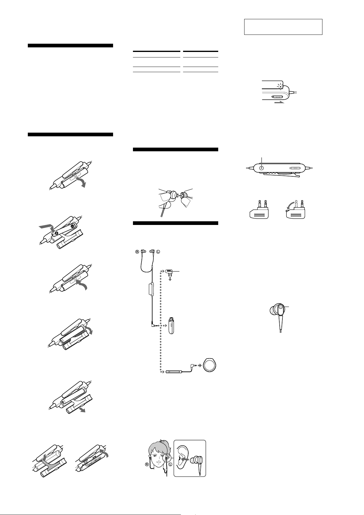
Installing a battery
1
Open the lid on the rear of the battery box.
2
Insert one R03 (size AAA) battery, matching
the + and – on the battery to the + and – in the
battery compartment.
Insert the # end
first.
3
Close the lid.
Removing the battery
1
Open the lid.
Battery life
Battery
Sony alkaline battery LR03/AM4 (N)
Sony battery R03/UM-4 (NU)
*11 kHz, 1 mW + 1 mW input
2
*
Time stated above may vary, depending on the temperature
or conditions of use.
When to replace the battery
Replace the battery with a new one when the POWER
indicator dims.
Note
(US, Tourist models)
Because the supplied battery was included in the package from
the time of manufacture (as a convenience to the user), it is
possible that the battery life may be somewhat depleted by the
time of purchase. The actual life of the supplied battery may be
shorter than the standard time described in this manual when
using a fresh battery.
Approx. hours*
50 hours*
22 hours*
1
2
2
Selecting the
earbuds
The M size earbuds are attached to the headphones before
shipment. If you feel the M size earbuds do not suit your
ears, replace them with the supplied S or L size earbuds.
Listening to music
Connect the headphones to the AV equipment.
1
When connecting to dual or
stereo mini jacks of in-flight
music services.
Plug adaptor (supplied)
To headphone jacks
on airplane seats
When directly connecting to
the headphone jack (stereo
mini jack) of a WALKMAN
etc.
*
,
3
Turn on the power of the headphones.
The power indicator lights in red. The power
switch is located on the battery box. When
power is turned on, ambient noise is reduced,
and you can listen to music more clearly at a
lower volume.
4
Turn on the power of the AV equipment.
* “WALKMAN” and “WALKMAN” logo are registered
trademarks of Sony Corporation.
To hear ambient sound for safety
When the power switch is set to on, noise canceling can be
deactivated while the MONITOR button is pressed so that
you can hear ambient sound.
MONITOR button
Notes on using on the airplane
• The supplied plug adaptor can be connected to the dual or
stereo mini jacks of in-flight music services.
dual jacks stereo mini jacks
• Do not use the headphones when use of electronic
equipment is prohibited or when use of personal
headphones for in-flight music services is prohibited.
If you have any questions or problems concerning the
system that are not covered in this manual, please consult
the nearest Sony dealer.
After listening to music
Turn off the power of the headphones.
Notes
• The noise canceling function is only effective for noise in the
low frequency band. Although noise is reduced, it is not
canceled completely.
•Do not cover the microphone of the headphones with your
hands. The noise canceling function may not work properly.
Microphone
• The noise canceling function may not work properly unless
the headphones are put on firmly.
•You can use the headphones even without turning on the
power. In this case, the noise canceling function is not active,
and the headphones operate as passive headphones.
•After you turn on the power of the headphones, you may hear
a slight hiss. This is the operating sound of the noise canceling
function, not a malfunction.
• In a quiet place, or depending on certain noises, you may feel
that the noise canceling function is not effective, or that noise
is accentuated. In this case, turn off the power of the
headphones.
• Interference noise can occur from nearby cellular phones.
Should this occur, locate the headphones further away from
the cellular phone(s).
2
Pull the lid lightly in the direction of the arrow.
Note
The battery may jump out when the lid is pulled. Pull the
lid while placing a finger on the battery.
3
Close the lid.
Note
Store the ribbon in the battery compartment to prevent it
being pinched by the lid.
When connecting to a remote
commander with a stereo
mini jack of a WALKMAN
etc.
Remote commander
2
Wear the headphones marked R in your right
ear and the one marked L in your left ear. Push
the earbud into your ear carefully so that the
earbud fits the hole of your ear snugly.
Note
Unless the earbuds correctly fit your ears, noise canceling
will not function.
Adjust the earbuds position to sit on your ear comfortably,
and push them into the inside of your ears so that they fit
your ears snugly.
*
,
c
2
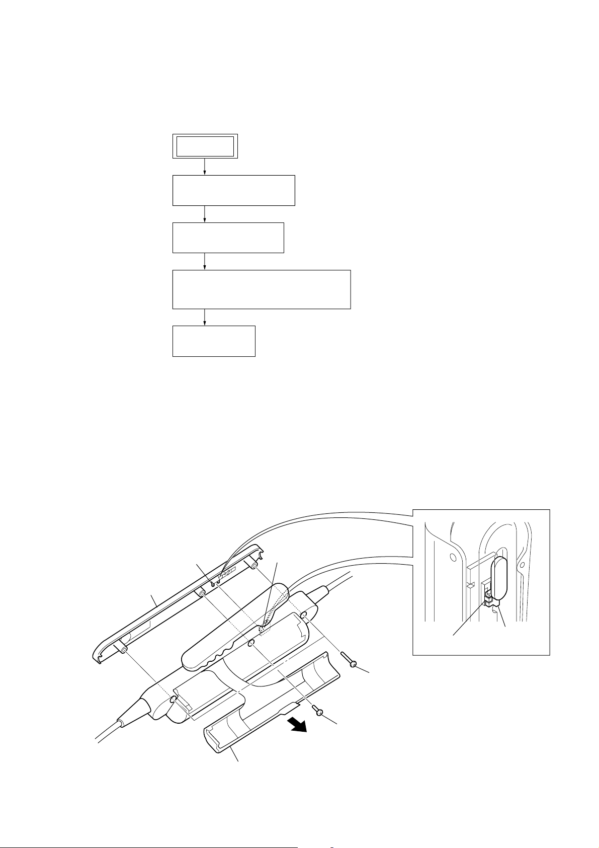
• This set can be disassembled in the order shown below.
2-1. DISASSEMBLY FLOW
SET
2-2. CABINET FRONT ASSY
(Page 3)
2-3. LIGHT GUIDE PLATE
(Page 4)
2-4. HEADPHONE ASSY,
CORD (WITH PLUG) (LINE INPUT) (P1)
(Page 4)
MDR-NC22
SECTION 2
DISASSEMBLY
2-5. MAIN BOARD
(Page 5)
Note: Follow the disassembly procedure in the numerical order given.
2-2. CABINET FRONT ASSY
Note: On installation of cabinet front assy,
adjust the position of switch (S101)
and power knob.
switch (S101)
4
cabinet front assy
power knob
2
Open the battery case lid.
3
screw (1.7)
1
two screws
(1.7)
switch (S101)
power knob
3

MDR-NC22
)
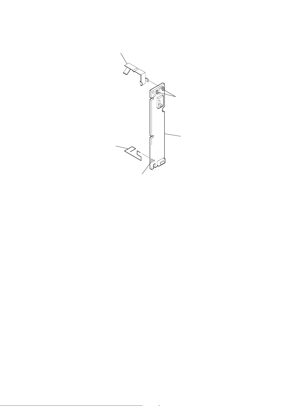
2-3. LIGHT GUIDE PLATE
1
Remove the headphone assy,
MAIN board and cord (with plug)
(line input) (P1) in the direction
of the arrow.
2
light guide plate
headphone assy
MAIN board
cord (with plug) (line input) (P1
2-4. HEADPHONE ASSY, CORD (WITH PLUG) (LINE INPUT) (P1)
2
headphone assy
1
Remove five solders
of headphone assy.
CORD (WITH PLUG) (LINE INPUT) (P1)
WIRING DIAGRAM
MAIN board
(side B)
green
HEADPHONE ASSY
WIRING DIAGRAM
headphone assy
red
brown
cord (with plug) (line input) (P1)
4
green
red
3
Remove three
solders of cord
(with plug)
(line input) (P1).
4
cord (with plug) (line input)
(P1)
brown
white
black
MAIN board (side A)
2-5. MAIN BOARD
2
4
terminal battery (+)
terminal battery (–)
1
Remove two solders
of terminal battery (–).
5
MAIN board
MDR-NC22
3
Remove solder of
terminal battery (+).
5
 Loading...