

Page 1

3-043-018-12(1)
Digital Surround
Headphone
System
Operating Instructions
Mode d’emploi
Manual de instrucciones
GB
FR
ES
MDR-DS5100
©1999 Sony Corporation
Page 2

WARNING
NOTICE FOR THE CUSTOMERS IN THE
U.S.A.
To prevent fire or shock
hazard, do not expose the unit
to rain or moisture.
To avoid electrical shock, do
not open the cabinet. Refer
servicing to qualified
personnel only.
WARNING
You are cautioned that any changes or
modifications not expressly approved in
this manual could void your authority to
operate this equipment.
For the customers in the USA
Owner’s Record
The model number is located on the back
of the processor and on the headphone
housing.
The serial number is located at the
bottom of the processor and the inner
side of the battery compartment.
Record these numbers in the spaces
provided below. Refer to them whenever
you call upon your Sony dealer
regarding this product.
NOTE
This equipment has been tested and found to
comply with the limits for a Class B digital
device, pursuant to Part 15 of the FCC Rules.
These limits are designed to provide
reasonable protection against harmful
interference in a residential installation. This
equipment generates, uses, and can radiate
radio frequency energy and, if not installed
and used in accordance with the instructions,
may cause harmful interference to radio
communications. However, there is no
guarantee that interference will not occur in a
particular installation. If this equipment does
cause harmful interference to radio or
television reception, which can be determined
by turning the equipment off and on, the user
is encouraged to try to correct the interference
by one or more of the following measures:
– Reorient or relocate the receiving antenna.
– Increase the separation between the
equipment and receiver.
– Connect the equipment into an outlet on a
circuit different from that to which the
receiver is connected.
– Consult the dealer or an experienced radio/
TV technician for help.
You are cautioned that any changes or
modifications not expressly approved in this
manual could void your authority to operate
this equipment.
Model No. MDR-DS5100
Processor DP-IF5100
Headphones MDR-IF5000
Serial No.
Processor
Headphones
GB
2
Page 3

For the customers in the USA and
Canada
Table Of Contents
RECYCLING NICKEL-CADMIUM BATTERIES
Nickel Cadmium batteries
are recyclable. You can help
preserve our environment
by returning your unwanted
batteries to your nearest
point for collection,
recycling or proper disposal.
Note: In some areas the disposal of nickel
cadmium batteries in household or
business trash may be prohibited.
RBRC (Rechargeable Battery Recycling
Corporation) advises you about spent battery
collection by the following phone number.
Call toll free number: 1-800-822-8837
(United States and Canada only)
Caution: Do not handle damaged or leaking
nickel-cadmium batteries.
Location and Function of Parts... 5
Front Panel of the Digital Surround
Processor...........................................
Rear Panel Parts Descriptions of
the Digital Surround Processor .....
Headphone Parts Descriptions ......... 7
Starting Operation ...................... 8
Checking the Products and
Accessories ....................................
Charging the Batteries .............. 10
Charging the batteries ...................... 10
Charging............................................. 11
Connecting the Headphone
System ..................................... 13
Setup ................................................... 13
Connecting the digital surround
processor with digital
components ....................................
Connecting the digital surround
processor with analog
components ....................................
Plugging into the wall outlet........... 17
Inserting the batteries in the
headphones ....................................
14
15
18
5
6
8
GB
Listening to the Sound of the
Connected Component .......... 20
Additional Headphones .................. 27
Troubleshooting......................... 28
Precautions................................. 30
Specifications ............................. 31
3
GB
Page 4

Main features
The MDR-DS5100 is a digital surround headphone system using infrared
transmission. You can enjoy multichannel surround sound with headphones by
simply connecting the digital surround processor to a DVD player with the supplied
optical digital connecting cable.
• Compatible with Dolby
• Virtual Dolby Digital and DTS Virtual 5.1 certified.
• Signal processing by the Logic 3D processor creates surround sound for the
headphones that simulates a movie theater.
• Cordless headphones using infrared transmission system resistant to external noise
and interference.
• Wide infrared reception range of up to 10 m.
• Self adjusting mechanism eliminating the need for headband adjustment.
• Auto Power On/Off Function to automatically turn on the headphones when they
are put on and to turn them off when they are taken off.
• VOL control for adjusting both the right and left volume of the headphones.
The left and right audio output level is adjustable using the BALANCE control.
• Additional MDR-IF5000 headphones (sold separately) can be used at the same time
so that more than one person can enjoy the surround sound experience.
• Equipped with a headphone jack to connect corded open-air headphones (The
headphone jack is adjusted for the MDR-F1 corded full-open air type headphone
(sold separately), so connecting the MDR-F1 allows you to enjoy high quality
surround sound with the same surround effect as the supplied headphones MDRIF5000.).
• Rechargeable Ni-Cd batteries (supplied and sold separately) or R6 (size AA) drycell batteries (sold separately) can be used to power the headphones.
* Digital (AC-3), Dolby Surround (Pro Logic) and DTS*.
* The digital surround processor for this system incorporates the Dolby Digital (AC-3)
decoder and the DTS decoder.
Manufactured under license from Dolby Laboratories Licensing Corporation and Digital
Theater Systems, Inc.
DOLBY, the double-D symbol a, “PRO LOGIC”, “Dolby Digital (AC-3)”, and “VIRTUAL
DOLBY DIGITAL” are trademarks of Dolby Laboratories Licensing Corporation.
“DTS” and “DTS VIRTUAL 5.1” are trademarks of Digital Theater Systems, Inc.
CE mark
The CE mark is valid for products marketed in the European Union only.
GB
4
Page 5

¡ Preparation
Location and Function of Parts
1 DIGITAL input indicator
Front Panel of the Digital Surround Processor
123
POWER
DIGITAL
ANALOG
INPUT
CINEMA
MUSIC
EFFECT
DECODE MODE
DOLBY DIGITAL
DOLBY SURROUND
DTS
LRC
LS RS
VIRTUAL
OUTPUT
PHONES LEVEL
MIN MAX
4
5
6
8
7
ANALOG input indicator
INPUT button
Press to select the input source
(DIGITAL/ANALOG).
2 POWER indicator
This indicator lights green when you
turn on the digital surround processor.
POWER switch
Press to turn on and off the digital
surround processor.
3 CINEMA indicator
MUSIC indicator
EFFECT button (see page 21 for
details)
Press to select the sound field
(CINEMA/MUSIC).
4 Decode mode display (see page 23
for details)
5 PHONES jack (see page 27 for
details)
Connect your headphones to this jack.
Connect the MDR-F1 headphone (sold
separately) for optimum surround effect.
6 PHONES — LEVEL control
Turn to adjust the volume of the
headphones (sold separately) connected
to the PHONES jack.
7 OUTPUT button
Press to select the output mode (OFF/
VIRTUAL FRONT/VIRTUAL
SURROUND).
8 Infrared emitter
Set the emitter in a position so that there
is a straight, unobstructed path to the
sensor.
(Continued)
Preparation
GB
5
Page 6

Rear Panel of the
34
Digital Surround
Processor
12
1 DIGITAL IN jack (see page 14 for
details)
Connect a DVD player, LD player, or
other digital component (sold separately)
to this jack.
2 ATT (attenuator) switch
Set this switch to 0dB when the volume is
too low at analog input. Normally, this
switch should be set to –8dB.
3 LINE INPUT jack (see page 15 for
details)
Connect the audio output jack on audio/
video equipment (sold separately), such
as a video cassette player or TV, to this
jack.
4 DC IN jack
Connect the supplied AC power adapter
to this jack. (Be sure to use the supplied
AC power adapter. Using products with
different plug polarity or other
characteristics can cause a malfunction.)
GB
6
Preparation
Page 7

Headphone Parts Descriptions
4
3
2
1
1 Infrared sensor
There are infrared sensors in four
locations on both sides.
2 Battery case
Press and lift up the lid to open it. This
battery case is for the supplied
rechargeable batteries and R6 (size AA)
batteries only.
3 Self-adjusting band
The headphones automatically turn on
when you put on the headphones.
4 BALANCE control
Use to adjust the left and right sound
balance.
5 POWER indicator
This indicator lights red when you put
on the headphones.
5
6
1
7
8
6 VOL control
Use to adjust the volume.
7 Driver (right)
To replace the ear pads, consult your
nearest Sony dealer.
8 Driver (left)
Preparation
GB
7
Page 8
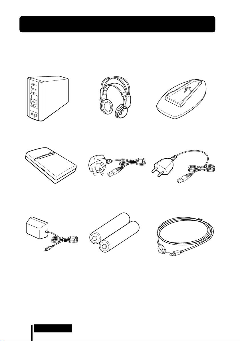
Starting Operation
1 Checking the Products and Accessories
Before setting up the system, check that all of the components are included.
Cordless stereo headphones (1)Digital surround processor (1)
Battery charger (1) Charging plug (for battery
AC power adapter (1)
charger, 1)
(CEK and HK4 Versions
Rechargeable Ni-Cd batteries
NC-AA (2)
* only)
Stand (for digital surround
processor, 1)
Charging plug (for battery
charger, 1)
(CED and E13 Versions* only)
Optical digital connecting cable
(rectangular type y rectangular
type, 1)
* The charging plug supplied with this system varies depending on the system version. To check
the version, refer to the version code printed on the box.
GB
8
Preparation
Page 9

2 Charging the Batteries (see page 10 for details)
3 Connecting the Headphone System (see page 13 for
details)
4 Listening to the Sound of the Connected
Component
(see page 20 for details)
Preparation
GB
9
Page 10

¡ Operation
Charging the Batteries
Charging the batteries
The supplied rechargeable batteries should be recharged before using them for the
first time.
Be sure to use the supplied battery charger. Up to four batteries can be charged at
once.
Inserting the batteries into the battery charger
1 Open the lid.
Note
Press the rechargeable Ni-Cd batteries into the charger until they fit into place. After inserting
the batteries, close the lid firmly. The batteries will not be charged unless the lid is closed.
2 Insert the two supplied rechargeable Ni-Cd
batteries NC-AA with the ‘ and ’ ends in the
correct direction.
10
GB
Operation
Page 11

Charging
(U2, CA2 and E92 Versions* only)
1 Pull out the charging plug. 2 Insert into the wall outlet.
Charge indicator
lights up.
(CEK and HK4 Versions* only)
1 Attach the charging plug to the battery charger. 2 Insert into the wall outlet.
Charge indicator
lights up.
(CED and E13 Versions* only)
1 Attach the charging plug to the battery charger. 2 Insert into the wall outlet.
Charge indicator
lights up.
* The charging plug supplied with this system varies depending on the system version. To check
the version, refer to the version code printed on the box.
(Continued)
Operation
11
GB
Page 12

When charging is finished
After the charging time has elapsed, unplug the charger from the outlet, and take out
the rechargeable Ni-Cd batteries.
Standard charging times and usage times for the supplied rechargeable batteries
Charging time Usage time
Approx. 1 hour Approx. 6 hours
Approx. 6 hours* Approx. 30 hours
* Time to fully charge the battery when it is completely drained.
Notes
• The charging time for the batteries is the same regardless of
the number of batteries.
• During charging, the charger and the batteries become
slightly warm. This is not a malfunction.
• Be sure to unplug the charger when it is not being used.
• Do not use or leave the charger near heating components,
hot areas exposed to direct sunlight, or damp areas.
• The batteries will not be charged if the adjuster on the
charger is pushed down. Set the adjuster back in the
direction of the arrow shown in the illustration at the right
before charging.
• The charging indicator may turn off sooner than usual when charging batteries that have not
been completely discharged.
Adjuster
12
GB
Operation
Page 13

Connecting the Headphone System
Setup
You can place the digital surround processor in an upright position or on its side.
To use in an upright position:
Use a coin to attach the supplied stand to the bottom of the digital surround
processor.
To use on its side:
Place the digital surround processor so that the four rubber supports are on the
bottom.
/
Rubber supports
Notes
• Install the digital surround processor in a location where there are no obstructions between the
processor and headphones when used.
• Do not install the digital surround processor in unstable locations, such as on top of the TV. If
the processor falls down, it could cause an injury or be damaged.
• If the digital surround processor is placed in an upright position, always attach the stand for
added safety.
• If the digital surround processor is placed on its side, the full infrared transmission range may
not be obtained depending on installation conditions.
• If the digital surround processor is placed on its side, do not place the digital surround
processor on the side not having the rubber supports.
(Continued)
Operation
13
GB
Page 14

Connecting the digital surround processor with digital components
Use the supplied optical digital connecting cable to connect the optical digital output
jack on a DVD player (or LD player), digital satellite tuner, or other digital component
to the DIGITAL IN jack of the digital surround processor.
Digital surround
processor
To DIGITAL IN jack
To optical digital
output jack
Optical digital connecting cable (supplied)
Take off the cap on the jack, match the orientation of the plug
with the jack, and then insert until the plug fits into place.
Notes
• The optical digital connecting cable is an extremely high-precision device and is sensitive to
jolts and external pressure. Therefore, be careful when inserting and removing the cable plug.
• This system is not provided with the AC-3 RF jacks, and so AC-3 RF signals from LD players
cannot be directly input.
• The digital input for the digital surround processor does not support sampling frequencies of
96 kHz. Set the digital output setting for the DVD player at 48 kHz when using this system.
Noise may be heard when a 96 kHz digital signal is input.
DVD player, LD player, digital
satellite tuner, or other digital
component having an optical
digital output jack
DTS
• A DTS-compatible DVD player is required for the playback of DVDs recorded in
DTS audio. (For more details, see the instruction manual of the DVD player.)
• When playing back sources recorded in DTS audio, press the INPUT button on the
processor to select “DIGITAL”.
• When playing LDs and CDs recorded in DTS format, noise may occur at the start of
playback or when fast forwarding. This is not a malfunction.
GB
14
Operation
Page 15

Connecting cables (sold separately)
Use the POC-5AB (mini-plug y rectangular plug, sold separately) when connecting the digital
output mini-jack on portable DVD players, portable CD players, or other digital components to
the DIGITAL IN jack.
Optical digital selector (sold separately)
Use of the SB-D30 (Optical digital selector (3-line input, 2-line output), sold separately) is
recommended when connecting more than one digital component.
Notes on optical digital connecting cable
• Do not drop objects on the optical digital connecting
cable or expose the cable to shocks.
• Grasp the plug to connect or disconnect the cable.
• Be sure that the ends of the optical digital connecting
cable are kept clean. Dust at the ends of the cable can
degrade performance.
• When storing the system, attach the cap to the end of the
plug and be careful not to fold or bend the optical digital
connecting cable with a bend radius less than 25 mm.
The bend radius of the optical
digital connecting cable should be
at least 25 mm.
25 mm
Connecting the digital surround processor with analog components
Use an audio cord (sold separately) to connect to the audio output jacks on the VCR,
TV, or other component to the LINE INPUT (L/R) jacks on the digital surround
processor.
Digital surround
processor
VCR, TV, or other
To LINE INPUT jacks
Audio left (L, white)
Audio cord
(sold separately)
Audio right (R, red)
Connecting cables (sold separately)
Use the RK-G129 cable (stereo mini-plug ˜ pin plug x 2) when connecting the stereo mini-jack
(line out jack or headphones jack) to the LINE INPUT jacks.
In this case, set the volume on the player at around 5 to 7. Noise can occur if the volume on the
player is set to a low setting.
See page 31 for details about other connecting cables (sold separately).
To audio output jacks
Audio left (white)
Audio right (red)
component
(Continued)
Operation
15
GB
Page 16

Setting the input level
If the volume is low using analog input, set the ATT (attenuator) switch to “0dB”.
ATT
0dB
–8dB
Setting Connected components
0dB TV, portable components, and other components with a low output level
–8dB Other components (initial settings)
Notes
• Be sure to lower the volume before setting the ATT (attenuator) switch.
• If the audio input to LINE INPUT jacks is distorted, set the ATT (attenuator) switch to “–8dB”.
16
GB
Operation
Page 17

Plugging into the wall outlet
Digital surround
processor
AC power
adapter
To the wall outlet
To DC IN jack
Notes
• Be sure to use the supplied AC power adapter. Using AC adapters with different plug polarity
or other characteristics can cause product failure.
Unified polarity plug
• Be sure to always use the supplied AC power adapter. Even AC power adapters having the
same voltage and plug polarity can break the product due to the current capacity or other
factors.
(Continued)
Operation
17
GB
Page 18

Inserting the batteries in the headphones
As shown in the illustration below, insert two fully-charged (page 10) rechargeable
Ni-Cd batteries with the ‘ and ’ ends in the correction direction.
12 3
When using optional batteries
You can also use R6 (size AA) dry-cell batteries, Sony R6 (size AA) rechargeable NiCd batteries (NC-AA, NC-AAS), and R6 (size AA) rechargeable nickel-hydrium
batteries (NH-AA) with the headphones. Insert the batteries as shown above.
Usage times for dry-cell batteries
Battery type Usage time
Sony Alkaline Battery LR6/AM3 (N) Approx. 90 hours
Sony Manganese Battery R6P/SUM-3 (NS) Approx. 45 hours
Usage times and charging times for Sony rechargeable batteries (sold
separately)
Battery type Usage time Charging time*
Sony R6 (size AA) Ni-Cd Battery
NC-AA (700 mAh)
Sony R6 (size AA) Ni-Cd Battery
NC-AAS (1000 mAh)
Sony R6 (size AA) Nickel-hydrium Battery
NH-AA (1450 mAh)
Approx. 30 hours Approx. 6 hours
Approx. 40 hours Approx. 9 hours
Approx. 60 hours Approx. 10 hours
* Time to fully charge the battery when it is completely drained.
GB
18
Operation
Page 19

When charging R03 (size AAA) batteries
The supplied battery charger can also charge Sony
R03 (size AAA) Ni-Cd batteries (NC-AAA) and R03
(size AAA) nickel-hydrium batteries (NH-AAA).
When charging R03 (size AAA) batteries, push down
the adjuster on the battery charger.
When charging R6 (size AA) batteries, flip up the
adjuster.
Adjuster
Charging times for R03 (size AAA) rechargeable
batteries
Battery type Charging time*
Sony R03 (size AAA) Ni-Cd Battery
NC-AAA (250 mAh)
Sony R03 (size AAA) Nickel-hydrium Battery
NH-AAA (650 mAh)
Approx. 5 hours
Approx. 10 hours
* Time to fully charge the battery when it is completely drained.
Notes
• The supplied battery charger can charge Sony R6 (size AA) Ni-Cd batteries (NC-AA, NC-AAS)
and Sony R6 (size AA) nickel-hydrium batteries (NH-AA). Never attempt to charge other
types of rechargeable batteries or dry-cell batteries.
• Do not use Sony R6 (size AA) Ni-Cd batteries, NC-AA (HJ).
• The Ni-Cd batteries should be replaced with new ones when they last only half the expected
time when fully charged. Purchase either Sony R6 (size AA) Ni-Cd batteries (NC-AA,
NC-AAS) or Sony R6 (size AA) nickel-hydrium batteries (NH-AA). You can order the batteries
from the store where you made the purchase or at your nearest Sony dealer.
• Some battery types may not be available in certain areas.
Operation
19
GB
Page 20

Listening to the Sound of the Connected Component
Before starting operation, be sure to read “Connecting the
Headphone System” and make the proper connections.
1 Turn on the component connected to the digital surround processor.
DVD player or other audio
and video component
2 Press POWER to turn on the digital surround processor.
The POWER indicator lights green.
POWER
POWER
3 Put on the headphones.
The POWER indicator lights red, and the headphones automatically turn on.
BALANCE
P
O
W
E
R
VOL
20
GB
POWER
indicator
Operation
Page 21

4 Press INPUT to select the component you want to listen to.
DIGITAL
ANALOG
INPUT
Indicator light Selected sound source
DIGITAL Sound of the component connected to DIGITAL IN jack
ANALOG Sound of the component connected to LINE INPUT jacks
Note
To listen to dual audio (MAIN/SUB) sound sources, connect to the LINE INPUT jacks, and
then select the sound source you want to listen to on the player, TV, or other component.
5 Press OUTPUT to select the output mode (surround effect) (see page 22).
DECODE MODE
DECODE MODE
DOLBY DIGITAL
DOLBY DIGITAL
DOLBY SURROUND
DOLBY SURROUND
DTS
L
L
LS
LS
C
C
VIRTUAL
OUTPUT
OUTPUT
R
R
RS
RS
(Continued)
Operation
21
GB
Page 22

Indicator light Output mode (surround effect)
DECODE MODE
DECODE MODE
DOLBY DIGITAL
DOLBY DIGITAL
DOLBY SURROUND
DOLBY SURROUND
DTS
C
C
L
L
LS
LS
VIRTUAL
RS
RS
R
R
OFF
Regular headphone playback.
DECODE MODE
DECODE MODE
DOLBY DIGITAL
DOLBY DIGITAL
DOLBY SURROUND
DOLBY SURROUND
DTS
C
C
L
L
LS
LS
VIRTUAL
R
R
RS
RS
VIRTUAL FRONT
Virtual effect where the sound seems to be coming from two
speakers (right and left) located in front of you.
VIRTUAL SURROUND
DECODE MODE
DECODE MODE
DOLBY DIGITAL
DOLBY DIGITAL
DOLBY SURROUND
DOLBY SURROUND
DTS
C
C
L
L
R
R
Virtual surround effect where the sound seems to be coming from
not only two front speakers (right and left), but also from one center
speaker, two rear speakers (right and left), and a subwoofer (when
DOLBY DIGITAL and DTS are lit).
The digital surround processor automatically identifies and
processes according to the format of the input audio signal.
LS
LS
VIRTUAL
RS
RS
When DOLBY DIGITAL indicator is on: Audio recorded in Dolby
Digital 5.1ch format is being processed.
When DOLBY SURROUND indicator is on: Audio recorded in Dolby
Surround (Pro Logic) format is being processed.
When DTS indicator is on: Audio recorded in DTS 5.1ch format is
being processed.
Notes
• The processor automatically recognizes the decode mode (DOLBY DIGITAL/DOLBY
SURROUND/DTS), and the respective indicator light turns on. Select Dolby Digital or
DTS audio for the audio output at the connected player.
• The decode mode becomes DOLBY SURROUND in the following cases.
– When the signal received by digital input is PCM
– During analog input
22
GB
Operation
Page 23

6 Press EFFECT to select the desired sound field.
CINEMA
MUSIC
EFFECT
Indicator light Sound field and suitable sound source
CINEMA Mode which reproduces the sound field of a movie theater.
This mode is suitable for movie sound sources.
MUSIC Mode which reproduces the sound field of a listening room with
good acoustic environment.
This mode is suitable for music sources.
Note
If the output mode (sound effect) is set to “OFF” in step 5 on page 21, you cannot select a
sound field even if you press EFFECT.
7 Adjust the volume.
Raise the
volume
Lower the
volume
BALANCE
P
O
W
E
R
VOL
To adjust the volume of headphones (sold separately) connected to the
PHONES jack
Turn PHONES—LEVEL to adjust the volume.
MIN
LEVEL
Raise the
volume
MAX
PHONES
Lower the
volume
Note
When watching movies, be careful not to raise the volume too high in quiet scenes. You can
hurt your ears when a loud scene is played.
(Continued)
Operation
23
GB
Page 24

8 Adjust the balance.
The right side
becomes louder.
The left side
becomes louder.
BALANCE
P
O
W
E
R
VOL
The headphones automatically turn off when they are taken off
— Auto Power On/Off Function
When not using the headphones, be sure
that the self-adjusting band is no longer
Self-adjusting
band
pulled up. The power stays on when the
self-adjusting band is pulled up.
To check the remaining battery power
Pull up the self-adjusting band and check
the POWER indicator. The batteries can be
used when the POWER indicator lights red.
Charge the batteries or use new dry-cell
batteries if the POWER indicator is faint,
the sound is distorted, or increased noise is
heard.
POWER
indicator
After using the headphone system
Turn off the digital surround processor first before turning off the component
connected to the digital surround processor. If you turn off the connected component
first, the infrared beam is cut off and noise may be emitted (this is not a malfunction).
Do not hang the headphones on the digital surround processor or other components.
The Auto Power On Function may be inadvertently activated, using up the batteries.
Transition time between modes
When pressing buttons on the digital surround processor to change to new modes,
the transition time between modes may vary. This is due to differences in program
transmission between modes.
Mute Function
The Mute Function is automatically activated so that sound output from the
headphones is cut off when the headphones are outside the infrared transmission
area, or when the infrared beams are interrupted. The Mute Function is automatically
cancelled when you get closer to the digital surround processor or there is no longer
anything in the way of the infrared beams.
GB
24
Operation
Page 25

Infrared transmission area
The approximate infrared transmission area from the digital surround processor is
shown in the illustration below.
Infrared beams
Approx.
Digital surround
processor
Notes
• Because this system uses infrared beams, even if the headphones are within the transmission
area shown above, electrical noise (hissing noises) may increase as the headphones get farther
away from the digital surround processor. Also, if the infrared beams are blocked, the sound
may be interrupted or noise may be heard. This is due to the infrared beam characteristics and
is not a malfunction.
• Do not cover the infrared beam sensor with your hand or hair.
• As long as the headphones are in the transmission area shown in the illustration above, the
headphones can have any orientation with respect to the digital surround processor (facing,
turned 90°, or turned 180°).
• The sound may differ depending on the digital surround processor position and conditions in
the room. It is recommended that you place the digital surround processor in the location
which produces the clearest sound.
• Mixed signals may result if the digital surround processor is used with other processors or
transmitters.
4 m
Approx.
4 m
45°
45°
Approx.
10 m
(Continued)
Operation
25
GB
Page 26

How to attach the battery cover when it has come off
As shown in the illustration, align A with A, and B with B, and then attach the
cover in place.
A
B
B
A
If an audio signal is not input for 10 minutes
Emission of the infrared beams from the digital surround processor automatically
stops when an audio signal is not input for 10 minutes. The infrared beams are
automatically emitted when an audio signal is input again. The emission of the
infrared beams may stop when an extremely low sound is emitted for about 10
minutes during analog input. If this happens, raise the volume of the connected audio
and video component and lower the volume of the headphones.
Notes
• There may be differences in brightness of the infrared transmitter on the digital surround
processor. However, this does not affect the transmission area.
• The headphones should be used within the infrared transmission area (see “Infrared
transmission area” on page 25).
• Do not use the digital surround processor in areas exposed to direct sunlight or strong light.
The sound may be interrupted.
• These open-air headphones are designed so that the sound also flows outside the headphones.
Be careful not to turn up the volume too high that it bothers the people around you.
• Use a suitable volume level so that you do not harm your hearing and to ensure that you can
still hear surrounding sounds.
• The surround sound effect may not be obtained for sound sources which do not incorporate
video, such as music CDs.
• This system simulates the HRTF* for an average person. However, the effect can differ from
person to person since the HRTF can vary between individuals.
* Head Related Transfer Function
GB
26
Operation
Page 27

Additional Headphones
Headphones can be added to this system in one of two ways.
To enjoy surround sound using cordless headphones with more than one person
t By using additional MDR-IF5000 cordless infrared headphones (sold separately),
more than one person can enjoy the surround sound experience at the same time.
* There is no limit to the number of headphones that can be used within the
infrared transmission area.
Digital surround
processor
MDR-IF5000 (sold separately)
To enjoy higher quality sound
t The PHONES jack is adjusted for the MDR-F1 corded full-open air type
headphone (sold separately), so connecting the MDR-F1 allows you to enjoy high
quality surround sound. You can also use any corded open-air headphones with
this system.
To obtain sufficient surround sound effect, use of MDR-IF5000 cordless stereo
headphones or MDR-F1 corded full-open type headphones is recommended.
Digital surround
processor
MDR-F1 corded full-open air type
headphones (sold separately) or other
corded open-air headphones
To PHONES jack
Notes
• When removing the headphones from the PHONES jack, always grip the plug. Never pull on
the cord.
• The surround effect may not be obtained when using closed-type and in-ear headphones.
Operation
27
GB
Page 28

¡ Additional Information
Troubleshooting
If you run into any problem using this headphone system, use the following checklist.
Should any problem persist, consult your nearest Sony dealer.
Symptom Cause and remedy
No sound
(both channels
or one channel)
Distorted sound
/ Turn on the digital surround processor.
/ Check that the AV component and AC power adapter are connected to the
digital surround processor and that they are plugged into the power outlet.
/ Turn on the AV component connected to the digital surround processor, and
start the program (playback).
/ Use the INPUT button to check whether the AV component you want to listen
to is properly selected.
/ If the AV component headphone jack is connected to the digital surround
processor, raise the volume level on the connected AV component.
/ Raise the headphone volume.
/ Check the position of the BALANCE control on the headphones.
/ The Mute Function is on.
• Check that there is nothing blocking the path from the digital surround
processor to the headphones.
• Try to use the headphones as close as possible to the digital surround
processor.
• Change the position or angle of the digital surround processor.
/ The POWER indicator on the headphones is faint or out. This indicates that
the battery power is low. If you are using rechargeable batteries, recharge the
batteries. If you are using dry-cell batteries, replace with new ones. If the
indicator is still out, consult your nearest Sony dealer.
/ You are trying to play a DTS audio track on a DVD player that does not
support DTS.
Either use a DVD player that supports DTS, or select a Dolby Digital or PCM
audio track.
/ Set the ATT (attenuator) switch on the digital surround processor to “–8dB”.
/ The POWER indicator on the headphones is faint or out. This indicates that
the battery power is low. If you are using rechargeable batteries, recharge the
batteries. If you are using dry-cell batteries, replace with new ones. If the
indicator is still out, consult your nearest Sony dealer.
/ If the AV component headphone jack is connected to the digital surround
processor, lower the volume level on the connected AV component.
/ When using DTS audio sources, set the processor output mode to VIRTUAL
SURROUND (page 23).
28
GB
Additional Information
Page 29

Symptom Cause and remedy
High noise level/
Low sound
The surround
sound effect is
not obtained
The DOLBY
DIGITAL indicator
does not turn on
DTS indicator light
does not turn on
The batteries
cannot be
charged
/ Use the headphones near the digital surround processor. The amount of noise
increases as the headphones become farther from the digital surround
processor. This is due to the characteristics of the infrared beams and is not a
malfunction.
/ Check that there is nothing blocking the path from the digital surround
processor to the headphones.
/ Check that your hand or hair is not covering the infrared sensor on the
headphones.
/ If direct sunlight is entering the room from a window near the digital
surround processor or headphones, close the curtain or blinds so that no direct
sunlight is let in. Or, use in a location not exposed to direct sunlight.
/ Change the position or angle of the digital surround processor.
/ Set the ATT (attenuator) switch on the digital surround processor to “0dB”.
/ The POWER indicator on the headphones is faint or out. This indicates that
the battery power is low. If you are using rechargeable batteries, recharge the
batteries. If you are using dry-cell batteries, replace with new ones. If the
indicator is still out, consult your nearest Sony dealer.
/ If the AV component headphone jack is connected to the digital surround
processor, raise the volume level on the connected AV component.
/ Press the OUTPUT button to select VIRTUAL SURROUND mode (page 23).
/ The audio for the chapter being played is not a multichannel signal.
The surround effect does not work for monaural and other sound sources
which have not been processed for surround sound.
/ The audio digital output setting for the DVD player may be set to “PCM”.
Refer to the instruction manual supplied with the DVD player, and change to
the setting (such as “Dolby Digital/PCM” or “Dolby Digital”) for usage with
components having built-in Dolby Digital (AC-3) decoders.
/ You are trying to play DVD software not compatible with Dolby Digital 5.1ch.
/ The audio for the chapter being played is not a multichannel signal.
/ The DTS digital output setting on the DVD player is set to OFF. Refer to the
instruction manual supplied with the DVD player, and set the DTS digital
output setting to ON.
/ You are trying to play DVD software that is not compatible with DTS format.
/ The audio for the chapter that you are playing back is not DTS.
/ The DVD player does not support DTS format.
Use a DVD player that supports DTS.
/ Dry-cell batteries are being used.
Insert the supplied or optional rechargeable batteries (page 10).
/ Rechargeable batteries other than supplied or optional batteries are being
used.
Insert the supplied or optional rechargeable batteries (page 10).
Additional Information
29
GB
Page 30

Precautions
On safety
• Do not drop, hit, or otherwise expose the
digital surround processor or headphones
to strong shocks of any kind. This could
damage the product.
• Do not disassemble or attempt to open any
parts of the system.
On power sources and placement
• If you are not going to use the system for a
long time, unplug the AC power adapter
cord from the outlet. When removing the
cord, grip the plug. Do not pull on the cord.
• Do not place the system at any of the
following locations.
– Location exposed to direct sunlight, near
a heater, or other extremely hightemperature location
– Dusty location
– On an unsteady or inclined surface
– Location exposed to large amounts of
vibrations
– Bathroom or other high-humidity
locations
On headphones
To protect your ears
Listening to sounds at a high volume over
long periods of time can harm your hearing.
To protect your ears, do not listen with the
volume raised too high.
Act considerately
When the volume is too high, the sound flows
outside the headphones. Be careful not to
raise the volume too high that it bothers the
people around you.
There is a tendency to raise the volume when
using in places with noise. However, the
volume should be kept at a level where you
can respond when called while listening to
the headphones.
On ear pads
The ear pads may deteriorate over long
periods of use and storage. To replace the ear
pads, consult your nearest Sony dealer.
On cleaning
Use a soft cloth slightly moistened with mild
detergent solution. Do not use solvents such
as thinner, benzene or alcohol as these may
damage the surface.
When the product breaks
• When the product breaks, or if a foreign
object gets inside the unit, immediately turn
off the power and consult your nearest
Sony dealer.
• When taking the system to Sony dealer, be
sure to take both the headphones and
digital surround processor.
30
GB
Additional Information
Page 31

Specifications
Digital surround processor (DP-IF5100)
Decoder functions Dolby Digital 5.1ch
Virtual sound function OFF
Modulation System Frequency modulation
Carrier wave frequency Right channel 2.8 MHz
Transmission distance Approx. 10 m to the
Transmission range 20 – 20,000 Hz
Distortion rate 1% or less (1 kHz)
Audio inputs Optical input
Power requirements DC 9 V (from the
Dimensions (w/h/d) Approx. 85 × 190 × 180
Mass Approx. 1.0 kg
and 2ch
Dolby Pro Logic
DTS
Virtual front
Virtual surround
Left channel 2.3 MHz
front
(rectangular-type) × 1
Analog input (pin jack
left/right) × 1
supplied AC power
adapter)
mm (3 3/8 × 7 1/2 × 7
1
/8 inch)
(1,000 g) (2 lb 30 oz)
Cordless stereo headphones
(MDR-IF5000)
Playback frequency range
Power requirements Rechargeable Ni-Cd
Mass Approx. 280 g (10 oz)
12 – 24,000 Hz
batteries (supplied) or
R6 (size AA) batteries
(dry-cell or
rechargeable, sold
separately)
(including the
supplied rechargeable
Ni-Cd batteries)
Supplied accessories
Stand for digital surround
processor (1)
AC power adapter (9 V) (1)
Rechargeable Ni-Cd
batteries (NC-AA) (2)
Battery charger (1)
Charging plug for battery
charger (1) (CED, CEK, HK4
and E13 Versions* only)
Optical digital connecting
cable (rectangular plug y
rectangular plug, 1.5 m) (1)
Operating Instructions (1)
Product Information (1)
Recommended accessories
Connecting cables RK-C310, RK-C315,
Optical digital selector SB-D30
Optical digital connecting cable
Design and specifications are subject to
change without notice.
RK-C320, RK-C330
(pin plug × 2 ˜ pin
plug × 2)
RK-G129 (stereo miniplug ˜ pin plug × 2)
POC-5A, POC-10A,
POC-15A
rectangular plug y
optical rectangular
plug)
POC-5AB, POC-10AB,
POC-15AB
rectangular plug ˜
optical mini-plug)
(optical
(optical
* The charging plug supplied with this
system varies depending on the system
version. To check the version, refer to the
version code printed on the box.
Additional Information
31
GB
Page 32

AVERTISSEMENT
Pour les utilisateurs aux Etats-Unis et
au Canada
Pour éviter tout risque
d’incendie ou d’électrocution,
n’exposez pas cet appareil à la
pluie ni à l’humidité.
Pour éviter tout choc
électrique, n’ouvrez pas le
coffret. Ne confiez les
réparations qu’à un technicien
qualifié.
AVERTISSEMENT
Tout changement ou modification non
expressément approuvé dans le présent
manuel risque d’annuler votre autorité à
utiliser cet appareil.
RECYCLAGE DES BATTERIES AU NICKELCADMIUM
Les batteries au nickelcadmium sont recyclables.
Vous pouvez contribuer à
préserver l’environnement
en rapportant les batteries
usées dans un point de
ramassage, recyclage ou
retraitement.
Remarque: Dans certain pays, il est interdit de
jeter les batteries au nickelcadmium avec les ordures
ménagères ou dans les poubelles
de bureau.
Questionnez chez RBRC (Rechargeable
Battery Recycling Corporation) pour les
batteries usées.
Le numéro est: 1-800-822-8837
(Etats-Unis et Canada uniquement)
Avertissement: Ne pas utiliser des batteries
au nickel-cadmium qui sont
endommagées ou qui fuient.
FR
2
Page 33

Table des matières
Emplacement et fonction des
commandes ............................... 5
Panneau avant du processeur
d’ambiance numérique...................
Commandes du panneau arrière
Description du processeur
d’ambiance numérique...................
Pièces du casque ................................. 7
Opérations préliminaires ............ 8
Vérification des produits et des
accessoires ........................................
Charge de la batterie................. 10
Charge de la batterie......................... 10
Charge ................................................ 11
Ecoute du son d’un composant
raccordé................................... 20
Casques supplémentaires ................ 27
Guide de dépannage ................. 28
Précautions................................. 30
5
Spécifications ............................. 31
6
8
Raccordement du système de
casque d’écoute ...................... 13
Installation ......................................... 13
Raccordement du processeur
d’ambiance numérique à des
composants numériques ..............
Raccordement du processeur
d’ambiance numérique à des
composants analogiques ..............
Branchement à la prise murale ....... 17
Mise en place des batteries dans le
casque d’écoute .............................
FR
14
15
18
FR
3
Page 34

Principales caractéristiques
Le MDR-DS5100 est un système d’écoute d’ambiance numérique utilisant une
transmission par infrarouge. Vous pouvez profiter d’un champ sonore d’ambiance
multicanal en raccordant simplement le processeur d’ambiance numérique à un
lecteur DVD au moyen du câble de raccordement numérique optique fourni.
• Compatible Dolby
• Homologation Virtual Dolby Digital et DTS Virtual 5.1.
• Le traitement du signal par le processeur Logic 3D fournit au casque d’écoute un
champ sonore d’ambiance simulant une salle de cinéma.
• Le casque d’écoute sans fil à transmission par infrarouge résiste au bruit extérieur et
aux interférences.
• Zone de réception infrarouge étendue, jusqu’à 10 mètres.
• Mécanisme de réglage automatique du bandeau de casque.
• Fonction de mise sous/hors tension automatique alimentant automatiquement le
casque lorsqu’il est porté et l’éteignant lorsqu’il est enlevé.
• Réglage du volume de gauche et de droite du casque d’écoute au moyen de VOL.
Le niveau de sortie audio de gauche et de droite se règle au moyen de BALANCE.
• Des casques d’écoute MDR-IF5000 supplémentaires (vendus séparément) peuvent
être utilisés afin que plusieurs personnes puissent apprécier en même temps le son
d’ambiance.
• Prise pour le raccordement d’un casque d’écoute plein-air (La prise de casque est
ajustée pour un casque d’écoute plein-air avec fil MDR-F1 (vendu séparément) ; le
raccordement d’un MDR-F1 vous permet donc d’apprécier un son d’ambiance de
haute qualité, avec le même effet d’ambiance que le casque d’écoute MDR-IF5000
fourni.).
• Le casque d’écoute peut être alimenté par des batteries Ni-Cd rechargeables
(fournies et vendues séparément) ou par des piles sèches R6 (format AA) (vendues
séparément).
* Digital (AC-3), Dolby Surround (Pro Logic) et DTS*.
* Le processeur d’ambiance numérique de ce système comporte le décodeur Dolby Digital
(AC-3) et le décodeur DTS.
Fabriqué sous licence de Dolby Laboratories Licensing Corporation et Digital Theater
Systems, Inc.
DOLBY, le symbole double-D a, PRO LOGIC, Dolby Digital (AC-3) et VIRTUAL DOLBY
DIGITAL sont des marques de Dolby Laboratories Licensing Corporation.
“DTS” et “DTS VIRTUAL 5.1” sont des marques de Digital Theater Systems, Inc.
Symbole CE
Le symbole CE n’est valide que pour des produits commercialisés dans l’Union Européenne.
FR
4
Page 35

¡ Préparation
Emplacement et fonction des
Panneau avant du processeur d’ambiance numérique
123
POWER
DIGITAL
ANALOG
INPUT
CINEMA
MUSIC
EFFECT
DECODE MODE
DOLBY DIGITAL
DOLBY SURROUND
DTS
LRC
LS RS
VIRTUAL
OUTPUT
PHONES LEVEL
MIN MAX
4
5
6
8
1 Témoin d’entrée DIGITAL
(numérique)
Témoin d’entrée ANALOG
(analogique)
Touche INPUT (entrée)
Appuyez sur cette touche pour
sélectionner la source d’entrée
(DIGITAL/ANALOG).
7
2 Témoin POWER (alimentation)
Ce témoin s’allume en vert lorsque vous
mettez le processeur d’ambiance
numérique sous tension.
Commutateur POWER (alimentation)
Appuyez sur ce commutateur pour
mettre le processeur d’ambiance
numérique sous et hors tension.
3 Témoin CINEMA (cinéma)
Témoin MUSIC (musique)
Touche EFFECT (effet) (voir page 21
pour plus de détails)
Appuyez sur cette touche pour choisir le
champ sonore (CINEMA/MUSIC).
4 Affichage du mode de décodage
(voir page 23 pour plus de détails)
5 Prise PHONES (casque) (voir page
27 pour plus de détails)
Raccordez le casque à cette prise.
Raccordez un casque d’écoute MDR-F1
(vendu séparément) pour obtenir un effet
d’ambiance optimum.
6 Commande PHONES — LEVEL
(niveau du casque)
Tournez cette commande pour régler le
volume du casque d’écoute (vendu
séparément) raccordé à la prise
PHONES.
7 Touche OUTPUT (sortie)
Appuyez sur cette touche pour choisir le
mode de sortie (OFF/VIRTUAL
FRONT/VIRTUAL SURROUND).
8 Emetteur infrarouge
Placez l’émetteur dans une position en
ligne droite, sans obstruction, vers le
capteur.
commandes
(Suite page suivante)
Préparation
FR
5
Page 36

Panneau arrière du
34
processeur d’ambiance
numérique
12
1 Prise DIGITAL IN (entrée
numérique) (voir page 14 pour plus
de détails)
Raccordez un lecteur DVD, un lecteur LD
ou un autre composant numérique
(vendu séparément) à cette prise.
2 Commutateur ATT (atténuateur)
Réglez ce commutateur sur 0dB lorsque
le volume à l’entrée analogique est trop
faible. Ce commutateur doit
normalement être réglé sur –8dB.
3 Prise LINE INPUT (entrée de ligne)
(voir page 15 pour plus de détails)
Raccordez la prise de sortie audio de
l’appareil audiovisuel (vendu
séparément), comme un magnétoscope
ou un téléviseur, à cette prise.
4 Prise DC IN (entrée CC)
Raccordez l’adaptateur d’alimentation
secteur fourni à cette prise. (Veillez à
n’utiliser que l’adaptateur d’alimentation
secteur fourni. L’utilisation d’un autre
adaptateur ayant une polarité de fiche
différente ou d’autres caractéristiques
peut provoquer un fonctionnement
défectueux).
FR
6
Préparation
Page 37

Pièces du casque
4
3
2
1
1 Capteur infrarouge
Des capteurs infrarouges se trouvent à
quatre emplacements sur les deux côtés.
2 Compartiment des batteries
Appuyez sur le couvercle et soulevez-le
pour l’ouvrir. Ce compartiment n’est
destiné qu’aux batteries rechargeables
fournies et à des piles sèches R6 (format
AA).
3 Bandeau à réglage automatique
Le casque se met automatiquement sous
tension lorsque vous le mettez.
4 Commande BALANCE (équilibre)
Utilisez cette commande pour ajuster
l’équilibre sonore gauche et droit.
5 Témoin POWER (alimentation)
Ce témoin s’allume en rouge lorsque
vous mettez le casque.
5
6
1
7
8
6 Commande VOL (volume)
Utilisez cette commande pour régler le
volume.
7 Ecouteur (droit)
Consultez votre revendeur Sony pour
remplacer les écouteurs.
8 Ecouteur (gauche)
Préparation
FR
7
Page 38

Opérations préliminaires
1 Vérification des produits et des accessoires
Avant d’installer le système, vérifiez la présence de tous les éléments.
Processeur d’ambiance
numérique (1)
Chargeur de batterie (1)
Adaptateur d’alimentation
secteur (1)
Casque d’écoute stéréo sans fil
(1)
Fiche de chargeur (pour chargeur
de batterie, 1)
* CEK et HK4
(versions
uniquement)
Batteries Ni-Cd rechargeables
NC-AA (2)
Support (pour processeur
d’ambiance numérique, 1)
Fiche de chargeur (pour chargeur
de batterie, 1)
(versions* CED et E13
uniquement)
Câble de raccordement numérique
optique (type rectangulaire y
type rectangulaire, 1)
* La fiche de charge fournie avec la chaîne varie en fonction de la version de la chaîne. Pour
vérifier la version, reportez-vous au code de version imprimé sur la boîte.
FR
8
Préparation
Page 39

2 Charge de la batterie (voir page 10 pour plus de détails)
3 Raccordement du système de casque
d’écoute
(voir page 13 pour plus de détails)
4 Ecoute du son d’un composant raccordé (voir
page 20 pour plus de détails)
Préparation
FR
9
Page 40

¡ Utilisation
Charge de la batterie
Charge de la batterie
Les batteries rechargeables fournies doivent être rechargées avant de les utiliser pour
la première fois.
Prenez soin d’utiliser le chargeur de batterie fourni. Jusqu’à quatre batteries peuvent
être chargées simultanément.
Mise en place des batteries dans le chargeur de batterie
1 Ouvrez le couvercle. 2 Insérez les deux batteries Ni-Cd rechargeables
Remarque
Enfoncez les batteries Ni-Cd rechargeables dans le chargeur jusqu’à ce qu’elles soient bien en
place. Après la mise en place des batteries, fermez soigneusement le couvercle. Les batteries ne
seront pas chargées si le couvercle n’est pas fermé.
NC-AA fournies en dirigeant correctement leurs
polarités ‘ et ’.
10
FR
Utilisation
Page 41

Charge
(versions* U2, CA2 et E92 uniquement)
1 Sortez la fiche de charge. 2 Branchez à la prise murale.
Le témoin de charge
s’allume.
(versions* CEK et HK4 uniquement)
1 Branchez la fiche de charge au chargeur de
batterie.
(versions* CED et E13 uniquement)
1 Branchez la fiche de charge au chargeur de
batterie.
2 Branchez à la prise murale.
Le témoin de charge
s’allume.
2 Branchez à la prise murale.
Le témoin de charge
s’allume.
* La fiche de charge fournie avec la chaîne varie en fonction de la version de la chaîne. Pour
vérifier la version, reportez-vous au code de version imprimé sur la boîte.
(Suite page suivante)
Utilisation
11
FR
Page 42

Lorsque la charge est terminée
Lorsque la durée de charge s’est écoulée, débranchez le chargeur de la prise et sortez
les batteries Ni-Cd rechargeables.
Durées de charge et d’utilisation standard pour les batteries rechargeables
fournies
Durée de charge Durée d’utilisation
1 heure environ 6 heures environ
6 heures* environ 30 heures environ
* Durée pour la charge complète d’une batterie entièrement épuisée.
Remarques
• La durée de charge des batteries est indépendante du
nombre de batteries.
• Le chargeur et les batteries s’échauffent légèrement pendant
la charge. Ce n’est pas le signe d’un mauvais
fonctionnement.
• Prenez soin de débrancher le chargeur lorsqu’il n’est pas
utilisé.
• N’utilisez pas et ne laissez pas le chargeur à proximité
d’appareils de chauffage, de zones chaudes exposées au
rayonnement solaire direct, ou dans des endroits humides.
• Les batteries ne seront pas chargées si l’organe de réglage du chargeur est abaissé. Avant de
procéder à la charge, remettez l’organe de réglage dans la direction de la flèche illustrée à
droite.
• Le témoin de charge peut s’éteindre plus tôt que d’habitude lors de la charge de batteries qui
n’étaient pas complètement déchargées.
Organe de
réglage
12
FR
Utilisation
Page 43

Raccordement du système de casque d’écoute
Installation
Vous pouvez utiliser le processeur d’ambiance numérique en position verticale ou en
position latérale.
Utilisation en position verticale :
Utilisez une pièce de monnaie pour fixer le support fourni sur le fond du processeur
d’ambiance numérique.
Utilisation en position latérale :
Placez le processeur d’ambiance numérique de façon que les quatre pieds en
caoutchouc soient sur le fond.
/
Remarques
• Installez le processeur d’ambiance numérique à un endroit ne présentant pas d’obstruction
entre le processeur et le casque d’écoute lorsque de l’utilisation.
• N’installez pas le processeur d’ambiance numérique à un endroit instable, comme sur le
téléviseur. Si le processeur tombe, il risque de provoquer une blessure ou de s’endommager.
• Si le processeur d’ambiance numérique est placé en position verticale, fixez toujours le support
pour plus de sécurité.
• Si le processeur d’ambiance numérique est placé en position latérale, la zone de transmission
infrarouge intégrale risque de ne pas être obtenue dans certaines conditions d’installation.
• Si le processeur d’ambiance numérique est placé en position latérale, ne placez pas le
processeur d’ambiance numérique en position latérale sans qu’il soit muni de ses pieds en
caoutchouc.
Pieds en caoutchouc
(Suite page suivante)
Utilisation
13
FR
Page 44

Raccordement du processeur d’ambiance numérique à des composants numériques
Utilisez le câble de raccordement numérique optique fourni pour raccorder la prise de
sortie numérique optique du lecteur DVD (ou du lecteur LD), du tuner de satellite
numérique ou d’un autre composant numérique, à la prise DIGITAL IN du
processeur d’ambiance numérique.
Processeur d’ambiance
numérique
Vers la prise DIGITAL IN
Câble de raccordement numérique optique (fourni)
Retirez le capuchon de la prise, alignez la fiche sur la prise,
puis insérez la fiche jusqu’à ce qu’elle soit bien en place.
Remarques
• Le câble de raccordement numérique optique est un élément de très haute précision, sensible
aux secousses et à la pression extérieure. Par conséquent, insérez et retirez la fiche du câble
avec soin.
• Ce système n’est pas muni de prises AC-3 RF ; les signaux AC-3 RF de lecteurs LD ne peuvent
donc pas être entrés directement.
• L’entrée numérique du processeur d’ambiance numérique ne prend pas en charge la fréquence
d’échantillonnage de 96 kHz. Lors de l’utilisation de ce système, réglez la sortie numérique du
lecteur DVD à 48 kHz. Des parasites peuvent apparaître en présence d’un signal numérique à
96 kHz.
Vers la prise de sortie
numérique optique
Lecteur DVD, lecteur LD, tuner de
satellite numérique ou autre
composant numérique équipé d’une
prise de sortie numérique optique
DTS
• Un lecteur DVD compatible DTS est nécessaire pour la lecture de DVD enregistrés
en audio DTS. (Pour plus de détails, voir le mode d’emploi du lecteur DVD.)
• Lors de la lecture de sources enregistrées en audio DTS, appuyez sur la touche
INPUT du processeur pour sélectionner “DIGITAL”.
• Lors de la lecture d’un LD ou CD enregistré au format DTS, des parasites peuvent
se produire au début de la lecture ou pendant l’avance rapide. Ce n’est pas le signe
d’un mauvais fonctionnement.
FR
14
Utilisation
Page 45

Câbles de raccordement (vendus séparément)
Utilisez le câble POC-5AB (mini-fiche ˜ fiche rectangulaire, vendu séparément) pour raccorder
la mini-prise de sortie numérique d’un lecteur DVD portable, d’un lecteur CD portable ou
d’autres composants numériques à la prise DIGITAL IN.
Sélecteur numérique optique (vendu séparément)
Il est recommandé d’utiliser le SB-D30 (sélecteur numérique optique (entrée 3 lignes, sortie 2
lignes), vendu séparément) lors du raccordement de plus d’un composant numérique.
Remarques sur le câble de raccordement numérique
optique
• Ne laissez pas tomber d’objets sur le câble de
raccordement numérique optique et n’exposez pas le
câble à des chocs.
• Saisissez la fiche pour brancher ou débrancher le câble.
• Vérifiez la propreté des extrémités du câble de
raccordement numérique optique. La présence de
poussière aux extrémités du câble peut dégrader les
performances.
• Pour ranger le système, fixez le capuchon à l’extrémité
de la fiche et prenez soin de ne pas plier ou courber le câble de raccordement numérique
optique avec un rayon de courbure inférieur à 25 mm.
Le rayon de courbure du câble de
raccordement numérique optique
doit être supérieur à 25 mm.
25 mm
Raccordement du processeur d’ambiance numérique à des composants analogiques
Utilisez un câble audio (vendu séparément) pour raccorder les prises de sortie audio
d’un magnétoscope, d’un téléviseur ou d’un autre composant aux prises LINE INPUT
(L/R) du processeur d’ambiance numérique.
Processeur d’ambiance numérique
Magnétoscope, téléviseur
ou autre composant
Vers les prises LINE INPUT
Audio gauche (L, blanc)
Vers les prises de sortie audio
Audio gauche (blanc)
Câble audio
(vendu séparément)
Audio droite (R, rouge)
Câbles de raccordement (vendus séparément)
Utilisez le câble RK-G129 (mini-fiche stéréo ˜ connecteur à fiche x 2) pour raccorder la miniprise stéréo (prise de sortie de ligne ou prise de casque) aux prises LINE INPUT.
Dans ce cas, réglez le volume du lecteur sur environ 5 à 7. Des parasites peuvent se produire si le
volume du lecteur est réglé trop bas.
Voir page 31 pour plus de détails sur les autres câbles de raccordement (vendus séparément).
Audio droite (rouge)
(Suite page suivante)
Utilisation
15
FR
Page 46

Réglage du niveau d’entrée
Si le volume est trop faible avec l’entrée analogique, réglez le commutateur ATT
(atténuateur) sur “0dB”.
ATT
0dB
–8dB
Réglage Composants raccordés
0dB Téléviseur, composants portables et autres composants à faible niveau de sortie
–8dB Autres composants (réglage initial)
Remarques
• Prenez soin de baisser le volume avant de régler le commutateur ATT (atténuateur).
• Si l’entrée audio vers les prises LINE INPUT présente de la distorsion, réglez le commutateur
ATT (atténuateur) sur “–8dB”.
16
FR
Utilisation
Page 47

Branchement à la prise murale
Processeur d’ambiance
numérique
Adaptateur
d’alimentation
secteur
Vers la prise murale
Vers la prise DC IN
Remarques
• Prenez soin d’utiliser l’adaptateur d’alimentation secteur fourni. L’utilisation d’un adaptateur
secteur ayant des polarités de fiche différentes ou des caractéristiques différentes peut
provoquer une panne du produit.
Fiche à polarité unifiée
• Prenez soin de toujours utiliser l’adaptateur d’alimentation secteur fourni. Même des
adaptateurs d’alimentation secteur ayant la même tension et les mêmes polarités de fiche
peuvent provoquer une panne du produit du fait du courant admissible ou d’autres facteurs.
(Suite page suivante)
Utilisation
17
FR
Page 48

Mise en place des batteries dans le casque d’écoute
Comme illustré ci-dessous, insérez les deux batteries Ni-Cd rechargeables
entièrement chargées (page 10) fournies en dirigeant correctement leurs polarités ‘ et
’.
1
23
Utilisation de batteries optionnelles
Vous pouvez utiliser des piles sèches R6 (format AA), des batteries Ni-Cd
rechargeables Sony R6 (format AA) (NC-AA, NC-AAS) et des batteries à l’hydrure de
nickel rechargeables R6 (format AA) (NH-AA) pour le casque d’écoute. Insérez les
batteries comme illustré ci-dessus.
Durées d’utilisation pour les piles sèches
Type de pile Durée d’utilisation
Pile alcaline Sony LR6/AM3 (N) 90 heures environ
Pile au manganèse Sony R6P/SUM-3 (NS) 45 heures environ
Durées d’utilisation et de charge pour les batteries rechargeables Sony (vendues
séparément)
Type de batterie Durée d’utilisation Durée de charge*
Batterie Ni-Cd Sony R6 (format AA)
NC-AA (700 mAh)
Batterie Ni-Cd Sony R6 (format AA)
NC-AAS (1000 mAh)
Batterie à l’hydrure de nickel Sony
R6 (format AA) NH-AA (1450 mAh)
30 heures environ 6 heures environ
40 heures environ 9 heures environ
60 heures environ 10 heures environ
* Durée pour la charge complète d’une batterie entièrement épuisée.
18
FR
Utilisation
Page 49

Charge de batteries R03 (format AAA)
Le chargeur de batterie fourni peut aussi charger des
batteries Ni-Cd Sony R03 (format AAA) (NC-AAA) et
des batteries à l’hydrure de nickel Sony R03 (format
AAA) (NH-AAA).
Pour la charge de batteries R03 (format AAA),
abaissez l’organe de réglage du chargeur de batterie.
Pour la charge de batteries R6 (format AA), relevez
l’organe de réglage.
Organe de
réglage
Durées de charge pour les batteries rechargeables R03 (format AAA)
Type de batterie Durée de charge*
Batterie Ni-Cd Sony R03 (format AAA)
NC-AAA (250 mAh)
Batterie à l’hydrure de nickel Sony R03 (format AAA)
NH-AAA (650 mAh)
5 heures environ
10 heures environ
* Durée pour la charge complète d’une batterie entièrement épuisée.
Remarques
• Le chargeur de batterie fourni peut charger des batteries Ni-Cd Sony R6 (format AA) (NC-AA,
NC-AAS) et des batteries à l’hydrure de nickel Sony R6 (format AA) (NH-AA). Ne tentez
jamais de charger d’autres types de batteries rechargeables ou de piles sèches.
• N’utilisez pas de batteries Ni-Cd Sony R6 (format AA), NC-AA (HJ).
• Les batteries Ni-Cd doivent être remplacées par des neuves lorsqu’elles ne durent plus que la
moitié du temps prévu à pleine charge. Achetez soit des batteries Ni-Cd Sony R6 (format AA)
(NC-AA, NC-AAS), soit des batteries à l’hydrure de nickel Sony R6 (format AA) (NH-AA).
Vous pouvez commander les batteries dans le magasin où vous avez acheté votre appareil, ou
auprès du revendeur Sony le plus proche.
• Certains types de batteries peuvent ne pas être disponibles dans certaines régions.
Utilisation
19
FR
Page 50

Ecoute du son d’un composant raccordé
Afin l’utilisation, lisez la partie “Raccordement du système
de casque d’écoute” et réalisez les raccordements
appropriés.
1 Allumez le composant raccordé au processeur d’ambiance numérique.
Lecteur DVD ou autre
composant audio et vidéo
POWER
2 Appuyez sur POWER pour allumer le processeur d’ambiance numérique.
Le témoin POWER s’allume en vert.
POWER
3 Mettez le casque d’écoute.
Le témoin POWER s’allume en rouge et le casque d’écoute s’allume
automatiquement.
20
FR
Utilisation
Témoin
POWER
BALANCE
P
O
W
E
R
VOL
Page 51

4 Appuyez sur INPUT pour sélectionner le composant à écouter.
DIGITAL
ANALOG
INPUT
Témoin allumé Source sonore sélectionnée
DIGITAL Son du composant raccordé à la prise DIGITAL IN
ANALOG Son du composant raccordé aux prises LINE INPUT
Remarque
Pour écouter des sources sonores à double audio (MAIN/SUB), raccordez aux prises LINE
INPUT puis sélectionnez la source sonore à écouter sur le lecteur, le téléviseur ou un autre
composant.
5 Appuyez sur OUTPUT pour sélectionner le mode de sortie (effet d’ambiance)
(voir page 22) .
DECODE MODE
DECODE MODE
DOLBY DIGITAL
DOLBY DIGITAL
DOLBY SURROUND
DOLBY SURROUND
DTS
L
L
LS
LS
C
C
VIRTUAL
OUTPUT
OUTPUT
R
R
RS
RS
(Suite page suivante)
Utilisation
21
FR
Page 52

Témoin allumé Mode de sortie (effet d’ambiance)
DECODE MODE
DECODE MODE
DOLBY DIGITAL
DOLBY DIGITAL
DOLBY SURROUND
DOLBY SURROUND
DTS
C
C
L
L
LS
LS
VIRTUAL
RS
RS
R
R
OFF
Reproduction par casque d’écoute conventionnel.
DECODE MODE
DECODE MODE
DOLBY DIGITAL
DOLBY DIGITAL
DOLBY SURROUND
DOLBY SURROUND
DTS
C
C
L
L
LS
LS
VIRTUAL
R
R
RS
RS
VIRTUAL FRONT
Effet virtuel dans lequel le son semble provenir de deux enceintes
(gauche et droite) situées devant-soi.
VIRTUAL SURROUND
Effet virtuel dans lequel le son semble provenir non seulement de
DECODE MODE
DECODE MODE
DOLBY DIGITAL
DOLBY DIGITAL
DOLBY SURROUND
DOLBY SURROUND
DTS
C
C
L
L
R
R
deux enceintes avant (gauche et droite), mais aussi d’une enceinte
centrale, de deux enceintes arrière (gauche et droite) et d’un
subwoofer (lorsque DOLBY DIGITAL et DTS sont allumés).
Le processeur d’ambiance numérique identifie et traite
automatiquement le signal en fonction du format du signal audio
d’entrée.
LS
LS
VIRTUAL
RS
RS
Témoin DOLBY DIGITAL allumé : traitement en cours d’un signal
audio enregistré au format Dolby Digital 5.1ch.
Témoin DOLBY SURROUND allumé : traitement en cours d’un
signal audio enregistré au format Dolby Surround (Pro Logic).
Témoin DTS allumé : traitement en cours d’un signal audio
enregistré au format DTS 5.1ch.
Remarques
• Le processeur reconnaît automatiquement le mode de décodage (DOLBY DIGITAL/
DOLBY SURROUND/DTS) et le témoin respectif s’allume. Sélectionnez l’audio Dolby
Digital ou DTS pour la sortie audio sur le lecteur raccordé.
• Le mode de décodage devient DOLBY SURROUND dans les cas suivants.
– Lorsque le signal reçu par l’entrée numérique est PCM
– Pendant une entrée analogique
22
FR
Utilisation
Page 53

6 Appuyez sur EFFECT pour obtenir le champ sonore désiré.
CINEMA
MUSIC
EFFECT
Témoin allumé Champ sonore et source sonore adaptée
CINEMA Mode reproduisant le champ sonore d’un cinéma.
Ce mode est adapté aux sources sonores des films.
MUSIC Mode reproduisant le champ sonore d’une salle d’écoute dotée d’une
bonne acoustique.
Ce mode est adapté aux sources de musique.
Remarque
Si le mode de sortie (effet sonore) a été placé sur “OFF” à l’étape 5 de la page 21, vous ne
pouvez pas sélectionner un champ sonore en appuyant sur EFFECT.
7 Réglez le volume.
Pour augmenter
le volume
Pour diminuer
le volume
BALANCE
P
O
W
E
R
VOL
Pour régler le volume d’un casque d’écoute (vendu séparément) raccordé à
la prise PHONES
Tournez PHONES—LEVEL pour ajuster le volume
MIN
LEVEL
MAX
Pour
augmenter
le volume
PHONES
Pour
diminuer
le volume
Remarque
Lorsque vous regardez un film, veillez à ne pas trop augmenter le volume pendant les
scènes calmes. Votre ouïe peut être endommagée lors d’une scène bruyante.
(Suite page suivante)
Utilisation
23
FR
Page 54

8 Régler l’équilibrage.
Le côté droit
devient plus fort.
Le côté gauche
devient plus fort.
BALANCE
P
O
W
E
R
VOL
Le casque d’écoute s’éteint automatiquement lorsqu’il est retiré
— Fonction de mise sous/hors tension automatique
Lorsque vous n’utilisez plus le casque
d’écoute, vérifiez que le bandeau à réglage
automatique n’est plus tiré. L’alimentation
reste allumée tant que le bandeau à réglage
Bandeau à
réglage
automatique
automatique est tiré.
Contrôle de l’énergie à disposition dans la batterie
Tirez le bandeau à réglage automatique vers
le haut et vérifiez le témoin POWER. Les
batteries sont utilisables lorsque le témoin
POWER est allumé en rouge. Chargez les
batteries ou utilisez des piles sèches neuves si
le témoin POWER faiblit, si le son est
déformé ou si les parasites augmentent.
Témoin
POWER
Après l’utilisation du système de casque d’écoute
Eteignez d’abord le processeur d’ambiance numérique avant d’éteindre le composant
raccordé au processeur d’ambiance numérique. Si le composant raccordé est éteint en
premier, le rayon infrarouge est coupé et du bruit peut être émis (ceci n’est pas le
signe d’un mauvais fonctionnement).
Ne suspendez pas le casque d’écoute au processeur d’ambiance numérique ni à
d’autres composants. La fonction de mise hors tension automatique risque d’être
activée par inadvertance, en provoquant l’usure des batteries.
Durée de transition entre modes
Lorsque les touches du processeur d’ambiance numérique sont pressées pour passer à
de nouveaux modes, la durée de transition entre les modes peut varier. Cela dépend
des différences de transmission de programme entre les modes.
Fonction de silencieux (Mute)
La fonction Mute est automatiquement activée pour couper la sortie du son du casque
d’écoute chaque fois que ce dernier sort de la zone de transmission infrarouge ou que
les rayons infrarouges sont interrompus. La fonction Mute est automatiquement
annulée lorsque vous vous rapprochez du processeur d’ambiance numérique ou si les
rayons infrarouges ne sont plus interrompus.
FR
24
Utilisation
Page 55

Zone de transmission infrarouge
La zone de transmission infrarouge approximative générée par le processeur
d’ambiance numérique est illustrée ci-dessous.
Rayons infrarouges
4 m
environ
Processeur d’ambiance
numérique
4 m
environ
Remarques
• Ce système utilisant des rayons infrarouges, même si le casque d’écoute se trouve dans la zone
de transmission illustrée ci-dessus, les parasites électriques (souffle) risquent d’augmenter
lorsque le casque d’écoute s’éloigne du processeur d’ambiance numérique. De plus, si les
rayons infrarouges sont bloqués, le son risque d’être interrompu et du bruit peut être entendu.
Ceci découle des caractéristiques des rayons infrarouges et ce n’est pas le signe d’un mauvais
fonctionnement.
• Ne recouvrez pas le capteur de rayons infrarouges avec les mains ou les cheveux.
• Tant que le casque d’écoute se trouve dans la zone de transmission illustrée ci-dessus, il peut
être orienté dans n’importe quelle direction par rapport au processeur d’ambiance numérique
(de face, tourné de 90° ou tourné de 180°).
• Le son peut varier en fonction de la position du processeur d’ambiance numérique et des
conditions dans la pièce. Il est recommandé de placer le processeur d’ambiance numérique à
un endroit produisant le son le plus clair.
• L’utilisation du processeur d’ambiance numérique avec d’autres processeurs ou émetteurs
peut générer des signaux mélangés.
45°
45°
10 m
environ
(Suite page suivante)
Utilisation
25
FR
Page 56

Mise en place du couvercle de batterie enlevé
Comme illustré, alignez A avec A et B avec B, puis fixez le couvercle en place.
A
B
B
A
Si aucun signal audio n’est généré pendant 10 minutes
L’émission des rayons infrarouges du processeur d’ambiance numérique s’arrête
automatiquement si aucun signal audio n’est généré pendant 10 minutes. Les rayons
infrarouges sont automatiquement émis lorsqu’un signal audio est généré à nouveau.
L’émission des rayons infrarouges peut s’interrompre si un son extrêmement faible
est émis pendant environ 10 minutes avec l’entrée analogique. Dans ce cas,
augmentez le volume du composant audio et vidéo raccordé et diminuez le volume
du casque d’écoute.
Remarques
• Il peut exister des différences de luminosité de l’émetteur infrarouge sur le processeur
d’ambiance numérique. Toutefois, ceci n’affecte pas la zone de transmission.
• Le casque d’écoute doit être utilisé à l’intérieur de la zone de transmission des rayons
infrarouges (voir “Zone de transmission infrarouge”, page 25).
• N’utilisez pas le processeur d’ambiance numérique dans des endroits exposés au rayonnement
solaire direct ou à une forte lumière. Le son risquerait de s’interrompre.
• Ce casque d’écoute de type ouvert est conçu pour que le son s’échappe aussi vers l’extérieur
du casque. Faites attention de ne pas régler le volume trop fort pour ne pas incommoder les
personnes autour de vous.
• Utilisez un niveau d’écoute approprié pour ne pas endommager votre ouïe et pour pouvoir
encore entendre les sons ambiants.
• L’effet sonore d’ambiance risque de ne pas être obtenu avec des sources de son ne comportant
pas de vidéo, comme les CD de musique.
• Ce système simule la fonction HRTF* d’une personne moyenne. Toutefois, l’effet peut varier
d’une personne à l’autre car la fonction HRTF varie entre les individus.
* Head Related Transfer Function (Fonction de transfert relative à la tête)
FR
26
Utilisation
Page 57

Casques supplémentaires
Des casques peuvent être ajoutés à ce système de l’une de deux manières.
Pour que plus d’une personne puisse apprécier le son d’ambiance à l’aide de
casques sans fil
t En utilisant des casques d’écoute infrarouges sans fil MDR-IF5000
supplémentaires (vendus séparément), plusieurs personnes peuvent apprécier en
même temps le son d’ambiance.
* Il n’y a pas de limite au nombre de casques qui peuvent être utilisés dans la
zone de transmission infrarouge.
Processeur d’ambiance
numérique
Pour obtenir un son de meilleure qualité
t La prise PHONES est ajustée pour un casque d’écoute plein-air avec fil MDR-F1
(vendu séparément) ; le raccordement d’un MDR-F1 vous permet donc
d’apprécier un son d’ambiance de haute qualité. Vous pouvez également utiliser
n’importe quel casque d’écoute plein-air à fil avec ce système.
Pour obtenir un effet sonore d’ambiance satisfaisant, il est recommandé d’utiliser
un casque d’écoute stéréo sans fil MDR-IF5000 ou un casque d’écoute de type
plein-air avec fil MDR-F1.
Processeur d’ambiance
numérique
MDR-IF5000 (vendus séparément)
Casques d’écoute plein-air avec fil
MDR-F1 (vendu séparément) ou autre
casque d’écoute plein-air avec fil
Vers la prise PHONES
Remarques
• Saisissez le câble par sa fiche pour débrancher le casque d’écoute de la prise PHONES. Ne tirez
jamais sur le câble lui-même.
• Il peut être impossible d’obtenir l’effet d’ambiance lors de l’utilisation de casques de type
fermé et d’écouteurs internes.
Utilisation
27
FR
Page 58

¡ Information supplémentaire
Guide de dépannage
Si vous rencontrez un problème en utilisant ce système de casque d’écoute, utilisez la
liste de contrôle suivante. Si le problème persiste, consultez votre revendeur Sony le
plus proche.
Symptôme Cause et remède
Pas de son (les deux
canaux ou un canal)
/ Allumez le processeur d’ambiance numérique.
/ Vérifiez que le composant AV et l’adaptateur d’alimentation secteur
soient raccordés au processeur d’ambiance numérique et qu’ils soient
branchés à une prise secteur.
/ Allumez le composant AV raccordé au processeur d’ambiance
numérique et lancez le programme (lecture).
/ Utilisez la touche INPUT pour contrôler si le composant AV à écouter
est correctement sélectionné.
/ Si la prise de casque du composant AV est raccordée au processeur
d’ambiance numérique, augmentez le volume du composant AV
raccordé.
/ Augmentez le volume du casque d’écoute.
/ Vérifiez la position du bouton BALANCE du casque d’écoute.
/ La fonction Mute est enclenchée.
• Vérifiez que rien ne bloque le trajet entre le processeur d’ambiance
numérique et le casque d’écoute.
• Essayez d’utiliser le casque d’écoute aussi près que possible du
processeur d’ambiance numérique.
• Changez la position ou l’inclinaison du processeur d’ambiance
numérique.
/ Le témoin POWER du casque d’écoute est faible ou éteint. Cela
indique que la batterie est épuisée. Si vous utilisez des batteries
rechargeables, rechargez les batteries. Si vous utilisez des piles sèches,
remplacez-les par des neuves. Si le témoin reste éteint, consultez
votre revendeur Sony le plus proche.
/ Vous essayez de reproduire une piste audio DTS sur un lecteur DVD
qui ne supporte pas DTS.
Soit utilisez un lecteur DVD qui supporte DTS, soit sélectionnez une
piste audio Dolby Digital ou PCM.
Distorsion du son
FR
28
Information supplémentaire
/ Réglez le commutateur ATT (atténuateur) du processeur d’ambiance
numérique sur “–8dB”.
/ Le témoin POWER du casque d’écoute est faible ou éteint. Cela
indique que la batterie est épuisée. Si vous utilisez des batteries
rechargeables, rechargez les batteries. Si vous utilisez des piles sèches,
remplacez-les par des neuves. Si le témoin reste éteint, consultez
votre revendeur Sony le plus proche.
/ Si la prise de casque du composant AV est raccordée au processeur
d’ambiance numérique, diminuez le volume du composant AV
raccordé.
/ Lors de l’utilisation de sources audio DTS, réglez le mode de sortie du
processeur sur VIRTUAL SURROUND (page 23).
Page 59

Symptôme Cause et remède
Niveau de bruit élevé/
Son faible
Pas d’effet d’ambiance
Le témoin DOLBY
DIGITAL ne s’allume
pas.
Le témoin DTS ne
s’allume pas.
Les batteries ne
peuvent pas être
chargées.
/ Utilisez le casque d’écoute à proximité du processeur d’ambiance
numérique. La quantité de bruit augmente lorsque le casque d’écoute
s’éloigne du processeur d’ambiance numérique. Cela découle des
caractéristiques des rayons infrarouges et ce n’est pas le signe d’un
mauvais fonctionnement.
/ Vérifiez que rien ne bloque le trajet entre le processeur d’ambiance
numérique et le casque d’écoute.
/ Vérifiez que vos mains ou vos cheveux ne recouvrent pas le capteur de
rayons infrarouges du casque d’écoute.
/ Si la lumière du soleil pénètre directement dans la pièce à travers une
fenêtre à côté du processeur d’ambiance numérique, fermez le rideau
ou le store de façon à empêcher la lumière du soleil de pénétrer
directement. Ou utilisez un emplacement non exposé au rayonnement
solaire direct.
/ Changez la position ou l’inclinaison du processeur d’ambiance numérique.
/ Réglez le commutateur ATT (atténuateur) du processeur d’ambiance
numérique sur “0dB”.
/ Le témoin POWER du casque d’écoute est faible ou éteint. Cela indique
que la batterie est épuisée. Si vous utilisez des batteries rechargeables,
rechargez les batteries. Si vous utilisez des piles sèches, remplacez-les
par des neuves. Si le témoin reste éteint, consultez votre revendeur
Sony le plus proche.
/ Si la prise de casque du composant AV est raccordée au processeur
d’ambiance numérique, augmentez le volume du composant AV raccordé.
/ Appuyez sur OUTPUT pour sélectionner le mode VIRTUAL
SURROUND (page 23).
/ Le signal de la partie en cours de lecture n’est pas multicanal.
L’effet d’ambiance n’est obtenu pas à partir de sources monophoniques
ou de sources qui n’ont pas été préparées pour le son d’ambiance.
/ Le réglage de sortie audio numérique du lecteur DVD est peut-être sur
“PCM”.
Reportez-vous au mode d’emploi fourni avec le lecteur DVD et
modifiez le réglage (comme “Dolby Digital/PCM” ou “Dolby Digital”)
pour l’utilisation avec des composants comportant un décodeur Dolby
Digital (AC-3) incorporé.
/ Vous essayez de reproduire un logiciel DVD incompatible avec le Dolby
Digital 5.1ch.
/ Le signal de la partie en cours de lecture n’est pas multicanal.
/ Le réglage de sortie numérique du lecteur DVD est sur OFF. Reportez-
vous au mode d’emploi fourni avec le lecteur DVD et réglez la sortie
numérique DTS sur ON.
/ Vous essayez de reproduire un logiciel DVD incompatible avec le
format DTS.
/ Le signal de la partie en cours de lecture n’est pas DTS.
/ Le lecteur DVD ne supporte pas le format DTS.
Utilisez un lecteur DVD qui supporte DTS.
/ Des piles sèches sont utilisées.
Insérez les batteries rechargeables fournies ou optionnelles (page 10).
/ Des batteries rechargeables autres que celles fournies ou optionnelles
sont utilisées.
Insérez les batteries rechargeables fournies ou optionnelles (page 10).
Information supplémentaire
29
FR
Page 60

Précautions
Sécurité
• Ne laissez pas tomber et ne heurtez pas le
processeur d’ambiance numérique ou le
casque d’écoute, et ne les exposez pas à des
chocs violents d’aucune sorte. Cela pourrait
endommager le produit.
• Ne démontez pas et n’ouvrez aucune partie
du système.
Sources d’alimentation et placement
• Si le système ne doit pas être utilisé
pendant une période prolongée,
débranchez l’adaptateur d’alimentation
secteur de la prise murale. Saisissez le câble
par sa fiche pour le débrancher. Ne tirez
pas sur le câble lui-même.
• Ne placez pas le système dans les endroits
suivants :
– Endroit exposé au rayonnement solaire
direct, près d’un chauffage ou endroit
extrêmement chaud.
– Endroit poussiéreux.
– Surface instable ou inclinée.
– Endroit exposé à une grande quantité de
vibrations.
– Salle de bain ou autre endroit très
humide.
Casque d’écoute
Protection des oreilles
L’écoute de sons à volume élevé pendant de
longues périodes peut endommager l’ouïe.
Afin de vous protéger les oreilles, n’utilisez
pas un volume trop élevé.
Etiquette
Lorsque le volume est trop élevé, le son se
propage hors du casque d’écoute. Faites
attention de ne pas utiliser un volume trop
élevé afin de ne pas incommoder les
personnes autour de vous.
Dans des endroits très bruyants, la tendance
est d’augmenter le volume. Toutefois, le
volume doit être conservé à un niveau
permettant de répondre si on vous appelle
pendant l’écoute au casque.
Oreillettes
Après de longues périodes d’utilisation ou de
rangement, les oreillettes peuvent s’user.
Pour le remplacement des oreillettes,
consultez votre revendeur Sony le plus
proche.
Nettoyage
Utilisez un chiffon doux légèrement imbibé
d’un détergent neutre. N’utilisez pas de
solvants, tels que diluant, benzène ou alcool,
car ils risqueraient d’endommager la surface.
En cas de panne
• En cas de panne, ou si un corps étranger
pénètre dans l’appareil, coupez
immédiatement l’alimentation et consultez
votre revendeur Sony le plus proche.
• Si vous apportez votre système au
revendeur Sony, prenez soin de prendre à
la fois le casque d’écoute et le processeur
d’ambiance numérique.
30
FR
Information supplémentaire
Page 61

Spécifications
Processeur d’ambiance numérique
(DP-IF5100)
Fonctions décodeur Dolby Digital 5.1ch et
2ch
Dolby Pro Logic
DTS
Fonction de son virtuel OFF
Avant virtuel
Ambiance virtuelle
Système de modulation Modulation en
fréquence
Fréquence de l’onde porteuse
Canal de droite
2,8 MHz
Canal de gauche
2,3 MHz
Distance de transmission
Environ 10 m vers
l’avant
Gamme de transmission 20 à 20 000 Hz
Taux de distorsion Inférieur à 1% (1 kHz)
Entrées audio Entrée optique (type
rectangulaire) × 1
Entrée analogique
(connecteur à fiche
gauche/droite) × 1
Alimentation électrique 9 V CC (de
l’adaptateur
d’alimentation secteur
fourni)
Dimensions (l/h/p) 85 × 190 × 180 mm
(3 3/8 × 7 1/2 × 7 1/8
po) environ
Poids 1,0 kg (1 000 g)
(2 lb 30 oz) environ
Casque d’écoute stéréo sans fil
(MDR-IF5000)
Gamme de fréquences de reproduction
12 à 24 000 Hz
Alimentation électrique Batteries Ni-Cd
rechargeables
(fournies) ou batteries
R6 (format AA) (piles
sèches ou batteries
rechargeables,
vendues séparément)
Poids 280 g (10 oz) environ
(y compris batteries
Ni-Cd rechargeables
fournies)
Accessoires fournis
Support pour processeur
d’ambiance numérique (1)
Adaptateur d’alimentation
secteur (9 V) (1)
Batteries Ni-Cd rechargeables
(NC-AA) (2)
Chargeur de batterie (1)
Fiche de chargeur pour
chargeur de batterie (1)
(versions* CED, CEK, HK4 et
E13 uniquement)
Câble de raccordement
numérique optique (fiche
rectangulaire ˜ fiche
rectangulaire, 1,5 m) (1)
Mode d’emploi (1)
Information produit (1)
Accessoires recommandés
Câbles de raccordement RK-C310, RK-C315,
RK-C320, RK-C330
(connecteur à fiche × 2
˜ connecteur à fiche
× 2)
RK-G129 (mini-fiche
stéréo ˜ connecteur
à fiche × 2)
Sélecteur numérique optique
SB-D30
Câble de raccordement numérique optique
POC-5A, POC-10A,
POC-15A (fiche
optique rectangulaire
˜ fiche optique
rectangulaire)
POC-5AB, POC-10AB,
POC-15AB (fiche
optique rectangulaire
˜ mini-fiche
optique)
La conception et les spécifications peuvent
être modifiées sans préavis.
* La fiche de charge fournie avec la chaîne
varie en fonction de la version de la chaîne.
Pour vérifier la version, reportez-vous au
code de version imprimé sur la boîte.
Information supplémentaire
31
FR
Page 62

ADVERTENCIA
Para clientes en EE UU. y Canadá
RECICLAJE DE PILAS DE NÍQUEL-CADMIO
Para evitar incendios o el
riesgo de electrocución, no
exponga la unidad a la lluvia ni
a la humedad.
Para evitar descargas
eléctricas, no abra la unidad.
En caso de avería, solicite los
servicios de personal
cualificado solamente.
ADVERTENCIA
Se le advierte que cualquier cambio o
modificaciones que haga sin estar
expresamente aprobada en este manual
podrá invalidar su permiso para utilizar
este equipo.
Las pilas de níquel-cadmio
son reciclables. Puede
ayudar a conservar el medio
ambiente devolviendo las
pilas que no desee al punto
de recogida o de reciclaje
más próximo.
Nota: En ciertas zonas, el desecho de pilas de
níquel-cadmio en contenedores
domésticos o industriales puede estar
prohibido.
La RBRC (Rechargeable Battery Recycling
Corporation) le aconsejará sobre la recogida
de pilas usadas en el siguiente número de
teléfono:
Llamada gratuita: 1-800-822-8837
(sólo Estados Unidos y Canadá)
Aviso: No maneje pilas de níquel-cadmio
dañadas o con fugas.
ES
2
Page 63

Índice
Ubicación y función de las
partes ........................................ 5
Panel delantero del procesador
envolvente digital ...........................
Panel posterior del procesador
envolvente digital ...........................
Descripción de las partes de los
auriculares ........................................
Preparación de inicio ................... 8
Confirmación de los productos y
accesorios..........................................
Para cargar las pilas................... 10
Para cargar las pilas .......................... 10
Carga................................................... 11
Conexión del sistema de
auriculares............................... 13
Instalación .......................................... 13
Para conectar el procesador
envolvente digital
a componentes digitales ...............
Para conectar el procesador
envolvente digital
a componentes analógicos ...........
Para enchufar el sistema a una
toma de corriente de la pared......
Inserción de las pilas en los
auriculares ......................................
14
15
17
18
Escucha del sonido del
componente conectado.......... 20
Auriculares adicionales.................... 27
Solución de problemas.............. 28
Precauciones .............................. 30
5
Especificaciones ......................... 31
6
7
8
ES
ES
3
Page 64

Características principales
El MDR-DS5100 es un sistema de auriculares de sonido envolvente digital que utiliza
transmisión por infrarrojos. Usted podrá disfrutar del sonido envolvente multicanal
con los auriculares conectando simplemente el procesador envolvente digital a un
reproductor DVD con el cable de conexión digital óptico suministrado.
• Compatible con Dolby* Digital (AC-3), Dolby Surround (Pro Logic) y DTS*.
• Certificado Virtual Dolby Digital y DTS Virtual 5.1.
• El procesamiento de señal con el procesador Logic 3D crea para los auriculares un
sonido envolvente que simula el entorno de una sala de cine.
• Auriculares inalámbricos con sistema de transmisión por infrarrojos resistentes a
los ruidos externos e interferencias.
• Amplio alcance de recepción por infrarrojos de hasta 10 m.
• El mecanismo autoajustable elimina la necesidad de tener que ajustar la banda de
cabeza.
• La función de conexión/desconexión automática de la alimentación conecta
automáticamente los auriculares cuando se los pone y la desconecta cuando se los
quita.
• Control VOL para ajustar tanto el volumen izquierdo como el derecho de los
auriculares. El nivel de salida de audio izquierdo y derecho se ajusta con el control
BALANCE.
• Se pueden utilizar auriculares MDR-IF5000 adicionales (vendidos por separado)
para disfrutar de la experiencia del sonido envolvente más de una persona al
mismo tiempo.
• Equipado con una toma de auriculares para conectar auriculares alámbricos
abiertos (La toma de auriculares está ajustada para los auriculares alámbricos de
tipo completamente abierto MDR-F1 (vendidos por separado), por lo que si conecta
los MDR-F1 podrá disfrutar de un sonido envolvente de gran calidad con el mismo
efecto envolvente que el de los auriculares MDR-IF5000 suministrados.).
• Para alimentar los auriculares se pueden usar pilas de níquel-cadmio recargables
(suministradas y vendidas por separado) o pilas secas R6 (tamaño AA) (vendidas
por separado).
* EL procesador envolvente digital de este sistema incorpora el decodificador Dolby
Digital (AC-3) y el decodificador DTS.
Fabricado bajo licencia de Dolby Laboratories Licensing Corporation y Digital Theater
Systems, Inc.
DOLBY, el símbolo de la doble D a, PRO LOGIC, Dolby Digital (AC-3) y VIRTUAL DOLBY
DIGITAL son marcas de Dolby Laboratories Licensing Corporation.
“DTS” y “DTS VIRTUAL 5.1” son marcas de Digital Theater Systems, Inc.
Marca CE
La marca CE es válida solamente para productos comercializados en la Unión Europea.
ES
4
Page 65

¡ Preparación
Ubicación y función de las partes
1 Indicador de entrada DIGITAL
Panel delantero del procesador envolvente digital
123
POWER
DIGITAL
ANALOG
INPUT
CINEMA
MUSIC
EFFECT
DECODE MODE
DOLBY DIGITAL
DOLBY SURROUND
DTS
LRC
LS RS
VIRTUAL
OUTPUT
PHONES LEVEL
MIN MAX
4
5
6
8
7
Indicador de entrada ANALOG
Botón INPUT
Presiónelo para seleccionar la fuente de
entrada (DIGITAL/ANALOG).
2 Indicador POWER
Este indicador se enciende en verde
cuando usted enciende el procesador
envolvente digital.
Interruptor POWER
Presiónelo para encender y apagar el
procesador envolvente digital.
3 Indicador CINEMA
Indicador MUSIC
Botón EFFECT (consulte la página 21
para ver detalles)
Presiónelo para seleccionar el campo de
sonido (CINEMA/MUSIC).
4 Visualización del modo de
decodificación (consulte la página
23 para ver detalles)
5 Toma PHONES (consulte la página
27 para ver detalles)
Conecte sus auriculares a esta toma.
Para obtener un efecto envolvente
óptimo, conecte los auriculares MDR-F1
(vendidos por separado).
6 Control PHONES — LEVEL
Gírelo para ajustar el volumen de los
auriculares (vendidos por separado)
conectados a la toma PHONES.
7 Botón OUTPUT
Presiónelo para seleccionar el modo de
salida (OFF/VIRTUAL FRONT/
VIRTUAL SURROUND).
8 Emisor de infrarrojos
Ponga el emisor en una posición en la
que la trayectoria hasta el sensor sea
recta y sin obstrucciones.
(continúa)
Preparación
ES
5
Page 66

Panel posterior del
34
procesador
envolvente digital
12
1 Toma DIGITAL IN (consulte la
página 14 para ver detalles)
Conecte un reproductor DVD,
reproductor LD, u otro componente
digital (vendido por separado) a esta
toma.
2 Conmutador ATT (Atenuador)
Ponga este conmutador en 0dB cuando el
volumen sea muy bajo en la entrada
analógica. Normalmente, este
conmutador deberá estar puesto en –8dB.
3 Toma LINE INPUT (consulte la
página 15 para ver detalles)
Conecte la toma de salida de audio de un
equipo audio/vídeo (vendido por
separado), tal como un reproductor de
videocasetes o televisor, a esta toma.
4 Toma DC IN
Conecte el adaptador de alimentación de
CA suministrado a esta toma. (Asegúrese
de utilizar el adaptador de alimentación
de CA suministrado. La utilización de
productos con clavija de polaridad
diferente u otras características podrá
ocasionar un mal funcionamiento.)
ES
6
Preparación
Page 67

Descripción de las partes de los auriculares
4
3
2
1
1 Sensor de infrarrojos
Hay sensores de infrarrojos en cuatro
lugares en ambos lados.
2 Alojamiento de las pilas
Presione la tapa y levántela para abrirla.
Este alojamiento de las pilas es sólo para
las pilas recargables suministradas y para
pilas R6 (tamaño AA).
3 Banda auto-ajustable
Los auriculares se encienden
automáticamente cuando se los pone.
4 Control BALANCE
Se utiliza para ajustar el balance de
sonido izquierdo y derecho.
5 Indicador POWER
Este indicador se enciende en rojo
cuando se pone los auriculares.
5
6
1
7
8
6 Control VOL
Se utiliza para ajustar el volumen.
7 Excitador (derecho)
Para reemplazar las almohadillas de
oídos, consulte al distribuidor Sony más
cercano.
8 Excitador (izquierdo)
Preparación
ES
7
Page 68

Preparación de inicio
1 Confirmación de los productos y accesorios
Antes de instalar el sistema, compruebe que no falte ningún componente.
Procesador envolvente digital (1)
Cargador de pilas (1)
Adaptador de alimentación
de CA (1)
Auriculares estéreo inalámbricos
(1)
Clavija de carga (para el cargador
de pilas, 1)
(Sólo las versiones
Pilas de níquel-cadmio NC-AA
recargables (2)
* CEK y HK4)
Soporte (para el procesador
envolvente digital, 1)
Clavija de carga (para el cargador
de pilas, 1)
(Sólo las versiones* CED y E13)
Cable de conexión digital óptico
(tipo rectangular y tipo
rectangular, 1)
* La clavija de carga suministrada con este sistema varía dependiendo de la versión del sistema.
Para comprobar la versión, consulte el código de versión impreso en la caja.
ES
8
Preparación
Page 69

2 Para cargar las pilas (consulte la página 10 para ver detalles)
3 Conexión del sistema de auriculares (consulte la
página 13 para ver detalles)
4 Escucha del sonido del componente
conectado
(consulte la página 20 para ver detalles)
Preparación
ES
9
Page 70

¡ Funcionamiento
Para cargar las pilas
Para cargar las pilas
Las pilas recargables incluidas deberán ser cargadas antes de utilizarlas por primera
vez.
Asegúrese de utilizar el cargador de pilas suministrado. Podrá cargar hasta cuatro
pilas al mismo tiempo.
Inserción de las pilas en el cargador de pilas
1 Abra la tapa.
Nota
Presione las pilas de níquel-cadmio en el cargador hasta que encajen en sus posiciones. Después
de insertar las pilas, cierre firmemente la tapa. Las pilas no se cargarán a menos que la tapa esté
cerrada.
2 Inserte las dos pilas de níquel-cadmio NC-AA
recargables suministradas orientando los extremos
‘ y ’ en la dirección correcta.
10
ES
Funcionamiento
Page 71

Carga
(Sólo las versiones* U2, CA2 y E92)
1 Saque la clavija de carga.
(Sólo las versiones* CEK y HK4)
1 Enchufe la clavija de carga en
el cargador de pilas.
2 Enchufe en una toma de corriente de la pared.
2 Enchufe en una toma de
corriente de la pared.
Se encenderá el
indicador de carga.
Se encenderá el
indicador de carga.
(Sólo las versiones* CED y E13)
1 Enchufe la clavija de carga en
el cargador de pilas.
* La clavija de carga suministrada con este sistema varía dependiendo de la versión del sistema.
Para comprobar la versión, consulte el código de versión impreso en la caja.
2 Enchufe en una toma de
corriente de la pared.
Se encenderá el
indicador de carga.
Funcionamiento
(continúa)
11
ES
Page 72

Cuando haya finalizado la carga
Después de haber transcurrido el tiempo de carga, desenchufe el cargador de la toma
de corriente, y extraiga las pilas de níquel-cadmio recargables.
Tiempos estándar de carga y de uso de las pilas recargables suministradas
Tiempo de carga Tiempo de uso
1 hora aprox. 6 horas aprox.
6 horas aprox.* 30 horas aprox.
* Tiempo para cargar completamente las pilas cuando están totalmente agotadas.
Notas
• El tiempo empleado para cargar las pilas será el mismo
independientemente del número de pilas que cargue de una
vez.
• Durante la carga, el cargador y las pilas se calentarán
ligeramente. Esto no es un defecto de funcionamiento.
• Asegúrese de desenchufar el cargador cuando no lo esté
utilizando.
• No utilice ni deje el cargador cerca de aparatos de
calefacción, lugares calientes expuestos a la luz solar directa,
ni lugares húmedos.
• Las pilas no se cargarán si el regulador del cargador está empujado hacia abajo. Antes de
cargar, vuelva a poner el regulador en la posición indicada por la flecha en la ilustración a
mano derecha.
• El indicador de carga podrá apagarse antes de lo normal cuando se carguen pilas que no
hayan sido descargadas completamente.
Regulador
12
ES
Funcionamiento
Page 73

Conexión del sistema de auriculares
Instalación
Usted puede poner el procesador envolvente digital en posición vertical u horizontal.
Para utilizarlo en posición vertical:
Fije el soporte suministrado a la parte inferior del procesador envolvente digital
empleando para ello el canto de una moneda.
Para utilizarlo en posición horizontal:
Coloque el procesador envolvente digital de forma que sus cuatro apoyos de goma
queden hacia abajo.
/
Rubber supports
Notas
• Instale el procesador envolvente digital en un lugar en el que no haya ninguna obstrucción
entre el mismo y los auriculares cuando los utilice.
• No instale el procesador envolvente digital en lugares inestables, tales como sobre un televisor.
Si el procesador se cayera, podría ocasionar heridas o dañarse.
• Si coloca el procesador envolvente digital en posición vertical, fíjele siempre el soporte para
mayor seguridad.
• Si coloca el procesador envolvente digital en posición horizontal, dependiendo de las
condiciones de instalación podrá no obtenerse el alcance completo de transmisión de
infrarrojos.
• Si coloca el procesador envolvente digital en posición horizontal, no lo coloque sobre el lado
que no tiene apoyos de goma.
(continúa)
Funcionamiento
13
ES
Page 74

Para conectar el procesador envolvente digital a componentes digitales
Utilice el cable de conexión digital óptico suministrado para conectar la toma de
salida digital óptica de un reproductor DVD (o reproductor LD), sintonizador digital
de recepción vía satélite, u otro componente digital a la toma DIGITAL IN del
procesador envolvente digital.
Procesador envolvente digital
A la toma DIGITAL IN
Cable de conexión digital óptico (suministrado)
Quite el tapón de la toma, haga coincidir la orientación de la clavija con
la toma, y después inserte la clavija hasta que encaje en posición.
Notas
• El cable de conexión digital óptico es un dispositivo de extraordinaria precisión y por ello
sensible a las sacudidas y a la presión externa. Por consiguiente, tendrá que tener cuidado al
insertar y extraer la clavija del cable.
• Este sistema no está provisto de las tomas de AC-3 RF y, por lo tanto, las señales de AC-3 RF
de reproductores LD no pueden entrar directamente.
• La entrada digital del procesador envolvente digital no soporta frecuencias de muestreo de
96 kHz. Ponga el ajuste de salida digital del reproductor DVD a 48 kHz cuando utilice este
sistema. Si la señal digital de entrada es de 96 kHz tal vez se escuche ruido.
A la toma de salida
digital óptica
Reproductor DVD, reproductor LD,
sintonizador de recepción vía
satélite, u otro componte digital
dotado de toma de salida digital
óptica
DTS
• Para reproducir DVDs grabados con audio DTS se requiere un reproductor DVD
compatible con DTS. (Para más detalles, consulte el manual de instrucciones del
reproductor DVD.)
• Cuando reproduzca fuentes grabadas con audio DTS, presione el botón INPUT en
el procesador para seleccionar “DIGITAL”.
• Cuando reproduzca LDs y CDs grabados en el formato DTS, podrá ocurrir ruido al
inicio de la reproducción y durante el avance rápido. Esto no es un mal
funcionamiento.
14
ES
Funcionamiento
Page 75

Cables de conexión (vendidos por separado)
Cuando quiera conectar la minitoma de salida digital óptica de reproductores DVD portátiles,
reproductores de CD portátiles, o de otros componentes digitales a la toma DIGITAL IN, utilice
el cable POC-5AB (miniclavija ˜ clavija rectangular, vendido por separado).
Selector óptico digital (vendido por separado)
Cuando conecte más de un componente digital, se recomienda la utilización del SB-D30 (Selector
óptico digital (entrada de 3 líneas, salida de 2 líneas), vendido por separado).
Notas sobre el cable de conexión digital óptico
• No deje caer objetos sobre el cable de conexión digital
óptico ni lo exponga a golpes.
• Para conectar o desconectar el cable, agárrelo por la
clavija.
• Asegúrese de mantener limpios los extremos del cable
de conexión digital óptico. El polvo adherido en los
extremos del cable puede reducir su rendimiento.
• Cuando vaya a guardar el sistema, ponga el tapón al
extremo de la clavija y tenga cuidado de no doblar ni
torcer el cable de conexión digital óptico con un radio
inferior a 25 mm.
El radio de doblez del cable de
conexión digital óptico deberá ser
de 25 mm por lo menos.
25 mm
Para conectar el procesador envolvente digital a componentes analógicos
Para conectar las tomas de salida de audio de una videograbadora, televisor, u otro
componente a las tomas LINE INPUT (L/R) del procesador envolvente digital, utilice
un cable de audio (vendido por separado).
Procesador envolvente digital
Videograbadora,
televisor, u otro
A las tomas LINE INPUT
Audio izquierdo (L, blanco)
Cable de audio
(vendido por separado)
Audio derecho (R, rojo)
Cables de conexión (vendidos por separado)
Cuando quiera conectar la minitoma estéreo (toma de salida de línea o toma de auriculares) a las
tomas LINE INPUT, utilice el cable RK-G129 (miniclavija estéreo ˜ enchufe macho x 2).
En este caso, ajuste el volumen en el reproductor entre 5 a 7. Si el volumen en el reproductor está
puesto en un ajuste muy bajo, podrá ocurrir ruido.
Consulte la página 31 para tener detalles sobre otros cables de conexión (vendidos por
separado).
A las tomas de salida
de audio
Audio izquierdo
(blanco)
Audio derecho (rojo)
componente
(continúa)
Funcionamiento
15
ES
Page 76

Ajuste del nivel de entrada
Si cuando se utilice la entrada analógica el volumen es bajo, ajuste el conmutador ATT
(atenuador) a “0dB”.
ATT
0dB
–8dB
Ajuste Componentes conectados
0dB Televisor, componentes portátiles, y otros componentes con bajo nivel de
salida
–8dB Otros componentes (ajustes iniciales)
Notas
• Asegúrese de bajar el volumen antes de ajustar el conmutador ATT (atenuador).
• Si la entrada de audio a las tomas LINE INPUT se distorsiona, ajuste el conmutador ATT
(atenuador) a “–8dB”.
16
ES
Funcionamiento
Page 77

Para enchufar el sistema a una toma de corriente de la pared
Procesador envolvente
digital
Adaptador de
alimentación de CA
A una toma de corriente
de la pared
A la toma DC IN
Notas
• Asegúrese de utilizar el adaptador de alimentación de CA suministrado. Si utiliza adaptadores
de CA con polaridad de clavija diferente u otras características podrá ocasionar fallos en el
sistema.
Clavija de polaridad unificada
• Asegúrese de utilizar siempre el adaptador de alimentación de CA suministrado. Incluso los
adaptadores de alimentación de CA que tengan el mismo voltaje y polaridad de clavija podrán
averiar el producto debido a la capacidad de corriente u otros factores.
(continúa)
Funcionamiento
17
ES
Page 78

Inserción de las pilas en los auriculares
Inserte las dos pilas de níquel-cadmio recargables completamente cargadas (página
10) orientando los extremos ‘ y ’ en la dirección correcta como se muestra en la
ilustración de abajo.
12 3
Cuando utilice pilas opcionales
Usted también podrá utilizar para los auriculares pilas secas R6 (tamaño AA), pilas
Sony de níquel-cadmio R6 (tamaño AA) (NC-AA, NC-AAS) recargables, y pilas Sony
de níquel-hydrium R6 (tamaño AA) (NH-AA) recargables. Inserte las pilas como se
muestra arriba.
Tiempos de uso para las pilas secas
Tipo de pilas Tiempo de uso
Pilas Sony alcalinas LR6/AM3 (N) 90 horas aprox.
Pilas Sony de manganeso R6P/SUM-3 (NS) 45 horas aprox.
Tiempos de uso y de carga para las pilas recargables Sony (vendidas por
separado)
Tipo de pilas Tiempo de uso Tiempo de carga*
Pilas Sony de níquel-cadmio R6 (tamaño AA)
NC-AA (700 mAh)
Pilas Sony de níquel-cadmio R6 (tamaño AA)
NC-AAS (1000 mAh)
Pilas Sony de níquel-hydrium R6 (tamaño AA)
NH-AA (1450 mAh)
30 horas aprox. 6 horas aprox.
40 horas aprox. 9 horas aprox.
60 horas aprox. 10 horas aprox.
* Tiempo para cargar completamente las pilas cuando están totalmente agotadas.
ES
18
Funcionamiento
Page 79
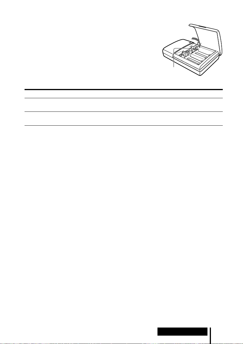
Cuando cargue pilas R03 (tamaño AAA)
Con el cargador de pilas suministrado también se
pueden cargar pilas Sony de níquel-cadmio R03
(tamaño AAA) (NC-AAA) y pilas de níquel-hydrium
R03 (tamaño AAA) (NH-AAA).
Cuando cargue pilas R03 (tamaño AAA), empuje
hacia abajo el regulador del cargador de pilas.
Cuando cargue pilas R6 (tamaño AA), suba el
regulador.
Regulador
Tiempos de carga para las pilas recargables R03 (tamaño AAA)
Tipo de pilas Tiempo de carga*
Pilas Sony de níquel-cadmio R03 (tamaño AAA)
NC-AAA (250 mAh)
Pilas Sony de níquel-hydrium R03 (tamaño AAA)
NH-AAA (650 mAh)
5 horas aprox.
10 horas aprox.
* Tiempo para cargar completamente las pilas cuando están totalmente agotadas.
Notas
• Con el cargador de pilas suministrado se pueden cargar pilas Sony de níquel-cadmio R6
(tamaño AA) (NC-AA, NC-AAS) y pilas Sony de níquel-hydrium R6 (tamaño AA) (NH-AA).
No intente nunca cargar otros tipos de pilas recargables ni pilas secas.
• No utilice pilas Sony de níquel-cadmio R6 (tamaño AA), NC-AA (HJ).
• Las pilas de níquel-cadmio deberán ser reemplazadas por otras nuevas cuando duren
solamente la mitad del tiempo esperado después de haberlas cargado completamente. Compre
pilas Sony de níquel-cadmio R6 (tamaño AA) (NC-AA, NC-AAS) o pilas Sony de níquel-
hydrium R6 (tamaño AA) (NH-AA). Usted podrá adquirir las pilas en el comercio donde haya
comprado el sistema o en el distribuidor Sony más cercano.
• Algunos tipos de pilas podrán no estar disponibles en algunas zonas.
Funcionamiento
19
ES
Page 80

Escucha del sonido del componente conectado
Antes de comenzar la operación, asegúrese de haber leído
“Conexión del sistema de auriculares” y de haber realizado
las conexiones apropiadas.
1 Encienda el componente conectado al procesador envolvente digital.
Reproductor DVD u otro
componente de audio y
vídeo
POWER
2 Presione POWER para encender el procesador envolvente digital.
El indicador POWER se encenderá en verde.
POWER
3 Póngase los auriculares.
El indicador POWER se encenderá en rojo, y los auriculares se encenderán
automáticamente.
20
ES
Funcionamiento
Indicador
POWER
BALANCE
P
O
W
E
R
VOL
Page 81

4 Presione INPUT para seleccionar el componente que quiera escuchar.
DIGITAL
ANALOG
INPUT
Luz del indicador Fuente de sonido seleccionada
DIGITAL Sonido del componente conectado a la toma DIGITAL IN
ANALOG Sonido del componente conectado a las tomas LINE INPUT
Nota
Para escuchar fuentes de sonido de audio doble (MAIN/SUB), conecte a las tomas LINE
INPUT, y después seleccione la fuente de sonido que quiera escuchar en el reproductor,
televisor, u otro componente.
5 Presione OUTPUT para seleccionar el modo de salida (efecto envolvente)
(consulte la página 22).
DECODE MODE
DECODE MODE
DOLBY DIGITAL
DOLBY DIGITAL
DOLBY SURROUND
DOLBY SURROUND
DTS
L
L
LS
LS
C
C
VIRTUAL
OUTPUT
OUTPUT
R
R
RS
RS
Funcionamiento
(continúa)
21
ES
Page 82

Luz del indicador Modo de salida (efecto envolvente)
DECODE MODE
DECODE MODE
DOLBY DIGITAL
DOLBY DIGITAL
DOLBY SURROUND
DOLBY SURROUND
DTS
C
C
L
L
LS
LS
VIRTUAL
RS
RS
R
R
OFF
Reproducción normal de los auriculares.
DECODE MODE
DECODE MODE
DOLBY DIGITAL
DOLBY DIGITAL
DOLBY SURROUND
DOLBY SURROUND
DTS
C
C
L
L
LS
LS
VIRTUAL
R
R
RS
RS
VIRTUAL FRONT
Efecto virtual en el que el sonido parece provenir de dos altavoces
(derecho e izquierdo) situados enfrente de usted.
VIRTUAL SURROUND
Efecto envolvente virtual en el que el sonido parece provenir no
DECODE MODE
DECODE MODE
DOLBY DIGITAL
DOLBY DIGITAL
DOLBY SURROUND
DOLBY SURROUND
DTS
C
C
L
L
LS
LS
VIRTUAL
RS
RS
R
R
solamente de dos altavoces delanteros (derecho e izquierdo), sino
también de un altavoz central, dos traseros (derecho e izquierdo), y
un subwoofer (cuando está encendido DOLBY DIGITAL y DTS).
El procesador envolvente digital identifica y procesa
automáticamente de acuerdo con el formato de la señal de entrada
de audio.
Cuando está encendido el indicador DOLBY DIGITAL: Se está
procesando audio grabado en el formato Dolby Digital 5.1 ch.
Cuando está encendido el indicador DOLBY SURROUND: Se está
procesando audio grabado en el formato Dolby Surround (Pro
Logic).
Cuando el indicador DTS está encendido: Se está procesando audio
grabado en el formato DTS 5.1 ch.
Notas
• El procesador reconoce automáticamente el modo de decodificación (DOLBY DIGITAL/
DOLBY SURROUND/DTS), y la luz del indicador correspondiente se encenderá.
Seleccione audio Dolby Digital o DTS para la salida de audio en el reproductor
conectado.
• El modo de decodificación se volverá DOLBY SURROUND en los casos siguientes.
– Cuando la señal recibida por la entrada digital sea PCM
– Durante entrada analógica
22
ES
Funcionamiento
Page 83

6 Presione EFFECT para seleccionar el campo de sonido deseado.
CINEMA
MUSIC
EFFECT
Luz del indicador Campo de sonido y fuente de sonido apropiada
CINEMA Modo que reproduce el campo de sonido de una sala de cine.
Este modo es apropiado para fuentes de sonido de películas.
MUSIC Modo que reproduce el campo de sonido de una habitación de
escucha con buen ambiente acústico.
Este modo es apropiado para fuentes musicales.
Nota
Si el modo de salida (efecto sonoro) está ajustado en “OFF” en el paso 5 de la página 21, no
podrá seleccionar un campo de sonido aunque presione EFFECT.
7 Ajuste el volumen.
Para subir
el volumen
Para bajar
el volumen
BALANCE
P
O
W
E
R
VOL
Para ajustar el volumen de auriculares (vendidos por separado) conectados a
la toma PHONES
Gire PHONES—LEVEL para ajustar el volumen.
MIN
LEVEL
Para subir
el volumen
MAX
PHONES
Para bajar
el volumen
Nota
Cuando vea películas, tenga cuidado de no subir el volumen demasiado en escenas
silenciosas. Podría dañar sus oídos cuando se reproduzca una escena ruidosa.
(continúa)
Funcionamiento
23
ES
Page 84

8 Ajuste el balance.
Se vuelve más
alto el lado
derecho.
Se vuelve más
alto el lado
izquierdo.
BALANCE
P
O
W
E
R
VOL
Los auriculares se apagan automáticamente al quitárselos
— Función de conexión/desconexión automática de la alimentación
Cuando no esté utilizando los auriculares,
asegúrese de que la banda autoajustable no esté
subida. Si la banda autoajustable está subida se
Banda
autoajustable
mantendrá conectada la alimentación.
Para comprobar la energía restante en las pilas
Suba la banda autoajustable y compruebe
el indicador POWER. Las pilas podrán
utilizarse cuando el indicador POWER se
encienda en rojo. Si la luz del indicador
POWER se debilita, el sonido se
distorsiona o aumenta el ruido, cargue las
pilas o utilice pilas secas.
Indicador
POWER
Después de utilizar el sistema de auriculares
Apague el procesador envolvente digital antes de apagar el componente que se
encuentre conectado al mismo. Si apaga primero el componente conectado, se cortará
el rayo infrarrojo y podrá emitirse ruido (esto no es un defecto de funcionamiento).
No cuelgue los auriculares en el procesador envolvente digital ni en otro componente.
La función de conexión automática de la alimentación podría activarse
inadvertidamente y se consumirían las pilas.
Tiempo de transición entre modos
Cuando se presionan botones en el procesador envolvente digital para cambiar a
nuevos modos, el tiempo de transición entre modos puede variar. Esto se debe a
diferencias en la transmisión de programas entre modos.
Función de enmudecimiento
La función de enmudecimiento se activará automáticamente interrumpiendo el
sonido de salida por los auriculares siempre que éstos salgan fuera del área de
transmisión de infrarrojos o cuando se interrumpa el rayo infrarrojo. La función de
enmudecimiento se cancelará automáticamente cuando se aproxime al procesador
envolvente digital o ya no haya nada que se interponga en la trayectoria del rayo
infrarrojo.
ES
24
Funcionamiento
Page 85

Área de transmisión de infrarrojos
La ilustración de abajo muestra el área aproximada de transmisión de infrarrojos
desde el procesador envolvente digital.
Rayos infrarrojos
4 m
aprox.
Procesador envolvente
digital
4 m
aprox.
Notas
• Como este sistema utiliza rayos infrarrojos, podrá aumentar el ruido eléctrico (ruidos de
silbido) a medida que los auriculares sean alejados del procesador envolvente digital, aunque
los mismos se encuentren dentro del área de transmisión mostrada en la ilustración de arriba.
Además, si se bloquean los rayos infrarrojos, se podrá interrumpir el sonido o escucharse
ruido. Esto se debe a las características de los rayos infrarrojos y no a un defecto de
funcionamiento.
• No cubra el sensor de rayos infrarrojos con la mano ni con el cabello.
• En tanto que los auriculares se encuentren dentro del área de transmisión mostrada en la
ilustración de arriba, podrá orientarlos en cualquier dirección en relación con el procesador
envolvente digital (hacia el frente, girados a 90°, o girados a 180°).
• El sonido podrá variar dependiendo de la posición y condiciones del procesador envolvente
digital en la habitación. Se recomienda que coloque el procesador envolvente digital en el
lugar que ofrezca el sonido más claro posible.
• Si utiliza el procesador envolvente digital con otros procesadores o transmisores podrá ocurrir
que las señales se mezclen.
45°
45°
10 m
aprox.
(continúa)
Funcionamiento
25
ES
Page 86

Cómo colocar la tapa de las pilas cuando se haya quitado
Alinee A con A, y B con B, como se muestra en la ilustración y después coloque la
tapa en posición.
A
B
B
A
Si no entra ninguna señal de audio durante 10 minutos
La emisión de rayos infrarrojos desde el procesador envolvente digital cesará
automáticamente cuando no haya entrada de audio durante 10 minutos. Los rayos
infrarrojos se emitirán automáticamente otra vez cuando vuelva a entrar una señal de
audio. Cuando la entrada sea analógica, la emisión de rayos infrarrojos podrá
interrumpirse cuando se emita un sonido extremadamente bajo durante unos 10
minutos. Si se diera el caso, suba el volumen del componente de audio y vídeo
conectado y baje el volumen de los auriculares.
Notas
• Podrá haber diferencia de brillo en el transmisor de infrarrojos del procesador envolvente
digital. Sin embargo, esto no afectará al área de transmisión.
• Los auriculares deberán utilizarse dentro del área de transmisión de infrarrojos (consulte
“Área de transmisión de infrarrojos” en la página 25).
• No utilice el procesador envolvente digital en lugares expuestos a la luz solar directa ni a una
luz intensa. El sonido podría interrumpirse.
• Estos auriculares tipo abierto están diseñados de forma que el sonido pueda fluir también al
exterior de los mismos. Tenga cuidado de no subir mucho el volumen como para molestar a
otras personas alrededor a usted.
• Utilice un nivel de volumen adecuado para no dañar sus oídos y para asegurarse de que
todavía puede escuchar los sonidos alrededor de usted.
• El efecto de sonido envolvente podrá no obtenerse cuando la fuente de sonido no incorpore
vídeo, tal como CDs de música.
• Este sistema simula el HRTF* para una persona corriente. Sin embargo, el efecto podrá variar
de una persona a otra porque la función HRTF puede variar entre individuos.
* Head Related Transfer Function (Función de transferencia vinculada a la cabeza)
ES
26
Funcionamiento
Page 87

Auriculares adicionales
A este sistema se pueden añadir auriculares de una de dos formas.
Para disfrutar del sonido envolvente más de una persona utilizando auriculares
inalámbricos
t Utilizando auriculares inalámbricos por infrarrojos MDR-IF5000 adicionales
(vendidos por separado), podrá disfrutar de la experiencia del sonido envolvente
más de una persona al mismo tiempo.
* No hay límite en cuanto al número de auriculares que pueden utilizarse dentro
del área de transmisión por infrarrojos.
Procesador envolvente
digital
Para disfrutar de una mayor calidad de sonido
t La toma PHONES está ajustada para los auriculares alámbricos de tipo
completamente abierto MDR-F1 (vendidos por separado), por lo que si conecta los
MDR-F1 podrá disfrutar de un sonido envolvente de gran calidad. También puede
utilizar cualquier tipo de auriculares alámbricos abiertos con este sistema.
Para obtener un efecto envolvente suficiente, se recomienda utilizar los auriculares
estéreo inalámbricos MDR-IF5000 o los auriculares alámbricos de tipo
completamente abiertos MDR-F1.
Procesador envolvente
digital
MDR-IF5000 (vendidos por separado)
Auriculares alámbricos de tipo completamente
abierto MDR-F1 (vendidos por separado) u
otros auriculares alámbricos abiertos.
A la toma PHONES
Notas
• Cuando desenchufe los auriculares de la toma PHONES, agarre siempre por la clavija. No tire
nunca del propio cable.
• Cuando se utilicen auriculares cerrados y auriculares para insertar en el oído tal vez no pueda
obtenerse el efecto envolvente.
Funcionamiento
27
ES
Page 88

¡ Información adicional
Solución de problemas
Si se encuentra con algún problema al usar este sistema de auriculares, utilice la lista
de comprobación siguiente.
Si el problema persistiera, consulte al distribuidor Sony más cercano.
Síntoma Causa y remedio
No hay sonido
(ambos canales o un
canal)
Sonido distorsionado
/ Encienda el procesador envolvente digital.
/ Compruebe que el componente de AV y el adaptador de alimentación de CA
estén conectados al procesador envolvente digital y que estén enchufados a
una toma de corriente de la pared.
/ Encienda el componente de AV conectado al procesador envolvente digital,
y comience el programa (la reproducción).
/ Utilice el botón INPUT para comprobar si el componente AV que quiera
escuchar está debidamente seleccionado.
/ Si la toma de auriculares del componente de AV está conectada al
procesador envolvente digital, suba el nivel de volumen del componente de
AV conectado.
/ Suba el volumen de los auriculares.
/ Compruebe la posición del control BALANCE de los auriculares.
/ Está activada la función de enmudecimiento.
• Compruebe que no haya nada bloqueando la trayectoria desde el
procesador envolvente digital hasta los auriculares.
• Intente utilizar los auriculares lo más cerca posible del procesador
envolvente digital.
• Cambie la posición o el ángulo del procesador envolvente digital.
/ La luz del indicador POWER de los auriculares es débil o está apagada. Esto
indica que la pila tiene poca energía. Si está utilizando pilas recargables,
cargue las pilas. Si está utilizando pilas secas, reemplácelas por otras nuevas.
Si el indicador sigue apagado, consulte al distribuidor Sony más cercano.
/ Está intentando reproducir una canción de audio DTS en un reproductor
DVD que no soporta DTS.
Utilice un reproductor DVD que soporte DTS, o bien seleccione una canción
de audio Dolby Digital o PCM.
/ Ponga el conmutador ATT (atenuador) del procesador envolvente digital en
“–8dB”.
/ La luz del indicador POWER de los auriculares es débil o está apagada. Esto
indica que la pila tiene poca energía. Si está utilizando pilas recargables,
cargue las pilas. Si está utilizando pilas secas, reemplácelas por otras nuevas.
Si el indicador sigue apagado, consulte al distribuidor Sony más cercano.
/ Si la toma de auriculares del componente de AV está conectada al
procesador envolvente digital, baje el nivel de volumen del componente de
AV conectado.
/ Cuando utilice fuentes de audio DTS, ponga el modo de salida del
procesador en VIRTUAL SURROUND (página 23).
28
ES
Información adicional
Page 89

Síntoma Causa y remedio
Alto nivel de ruido/
Sonido bajo
No se obtiene el
efecto de sonido
envolvente
El indicador
DOLBY DIGITAL
no se enciende
La luz del indicador
DTS no se enciende
Las pilas no se
pueden cargar
/ Utilice los auriculares cerca del procesador envolvente digital. El ruido
aumentará a medida que los auriculares se alejen del procesador envolvente
digital. Esto se debe a las características de los rayos infrarrojos y no a un
defecto de funcionamiento.
/ Compruebe que no haya nada bloqueando la trayectoria desde el procesador
envolvente digital hasta los auriculares.
/ Compruebe que su mano o cabello no esté cubriendo el sensor de infrarrojos
de los auriculares.
/ Si está entrando luz solar directamente a la habitación por una ventana
cercana al procesador envolvente digital o a los auriculares, eche las cortinas
o cierre la persiana para impedir la entrada de luz solar directa. O, póngase
en un lugar no expuesto a la luz solar directa.
/ Cambie la posición o el ángulo del procesador envolvente digital.
/ Ponga el conmutador ATT (atenuador) del procesador envolvente digital en
“0dB”.
/ La luz del indicador POWER de los auriculares es débil o está apagada. Esto
indica que la pila tiene poca energía. Si está utilizando pilas recargables,
cargue las pilas. Si está utilizando pilas secas, reemplácelas por otras nuevas.
Si el indicador sigue apagado, consulte al distribuidor Sony más cercano.
/ Si la toma de auriculares del componente de AV está conectada al
procesador envolvente digital, suba el nivel de volumen del componente de
AV conectado.
/ Presione el botón OUTPUT para seleccionar el modo VIRTUAL
SURROUND (página 23).
/ El audio de la parte que está siendo reproducida no es una señal multicanal.
El efecto envolvente no funciona con fuentes monoaurales y otras fuentes de
sonido que no hayan sido procesadas para sonido envolvente.
/ El ajuste de la salida digital de audio para el reproductor DVD tal vez esté
puesto en “PCM”. Consulte el manual de instrucciones suministrado con el
reproductor DVD, y cambie al ajuste (tal como “Dolby Digital/PCM” o
“Dolby Digital”) que sirva para usar con componentes que tengan
incorporados decodificadores Dolby Digital (AC-3).
/ Esta intentando reproducir software DVD que no es compatible con Dolby
Digital 5.1 ch.
/ El audio de la parte que está siendo reproducida no es una señal multicanal.
/ El ajuste de salida digital DTS en el reproductor DVD está puesta en OFF.
Consulte el manual de instrucciones suministrado con el reproductor DVD,
y ponga el ajuste de salida digital DTS en ON.
/
Esta intentando reproducir software DVD que no es compatible con el formato DTS.
/ El audio del capítulo que está reproduciendo no es DTS.
/ El reproductor DVD no soporta el formato DTS.
Utilice un reproductor DVD que soporte DTS.
/ Está utilizando pilas secas.
Inserte las pilas recargables suministradas u opcionales (página 10).
/
Está utilizando pilas recargables diferentes a las suministradas o a las opcionales.
Inserte las pilas recargables suministradas u opcionales (página 10).
Información adicional
29
ES
Page 90

Precauciones
Sobre seguridad
• No deje caer, golpee, ni exponga a golpes
fuertes de ningún otro tipo el procesador
envolvente digital ni los auriculares. Ello
podría dañar el producto.
• No desarme ni intente abrir ninguna parte
del sistema.
Sobre fuentes de alimentación y
ubicación
• Si no va a utilizar el sistema durante largo
tiempo, desenchufe el cable del adaptador
de alimentación de CA de la toma de
corriente. Para desenchufar el cable,
agárrelo por la clavija. No tire del propio
cable.
• No coloque el sistema en ninguno de los
lugares siguientes.
– Lugar expuesto a la luz solar directa,
cerca de una estufa, ni en ningún otro
lugar de temperatura extremadamente
alta
– Lugar polvoriento
– Sobre una superficie inestable o inclinada
– Lugar expuesto a muchas vibraciones
– Baño o otros lugares muy húmedos
Sobre los auriculares
Para proteger sus oídos
El escuchar el sonido a alto volumen durante
largos periodos de tiempo podrá dañar sus
oídos. Para proteger sus oídos, no escuche
con el volumen demasiado alto.
Actúe consideradamente
Cuando el volumen es muy alto, el sonido
fluye al exterior de los auriculares. Tenga
cuidado de no subir el volumen tan alto como
para que pueda molestar a las personas
alrededor de usted.
Hay cierta tendencia a subir el volumen
cuando se utiliza en lugares con ruido. Sin
embargo, el volumen deberá mantenerse a un
nivel que usted pueda responder en caso de
que alguien le llame mientras esté
escuchando con los auriculares.
Sobre las almohadillas de los oídos
Las almohadillas de los oídos podrán
desgastarse después de largos periodos de
uso y de almacenamiento. Para reemplazar
las almohadillas de los oídos, consulte al
distribuidor Sony más cercano.
Sobre limpieza
Utilice un paño suave ligeramente
humedecido con una solución de detergente
suave. No utilice disolventes tales como
diluyentes, bencina ni alcohol porque podrán
dañar la superficie.
Cuando se averíe el producto
• Cuando se averíe el producto, o si entrase
algún objeto extraño en la unidad,
desconecte inmediatamente la alimentación
y póngase en contacto con el distribuidor
Sony más cercano.
• Cuando lleve el sistema a un distribuidor
Sony, asegúrese de llevar los auriculares y
el procesador envolvente digital.
30
ES
Información adicional
Page 91

Especificaciones
Procesador envolvente digital
(DP-IF5100)
Funciones del decodificador
Dolby Digital 5.1 ch y
2ch
Dolby Pro Logic
DTS
Función de sonido virtual
OFF
Virtual delantero
Virtual envolvente
Sistema de modulación
Modulación de
frecuencia
Frecuencia de onda transportadora
Canal derecho 2,8 MHz
Canal izquierdo 2,3 MHz
Distancia de transmisión
Aprox. 10 m hasta el lado
delantero
Gama de transmisión 20 – 20.000 Hz
Razón de distorsión 1% o menos (1 kHz)
Entradas de audio Entrada óptica (tipo
rectangular) × 1
Entrada analógica
(enchufe macho
izquierdo/derecho) × 1
Alimentación 9 V CC (del adaptador
de alimentación de CA
suministrado)
Dimensiones (an/al/prf)
Aprox. 85 × 190 ×
180 mm
Peso Aprox. 1,0 kg
(1.000 g)
Auriculares estéreo inalámbricos
(MDR-IF5000)
Gama de la frecuencia de reproducción
12 – 24.000 Hz
Alimentación Pilas de níquel-cadmio
recargables
(suministradas) o pilas
secas R6 (tamaño AA) o
recargables (vendidas
por separado)
Peso Aprox. 280 g (incluyendo
las pilas de níquel-
cadmio recargables
suministradas)
Accesorios suministrados
Soporte para el procesador
envolvente digital (1)
Adaptador de alimentación de
CA (9 V) (1)
Pilas de níquel-cadmio
recargables (NC-AA) (2)
Cargador de pilas (1)
Clavija de carga para el
cargador de pilas (1) (Solo las
versiones* CED, CEK, HK4 y
E13)
Cable de conexión digital
óptico (clavija rectangular ˜
clavija rectangular, 1,5 m) (1)
Manual de instrucciones (1)
Información sobre el producto
(1)
Accesorios recomendados
Cables de conexión RK-C310, RK-C315,
RK-C320, RK-C330
(enchufe macho × 2
˜ enchufe macho
× 2)
RK-G129 (miniclavija
estéreo ˜ enchufe
macho × 2)
Selector digital óptico SB-D30
Cable de conexión digital óptico
POC-5A, POC-10A,
POC-15A (clavija
óptica rectangular ˜
clavija óptica
rectangular)
POC-5AB, POC-10AB,
POC-15AB (clavija
óptica rectangular ˜
miniclavija óptica)
El diseño y las especificaciones están sujetos a
cambio sin previo aviso.
* La clavija de carga suministrada con este
sistema varía dependiendo de la versión del
sistema. Para comprobar la versión,
consulte el código de versión impreso en la
caja.
Información adicional
31
ES
Page 92

32
ES
Información adicional
Printed in Korea
 Loading...