


MDP-V90K
MDP-V90K
RMT-M47A
SERVICE MANUAL
Photo : GOLD
Model Name Using Similar Mechanism MDP-V1
Optical Pick-up Type KHS-150A
SPECIFICATIONS
E Model
Chinese Model
9-920-971-11
Sony Corporation
Home A&V Products Company
— 224 —
Printed in Japan © 1997. 8
97H0921-1
Published by General Engineering Dept.
(Shibaura)
VIDEO CD/CD/LD PLAYER
MICROFILM

MODEL IDENTIFICATION
— BACK PANEL —
Parts No.
Parts No.
3-971-070-4
3-971-070-5
Model
E, Hong Kong model
Chinese model
— 2 —

CAUTION
Use of controls or adjustments or performance of procedures
other than those specified herein may result in hazardous radiation exposure.
Notes on chip component replacement
• Never reuse a disconnected chip component.
• Notice that the minus side of a tantalum capacitor may be
damaged by heat.
SAFETY-RELATED COMPONENT WARNING !!
COMPONENTS IDENTIFIED BY MARK ! OR DO TTED LINE
WITH MARK ! ON THE SCHEMATIC DIAGRAMS AND IN
THE PARTS LIST ARE CRITICAL TO SAFE OPERATION.
REPLACE THESE COMPONENTS WITH SONY PARTS
WHOSE PART NUMBERS APPEAR AS SHOWN IN THIS
MANUAL OR IN SUPPLEMENTS PUBLISHED BY SONY.
— 3 —

SERVICING NOTE
TABLE OF CONTENTS
SELF-DIAGNOSIS
This model has the self-diagnosis function for the video and audio
decoder sections.
Immediately after the power on, the self-diagnosis function searches
each operation of IC’s around the mode microcomputer (IC305).
The LED (D301) on the VX-97 board indicates their results.
LED (D301) INDICATION
Light
1 time blinking (Repeatedly)
[VX-97 BOARD] — SIDE B —
IC301
IC305
D301
SYMPTOM
No error
Transmission error between
IC305 and IC101.
1. GENERAL
Index to parts and controls ........................................................1-1
Playing a disc ............................................................................1-2
Playing karaoke .........................................................................1-3
Playing a VIDEO CD using PBC functions (PBC Playback) ...1-4
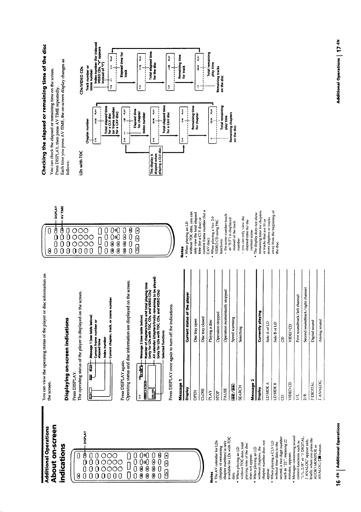
About on-screen indications ......................................................1-5
Selecting a chapter or track directly (Chapter/Track Search)....1-6
Searching by frame, time, or scene number
(Frame/ Time/Scene Search) .....................................................1-6
Searching for a particular point on a disc ..................................1-7
Locating by observing several scenes at one time
(Digest Play) ............................................................................1-8
Viewing Frame-by-frame action................................................1-9
Resuming LD/VIDEO CD playback (Auto Resume) ...............1-9
Playing a section repeatedly (Repeat Play) .............................1-10
Playing songs in random order (Shuffle Play).........................1-11
Playing songs in any order you like (Program Play) ...............1-12
Playing a disc within a specified period of time
(Auto Program Play)................................................................1-12
Using the sound control functions ...........................................1-13
Reducing Distortion of the Picture
(DNR: Digital Noise Reduction) .............................................1-14
Selecting karaoke song order (Reserve) ..................................1-14
Using karaoke functions ..........................................................1-16
2. DISASSEMBLY
2-1. Opening of MB-97/VX-97 Board (Service Position) ........2-1
2-2. Front panel Assembly ........................................................2-1
2-3. Disc Tray Assembly ...........................................................2-2
2-4. Chucking Block Assembly.................................................2-2
2-5. Frame (L, R) Assembly......................................................2-3
2-6. Mounting the Frame (R) Assembly....................................2-3
2-7. Control Gear and Loading Motor Assembly......................2-4
2-8. Mounting the Control Gear ................................................2-4
2-9. Feed Base Block Assembly................................................2-5
2-10. Mounting the Feed Base Block Assembly .......................2-6
2-11. Height Adjustment of the Turntable Assembly ................2-7
2-12. Optical Pick-up Block (KHS-150A)
Disassembly I
(Optical Pick-up Block Motor Operates) .........................2-7
Disassembly II
(Optical Pick-up Block Motor Operates) .........................2-8
Disassembly III
(Optical Pick-up Block Motor Doesn’t Operate) .............2-8
2-13. Mounting the Optical Pick-up Block Assembly ..............2-9
2-14. Circuit Boards Location .................................................2-10
— 4 —

3. BLOCK DIAGRAMS
7. ADJUSTMENTS
3-1. Overall (1/3) Block Diagram .............................................3-1
3-2. Overall (2/3) Block Diagram .............................................3-3
3-3. Overall (3/3) Block Diagram .............................................3-5
3-4. Video (1/2) Block Diagram................................................3-7
3-5. Video (2/2) Block Diagram................................................3-9
3-6. Servo (1/2) Block Diagram ..............................................3-11
3-7. Servo (2/2) Block Diagram ..............................................3-13
3-8. System Control (1/2) Block Diagram ..............................3-15
3-9. System Control (2/2) Block Diagram ..............................3-17
3-10. Mode Control Block Diagram........................................3-19
3-11. Audio (1/2) Block Diagram............................................3-21
3-12. Audio (2/2) Block Diagram............................................3-23
3-13. Video CD (1/2) Block Diagram......................................3-25
3-14. Video CD (2/2) Block Diagram......................................3-27
3-15. Power Block Diagram ....................................................3-29
4. PRINTED WIRING BOARDS AND SCHEMATIC
DIAGRAMS
4-1. Frame Schematic Diagram.................................................4-1
4-2. Printed Wiring Boards and Schematic Diagrams ...............4-5
• MB-97 (Video, Servo, System Control, Audio) Board ...4-7
• MB-97 (Video) Board ...................................................4-11
• MB-97 (Servo, System Control) Board ........................4-16
• MB-97 (Audio) Board ..................................................4-21
• VX-97 Board ................................................................4-25
• FP-1090 Board ..............................................................4-33
• PW-1090, SW-1090A, SW1090B Boards ....................4-40
• YC-97 Board .................................................................4-46
• HP-97 Board .................................................................4-49
• AX-97, MA-1090 Boards .............................................4-51
• FG-42, IB-10, MD-67, MT-59, SW-278 Boards ..........4-57
• PS-97, ST-1090 Boards.................................................4-64
7-1. List of Servicing Jigs .........................................................7-1
7-2. Caution on Adjustment ......................................................7-1
7-3. Power Block Check............................................................ 7-1
7-3-1. Power Supply Check (PS-97 board) ............................ 7-1
7-4. System Control System Adjustment ..................................7-1
7-4-1. Microprocessor Clock Adjustment (MB-97 board) .....7-1
7-5. Adjustment After the Attachment of the Optical Pick-up
Block .................................................................................7-2
7-5-1. Jigs and Tools ..............................................................7-2
7-5-2. CD Adjustment ............................................................ 7-2
7-6. Servo System Adjustments ................................................7-4
7-6-1. LD Side A Adjustment.................................................7-4
7-6-2. LD Side B Adjustment................................................. 7-5
7-7. Video System Adjustments ................................................7-6
7-7-1. LD Output Level Adjustment (MB-97 board).............7-6
7-7-2. Video Clock Adjustment (VX-97 board).....................7-6
7-7-3. Video CD Output Level Adjustment
(VX-97 board) .............................................................7-6
7-8. Arrangement Diagram For Adjustment Parts..................... 7-8
8. EVALUATION OF OPTICAL PICK-UP BLOCK
(KHS-150A)
8-1. Preparation ........................................................................8-1
8-2. RF Level Check ................................................................. 8-1
8-3. Tracking Level/Tracking Balance Check...........................8-1
8-4. Crosstalk Check .................................................................8-1
9. INSTRUCTION MANUAL FOR SPECIAL
FUNCTIONS
(For the contents of section 9, refer to page 9-1.)
...................................................................9-1
5. REPAIR PARTS LIST
5-1. Exploded Views .................................................................5-1
5-1-1. Upper Case and Front Panel Section ...........................5-1
5-1-2. Main Chassis Section (1).............................................5-2
5-1-3. Main Chassis Section (2).............................................5-3
5-1-4. Frame (L, R) Section ...................................................5-4
5-1-5. Mechanism Deck Section ............................................5-5
5-2. Electrical Parts List ...........................................................5-6
6. IC PIN DESCRIPTION
6-1. Mode Control IC Pin Description
(FP-1090 Board IC102 HD6433712-C41H)...................... 6-1
6-2. VCD Mode Control IC Pin Description
(VX-97 Board IC305 HD6413002F10) .............................6-2
6-3. System Control IC Pin Description
(MB-97 Board IC501 MB89094PF-G-154-BND).............6-4
6-4. System Control IC Pin Description
(MB-97 Board IC502 LC21011B-X78).............................6-6
— 5 —

MDP-V90K
SECTION 1
GENERAL
This section is extracted from
instruction manual.
1-1

1-2

1-3

1-4
1-5

1-6

1-7

1-8

1-9

1-10

1-11

1-12

1-13

1-14

1-15

1-16

1-17

1-18
1-18E

SECTION 2
)
DISASSEMBLY
Note: Follow the disassembly procedure in the numerical order given.
2-1. OPENING OF MB-97/VX-97 BOARD (SERVICE POSITION)
5
1
Remove the case.
Open the MB-97/VX-97 board
in the arrow direction.
MDP-V90K
2
Two screws
(Tapping screw)
3
Two screws
(BV SUMITITE (B3)
4
Two screws
(BVTP 3 x 8)
2-2. FRONT PANEL ASSEMBLY
1
Remove the case.
!¡
Remove the claws (6 portion).
2
Two screws
(+B 3 x 4)
Door assembly
Two claws
!™
Front panel assembly
Two claws
9
Two screws
(Tapping screw)
6
Connector (CN401)
4
Two screws
(Tapping screw)
5
!£
Flat cable
(CN101)
!¢
Flat cable
(CN102)
Two wires
8
Connector (CN102)
3
Door assembly
2-1
Two claws
0
Two screws
(Tapping screw)
7
Connector (CN951)

2-3. DISC TRAY ASSEMBLY
r
Tray link shaft assembly
2
Two claws
Note on installation:
Insert it with fitting to the guide
roller and fit its gear to portion
of tray link shaft assembly.
3
Disc tray assembly
Cut portion
Guide roller
2-4. CHUCKING BLOCK ASSEMBLY
1
Open the MB-97/VX-97 board in the arrow direction.
Guide roller
A
1
Turn the pulley in the
direction of arrow
A
.
8
Chucking block
assembly
2
6
Reinforcement
stay assembly
Screw (BVTP 3 x 8)
3
Screw (BVTP 3 x 8)
4
Bracket
5
Screw (BVTP 3 x 8)
7
Screw (BVTP 3 x 6)
9
Chuck plate holde
2-2

2-5. FRAME (L, R) ASSEMBLY
1
Two screws
(Tapping screw)
8
Two screws
(Tapping screw)
3
Two screws
(Tapping screw)
5
Tray link shaft
assembly
7
Flat cable
(CN301)
2
Front stay
4
Frame (L) assembly
9
Frame (R) assembly
6
Link shaft assembly
Note on installation:
Apply the grease on the area marked with
(2 portions).
(Grease: Molykote Grease EM-30LG
Part No. J-6090-014-A)
0
Tilt link shaft assembly
Note on installation:
Refer to the 2-10.
2-6. MOUNTING THE FRAME (R) ASSEMBLY
Note: Follow the assembly procedure in the numerical order given.
6
Setting the rib at the position
shown as the Fig-B.
Rib
Fig-B
*
Fig-A
2
Confirm that * screw is at the
position shown as the Fig-A.
7
Tray link shaft assembly
5
Apply the grease.
(Grease: Molykote Grease EM 30LG Part No. J-6090-014-A)
3
Two screws
(Tapping screw)
A
4
Frame (R) assembly
1
Turn the pulley in the
direction of arrow
A
.
2-3

2-7. CONTROL GEAR AND LOADING MOTOR ASSEMBLY
5
Loading motor assembly
2
Control gear
3
Belt
4
Two screws (M 3 x 2)
1
Screw (PTPWH 3 x 20)
2-8. MOUNTING THE CONTROL GEAR
Note: Follow the assembly procedure in the numerical order given.
2
Slider (R) knob
(Put aside in the direction of arrow.)
1
Tilt slider knob
(Put aside in the direction of arrow.)
3
Control gear
Note on installation:
(1) Apply the grease on the cam groove of control gear.
(Grease: Molykote Grease EM-30LG Part No. J-6090-014-A)
(2) Setting that marking at the postion shown as the figure.
4
Screw (PTPWH 3 x 20)
Marking
2-4

2-9. FEED BASE BLOCK ASSEMBLY
1
Remove the case.
2
Open the MB-97/VX-97 board.
3
Remove the chucking block assembly.
6
Two screws
(Tapping screw)
9
Flat cable (CN701)
!¡
Connector (CN203)
5
Two screws
(BV SUMITITE (B3))
7
Screw
(Tapping screw)
!™
Feed base block assembly
8
Flat cable (CN301)
!£
Tilt link shaft assembly
Disc tray assembly
A
0
Flat cable (CN503)
4
Rotate the pulley in the direction
of arrow
assembly.
A
, and eject the disc tray
2-5

2-10. MOUNTING THE FEED BASE BLOCK ASSEMBLY
Note: Follow the assembly procedure in the numerical order given.
2
Fix the feed base block assembly temporarily with three screws.
(BVTP 3 x 10)
9
Adjust feed base block assembly so that the Lissajous's waveform
goes to 0˚. (Tighten the screw completely.)
0
Refer to 7-5. Adjustment after the attachment of the optical pick-up block.
!¡
Two screws
(BV SUMITITE (B3))
Tilt disc
(Put aside in the
direction of arrow.)
4
Fig-B
1
Tilt link shaft assembly
Note on installation:
Setting the tilt slider and tilt disc
at the position shown as Fig-A, B.
Connector
(CN203)
8
Turn off
TRACKING and
SLED switches.
E
F
MD adjustment cable
6
Connect to the oscilloscope.
Oscilloscope
Lissajous's waveform
CH-1
CH-2
90˚ 0˚
180˚
5
Connect the connector
of MD adjustment cable
with the pattern face down.
(CN702)
7
Set the CD (YEDS-18) on the tray.
Press the PLAY (
·
) button and plays the track No. 1 PAUSE.
Tilt slider
(Put aside in the
direction of arrow.)
Fig-A
3
Three flat cable
(CN301, CN503, CN701)
2-6

2-11. HEIGHT ADJUSTMENT OF THE TURNTABLE ASSEMBLY
1
Remove the case.
2
Open the MB-97/VX-97 board.
3
Rotate the pulley on the right side of the set, and open the tray.
4
Remove the chucking block assembly and reinforcement stay assembly.
5
Change the turntable assembly.
Adjust the height and also the position putting in the reinforcement stay as below.
The thickness of the reinforcement is 1 mm.
6
Fix the reinforcement to fixed position.
Turntable assembly
Fixed screw
±
0.1 mm
37
FG ring
Put in the reinforcement stay between the spindle motor holder and
the FG ring, tighten the fixed screw hard after the height adjustment.
Reinforcement stay
1 mm
2-12. OPTICAL PICK-UP BLOCK (KHS-150A)
DISASSEMBLY I (OPTICAL PICK-UP BLOCK MOTOR OPERATES)
1
Set the service mode.
(1) Power is in STANDBY mode.
(2) Press the 1 button while pressing STOP (
(3) “No disc” will be appeared on the fluorescent indicator tube.
(4) Press the 10/0 button and then the 8 key of the remote control while pressing STOP (
on the unit.
(5) The display will be disappeared on the display board, then enter the test mode.
Note: As for the test mode, refer to the test mode on page 9-10.
2
Move the optical pick-up block to the upper front side (full of side B) pressing the SIDE-B button
continuously.
p
) button and 10 button on the unit.
3
Pull out plug from wall socket.
p
) button
5
Open the claws on
both side of housing
and remove flat cable.
Two claws
Housing
2-7
4
Pull out optical pick-up block with
hand in the arrow direction.