


MDP-V70K
RMT-M46A
SERVICE MANUAL
Model Name Using Similar Mechanism MDP-V1
Optical Pick-up Type KHS-150A
SPECIFICATIONS
E Model
Chinese Model
MICROFILM
VIDEO CD/CD/LD PLAYER
— 1 —

MODEL IDENTIFICATION
— BACK PANEL —
Parts No.
Parts No.
3-971-070-6
3-971-070-7
Model
E model
Chinese model
— 2 —

CAUTION
Use of controls or adjustments or performance of procedures
other than those specified herein may result in hazardous radiation exposure.
Notes on chip component replacement
• Never reuse a disconnected chip component.
• Notice that the minus side of a tantalum capacitor may be
damaged by heat.
SAFETY-RELATED COMPONENT WARNING !!
COMPONENTS IDENTIFIED BY MARK ! OR DO TTED LINE
WITH MARK ! ON THE SCHEMATIC DIAGRAMS AND IN
THE PARTS LIST ARE CRITICAL TO SAFE OPERATION.
REPLACE THESE COMPONENTS WITH SONY PARTS
WHOSE PART NUMBERS APPEAR AS SHOWN IN THIS
MANUAL OR IN SUPPLEMENTS PUBLISHED BY SONY.
— 3 —

SERVICING NOTE
TABLE OF CONTENTS
SELF-DIAGNOSIS
This model has the self-diagnosis function for the video and audio
decoder sections.
Immediately after the power on, the self-diagnosis function searches
each operation of IC’s around the mode microcomputer (IC305).
The LED (D301) on the VX-97 board indicates their results.
LED (D301) INDICATION
Light
1 time blinking (Repeatedly)
[VX-97 BOARD] — SIDE B —
IC301
IC305
D301
SYMPTOM
No error
Transmission error between
IC305 and IC101.
1. GENERAL
Index to parts and controls ........................................................1-1
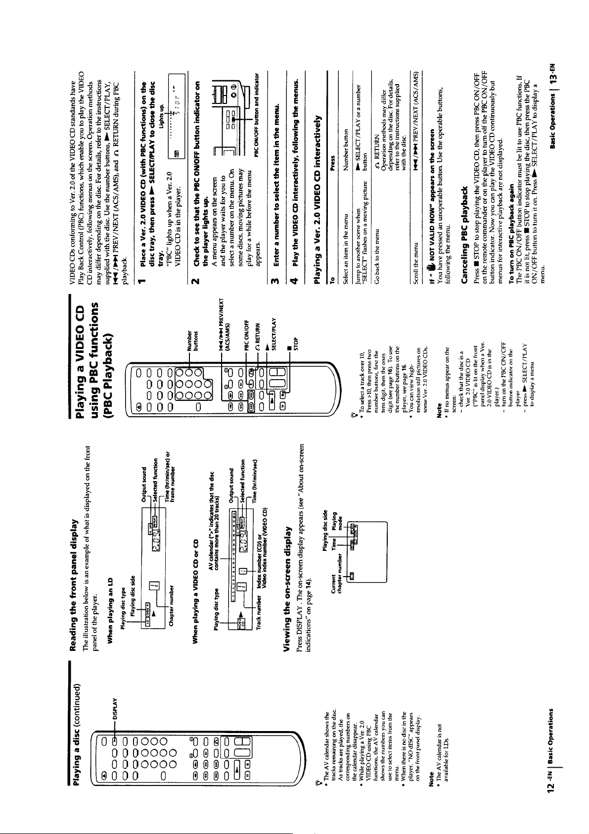
Playing a disc ............................................................................1-2
Playing a VIDEO CD using PBC functions (PBC Playback) ...1-3
About on-screen indications ......................................................1-4
Selecting a chapter or track directly (Chapter/Track Search)....1-5
Searching by frame, time, or scene number
(Frame/ Time/Scene Search) .....................................................1-5
Searching for a particular point on a disc .................................. 1-6
Locating by observing several scenes at one time
(Digest Play) ............................................................................1-7
Viewing Frame-by-frame action................................................1-8
Resuming LD/VIDEO CD playback (Auto Resume) ...............1-8
Playing a section repeatedly (Repeat Play) ...............................1-9
Playing songs in random order (Shuffle Play).........................1-10
Playing songs in any order you like (Program Play) ............... 1-11
Playing a disc within a specified period of time
(Auto Program Play)................................................................1-11
Using the sound control functions ...........................................1-12
Reducing Distortion of the Picture
(DNR: Digital Noise Reduction) .............................................1-13
Playing Karaoke ......................................................................1-13
2. DISASSEMBLY
2-1. Opening of MB-97/VX-97 Board (Service Position) ........2-1
2-2. Front Panel Assembly .......................................................2-1
2-3. Disc Tray Assembly ...........................................................2-2
2-4. Chucking Block Assembly.................................................2-2
2-5. Frame (L, R) Assembly......................................................2-3
2-6. Mounting the Frame (R) Assembly....................................2-3
2-7. Control Gear and Loading Motor Assembly......................2-4
2-8. Mounting the Control Gear ................................................2-4
2-9. Feed Base Block Assembly................................................2-5
2-10. Mounting the Feed Base Block Assembly .......................2-6
2-11. Height Adjustment of the Turntable Assembly ................2-7
2-12. Optical Pick-up Block (KHS-150A)
Disassembly I
(Optical Pick-up Block Motor Operates) .........................2-7
Disassembly II
(Optical Pick-up Block Motor Operates) .........................2-8
Disassembly III
(Optical Pick-up Block Motor Doesn’t Operate) ............. 2-8
2-13. Mounting the Optical Pick-up Block Assembly ..............2-9
2-14. Circuit Boards Location .................................................2-10
3. BLOCK DIAGRAMS
3-1. Overall (1/3) Block Diagram .............................................3-1
3-2. Overall (2/3) Block Diagram .............................................3-3
3-3. Overall (3/3) Block Diagram .............................................3-5
3-4. Video (1/2) Block Diagram................................................3-7
3-5. Video (2/2) Block Diagram................................................3-9
3-6. Servo (1/2) Block Diagram ..............................................3-11
3-7. Servo (2/2) Block Diagram ..............................................3-13
3-8. System Control (1/2) Block Diagram .............................. 3-15
3-9. System Control (2/2) Block Diagram .............................. 3-17
3-10. Mode Control Block Diagram........................................3-19
3-11. Audio (1/2) Block Diagram............................................3-21
3-12. Audio (2/2) Block Diagram............................................3-23
3-13. Video CD (1/2) Block Diagram......................................3-25
3-14. Video CD (2/2) Block Diagram......................................3-27
3-15. Power Block Diagram ....................................................3-29
— 4 —

4. PRINTED WIRING BOARDS AND SCHEMATIC
DIAGRAMS
8. EVALUATION OF OPTICAL PICK-UP BLOCK
(KHS-150A)
4-1. Frame Schematic Diagram ................................................. 4-1
4-2. Printed Wiring Boards and Schematic Diagrams ............... 4-5
• MB-97 (Video, Servo, System Control, Audio) Board...4-7
• MB-97 (Video) Board...................................................4-11
• MB-97 (Servo, System Control) Board ........................4-16
• MB-97 (Audio) Board .................................................. 4-21
• VX-97 Board ................................................................4-25
• FP-1090 Board .............................................................. 4-33
• PW-1090, SW-1090A, SW1090B Boards ....................4-40
• YC-97 Board.................................................................4-46
• HP-97 Board .................................................................4-49
• MA-1089 Board ............................................................ 4-51
• FG-42, IB-10, MD-67, MT-59, SW-278 Boards ..........4-53
• PS-97, ST1090 Boards..................................................4-60
5. REPAIR PARTS LIST
5-1. Exploded Views ................................................................. 5-1
5-1-1. Upper Case and Front Panel Section ...........................5-1
5-1-2. Main Chassis Section (1) .............................................5-2
5-1-3. Main Chassis Section (2) .............................................5-3
5-1-4. Frame (L, R) Section ...................................................5-4
5-1-5. Mechanism Deck Section ............................................5-5
5-2. Electrical Parts List ...........................................................5-6
6. IC PIN DESCRIPTION
8-1. Preparation ........................................................................8-1
8-2. RF Level Check .................................................................8-1
8-3. Tracking Level/Tracking Balance Check...........................8-1
8-4. Crosstalk Check .................................................................8-1
9. INSTRUCTION MANUAL FOR SPECIAL
FUNCTIONS
(For the contents of section 9, refer to page 9-1.)
...................................................................9-1
6-1. Mode Control IC Pin Description
(FP-1090 Board IC102 HD6433712-C41H)......................6-1
6-2. VCD Mode Control IC Pin Description
(VX-97 Board IC305 HD6413002F10) .............................6-2
6-3. System Control IC Pin Description
(MB-97 Board IC501 MB89094PF-G-154-BND).............6-4
6-4. System Control IC Pin Description
(MB-97 Board IC502 LC21011B-X78).............................6-6
7. ADJUSTMENTS
7-1. List of Servicing Jigs .........................................................7-1
7-2. Caution on Adjustment ......................................................7-1
7-3. Power Block Check............................................................7-1
7-3-1. Power Supply Check (PS-97 board) ............................7-1
7-4. System Control System Adjustment ..................................7-1
7-4-1. Microprocessor Clock Adjustment (MB-97 board).....7-1
7-5. Adjustment After the Attachment of the Optical Pick-up
Block .................................................................................7-2
7-5-1. Jigs and Tools ..............................................................7-2
7-5-2. CD Adjustment ............................................................7-2
7-6. Servo System Adjustments ................................................7-4
7-6-1. LD Side A Adjustment .................................................7-4
7-6-2. LD Side B Adjustment.................................................7-5
7-7. Video System Adjustments ................................................7-6
7-7-1. LD Output Level Adjustment (MB-97 board) .............7-6
7-7-2. Video Clock Adjustment (VX-97 board) .....................7-6
7-7-3. Video CD Output Level Adjustment
(VX-97 board) .............................................................7-6
7-8. Arrangement Diagram For Adjustment Parts.....................7-8
— 5 —

MDP-V70K
SECTION 1
GENERAL
This section is extracted from
instruction manual.
1-1

1-2
1-3

1-4

1-5

1-6

1-7

1-8

1-9

1-10

1-11

1-12

1-13

1-14
1-14E

SECTION 2
)
DISASSEMBLY
Note: Follow the disassembly procedure in the numerical order given.
2-1. OPENING OF MB-97/VX-97 BOARD (SERVICE POSITION)
5
1
Remove the case.
Open the MB-97/VX-97 board
in the arrow direction.
MDP-V70K
2
Two screws
(Tapping screw)
3
Two screws
(BV SUMITITE (B3)
4
Two screws
(BVTP 3 x 8)
2-2. FRONT PANEL ASSEMBLY
1
Remove the case.
!¡
Remove the claws (6 portion).
2
Two screws
(+B 3 x 4)
Door assembly
6
Connector (CN301)
Two claws
!™
Front panel assembly
Two claws
4
Two screws
(Tapping screw)
9
Two screws
(Tapping screw)
!£
Flat cable
(CN101)
5
Two wires
!¢
Flat cable
(CN102)
8
Connector (CN102)
3
Door assembly
2-1
Two claws
0
Two screws
(Tapping screw)
7
Connector (CN951)

2-3. DISC TRAY ASSEMBLY
r
Tray link shaft assembly
2
Two claws
Note on installation:
Insert it with fitting to the guide
roller and fit its gear to portion
of tray link shaft assembly.
3
Disc tray assembly
Cut portion
Guide roller
2-4. CHUCKING BLOCK ASSEMBLY
1
Open the MB-97/VX-97 board in the arrow direction.
Guide roller
A
1
Turn the pulley in the
direction of arrow
A
.
8
Chucking block
assembly
2
6
Reinforcement
stay assembly
Screw (BVTP 3 x 8)
3
Screw (BVTP 3 x 8)
4
Bracket
5
Screw (BVTP 3 x 8)
7
Screw (BVTP 3 x 6)
9
Chuck plate holde
2-2

2-5. FRAME (L, R) ASSEMBLY
1
Two screws
(Tapping screw)
8
Two screws
(Tapping screw)
3
Two screws
(Tapping screw)
5
Tray link shaft
assembly
7
Flat cable
(CN301)
2
Front stay
4
Frame (L) assembly
9
Frame (R) assembly
6
Link shaft assembly
Note on installation:
Apply the grease on the area marked with
(2 portions).
(Grease: Molykote Grease EM-30LG
Part No. J-6090-014-A)
0
Tilt link shaft assembly
Note on installation:
Refer to the 2-10.
2-6. MOUNTING THE FRAME (R) ASSEMBLY
Note: Follow the assembly procedure in the numerical order given.
6
Setting the rib at the position
shown as the Fig-B.
Rib
Fig-B
*
Fig-A
2
Confirm that * screw is at the
position shown as the Fig-A.
7
Tray link shaft assembly
5
Apply the grease.
(Grease: Molykote Grease EM 30LG Part No. J-6090-014-A)
3
Two screws
(Tapping screw)
A
4
Frame (R) assembly
1
Turn the pulley in the
direction of arrow
A
.
2-3

2-7. CONTROL GEAR AND LOADING MOTOR ASSEMBLY
5
Loading motor assembly
2
Control gear
3
Belt
4
Two screws (M 3 x 2)
1
Screw (PTPWH 3 x 20)
2-8. MOUNTING THE CONTROL GEAR
Note: Follow the assembly procedure in the numerical order given.
2
Slider (R) knob
(Put aside in the direction of arrow.)
1
Tilt slider knob
(Put aside in the direction of arrow.)
3
Control gear
Note on installation:
(1) Apply the grease on the cam groove of control gear.
(Grease: Molykote Grease EM-30LG Part No. J-6090-014-A)
(2) Setting that marking at the postion shown as the figure.
4
Screw (PTPWH 3 x 20)
Marking
2-4

2-9. FEED BASE BLOCK ASSEMBLY
y
1
Remove the case.
2
Open the MB-97/VX-97 board.
3
Remove the chucking block assembly.
6
Two screws
(Tapping screw)
9
Flat cable (CN701)
!¡
Connector (CN203)
5
Two screws
(BV SUMITITE (B3))
7
Screw
(Tapping screw)
!™
Feed base block assembly
8
Flat cable (CN301)
!£
Tilt link shaft assembly
Disc tray assembly
A
0
Flat cable (CN503)
4
Rotate the pulley in the direction
of arrow
assembly.
A
, and eject the disc tra
2-5

2-10. MOUNTING THE FEED BASE BLOCK ASSEMBLY
Note: Follow the assembly procedure in the numerical order given.
2
Fix the feed base block assembly temporarily with three screws.
(BVTP 3 x 10)
9
Adjust feed base block assembly so that the Lissajous's waveform
goes to 0˚. (Tighten the screw completely.)
0
Refer to 7-5. Adjustment after the attachment of the optical pick-up block.
!¡
Two screws
(BV SUMITITE (B3))
Tilt disc
(Put aside in the
direction of arrow.)
4
Fig-B
1
Tilt link shaft assembly
Note on installation:
Setting the tilt slider and tilt disc
at the position shown as Fig-A, B.
Connector
(CN203)
8
Turn off
TRACKING and
SLED switches.
E
F
MD adjustment cable
6
Connect to the oscilloscope.
Oscilloscope
Lissajous's waveform
CH-1
CH-2
90˚ 0˚
180˚
5
Connect the connector
of MD adjustment cable
with the pattern face down.
(CN702)
7
Set the CD (YEDS-18) on the tray.
Press the PLAY (
·
) button and plays the track No. 1 PAUSE.
Tilt slider
(Put aside in the
direction of arrow.)
Fig-A
3
Three flat cable
(CN301, CN503, CN701)
2-6

2-11. HEIGHT ADJUSTMENT OF THE TURNTABLE ASSEMBLY
h
1
Remove the case.
2
Open the MB-97/VX-97 board.
3
Rotate the pulley on the right side of the set, and open the tray.
4
Remove the chucking block assembly and reinforcement stay assembly.
5
Change the turntable assembly.
Adjust the height and also the position putting in the reinforcement stay as below.
The thickness of the reinforcement is 1 mm.
6
Fix the reinforcement to fixed position.
Turntable assembly
Fixed screw
±
0.1 mm
37
FG ring
Put in the reinforcement stay between the spindle motor holder and
the FG ring, tighten the fixed screw hard after the height adjustment.
Reinforcement stay
1 mm
2-12. OPTICAL PICK-UP BLOCK (KHS-150A)
DISASSEMBLY I (OPTICAL PICK-UP BLOCK MOTOR OPERATES)
1
Set the service mode.
(1) Power is in STANDBY mode.
(2) Press the 1 button while pressing STOP (
(3) “No disc” will be appeared on the fluorescent indicator tube.
(4) Press the 10/0 button and then the 8 key of the remote control while pressing STOP (p) button
on the unit.
(5) The display will be disappeared on the display board, then enter the test mode.
Note: As for the test mode, refer to the test mode on page 9-10.
2
Move the optical pick-up block to the upper front side (full of side B) pressing the SIDE-B button
continuously.
p
) button and 10 button on the unit.
3
Pull out plug from wall socket.
5
Open the claws on
both side of housing
and remove flat cable.
Two claws
Housing
2-7
4
Pull out optical pick-up block wit
hand in the arrow direction.

DISASSEMBLY II
(OPTICAL PICK-UP BLOCK MOTOR OPERATES)
1
Remove the case.
2
Open the MB-97/VX-97 board.
3
Remove the chucking block assembly and reinforcement stay assembly.
5
Turning the power ON, the pick-up moves to the position where it
can be removed.
Two claws
8
Open the claws on
both side of housing
and remove flat cable.
4
Screen the sensor when the
power is in STANDBY mode.
Housing
6
Pull out plug from wall socket.
DISASSEMBLY III
(OPTICAL PICK-UP BLOCK MOTOR DOESN’T OPERATE)
(The pick-up block cannot be re-used by using this method)
1
Remove the case.
2
Open the MB-97/VX-97 board.
3
Remove the chucking block assembly and reinforcement stay assembly.
5
Remove a screw mounting sled motor.
6
Insert screwdriver to hole for screw removed step
and move a little sled motor in the arrow A direction.
Disengage worm gear and midway gear.
A
8
Open the claws on
both sides of housing
and remove flat cable.
Housing
9
Optical pick-up block
Worm gear
Sensor
(PH301)
B
7
Pull out optical pick-up block with hand
in the arrow direction.
4
4
Pull out plug from wall socket.
2-8
7
Pull out optical pick-up block from feed
base block assembly by moving it in the
arrow
B
direction with hand.

2-13. MOUNTING THE OPTICAL PICK-UP BLOCK ASSEMBLY
Note: Follow the assembly procedure in the numerical order given.
4
Confirm the flat cable goes through the
flexible retainer spring and over the shaft.
Flexible cable
retainer spring
6
Turn the power on.
Optical pick-up block moves
into feed base block
assembly.
Flat cable
Shaft
Shaft
5
Insert plug to wall socket.
Flat cable
Optical pick-up block
1
Insert the flat cable to housing on
optical pick-up block.
Confirm the claws on both sides
of housing are locked.
Two claws
Feed base block
Housing
Feed block assembly
Three rollers
Shaft
U guide
Rack
2
Insert the shaft and three rollers of the optical
pick-up block into their corresponding grooves
of the U guide.
3
Set so that the gear of the optical pick-up block
engages with the rack of the U guide.
Optical pick-up block
2-9

2-14. CIRCUIT BOARDS LOCATION
d
SW-1090A board
PW-1090 board
PS-97 board
FP-1090 board
MB-97 board
VX-97 board
SW-1090B board
ST-1090 board
MA-1089 board
FG-42 board
HP-97 board SW-278 board
IB-10 board
MD-67 board
MT-59 board
YC-97 boar
2-10
2-10 E

OPTICAL PICK-UP
BLOCK
(KHS-150A)
IC2
DEIC
A
BC
D
E
F
LASER
DIODE
LD
PD
RF
FE
TE
LD DN
RF AMP
IC706
BUFFER AMP
LPF
CD
LPF
Q357,359
(1/3)
IC301
AFM DEMOD,
CX NOISE
REDUCTION
IC705
IC701
BUFFER
IC706
IC401
FOCUS ERROR
AMP
(1/2)
(2/2)
(1/2)
FE
TE
DSUM
TILT IN,
TILT OUT
AMP
IC702
(1/2)
IC704
,
TIPI
FOCUS
COIL
DRIVE
IC707
TRACKING
COIL
DRIVE
FOCUS
COIL
TRACKING
COIL
M
M902
SLED
MOTOR
IC703
SLED
MOTOR
DRIVE
LOADING/
TILT
MOTOR
DRIVE
TILT
LIMIT
IC704
+
SERVO
•FOCUS SERVO
•TRACKING SERVO
•TILT SERVO
•SLED SERVO
SET DT
SET CLK
SV LT
PCMD
LRCK
BCK
DIGITAL
AUDIO
SIGNAL
PROCESSOR
SED DATA,
DSP CK
DSP LT
RF
L
R
AFM MUTE 1, AFM MUTE 2, CX
RF (V)
RF(A)
PCMD
LRCK
BCK
DIGITAL
FILTER,
D/A
CONVERTER
IC450
LPF
IC451
[MB-97 BOARD]
(Page 4 - 11, 16, 21)
TILT IN
TILT OUT
FM DEMOD,
DROP OUT
DET,
P CODE SEP,
SYNC SEP
IC101
CD
SPINDLE
ERROR
AMP
IC381
MDP
IC503
LD
LD
SPINDLE
ERROR
AMP
IC504
PC OUT 1
PC OUT 2
VCO
SYSTEM CONTROL
•FRAME NO. DECODER
•SPINDLE CONTROLLER
•REF, V, H GENERATOR
•VIDEO CONTROLLER
•DSP CLOCK CONTROLLER
•DIGITAL AUDIO CONTROLLER
MMISI
MMISO
MMICLK
IC502
P CODE
PB CS
IC151
DIGITAL
TBC, DOC,
NOISE CANCEL
IC501
SYSTEM CONTROL
(MI-COM)
•MECH. CONTROLLER
MECH SO,MECH SI,MECH CLK
FL
TCNT
ITJ
MTJ
SET DAT,
SET CLK,
XSET CK
MC SO, MC SI, MC CLK
SET DATA, SET CLK
SET DT,
SET CK
IC202
GRAY
PICTURE
INSERTION
VCD VIDEO
IC203
V SYNC
INSERTION
VIDEO
MUTING
IC204
CHARACTER
GENERATOR
CHARACTER
INSERTION
+
+
V MUTE 2
V MUTE 1
G MUTE
G VIDEO
IC453
MIXING
AMP
VIDEO
L
R
LINE OUT 1
B
MC SO,
MC SI,
MC CLK
MC CS
SP ERROR
SPDL FG1
LC SW 1–4, CD/ALD, CDV/BLD,
LD SENSE, LD DET
M
SW
TILT UP/DOWN
CONTROL
IC705
DIGITAL
OUT
OPTICAL
IC416
LD ON
LOADING LOCK
TILT UP
TILT ON
(2/2)
TIDR
(Page 4 - 58)
[MT-59 BOARD]
M401
LOADING/TILT
MOTOR
LOAD M
(Page 4 - 57)
[MD-67 BOARD]
(2/2)
09
SET DATA
SET CLK
Y LOAD
TBC REF H
L
R
CD
TILT SENSOR
FOCUS M
TRK M
SLED M
SLP1
SDR1
SDR2
(2/2)
A
(Page 3 - 3)
(Page 3 - 5)
(Page 3 - 5)
F
D
(Page 3 - 4)
E
(Page 3 - 4)
C
(Page 3 - 3)
RETURN VIDEO
EXT VCTL
CV OUT
AUDIO
VIDEO
L
R
LINE OUT 2
AUDIO
HEADPHONE
AMP
IC001
RV951
PHONES LEVEL
PHONES
[HP-97 BOARD]
(Page 4 - 49)
MIC SIG
J001 (1/2)
J001 (2/2)
J951
MIC
MUTE
Q901,902
MIC IN
MIC SIG
3-1. OVERALL (1/3) BLOCK DIAGRAM
SECTION 3
BLOCK DIAGRAMS
MDP-V70K
3-1
3-2