

Page 1
LCD Monitor
4-122-512-13 (1)
Instructions for Use
Before operating the unit, please read this manual
thoroughly and retain it for future reference.
LMD-3250MD
© 2008 Sony Corporation
Page 2

Owner’s Record
The model and serial numbers are located at the rear.
Record these numbers in the spaces provided below.
Refer to these numbers whenever you call upon your
Sony dealer regarding this product.
Model No. ____________________
Serial No. ____________________
WARNING
To reduce the risk of fire or electric shock, do
not expose this apparatus to rain or moisture.
To avoid electrical shock, do not open the
cabinet. Refer servicing to qualified personnel
only.
WARNING
THIS APPARATUS MUST BE EARTHED.
To disconnect the main power, unplug the AC plug.
For the customers in Canada
This unit has been certified according to Standard CSA
C22.2 No.601.1
For the customers in the U.S.A.
This equipment has been tested and found to comply
with the limits for a Class A digital device, pursuant to
Part 15 of the FCC Rules. These limits are designed to
provide reasonable protection against harmful
interference when the equipment is operated in a
commercial environment. This equipment generates,
uses, and can radiate radio frequency energy and, if not
installed and used in accordance with the instruction
manual, may cause harmful interference to radio
communications. Operation of this equipment in a
residential area is likely to cause harmful interference in
which case the user will be required to correct the
interference at his own expense.
You are cautioned that any changes or modifications not
expressly approved in this manual could void your
authority to operate this equipment.
All interface cables used to connect peripherals must be
shielded in order to comply with the limits for a digital
device pursuant to Subpart B of Part 15 of FCC Rules.
WARNING:
Using this unit at a voltage other than 120 V may require
the use of a different line cord or attachment plug, or
both. To reduce the risk of fire or electric shock, refer
servicing to qualified service personnel.
For the customers in the U.S.A and Canada
When you use this product connected to 240 V single
phase, be sure to connect this product to a center tapped
circuit.
Important safeguards/notices for use in the
medical environments
1. All the equipments connected to this unit shall be
certified according to Standard IEC60601-1,
IEC60950-1, IEC60065 or other IEC/ISO Standards
applicable to the equipments.
2. Furthermore all configurations shall comply with the
system standard IEC60601-1-1.
Everybody who connects additional equipment to
the signal input part or signal output part configures
a medical system, and is therefore, responsible that
the system complies with the requirements of the
system standard IEC60601-1-1.
If in doubt, consult the qualified service personnel.
3. The leakage current could increase when connected
to other equipment.
4. For this particular equipment, all accessory
equipment connected as noted above, must be
connected to mains via an additional isolation
transformer conforming with the construction
requirements of IEC60601-1 and providing at least
Basic Insulation.
5. This equipment generates, uses, and can radiate radio
frequency energy. If it is not installed and used in
accordance with the instruction manual, it may cause
interference to other equipment. If this unit causes
interference (which can be determined by
unplugging the power cord from the unit), try these
measures: Relocate the unit with respect to the
susceptible equipment. Plug this unit and the
susceptible equipment into different branch circuit.
Consult your dealer. (According to standard
EN60601-1-2 and CISPR11, Class B, Group 1)
6. Model LMD-3250MD is a monitor intended for use
in a medical environment to display pictures from
cameras or other systems, other than diagnostic Xray equipment.
WARNING
When installing the unit, incorporate a readily
accessible disconnect device in the fixed wiring, or
connect the power plug to an easily accessible socketoutlet near the unit. If a fault should occur during
operation of the unit, operate the disconnect device to
switch the power supply off, or disconnect the power
plug.
2
Page 3
Caution
When you dispose of the unit or accessories, you must
obey the law in the relative area or country and the
regulation in the relative hospital.
For the customers in the USA
Lamp in this product contains mercury. Disposal of
these materials may be regulated due to environmental
considerations. For disposal or recycling information,
please contact your local authorities or the Electronic
Industries Alliance (www.eiae.org).
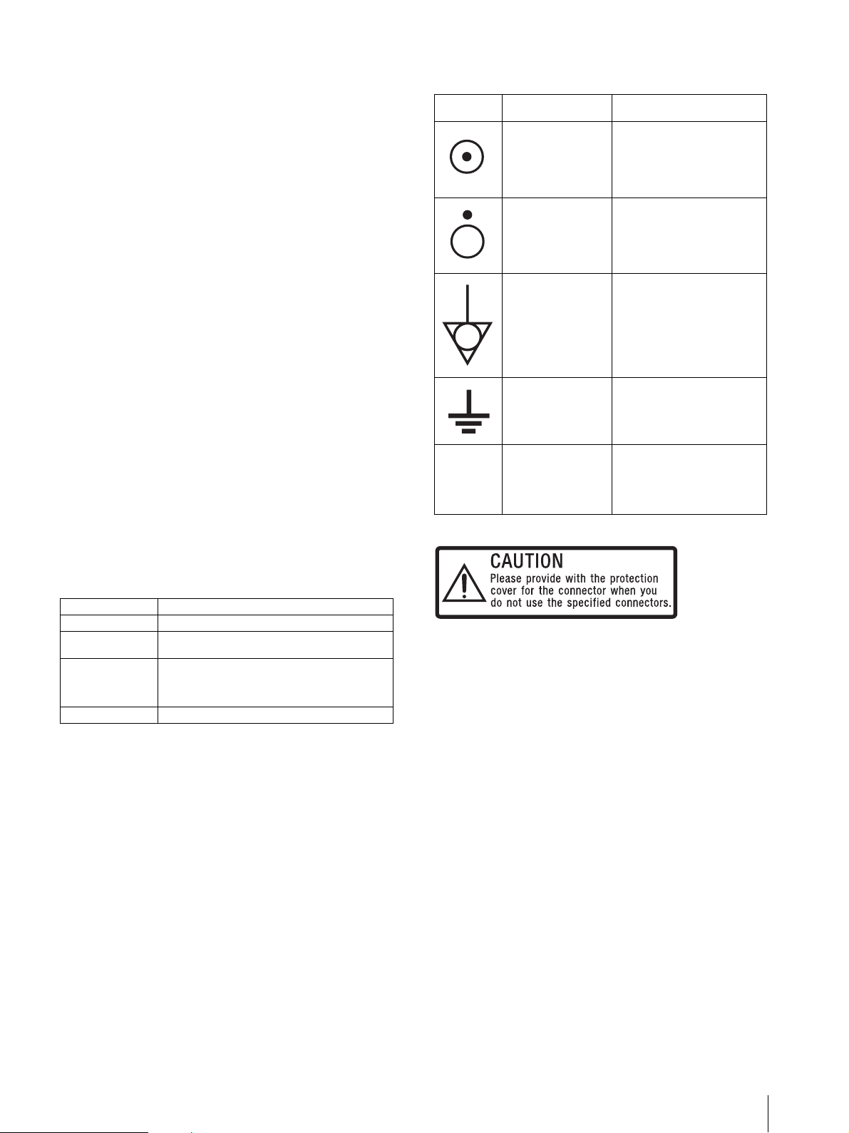
Symbols on the unit
Symbol Location This symbol indicates
Bottom Power switch.
Press to turn the monitor
on.
Bottom Power switch.
Press to turn the monitor
off.
WARNING on power connection
Use a proper power cord for your local power supply.
1. Use the approved Power Cord (3-core mains lead) /
Appliance Connector / Plug with earthing-contacts
that conforms to the safety regulations of each
country if applicable.
2. Use the Power Cord (3-core mains lead) / Appliance
Connector / Plug conforming to the proper ratings
(Voltage, Ampere).
If you have questions on the use of the above Power
Cord / Appliance Connector / Plug, please consult a
qualified service personnel.
WARNING on power connection for medical
use
Please use the following power supply cord. With
connectors (plug or female) and cord types other than
those indicated in this table, use the power supply cord
that is approved for use in your area.
United States and Canada
Plug Type HOSPITAL GRADE*
Cord type Min. Type SJT
Minimum Rating
for Plug and
Appliance
Couplers
Safety Approval UL Listed and CSA
*Note: Grounding reliability can only be achieved when the
equipment is connected to an equivalent receptacle marked ‘Hospital
Only’ or ‘Hospital Grade’.
Min. 18 AWG
10A/125V
Side The equipotential
terminal which brings the
various parts of a system
to the same potential.
Side Functional earth terminal
Front Key inhibit
The setting are locked so
-
that they cannot be
changed.
This label is located on the rear panel of the unit.
See page 18 of these instructions for details about how
to attach the connector covers.
3
Page 4
Important EMC notices for use in the medical environments
• The LMD-3250MD needs special precautions
regarding EMC and needs to be installed and put into
service according to the EMC information provided in
this instructions for use.
• The portable and mobile RF communications
equipment such as cellular phones can affect the
LMD-3250MD.
Warning
The use of accessories and cables other than those
specified, with the exception of replacement parts sold
by Sony Corporation, may result in increased emissions
or decreased immunity of the LMD-3250MD.
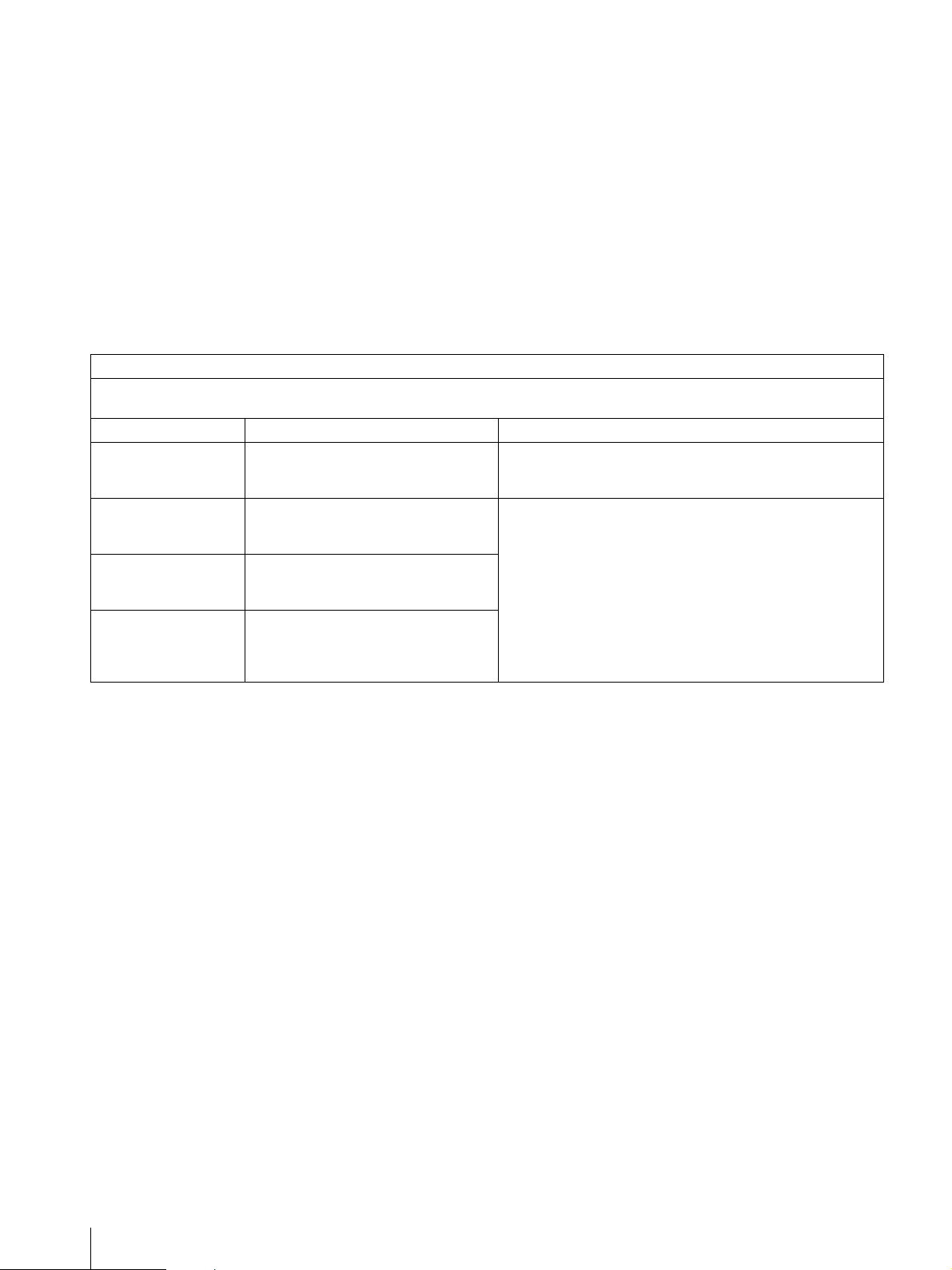
Guidance and manufacturer’s declaration-electromagnetic emissions
The LMD-3250MD is intended for use in the electromagnetic environment specified below.
The customer or the user of the LMD-3250MD should assure that it is used in such an environment.
Emission test Compliance Electromagnetic environment-guidance
RF emissions
CISPR 11
RF emissions
CISPR 11
Harmonic emissions
IEC 61000-3-2
Voltage fluctuations/
flicker emissions
IEC 61000-3-3
Group 1
Class B
Class D
Complies
The LMD-3250MD uses RF energy only for its internal
function. Therefore, its RF emissions are very low and are not
likely to cause any interference in nearby electronic equipment.
The LMD-3250MD is suitable for use in all establishments,
including domestic establishments and those directly connected
to the public low-voltage power supply network that supplies
buildings used for domestic purposes.
Warning
If the LMD-3250MD should be used adjacent to or
stacked with other equipment, it should be observed to
verify normal operation in the configuration in which
it will be used.
4
Page 5
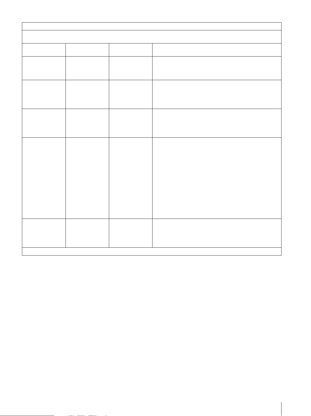
Guidance and manufacturer’s declaration - electromagnetic immunity
The LMD-3250MD is intended for use in the electromagnetic environment specified below. The customer or the user of the LMD3250MD should assure that it is used in such as environment.
Immunity test
Electrostatic
discharge (ESD)
IEC 60601 test
level
±6 kV contact
±8 kV air
Compliance level Electromagnetic environment - guidance
±6 kV contact
Floors should be wood, concrete or ceramic tile. If floors are
covered with synthetic material, the relative humidity should be
±8 kV air
at least 30%.
IEC 61000-4-2
Electrical fast
transient/burst
±2 kV for power
supply lines
±2 kV for power
supply lines
Mains power quality should be that of a typical commercial or
hospital environment.
IEC 61000-4-4
Surge
IEC 61000-4-5
Voltage dips, short
interruptions and
voltage variations
on power supply
input lines
IEC 61000-4-11
Power frequency
(50/60Hz)
magnetic field
IEC 61000-4-8
NOTE: U
is the a.c. mains voltage prior to application of the test level.
T
±1 kV for input/
output lines
±1 kV differential
mode
±2 kV common
mode
< 5% U
(> 95% dip in U
T
for 0.5 cycle
±1 kV for input/
output lines
±1 kV differential
mode
±2 kV common
mode
< 5% UT
)
(> 95% dip in U
T
for 0.5 cycle
Mains power quality should be that of a typical commercial or
hospital environment.
Mains power quality should be that of a typical commercial or
)
hospital environment. If the user of the LMD-3250MD requires
T
continued operation during power mains interruptions, it is
recommended that the LMD-3250MD be powered from an
40% U
T
(60% dip in UT)
for 5 cycles
70% U
T
(30% dip in U
for 25 cycles
< 5% U
(> 95% dip in U
T
T
for 5 sec
)
)
T
40% U
T
(60% dip in UT)
for 5 cycles
70% U
T
(30% dip in U
for 25 cycles
< 5% U
(> 95% dip in U
T
T
for 5 sec
uninterruptible power supply or a battery.
)
)
T
3 A/m 3 A/m Power frequency magnetic fields should be at least characteristic
of a typical location in a typical commercial or hospital
environment.
5
Page 6
Guidance and manufacturer’s declaration - electromagnetic immunity
The LMD-3250MD is intended for use in the electromagnetic environment specified below. The customer or the user of the LMD3250MD should assure that it is used in such as environment.
Immunity test
IEC 60601 test
level
Compliance level Electromagnetic environment - guidance
Portable and mobile RF communications equipment should be
used no closer to any part of the LMD-3250MD, including
cables, than the recommended separation distance calculated
from the equation appliance to the frequency of the transmitter.
Recommended separation distance
Conducted RF
IEC 61000-4-6
Radiated RF
IEC 61000-4-3
NOTE 1: At 80 MHz and 800 MHz, the higher frequency range applies.
NOTE 2: These guidelines may not apply in all situations. Electromagnetic propagation is affected by absorption and reflection from
structures, objects and people.
a Field strengths from fixed transmitters, such as base stations for radio (cellular/cordless) telephones and land mobile radios, amateur
radio, AM and FM radio broadcast and TV broadcast cannot be predicted theoretically with accuracy. To assess the electromagnetic
environment due to fixed RF transmitters, an electromagnetic site survey should be considered. If the measured field strength in the
location in which the LMD-3250MD is used exceeds the applicable RF compliance level above, the LMD-3250MD should be
observed to verify normal operation. If abnormal performance is observed, additional measures may be necessary, such as
reorienting or relocating the LMD-3250MD.
3 Vrms
150 kHz to 80 MHz
3 V/m
80 MHz to 2.5 GHz
3 Vrms
3 V/m
d = 1.2 √P
d = 1.2 √P 80 MHz to 800 MHz
d = 2.3 √P 800 MHz to 2.5 GHz
Where P is the maximum output power rating of the transmitter
in watts (W) according to the transmitter manufacturer and d is
the recommended separation distance in meters (m).
Field strengths from fixed RF transmitters, as determined by an
electromagnetic site survey,
level in each frequency range.
Interference may occur in the vicinity of equipment marked with
following symbol:
a
should be less than the compliance
b
b Over the frequency range 150 kHz to 80 MHz, field strengths should be less than 3 V/m.
6
Page 7
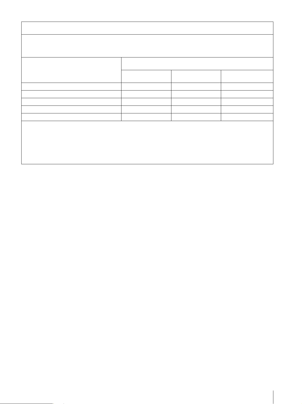
Recommended separation distances between portable and mobile RF communications equipment and the LMD3250MD
The LMD-3250MD is intended for use in an electromagnetic environment in which radiated RF disturbances are controlled. The
customer or the user of the LMD-3250MD can help prevent electromagnetic interference by maintaining a minimum distance between
portable and mobile RF communications equipment (Transmitters) and the LMD-3250MD as recommended below, according to the
maximum output power of the communications equipment.
Rated maximum output power of transmitter
W
150 kHz to 80 MHz
0.01 0.12 0.12 0.23
0.1 0.38 0.38 0.73
1 1.2 1.2 2.3
10 3.8 3.8 7.3
100 12 12 23
For transmitters rated a maximum output power not listed above, the recommended separation distance d in meters (m) can be
estimated using the equation applicable to the frequency of the transmitter, where P is the maximum output power rating of the
transmitter in watts (W) according to the transmitter manufacturer.
NOTE 1: At 80 MHz and 800 MHz, the separation distance for the higher frequency range applies.
Separation distance according to frequency of transmitter
80 MHz to 800 MHz
d = 1.2 √P
m
800 MHz to 2.5 GHz
d = 1.2 √P
d = 2.3 √P
NOTE 2: These guidelines may not apply in all situations. Electromagnetic propagation is affected by absorption and reflection from
structures, objects and people.
7
Page 8

Table of Contents
Precaution .............................................................. 9
On Safety ............................................................ 9
On Installation .................................................... 9
About the LCD Display Panel ............................ 9
About the Fluorescent Tube ............................... 9
On Cleaning ....................................................... 9
Disposal of the Unit ......................................... 10
Recommendation to Use more than One Unit . 10
On Repacking ................................................... 10
On Fan Error .................................................... 10
On Moisture Condensation .............................. 10
Features ................................................................ 10
Location and Function of Parts and Controls .. 12
Front Panel ....................................................... 12
Input signals and adjustable/setting items ........ 14
Side/Rear Panel ................................................ 15
Connecting the AC Power Cord ......................... 17
Installing the Input Adaptor .............................. 18
Removing the Connector Cover ......................... 18
Selecting the Default Settings ............................. 19
Selecting the Menu Language ............................ 20
Using the Menu .................................................... 21
Loading USER MEMORY ................................. 23
Adjustment Using the Menus ............................. 23
Items ................................................................. 23
Adjusting and Changing the Settings ............... 24
STATUS menu............................................. 24
COLOR TEMP/SPACE menu..................... 25
USER CONTROL menu.............................. 25
USER CONFIG menu.................................. 27
REMOTE menu ........................................... 30
KEY INHIBIT menu.................................... 31
USER MEMORY menu .............................. 31
Saving the user memory............................... 31
Troubleshooting ................................................... 32
Specifications ....................................................... 33
Dimensions ........................................................... 39
8
Table of Contents
Page 9

Precaution
On Safety
• Operate the unit on 100-240 V AC only.
• The nameplate indicating operating voltage, etc. is
located on the AC adaptor.
• Should any solid object or liquid fall into the cabinet,
unplug the unit and have it checked by qualified
personnel before operating it any further.
• Unplug the unit from the wall outlet if it is not to be
used for several days or more.
• To disconnect the AC power cord, pull it out by
grasping the plug. Never pull the cord itself.
• The socket-outlet shall be installed near the equipment
and shall be easily accessible.
the monitor becomes warm, the screen returns to
normal.
• If a fixed picture such as a frame of a divided picture
or time code, or a still picture is displayed for a long
time, an image may remain on the screen and be
superimposed as a ghosting image.
• The screen and the cabinet become warm during
operation. This is not a malfunction.
About the Fluorescent Tube
A specially designed fluorescent tube is installed as the
lighting apparatus for this unit. If the LCD screen
becomes dark, unstable or does not turn on, consult your
Sony dealer.
On Cleaning
On Installation
• Prevent internal heat build-up allowing adequate air
circulation.
Do not place the unit on surfaces (rugs, blankets, etc.)
or near materials (curtains, draperies) that may block
the ventilation holes.
• Do not install the unit near heat sources such as
radiators or air ducts, or in a place subject to direct
sunlight, excessive dust, mechanical vibration or
shock.
• Do not place the monitor near equipment which
generates magnetism, such as a transformer or high
voltage power lines.
About the LCD Display Panel
• The LCD panel fitted to this unit is manufactured with
high precision technology, giving a functioning pixel
ratio of at least 99.99%. Thus a very small proportion
of pixels may be “stuck”, either always off (black),
always on (red, green, or blue), or flashing. In
addition, over a long period of use, because of the
physical characteristics of the liquid crystal display,
such “stuck” pixels may appear spontaneously. These
problems are not a malfunction.
• Do not leave the LCD screen facing the sun as it can
damage the LCD screen. Take care when you place the
unit by a window.
• Do not push or scratch the LCD monitor’s screen. Do
not place a heavy object on the LCD monitor’s screen.
This may cause the screen to lose uniformity.
• If the unit is used in a cold place, a residual image may
appear on the screen. This is not a malfunction. When
Before cleaning
Be sure to disconnect the AC power cord from the AC
outlet.
On cleaning the monitor
A material that withstands disinfection is used for the
front protection plate of the medical use LCD monitor.
The protection plate surface is especially treated to
reduce reflection of light. When solvents such as
benzene or thinner, or acid, alkaline or abrasive
detergent, or chemical cleaning cloth are used for the
protection plate surface/monitor surface, the
performance of the monitor may be impaired or the
finish of the surface may be damaged. Take care with
respect to the following:
• Clean the protection plate surface/monitor surface
with a 50 to 70 v/v% concentration of isopropyl
alcohol or a 76.9 to 81.4 v/v% concentration of
ethanol using a swab method. Wipe the protection
plate surface gently (wipe using less than 1 N force).
• Stubborn stains may be removed with a soft cloth such
as a cleaning cloth lightly dampened with mild
detergent solution using a swab method and then clean
using the above chemical solution.
Never use solvents such as benzene or thinner, or acid,
alkaline or abrasive detergent, or chemical cleaning
cloth for cleaning or disinfection, as they will damage
the protection plate surface/monitor surface.
• Do not use unnecessary force to rub the protection
plate surface/monitor surface with a stained cloth.
The protection plate surface/monitor surface may be
scratched.
• Do not keep the protection plate surface/monitor
surface in contact with a rubber or vinyl resin product
for a long period of time. The finish of the surface
may deteriorate or the coating may come off.
Precaution
9
Page 10

Disposal of the Unit
• Do not dispose of the unit with general waste.
Do not include the monitor with household waste.
• The fluorescent tube includes mercury. Dispose of the
monitor in accordance with the regulations of your
local sanitation authority.
Recommendation to Use more than One Unit
As problems can occasionally occur for the monitor,
when the monitor is used for safety control of personnel,
assets or stable picture, or for emergencies, we strongly
recommend you use more than one unit or prepare a
spare unit.
On Repacking
Do not throw away the carton and packing materials.
They make an ideal container which to transport the
unit.
If you have any questions about this unit, contact your
authorized Sony dealer.
On Fan Error
Features
Compliance with medical safety
standards in America, Canada and
Europe
UL60601-1 for America, CSA C22.2 No.601.1 for
Canada and EN 60601-1 for Europe have been obtained
for this monitor.
The monitor is designed for use in the medical treatment
field, with the sheet switch, screen protect panel, etc.
Picture
Fully digital 10-bit signal processing circuit
As well as digital signals, all signals including analog
signals are converted into digital signals. All signals are
processed using a fully digital 10-bit processing circuit
so that an image is produced in smooth gradation
without any deterioration of quality.
Two color system available
The monitor can display NTSC and PAL signals by
connecting this unit.
Auto chroma/phase function
The chroma and phase of the decoder are automatically
adjusted with the auto chroma phase function.
The fan for cooling the unit is built in. When the fan
stops and the RETURN button on the front panel blinks
for fan error indication, turn off the power and contact an
authorized Sony dealer.
On Moisture Condensation
If the unit is brought directly from a cold place to a warm
place, or the unit is warm and the ambient temperature
cools suddenly (by air-conditioning, for example),
moisture may condense on the surface or inside of the
unit, or create a mist residue inside the protection plate.
This is called moisture condensation, and is not a
malfunction of the product itself, although it may cause
damage to the unit.
Leave the unit in a condensation free area.
If moisture condensation has occurred, turn off the unit
and do not use it until moisture condensation has
evaporated.
High image-quality/high-resolution Full HD
LCD panel with 10-bit driver
A Full HD high-resolution/high-gradient (1920 × 1080
dots) panel and high brightness/ultra-wide field of view
technology enables you to use the monitor under various
lighting conditions and in numerous ways (installing on
wall, using several monitors to view an image, and so
on.).
Because a color filter with wide-color reproduction and
LCD materials with high response speed are used, the
motion picture of the video signal is displayed clearer.
This monitor also performs sampling of signals at high
frequencies and provides a high resolution of 700 TV
scanning lines or more during the RGB or component
signal (480/60I, 575/50I) input.
Input
Accepts analog RGB input signals
Adopting the scan converter allows this monitor to
detect VGA, SVGA, XGA and SXGA analog RGB
signals input to the HD15 input connector.
*1
10
Features
Page 11

Accepts DVI-D (digital) input signals
*1
Adopting the scan converter allows this monitor to
detect VGA, SVGA, XGA and SXGA digital computer
signals input to the DVI input connector.
To view SXGA signals when the DVI input is selected,
use the cable within 3 m (118
*1
For acceptable formats, see “About the preset signal” on
page 35.
1
/8 inches) in length.
Aspect setting
You can set the monitor to 4:3 or 16:9 display mode
according to the input signal.
Scan function
You can select the display from among “NORMAL”,
“OVER” and “NATIVE” (720P only) except the HD15
and DVI input signals.
Optional slot for the video signal
One optional input adaptor can be attached. The
composite, Y/C, component, analog RGB or SDI signal
can be input depending on the input connectors of the
board to be used.
Multi-format
*2
NTSC or PAL color system or DTV format, such as
720P, 1080i, etc. can be selected automatically.
*2
For acceptable formats, see “Available signal formats” on
page 34.
External sync input
The unit can be operated on the sync signal supplied
from an external sync generator.
Functions
APA (Auto Pixel Alignment) function
You can display pictures from the HD15 input connector
in the appropriate picture by simply pressing the APA
key.
Automatic termination (connector with
mark only)
The input connector is terminated internally at 75 ohms
when nothing has been connected to the output
connector. If a cable is connected to the output
connector, the internal terminal is automatically
released and the signals input to the input connector are
output to the output connector (loop-through).
Select color temperature and gamma mode
You can select the color temperature from among three
(HIGH, LOW, LOW2) settings and gamma mode from
between two settings (2.2, DICOM). You can also adjust
the color temperature to the appropriate setting in
“USER”.
Select language display
You can select your language for the display from seven
languages - English, French, German, Spanish, Italian,
Japanese and Chinese.
Power saving function
The monitor enters into power saving mode to reduce
the power consumption when no signal is input.
Key inhibit function
You can inhibit the key to prevent missing an operation.
User memory function
You can save the 20 picture settings with the name. The
user memory data can be saved or loaded between the
monitor and the equipment (PC, etc.) connected in
serial remote mode.
Two kinds of ground terminals
Two kinds of ground terminals are built into the monitor
to equal the electric potential.
External remote function
The input signal is selected or various items are adjusted
by use of the serial (Ethernet) remote function. You can
connect this unit to the monitor by the Ethernet
(10BASE-T/100BASE-TX) connection and controlled
remotely on the network.
For more information, see SERIAL REMOTE of
REMOTE menu on page 30.
Other
Optional stand
It is more convenient to install the monitor on a desk by
using the optional stand (SU-32FW).
Two-dis play
Two kinds of input signals are put on the monitor.
For more information, see MULTI DISPLAY of “MULTI
DISPLAY SETTING” on page 28.
Color space feature
You can select ITU-R BT.709 for the color space
settings.
Features
11
Page 12

Location and Function of Parts and Controls
Front Panel
1
0
qa
qs
COMPOSITE
Y/C
RGB
COMPONENT
A-1
A-2
B-1
B-2
HD15
DVI
F1
F2
F3
F4
USER MEM
CONTROL
+
CONTRAST
–
+
PHASE
–
+
CHROMA
–
+
BRIGHT
–
MENU
+
–
ENTER
RETURN
2
3
4
5
6
7
8
9
a Tally lamp
You can check the status of the monitor by the color of
the tally lamp.
The tally lamp lights in green according to the setting of
PARALLEL REMOTE in the REMOTE menu.
b Power indicator
When the power is turned on, the power indicator light
in green.
c - (key inhibit) indicator
Lights in white when KEY INHIBIT in the KEY
INHIBIT menu is set to ON.
d CONTROL button
Press to display the buttons on the front panel. Press
again to clear the display.
e CONTRAST buttons
Adjusts the picture contrast.
Press the + button to make the contrast higher or the –
button to make it lower.
f PHASE buttons
Adjusts color tones.
Press the + button to make the skin tones greenish or the
– button to make them purplish.
g CHROMA buttons
Adjusts the color intensity.
Press the + button to increase the color intensity or the –
button to decrease it.
h BRIGHT (brightness) buttons
Adjusts the picture brightness.
Press the + button to increase the brightness or the –
button to decrease it.
i Menu operation buttons
Displays or sets the on-screen menu.
MENU button
Press to display the on-screen menu.
Press again to clear the menu.
+/– buttons
Press to select the items and setting values.
ENTER button
Press to confirm a selected item on the menu.
When the menu is not displayed and the button is
pressed, the distinguished signal format is displayed.
RETURN button
When the menu is displayed and the button is pressed,
the value of an item is reset to the previous value.
When the menu is not displayed and the button is
pressed, the function selected in FUNCTION
BUTTON SETTING of the USER CONFIG menu is
displayed on the side of the F1 to F4 button. Also,
when the fan stops, this button blinks.
12
Location and Function of Parts and Controls
Page 13

j Input select buttons
Press the button to monitor the signal input to each
connector.
A-1, A-2, B-1 and B-2 buttons are used when an
optional input adaptor has been installed in the option
slot.
COMPOSITE button: to monitor the signal through
the COMPOSITE IN connector
Y/C button: to monitor the signal through the Y/C IN
connector
RGB button: to monitor the RGB signal through the
connectors for the R/G/B signal input
COMPONENT button: to monitor the component
signal through the connectors for Y/P
B/PR signal input
A-1 button: to monitor the signal from connector 1
(the connectors for the R/G/B signal input in BKM229X) of the input adaptor installed to the option slot
A
A-2 button: to monitor the signal from connector 2
(the connectors for Y/P
B/PR signal input in BKM-
229X) of the input adaptor installed to the option slot
A
B-1 button: to monitor the signal from connector 1
(the connectors for the R/G/B signal input in BKM229X) of the input adaptor installed to the option slot
B
B-2 button: to monitor the signal from connector 2
(the connectors for Y/P
B/PR signal input in BKM-
229X) of the input adaptor installed to the option slot
B
HD15 button: to monitor the signal through the
HD15 input connector
DVI button: to monitor the signal through the DVI-D
input connector
k Function buttons
You can turn the assigned function on or off.
The factory setting is as follows;
F1 button: EXT SYNC
F2 button: SCAN
F3 button: ASPECT
F4 button: MULTI DISPLAY
You can assign the function from among SCAN,
ASPECT, EXT SYNC, BLUE ONLY, MONO, MULTI
DISPLAY, APA and MIRROR IMAGE in FUNCTION
BUTTON SETTING of the USER CONFIG menu (see
page 29).
For details of the function assigned to the function
button, see page 29.
l USER MEM (user memory) button
Press to load the picture settings saved in the USER
MEMORY menu (on page 31).
Location and Function of Parts and Controls
13
Page 14

Input signals and adjustable/setting items
Item Video*
CONTRAST*
BRIGHT*
CHROMA*
PHASE*
1
1
1
1
3
,
B & W*3Component*
3
Y/C*
SD HD SD HD D1*
a a a aaaaa a a
a a a aaaaa a a
a × a aaaaa a a
a
× a aaaaa a a
(NTSC)
APERTURE
COLOR TEMP
COLOR SPACE
AUTO CHROMA/
PHASE
ACC
CTI
V SHARPNESS
MATRIX*
COMPONENT LEVEL
2
a a a aaaaa a a
a a a aaaaa a a
a a a aaaaa a a
a
a
×
× Ч ЧЧЧЧЧ Ч ×
aa
a × a ЧЧЧЧЧ Ч ×
aaa× a × a ×× ×
××a
××
a
(480/60I)
NTSC SETUP
SCAN
GAMMA
ASPECT*
BLUE ONLY
MONO
APA
SIZE
SHIFT
PITCH
DOT PHASE
POWER SAVING
PICTURE DELAY
MIN*
MULTI DISPLAY
10
7
a
(NTSC)
a a a aaaaa ×*
a a a aaaaa a a
aaa× a × a ××*
a × a aaaaa ××
a × aa××aa ××
× × Ч ЧЧЧЧЧ Ч a*
× × Ч ЧЧЧЧЧ Ч a
a a a aaaaa × a
× × Ч ЧЧЧЧЧ Ч a
× × Ч ЧЧЧЧЧ Ч a
a a a aaaaa a a
a a a aaaaa ×*
a a a aaaaa a*
a
(480/60I)
Ч ЧЧЧЧЧ Ч ×
a : Adjustable/can be set
× : Not adjustable/cannot be set
*1 Adjustment of SUB CONTROL is the same.
*2 When a component signal (480/60I or 480/60P) is input
and the COMPONENT LEVEL is set to SMPTE, this can
be switchable.
*3 When a BKM-227W is installed, the number of the input
connector is increased.
*4 When a BKM-229X is installed, the number of the input
connector is increased.
*5 When a BKM-220D or BKM-243HS is installed, the
signal can be input.
4
×
×××
*6 When a BKM-243HS is installed, the signal can be input.
*7 Only the interlace signal is input.
*8 The signal can operate with PRESET 2 to 6. (See page 37.)
*9 The signal can only be selected in the main display. (See
*10 The signal cannot operate with PRESET 7 and 8.
*11 The signal can only operate with PRESET 1.
*12 The signal can only operate with PRESET 6.
Input signal
4
RGB*
××
SDI Computer
5
HD*
6
DVI HD15
×× × ×
×××× × ×
×
“SUB INPUT SELECT” on page 28.)
×× ×
8
12
8
9
×*
×*
×*
a*
8
12
11
8
9
14
Location and Function of Parts and Controls
Page 15

Side/Rear Panel
qs
qd
qf
qg
qh
qa
5
6
7
8
9
IN
COMPOSITE
IN
IN G/Y OUT
IN B/P
IN R/P
EXT
IN
SYNC
Y/C
OUT
OUT
B OUT
R OUT
OUT
0
a DC 5V/24V IN connector
Connect the DC connector of the supplied AC adaptor.
b / (power) switch
The power is turned on or off.
The monitor is turned on by pressing side .
c Loop-through output connectors
Outputs the signals input to the input connectors (5 to
0). Connect to the analog input (composite, Y/C,
analog component, analog RGB or external sync) of
equipment, according to the input signal.
When a cable is connected to one of these connectors,
the 75-ohm termination of the corresponding input is
automatically released, and the signal input to the input
connector is output.
+24V
DC
5V24V IN
+5V
2
1
3
4
f B/P
Input connector for B of RGB signals and P
B IN connector (BNC)
B (blue color
difference) of component signals.
g R/P
Input connector for R of RGB signals and P
R IN connector (BNC)
R (red color
difference) of component signals.
h EXT SYNC IN (external sync input) connector
(BNC)
When this unit operates on an external sync signal,
connect the reference signal from a sync generator to
this connector.
To use the external sync signal, press the function button
that EXT SYNC is assigned (F1 button at the factory
setting).
d /I (Equipotential/Function Earth) terminal
(equipotential) terminal
Connects the equipotential plug.
I (function earth) terminal
Connects the earth cable.
e G/Y IN connector (BNC)
Input connector for G of RGB signals and component Y
(luminance) signals.
Note
When inputting a video signal with the jitters, etc. the
picture may be disturbed. We recommend using the
TBC (time base corrector).
i Y/C IN connector (4-pin mini-DIN)
Input connector for Y/C signals.
j COMPOSITE IN connector (BNC)
Input connector for composite signals.
Location and Function of Parts and Controls
15
Page 16

k Optional input slot
An optional input adaptor can be installed according to
your system configuration (see page 18).
The upper slot is A and the lower slot is B.
Press the A-1, A-2, B-1 or B-2 button to select the
signal.
The BKM-243HS (HD/D1-SDI input adaptor) is
preattached in slot A in this unit.
l PARALLEL REMOTE connector (modular
connector, 8-pin)
Forms a parallel switch and controls the monitor
externally.
When the unit is shipped from the factory, a connector
cover is attached to this connector. Remove it before
using the connector.
For removing the connector cover, see page 18.
For details on the pin assignment and factory setting
function assigned to each pin, see page 34.
CAUTION
For safety, do not connect the connector for peripheral
device wiring that might have excessive voltage to this
port. Follow the instructions for this port.
For details, refer to the Interface Manual for
Programmers (saved in the supplied CD-ROM,
Japanese and English only.)
o DVI-D input connector (DVI-D)
Inputs DVI Rev.1.0 applicable digital RGB signal.
To view the signals of the SXGA and higher resolution
when the DVI input is selected, use the cable within 3 m
1
(118
/8 inches) in length.
p HD15 input connector (D-sub 15-pin, female)
Inputs an analog RGB video signal (0.7 Vp-p, positive
polarity) and sync signal.
The Plug & Play function corresponds to DDC2B.
m SERIAL REMOTE connector (RJ-45)
Connect to the network by using a 10BASE-T/
100BASE-TX LAN cable (shielded type, optional).
When the unit is shipped from the factory, a connector
cover is attached to this connector. Remove it before
using the connector.
For removing the connector cover, see page 18.
For details on this connector, refer to the Interface
Manual for Programmers (saved in the supplied CDROM, Japanese and English only.)
CAUTION
• When an optional LAN cable is connected, use a
shield type cable to prevent miss-operation due to
noises.
• For safety, do not connect the connector for peripheral
device wiring that might have excessive voltage to this
port. Follow the instructions for this port.
• The connection speed may be affected by the network
system. This unit does not guarantee the
communication speed or quality of 10BASE-T/
100BASE-TX.
n SERIAL REMOTE RS-232C connector (D-sub
9-pin, female)
Connect to the RS-232C control connector on external
equipment connected to the monitor. The monitor can
be operated according to control commands sent from
external equipment connected to it.
For details on the pin assignment and factory setting
function assigned to each pin, see page 34.
16
Location and Function of Parts and Controls
Page 17

Connecting the AC Power Cord
Connect the supplied AC power cord as illustrated.
Two kinds of AC plug holders are supplied with this
unit. Use the AC plug holder that fits the AC power cord
most securely.
1
Plug the AC power cord into the AC IN socket on
the AC adaptor. Then, attach the AC plug holder to
the AC power cord.
AC IN socket
3
Insert the DC IN connector into the DC 5V/24V IN
connector on the bottom of this unit until it locks.
AC power cord
AC plug holder (Supplied)
2
Slide the AC plug holder over the cord until it locks.
To remove the AC power cord
First, pull out the AC plug holder while pressing the lock
levers.
Next, pull out the DC IN connector from the DC 5V/24V
IN connector while pressing the lock lever.
Connecting the AC Power Cord
17
Page 18

Installing the Input
Removing the
Adaptor
Before installing the input adaptor, disconnect the power
cord.
1
Remove the panel of the optional input slot.
2
Insert the input adaptor into the slot.
Connector Cover
When the unit is shipped from the factory, a connector
cover is attached to the PARALLEL REMOTE
connector and the SERIAL REMOTE connector (RJ-
45).
To use the connector, remove the connector cover as
follows.
Before removing the connector cover, disconnect the
power cord.
Connector cover
1
Remove the screw of the connector cover.
3
Tighten the screws.
2
Remove the connector cover.
Save the screw and cover, so that you can reattach the
cover if necessary.
Caution
This connector is designed to allow direct contact with
conductive circuits. Weak voltage may be present
because of a failure in this unit. To prevent patients from
touching this connector accidentally, attach the
connector cover when the connector is not being used to
connect to other devices.
18
Installing the Input Adaptor / Removing the Connector Cover
Page 19

Selecting the Default Settings
When you turn on the unit for the first time after
purchasing it, select the area where you intend to use this
unit from among the options.
The default setting values for each area
3
1
5
4
3
1NORTH
AMERICA
2LATIN AMERICA
PAL&PAL-N
AREA
NTSC&PAL-M
AREA
3AFRICA AUSTRALASIA
EUROPE MIDDLE-EAST
4ASIA EXCEPT
JAPAN
3
COLOR
TEMP
LOW BETA7.5 7.5
ARGENTINA LOW SMPTE 0
PARAGUAY LOW SMPTE 0
URUGUAY LOW SMPTE 0
OTHER AREA LOW BETA7.5 7.5
LOW SMPTE 0
NTSC AREA LOW BETA7.5 7.5
PAL AREA LOW SMPTE 0
5JAPAN HIGH SMPTE 0
2
COMPONENT
LEVEL
NTSC
SETUP
+
–
+
–
+
–
MENU
+
–
+
+
–
–
2~3
ENTER
1
1
Turn on the unit with the / (power) switch on
the bottom panel.
The SELECT SETTING screen appears.
1North America
S E L E C T S E T T I N G
N O R T H A M E R I C A
L A T I N A M E R I C A
A F R I C A A U S T R A L A S I A E
A S I A E X C E P T J A P A N
J A P A N
2
Press the + or – button to select the area where you
intend to use the unit and press the ENTER button.
If you select either 1, 3 or 5
The confirmation screen is displayed. Confirm the
selected area. When the setting is wrong, press the
RETURN button to return to the previous screen.
2Latin America
3Africa Australia/New
Zealand, Europe,
Middle East, Russia
4Asia Except Japan
5Japan
S E L E C T T H I S A R E A ?
N O R T H A M E R I C A
[ E N T E R ] Y E S
[ R E T U R N ] NO
If you select either 2 or 4
One of the following screens appears. Press the
+
or – button to narrow the area further and then press
the ENTER button.
The confirmation screen is displayed. Confirm the
selected area. When the setting is wrong, press the
RETURN button to return to the previous screen.
Selecting the Default Settings
19
Page 20

2 If LATIN AMERICA is selected:
PAL&PAL-N area
L A T I N A M E R I C A
P A L & P A L - N _ A R E A
A R G E N T I N A
P A R A G U A Y
U R U G U A Y
N T S C & P A L - M A R E A
O T H E R A R E A
Argentina
Paraguay
Uruguay
NTSC&PAL-M area
Other area
4 If ASIA EXCEPT JAPAN is selected:
Customers who will use this unit in the shaded
areas shown in the map below should select NTSC
AREA.
Other customers should select PAL AREA.
Selecting the Menu Language
You can select one of seven languages (English, French,
German, Spanish, Italian, Japanese, Chinese) for
displaying the menu and other on-screen displays.
“ENGLISH (English)” is selected in the default setting.
The current settings are displayed in place of the x
marks on the illustrations of the menu screen.
2
+
–
+
–
+
–
MENU
+
–
+
–
ENTER
+
–
3
4~6
A S I A E X C E P T J A P A N
N T S C _ A R E A
P A L A R E A
3
Press the ENTER button.
NTSC area
PAL area
The SELECT SETTING screen disappears and the
menu item settings suitable for the selected area are
applied.
Note
When you have selected the wrong area, set the
following items using the menu.
• COLOR TEMP (on page 25)
• COMPONENT LEVEL (on page 27)
• NTSC SETUP (on page 27)
See “The default setting values for each area” (page 19)
on the setting value.
1
1
Turn on th e unit.
2
Press the CONTROL button.
The operation buttons are displayed.
3
Press the MENU button.
The menu appears.
The menu presently selected is shown in yellow.
STATUS 1 /2
FORMAT xxxxxxxxx
xxxxxxxx
COLOR TEMP xxx
COMPONENT LEVEL xxxxx
NTSC SETUP xxxxxxxxx
SCAN MODE xxxxxxxx
POWER SAVING xx
4
Press the + or – button to select SYSTEM
SETTING of the USER CONFIG (User
Configuration) menu, then press the ENTER
button.
20
Selecting the Menu Language
Page 21

The setting items (icons) in the selected menu are
displayed in yellow.
USER CONFIG – SYSTEM SETTING
MATRIX: xxx
COMPONENT LEVEL: xxxx
NTSC SETUP: x
GAMMA: xxx
FORMAT DISPLAY: xxxx
LANGUAGE: ENGLISH
POWER SAVING: xxx
PICTURE DELAY MIN: xxx
5
Press the + or – button to select “LANGUAGE,”
then press the ENTER button.
The selected item is displayed in yellow.
USER CONFIG – SYSTEM SETTING
MATRIX: xxx
COMPONENT LEVEL: xxxx
NTSC SETUP: x
GAMMA: xxx
FORMAT DISPLAY: xxxx
LANGUAGE: ENGLISH
POWER SAVING: xxx
PICTURE DELAY MIN: xxx
Using the Menu
The unit is equipped with an on-screen menu for making
various adjustments and settings such as picture control,
input setting, set setting change, etc. You can also
change the menu language displayed in the on-screen
menu.
To change the menu language, see “Selecting the Menu
Language” on page 20.
The current settings are displayed in place of the x
marks on the illustrations of the menu screen.
1
+
–
+
–
+
–
MENU
+
–
+
–
ENTER
+
–
2
3~5
6
Press the + or – button to select a language, then
press the ENTER button.
The menu changes to the selected language.
USER CONFIG – SYSTEM SETTING
MATRIX: xxx
COMPONENT LEVEL: xxxxx
NTSC SETUP: x
GAMMA: xxx
FORMAT DISPLAY: xx
LANGUAGE: ENGLISH
POWER SAVING: xx
PICTURE DELAY MIN: x
To clear the menu
Press the MENU button.
The menu disappears automatically if a button is not
pressed for one minute.
RETURN button
1
Press the CONTROL button.
The operation buttons are displayed.
2
Press the MENU button.
The menu appears.
The menu presently selected is shown as a yellow
button.
STATUS 1/2
FORMAT
COLOR TEMP
COMPONENT LEVEL
NTSC SETUP
SCAN MODE
POWER SAVING
xxxxxxxxx
xxxxxxxx
xxx
xxxxx
xxxxxxxx
xx
x
3
Use the + or – button to select a menu, then press
the ENTER button.
Using the Menu
21
Page 22

The menu icon presently selected is shown in
yellow and setting items are displayed.
USER CONFIG – SYSTEM SETTING
MATRIX: xxx
COMPONENT LEVEL: xxxxx
NTSC SETUP: x
GAMMA: xxx
FORMAT DISPLAY: xx
LANGUAGE: ENGLISH
POWER SAVING: xx
PICTURE DELAY MIN: x
4
Select an item.
About the memory of the settings
The settings are automatically stored in the monitor
memory.
Use the
+ or – button to select the item, then press
the ENTER button.
The item to be changed is displayed in yellow.
If the menu consists of multiple pages, press
button to go to the desired menu page.
5
Make the setting or adjustment on an item.
When changing the adjustment level:
To increase the number, press the
+ button.
To decrease the number, press the – button.
Press the ENTER button to confirm the number,
then restore the original screen.
When changing the setting:
Press the
+ or – button to change the setting.
Press the ENTER button to confirm the setting.
When returning the adjustment or setting to the
previous value:
Press the RETURN button before pressing the
ENTER button.
Notes
• An item displayed in black cannot be accessed.
You can access the item if it is displayed in white.
• If the key inhibit has been turned on, all items are
displayed in black. To change any of the items,
turn the key inhibit to OFF first.
+ or –
For details on the key inhibit, see page 31.
To return the display to the previous
screen
Press the RETURN button.
To clear the menu
Press the MENU button.
The menu disappears automatically if a button is not
pressed for one minute.
22
Using the Menu
Page 23

Loading USER MEMORY
You can load the picture settings saved in the USER
MEMORY menu (on page 31).
COMPOSITE
Y/C
RGB
COMPONENT
A-1
A-2
B-1
B-2
HD15
DVI
F1
F2
F3
F4
USER MEM
USER MEM
1
ENTER
+
–
2~3
+
–
+
–
+
–
+
–
+
–
Adjustment Using the Menus
Items
The screen menu of this monitor consists of the
following items.
STATUS (the items indicate the
current settings.)
For the video input
FORMAT
COLOR TEMP
COMPONENT LEVEL
NTSC SETUP
SCAN MODE
POWER SAVING
Model name and serial number
OPTION A and serial number
OPTION B and serial number
1
Press the USER MEM button.
The USER MEMORY menu appears.
USER MEMORY 1/3
xDEFAULT
· 01 USER01
· 02 USER02
· 03 USER03
· 04 USER04
· 05 USER05
· 06 USER06
2
Select the memory number.
+ or – button: to select the memory number
3
Press the ENTER button.
After loading the picture settings from the selected
memory, the menu disappears.
To stop selecting the memory
Press the USER MEM button.
The USER MEMORY menu disappears.
To reset the settings
Select “DEFAULT”, then press the ENTER button.
For the DVI/HD15 input
FORMAT
fH
fV
COLOR TEMP
POWER SAVING
Model name and serial number
OPTION A and serial number
OPTION B and serial number
COLOR TEMP/SPACE
COLOR TEMP
MANUAL ADJUSTMENT
COLOR SPACE
USER CONTROL
For the video input
AUTO CHROMA/PHASE
SUB CONTROL
PICTURE CONTROL
INPUT SETTING
For the DVI/HD15 input
SUB CONTROL
PICTURE CONTROL
USER CONFIG
SYSTEM SETTING
Loading USER MEMORY / Adjustment Using the Menus
23
Page 24

MATRIX
COMPONENT LEVEL
NTSC SETUP
GAMMA
FORMAT DISPLAY
LANGUAGE
POWER SAVING
PICTURE DELAY MIN
MULTI DISPLAY SETTING
MULTI DISPLAY ENABLE
MULTI DISPLAY
SUB INPUT SELECT
POSITION
FRAME
FUNCTION BUTTON SETTING
F1 BUTTON
F2 BUTTON
F3 BUTTON
F4 BUTTON
COMPUTER DETECT
DVI
HD15
REMOTE
PARALLEL REMOTE
SERIAL REMOTE
KEY INHIBIT
KEY INHIBIT
For the video input
STATUS 1/2
FORMAT xxxxxxxxx
xxxxxxxx
COLOR TEMP xxx
COMPONENT LEVEL xxxxx
NTSC SETUP x
SCAN MODE xxxxxxxx
POWER SAVING xx
STATUS 2/2
LMD-3250MD xxxxxxx
OPTION A
BKM-243HS xxxxxxx
OPTION B
NOT INSTALLED
• Signal format
• Color temperature
• Component level
•NTSC setup
• Scan mode
•Power saving
• Model name and serial number
• OPTION A and serial number
• OPTION B and serial number
For the DVI/HD15 input
USER MEMORY
01 to 20
Adjusting and Changing the Settings
STATUS menu
The STATUS menu is used to display the current status
of the unit. The following items are displayed:
STATUS 1/2
FORMAT xxx
xxxxxxx
fH xxxxxxx
fV xxxxx
COLOR TEMP xxxx
POWER SAVING xx
STATUS 2/2
LMD-3250MD xxxxxxx
OPTION A
BKM-243HS xxxxxxx
OPTION B
NOT INSTALLED
• Signal format
•fH
•fV
• Color temperature
•Power saving
• Model name and serial number
• OPTION A and serial number
• OPTION B and serial number
24
Adjustment Using the Menus
Page 25

COLOR TEMP/SPACE menu
The COLOR TEMP/SPACE menu is used for adjusting
the picture white balance or color space.
You need to use the measurement instrument to adjust
the white balance.
Recommended: Konica Minolta color analyzer CA-210
COLOR TEMP/SPACE
COLOR TEMP: xxxxxx
MANUAL ADJUSTMENT:
ADJUST GAIN:
ADJUST BIAS:
COPY FROM: xxx
COLOR SPACE: x
Submenu Setting
COLOR TEMP Selects the color temperature from
MANUAL
ADJUSTMENT
COLOR SPACE Selects the color space either ITU-
among “HIGH”, “LOW” or
“USER” and “LOW2” setting.
If you set the COLOR TEMP to
USER setting, the item displayed is
changed from black to white, which
means you can adjust the color
temperature.
The set values are memorized.
• ADJUST GAIN: Adjusts the
color balance (GAIN).
• ADJUST BIAS: Adjusts the
color balance (BIAS).
• COPY FROM: If you select
“HIGH”, “LOW” or
“LOW2”, the white balance
data for the selected color
temperature will be copied
in the “USER” setting.
709 or OFF. OFF sets the color
space to the original color
reproduction of the LCD panel.
USER CONTROL menu
The USER CONTROL menu is used for adjusting the
picture.
Items that cannot be adjusted depending on the input
signal are displayed in black.
For details of input signals and adjustable/setting items,
see page 14.
For the video input
USER CONTROL 1/3
AUTO CHROMA/PHASE
AUTO ADJ VALUE: xx
START:
USER CONTROL 2/3
SUB CONTROL
CONTRAST: x
BRIGHTNESS: x
CHROMA: x
PHASE: x
APERTURE: x
BACKLIGHT: x
USER CONTROL 3/3
PICTURE CONTROL
ACC: xx
CTI: x
V SHARPNESS: x
INPUT SETTING
SHIFT H: xxx
SHIFT V: xx
Submenu Setting
AUTO CHROMA/
PHASE
Adjusts color intensity (CHROMA)
and tones (PHASE).
• AUTO ADJ VALUE: Selects
• START: The auto adjustment
ON or OFF of the auto
adjustment. When you set
to OFF, this parameter is
reset to the factory setting.
When you set to ON, the
automatically adjusted value
is enabled.
starts when you display the
color bar signals (Full/
SMPTE/EIA) on the screen
and press the ENTER
button. After adjusting the
color intensity, press the
MENU button to clear the
adjustment screen. After the
adjustment is done correctly,
the AUTO ADJ VALUE is
automatically set to ON.
Adjustment Using the Menus
25
Page 26

* The 1/3
Submenu Setting
SUB CONTROL Adjusts finely the adjustment range
of the button on the front panel for
CONTRAST, BRIGHTNESS,
CHROMA and PHASE.
• CONTRAST: Adjusts the picture
contrast.
• BRIGHTNESS: Adjusts the
picture brightness.
• CHROMA: Adjusts color
intensity. The higher the
setting, the greater the
intensity. The lower the
setting, the lower the
intensity.
• PHASE: Adjusts color tones.
The higher the setting, the
more greenish the picture.
The lower the setting, the
more purplish the picture.
• APERTURE: Adjusts the picture
sharpness.
The higher the setting, the
sharper the picture. The
lower the setting, the softer
the picture.
• BACKLIGHT: Adjusts the
backlight. When the setting
is changed, the brightness of
the backlight is changed.
PICTURE CONTROL Adjusts the picture.
• ACC (Auto Color Control): Sets
ACC circuit on or off.
To check the fine
adjustment, select OFF.
Normally select ON.
• CTI (Chroma Transient
Improvement): When a low
color resolution signal is
input, a crisp image can be
displayed. When the setting
is higher, the picture
becomes even more crisp.
• V SHARPNESS: A crisp image
can be displayed. When the
setting is higher, the picture
becomes even more crisp.
INPUT SETTING • SHIFT H: Adjusts the position of
the picture. As the setting
increases, the picture moves
to the right, and as the
setting decreases, the picture
moves to the left.
• SHIFT V: Adjusts the position of
the picture. As the setting
increases, the picture moves
up, and as the setting
decreases, the picture moves
down.
For the DVI/HD15 input
menu cannot be adjusted.
USER CONTROL 2/3
SUB CONTROL
CONTRAST: x
BRIGHTNESS: x
CHROMA: x
PHASE: x
APERTURE: x
BACKLIGHT: x
USER CONTROL 3/3
PICTURE CONTROL
SIZE H: xx
SIZE V: xx
SHIFT H: xx
SHIFT V: xx
DOT PHASE: xx
PITCH: xx
RESOLUTION: xxx
RESET
Submenu Setting
SUB CONTROL Adjusts finely the adjustment range
of the button on the front panel for
CONTRAST, BRIGHTNESS,
CHROMA and PHASE.
• CONTRAST: Adjusts the picture
contrast.
• BRIGHTNESS: Adjusts the
picture brightness.
• CHROMA: Adjusts color
intensity. The higher the
setting, the greater the
intensity. The lower the
setting, the lower the
intensity.
• PHASE: Adjusts color tones.
The higher the setting, the
more greenish the picture.
The lower the setting, the
more purplish the picture.
• APERTURE: Adjusts the picture
sharpness.
The higher the setting, the
sharper the picture. The
lower the setting, the softer
the picture.
• BACKLIGHT: Adjusts the
backlight. When the setting
is changed, the brightness of
the backlight is changed.
26
Adjustment Using the Menus
Page 27

Submenu Setting
PICTURE CONTROL Adjusts to monitor the picture more
clearly.
• SIZE H: Adjusts the horizontal
size of the picture. The
higher the setting, the larger
the horizontal size of the
picture. The lower the
setting, the smaller the
horizontal size of the
picture.
• SIZE V: Adjusts the vertical size
of the picture. The higher
the setting, the larger the
vertical size of the picture.
The lower the setting, the
smaller the vertical size of
the picture.
• SHIFT H: Adjusts the position of
the picture. As the setting
increases, the picture moves
to the right, and as the
setting decreases, the picture
moves to the left.
• SHIFT V: Adjusts the position of
the picture. As the setting
increases, the picture moves
up, and as the setting
decreases, the picture moves
down.
• DOT PHASE: Adjusts the dot
phase. Adjust the picture
further for a finer picture
after APA (page 29) is
adjusted.
• PITCH: Adjusts the horizontal
size of the picture with the
left side of the picture fixed.
The higher the setting, the
larger the width of the
picture. The lower the
setting, the narrower the
width of the picture.
• RESOLUTION: Sets when the
computer signal is input and
it is difficult to understand
the signal type such as
XGA/60 or WXGA/60
•XGA: Displayed as XGA
signal.
•WXGA: Displayed as
WXGA signal.
• RESET: Resets the value of
SIZE H, SIZE V, SHIFT H,
SHIFT V, DOT PHASE and
PITCH to the factory preset
value.
USER CONFIG menu
The USER CONFIG menu is used for setting the
system, multi display, function button and computer
detect.
USER CONFIG
SYSTEM SETTING:
MULTI DISPLAY SETTING:
FUNCTION BUTTON SETTING:
COMPUTER DETECT:
SYSTEM SETTING
USER CONFIG – SYSTEM SETTING
MATRIX: xxx
COMPONENT LEVEL: xxxxx
NTSC SETUP: x
GAMMA: xxx
FORMAT DISPLAY: xx
LANGUAGE: ENGLISH
POWER SAVING: xx
PICTURE DELAY MIN: x
Submenu Setting
MATRIX Applied to 480/60I or 480/60P
signal. Select 601 or 709.
COMPONENT LEVEL Selects the component level from
among three modes.
• SMPTE: for 100/0/100/0 signal
• BETA0: for 100/0/75/0 signal
• BETA7.5: for 100/7.5/75/7.5
signal
NTSC SETUP Selects the NTSC setup level from
two modes.
The 7.5 setup level is used mainly
in North America. The 0 setup level
is used mainly in Japan.
GAMMA Selects the appropriate gamma
mode from between two settings
(“2.2”, “DICOM”).
When “2.2” is selected, the setting
is roughly same as the gamma
mode of the CRT.
FORMAT DISPLAY Selects the display mode of the
signal format and scan mode.
• ON: The format is always
displayed.
• OFF: The display is hidden.
• AUTO: The format is displayed
for about 10 seconds when
the input of the signal starts.
Adjustment Using the Menus
27
Page 28

Submenu Setting
LANGUAGE Selects the menu or message
language from among seven
languages.
• ENGLISH: English
• FRANÇAIS: French
• DEUTSCH: German
• ESPAÑOL: Spanish
• ITALIANO: Italian
• : Japanese
• : Chinese
POWER SAVING Sets the power saving mode on or
off. When you set to ON, the
monitor goes into power saving
mode if no signal is input for about
one minute.
PICTURE DELAY MIN Selects to set the delay by the
picture processing to the minimum
level when the interlace signal is
input.
Mode for giving precedence to
• 0:
the picture quality. It takes
longer than “1” or “2” for
processing the picture. “0”
is the factory setting.
The processing time is short
• 1:
and this is a mode suitable
for an animation. Even
when the picture is
constructed by one field
such as the proxy picture of
XDCAM, a smooth picture
is displayed.
The processing time is shorter.
• 2:
As the line flicker is
displayed in this mode, it is
available for checking the
line flicker of the telop work
and so on.
MULTI DISPLAY SETTING
USER CONFIG – MULTI DISPLAY SETTING
MULTI DISPLAY ENABLE: xxx
MULTI DISPLAY: xxx
SUB INPUT SELECT: xxx
POSITION: x
FRAME: x
Submenu Setting
MULTI DISPLAY
ENABLE
Selects ON to display the multi display
and OFF not to display.
Note
When the frame frequency of the main
display is different from that of the sub
display, the picture may be disturbed.
When no signal is input to the main
display, the picture may not be displayed
correctly.
MULTI DISPLAY • POP: The sub display is put by the
side of the main display.
• SIDE BY SIDE: The main display is
put in the left side of the display
and the sub display is put in the
right side of the display.
Notes
• When the HD15 or DVI signal is
input to the main display, SIDE BY
SIDE cannot be selected on the menu.
• When MULTI DISPLAY is set to
SIDE BY SIDE, CTI (page 26) is not
available.
SUB INPUT
SELECT
Sets the input signal of the sub display.
You can select from among
COMPOSITE, Y/C, RGB,
COMPONENT, OPTION A-1, OPTION
A-2, OPTION B-1, OPTION B-2,
VIDEO WAVE and OFF.
Note
The multi display with COMPOSITE
and Y/C, RGB and COMPONENT,
OPTION A-1 and OPTION A-2, and
OPTION B-1 and OPTION B-2 is not
displayed. When SUB INPUT SELECT
is set to OFF, the sub display is not
displayed even if you set MULTI
DISPLAY ENABLE to ON.
POSITION Sets the position of the sub display.
• 1: Top
• 2: Bottom
FRAME Sets the position of the main display
when POP is selected in MULTI
DISPLAY.
• RIGHT: The main display is put by
the right side of the sub display.
• LEFT: The main display is put by the
left side of the sub display.
28
Adjustment Using the Menus
Page 29

FUNCTION BUTTON SETTING
USER CONFIG –
F1 BUTTON: xxxx
F2 BUTTON: xxxx
F3 BUTTON: xxxx
F4 BUTTON: xxxx
Submenu Setting
F1 BUTTON to F4
BUTTON
FUNCTION BUTTON SETTING
Assigns the function to the function
buttons of the front panel and turns the
function on or off.
You can assign the function from
among SCAN, ASPECT, EXT SYNC,
BLUE ONLY, MONO, MULTI
DISPLAY, APA and MIRROR IMAGE.
Factory setting
• F1 button: EXT SYNC
• F2 button: SCAN
• F3 button: ASPECT
• F4 button: MULTI DISPLAY
APA (Auto Pixel Alignment)
Press to adjust the picture automatically to maximum
clarity for the signal input to the HD15 input connector.
For finer according to the input signal, see “DOT
PHASE” on page 27.
When the menu screen is displayed, the APA does not
function.
Note
If the APA operation does not finish correctly depending
on the input signal, adjust DOT PHASE (page 27).
MIRROR IMAGE
Press the assigned button to flip and display the video
signal horizontally. This function is not available for the
PRESET 1 signal and the multi display.
About the function assigned to the
function button
SCAN
Press to change the scan size of the picture. Press to
switch between NORMAL scan (0% scan), OVER scan
(20% over scan) and NATIVE (720P only) (see “Scan
mode image” on page 29).
ASPECT
Press to set the aspect ratio of the picture, 4:3 or 16:9.
EXT SYNC (external sync)
Press to operate the unit on an external sync signal
through the EXT SYNC IN connector.
EXT SYNC works when the component/RGB signals
are input.
BLUE ONLY
Press the assigned button to eliminate the red and green
signals. Only blue signal is displayed as an apparent
monochrome picture on the screen. This facilitates
“chroma” and “phase” adjustments and observation of
VCR noise.
Scan mode image
4
Input
4:3
(zeroscan)
NORMAL
OVER
(20% over scan)
1440 × 1080
4
1728 × 1080
16
3
16:9
1920 × 1080
16
3
1920 × 1080
9
9
MONO
Press the assigned button to display a monochrome
picture. When the buttons is pressed again, the monitor
switches automatically to color mode.
MULTI DISPLAY
Press the assigned button to display the multi display.
Set the multi display setting in the MULTI DISPLAY
SETTING menu (see page 28).
(720P)
NATIVE
–
1280 × 720
Adjustment Using the Menus
29
Page 30

COMPUTER DETECT
USER CONFIG – COMPUTER DETECT
DVI: xxxxx
HD15: xxxxx
Submenu Setting
COMPUTER
DETECT
The appropriate preset memory is set for
the signal from DVI and HD15 input
connector. Select “PRESET1” for the
standard PC signal. Select “PRESET2”
to “PRESET8” when the PC signal is not
standard (on page 35).
The preset memory is set for each input
connector of DVI and HD15.
Note
“PRESET7” and “PRESET8” will only
be displayed when “DVI” is selected.
REMOTE menu
Submenu Setting
PARALLEL REMOTE Selects the PARALLEL REMOTE
connector pins for which you want
to change the function.
You can assign various functions to
pins 1 to 4 and pins 6 to 8. The
following lists the functions you
can assign to the pins.
• – – – (“– – –”: No function is
assigned.)
•COMPOSITE
•Y/C
•RGB
• COMPONENT
•DVI
• HD15
• OPTION A-1
• OPTION A-2
• OPTION B-1
• OPTION B-2
• OVERSCAN
• NORMAL
•NATIVE
•4:3
•16:9
•TALLY G
• EXT SYNC
• BLUE ONLY
• MONO
• MIRROR IMAGE
REMOTE
PARALLEL REMOTE:
SERIAL REMOTE: xxxxxxx
MONITOR:
Note
If you use the PARALLEL
REMOTE function, you need to
connect cables. For more details,
see page 34.
SERIAL REMOTE Selects the mode to be used.
• OFF: SERIAL REMOTE does
not function.
• RS-232C: The monitor is
controlled by the command
of RS-232C.
• ETHERNET: The monitor is
controlled by the command
of Ethernet.
MONITOR Set the monitor setting.
IP ADDRESS: Sets the IP
address.
SUBNET MASK: Sets the
subnet mask.
(255.255.255.000)
DEFAULT GATEWAY:
Sets the default gateway on
or off.
ADDRESS: Sets the default
gateway.
CANCEL: Selects to cancel
the setting.
CONFIRM: Selects to save
the setting.
30
Adjustment Using the Menus
Page 31

KEY INHIBIT menu
KEY INHIBIT
KEY INHIBIT: xx
You can lock the setting so that they cannot be changed
by an unauthorized user.
Select OFF or ON.
If you set to ON, all items are displayed in black,
indicating the items are locked.
Submenu Setting
01 to 20 You can save the setting of the following
functions.
• CONTRAST
• BRIGHTNESS
• CHROMA
• PHASE
COLOR TEMP/SPACE menu
• COLOR TEMP
• ADJUST GAIN
• ADJUST BIAS
• COLOR SPACE
USER CONTROL menu
•APERTURE
SYSTEM SETTING menu
• GAMMA
• PIC DELAY MIN
USER MEMORY menu
USER MEMORY 1/3
x01 USER01
· 02 USER02
· 03 USER03
· 04 USER04
· 05 USER05
· 06 USER06
· 07 USER07
· 08 USER08
USER MEMORY 2/3
x09 USER09
· 10 USER10
· 11 USER11
· 12 USER12
· 13 USER13
· 14 USER14
· 15 USER15
· 16 USER16
USER MEMORY 3/3
x17 USER17
· 18 USER18
· 19 USER19
· 20 USER20
Saving the user memory
You can save the 20 picture settings with the name. To
load the picture in the saved setting, see “Loading USER
MEMORY” on page 23.
To save the picture setting
1
Press the + or – button to select the memory number
in the USER MEMORY menu, then press the
ENTER button.
The USER MEMORY setting menu appears.
USER MEMORY 1/3
01 USER01
xSAVE:
·NAME:
2
Select “SAVE”, then press the ENTER button.
The menu for confirming the memory appears.
SAVE TO USER MEMORY 01 ?
[
ENTER] YES
[
RETURN] NO
3
Press the ENTER button.
The current picture settings are saved and the
USER MEMORY setting menu appears.
To close the menu without saving the setting
Press the RETURN button.
The USER MEMORY setting menu appears.
Adjustment Using the Menus
31
Page 32

To change the name
1
Press the + or – button to select the memory number
in the USER MEMORY menu, then press the
ENTER button.
The USER MEMORY setting menu appears.
USER MEMORY 1/3
01 USER01
xSAVE:
·NAME:
2
Press the – button to select “NAME”, then press the
ENTER button.
The menu for setting the user name appears.
USER MEMORY 1/3
01 USER01
+/–
CHANGE CHAR.
[
ENTER]CURSOR
[RETURN]
[USER
CANCEL
MEM]SAVE
Troubleshooting
This section may help you isolate the cause of a problem
and as a result, eliminate the need to contact technical
support.
• The display is colored in green or purple t Select
the correct input by pressing RGB or COMPONENT
button.
• The unit cannot be operated t The key protection
function works. Set the KEY INHIBIT setting to OFF
in the KEY INHIBIT menu.
3
Change the user name.
• Press the ENTER button to move the cursor to the
character position to be changed.
• Press the + or – button to change the character.
Usable characters: “A to Z”, “0 to 9”, “.”, “/”, “,”,
“
_”, “-”, “(space)”
Usable number of characters: Maximum 18
characters.
• Enter a space to clear the character.
• When the ENTER button is pressed after
changing the character, the character is confirmed
and the cursor moves to the following character.
4
Press the USER MEM button.
The settings are saved and the USER MEMORY
setting menu appears.
To close the menu without saving the setting
Press the RETURN button.
The USER MEMORY setting menu appears.
32
Troubleshooting
Page 33

Specifications
Picture performance
LCD panel a-Si TFT Active Matrix
Pixel efficiency 99.99%
Viewing angle (up/down/left/right, contrast > 10:1)
89°/89°/89°/89° (typical)
Scan Normal 0%
Over scan 20%
Efficient picture size
698.4 × 392.9, 801.3 mm (w/h, dia)
1
(27
/2 × 151/2, 315/8 inches)
Resolution H 1920 dots, V 1080 lines
Aspect ratio 16:9
Input
Composite input (NTSC/PAL) connector
BNC type (1)
1 Vp-p ± 3 dB sync negative
Y/C input connector
4-pin mini-DIN (1)
Y: 1 Vp-p ± 3 dB sync negative
C: 0.286 Vp-p ± 3 dB (NTSC burst
signal level)
0.3 Vp-p ± 3 dB (PAL burst signal
level)
RGB/component input connectors
BNC type (3)
RGB input: 0.7 Vp-p ± 3 dB (Sync On
Green, 0.3 Vp-p sync negative)
Component input: 0.7 Vp-p ± 3 dB
(75% chrominance standard color
bar signal)
External synchronized input connector
BNC type (1)
0.3 to 4.0 V p-p ± bipolarity ternary or
negative polarity binary
HD15 input connector
D-sub 15-pin (1)
R/G/B: 0.7 Vp-p, sync positive (Sync
On Green, 0.3 Vp-p sync negative)
Sync: TTL level (polarity free, H/V
separate sync)
Plug & Play function: corresponds to
DDC2B
DVI input connector
DVI-D (1)
TMDS single link
Remote input connector
Parallel remote
Modular connector 8-pin (1)
Serial remote
D-sub 9-pin (RS-232C) (1)
RJ-45 modular connector
(ETHERNET) (1)
Optional input slot
2 slots
Signal format:
H: 15 to 45 kHz
V: 48 to 60 Hz
DC IN connector
DC5V/24V (output impedance 0.05
ohms or less)
Output
Composite output connector
BNC type (1)
Loop-through, with 75 ohms automatic
terminal function
Y/C output connector
4-pin mini-DIN (1)
Loop-through, with 75 ohms automatic
terminal function
RGB/component connectors
BNC type (3)
Loop-through, with 75 ohms automatic
terminal function
External synchronized output connector
BNC type (1)
Loop-through, with 75 ohms automatic
terminal function
General
Power LCD monitor (LMD-3250MD)
DC IN: 24 V 5.0 A 5 V 0.060 A
(Supplied from AC adaptor)
AC adaptor (Sony, AC-110MD)
AC IN: 100-240 V, 50/60Hz, 1.53 A to
0.58 A
DC OUT: 24 V 5.0 A 5 V 0.060 A
Power consumption
Maximum: approx. 136 W (when two
BKM-229X are installed)
Dimensions Approx. 783 × 479.2 × 124.3 mm
(including the projection parts)
7
(30
/8 × 18 7/8 × 5 inches)
(w/h/d)
Mass LCD monitor (LMD-3250MD)
Approx. 13.3 kg (29 lb 5 oz) (when one
BKM-243HS is installed, pre-
installed)
Approx. 13.5 kg (29 lb 12 oz) (when
two BKM-229X are installed)
AC adaptor (AC-110MD)
Approx. 1.2 kg (2 lb 10 oz)
Operating conditions
Temperature
0 °C to 35 °C (32 °F to 95 °F)
Recommended temperature
20 °C to 30 °C (68 °F to 86 °F)
Humidity 30% to 85% (no condensation)
Pressure 700 hPa to 1060 hPa
Specifications
33
Page 34

Storage and transport temperature
–20 °C to +60 °C (–4 °F to 140 °F)
Storage and transport humidity
0% to 90% (no condensation allowed)
Storage and transport pressure
700 hPa to 1060 hPa
Accessories supplied
AC adaptor (AC-110MD) (1)
AC power cord (1)
AC plug holder (2)
Instructions for Use (1)
CD-ROM (1)
Using the CD-ROM Manual (1)
Quick Reference (1)
When you First Use the Monitor (1)
Sales Companies Guide (1)
Warranty book (1)
Optional accessories
SDI 4:2:2 input adaptor
BKM-220D
HD/D1-SDI input adaptor
BKM-243HS
NTSC/PAL input adaptor
BKM-227W
Analog component input adaptor
BKM-229X
Monitor stand SU-32FW
Medical Specifications
Protection against electric shock:
Class I (No applied parts)
Protection against harmful ingress of water:
Ordinary
Degree of safety in the presence of a flammable
anesthetic mixture with air or with oxygen or nitrous
oxide:
Not suitable for use in the presence of a flammable
anesthetic mixture with air or with oxygen or nitrous
oxide
Mode of operation:
Continuous
Design and specifications are subject to change without
notice.
Pin assignment
8
1
PARALLEL REMOTE connector
Modular connector (8-pin)
Pin number Functions
1 Designating Y/C input signal
2 Designating RGB input signal
3 Designating OPTION A-1 input signal
4 Designating OPTION A-2 input signal
5 GND
6 Tally lamp ON/OFF
7 Full screen
8 Over scan
You can allocate functions using the REMOTE menu
(see page 30).
Wiring required to use the Remote Control
Connect the function you want to use with a Remote
Control to the Ground (Pin 5).
SERIAL REMOTE (RS-232C) connector
D-sub 9-pin, female
15
69
Pin number Signal
1 NC
2 RX
3 TX
4 NC
5 GND
6 NC
7 RTS
8 CTS
9NC
Note
Always verify that the unit is operating properly before
use. SONY WILL NOT BE LIABLE FOR
DAMAGES OF ANY KIND INCLUDING, BUT
NOT LIMITED TO, COMPENSATION OR
REIMBURSEMENT ON ACCOUNT OF THE LOSS
OF PRESENT OR PROSPECTIVE PROFITS DUE
TO FAILURE OF THIS UNIT, EITHER DURING
THE WARRANTY PERIOD OR AFTER
EXPIRATION OF THE WARRANTY, OR FOR ANY
OTHER REASON WHATSOEVER.
34
Specifications
Available signal formats
The unit is applicable to the following signal formats.
*
1
Composite
Y/C
BKM-227W
*
1
aaaa
System
575/50I (PAL) aaaa
480/60I (NTSC)
576/50P a
480/60P a
1080/24PsF
RGB
Component
BKM-229X
*
2
a
BKM-
220D
BKM-
243HS
a
Page 35

System
Composite
Y/C
BKM-227W
1080/25PsF a
*
1080/24P
1
1080/25P a
*
1080/30P
1
RGB
Component
BKM-229X
*
2
*
2
a
*
2
*
2
a
BKM-
220D
BKM-
243HS
a
a
a
a
1080/50I aa
*
1080/60I
720/50P a
720/60P
1
*
1
aa
*
2
a
aa
*1 The frame rate is also compatible with 1/1.001.
*2 Component only
About the preset signal
This unit has a preset memory for signals connected to
the DVI and HD15 input terminals (the preset memory).
When a preset signal is input, the unit automatically
detects the signal type and recalls the data for the signal
from the preset memory to adjust it to an optimum
picture.
This unit is applicable to the following preset signals.
Specifications
35
Page 36

PRESET 1
Available HD15 input signal formats
VESA DMT
Resolution
640 × 480 60 Hz 25.175 31.469 59.940 Negative Negative
800 × 600 56 Hz 36.000 35.156 56.250 Positive Positive
800 × 600 60 Hz 40.000 37.879 60.317 Positive Positive
800 × 600 72 Hz 50.000 48.077 72.188 Positive Positive
800 × 600 75 Hz 49.500 46.875 75.000 Positive Positive
800 × 600 85 Hz 56.250 53.674 85.061 Positive Positive
1024 × 768 60 Hz 65.000 48.363 60.004 Negative Negative
1024 × 768 70 Hz 75.000 56.476 70.069 Negative Negative
1024 × 768 75 Hz 78.750 60.023 75.029 Positive Positive
1024 × 768 85 Hz 94.500 68.677 84.997 Positive Positive
1152 × 864 75 Hz 108.000 67.500 75.000 Positive Positive
1280 × 960 60 Hz 108.000 60.000 60.000 Positive Positive
1280 × 1024 60 Hz 108.000 63.981 60.020 Positive Positive
Dot clock
[MHz]
fH
[kHz]
fV
[Hz]
Horizontal Vertical
Sync. polarity
VESA CVT
Resolution
640 × 480 60 Hz 23.625 29.531 59.780 Positive Negative
800 × 600 60 Hz 35.500 36.979 59.837 Positive Negative
1024 × 768 60 Hz 56.000 47.297 59.870 Positive Negative
1280 × 960 60 Hz 85.250 59.201 59.920 Positive Negative
1360 × 768 50 Hz 69.500 39.489 49.922 Negative Positive
1360 × 768 60 Hz 84.625 47.649 59.936 Negative Positive
1360 × 768 60 Hz 72.000 47.368 59.960 Positive Negative
1920 × 1080 50 Hz 141.375 55.572 49.975 Negative Positive
1920 × 1080 60 Hz 138.625 66.647 59.988 Positive Negative
1280 × 1024 60 Hz 91.000 63.194 59.957 Positive Negative
1280 × 768 50 Hz 65.125 39.518 49.959 Negative Positive
1280 × 768 60 Hz 80.125 47.693 59.992 Negative Positive
1280 × 768 75 Hz 102.875 60.091 74.926 Negative Positive
1280 × 768 60 Hz 68.250 47.396 59.995 Positive Negative
Dot clock
[MHz]
fH
[kHz]
fV
[Hz]
Horizontal Vertical
Sync. polarity
36
Specifications
Page 37

Others
Resolution
720 × 400 70 Hz 28.322 31.469 70.087 Negative Positive
1280 × 800 60 Hz 68.900 48.935 59.969 Negative Negative
Dot clock
[MHz]
Available DVI input signal formats
Range of DVI input signal (available to 1920 × 1080 /
fH
[kHz]
fV
[Hz]
PRESET 4
Horizontal Vertical
Preset signal
60Hz) Vertical frequency: 50.0 to 85.1 Hz
Horizontal frequency: 31.5 to 77.0 kHz
Dot clock: 25.175 to 148.000 MHz
Picture size, phase: automatic discrimination by the
DE (Data Enable) signal
HD15
DVI
640 × 480 31.5 60
1024 × 768 48.4 60
1280 × 960 60.0 60
1024 × 768 48.4 60
1280 × 960 60.0 60
Sync. polarity
fH
[kHz]fV[Hz]
PRESET 2
PRESET 5
fH
[kHz]fV[Hz]
fH
[kHz]fV[Hz]
Preset signal
HD15
DVI 800 × 600 46.9 75
640 × 480 31.5 60
800 × 600 31.3 50
fH
[kHz]fV[Hz]
PRESET 6
Preset signal Signal standards
576/50P ITU-R BT.1358
480/60P SMPTE-293M
1080/50I SMPTE-274M
HD15
DVI
1080/60I
720/60P SMPTE-296M
720/50P SMPTE-296M
576/50P ITU-R BT.1358
480/60P SMPTE-293M
1080/50I SMPTE-274M
1080/60I
720/60P SMPTE-296M
720/50P SMPTE-296M
SMPTE-274M/BTA
SMPTE-274M/BTA
HD15
DVI
PRESET 3
HD15
DVI
Preset signal
1514 × 483 31.5 60
1476 × 576 31.3 50
1920 × 1080 33.75 60
1920 × 1080 28 50
1280 × 483 31.5 60
1280 × 576 31.3 50
1920 × 1080 33.75 60
1920 × 1080 28 50
1280 × 720 45.0 60
1280 × 1024 63.2 60
1280 × 1024 64.0 60
Preset signal
720 × 483 31.5 60
720 × 576 31.3 50
1280 × 720 45.0 60
1280 × 720 37.5 50
720 × 483 31.5 60
720 × 576 31.3 50
1280 × 720 45.0 60
1280 × 720 37.5 50
S-001B
S-001B
Specifications
37
Page 38

PRESET 7 (Selected using DVI in the
menu)
Preset signal
1422 × 1064 33.75 60
712 × 480 15.734 60
704 × 572 15.625 50
fH
[kHz]
fV
[Hz]
PRESET 8 (Selected using DVI in the
menu)
Preset signal
1280 × 1008 33.75 60
712 × 480 15.734 60
704 × 572 15.625 50
fH
[kHz]
fV
[Hz]
38
Specifications
Page 39

Dimensions
Side
When an optional stand SU-32FW is attached
Front
When an optional stand SU-32FW is attached
783 (30 7/8)
)
8
/
7
479.2 (18
392 (15 1/2)
Rear (VESA Mount Instruction)
400 (15 3/4)
300 (11 7/8)
M6
100
(4)
)
8
/
7
200 (7
AC adaptor
5.3
7
(
/32)
582.8 (23)
264.8 (10 1/2)
124.3 (5)
229 (9 1/8)
54.5 (2 1/4)
18.6
3
(
/4)
Unit: mm (inches)
3
95.2
)
4
/
(3
* Length of M6 screws (4)
Monitor cabinet Attached object
13
10 (
/32)
M6 screw
Dimensions
39
Page 40

Sony Corporation
 Loading...