

Sony LDI-D100BE Service Manual
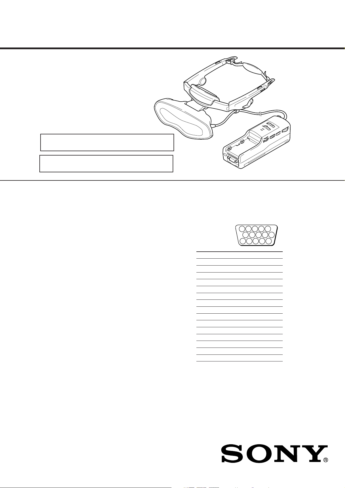
LDI-D100BE
SERVICE MANUAL
注:“4.ダイヤグラム”は,別冊(9-928-116-41)に記載さ
れています。
NOTE : “SECTION 4 DIAGRAMS” is provided in the sepa-
rate manual (9-928-116-41).
SPECIFICATIONS
Power supply
AC power adapter: AC-PLM3
100-240 V AC, 50/60 Hz, 16 W
Output voltage 8.4 V, 1.6 A
Battery pack: NP-F550/F750/F950
Power consumption
Operating temperature
Storage temperature
Dimensions
Mass
Video signal
(not supplied)
10 W (approx., PC mode)
12 W (approx., VIDEO mode)
41°F to 95°F (5°C to 35°C)
14°F to 140°F (–10°C to 60°C)
Display unit:
Approx. 5
(Approx. 149 × 48 × 86 mm)
(w/h/d folded)
Power supply box:
Approx. 2
(Approx. 54 × 47 × 160 mm)
(w/h/d)
not including projecting parts and
controls
Display unit: Approx. 4.2 oz. (120 g)
Power supply box: Approx. 9.2 oz. (260 g)
PAL color, CCIR standards
7
/8 × 1 15/16 × 3 1/2 inches
1
/4 × 1 7/8 × 6 3/8 inches
VIDEO Input
PC mode
RGB signal: HD15
Pin Assignment
Pin No. Signal
1 R (Red)
2 G (Green)
3 B (Blue)
4
5 GND
6 R (Red) GND
7 G (Green) GND
8 B (Blue) GND
9
10 GND
11 GND
12 –
13 SYNC (Horizontal)
14 SYNC (Vertical)
15 –
–
–
5 4 3 2 1
8 7 6
10 9
15 14 13 12 11
PAL Model
9-928-116-01
– Continued on next page –
パーソナルLCDディスプレイ
PERSONAL LCD DISPLAY

VIDEO mode
S VIDEO input: 4-pin mini DIN
Y: 1 Vp-p, 75 ohms, unbalanced, sync
negative
C: 0.286 Vp-p, 75 ohms, unbalanced,
sync negative
AUDIO input
Stereo miniplug
CONTROL input connector (used in PC
mode
only)
Special type stereo miniplug
Screen resolution
Horizontal: 832 dots (max.)
Vertical: 624 lines (max.)
Supplied accessory
AC power adapter: AC-PLM3 (1)
Power cords (2)
Design and specifications are subject to
change without notice.
Notes on chip component replacement
• Never reuse a disconnected chip component.
• Notice that the minus side of a tantalum capacitor may be damaged by heat.
サービス,点検時には次のことにご注意下さい。
1. 注意事項をお守りください。
サービスのとき特に注意を要する個所については,キャ
ビネット,シャーシ,部品などにラベルや捺印で注意事
項を表示しています。これらの注意書き及び取扱説明書
等の注意事項を必ずお守り下さい。
2. 指定部品のご使用を
セットの部品は難燃性や耐電圧など安全上の特性を
持ったものとなっています。従って交換部品は,使用さ
れていたものと同じ特性の部品を使用して下さい。特に
回路図,部品表に
品は必ず指定のものをご使用下さい。
3. 部品の取付けや配線の引きまわしはもとどおりに
安全上,チューブやテープなどの絶縁材料を使用した
り,プリント基板から浮かして取付けた部品がありま
す。また内部配線は引きまわしやクランパによって発熱
部品や高圧部品に接近しないよう配慮されていますの
で,これらは必ずもとどおりにして下さい。
4. サービス後は安全点検を
サービスのために取外したネジ,部品,配線がもとどお
りになっているか,またサービスした個所の周辺を劣化
させてしまったところがないかなどを点検し,安全性が
確保されていることを確認して下さい。
5. チップ部品交換時の注意
• 取外した部品は再使用しないで下さい。
• タンタルコンデンサのマイナス側は熱に弱いため交
換時は注意して下さい。
6. フレキシブルプリント基板の取扱いについて
• コテ先温度を270℃前後にして行なって下さい。
• 同一パターンに何度もコテ先を当てないで下さい。
(3回以内)
• パターンに力が加わらないよう注意して下さい。
7. 多層プリント基板の取扱いについて
できるだけプリント基板はねじれ,たわみのないように
取扱いして下さい。フラットパッケージIC等のハンダ付
けが取れることがあります。
0 印で指定されている安全上重要な部
Flexible Circuit Board Repairing
• Keep the temperature of the soldering iron around 270 ˚C during repairing.
• Do not touch the soldering iron on the same conductor of the
circuit board (within 3 times).
• Be careful not to apply force on the conductor when soldering
or unsoldering.
SAFETY-RELATED COMPONENT WARNING!!
COMPONENTS IDENTIFIED BY MARK 0 OR DOTTED
LINE WITH MARK 0 ON THE SCHEMATIC DIAGRAMS
AND IN THE PARTS LIST ARE CRITICAL TO SAFE
OPERATION. REPLACE THESE COMPONENTS WITH
SONY PARTS WHOSE PART NUMBERS APPEAR AS
SHOWN IN THIS MANUAL OR IN SUPPLEMENTS PUBLISHED BY SONY.
– 2 –

TABLE OF CONTENTS
1. 概要
GENERAL
パーソナルLCDディスプレイは,
新しいタイプの映像ディスプレイです ................. 1-1
パーソナルLCDディスプレイとは ......................... 1-1
各部のなまえ.............................................................. 1-1
接続する...................................................................... 1-1
装着する...................................................................... 1-4
見る .............................................................................. 1-4
外の様子を見る.......................................................... 1-5
調整する...................................................................... 1-5
別売りのバッテリーパックで使う.......................... 1-7
使用上のご注意.......................................................... 1-7
The Personal LCD Display is
a Brand-new Concept in Visual Display ..................... 1-8
About the Personal LCD Display ................................ 1-8
Locating the Parts and Controls .................................. 1-8
Connecting the Personal LCD Display ....................... 1-9
Wearing the Personal LCD Display ............................ 1-11
Using the Personal LCD Display ................................ 1-11
Viewing the Surrounding Environment ....................... 1-12
Adjusting the Sound and Picture ................................. 1-12
Using the Optional Battery Pack ................................. 1-14
Precautions ................................................................... 1-14
2. 外し方
DISASSEMBLY ...................................................... 2-1
3. 電気調整 .................................................................... 3-1
ELECTRICAL ADJUSTMENTS...................... 3-16
4. ダイヤグラム(別冊:9-928-116-41)
DIAGRAMS (Separate Volume: 9-928-116-41)
4-1. Block Diagram – AUDIO/VIDEO Section – ............. 4-1
4-2. Block Diagram
– A/D, D/A, OSD, SYNC Section –............................ 4-5
4-3. Block Diagram
– GAMMA CONTROL/LCD DRIVE Section – ........ 4-7
4-4. Block Diagram
– MODE CONTROL/SENSOR/LCS Section – ......... 4-9
4-5. Block Diagram – POWER SUPPLY Section –.......... 4-11
4-6. プリント図,回路図共通ノート
Note for Printed Wiring Boards and
Schematic Diagrams .................................................... 4-14
4-7. Printed Wiring Board – JK-136 (F) Board – .............. 4-15
4-8. Schematic Diagram – JK-136 (F) Board – .................. 4-16
4-9. Schematic Diagram – YC-148 (F) Board (1/3) – ........ 4-17
4-10. Schematic Diagram – YC-148 (F) Board (2/3) – ........ 4-19
4-11. Schematic Diagram – YC-148 (F) Board (3/3) – ........ 4-24
4-12. Printed Wiring Board – YC-148 (F) Board – ............. 4-27
4-13. Printed Wiring Board – MA-324 (F) Board – ............ 4-30
4-14. Schematic Diagram – MA-324 (F) Board (1/7) – ....... 4-33
4-15. Schematic Diagram – MA-324 (F) Board (2/7) – ....... 4-37
4-16. Schematic Diagram – MA-324 (F) Board (3/7) – ....... 4-41
4-17. Schematic Diagram – MA-324 (F) Board (4/7) – ....... 4-44
4-18. Schematic Diagram – MA-324 (F) Board (5/7) – ....... 4-47
4-19. Schematic Diagram – MA-324 (F) Board (6/7) – ....... 4-51
4-20. Schematic Diagram – MA-324 (F) Board (7/7) – ....... 4-53
4-21. Printed Wiring Board – LC-61 (F) Board – ............... 4-55
4-22. Schematic Diagram – LC-61 (F) Board – ................... 4-57
4-23. Printed Wiring Board – SW-306 (F) Board –............. 4-60
4-24. Schematic Diagram – SW-306 (F) Board – ................ 4-63
4-25. Printed Wiring Board – DD-107 (F) Board – ............ 4-65
4-26. Schematic Diagram – DD-107 (F) Board – ................ 4-67
5. ICダイヤグラム
IC DIAGRAMS
5-1. IC Block Diagrams ...................................................... 5-1
5-2. IC Pin Function Description ........................................ 5-11
6. 分解図
EXPLODED VIEWS ............................................. 6-1
7. 電気部品表
ELECTRICAL PARTS LIST ............................ 7-1
– 3 –
1. 概 要
1-1
1-2
1-3
1-4
1-5
1-6
1-7
SECTION 1
GENERAL
The Personal LCD Display is a brand-new
concept in visual display
Congratulations on your purchase of the
Sony Personal LCD Display. The Personal
LCD Display using current technology in
small, lightweight visual displays, provides
a television viewing experience similar to
watching a 30-inch television from a
distance of approximately 4 feet in SVGA
mode. (Viewing experience may differ
according to individual perception.)
The Personal LCD Display creates an image
through two separate liquid crystal
displays, in close proximity to your eyes.
To insure your safe use of the Personal LCD
Display, please become familiar with its
basic operations, including proper fitting
instructions, and be aware of any symptoms
of eye fatigue or other discomfort you may
experience.
3D Stereoscopic pictures
You can enjoy 3D (3-dimensional)
stereoscopic pictures by using video signals
that are already processed to compensate
for parallax. The Personal LCD Display
switches these optimized pictures for each
eye using a frame sequential method (field
sequential in the S-Video input) to display
the 3D stereoscopic pictures.
• In PC mode, you can select the display
mode between 2D (normal pictures) and
3D stereoscopic.
• In Video mode, only the signal input to
the S-Video connector is available, and
the display mode is fixed to 3D
stereoscopic mode.
•IBM PC/AT and VGA are registered trademarks of IBM Corporation of the U.S.A.
•Microsoft, MS, MS-DOS and Windows
United States and other countries.
•Macintosh is a trademark licensed to Apple Computer, Inc., registered in the U.S.A. and other
countries.
•VESA is a trademark of Video Electronics Standard Association.
•All other product names mentioned herein may be the trademarks or registered trademarks of
their respective companies. Furthermore, “” and “ " are not mentioned in each case in this
manual.
-US
4
WARNING
YOUR FAILURE TO FOLLOW THESE
OPERATING INSTRUCTIONS AND THE
SUPPLIED IMPORTANT SAFEGUARDS
MAY RESULT IN EYE FATIGUE, EYE
IMPAIRMENT, OR OTHER EYE INJURY,
PROPERTY DAMAGE, OR DEATH.
WARNING
THIS PRODUCT SHOULD NOT BE USED
BY CHILDREN AGE 15 OR YOUNGER.
THE EYES OF CHILDREN ARE STILL
DEVELOPING AND MAY BE ADVERSELY
AFFECTED FROM USE OF THIS
Note on the LCD (Liquid Crystal
Display)
The LCD screen is made with highprecision technology. However, black
points or bright points of light (red, blue,
or green) may appear constantly on the
LCD screen. This is not a malfunction.
(Effective dots: more than 99.999%)
are registered trademarks of Microsoft Corporation in the
PRODUCT.
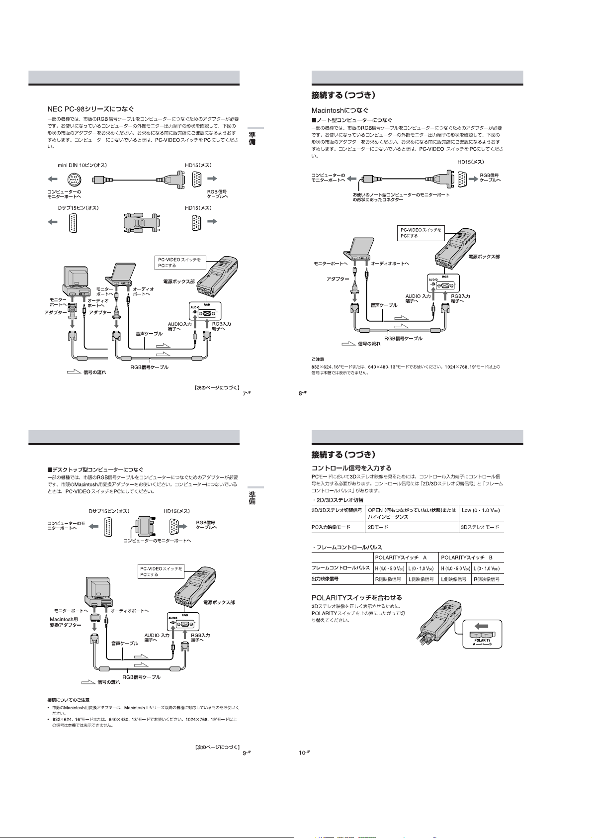
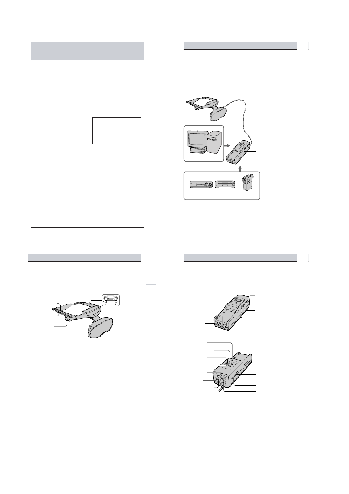
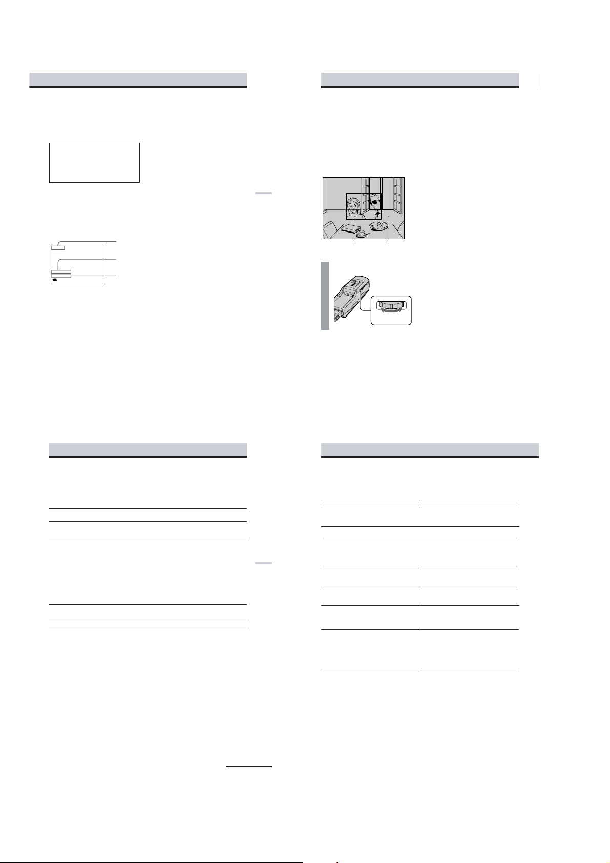
About the Personal LCD Display
Caution: The screen is always right in front of you.
The Personal LCD Display is a head-mounted display. With this type of display, the screen is
always in front of you even when you move your head. Because of this feature, you can
concentrate on the screen more easily compared with ordinary TVs, and you have a sense of
being in the action.
• It is easy to adjust the Personal LCD Display to your face and eyes. You can use the display
unit even while wearing glasses.
The Personal LCD Display consists of the following items:
Personal Computer
VCR Laser disc player Camcorder
Features
• A powerful, big screen experience comparable to
watching a 30-inch screen from approximately 4
feet (1.2 m) away (SVGA mode).
• You can connect the Personal LCD Display,
which is equipped with two 1.55 million dot
LCDs, to your PC to see the screen of the PC in
SVGA or VGA screen mode. You can also enjoy
3D stereoscopic pictures , as well as 2D pictures,
in SVGA or VGA screen mode.
-US
6
Display unit
The display unit is equipped with two small (left and right) LCDs.
Power supply box
You can supply power using the
supplied AC power adapter or the
optional Sony rechargeable battery
pack.
When using with the Personal LCD
Display, connect your video
equipment or PC to the connector
on the power supply
You can adjust the sound volume.
You can also use the SEETHROUGH control in order to see
the surrounding
• You can enjoy high quality 3D stereoscopic
pictures by connecting to video equipment such
as a digital camera recorder or a VCR.
• The see-through function allows you to see the
surrounding environment
Personal LCD Display.
• You can use the Personal LCD Display while
wearing glasses.
• Solid and lightweight
magnesium alloy, with the display unit
weighing about 5.3 oz. (120 g).
environment.
while
components
box.
wearing the
made of
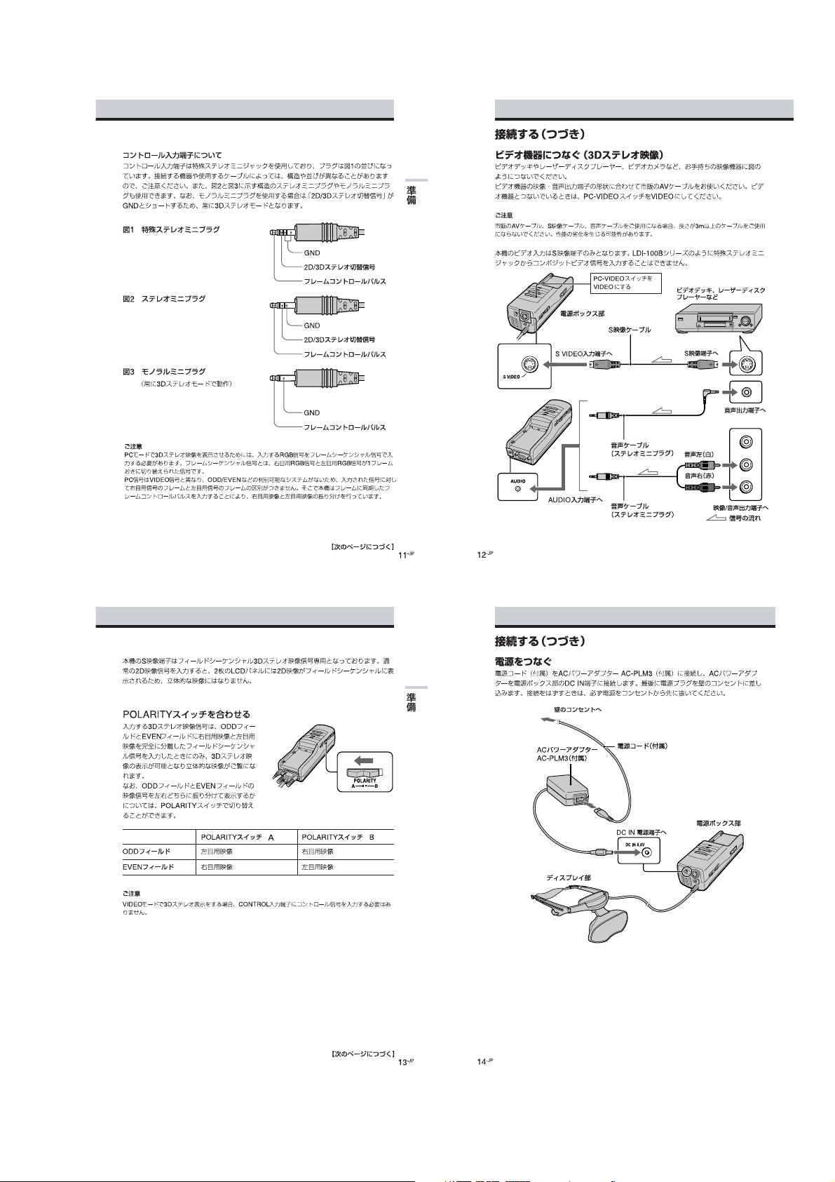
Locating the parts and controls
Refer to the pages indicated in parentheses ( ) for details.
Display unit
Strap release button (17)
Earphone slide button
(18)
Stereo earphone (18)
POWER SAVING SENSOR
(inner side) (24, 26)
continued
Locating the parts and controls (continued)
Getting Started
-US
7
Power supply box
RGB connector
(9 to 11, 36)
AUDIO connector
(9 to 11)
CHARGE lamp (29)
POWER/POWER SAVING
lamp (19, 26)
POWER switch (19)
PC-VIDEO switch
(9 to 14, 19)
S VIDEO connector
(14)
DC IN connector
(16)
Ventilation openings (33)
-US
8
PUSH DISPLAY jog dial (21, 25)
MENU button (25)
POLARITY switch (12, 15)
SEE-THROUGH control (22)
BATT RELEASE button (29)
BRIGHT control (20)
VOL control (20)
CONTROL connector (12, 13)
1-8
Connecting the P ersonal LCD Display
10
-US
AUDIO
RGB
Connecting the Personal LCD Display (continued)
Connecting a Macintosh Powerbook
Depending on the model, you may need to use a commercially available adapter to connect a
commercially available RGB signal cable as shown below. When you connect the Personal LCD
Display to your Powerbook, set the PC-VIDEO switch on the power supply box
to
“PC.”
VGA type connector
(HD15, female)
Connector should match the monitor
port of your Powerbook model.
to monitor
port of
Powerbook
to RGB
signal cable
<
Set the PC-VIDEO switch
to “PC.”
to monitor port to audio port
: Signal flow
RGB signal cable
to AUDIO
connector
to RGB connector
Audio cable
Adapter
Power supply box
Note on connection
Set the display setting to 16-inch display mode (832 × 624) or 13-inch display mode (640 ×
480).
The Personal LCD Display cannot display images with the 19-inch display mode (1024
× 768) setting or
more.
,
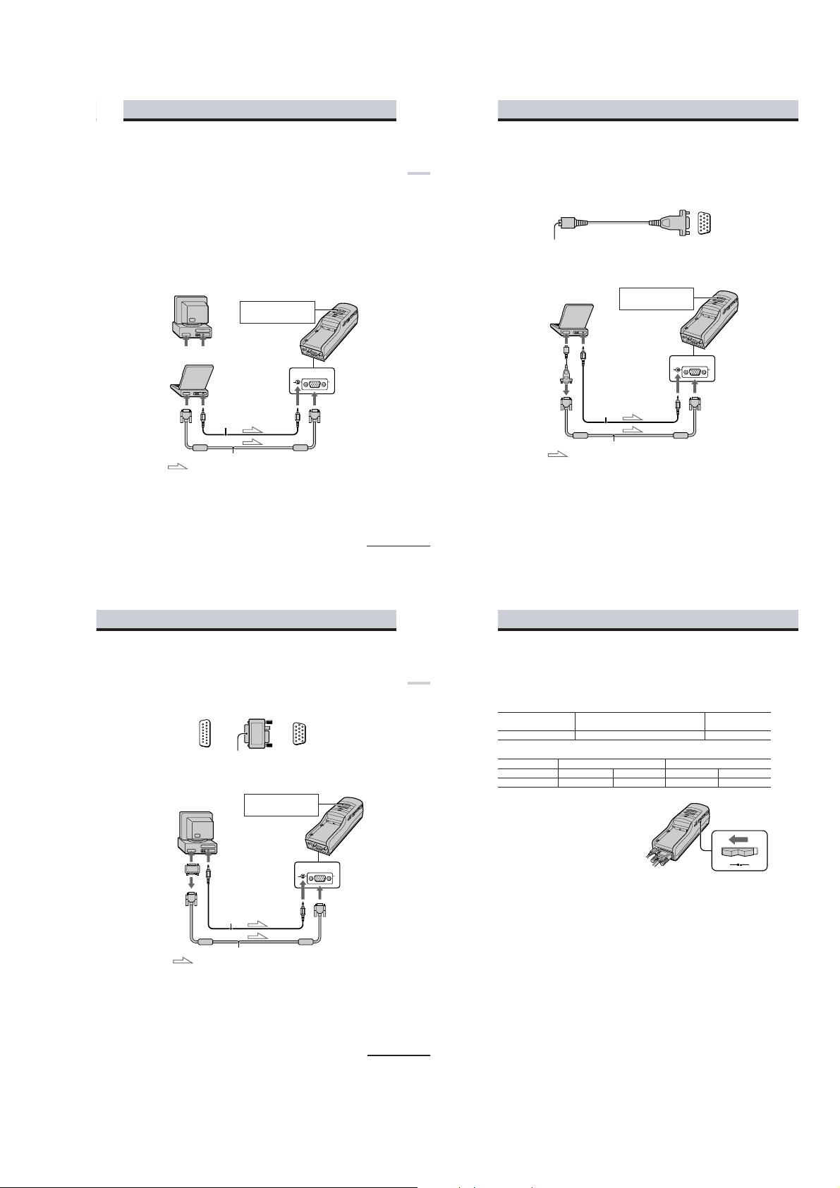
Connecting a PC
Be sure to turn off your PC before connecting the power supply box.
To enjoy 3D stereoscopic pictures, the control signal must be supplied to the CONTROL
connector. See a “Supplying the control signal” in page 12.
Notes
•Do not use an RGB signal cable (HD15) which is 6.5 feet (2 m) or longer. The performance may be
reduced.
•Refer to the instruction manual supplied with your PC as well.
•Depending on your computer, the audio port may be indicated as LINE OUT, headphone, speaker,
etc.
•Adjust sound volume on the computer.
Connecting other IBM compatible PCs
Connect the Personal LCD Display to your PC using a commercially available RGB signal
(HD15) cable. When you connect the Personal LCD Display to your PC, set the PC-VIDEO
switch on the power supply box to “PC.”
Set the PC-VIDEO switch
to “PC.”
Power supply box
Getting Started
to monitor port to audio port
to monitor port
Connecting a Macintosh (desktop models)
Depending on the model, you may need to use a commercially available Macintosh adapter to
connect a commercially available RGB signal cable as shown below. When you connect the
Personal LCD Display to your Macintosh, set the PC-VIDEO switch on the power supply box to
“PC.”
to monitor port
of Macintosh
to monitor port to audio port
or
: Signal flow
<
(D-Sub 15-pin,
male)
Macintosh
adapter
to audio port
Audio cable
RGB signal cable
to monitor
port
Audio cable
to AUDIO
connector
Set the PC-VIDEO switch
to “PC.”
to AUDIO
connector
RGB
AUDIO
to RGB connector
,
VGA type connector
(HD15, female)
Power supply box
RGB
AUDIO
to RGB connector
continued
to RGB signal cable
-US
9
Connecting the Personal LCD Displa y (continued)
Supplying the control signal
To enjoy 3D stereoscopic pictures in PC mode, the control signal must be supplied to the
Getting Started
CONTROL connector. There are two signals; “2D/3D stereoscopic control signal” and “frame
control pulse.”
• 2D/3D stereoscopic control signal
2D/3D stereoscopic OPEN (No connection) or high impedance Low (0 - 1.0 VDC)
control signal
PC mode
• Frame control pulse
Frame control pulse H (4.0 - 5.0 VDC) L (0 - 1.0 VDC) H (4.0 - 5.0 VDC) L (0 - 1.0 VDC)
Output video signal
Setting the POLARITY switch
To display the 3D stereoscopic pictures
correctly, set the POLARITY switch
according to the table above.
2D mode 3D stereoscopic mode
POLARITY switch A POLARITY switch B
Right side video signal Left side video signal Left side video signal Right side video signal
POLARITY
AB
Notes on connection
•Use a commercially available Macintosh adapter which suppors the models after the Macintosh II
series.
•Set the display setting to 16-inch display mode (832 × 624) or 13-inch display mode (640 × 480). The
Personal LCD Display cannot display images with the 19-inch display mode (1024 × 768) setting or
more.
: Signal flow
RGB signal cable
continued
-US
11
-US
12
1-9
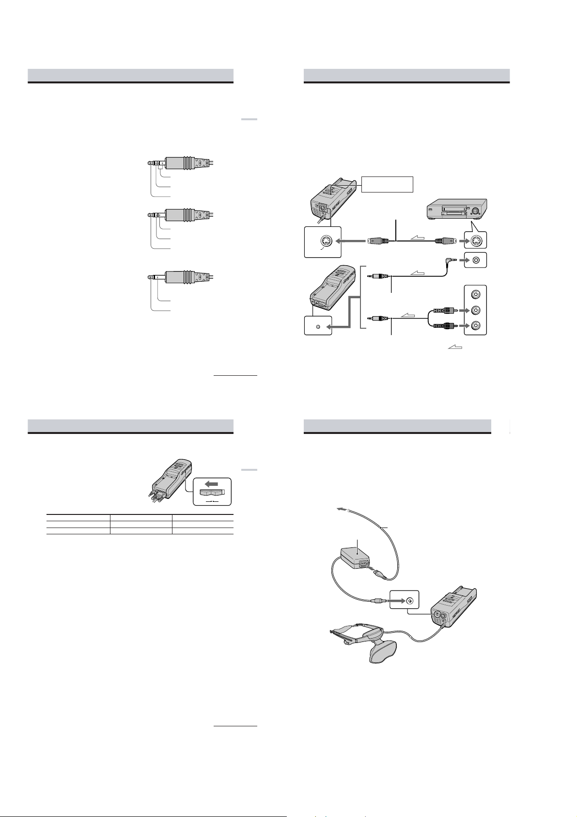
Notes on CONTROL connector
The CONTROL connector uses the special type of the stereo miniplug shown in Figure 1 below.
Note that the connector of the video equipment or video cables may differ from the CONTROL
terminal.
In addition to the special miniplug, you can also use a stereo miniplug or monaural miniplug
shown in Figures 2 and 3. If you use the monaural miniplug, note that the display mode will be
fixed to 3D stereoscopic mode because the GND and 2D/3D stereoscopic control signals are not
separated.
Figure 1 Special type stereo miniplug
GND
2D/3D stereoscopic control
signal
Frame control pulse
Figure 2 Stereo miniplug
GND
2D/3D stereoscopic control
signal
Frame control pulse
Figure 3 Monaural miniplug
(Fixed to 3D stereoscopic mode)
Connecting the Personal LCD Display (continued)
Connecting video equipment (3D stereoscopic picture)
Connect a VCR, laser disc player, or camcorder to the power supply box using a commercially
Getting Started
available audio/video cable as shown below. When you connect the Personal LCD Display to
the video equipment, set the PC-VIDEO switch on the power supply box to “VIDEO.”
Note
Do not use audio, audio/video, or S-video connecting cables, which are 9.8 feet (3 m) or longer. The
performance may be reduced.
You can use only the S-Video connector to enjoy the 3D stereoscopic picture from the video
equipment. You cannot input the composite video signal to the Personal LCD Display by using
the special type stereo miniplug, likewise with the LDI-100B series.
Set the PC-VIDEO switch
to “VIDEO. ”
Power supply box
S-video cable
to S VIDEO connector
S VIDEO
VCR, Laser disc player, etc.
to S-video output
to audio output
GND
Note
When you want to display 3D stereoscopic pictures in PC mode, the RGB signal in the frame sequential
format must be supplied to the Personal LCD Display. The frame sequential signal switches the frame
pictures for the right and left eyes alternately for each frame.
Since the RGB signal output from the PC does
ODD/EVEN information of the video signal, the system cannot distinguish which frame is processed
for the right eye and for the left eye. To distinguish frames, the Personal LCD Display uses a frame
control pulse synchronized with the frame transition.
Setting the POLARITY switch
You can enjoy 3D stereoscopic pictures only
when the following signal is supplied: field
sequential signals that completely separate
the pictures for the right and left eyes using
the ODD and EVEN sequential fields.
You can also set which field is for right (or
left) eye by setting the POLARITY switch.
ODD field For the left eye For the right eye
EVEN field For the right eye For the left eye
Note
To enjoy 3D stereoscopic pictures in VIDEO mode, you do not have to supply the control signal to the
CONTROL connector.
include frame identification information such
not
POLARITY switch A POLARITY switch B
Frame control pulse
continued
POLARITY
AB
as the
Audio cable
(stereo miniplug)
AUDIO
to AUDIO connector
The S-Video connector of the Personal LCD Display is designed only for supplying the field
sequential 3D stereoscopic picture signal. If a normal 2D video signal is supplied, the Personal
LCD Display simply displays
13
method, but 3D stereoscopic pictures will not appear.
-US
14
Audio cable
(stereo miniplug)
normal
2D pictures on each LCD panel in the field sequential
Audio L (white)
Audio R (red)
to audio/video outputs
: Signal flow
Connecting the Personal LCD Display (continued)
Connecting the power source
Connect the AC power adapter AC-PLM3 (supplied) to the DC IN connector on the power
Getting Started
supply box. Then, connect the AC power cord (supplied) to the AC power adapter and to a wall
outlet. Do not connect the power source until all other connections are complete.
to wall outlet
AC power adapter
AC-PLM3 (supplied)
AC power cord (supplied)
continued
to DC IN connector
Display unit
-US
15
-US
16
DC IN 8.4V
Power supply box
1-10
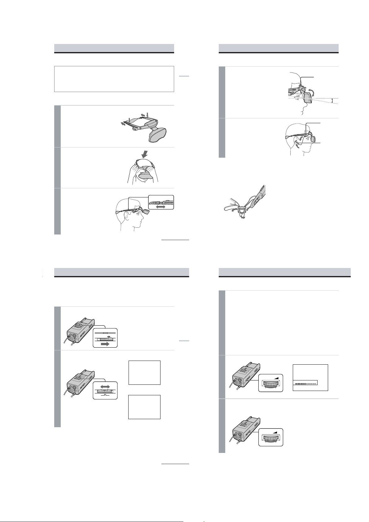
Wearing the Personal LCD Display
20
-US
Using the Personal LCD Display (continued)
3
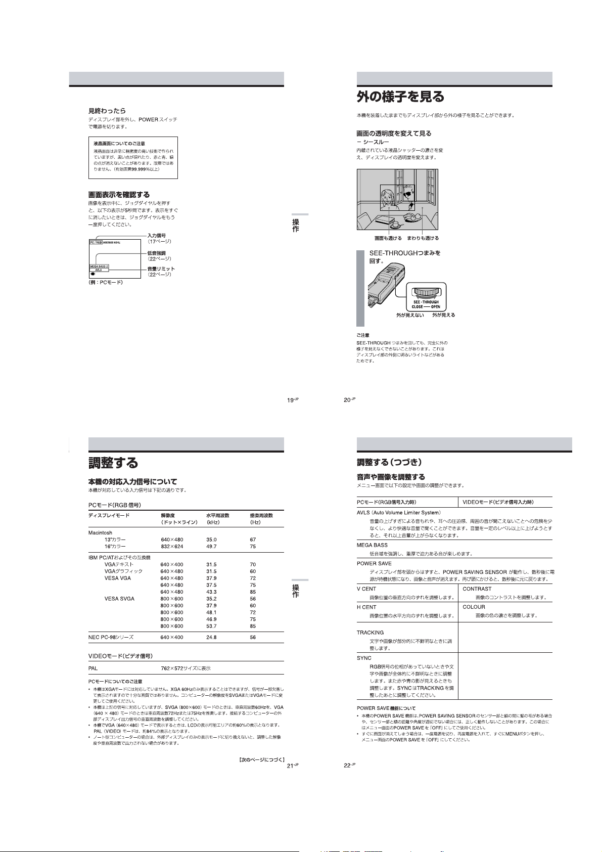
Input the signal from the connected equipment.
When you connect the PC:
Adjust the screen resolution. For details, see “Signal compatibility” on page 23.
When you display VGA pictures (640 × 480), the picture appears about 60% of the entire
screen.
Notes
•If no picture appears, check the default setting of your PC to output the external RGB signal
from the monitor connector.
•Some PCs do not output external display signal when they turn on, or switch to external
display mode. Change the display mode of your PC, referring to the instruction manual
supplied with your PC.
When you connect the video equipment:
Start playback on the video equipment connected to the Personal LCD Display.
When you display NTSC video picture, the picture appears about 60% of the entire
screen. For PAL video picture, the picture appears about 84% of the entire screen.
4
Adjust the brightness by
turning
the BRIGHT control.
5
Adjust the sound volume by turning the VOL control.
When you set AVLS (Auto Volume Limiter System) in the menu to on, you cannot turn
up the volume beyond the defined limit (see page 24 ). If the audio input level is too high,
the sound may be distorted. Turn the volume down using the VOL control.
darker y brighter
lower y louder
BRIGHT
BRIGHTNESS
VOL
WARNING
• Failure to properly fit the
of visual functions and may result in accident or injury.
• This product should not be used by children age 15 or younger.
The eyes of children are still developing and may be adversely affected by use of this
product, and it may cause eye fatigue, eye damage, or loss of visual functions.
In addition, this product may not be adjusted to fit a child’s head.
If you normally wear glasses while watching TV, you can use the Personal LCD Display while
wearing glasses.
Loosen the back strap.
1
1 Press and hold the strap release
buttons.
2 Then, loosen the back strap in the
direction of the arrows.
Put on the Personal LCD Display.
2
Hold the
front
forehead and place the rear strap so it is
fixed firmly around the back of your
head.
Adjust the strap.
3
Adjust the strap after putting on the
Personal LCD Display.
Make sure the strap is snug but
comfortable.
each time may result in eye fatigue, eye damage, or loss
product
2
pad against your
1
2
1
continued
Wearing the Personal LCD Display (continued)
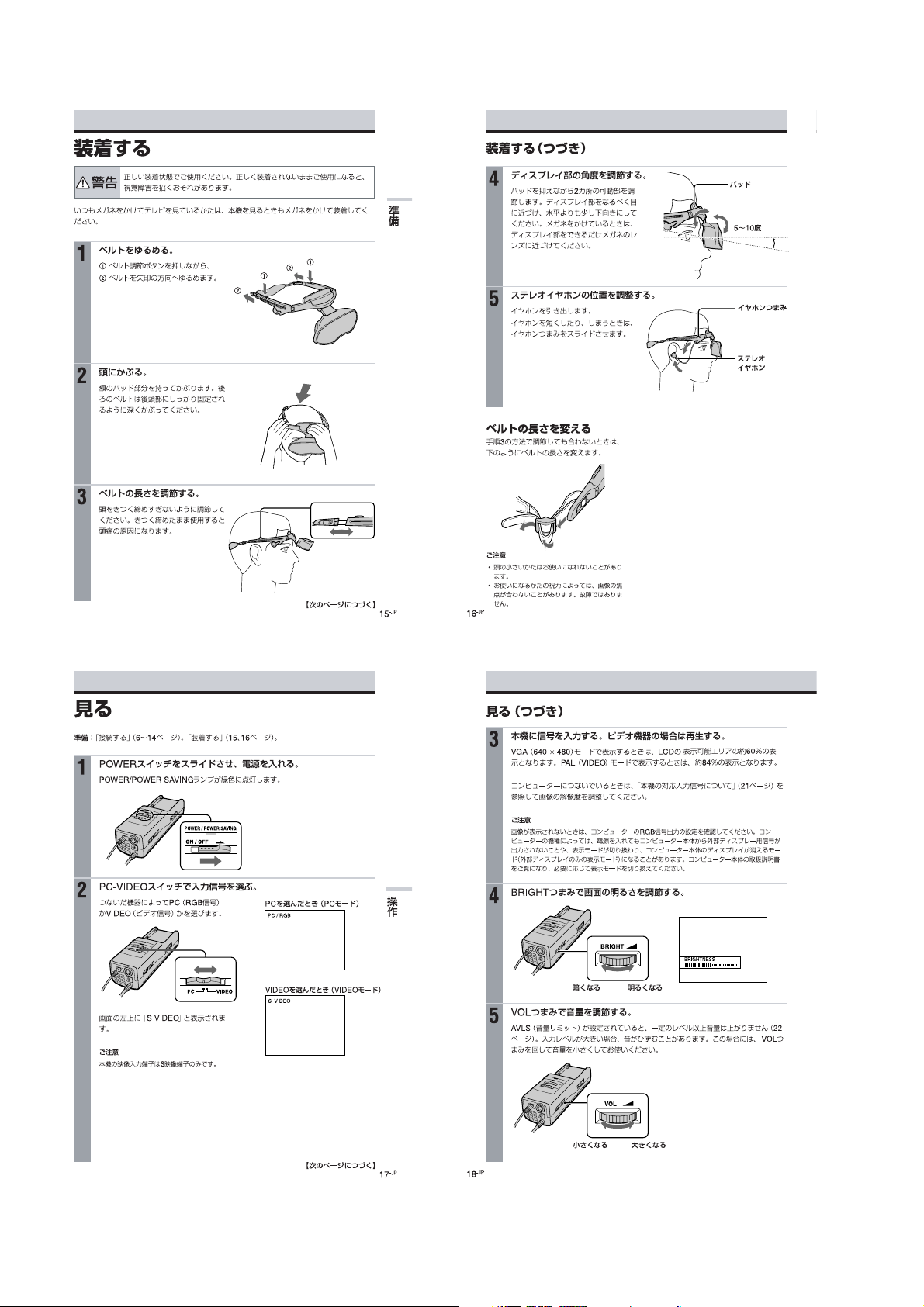
Adjust the angle of the display unit.
4
Getting Started
-US
17
While holding the front pad against
your forehead, adjust the angle of the
display unit using the two hinges. Move
the display unit close to your eyes
slight downward angle. If you wear
glasses, move the display unit as close to
the lenses as possible.
Adjust the stereo earphones.
5
Pull the earphones out.
To adjust the slack, reel in the earphone
cord by pressing the slide button in the
direction of the arrow.
Adjusting the back strap
If the strap does not fit properly in step 3,
adjust the strap by changing the belt length.
-US
18
a
at
Front pad
5 – 10°
Earphones
slide button
Stereo
earphones
Using the Personal LCD Display
Before you start…
Be sure to follow the procedures in “Connecting the Personal LCD Display” (pages 9 to 16) and
“Wearing the Personal LCD Display” (pages 17 and 18).
Turn on the Personal LCD Display using the POWER switch.
1
The POWER/POWER SAVING lamp lights up green.
Select the input signal using the PC-VIDEO switch.
2
Select PC (RGB signal) or VIDEO (video
signal) depending on the connected
equipment.
“S VIDEO” appears on the screen.
Note
Only the S-Video connector is available to
input the video signal to the Personal LCD
Display.
POWER / POWER SAVING
ON / OFF
PC
VIDEO
When you select PC (PC mode)
PC / RGB
When you select VIDEO
(Video mode)
S VIDEO
continued
19
Operations
-US
1-11
After you finish using the
Personal LCD Display
Take off the Personal LCD Display, and
turn off the power.
Note on the LCDs
The LCD screen is made with highprecision technology. However, black
points or bright points of light (red, blue, or
green) may appear constantly on the LCD
screen. This is not a malfunction.
(Effective dots: more than 99.999%)
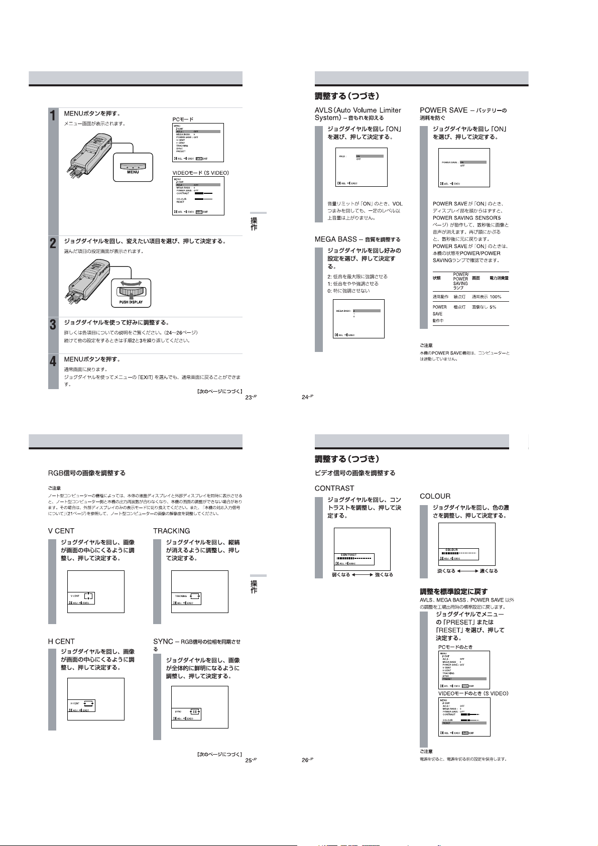
Checking the display
indications
Press the PUSH DISPLAY jog dial while the
picture is displayed. The display indication
appears on the screen for five seconds.
To turn off the indication sooner, press the
jog dial again.
PC / RGB 800X600 60Hz
MEGA BASS 2
AVLS
Input signal
(page 19)
MEGA BASS
(page 26)
AVLS
(page 26)
Operations
Viewing the surrounding environment
While you are wearing the Personal LCD Display, you can view the surrounding environment
through the screen:
Viewing the surrounding
environment by adjusting the
transparency of the entire
screen (See-through mode)
You can adjust the level of transparency of
the entire screen with the LCD shutter dial.
The picture becomes
transparent.
Turn the SEE-THROUGH dial.
Note
If there is a bright light near the display unit,
you may not be able to completely black out
the surrounding environment by adjusting the
SEE-THROUGH dial.
The area surrounding
the picture also becomes
transparent.
SEE - THROUGH
y
CLOSE OPEN
Adjusting the sound and picture
Signal compatibility
The signal specifications that this unit supports are as follows:
PC mode (RGB signal)
Display mode Screen resolution Horizontal Vertical
Macintosh
13” color 640 × 48 0 35.0 67
16” color 832 × 62 4 49.7 75
IBM PC compatibles
VGA text 640 × 400 31.5 70
VGA graphics 640 × 480 31.5 60
VESA VGA 640 × 480 37.9 72
VESA SVGA 800 × 600 35.2 56
Video mode (video signal)
PAL color system Displayed in 762 × 572 area
Notes on the PC mode
•This unit does not support XGA mode (1,024 × 768) and above. If you set the vertical frequency to 60
Hz in XGA mode, the picture is displayed but the picture quality is poor due to the signal loss.
Change the screen resolution on your PC to SVGA or VGA.
•Though the Personal LCD Display supports the signals listed above, set the vertical frequency to 60
Hz when using with SVGA (800 × 600), or to 72 Hz or 75 Hz
the vertical frequency of the external display output signal of the connected computer.
•When you display VGA pictures (640 × 480), the pictures are
pictures (video mode), about 84% of the screen area is utilized.
•Some notebook type PCs do not output the RGB signal in the adjusted screen resolution and the
vertical frequency from the external monitor port until you set the PC to external display mode.
(dot × line) frequency (kHz) frequency (Hz)
640 × 480 37.5 75
640 × 480 43.3 85
800 × 600 37.9 60
800 × 600 48.1 72
800 × 600 46.9 75
800 × 600 53.7 85
with
VGA (640 × 480) mode. Also adjust
About 60% of the screen area is utilized. For PAL video
not displayed across the entire screen.
-US
21
Operations
-US
22
Adjusting the sound and picture (continued)
Adjusting the sound/picture
You can adjust the following items using the menu display.
PC mode (RGB signal) Video mode (video signal)
AVLS (Auto Volume Limiter System):
Keeps the maximum volume down to protect your
beyon d the defined limit even if you try to turn the VOL control.
MEGA BASS:
Creates a deep, powerful sound by emphasizing the bass sound.
POWER SAVE:
The POWER SAVING SENSOR detects the removal of the Personal LCD Display from your
head. The unit enters standby mode in a few seconds, automatically stopping the sound and
picture in order to save the battery power. The sound and picture resume after a few seconds
when you put on the Personal LCD Display again.
V CENT:
Adjusts the vertical position of the
picture.
H CENT:
Adjusts the horizontal position of
the picture.
TRACKING:
Adjusts the tracking of the picture
(e.g., if the picture is not displayed
clearly).
SYNC:
Adjusts the picture with the RGB
signal synchronization (e.g., if the
picture is blurred, or if red or blue
shadows appear in the picture).
Perform this adjustment after
TRACKING adjustment is finished.
Notes on power saving function
•The power saving function may not work correctly in the following cases:
– your hair is between your forehead and the POWER SAVING SENSOR.
– the space or angle between your forehead and the POWER SAVING SENSOR is not correct.
In these cases, set POWER SAVE to OFF.
•When the picture disappears suddenly, do the following procedures:
1 Turn off the power sliding the POWER switch.
2 Turn on the power again.
3 Press MENU to display the menu options.
Set POWER SAVE to OFF.
4
ear. You cannot turn
CONTRAST:
Adjusts the picture contrast.
COLOUR:
Adjusts the color intensity.
up
the volume
continued
-US
23
-US
24
1-12
28
-US
Note
The settings are retained even when you turn
off the power.
Resetting the
adjustments to the
factory preset level
All settings except AVLS, MEGA BASS, and
POWER SAVE settings are reset to the
factory preset level.
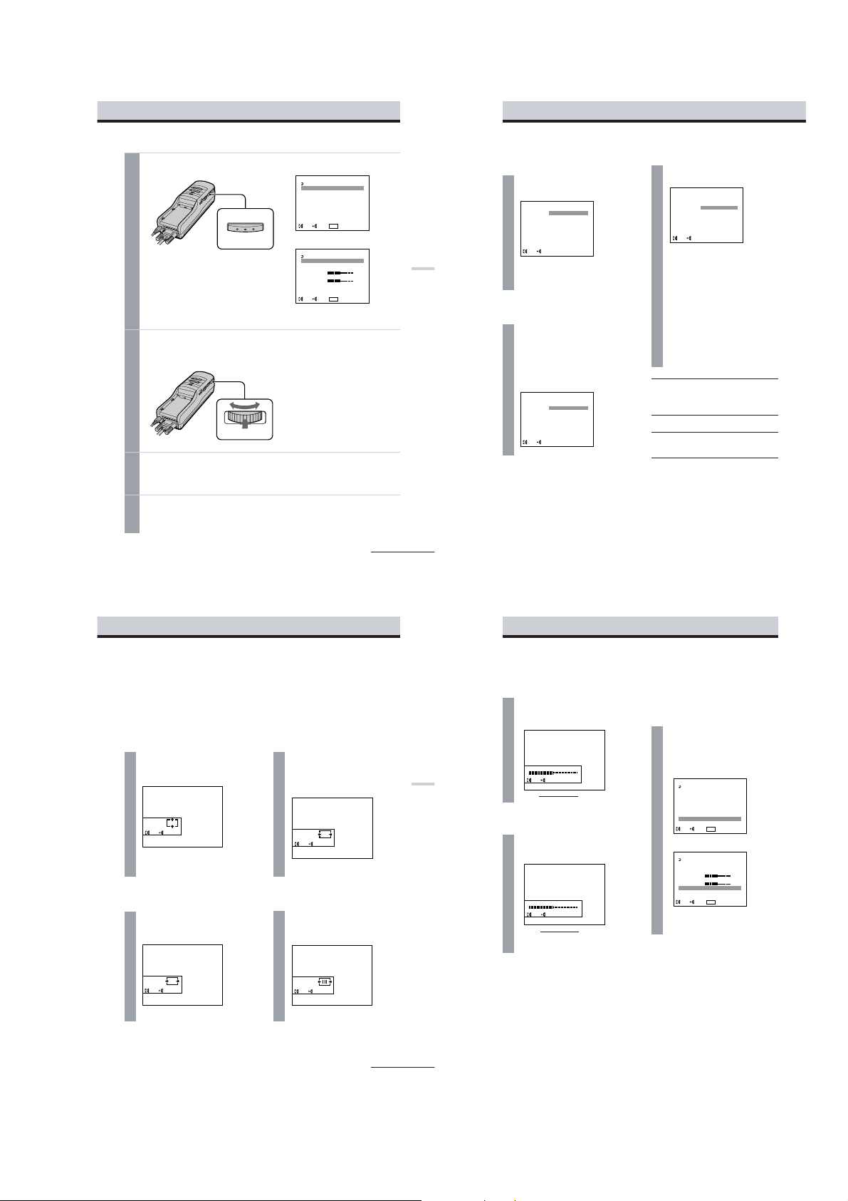
Turn the jog dial to select
PRESET or RESET in the
menu, then press the jog
dial.
CONTRAST
Turn the jog dial to adjust
the contrast, then press the
jog dial.
COLOUR
Turn the jog dial to adjust
the color intensity, then
press the jog dial.
Adjusting the video signal
less more
b
B
less more
b
B
PC mode
CONTRAST
EXECADJ
COLOUR
EXECADJ
MENU
EXIT
AVLS :
MEGA BASS :
POWER SAVE :
V CENT
H CENT
TRACKING
SYNC
PRESET
EXEC
SEL EXIT
MENU
0
OFF
OFF
MENU
EXIT
AVLS :
MEGA BASS :
POWER SAVE :
CONTRAST
COLOUR
RESET
EXEC
SEL EXIT
MENU
OFF
0
OFF
Adjusting the sound and picture (continued)
VIDEO mode (S VIDEO)
Press MENU.
26
-US
Adjusting the sound and picture (continued)
AVLS (A uto Volume Limiter
System)
Turn the jog dial to set to
ON, then press the jog dial.
When AVLS is on, the volume does
not become louder than the level you
set even if you turn the VOL control.
MEGA BASS
Turn the jog dial to select
the desired value, then
press the jog dial.
2: Maximize the bass sound.
1: Boost the bass sound.
0: Normal bass sound.
POWER SAVE
Turn the jog dial to set to
ON, then press the jog dial.
When you take off the display unit
while the POWER SAVE is set to ON,
the POWER SAVING SENSOR (page
7) is activated and automatically
turns off the picture and sound. The
picture and sound resume a few
seconds after putting the display unit
back on.
When POWER SAVE is set to ON,
you can monitor the status of the
Personal LCD Display by checking
the POWER/POWER SAVING
indicator.
Status
Normal
Power
save
mode
Note
The power saving function of the Personal
LCD Display works independently from the
power management function of your PC.
POWER/
POWER
SAVING
indicator
Lit in
green
Lit in
orange
Picture
Normal
No
picture
Power
consumption
100%
5%
ON
OFF
EXEC
SEL
AVLS :
POWER SAVE :
EXEC
SEL
ON
OFF
MEGA BASS :
EXEC
SEL
2
1
0
1
The menu display appears on the screen.
MENU
Turn the PUSH DISPLAY jog dial to select the desired item, then
2
press the jog dial.
The setting screen of the selected item appears.
PUSH DISPLAY
Adjust the setting using the jog dial.
3
For details on each item, see pages 26 to 28.
To set other items, repeat steps 2 and 3.
Press MENU.
4
The menu display goes off.
You can also turn off the menu display by selecting EXIT in the menu using the jog dial.
PC mode
MENU
EXIT
OFF
AVLS :
0
MEGA BASS :
POWER SAVE :
OFF
V CENT
H CENT
TRACKING
SYNC
PRESET
MENU
SEL EXIT
EXEC
VIDEO mode (S VIDEO)
MENU
EXIT
OFF
AVLS :
MEGA BASS :
0
POWER SAVE :
OFF
CONTRAST
COLOUR
RESET
MENU
EXEC
SEL EXIT
continued
25
Operations
-US
Adjusting the RGB signal
Note
When you display the picture on both the LCD display of the notebook PC and on the Personal LCD
Display, depending on the notebook PC, you may not be able to adjust the picture on the Personal LCD
Display due to the mismatch of the output signal frequencies. In this case, change the display mode on
your PC to the external monitor only. Then, change the screen resolution according to the list on
“Signal compatibility” (page 23).
V CENT
Turn the jog dial to adjust
the center of the picture,
then press the jog dial.
V CENT
H CENT
Turn the jog dial to adjust
the center of the picture,
then press the jog dial.
H CENT
EXECADJ
EXECADJ
TRACKING
Turn the jog dial until the
stripes on the picture
disappear, then press the
jog dial.
TRACKING
SYNC
Turn the jog dial to adjust
the clearance of the picture,
then press the jog dial.
SYNC
Operations
EXECADJ
EXECADJ
continued
27
1-13
Using the optional battery pack
DISPOSAL OF LITHIUM ION BATTERY.
LITHIUM ION BATTERY.
DISPOSE OF PROPERLY.
You can return your unwanted lithium ion batteries to
Factory Service Center.
NOTE: In some areas the disposal of lithium ion batteries in household or business trash may
prohibited.
Caution: Do not handle damaged or leaking lithium ion batteries.
If you use a battery pack such as the NP-F550/F750/F950, you can use the Personal LCD Display
without connecting
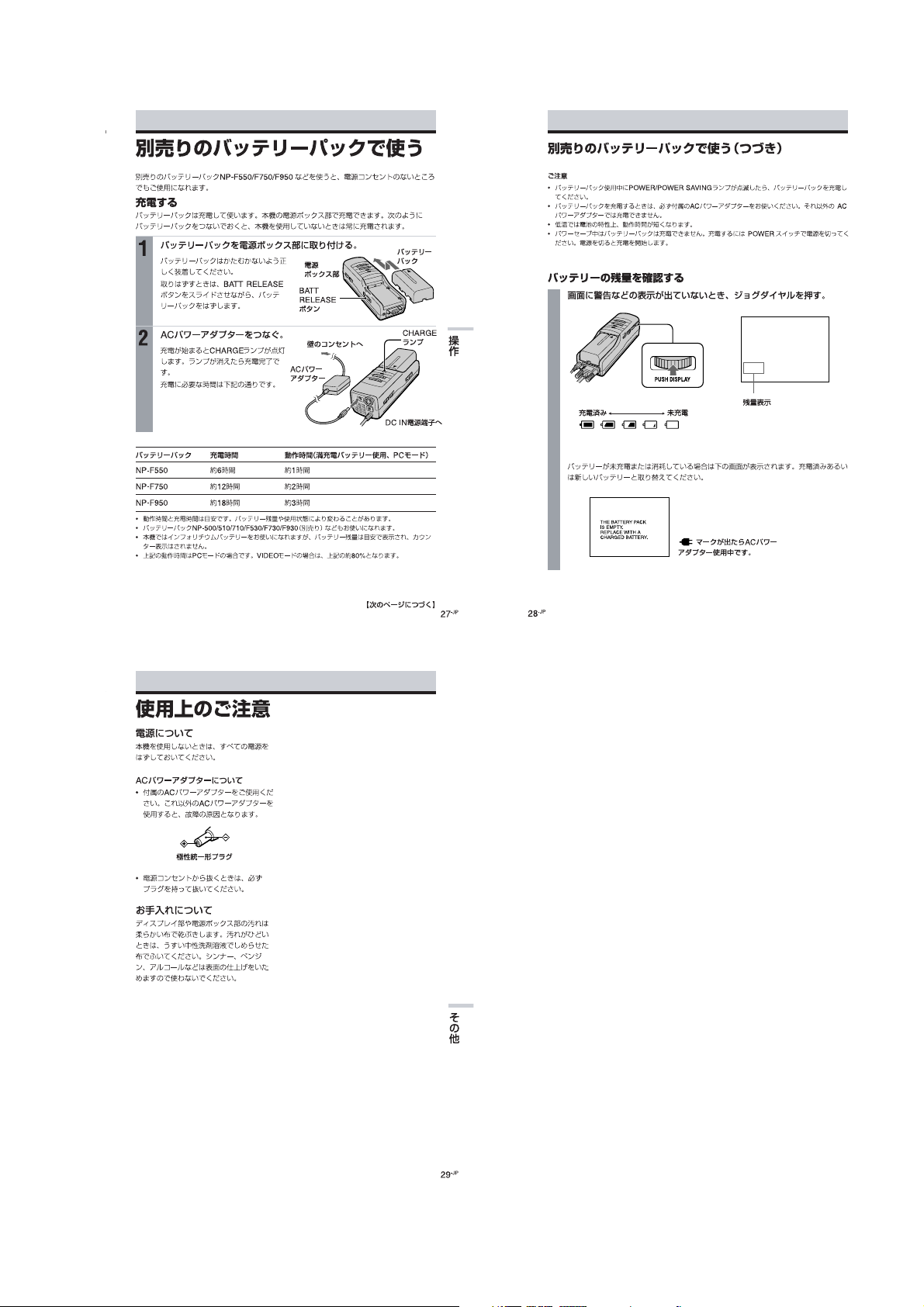
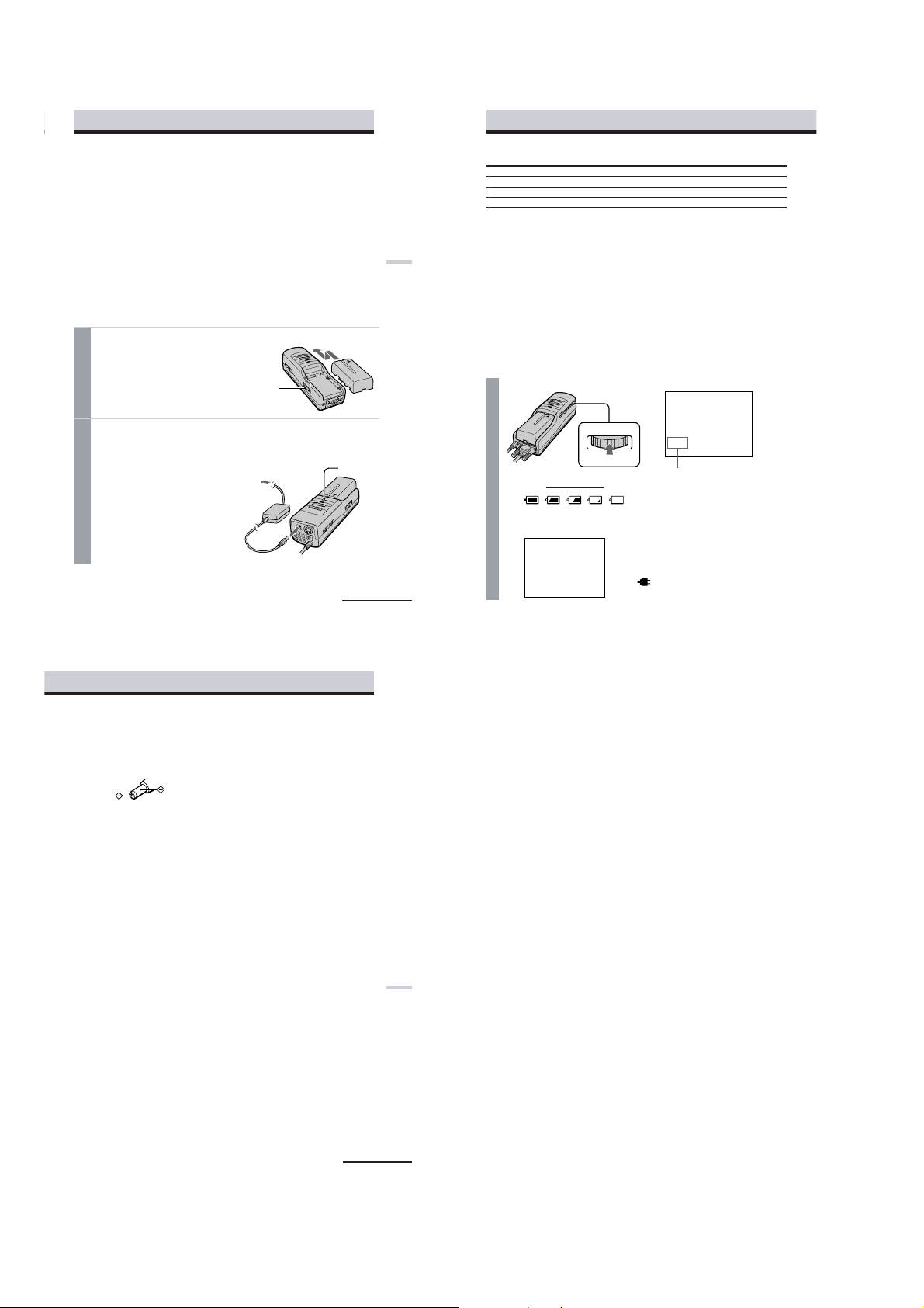
Charging the battery pac k
Charge the battery pack before use. You can charge the battery pack using the power
If you attach the battery pack as described below, the battery pack charges while you are not
using the Personal LCD Display.
1
2
to a wall outlet.
Attach the battery pack to the power supply box.
Install the battery pack properly making
sure it is not crooked against the power
supply box.
To remove the battery pack, while sliding
BATT RELEASE, pull out the battery
pack.
Connect the AC power adapter to the DC IN connector on the
power supply box. Then, connect the AC power cord to the AC
power adapter and to a wall outlet.
Charge the battery pack on a flat place
without vibration. The CHARGE lamp
lights up. When the battery pack is fully
charged, the CHARGE lamp goes out.
Battery life and charging time are shown
in the table below.
your nearest Sony Service Center or
Power supply
box
BATT RELEASE
button
to wall outlet
AC power
adapter
supply
Battery pack
CHARGE lamp
box.
Using the optional battery pack (continued)
Battery pack Charging time Battery life (fully charged battery, PC mode)
NP-F550 Approx. 6 hours Approx. 1 hour
NP-F750 Approx. 12 hours Approx. 2 hours
NP-F950 Approx. 18 hours Approx. 3 hours
•The battery life and charging time may change depending on the conditions of use.
be
Operations
•You can also use a battery pack such as the NP-500/510/710/F530/F730/F930 (not supplied) with
the Personal LCD Display.
•You can use an InfoLITHIUM™ battery pack with the Personal LCD Display. When using such a
battery pack, the estimated remaining battery life is displayed not with the time counter, but with the
indicator.
•The battery life listed above is for PC mode. When you use the Personal LCD Display in video mode,
the battery life is reduced to 80% of the PC mode.
“InfoLITHIUM” is a trademark of Sony Corporation.
Notes
•If the POWER/POWER SAVING lamp flashes while using the battery pack, charge the battery pack.
•Use the supplied AC power adapter only when charging a battery pack.
•Battery life may be shorter in a cold environment. This is a typical battery characteristic.
•You cannot charge the battery pack in power save mode. Turn off the Personal LCD Display, then it
starts charging the battery pack.
Checking the remaining battery life
When no indication or caution appears on the screen, press the jog dial.
PUSH DISPLAY
Fully
b
charged
When the battery pack is weak, the following message appears on the screen. Replace the
battery pack with a charged one.
b
dead
Remaining battery life
Precautions
Use
• Operate the product only with the
supplied AC power adapter. If you use a
different AC power adapter, it may cause
a malfunction.
Unified polarity plug
• Should any liquid or solid object fall into
the cabinet, unplug the product and have
it checked by qualified personnel before
operating it further.
• Always turn the product off when you do
not use it.
Unplug the product from the wall outlet if
you are not going to use it for several days
or more. To disconnect the cord, pull it
out by the plug. Never pull the cord itself.
• Do not overload wall outlet, extension
cords, or convenience receptacles beyond
their capacity, since this can result in fire
or electric shock.
• Do not use attachments not recommended
by the manufacturer, as they may cause
hazards.
• Avoid using earphones at high volume.
Hearing experts advise against
continuous, loud, and extended play. If
you experience a ringing in your ears,
reduce volume or discontinue use.
• Do not touch the AC power adapter or
power supply box with wet hands. If you
fail to observe this, it may cause electric
shock.
• Do not drop or give a mechanical shock to
the product.
to DC IN
continued
Installation
• To prevent internal heat build-up, do not
block the ventilation openings.
• Avoid operating the product at
temperatures below 41˚F (5˚C).
• Do not subject the product to high
temperature or direct sunlight. If you do
not observe the above instructions, the
product may become deformed and the
screens may become impossible to align.
If you keep watching misaligned screens,
you may develop eye fatigue. If you find
the screens misaligned, have the product
repaired at an authorized service center.
• Do not place the product in locations
where it is wet, humid, dusty, smoky, or
steamy. Do not use this product near or
around water. It may cause fire or
electric shock. Especially, do not use the
product in the bathroom.
• If the product is transported directly from
a cold to a warm location, or if the room
temperature has changed suddenly, the
picture may be blurred or show poor
color. This is because moisture has
condensed on the mirror or lenses inside.
If this happens, let the moisture
evaporate before using the product.
• Do not place the product on an unstable
cart, stand, table, or shelf. The product
may fall, causing serious injury to a child
or an adult, and serious damage to the
product.
• Do not allow anything to rest on or roll
over the power cord, and do not place the
product where the power cord is subject
to wear or abuse.
29
-US
Additional Information
THE BATTERY PACK
IS EMPTY.
REPLACE WITH A
CHARGED BATTERY.
-US
30
When using the AC power adapter,
the “
” mark appears on the
screen.
continued
-US
31
1-14
1-14 E
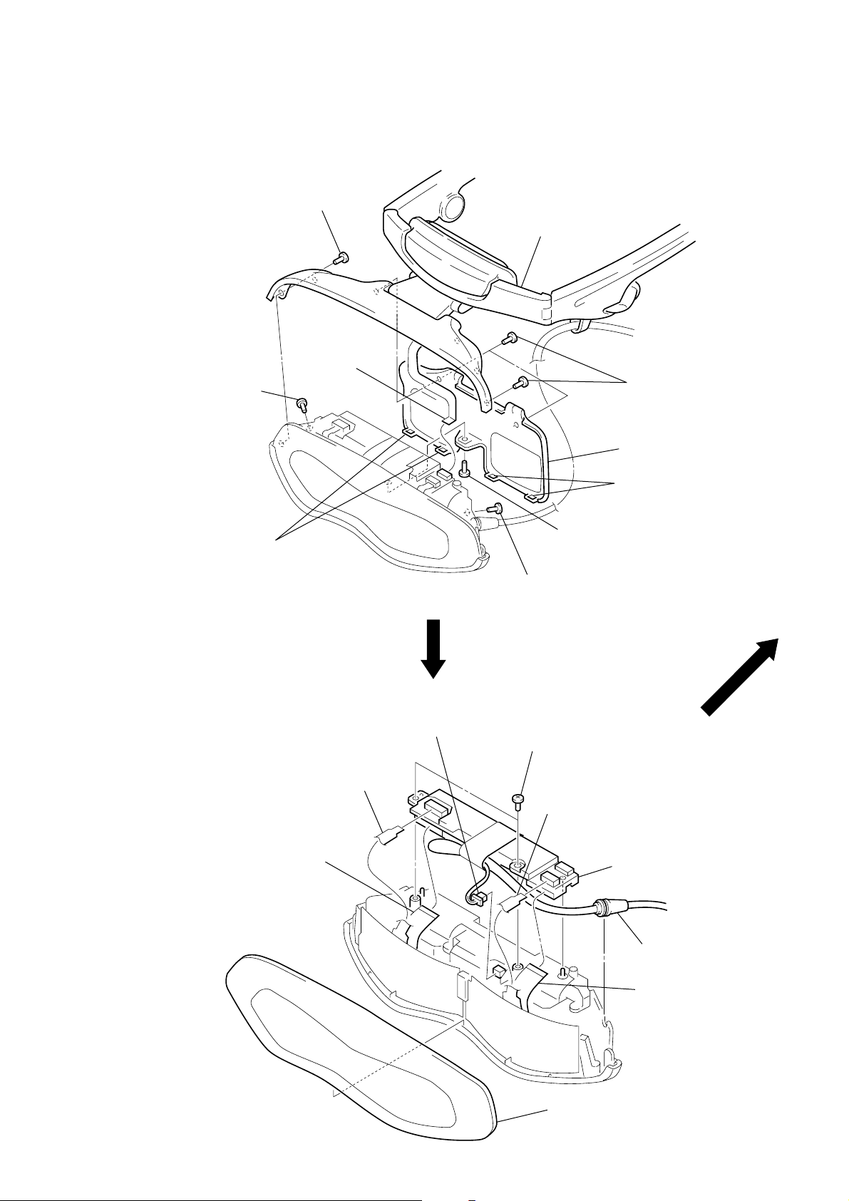
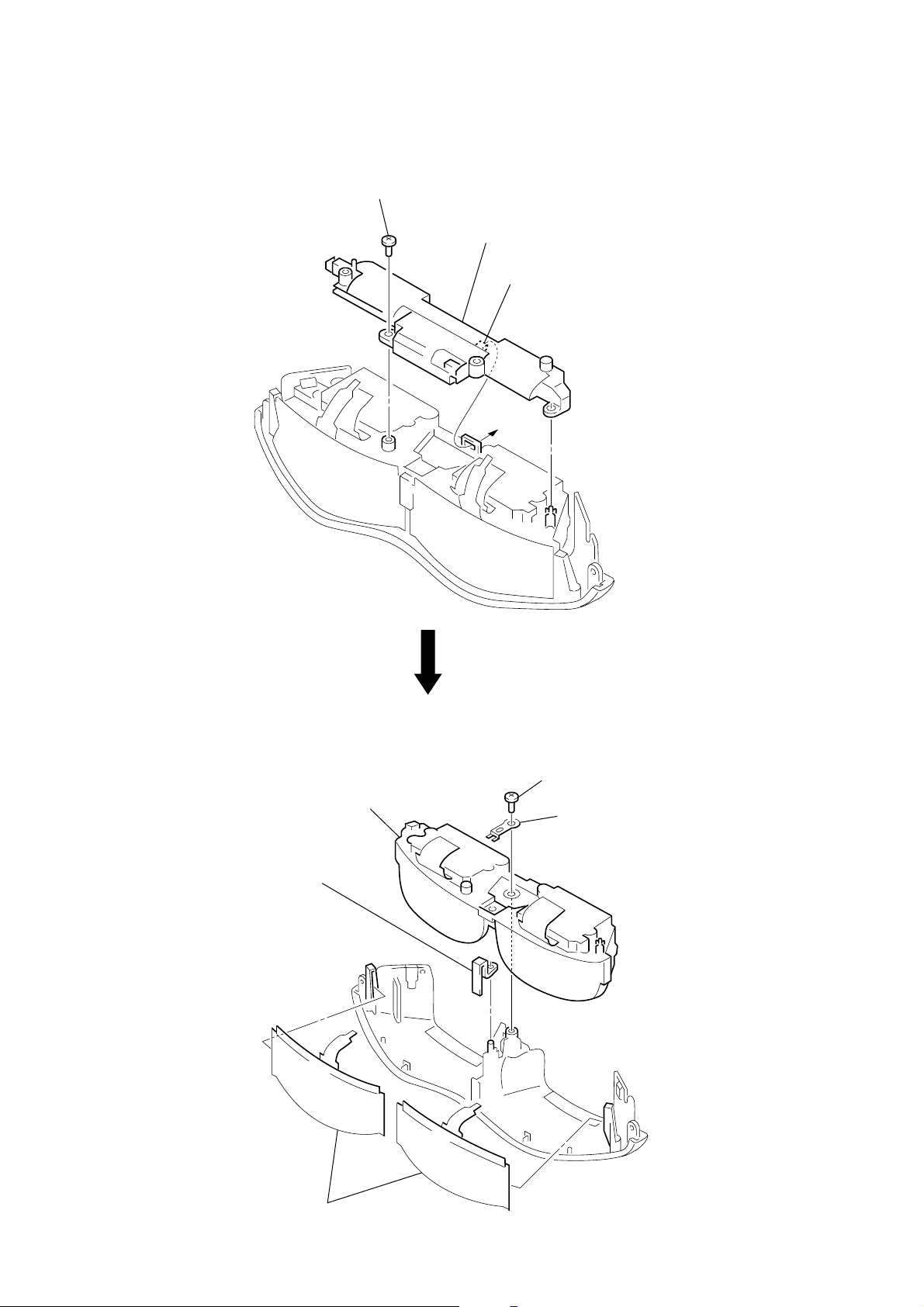
2. 外し方
SECTION 2 DISASSEMBLY
•図中に1など番号のあるものは,その番号順に外す。
Note: Follow the disassembly procedure in the numerical order given.
LOADING BLOCK ASSY
1
screw
(M1.4
×
3.0)
6
FP661 flexible
board (CN803)
1
screw
(M1.4
×
3.0)
2
loading block assy
1
three screws
(M1.4
×
5
rear cabinet assy
3.0)
LC-61(F) BOARD
4
two claws
7
flexible board
(CN805)
3
flexible board
(CN802)
2
connector
(back light unit)
1
screw
(M1.4
4
two screws
(M1.7 × 5)
3
3
screw
(M1.4
×
3.0)
×
3.0)
flexible board
(CN801)
6
4
two claws
LC-61 (F) board
2-1
1
front panel
5
connection cable
7
flexible board
(CN804)
BACK LIGHT UNIT
1
screw
(M1.7 × 5)
3
back light unit
2
claw
OPTICS BLOCK ASSY, FILM (PANEL) LIQUID CRYSTAL
3
optics block assy
4
shutter holder (C)
1
screw
(P1.7 × 4.0)
2
lens fixed plate
5
two film (panel) liquid crystals (C)
2-2 E
2-2
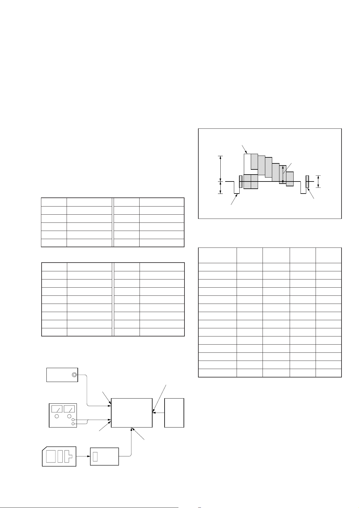
3. 電気調整
白(100%)
約0.3V
約0.7V
約0.3V
赤
バースト信号
(平坦なこと)
水平同期信号
【調整時の注意】
1. 調整は掲載順に行う。
2. 電源電圧:DC8.4V
3. 使用機器
電気調整には下記に示す測定器類を使用します。
(1) オシロスコープ2現象,帯域30MHz以上,ディレイモー
ド付(特に指定のない限り10:1のプローブを使用する
こと)
(2) パターンジェネレータ
(3) 安定化電源
(4) デジタルボルトメータ
(5) 周波数カウンタ
(6) 調整用コネクタ
(7) ケント紙(装着センサレベル調整で使用)
4. 調整のための測定点は,YM-148(F)基板のCN1003とMA-
324(F)基板のCN206にそれぞれ集中しています。下表に
CN1003およびCN206の端子番号と信号名称を記します。
• YC-148(F)基板 CN1003
端子番号 信号名称
1 GND
2 GND
3 GND
4 4FSC
5 GND
端子番号 信号名称
6 GND
7 YOUT
8 VIDEOG
9 N.C
10 GND
• MA-324(F)基板 CN206
端子番号 信号名称
1 SIGR1
2A
3 SIGG1
4 POWERSW
5 SIGB1
6 ENTER
7 INTH
8 VIDEO/XPCIN
端子番号 信号名称
9 GND
10 GND
11 B
12 COMR
13 C
14 COML
15 SIGCEN
16 PSIGB
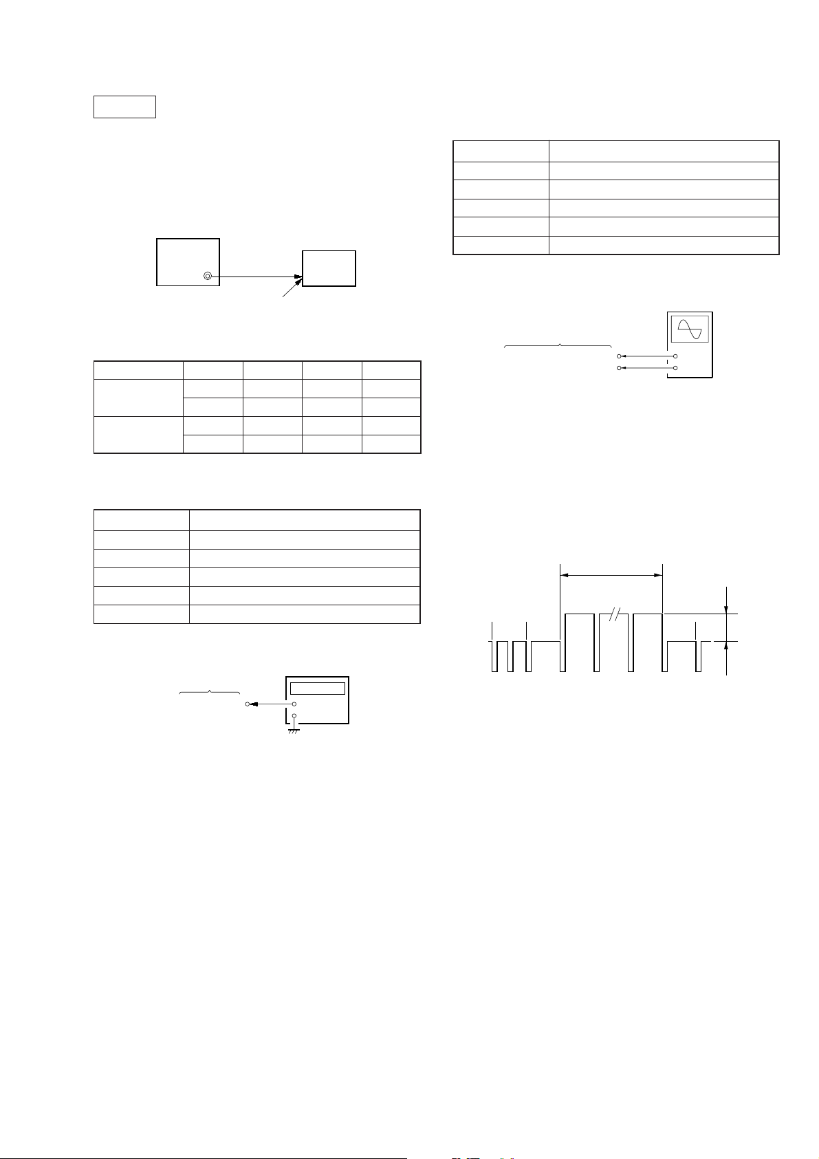
【準備】
下図のように,電気構成ブロックを接続する。
パターン
ジェネレータ
S-VIDEOジャック
JK-136(F)基板
(J1401)
RGB端子
MA-324(F)基板
(J101)
5. 入力信号のセットアップ
(1) ビデオ確認
本機の調整にはパターンジェネレータから得られるビデ
オ信号を調整信号として用いますので,このビデオ出力
信号が規格内に入っていることが必要です。
映像入力端子にオシロスコープを接続し,ビデオ信号の
同期信号振幅が約0.3V,映像部分の振幅が約0.7V,バー
スト信号の振幅が約0.3Vで平坦になっていること,バー
スト信号と「赤」信号のレベル比が0.30:0.66であること
を確認して下さい。
• カラーバー信号入力時
図3-1. パターンジェネレータのカラーバー信号
(2) PC信号(RGB信号)
Signalmode
H V HDISP VDISP
(kHz) (Hz) (ドット)(ドット)
PC98 24.82 56.41 640 400
VGA-TEXT 31.47 70.08 640 362
VGA-GRAP 31.47 59.94 640 480
VGA72 37.86 72.82 640 480
VGA75 37.50 74.99 640 480
MAC13 35.00 66.67 640 480
VGA85 43.27 85.01 640 480
SVGA56 35.16 56.26 800 600
SVGA60 37.88 60.32 800 600
SVGA72 48.08 72.19 800 600
SVGA75 46.88 75.01 800 600
SVGA85 53.68 85.07 800 600
MAC16 49.73 74.55 832 624
XGA60 48.36 59.99 1024 768
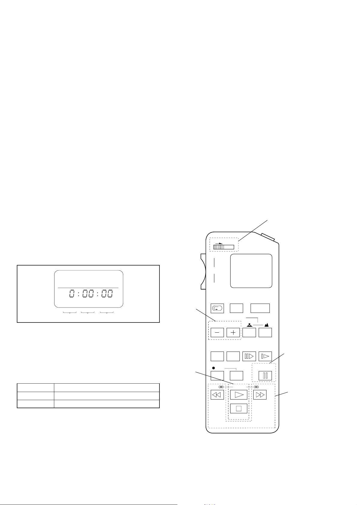
調整リモコン
(J-6082-053-B)
DC8.4V
DCIN8.4Vジャック
DD-107(F)基板
(J701)
RM-95
延長ケーブル
(J-6082-291-A)
セット PC
MA-324(F)基板
CN501
3-1
【調整前の準備】
1. サービス治具
1. 調整リモコン(RM-95-部改造品) 注1:J-6082-053-B
2. 延長ケーブル(リモコンプラグ変換用) J-6082-291-A
注1:調整リモコン内のマイコンICが新マイコン(uPD7503-
G-C56-12)でないとページ切換が出来ません。この場
合には新マイコン(8-759-148-35)に交換してください。
2. 調整リモコン
調整を行うためには,不揮発性メモリ(EEPROM)に書き
込まれている調整データを書き換える必要があり,この
ために,調整リモコンが使用されます。
調整リモコンは,リモコン信号線(LANC)を使ってセッ
トと双方向通信を行います。調整リモコンからセットへ
は,ページ,アドレスおよびデータのアップ/ダウンコ
マンドが送信されます。セットから調整リモコンへは,
ページ,アドレスおよびデータが送信されます。
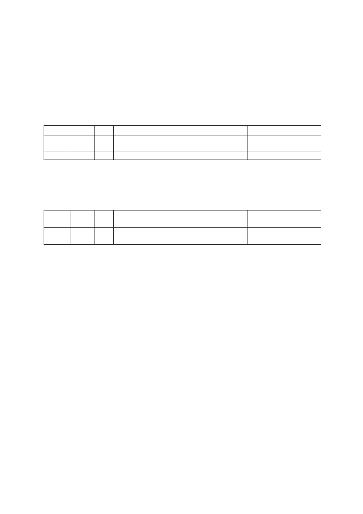
3. 調整リモコンの使用方法
1. MA-324(F)基板のCN501に延長ケーブル(J-6082-291-A)
を介して調整リモコンを接続する。
この時,延長ケーブルのスイッチはOFF(OPEN)に
(
しておく
セットの電源をONにし,[PC]または[VIDEO]モードに
する。
2. 調整リモコンのHOLDスイッチをHOLD(サービスモー
ド)位置にする。
接続が正常ならば,調整リモコンのLCDに図3-2.のよ
うな表示がされます。
• 調整データの書き込み
調整データ(E またはF ページ)を不揮発性メモリ
(EEPROM)に書き込むためにはPAUSEボタンを押す
必要があります。(この操作を行わない場合,新しい
データは不揮発性メモリに記憶されません)
4. ページ:0,アドレス:01を選択し,データを01にしま
す。これによってEまたはFページのデータ入力が可能
になります。
5. 調整終了後はページ:0,アドレス:01を選択し,デー
タを00にします。これによって, EまたはF ページの
データ変更を禁止することが出来ます。
6. 全調整終 了後はメイン電源(8.4V)を一度OFFしてくだ
さい。
4. 調整リモコン使用上の注意(重要)
調整リモコンの操作ミスによって,正しいデータを消去
してしまう場合があります。これを防止するため調整を
行う前にEおよびFページのデータをメモしておくこと,
および一項目の調整が終了するたびに新しい調整データ
をメモすることをお勧めします。
調整リモコンRM-95(J-6082-053-B)
)
HOLD
WIDE
通常モード(NOR)/
サービスモード(ADJ)の切換
START/
STOP
ページ データアドレス
図 3-2.
3. 調整リモコンは次のように操作します。
• ページの変更
EDITSEARCH+ボタンを押すとページは増加します。
EDITSEARCH−ボタンを押すとページは減少します。
ページは0からFまでの16ページがあります。
16進数 0123456789ABCDE F
LCD上の表示 0123456789AbcdEF
10進数換算値 0 1 2 3 456789101112131415
• アドレスの変更
FF(M)ボタンを押すと,アドレスは増加します。
REW(m)ボタンを押すと,アドレスは減少します。
アドレスは00からFFの256のアドレスがあります。
• データの変更(データのセット)
PLAY(N)ボタンを押すと,データは増加します。
STOP(x)ボタンを押すと,データは減少します。
データは00からFFの256の値があります。
ページ変更
データ変更
ZOOM
TELE
REC
REVIEW
COUNTER
RESET DISPLAY FRAME SLOW
REW
FOCUS
AUTO/MAN
EDIT SEARCH
REC
STOP
PB
POWER
PAUSE
FF
RM-95
図 3-3.
データ書き込み
アドレス変更
3-2

5. データ処理
一部の調整項目において,調整データを得るためにマイコンデータを読み取り,治具や調整リモコンの表示データ(16進
数)の演算を必要とします。この場合,16進数を一旦10進数に変換した後に演算を行い,その解を16進数に変換して調整
データとして下さい。表1.に16進数−10進数変換表を示します。
16進数−10進数変換表
16進数
の下位桁
16進数の
上位桁
0 0 1 2 3 4 5 6 7 8 9 10 11 12 13 14 15
1 16171819202122232425262728293031
2 32333435363738394041424344454647
3 48495051525354555657585960616263
4 64656667686970717273747576777879
5 80818283848586878889909192939495
6 96 97 98 99 100 101 102 103 104 105 106 107 108 109 110 111
7 112 113 114 115 116 117 118 119 120 121 122 123 124 125 126 127
8 128 129 130 131 132 133 134 135 136 137 138 139 140 141 142 143
9 144 145 146 147 148 149 150 151 152 153 154 155 156 157 158 159
A(A) 160 161 162 163 164 165 166 167 168 169 170 171 172 173 174 175
B(b) 176 177 178 179 180 181 182 183 184 185 186 187 188 189 190 191
1→
C(c) 192 193 194 195 196 197 198 199 200 201 202 203 204 205 206 207
D(d) 208 209 210 211 212 213 214 215 216 217 218 219 220 221 222 223
E(E) 224 225 226 227 228 229 230 231 232 233 234 235 236 237 238 239
F(F) 240 241 242 243 244 245 246 247 248 249 250 251 252 253 254 255
0123456789
ABCDEF
(A)(b)(c)(d)(E)(F)
2
↓
表1.
注:( )内は治具または調整リモコンの表示
(例)治具または調整リモコンの表示がBD(bd)の場合。
16進数の上位桁がB(b),下位がD(d)であることから上表の1と2の交点,189が求める10進数になります。
3-3
6. 調整時の電源投入手順
1. 延長ケーブル,調整リモコンをつなぐ。
2. 調整リモコンのHOLDスイッチが入っていないこと(左(NOR)位置)を確認し,DCIN8.4Vジャック(J701)に8.4Vdcを投
入する。
(HOLDスイッチがHOLDになっているとセットの初期動作が終了できず,電源スイッチが機能しません)
3. セットの電源スイッチを入れる。この時緑LED点灯を確認する。
4. セットを[PC]または[VIDEO]モードにする。
5. 調整リモコンのHOLDスイッチをHOLD(右(ADJ)位置)にする。
7. 調整終了手順
順序 ページ アドレス データ 作業内容 備考
(1) EまたはF
(2) 0 01 00 左記のページ,アドレスにデータの値をセットする。書き込みプロテクト
(3) 調整リモコンのHOLDスイッチのHOLDを解除(NOR位置)する。
8. パスワード・リセット(セットの動作確認をするとき)
1. 電源スイッチを入れてから電源BOX底面の「パスワード リセット」を押してお客様の設定したパスワードをリセットする。
2. PUSHDISPLAYダイヤルを操作して「パスワード設定画面」で『いいえ』を設定しパスワード不使用設定にする。
又は
順序 ページ アドレス データ 作業内容 備考
(1) 0 01 01 左記のページ,アドレスにデータの値をセットする。プロテクト解除
(2)
(3) :全ての調整,動作確認を行った最後に電源スイッチを入れ,電源BOX底面の「パスワードリセット」を押
F8A01
し,電源スイッチを切る。
左記のページ,アドレスに調整した値が正しく
書き込まれているか確認する。
左記のページ,アドレスにデータの値をセットし,
PAUSEを押す。
パスワード不使用設定
9. 画質音質標準設定:
1. セットを
2. MENUボタンを押してメニューを表示させる。
3. PUSHDISPLAYダイヤルを操作して画質および音質を以下のように設定する。
(1)RESETを選択および決定する。
(2)AVLS:OFF
(3)MEGABASS:0
(4)POWERSAVE:OFF
4. セットを
5. MENUボタンを押してメニューを表示させる。
6. RESETを選択および決定する。
7. 各ダイヤルおよびスイッチを以下のように設定する。
(1)BRIGHTダイヤル:センタ
(2)VOLダイヤル:3から6の間
(3)SCREENスイッチ:ON
(4)SETTHROUGH:CLOSE端
[PC]モードにする。
[VIDEO]モードにする。
3-4
【プリセットデータ書き込み】
接続:
(1) MA-324(F)基板CN501に調整リモコンを接続し,
データ書き込み方法
(1) ページ:0,アドレス:01にデータ:01をセットする。
(2) 下表のデータを入力する。
注:データをEEPROMに書き込むため,データをセットするたびに調整リモコンのPAUSEボタンを押してください。
(3) 全データ書き込みの後,ページ:0,アドレス:01にデータ:00をセットする。
E,Fページ調整アドレスと初期設定データ
IC502(EEPROM)を交換したときのみ設定し所定の調整を行ってください。
E:ページ
アドレス データ 備考
00 01 固定値
01 EB
02 DC
03 DA
04 8C
05 DE
06 4C
07 1D
08 08
09 07
0A 30 固定値
0B 75
0C 90
0D 7E
0E 40
0F-FF − 不使用
F:ページ
アドレス データ 備考
00-0F − 不使用
10 40
11 01
12 0F
13 FF
14 01
15 07
16 FF
17 00
18 00
19 FF 固定値
1A FF
1B FF
1C FF
1D FF
1E FF
1F FF
20 00
21 03
22 DE
23 86
24 12
充電動作
調整
アドレス データ 備考
[VIDEO]モード(S904)にする。
25 1F
26 00
27 00
28 01
29 03
2A 02
2B 05
2C 1D
2D FC
2E 1F
2F 18
30 04
31 40
32 10
33 06
34 47
35 03
36 00
37 00
38 00 固定値
39 24
3A 24
3B 24
3C 4C
3D 4C
3E 4C
3F 3F
40 3F
41 3F
42 9C
43 9C
44 9C
45 00
46 00
47 00
48 40
49 40
4A 40
4B C1
4C C0
4D C0
アドレス データ 備考
4E 41
4F 00
50 40
51 3F
52 7A ミュート調整
53 3F
54 5B
55 80 4fsc調整
56 87 H-Sync調整
57 80 装着センサ調整
58 00
59 00
5A 00
5B 00
5C 80
5D 80
5E 80
5F AE 固定値
60 AE
61 AE
62 03
63 03
64 03
65 2F
66 2F
67 2F
68 65 RGain調整
69 65 GGain調整
6A 65 BGain調整
6B 94 RBias調整
6C 94 GBias調整
6D 94 BBias調整
6E 80
6F 80
70 80
71 80
72 80
73 80
74 9A センタ調整
75 35 VCOMR調整
76 35 VCOML調整
固定値
固定値
固定値
3-5
アドレス データ 備考
77 00 固定値
78 3E SID調整
79 6A PRG調整
7A 60 BLACK調整
7B IF
7C 00 固定値
7D FF
7E 5B
7F 63
80 73
81 7B
82 80
83 01
84 49
85 FF
86 00
87 00
88 00
89 00
8A 00
8B 00
8C 02 固定値
8D 00
8E 00
8F 00
90 80
91 41
92 00
93 00
94 80
95 41
96 5D CONTRAST調整
97 29 固定値
98 4F カラー調整
99 FF
9A 80
9B FF
9C 01
9D FF
9E FF
9F FF
A0 81
A1 38
A2 20 固定値
A3 3A
A4 1C
A5 40
A6 45
A7 42
A8 45
A9 42
AA A5
AB 44
バッテリ
ダウン
調整
アドレス データ 備考
AC A5
AD 44
AE C0
AF 46
B0 A1
B1 4F
B2 D8
B3 52
B4 11
B5 55
B6 26
B7 58
B8 22
B9 48
BA 5B
BB 4A
BC 17
BD 21
BE A8
BF 22
C0 CB
C1 1A
C2 CF
C3 1B
C4 0C
C5 26 固定値
C6 22
C7 28
C8 99
C9 1E
CA EE
CB 1F
CC E1
CD 1C
CE 10
CF 1E
D0 B2
D1 25
D2 BE
D3 27
D4 D9
D5 1D
D6 1E
D7 1F
D8 1D
D9 2D
DA 14
DB 30
DC 68
DD 1A
DE 68
DF 1A
E0 B4
アドレス データ 備考
E1 28
E2 19
E3 2B
E4 1D
E5 2D
E6 14
E7 30
E8 AD
E9 25
EA B8
EB 27
EC AD
ED 1D
EE EE
EF 1E 固定値
F0 84
F1 28
F2 E3
F3 2A
F4 B6
F5 38
F6 78
F7 3D
F8 CC
F9 1A
FA 03
FB 00
FC 00
FD 00
FE 00 充電動作調整
FF FF 固定値
3-6
ビデオ部
パターンジェネレータ
タ
オシロスコープ
• ビデオ部の調整は下記のようにパターンジェネレータを接
続して下さい。文中に調整用映像入力信号として指示がな
い限りビデオ出力信号(カラーバー信号)を入力して下さ
い。
セット
【ビデオミュートレベル調整】
条件:
入力信号 全黒(IRE0%)信号
測定点 YC-148(F)基板のCN10037ピン
測定器 オシロスコープ
調整ページ F
調整アドレス 52
規格値 0±0.03Vp-p
接続:
S-VIDEOジャック(J1401)
準備:
ページ アドレス データ
サブカラー
信号切替え
PAL F 54 5B
(NTSC) (F) (54) (80)
PAL F 14 01
(NTSC) (F) (14) (00)
【4fscフリーラン調整】
条件:
入力信号 無信号
測定点 YC-148(F)基板のCN10034ピン
測定器 周波数カウンタ
調整ページ F
調整アドレス 55
規格値 17.73450MHz±20Hz(PAL)
接続:
YC-148(F)基板
CN10034ピン
(4FSC)
周波数カウン
+
−
(DCレンジ)
YC-148(F)基板
CN10037ピン(YOUT)
CN10031ピン(GND)
+
−
調整方法:
(1) YC-148(F)基板のCN10037ピンにオシロスコープを接
続する。
(2) ページ:0,アドレス:01にデータ:01をセット(確認)
する。(Fページ:プロテクト解除)
(3) ページ:F,アドレス:52にしてオシロスコープ上の波
形のAレベルが規格値になるよう,PLAY,STOPボタ
ンでデータを変え,PAUSEボタンを押して書き込む。
24H11H
9H 10H 25H
A
調整および接続箇所:YC-148(F)基板(3-30ページ参照)
調整方法:
(1) YC-148(F)基板のCN10034ピンに周波数カウンタを接
(2) ページ:0,アドレス:01にデータ:01をセット(確認)
(3) ページ:F,アドレス:55にし,周波数カウンタの読み
調整および接続箇所:YC-148(F)基板(3-30ページ参照)
続する。
する。
(Fページ:プロテクト解除)
が規格値になるよう,PLAY,STOPでデータを変え,
PAUSEボタンを押して書き込む。
3-7
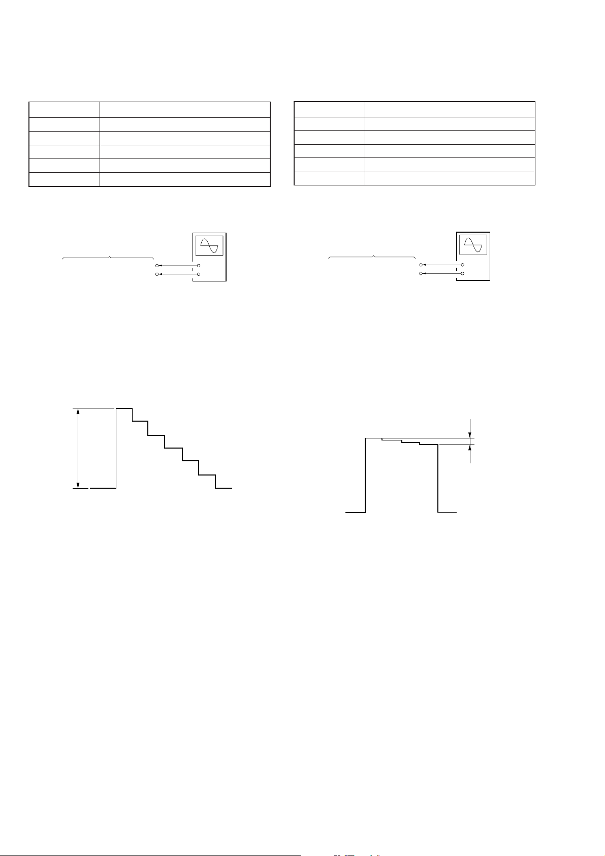
【ビデオCONTRAST調整】
オシロスコープ
オシロスコープ
条件:
入力信号 10ステップ信号(白:100IREレベル)
測定点 YC-148(F)基板のCN10038ピン
測定器 オシロスコープ
調整ページ F
調整アドレス 96
規格値 0.7±0.02Vp-p
【カラー調整】
条件:
入力信号 カラーバー信号
測定点 YC-148(F)基板のCN1003 8ピン
測定器 オシロスコープ
調整ページ F
調整アドレス 98
規格値 0±0.02Vp-p
接続:
(DCレンジ)
YC-148(F)基板
CN10038ピン(VIDEOG)
CN10031ピン(GND)
+
−
調整方法:
(1) YC-148(F)基板のCN10038ピンにオシロスコープを接
続する。
(2) ページ:0,アドレス:01にデータ:01をセット(確認)
する。(Fページ:プロテクト解除)
(3) ページ:F,アドレス:96にしてオシロスコープ上の波
形のBレベルが規格値になるよう,PLAY,STOPボタ
ンでデータを変え,PAUSEボタンを押して書き込む。
B
接続:
(DCレンジ)
YC-148(F)基板
CN10038ピン(VIDEOG)
CN10031ピン(GND)
+
−
調整方法:
(1) YC-148(F)基板のCN10038ピンにオシロスコープを接
続する。
(2) ページ:0,アドレス:01にデータ:01をセット(確認)
する。(Fページ:プロテクト解除)
(3) ページ:F,アドレス:98にしオシロスコープ上の波形
のCレベルが規格値になるよう,PLAY,STOPボタン
でデータを変え,PAUSEボタンを押して書き込む。
C
調整および接続箇所:YC-148(F)基板(3-30ページ参照)
調整および接続箇所:YC-148(F)基板(3-30ページ参照)
3-8
PC部
オシロスコープ
• PC部の調整を行う時は,セットを[PC]モードにして下さ
い。
• MA-324(F)基板のJ101より,PCRGB信号を入力します。
下表にJ101の端子番号と信号名称を記します。
端子番号 信号名称
1 RED
2 GREEN
3 BLUE
4−
5 GND
6 RGBGND
7 RGBGND
8 RGBGND
端子番号 信号名称
9 SYNCGND
10 GND
11 GND
12 −
13 H-SYNC
14 V-SYNC
15 −
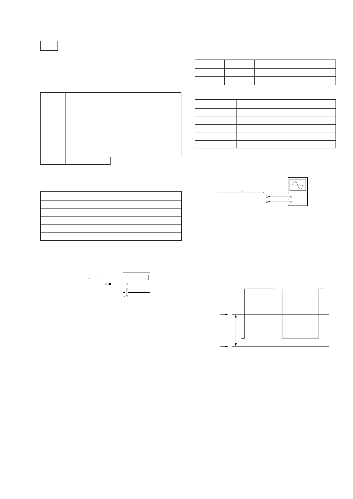
【シグナルセンタレベル調整】
準備:
ページ アドレス データ 備考
F 7B 1F BRIGHT(センタ)
F 11 03 BRIGHT(固定)
条件:
入力信号 SVGA60Hz:全黒信号
測定点 MA-324(F)基 板のCN2063ピン
測定器 オシロスコープ
調整ページ F
調整アドレス 74
規格値 7.0±0.1V
接続:
【H-Sync周波数調整】
条件:
入力信号 無信号
測定点 MA-324(F)基 板のCN2067ピン
測定器 周波数カウンタ
調整ページ F
調整アドレス 56
規格値 38±1kHz
接続:
周波数カウンタ
MA-324(F)基板
CN2067ピン
(INTH)
調整方法:
(1) MA-324(F)基板のCN2067ピンに周波数カウンタを接
続する。
(2) ページ:0,アドレス:01にデータ:01をセット(確認)
する。
(Fページ:プロテクト解除)
(3) ページ:F,アドレス:56にし,周波数カウンタの読み
が規格値になるよう,PLAY,STOPでデータを変え,
PAUSEボタンを押して書き込む。
+
−
(DCレンジ)
MA-324(F)基板
CN2063ピン(SIGG1)
CN2069ピン(GND)
+
−
調整方法:
(1) MA-324(F)基板のCN2063ピンにオシロスコープを接
続する。
(2) ページ:0,アドレス:01にデータ:01をセット(確認)
する。(Fページ:プロテクト解除)
(3) ページ:F,アドレス:74にしオシロスコープ上の波形
のEレベルが規格値になるよう,PLAY,STOPボタン
でデータを変え,PAUSEボタンを押して書き込む。
シグナル
センタ
E
GND
調整および接続箇所:MA-324(F)基板(3-30ページ参照)
調整および接続箇所:MA-324(F)基板(3-30ページ参照)
3-9
 Loading...